EP3908038A1 - Data distribution transmission method, network master node mn and network secondary node sn - Google Patents
Data distribution transmission method, network master node mn and network secondary node sn Download PDFInfo
- Publication number
- EP3908038A1 EP3908038A1 EP20736040.5A EP20736040A EP3908038A1 EP 3908038 A1 EP3908038 A1 EP 3908038A1 EP 20736040 A EP20736040 A EP 20736040A EP 3908038 A1 EP3908038 A1 EP 3908038A1
- Authority
- EP
- European Patent Office
- Prior art keywords
- information
- target
- drb
- resource
- qos flow
- Prior art date
- Legal status (The legal status is an assumption and is not a legal conclusion. Google has not performed a legal analysis and makes no representation as to the accuracy of the status listed.)
- Pending
Links
Images



Classifications
-
- H—ELECTRICITY
- H04—ELECTRIC COMMUNICATION TECHNIQUE
- H04W—WIRELESS COMMUNICATION NETWORKS
- H04W36/00—Hand-off or reselection arrangements
- H04W36/0005—Control or signalling for completing the hand-off
- H04W36/0011—Control or signalling for completing the hand-off for data sessions of end-to-end connection
- H04W36/0033—Control or signalling for completing the hand-off for data sessions of end-to-end connection with transfer of context information
- H04W36/0044—Control or signalling for completing the hand-off for data sessions of end-to-end connection with transfer of context information of quality context information
-
- H—ELECTRICITY
- H04—ELECTRIC COMMUNICATION TECHNIQUE
- H04W—WIRELESS COMMUNICATION NETWORKS
- H04W28/00—Network traffic management; Network resource management
- H04W28/02—Traffic management, e.g. flow control or congestion control
- H04W28/0252—Traffic management, e.g. flow control or congestion control per individual bearer or channel
-
- H—ELECTRICITY
- H04—ELECTRIC COMMUNICATION TECHNIQUE
- H04W—WIRELESS COMMUNICATION NETWORKS
- H04W28/00—Network traffic management; Network resource management
- H04W28/02—Traffic management, e.g. flow control or congestion control
- H04W28/0268—Traffic management, e.g. flow control or congestion control using specific QoS parameters for wireless networks, e.g. QoS class identifier [QCI] or guaranteed bit rate [GBR]
-
- H—ELECTRICITY
- H04—ELECTRIC COMMUNICATION TECHNIQUE
- H04W—WIRELESS COMMUNICATION NETWORKS
- H04W28/00—Network traffic management; Network resource management
- H04W28/02—Traffic management, e.g. flow control or congestion control
- H04W28/08—Load balancing or load distribution
-
- H—ELECTRICITY
- H04—ELECTRIC COMMUNICATION TECHNIQUE
- H04W—WIRELESS COMMUNICATION NETWORKS
- H04W28/00—Network traffic management; Network resource management
- H04W28/02—Traffic management, e.g. flow control or congestion control
- H04W28/08—Load balancing or load distribution
- H04W28/086—Load balancing or load distribution among access entities
- H04W28/0861—Load balancing or load distribution among access entities between base stations
- H04W28/0864—Load balancing or load distribution among access entities between base stations of different hierarchy levels, e.g. Master Evolved Node B [MeNB] or Secondary Evolved node B [SeNB]
-
- H—ELECTRICITY
- H04—ELECTRIC COMMUNICATION TECHNIQUE
- H04W—WIRELESS COMMUNICATION NETWORKS
- H04W28/00—Network traffic management; Network resource management
- H04W28/02—Traffic management, e.g. flow control or congestion control
- H04W28/08—Load balancing or load distribution
- H04W28/09—Management thereof
- H04W28/0958—Management thereof based on metrics or performance parameters
- H04W28/0967—Quality of Service [QoS] parameters
-
- H—ELECTRICITY
- H04—ELECTRIC COMMUNICATION TECHNIQUE
- H04W—WIRELESS COMMUNICATION NETWORKS
- H04W76/00—Connection management
- H04W76/10—Connection setup
- H04W76/15—Setup of multiple wireless link connections
-
- H—ELECTRICITY
- H04—ELECTRIC COMMUNICATION TECHNIQUE
- H04W—WIRELESS COMMUNICATION NETWORKS
- H04W28/00—Network traffic management; Network resource management
- H04W28/02—Traffic management, e.g. flow control or congestion control
- H04W28/10—Flow control between communication endpoints
Definitions
- This disclosure relates to the field of communications technologies, and in particular, to a transmission method with data offloading, a network master node MN, and a network secondary node SN.
- user equipment User Equipment
- UE User Equipment
- a network node may offload a flow of data of the UE to another network node.
- a master node Master Node, MN
- SN Secondary Node
- the SN may establish a data radio bearer (Data Radio Bearer, DRB) or use an existing DRB to transmit the offloaded data. If the DRB transmitting the data is an SN-terminated master cell group (Master Cell Group, MCG) bearer, the DRB transmitting the data may still uses resources of the MN
- Embodiments of this disclosure provide a transmission method with data offloading, a network master node MN, and a network secondary node SN, to resolve a problem of the transmission method with data offloading in the related art that excessive resources of the MN are used, resulting in poor effect of transmission with data offloading.
- an embodiment of this disclosure provides a transmission method with data offloading, applied to an MN, where the method includes:
- an embodiment of this disclosure provides a transmission method with data offloading, applied to a network secondary node SN, where the method includes:
- an embodiment of this disclosure provides an MN, including:
- an embodiment of this disclosure provides an SN, including:
- an embodiment of this disclosure provides an MN, including a memory, a processor, and a computer program stored in the memory and capable of running on the processor, where when the computer program is executed by the processor, the steps of the transmission method with data offloading provided in the first aspect of the embodiments of this disclosure are implemented.
- an embodiment of this disclosure provides an SN, including a memory, a processor, and a computer program stored in the memory and capable of running on the processor, where when the computer program is executed by the processor, the steps of the transmission method with data offloading provided in the second aspect of the embodiments of this disclosure are implemented.
- an embodiment of this disclosure provides a computer-readable storage medium, where the computer-readable storage medium stores a computer program, and when the computer program is executed by a processor, the steps of the transmission method with data offloading provided in the first aspect of the embodiments of this disclosure are implemented, or when the computer program is executed by a processor, the steps of the transmission method with data offloading provided in the second aspect of the embodiments of this disclosure are implemented.
- the MN when the MN offloads a flow of data of UE to the SN, the MN transmits resource indication information to the SN, so that the SN can determine or establish a target DRB according to the resource indication information, and perform effective transmission of the offloaded data on the target DRB. Because the SN determines or establishes the target DRB according to the resource indication information from the MN, this can effectively prevent the SN from using excessive radio resources of the MN during transmission of the target QoS flow, making data offloading of the MN more effective.
- a transmission method with data offloading provided in the embodiments of this disclosure may be applied to a wireless communications system.
- the wireless communications system may be a 5G system, or an evolved long term evolution (Evolved Long Term Evolution, eLTE) system, or a later evolved communications system.
- the communications device may be user equipment or a network-side device.
- FIG. 1 is a structural diagram of a transmission system with data offloading according to an embodiment of this disclosure.
- user equipment may communicate with a plurality of network nodes, for example, with an MN and an SN.
- the transmission system with data offloading includes user equipment 11, an MN 12, and an SN 13.
- the user equipment 11 may be a mobile communications device, such as a mobile phone, a tablet computer (Tablet Personal Computer), a laptop computer (Laptop Computer), a personal digital assistant (personal digital assistant, PDA), a mobile internet device (Mobile Internet Device, MID), or a wearable device (Wearable Device). It should be noted that the user equipment 11 is not limited to any specific type in the embodiments of this disclosure.
- the MN 12 and SN 13 may be network nodes in a 5G communications system, network nodes in a 4G communications system, network nodes in a 3G communications system, network nodes in a later evolved communications system, or the like. It should be noted that the network node is not limited to any specific type in this embodiment of this disclosure.
- UE may be connected to a plurality of network nodes simultaneously.
- UE is connected to an MN and an SN simultaneously.
- the UE can have its traffic carried an SN-supported split bearer or an SN-terminated master cell group (Master Cell Group, MCG) bearer, as shown in FIG. 2 .
- MCG Master Cell Group
- the traffic of the UE can be carried on different data flows (QoS flow).
- QoS flow data flows
- the network node may offload a flow of data of the UE to another network node.
- one or more data flows may be mapped to a same DRB.
- a 5G communications system allows one or more data flows to be offloaded from an MN to an SN, or from an SN to an MN
- the MN may offload a QoS flow (for example, QoS_flow_1) of the UE to the SN.
- a QoS flow for example, QoS_flow_1
- the SN may need to create a new DRB (for example, DRB 1) for QoS_flow_1, or may map QoS_flow_1 to an existing DRB (for example, DRB 2).
- DRB 1 uses resources of the MN
- the DRB 2 is an SN-terminated MCG bearer
- the DRB 2 also uses resources of the MN
- the MN is short of radio resources, if the offloaded QoS_flow_1 still needs to use resources of the MN for transmission, excessive resources of the MN are used, resulting in poor effect of transmission with data offloading.
- the embodiments of this disclosure provide a transmission system with data offloading shown in FIG. 1 , and a transmission method with data offloading applied to the transmission system with data offloading.
- the method is as follows:
- An MN transmits offloading request information to an SN, where the offloading request information includes information about a target QoS flow and resource indication information.
- the SN receives the offloading request information transmitted by the MN
- the SN transmits, according to the resource indication information, the target QoS flow by using a target DRB; or, in a case that the SN is unable to transmit the target QoS flow according to the resource indication information, the SN transmits resource information to the MN, where the resource information is resource information available to the SN for establishing the target DRB, and the target DRB is used to transmit the target QoS flow.
- the MN when the MN offloads a flow of data of UE to the SN, the MN transmits resource indication information to the SN, so that the SN can determine or establish a target DRB according to the resource indication information, and perform effective transmission of the offloaded data on the target DRB. Because the SN determines or establishes the target DRB according to the resource indication information from the MN, this can effectively prevent the SN from using excessive radio resources of the MN during transmission of the target QoS flow, making data offloading of the MN more effective.
- FIG. 3 is a flowchart of a transmission method with data offloading according to an embodiment of this disclosure. As shown in FIG. 3 , the transmission method with data offloading is applied to a network master node MN, and the method includes the following steps.
- Step 301 Transmit offloading request information to a network secondary node SN.
- the offloading request information includes information about a target QoS flow and resource indication information, and the resource indication information is used to indicate that the SN transmits the target QoS flow by using a target DRB.
- the target DRB may be an existing DRB, or may be a DRB established by the SN according to the resource indication information.
- the target QoS flow is originally transmitted on the MN.
- the MN needs to offload the target QoS flow to the SN in order to resolve the shortage of radio resources through data offloading.
- the MN transmits the offloading request information to the SN.
- the offloading request information includes information about a Qos flow to be offloaded by the MN (that is, the information about a target QoS flow), so that the SN learns the information about the Qos flow to be offloaded by the MN
- the offloading request information further includes the resource indication information, so that the SN knows on which resources the target QoS flow can be transmitted, or on which resources the target QoS flow cannot be transmitted.
- the MN can properly indicate resource information to the SN based on usage of radio resources of the MN. This can effectively prevent the SN from using excessive radio resources of the MN during transmission of the target QoS flow, making data offloading of the MN more effective.
- the MN when the MN offloads a flow of data of UE to the SN, the MN transmits resource indication information to the SN, so that the SN can determine or establish a target DRB according to the resource indication information, and perform effective transmission of the offloaded data on the target DRB. Because the SN determines or establishes the target DRB according to the resource indication information from the MN, this can effectively prevent the SN from using excessive radio resources of the MN during transmission of the target QoS flow, making data offloading of the MN more effective.
- the target QoS flow includes at least one of the following:
- one or more QoS flows may be mapped to a same DRB for transmission. Therefore, the MN may need to offload one Qos flow or a plurality of (including two) Qos flows to the SN. In addition, the MN may offload one or more QoS flows on one DRB to the SN, or may offload QoS flows on different DRBs to the SN.
- the MN can flexibly select, based on usage of radio resources of the MN, a Qos flow that needs to be offloaded to the SN, so as to better resolve the shortage of radio resources of the MN. It can be learned that this implementation can improve efficiency and flexibility of transmission with data offloading.
- the resource indication information includes at least one of the following:
- the offloading request information is used to make the SN know on which resources the target QoS flow can be transmitted, or on which resources the target QoS flow cannot be transmitted. Therefore, the resource indication information may include a usable resource set and/or an unusable resource set.
- the MN can indicate at least one set of resources to the SN based on usage of radio resources of the MN. This can effectively prevent the SN from using excessive radio resources of the MN during transmission of the target QoS flow, making data offloading of the MN more effective.
- the SN when the SN receives the offloading request information transmitted by the MN, the SN may have the following two behaviors.
- Manner 1 The SN determines or establishes, according to the resource indication information (a usable resource set and/or an unusable resource set) indicated by the MN, a target DRB to transmit the offloaded target QoS flow. This manner can effectively prevent the SN from using excessive radio resources of the MN during transmission of the target QoS flow, making data offloading of the MN more effective.
- the resource indication information a usable resource set and/or an unusable resource set
- Manner 2 The SN is unable to transmit the target QoS flow according to the resource indication information indicated by the MN.
- the SN can transmit resource information to the MN to advise the MN of other usable resources to transmit the QoS flow, that is, the SN expects the SN to transmit the QoS flow according to the resource information transmitted by the SN.
- the MN receives the resource information transmitted by the SN; and the MN transmits feedback information to the SN.
- the MN may transmit the feedback information to the SN based on usage of radio resources of the MN.
- the feedback information is used to indicate whether the SN can establish a target DRB according to the resource information, or in other words, is used to indicate whether the resource information is usable by the SN to establish a target DRB.
- the SN may feed an advised usable resource set back to the MN Based on the advised usable resource set fed back by the SN, the MN can decide whether to use the usable resource set advised by the SN and feed the decision back to the SN. In this way, through the aforementioned coordination mechanism between the MN and the SN, flexibility of using the radio resources of the MN can be improved.
- the resource indication information includes at least one of the following:
- the target DRB is an SN-terminated DRB.
- FIG. 4 is a flowchart of another transmission method with data offloading according to an embodiment of this disclosure. As shown in FIG. 4 , a transmission method with data offloading is applied to a network secondary node SN, and the method includes the following steps.
- Step 401 Receive offloading request information transmitted by a network master node MN
- the offloading request information includes information about a target QoS flow and resource indication information.
- step 4021 or step 4022 may be performed.
- Step 4021 Transmit, according to the resource indication information, the target QoS flow by using a target DRB.
- the target DRB is used to transmit the target QoS flow.
- Step 4022 Transmit resource information to the MN in a case that the target QoS flow is unable to be transmitted according to the resource indication information.
- the resource information is resource information available to the SN for establishing the target DRB.
- the target DRB is an existing DRB; or the target DRB is a DRB established by the SN according to the resource indication information.
- the method further includes: receiving feedback information transmitted by the MN, where the feedback information is used to indicate whether the resource information is usable by the SN to establish the target DRB, or used to indicate whether the SN can establish the target DRB according to the resource information.
- the target QoS flow includes at least one of the following:
- the resource indication information includes at least one of the following:
- the resource indication information includes at least one of the following:
- the target DRB is an SN-terminated DRB.
- this embodiment of this disclosure is an embodiment of the network secondary node SN corresponding to the embodiment shown in FIG. 3 , and therefore, reference may be made to the relevant descriptions about the embodiment shown in FIG. 3 for specific implementations of this embodiment, which can achieve the same beneficial effect. To avoid repetition, details are not described herein again.
- FIG. 5 is a structural diagram of a network master node MN according to an embodiment of this disclosure. As shown in FIG. 5 , the MN 500 includes:
- the target DRB is an existing DRB; or the target DRB is a DRB established by the SN according to the resource indication information.
- the MN 500 further includes:
- the target QoS flow includes at least one of the following:
- the resource indication information includes at least one of the following:
- the resource indication information includes at least one of the following:
- the target DRB is an SN-terminated DRB.
- the MN 500 in this embodiment of this disclosure may be the MN in any implementation of the method embodiments. Any implementation of the MN in the method embodiments can be implemented by the MN in this embodiment of this disclosure, with the same beneficial effect achieved. To avoid repetition, details are not described herein again.
- FIG. 7 is a structural diagram of a network secondary node SN according to an embodiment of this disclosure. As shown in FIG. 7 , the SN 700 includes:
- the target DRB is an existing DRB; or the target DRB is a DRB established by the SN according to the resource indication information.
- the SN 700 further includes: a second receiving module 703, configured to receive feedback information transmitted by the MN, where the feedback information is used to indicate whether the resource information is usable by the SN to establish the target DRB.
- the target QoS flow includes at least one of the following:
- the resource indication information includes at least one of the following:
- the resource indication information includes at least one of the following:
- the target DRB is an SN-terminated DRB.
- the SN 600 in this embodiment of this disclosure may be the SN in any implementation of the method embodiments. Any implementation of the SN in the method embodiments can be implemented by the SN in this embodiment of this disclosure, with the same beneficial effect achieved. To avoid repetition, details are not described herein again.
- FIG. 9 is a structural diagram of a network master node MN according to an embodiment of this disclosure.
- the MN 900 includes a processor 901, a transceiver 902, a memory 903, and a bus interface.
- the transceiver 902 is configured to:
- the target DRB is an existing DRB; or the target DRB is a DRB established by the SN according to the resource indication information.
- the transceiver 902 is further configured to:
- the target QoS flow includes at least one of the following:
- the resource indication information includes at least one of the following:
- the resource indication information includes at least one of the following:
- the target DRB is an SN-terminated DRB.
- a bus architecture may include any quantity of interconnected buses and bridges, and specifically connect together various circuits of one or more processors represented by the processor 901 and a memory represented by the memory 903.
- the bus architecture may further interconnect various other circuits such as a peripheral device, a voltage regulator, and a power management circuit. These are all common sense in the art, and therefore are not further described in this specification.
- the bus interface provides interfaces.
- the transceiver 902 may be a plurality of components, including a transmitter and a receiver, and provides units for communicating with a variety of other apparatuses on a transmission medium.
- the user interface 904 may also be an interface capable of externally or internally connecting a required device, and the connected device includes but is not limited to a keypad, a display, a speaker, a microphone, a joystick, and the like.
- the processor 901 is responsible for management of the bus architecture and general processing, and the memory 903 may store data for use by the processor 901 when the processor 901 performs an operation.
- the MN 900 in this embodiment may be the MN in any implementation of the method embodiments. Any implementation of the MN in the method embodiments of this disclosure can be implemented by the MN in this embodiment, with the same beneficial effect achieved. Details are not described herein again.
- FIG. 10 is a structural diagram of a network secondary node SN according to an embodiment of this disclosure.
- the SN 1000 includes a processor 1001, a transceiver 1002, a memory 1003, and a bus interface.
- the transceiver 1002 is configured to:
- the target QoS flow includes at least one of the following:
- the resource indication information includes at least one of the following:
- the target DRB is an existing DRB; or the target DRB is a DRB established by the SN according to the resource indication information.
- the transceiver 1002 is further configured to: receive feedback information transmitted by the MN, where the feedback information is used to indicate whether the resource information is usable by the SN to establish the target DRB.
- the resource indication information includes at least one of the following:
- the target DRB is an SN-terminated DRB.
- a bus architecture may include any quantity of interconnected buses and bridges, and specifically connect together various circuits of one or more processors represented by the processor 1001 and a memory represented by the memory 1003.
- the bus architecture may further interconnect various other circuits such as a peripheral device, a voltage regulator, and a power management circuit. These are all common sense in the art, and therefore are not further described in this specification.
- the bus interface provides interfaces.
- the transceiver 1002 may be a plurality of components, including a transmitter and a receiver, and provides units for communicating with a variety of other apparatuses on a transmission medium.
- the user interface 1004 may also be an interface capable of externally or internally connecting a required device, and the connected device includes but is not limited to a keypad, a display, a speaker, a microphone, a joystick, and the like.
- the processor 1001 is responsible for management of the bus architecture and general processing, and the memory 1003 may store data for use by the processor 1001 when the processor 1001 performs an operation.
- the SN 1000 in this embodiment may be the SN in any implementation of the method embodiments of this disclosure. Any implementation of the SN in the method embodiments of this disclosure can be implemented by the SN in this embodiment, with the same beneficial effect achieved. Details are not described herein again.
- An embodiment of this disclosure further provides a computer-readable storage medium, where the computer-readable storage medium stores a computer program.
- the computer program is executed by a processor, the processes of the foregoing transmission method with data offloading embodiment corresponding to the MN or the SN are implemented, with the same technical effect achieved. To avoid repetition, details are not described herein again.
- the computer-readable storage medium is a read-only memory (Read-Only Memory, ROM), a random access memory (Random Access Memory, RAM), a magnetic disk, or an optical disc.
- the method in the foregoing embodiments may be implemented by software on a necessary universal hardware platform or by hardware only. In most cases, the former is a more preferred implementation.
- the technical solutions of this disclosure essentially or a part thereof that contributes to related technologies may be embodied in a form of a software product.
- the computer software product is stored in a storage medium (for example, a ROM/RAM, a magnetic disk, or an optical disc), and includes several instructions for instructing user equipment (which may be a mobile phone, a computer, a server, an air conditioner, a network device, or the like) to perform the methods described in the embodiments of this disclosure.
Landscapes
- Engineering & Computer Science (AREA)
- Computer Networks & Wireless Communication (AREA)
- Signal Processing (AREA)
- Quality & Reliability (AREA)
- Mobile Radio Communication Systems (AREA)
Abstract
Description
- This application claims priority to
Chinese Patent Application No. 201910009585.6 - This disclosure relates to the field of communications technologies, and in particular, to a transmission method with data offloading, a network master node MN, and a network secondary node SN.
- In a multi-connectivity scenario, user equipment (User Equipment, UE) may be connected to a plurality of network nodes simultaneously. When a network node is short of radio resources, the network node may offload a flow of data of the UE to another network node. For example, a master node (Master Node, MN) may offload a flow of data of the UE to a secondary node (Secondary Node, SN).
- The SN may establish a data radio bearer (Data Radio Bearer, DRB) or use an existing DRB to transmit the offloaded data. If the DRB transmitting the data is an SN-terminated master cell group (Master Cell Group, MCG) bearer, the DRB transmitting the data may still uses resources of the MN
- It can be learned that the transmission method with data offloading in the related art has a problem that excessive resources of the MN are used, resulting in poor effect of transmission with data offloading.
- Embodiments of this disclosure provide a transmission method with data offloading, a network master node MN, and a network secondary node SN, to resolve a problem of the transmission method with data offloading in the related art that excessive resources of the MN are used, resulting in poor effect of transmission with data offloading.
- To resolve the foregoing technical problem, this disclosure is implemented as follows:
- According to a first aspect, an embodiment of this disclosure provides a transmission method with data offloading, applied to an MN, where the method includes:
- transmitting offloading request information to a network secondary node SN, where
- the offloading request information includes information about a target data flow (QoS flow) and resource indication information, and the resource indication information is used to indicate that the SN transmits the target QoS flow by using a target DRB.
- According to a second aspect, an embodiment of this disclosure provides a transmission method with data offloading, applied to a network secondary node SN, where the method includes:
- receiving offloading request information transmitted by an MN, where the offloading request information includes information about a target data flow QoS flow and resource indication information; and
- transmitting, according to the resource indication information, the target QoS flow by using a target DRB; or, in a case that the target QoS flow is unable to be transmitted according to the resource indication information, transmitting resource information to the MN, where the resource information is resource information available to the SN for establishing the target DRB.
- According to a third aspect, an embodiment of this disclosure provides an MN, including:
- a first transmitting module, configured to transmit offloading request information to a network secondary node SN, where
- the offloading request information includes information about a target data flow QoS flow and resource indication information, and the resource indication information is used to indicate that the SN transmits the target QoS flow by using a target data radio bearer DRB.
- According to a fourth aspect, an embodiment of this disclosure provides an SN, including:
- a first receiving module, configured to receive offloading request information transmitted by a network master node MN, where the offloading request information includes information about a target data flow QoS flow and resource indication information; and
- a transmission module, configured to: transmit, according to the resource indication information, the target QoS flow by using a target data radio bearer DRB; or, in a case that the target QoS flow is unable to be transmitted according to the resource indication information, transmit resource information to the MN, where the resource information is resource information available to the SN for establishing the target DRB.
- According to a fifth aspect, an embodiment of this disclosure provides an MN, including a memory, a processor, and a computer program stored in the memory and capable of running on the processor, where when the computer program is executed by the processor, the steps of the transmission method with data offloading provided in the first aspect of the embodiments of this disclosure are implemented.
- According to a sixth aspect, an embodiment of this disclosure provides an SN, including a memory, a processor, and a computer program stored in the memory and capable of running on the processor, where when the computer program is executed by the processor, the steps of the transmission method with data offloading provided in the second aspect of the embodiments of this disclosure are implemented.
- According to a seventh aspect, an embodiment of this disclosure provides a computer-readable storage medium, where the computer-readable storage medium stores a computer program, and when the computer program is executed by a processor, the steps of the transmission method with data offloading provided in the first aspect of the embodiments of this disclosure are implemented, or when the computer program is executed by a processor, the steps of the transmission method with data offloading provided in the second aspect of the embodiments of this disclosure are implemented.
- In the embodiments of this disclosure, when the MN offloads a flow of data of UE to the SN, the MN transmits resource indication information to the SN, so that the SN can determine or establish a target DRB according to the resource indication information, and perform effective transmission of the offloaded data on the target DRB. Because the SN determines or establishes the target DRB according to the resource indication information from the MN, this can effectively prevent the SN from using excessive radio resources of the MN during transmission of the target QoS flow, making data offloading of the MN more effective.
- To describe the technical solutions in the embodiments of this disclosure more clearly, the following briefly describes the accompanying drawings required for describing the embodiments of this disclosure. Apparently, the accompanying drawings in the following description show merely some embodiments of this disclosure, and persons of ordinary skill in the art may derive other drawings from these accompanying drawings without creative efforts.
-
FIG. 1 is a schematic diagram of a transmission system with data offloading according to an embodiment of this disclosure; -
FIG. 2 is a schematic diagram of QoS flow mapping according to an embodiment of this disclosure; -
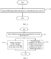
FIG. 3 is a flowchart of a transmission method with data offloading according to an embodiment of this disclosure; -
FIG. 4 is a flowchart of another transmission method with data offloading according to an embodiment of this disclosure; -
FIG. 5 is a structural diagram of a network master node MN according to an embodiment of this disclosure; -
FIG. 6 is a structural diagram of another network master node MN according to an embodiment of this disclosure. -
FIG. 7 is a structural diagram of a network secondary node SN according to an embodiment of this disclosure; -
FIG. 8 is a structural diagram of another network secondary node SN according to an embodiment of this disclosure; -
FIG. 9 is a schematic structural diagram of hardware of a network master node MN according to an embodiment of this disclosure; and -
FIG. 10 is a schematic structural diagram of hardware of a network secondary node SN according to an embodiment of this disclosure. - The following clearly and completely describes the technical solutions in the embodiments of this disclosure with reference to the accompanying drawings in the embodiments of this disclosure. Apparently, the described embodiments are some rather than all of the embodiments of this disclosure. All other embodiments obtained by persons of ordinary skill in the art based on the embodiments of this disclosure without creative efforts shall fall within the protection scope of this disclosure.
- Terms "include", "comprise" and any other variants thereof in the specification and claims of the application are intended to cover the non-exclusive inclusion. For example, a process, method, system, product, or device that includes a series of steps or units is not necessarily limited to those expressly listed steps or units, but may include other steps or units not expressly listed or inherent to such process, method, system, product, or device. Moreover, use of "and/or" in the specification and claims represents at least one of the connected objects. For example, A and/or B means three cases: A alone, B alone, or A and B together.
- In the embodiments of this disclosure, terms such as "an example" or "for example" are used to represent giving an example, an instance, or an illustration. Any embodiment or design solution described as "exemplary" or "for example" in the embodiments of this disclosure should not be construed as being more preferred or advantageous than other embodiments or design solutions. Specifically, the terms such as "an example" or "for example" are used to present related concepts in a specific manner.
- The following describes the embodiments of this disclosure with reference to the accompanying drawings. A transmission method with data offloading provided in the embodiments of this disclosure may be applied to a wireless communications system. The wireless communications system may be a 5G system, or an evolved long term evolution (Evolved Long Term Evolution, eLTE) system, or a later evolved communications system. The communications device may be user equipment or a network-side device.
-
FIG. 1 is a structural diagram of a transmission system with data offloading according to an embodiment of this disclosure. In the transmission system with data offloading, user equipment may communicate with a plurality of network nodes, for example, with an MN and an SN. As shown inFIG. 1 , the transmission system with data offloading includesuser equipment 11, anMN 12, and anSN 13. Theuser equipment 11 may be a mobile communications device, such as a mobile phone, a tablet computer (Tablet Personal Computer), a laptop computer (Laptop Computer), a personal digital assistant (personal digital assistant, PDA), a mobile internet device (Mobile Internet Device, MID), or a wearable device (Wearable Device). It should be noted that theuser equipment 11 is not limited to any specific type in the embodiments of this disclosure. TheMN 12 andSN 13 may be network nodes in a 5G communications system, network nodes in a 4G communications system, network nodes in a 3G communications system, network nodes in a later evolved communications system, or the like. It should be noted that the network node is not limited to any specific type in this embodiment of this disclosure. - Before describing the embodiments of this disclosure in detail, the following briefly describes a dual-connectivity scenario and data offloading in a dual-connectivity scenario.
- In a multi-connectivity scenario, UE may be connected to a plurality of network nodes simultaneously. For example, in a dual-connectivity (Dual Connectivity, DC) scenario, UE is connected to an MN and an SN simultaneously. The UE can have its traffic carried an SN-supported split bearer or an SN-terminated master cell group (Master Cell Group, MCG) bearer, as shown in
FIG. 2 . - The traffic of the UE can be carried on different data flows (QoS flow). In a multi-connectivity scenario, when a network node is short of radio resources, the network node may offload a flow of data of the UE to another network node.
- For example, in a 5G access network, one or more data flows may be mapped to a same DRB. In a dual-connectivity scenario, a 5G communications system allows one or more data flows to be offloaded from an MN to an SN, or from an SN to an MN
- When the MN is short of radio resources, the MN may offload a QoS flow (for example, QoS_flow_1) of the UE to the SN. For transmission of QoS_flow_1, the SN may need to create a new DRB (for example, DRB 1) for QoS_flow_1, or may map QoS_flow_1 to an existing DRB (for example, DRB 2). If the SN establishes the DRB 1 as an SN-terminated MCG bearer, the DRB 1 uses resources of the MN; and if the DRB 2 is an SN-terminated MCG bearer, the DRB 2 also uses resources of the MN
- Because the MN is short of radio resources, if the offloaded QoS_flow_1 still needs to use resources of the MN for transmission, excessive resources of the MN are used, resulting in poor effect of transmission with data offloading.
- To resolve the above-mentioned problem, the embodiments of this disclosure provide a transmission system with data offloading shown in
FIG. 1 , and a transmission method with data offloading applied to the transmission system with data offloading. The method is as follows: - An MN transmits offloading request information to an SN, where the offloading request information includes information about a target QoS flow and resource indication information.
- The SN transmits, according to the resource indication information, the target QoS flow by using a target DRB; or, in a case that the SN is unable to transmit the target QoS flow according to the resource indication information, the SN transmits resource information to the MN, where the resource information is resource information available to the SN for establishing the target DRB, and the target DRB is used to transmit the target QoS flow.
- In the embodiments of this disclosure, when the MN offloads a flow of data of UE to the SN, the MN transmits resource indication information to the SN, so that the SN can determine or establish a target DRB according to the resource indication information, and perform effective transmission of the offloaded data on the target DRB. Because the SN determines or establishes the target DRB according to the resource indication information from the MN, this can effectively prevent the SN from using excessive radio resources of the MN during transmission of the target QoS flow, making data offloading of the MN more effective.
-
FIG. 3 is a flowchart of a transmission method with data offloading according to an embodiment of this disclosure. As shown inFIG. 3 , the transmission method with data offloading is applied to a network master node MN, and the method includes the following steps. - Step 301: Transmit offloading request information to a network secondary node SN.
- The offloading request information includes information about a target QoS flow and resource indication information, and the resource indication information is used to indicate that the SN transmits the target QoS flow by using a target DRB.
- The target DRB may be an existing DRB, or may be a DRB established by the SN according to the resource indication information.
- The target QoS flow is originally transmitted on the MN. For some reasons, for example, shortage of radio resources of the MN, the MN needs to offload the target QoS flow to the SN in order to resolve the shortage of radio resources through data offloading.
- In view of this, the MN transmits the offloading request information to the SN.
- The offloading request information includes information about a Qos flow to be offloaded by the MN (that is, the information about a target QoS flow), so that the SN learns the information about the Qos flow to be offloaded by the MN
- The offloading request information further includes the resource indication information, so that the SN knows on which resources the target QoS flow can be transmitted, or on which resources the target QoS flow cannot be transmitted. The MN can properly indicate resource information to the SN based on usage of radio resources of the MN. This can effectively prevent the SN from using excessive radio resources of the MN during transmission of the target QoS flow, making data offloading of the MN more effective.
- It can be learned that, in this embodiment of this disclosure, when the MN offloads a flow of data of UE to the SN, the MN transmits resource indication information to the SN, so that the SN can determine or establish a target DRB according to the resource indication information, and perform effective transmission of the offloaded data on the target DRB. Because the SN determines or establishes the target DRB according to the resource indication information from the MN, this can effectively prevent the SN from using excessive radio resources of the MN during transmission of the target QoS flow, making data offloading of the MN more effective.
- Optionally, the target QoS flow includes at least one of the following:
- at least one QoS flow on one DRB; and
- at least two QoS flows on at least two DRBs.
- In a 5G access network, one or more QoS flows may be mapped to a same DRB for transmission. Therefore, the MN may need to offload one Qos flow or a plurality of (including two) Qos flows to the SN. In addition, the MN may offload one or more QoS flows on one DRB to the SN, or may offload QoS flows on different DRBs to the SN.
- In this way, the MN can flexibly select, based on usage of radio resources of the MN, a Qos flow that needs to be offloaded to the SN, so as to better resolve the shortage of radio resources of the MN. It can be learned that this implementation can improve efficiency and flexibility of transmission with data offloading.
- Optionally, the resource indication information includes at least one of the following:
- a usable resource set; and
- an unusable resource set.
- As mentioned above, the offloading request information is used to make the SN know on which resources the target QoS flow can be transmitted, or on which resources the target QoS flow cannot be transmitted. Therefore, the resource indication information may include a usable resource set and/or an unusable resource set.
- In this way, the MN can indicate at least one set of resources to the SN based on usage of radio resources of the MN. This can effectively prevent the SN from using excessive radio resources of the MN during transmission of the target QoS flow, making data offloading of the MN more effective.
- In this embodiment of this disclosure, when the SN receives the offloading request information transmitted by the MN, the SN may have the following two behaviors.
- Manner 1: The SN determines or establishes, according to the resource indication information (a usable resource set and/or an unusable resource set) indicated by the MN, a target DRB to transmit the offloaded target QoS flow. This manner can effectively prevent the SN from using excessive radio resources of the MN during transmission of the target QoS flow, making data offloading of the MN more effective.
- Manner 2: The SN is unable to transmit the target QoS flow according to the resource indication information indicated by the MN. In this case, the SN can transmit resource information to the MN to advise the MN of other usable resources to transmit the QoS flow, that is, the SN expects the SN to transmit the QoS flow according to the resource information transmitted by the SN.
- In this manner, the MN receives the resource information transmitted by the SN; and the MN transmits feedback information to the SN.
- When the MN receives the resource information transmitted by the SN, the MN may transmit the feedback information to the SN based on usage of radio resources of the MN. The feedback information is used to indicate whether the SN can establish a target DRB according to the resource information, or in other words, is used to indicate whether the resource information is usable by the SN to establish a target DRB.
- In this manner, if the SN is unable to establish the target DRB according to the resource indication information indicated by the MN to complete transmission of the target QoS flow, the SN may feed an advised usable resource set back to the MN Based on the advised usable resource set fed back by the SN, the MN can decide whether to use the usable resource set advised by the SN and feed the decision back to the SN. In this way, through the aforementioned coordination mechanism between the MN and the SN, flexibility of using the radio resources of the MN can be improved.
- Optionally, the resource indication information includes at least one of the following:
- a bearer type, where the bearer type includes at least one of split (Split) bearer, master cell group MCG bearer, and secondary cell group (Secondary Cell Group, SCG) bearer; and
- a mapping relationship between QoS flows and DRBs.
- Optionally, the target DRB is an SN-terminated DRB.
-
FIG. 4 is a flowchart of another transmission method with data offloading according to an embodiment of this disclosure. As shown inFIG. 4 , a transmission method with data offloading is applied to a network secondary node SN, and the method includes the following steps. - The offloading request information includes information about a target QoS flow and resource indication information.
- After
step 401 is performed,step 4021 or step 4022 may be performed. - Step 4021: Transmit, according to the resource indication information, the target QoS flow by using a target DRB.
- The target DRB is used to transmit the target QoS flow.
- Step 4022: Transmit resource information to the MN in a case that the target QoS flow is unable to be transmitted according to the resource indication information.
- The resource information is resource information available to the SN for establishing the target DRB.
- Optionally, the target DRB is an existing DRB; or
the target DRB is a DRB established by the SN according to the resource indication information. - Optionally, if the SN transmits the resource information to the MN, the method further includes:
receiving feedback information transmitted by the MN, where the feedback information is used to indicate whether the resource information is usable by the SN to establish the target DRB, or used to indicate whether the SN can establish the target DRB according to the resource information. - Optionally, the target QoS flow includes at least one of the following:
- at least one QoS flow on one DRB; and
- at least two QoS flows on at least two DRBs.
- Optionally, the resource indication information includes at least one of the following:
- a usable resource set; and
- an unusable resource set.
- Optionally, the resource indication information includes at least one of the following:
- a bearer type, where the bearer type includes at least one of split bearer, master cell group MCG bearer, and secondary cell group SCG bearer; and
- a mapping relationship between QoS flows and DRBs.
- Optionally, the target DRB is an SN-terminated DRB.
- It should be noted that this embodiment of this disclosure is an embodiment of the network secondary node SN corresponding to the embodiment shown in
FIG. 3 , and therefore, reference may be made to the relevant descriptions about the embodiment shown inFIG. 3 for specific implementations of this embodiment, which can achieve the same beneficial effect. To avoid repetition, details are not described herein again. -
FIG. 5 is a structural diagram of a network master node MN according to an embodiment of this disclosure. As shown inFIG. 5 , theMN 500 includes: - a
first transmitting module 501, configured to transmit offloading request information to a network secondary node SN, where - the offloading request information includes information about a target QoS flow and resource indication information, and the resource indication information is used to indicate that the SN transmits the target QoS flow by using a target data radio bearer DRB.
- Optionally, the target DRB is an existing DRB; or
the target DRB is a DRB established by the SN according to the resource indication information. - Optionally, as shown in
FIG. 6 , theMN 500 further includes: - a
receiving module 502, configured to receive resource information transmitted by the SN; and - a
second transmitting module 503, configured to transmit feedback information to the SN; where - the resource information is resource information available to the SN for establishing the target DRB, and the feedback information is used to indicate whether the resource information is usable by the SN to establish the target DRB.
- Optionally, the target QoS flow includes at least one of the following:
- at least one QoS flow on one DRB; and
- at least two QoS flows on at least two DRBs.
- Optionally, the resource indication information includes at least one of the following:
- a usable resource set; and
- an unusable resource set.
- Optionally, the resource indication information includes at least one of the following:
- a bearer type, where the bearer type includes at least one of split bearer, master cell group MCG bearer, and secondary cell group SCG bearer; and
- a mapping relationship between QoS flows and DRBs.
- Optionally, the target DRB is an SN-terminated DRB.
- It should be noted that the
MN 500 in this embodiment of this disclosure may be the MN in any implementation of the method embodiments. Any implementation of the MN in the method embodiments can be implemented by the MN in this embodiment of this disclosure, with the same beneficial effect achieved. To avoid repetition, details are not described herein again. -
FIG. 7 is a structural diagram of a network secondary node SN according to an embodiment of this disclosure. As shown inFIG. 7 , theSN 700 includes: - a
first receiving module 701, configured to receive offloading request information transmitted by a network master node MN, where the offloading request information includes information about a target QoS flow and resource indication information; and - a
transmission module 702, configured to: transmit, according to the resource indication information, the target QoS flow by using a target data radio bearer DRB; or, in a case that the target QoS flow is unable to be transmitted according to the resource indication information, transmit resource information to the MN, where the resource information is resource information available to the SN for establishing the target DRB. - Optionally, the target DRB is an existing DRB; or
the target DRB is a DRB established by the SN according to the resource indication information. - Optionally, if the SN transmits the resource information to the MN, as shown in
FIG. 8 , theSN 700 further includes:
asecond receiving module 703, configured to receive feedback information transmitted by the MN, where the feedback information is used to indicate whether the resource information is usable by the SN to establish the target DRB. - Optionally, the target QoS flow includes at least one of the following:
- at least one QoS flow on one DRB; and
- at least two QoS flows on at least two DRBs.
- Optionally, the resource indication information includes at least one of the following:
- a usable resource set; and
- an unusable resource set.
- Optionally, the resource indication information includes at least one of the following:
- a bearer type, where the bearer type includes at least one of split bearer, master cell group MCG bearer, and secondary cell group SCG bearer; and
- a mapping relationship between QoS flows and DRBs.
- Optionally, the target DRB is an SN-terminated DRB.
- It should be noted that the SN 600 in this embodiment of this disclosure may be the SN in any implementation of the method embodiments. Any implementation of the SN in the method embodiments can be implemented by the SN in this embodiment of this disclosure, with the same beneficial effect achieved. To avoid repetition, details are not described herein again.
-
FIG. 9 is a structural diagram of a network master node MN according to an embodiment of this disclosure. As shown inFIG. 9 , theMN 900 includes aprocessor 901, atransceiver 902, amemory 903, and a bus interface. - The
transceiver 902 is configured to: - transmit offloading request information to a network secondary node SN, where
- the offloading request information includes information about a target QoS flow and resource indication information, and the resource indication information is used to indicate that the SN transmits the target QoS flow by using a target data radio bearer DRB.
- Optionally, the target DRB is an existing DRB; or
the target DRB is a DRB established by the SN according to the resource indication information. - Optionally, the
transceiver 902 is further configured to: - receive resource information transmitted by the SN; and
- transmit feedback information to the SN; where
- the resource information is resource information available to the SN for establishing the target DRB, and the feedback information is used to indicate whether the resource information is usable by the SN to establish the target DRB.
- Optionally, the target QoS flow includes at least one of the following:
- at least one QoS flow on one DRB; and
- at least two QoS flows on at least two DRBs.
- Optionally, the resource indication information includes at least one of the following:
- a usable resource set; and
- an unusable resource set.
- Optionally, the resource indication information includes at least one of the following:
- a bearer type, where the bearer type includes at least one of split bearer, master cell group MCG bearer, and secondary cell group SCG bearer; and
- a mapping relationship between QoS flows and DRBs.
- Optionally, the target DRB is an SN-terminated DRB.
- In
FIG. 9 , a bus architecture may include any quantity of interconnected buses and bridges, and specifically connect together various circuits of one or more processors represented by theprocessor 901 and a memory represented by thememory 903. The bus architecture may further interconnect various other circuits such as a peripheral device, a voltage regulator, and a power management circuit. These are all common sense in the art, and therefore are not further described in this specification. The bus interface provides interfaces. Thetransceiver 902 may be a plurality of components, including a transmitter and a receiver, and provides units for communicating with a variety of other apparatuses on a transmission medium. For different user equipment, the user interface 904 may also be an interface capable of externally or internally connecting a required device, and the connected device includes but is not limited to a keypad, a display, a speaker, a microphone, a joystick, and the like. - The
processor 901 is responsible for management of the bus architecture and general processing, and thememory 903 may store data for use by theprocessor 901 when theprocessor 901 performs an operation. - It should be noted that the
MN 900 in this embodiment may be the MN in any implementation of the method embodiments. Any implementation of the MN in the method embodiments of this disclosure can be implemented by the MN in this embodiment, with the same beneficial effect achieved. Details are not described herein again. -
FIG. 10 is a structural diagram of a network secondary node SN according to an embodiment of this disclosure. As shown inFIG. 10 , theSN 1000 includes aprocessor 1001, atransceiver 1002, amemory 1003, and a bus interface. - The
transceiver 1002 is configured to: - receive offloading request information transmitted by a network master node MN, where the offloading request information includes information about a target QoS flow and resource indication information; and
- transmit, according to the resource indication information, the target QoS flow by using a target data radio bearer DRB; or, in a case that the target QoS flow is unable to be transmitted according to the resource indication information, transmit resource information to the MN, where the resource information is resource information available to the SN for establishing the target DRB.
- Optionally, the target QoS flow includes at least one of the following:
- at least one QoS flow on one DRB; and
- at least two QoS flows on at least two DRBs.
- Optionally, the resource indication information includes at least one of the following:
- a usable resource set; and
- an unusable resource set.
- Optionally, the target DRB is an existing DRB; or
the target DRB is a DRB established by the SN according to the resource indication information. - Optionally, if the SN transmits the resource information to the MN, the
transceiver 1002 is further configured to:
receive feedback information transmitted by the MN, where the feedback information is used to indicate whether the resource information is usable by the SN to establish the target DRB. - Optionally, the resource indication information includes at least one of the following:
- a bearer type, where the bearer type includes at least one of split bearer, master cell group MCG bearer, and secondary cell group SCG bearer; and
- a mapping relationship between QoS flows and DRBs.
- Optionally, the target DRB is an SN-terminated DRB.
- In
FIG. 10 , a bus architecture may include any quantity of interconnected buses and bridges, and specifically connect together various circuits of one or more processors represented by theprocessor 1001 and a memory represented by thememory 1003. The bus architecture may further interconnect various other circuits such as a peripheral device, a voltage regulator, and a power management circuit. These are all common sense in the art, and therefore are not further described in this specification. The bus interface provides interfaces. Thetransceiver 1002 may be a plurality of components, including a transmitter and a receiver, and provides units for communicating with a variety of other apparatuses on a transmission medium. For different user equipment, the user interface 1004 may also be an interface capable of externally or internally connecting a required device, and the connected device includes but is not limited to a keypad, a display, a speaker, a microphone, a joystick, and the like. - The
processor 1001 is responsible for management of the bus architecture and general processing, and thememory 1003 may store data for use by theprocessor 1001 when theprocessor 1001 performs an operation. - It should be noted that the
SN 1000 in this embodiment may be the SN in any implementation of the method embodiments of this disclosure. Any implementation of the SN in the method embodiments of this disclosure can be implemented by the SN in this embodiment, with the same beneficial effect achieved. Details are not described herein again. - An embodiment of this disclosure further provides a computer-readable storage medium, where the computer-readable storage medium stores a computer program. When the computer program is executed by a processor, the processes of the foregoing transmission method with data offloading embodiment corresponding to the MN or the SN are implemented, with the same technical effect achieved. To avoid repetition, details are not described herein again. For example, the computer-readable storage medium is a read-only memory (Read-Only Memory, ROM), a random access memory (Random Access Memory, RAM), a magnetic disk, or an optical disc.
- It should be noted that the terms "comprise", "include", or any of their variants in this specification are intended to cover a non-exclusive inclusion, so that a process, a method, an article, or an apparatus that includes a list of elements not only includes those elements but also includes other elements that are not expressly listed, or further includes elements inherent to such process, method, article, or apparatus. In absence of more constraints, an element preceded by "includes a..." does not preclude the existence of other identical elements in the process, method, article, or apparatus that includes the element.
- According to the description of the foregoing implementations, persons skilled in the art can clearly understand that the method in the foregoing embodiments may be implemented by software on a necessary universal hardware platform or by hardware only. In most cases, the former is a more preferred implementation. Based on such an understanding, the technical solutions of this disclosure essentially or a part thereof that contributes to related technologies may be embodied in a form of a software product. The computer software product is stored in a storage medium (for example, a ROM/RAM, a magnetic disk, or an optical disc), and includes several instructions for instructing user equipment (which may be a mobile phone, a computer, a server, an air conditioner, a network device, or the like) to perform the methods described in the embodiments of this disclosure.
- The foregoing descriptions are only specific implementations of this disclosure, but are not intended to limit the protection scope of this disclosure. Any variation or replacement readily figured out by persons skilled in the art within the technical scope disclosed in this disclosure shall fall within the protection scope of this disclosure. Therefore, the protection scope of this disclosure shall be subject to the protection scope of the claims.
Claims (17)
- A transmission method with data offloading, applied to a network master node MN, wherein the method comprises:transmitting offloading request information to a network secondary node SN, whereinthe offloading request information comprises information about a target QoS flow and resource indication information, and the resource indication information is used to indicate that the SN transmits the target QoS flow by using a target data radio bearer DRB.
- The method according to claim 1, wherein the target DRB is an existing DRB; or
the target DRB is a DRB established by the SN according to the resource indication information. - The method according to claim 1, further comprising:receiving resource information transmitted by the SN; andtransmitting feedback information to the SN; whereinthe resource information is resource information available to the SN for establishing the target DRB, and the feedback information is used to indicate whether the resource information is usable by the SN to establish the target DRB.
- The method according to claim 1, wherein the resource indication information comprises at least one of the following:a bearer type, wherein the bearer type comprises at least one of split bearer, master cell group MCG bearer, and secondary cell group SCG bearer; anda mapping relationship between QoS flows and DRBs.
- The method according to claim 1, wherein the target DRB is an SN-terminated DRB.
- A transmission method with data offloading, applied to a network secondary node SN, wherein the method comprises:receiving offloading request information transmitted by a network master node MN, wherein the offloading request information comprises information about a target QoS flow and resource indication information; andtransmitting, according to the resource indication information, the target QoS flow by using a target data radio bearer DRB; or, in a case that the target QoS flow is unable to be transmitted according to the resource indication information, transmitting resource information to the MN, wherein the resource information is resource information available to the SN for establishing the target DRB.
- The method according to claim 6, wherein the target DRB is an existing DRB; or
the target DRB is a DRB established by the SN according to the resource indication information. - The method according to claim 6, wherein if the SN transmits the resource information to the MN, the method further comprises:
receiving feedback information transmitted by the MN, wherein the feedback information is used to indicate whether the resource information is usable by the SN to establish the target DRB. - The method according to claim 6, wherein the resource indication information comprises at least one of the following:a bearer type, wherein the bearer type comprises at least one of split bearer, master cell group MCG bearer, and secondary cell group SCG bearer; anda mapping relationship between QoS flows and DRBs.
- The method according to claim 6, wherein the target DRB is an SN-terminated DRB.
- A network master node MN, comprising:a first transmitting module, configured to transmit offloading request information to a network secondary node SN, whereinthe offloading request information comprises information about a target QoS flow and resource indication information, and the resource indication information is used to indicate that the SN transmits the target QoS flow by using a target data radio bearer DRB.
- The MN according to claim 11, further comprising:a receiving module, configured to receive resource information transmitted by the SN; anda second transmitting module, configured to transmit feedback information to the SN; whereinthe resource information is resource information available to the SN for establishing the target DRB, and the feedback information is used to indicate whether the resource information is usable by the SN to establish the target DRB.
- A network secondary node SN, comprising:a first receiving module, configured to receive offloading request information transmitted by a network master node MN, wherein the offloading request information comprises information about a target QoS flow and resource indication information; anda transmission module, configured to: transmit, according to the resource indication information, the target QoS flow by using a target data radio bearer DRB; or, in a case that the target QoS flow is unable to be transmitted according to the resource indication information, transmit resource information to the MN, wherein the resource information is resource information available to the SN for establishing the target DRB.
- The SN according to claim 13, wherein if the SN transmits the resource information to the MN, the SN further comprises:
a second receiving module, configured to receive feedback information transmitted by the MN, wherein the feedback information is used to indicate whether the resource information is usable by the SN to establish the target DRB. - A network master node MN, comprising a processor, a memory, and a computer program stored in the memory and capable of running on the processor, wherein when the computer program is executed by the processor, the steps of the transmission method with data offloading according to any one of claims 1 to 5 are implemented.
- A network secondary node SN, comprising a processor, a memory, and a computer program stored in the memory and capable of running on the processor, wherein when the computer program is executed by the processor, the steps of the transmission method with data offloading according to any one of claims 6 to 10 are implemented.
- A computer-readable storage medium, wherein the computer-readable storage medium stores a computer program, and when the computer program is executed by a processor, the steps of the transmission method with data offloading according to any one of claims 1 to 5 are implemented; or when the computer program is executed by a processor, the steps of the transmission method with data offloading according to any one of claims 6 to 10 are implemented.
Applications Claiming Priority (2)
| Application Number | Priority Date | Filing Date | Title |
|---|---|---|---|
| CN201910009585.6A CN111278063B (en) | 2019-01-04 | 2019-01-04 | Data offloading transmission method, network master node MN, network slave node SN and storage medium |
| PCT/CN2020/070266 WO2020140969A1 (en) | 2019-01-04 | 2020-01-03 | Data distribution transmission method, network master node mn and network secondary node sn |
Publications (2)
| Publication Number | Publication Date |
|---|---|
| EP3908038A1 true EP3908038A1 (en) | 2021-11-10 |
| EP3908038A4 EP3908038A4 (en) | 2022-03-02 |
Family
ID=71001391
Family Applications (1)
| Application Number | Title | Priority Date | Filing Date |
|---|---|---|---|
| EP20736040.5A Pending EP3908038A4 (en) | 2019-01-04 | 2020-01-03 | DATA DISTRIBUTION TRANSMISSION METHOD, MASTER NETWORK NODE MN AND SECONDARY NETWORK NODE SN |
Country Status (5)
| Country | Link |
|---|---|
| US (1) | US20210329505A1 (en) |
| EP (1) | EP3908038A4 (en) |
| KR (1) | KR102748616B1 (en) |
| CN (1) | CN111278063B (en) |
| WO (1) | WO2020140969A1 (en) |
Families Citing this family (2)
| Publication number | Priority date | Publication date | Assignee | Title |
|---|---|---|---|---|
| CN111901900B (en) * | 2020-04-01 | 2024-12-24 | 中兴通讯股份有限公司 | A communication method, device, equipment and storage medium |
| CN112866126B (en) * | 2020-12-29 | 2022-08-19 | 京信网络系统股份有限公司 | PDCP shunt processing method and device, computer equipment and storage medium |
Family Cites Families (17)
| Publication number | Priority date | Publication date | Assignee | Title |
|---|---|---|---|---|
| CN107750064B (en) * | 2012-11-13 | 2020-08-14 | 华为技术有限公司 | Data transmission method, base station and user equipment |
| EP3014946B1 (en) | 2013-06-26 | 2019-01-30 | Telefonaktiebolaget LM Ericsson (publ) | Methods and network node for activation of connection configuration for a secondary base station |
| US20150043492A1 (en) * | 2013-08-12 | 2015-02-12 | Electronics And Telecommunications Research Institute | Method for providing dual connectivity in wireless communication system |
| CN104427554A (en) * | 2013-08-29 | 2015-03-18 | 中兴通讯股份有限公司 | Method and base station for cooperative multi-stream data transmission |
| US20170034866A1 (en) | 2014-01-31 | 2017-02-02 | Telefonaktiebolaget Lm Ericsson (Publ) | Method Between Two eNBs to Agree on Radio Resource Configuration for a UE Which Supports Dual Connectivity Between the eNBs |
| US9288694B2 (en) * | 2014-02-07 | 2016-03-15 | Nokia Solutions And Networks Oy | Partial failure handling of bearer mapping in dual connectivity |
| WO2015143607A1 (en) * | 2014-03-24 | 2015-10-01 | 华为技术有限公司 | Bearer shunting method for backhaul link and network device |
| CN105992288A (en) * | 2015-03-05 | 2016-10-05 | 中兴通讯股份有限公司 | Method, device and system for transmitting data in switching program |
| KR102089929B1 (en) * | 2015-07-31 | 2020-04-20 | 닛본 덴끼 가부시끼가이샤 | Base station apparatus and method |
| GB201621072D0 (en) | 2016-12-12 | 2017-01-25 | Samsung Electronics Co Ltd | NR QOS handling |
| MY210130A (en) * | 2017-01-05 | 2025-08-28 | Lg Electronics Inc | Method and device for transmitting rule for qos flow to drb mapping |
| US10986529B2 (en) * | 2017-03-31 | 2021-04-20 | Nokia Technologies Oy | Conditional RRC based QoS flow indication and use |
| CN109246757B (en) * | 2017-05-05 | 2023-04-18 | 中兴通讯股份有限公司 | Configuration method and device of novel service quality framework in dual-connection system |
| US20180324631A1 (en) * | 2017-05-05 | 2018-11-08 | Mediatek Inc. | Using sdap headers for handling of as/nas reflective qos and to ensure in-sequence packet delivery during remapping in 5g communication systems |
| US10470044B2 (en) * | 2018-01-12 | 2019-11-05 | Intel Corporation | Resolving bidding down attacks for multi-connectivity |
| US20200053815A1 (en) * | 2018-08-07 | 2020-02-13 | Telefonaktiebolaget Lm Ericsson (Publ) | Tunnel Modification for Split Bearers in Multi-RAT Dual Connectivity (MR-DC) and NR-NR Dual Connectivity (NR-DC) |
| WO2021049981A1 (en) * | 2019-09-09 | 2021-03-18 | Telefonaktiebolaget Lm Ericsson (Publ) | Methods and devices in a dual connectivity network |
-
2019
- 2019-01-04 CN CN201910009585.6A patent/CN111278063B/en active Active
-
2020
- 2020-01-03 WO PCT/CN2020/070266 patent/WO2020140969A1/en not_active Ceased
- 2020-01-03 EP EP20736040.5A patent/EP3908038A4/en active Pending
- 2020-01-03 KR KR1020217021298A patent/KR102748616B1/en active Active
-
2021
- 2021-07-01 US US17/365,334 patent/US20210329505A1/en active Pending
Also Published As
| Publication number | Publication date |
|---|---|
| CN111278063B (en) | 2022-04-05 |
| EP3908038A4 (en) | 2022-03-02 |
| CN111278063A (en) | 2020-06-12 |
| US20210329505A1 (en) | 2021-10-21 |
| KR20210096267A (en) | 2021-08-04 |
| WO2020140969A1 (en) | 2020-07-09 |
| KR102748616B1 (en) | 2024-12-30 |
Similar Documents
| Publication | Publication Date | Title |
|---|---|---|
| US12627616B2 (en) | Policy determining or resource allocation method for computing service and network element | |
| CN108632910B (en) | A kind of QoS processing method and equipment | |
| EP3585095A1 (en) | Method for controlling quality of service, and device, smf, upf, ue, pcf and an therefor | |
| CN111083742B (en) | Configuration method and device for redundant protocol data unit session | |
| EP4280685A1 (en) | Information transmission method and device thereof | |
| US10779268B2 (en) | Terminal device and D2D resource management method | |
| EP3637846A1 (en) | Method and device for use in configuring novel quality of service architecture in dual connectivity system | |
| EP3691163A1 (en) | Duplication transmission method and device | |
| CN113535376B (en) | Force calculation scheduling method, centralized control equipment and force calculation application equipment | |
| EP3512223A1 (en) | Session management method and network element | |
| US20210329505A1 (en) | Transmission Method with Data Offloading, Network Master Node MN, and Network Secondary Node SN | |
| CN107295610B (en) | Network access method, related equipment and system | |
| US20260025682A1 (en) | Layer 2 measurement method and network side device | |
| US11589415B2 (en) | Radio barrier processing method and network device | |
| CN111565479B (en) | Communication method, device and system thereof | |
| CN112804767A (en) | Base station for mobile communication system and data transmission method thereof | |
| CN105992303A (en) | Multi-mode UE access and control method device, and user device | |
| US10051508B2 (en) | System and method for mobility support selection | |
| CN112449357B (en) | An information interaction method and related equipment | |
| CN109495918B (en) | Data transmission method and device | |
| CN117793786A (en) | Access control method, information transmission device and network node | |
| CN111278065B (en) | Data transmission method and network node | |
| EP4420371A1 (en) | Wireless communication method and apparatus of supporting artificial intelligence | |
| CN110324865B (en) | Method and equipment for establishing tunnel | |
| CN113973268B (en) | Data receiving method, data sending method, resource updating method, device and equipment |
Legal Events
| Date | Code | Title | Description |
|---|---|---|---|
| STAA | Information on the status of an ep patent application or granted ep patent |
Free format text: STATUS: THE INTERNATIONAL PUBLICATION HAS BEEN MADE |
|
| PUAI | Public reference made under article 153(3) epc to a published international application that has entered the european phase |
Free format text: ORIGINAL CODE: 0009012 |
|
| STAA | Information on the status of an ep patent application or granted ep patent |
Free format text: STATUS: REQUEST FOR EXAMINATION WAS MADE |
|
| 17P | Request for examination filed |
Effective date: 20210713 |
|
| AK | Designated contracting states |
Kind code of ref document: A1 Designated state(s): AL AT BE BG CH CY CZ DE DK EE ES FI FR GB GR HR HU IE IS IT LI LT LU LV MC MK MT NL NO PL PT RO RS SE SI SK SM TR |
|
| REG | Reference to a national code |
Ref country code: DE Ref legal event code: R079 Free format text: PREVIOUS MAIN CLASS: H04W0028100000 Ipc: H04W0028080000 |
|
| A4 | Supplementary search report drawn up and despatched |
Effective date: 20220131 |
|
| RIC1 | Information provided on ipc code assigned before grant |
Ipc: H04W 28/08 20090101AFI20220125BHEP |
|
| DAV | Request for validation of the european patent (deleted) | ||
| DAX | Request for extension of the european patent (deleted) | ||
| STAA | Information on the status of an ep patent application or granted ep patent |
Free format text: STATUS: EXAMINATION IS IN PROGRESS |
|
| 17Q | First examination report despatched |
Effective date: 20240410 |