EP3908030A1 - Radio system for air traffic control and method of controlling a radio system for air traffic control - Google Patents
Radio system for air traffic control and method of controlling a radio system for air traffic control Download PDFInfo
- Publication number
- EP3908030A1 EP3908030A1 EP20173021.5A EP20173021A EP3908030A1 EP 3908030 A1 EP3908030 A1 EP 3908030A1 EP 20173021 A EP20173021 A EP 20173021A EP 3908030 A1 EP3908030 A1 EP 3908030A1
- Authority
- EP
- European Patent Office
- Prior art keywords
- radio
- main
- voice communication
- standby
- communication system
- Prior art date
- Legal status (The legal status is an assumption and is not a legal conclusion. Google has not performed a legal analysis and makes no representation as to the accuracy of the status listed.)
- Granted
Links
Images

Classifications
-
- H—ELECTRICITY
- H04—ELECTRIC COMMUNICATION TECHNIQUE
- H04W—WIRELESS COMMUNICATION NETWORKS
- H04W24/00—Supervisory, monitoring or testing arrangements
- H04W24/04—Arrangements for maintaining operational condition
-
- G—PHYSICS
- G08—SIGNALLING
- G08G—TRAFFIC CONTROL SYSTEMS
- G08G5/00—Traffic control systems for aircraft
- G08G5/20—Arrangements for acquiring, generating, sharing or displaying traffic information
- G08G5/22—Arrangements for acquiring, generating, sharing or displaying traffic information located on the ground
-
- G—PHYSICS
- G08—SIGNALLING
- G08G—TRAFFIC CONTROL SYSTEMS
- G08G5/00—Traffic control systems for aircraft
- G08G5/20—Arrangements for acquiring, generating, sharing or displaying traffic information
- G08G5/26—Transmission of traffic-related information between aircraft and ground stations
-
- H—ELECTRICITY
- H04—ELECTRIC COMMUNICATION TECHNIQUE
- H04B—TRANSMISSION
- H04B7/00—Radio transmission systems, i.e. using radiation field
- H04B7/02—Diversity systems; Multi-antenna system, i.e. transmission or reception using multiple antennas
- H04B7/022—Site diversity; Macro-diversity
- H04B7/024—Co-operative use of antennas of several sites, e.g. in co-ordinated multipoint or co-operative multiple-input multiple-output [MIMO] systems
Definitions
- the invention relates to a radio system for air traffic control (ATC). Further, the invention relates to a method of controlling a radio system for air traffic control (ATC).
- ATC radio system for air traffic control
- radio systems used for air traffic control are known that are used by at least one air service navigation provider (ANSP) for controlling a respective airspace.
- the radio systems used comprise a main radio as well as a standby radio for each frequency deployed, wherein the standby radio is activated in case of failure associated with the main radio. This means that a failure occurs which causes the use of the standby radio instead of the main radio for radio communication, particularly with an aircraft with in the airspace controlled by the respective ANSP.
- the radio systems use messages associated with several different protocols for switching from the main radio to the respective standby radio and for gathering the status of the radios in order to identify a respective failure associated with the main radio.
- a session initiation protocol SIP
- RTP real-time transport protocol
- SIP with RTP can be used for manually switching between the respective radios.
- SNMP simple network management protocol
- GB2PP GB2PP
- the invention provides a radio system for air traffic control (ATC), wherein the radio system comprises at least one main radio, at least one standby radio and at least one voice communication system (VCS).
- the radio system has a default operation mode in which the main radio is active and the standby radio is inactive.
- the voice communication system is configured to monitor the status of the main radio and to monitor the status of the standby radio.
- the main radio and the standby radio are established by an internet protocol based radio.
- the voice communication system is configured to receive a failure report in case of a failure associated with the main radio by means of a remote radio control (RRC) protocol.
- RRC remote radio control
- the voice communication system is configured to process the failure report received and to activate the inactive standby radio automatically by means of a remote radio control protocol.
- the invention provides a method of controlling a radio system for air traffic control.
- the method comprises the steps of:
- a radio system as well as a method of controlling the radio system are provided that ensure an automatic redundancy of the radio system which is based on remote radio control (RRC) functionality, also called radio remote control functionality.
- RRC remote radio control
- the radio switching namely the switching between the main radio and the standby radio, as well as any status reporting of the respective radios can be provided by means of messages associated with a single protocol, namely the respective RRC protocol, such that former problems associated with handling two different protocols are overcome appropriately.
- the respective radios are established by IP-based radios such that these radios can receive and transmit messages directly by means of a single protocol. Further, these radios have a dedicated IP address such that they can be addressed appropriately. Voice signals can be exchanged via the radio system, for instance air-ground communication or ground-ground communication, which relate to Voice over Internet Protocol (VoIP) technology.
- VoIP Voice over Internet Protocol
- the voice communication system is configured to make the decision in an automatic manner if the main radio or rather the standby radio is to be used for radio communication depending on the status of the respective radios, particularly any failure report received.
- the voice communication system directly and automatically commands a radio switching (from VCS to radios). Furthermore, the radios report back their respective status to the voice communication system (from radios to VCS).
- the respective radio may be a receiving radio (receiver), a transmitting radio (transmitter), or a transmitting and receiving radio (transceiver).
- the transceiver may comprise a receiving module and a transmitting module in one housing.
- the main radio and the standby radio are redundant which means that they are configured in a similar manner such that the standby radio can be used instead of the main radio in case of failure associated with the main radio.
- the main radio itself is configured to forward the failure report to the voice communication system.
- the main radio itself detects the failure and forwards the failure report to the voice communication system.
- the main radio can identify the respective failure that is associated with itself such that the main radio informs the voice communication system appropriately, thereby indirectly causing the voice communication system to initiate a switchover from the main radio to the standby radio.
- the main radio does not transmit a respective request to initiate the switchover since the main radio only forwards the respective information, namely the failure report, that is processed internally by the voice communication system, which results in commanding the switchover.
- the radio system comprises a monitoring module that is configured to forward the failure report to the voice communication system.
- the monitoring module is configured to detect a connection error of the main radio and/or a total failure of the main radio.
- the monitoring module may be formed separately with respect to the main radio such that a total failure of the main radio can still be detected by means of the monitoring module.
- the total failure may disable the main radio to communicate with the voice communication system, particularly reporting its status or rather any failure.
- the monitoring module may detect any failure associated with the connection of the main radio to the voice communication system which in turn effects that the voice communication system cannot receive any information from the main radio.
- the failure associated with the main radio may relate to a total failure of the main radio itself, a minor failure of the main radio that still allows the main radio to communicate with the voice communication system and/or a (network) connection error that might interrupt the communication between the main radio and the voice communication system.
- the monitoring module may be part of the voice communication system that processes messages and/or reports exchanged between the voice communication system and the main radio in order to retrieve any information with regard to an occurring failure. For instance, absence of certain messages might be regarded as a network connection failure, indicating that the connection to the main radio is interrupted, or a major failure of the main radio which disables the main radio to communicate the respective message(s).
- the voice communication system is configured to take appropriate actions, for instance issuing an alarm or an alert as well as a switchover to the standby radio.
- the voice communication system might issue an alert or an alarm in any case. Further, those failures also involving the standby radio do not trigger a switch-over from the main radio to the standby radio.
- the voice communication system is configured to monitor the status of both radios, namely the main radio as well as the standby radio. Accordingly, the voice communication system is always informed about the respective status of the radios such that the automatic switchover can be initiated automatically.
- the voice communication system is connected with the main radio and/or the standby radio by means of an Internet Protocol (IP) infrastructure.
- IP Internet Protocol
- the IP infrastructure may relate to a wide area network (WAN).
- a wide area network relates to computer networking technologies used to transmit data or information over long distances, and between different LANs, MANs and other localized computer networking architectures.
- WANs are used to connect LANs and other types of networks together so that users and computers in one location can communicate with users and computers in other locations.
- Many WANs are built for one particular organization and are private. Others, built by Internet service providers, provide connections from an organization's LAN to the Internet.
- the main radio and/or the standby radio are/is directly connected with the voice communication system via a connection line, particularly without an intervening radio gateway.
- the VCS and the radios can communicate directly with each other due to the RRC protocol used.
- the connection line may be established by an Ethernet connection. Therefore, the VCS can directly command the switchover without any intervening device like a radio gateway. Furthermore, the radios can report their status directly to the VCS.
- the main radio and/or the standby radio are/is configured to report the respective status, particularly periodically and/or according to a pre-defined scheme.
- This scheme may be started once a status change has been commanded.
- the respective radio repeats the status reporting messages to the VCS in every packet, particularly RTP packet, until a maximum number has been reached which is defined in a status reporting repetition counter provided by the scheme applied, for instance 10, 20 or any other number set.
- the scheme may relate to a continuously reporting.
- the voice communication system is informed about the respective status of the radios of the radio system.
- the status reports are forwarded to the voice communication system automatically according to the respective scheme that is inter alia initiated after each switchover.
- the voice communication system is enabled to trigger a status report by transmitting a message associated with the remote radio control protocol, indicating the status stored (last known status) according to the last status report received from the respective radio.
- the radio(s) may reply to the respective request appropriately by transmitting the actual status.
- the radio system may comprise a control interface via which an operator is enabled to manually switch between the main radio and the standby radio, thereby activating the respective radio switched to.
- the radio system enables a manual switchover between the radios of the radio system. This manual switchover is triggered by the voice communication system provided that preconditions are fulfilled, for instance a successfully synchronized voice communication system with the respective radios. This means that the requesting voice communication system is aware of the respective status of the radios involved.
- a precondition may also relate to the fact that the radios involved are not in a status indicating a failure, which may also be called No-Go status.
- the voice communication systems sends a message associated with the remote radio control protocol to the radios involved.
- the switchover may be triggered by the standby radio, namely the inactive radio, such that only the standby radio checks the respective message received.
- a confirmation concerning the successful switching is forwarded to the voice communication system that awaits the respective confirmation before sending any further commands. If the confirmation is not received within a defined time, the voice communication system resends the switchover command for a predefined number of retries.
- the predefined number of retries may be configurable.
- the radio In case the radio is receiving a switchover command from the VCS, a status request or manual switchover command via the control interface, the radio shall react accordingly and restart its status reporting repetition counter such that the respective status is reported periodically and/or according to a pre-defined scheme. As already mentioned, the respective radio repeats the status reporting messages to the VCS in every packet sent, particularly in every RTP packet, until a maximum number has been reached which is defined in the status reporting repetition counter, for instance 10, 20 or any other number set.
- the voice communication system is established by a dedicated hardware device or a cloud-based server structure.
- the voice communication system may be a standalone device that is associated with a single air navigation service provider (ANSP).
- ANSP single air navigation service provider
- the voice communication system may be implemented in a cloud-based manner such that several ANSPs may share a common voice communication system and/or radio system.
- the cloud-based server structure may provide applications, also called programs, which are typically used by air traffic controllers at their controller working positions.
- the respective applications run on the cloud-based server structure such that the controller working position may comprise output devices that output the respective information provided by the cloud-based server structure, particularly the applications running on the cloud-based server structure. Therefore, it is not necessary that each controller working position is equipped with expensive hardware in order to provide the necessary computational power that is required for running the applications.
- the same applications can be used at different locations, particularly controller working positions at different locations, by simply connecting to the cloud-based server structure via the IP infrastructure.
- the cloud-based server structure concerns a data center that consists of hardware (components).
- the respective cloud-based server structure may relate to a central server structure or rather a distributed server structure with several distributed hardware components that are connected with each other by means of the IP infrastructure.
- the different hardware components distributed may be connected to the same IP network, namely the wide area network.
- the hardware (components) of the cloud-based server structure is located at a different location compared to the respective controller working position.
- the hardware (components) of the cloud-based server structure is located at a different location compared to any controller working position connected via the internet protocol infrastructure.
- the respective applications (as well as data associated therewith) is provided by the cloud-based server structure, different entities having access to the cloud-based server structure can use them. Accordingly, the associated costs can be shared between the participating entities appropriately.
- the radio system may comprise several voice communication systems, wherein the radio system is configured to automatically inform these voice communication systems concerning the failure associated with the main radio.
- the radio system is configured to automatically inform these voice communication systems concerning the failure associated with the main radio.
- the radio system may comprise several main radios and several standby radios.
- the number of main radios and the number of standby radios are different.
- m main radios and n standby radios are provided, wherein m does not equal n.
- the standby radios are not each associated to a certain main radio in an unambiguous manner such that one of the several standby radios is activated provided that one of the several main radios has a failure.
- one of the several, namely n, standby radios is activated in case that one of the several, namely m, main radios fails.
- each radio pair comprising one main radio and one standby radio associated to the respective main radio.
- each main radio has a dedicated standby radio that is used in case of failure of the respective main radio.
- the communication system is configured to control the main radio and/or the standby radio by means of a control symbol in a real-time transport protocol (RTP) header extension and/or in that the respective radio is configured to report its status by means of a control symbol in a real-time transport protocol (RTP) header extension.
- the control symbol may correspond to a control bit.
- respective symbols or rather bits can be used to command from the voice communication system a main radio or rather a standby radio, particularly the respective switch-over.
- the respective symbols or rather bits are associated with the RTP header since they relate to a respective RTP header extension.
- the radios report back their current status to the voice communication system by means of the RTP header, wherein the information is associated with the respective symbol or rather bit.
- the status activate is associated with a "0"
- the status inactive is associated with a "1” provided that the control symbol corresponds to a control bit.
- the respective control symbol or rather control bit may be associated with "MSTxFI” or rather “MSRxF1", wherein MS represents “Main” and “Standby", Tx represents “transmitting radio”, Rx represents “receiving radio”, and F1 represents a frequency used or rather a respective frequency channel.
- both symbols or rather bits shall be used. All other bits and bytes or rather symbols defined in the RRC feature shall be ignored by the radio.
- both modules shall be switched such that the transceiver as one device can either be main or standby only.
- the main radio and/or the standby radio have/has an activatable remote radio control module, enabling a remote radio control functionality to be activated or rather deactivated. Therefore, the RRC functionality of the respective radio may be activated or rather deactivated by an operator of the radio system. The functionality can be enabled/disabled via a specific configuration parameter. A reboot of the radio might be necessary to change the configuration appropriately.
- the RRC RTP header extension are always sent, independent of other configuration parameter.
- the respective radios are configured and connected for automatic switchover. It is ensured that only one radio at a time is main, namely active, and that the switchover is properly commanded.
- the radio system may comprise several voice communication systems.
- the radios shall report the current status to all connected VCSs via the respective control symbol of the RRC extension on their header.
- the respective reporting is only active if the functionality is enabled.
- the radios shall start reporting their status to a connected VCS under the following conditions: session start-up (to the connecting VCS), status request (to the requesting VCS), switchover commanded (to all connected VCS) and/or status change of radio (to all connected VCS).
- the radios repeat the status reporting messages to the respective VCS in every RTP/R2S packet, until the maximum number has been reached, as defined in the configured status reporting repetition counter.
- the VCS and the radios connect with each other by session initiation protocol (SIP), namely a SIP session start-up.
- SIP session initiation protocol
- the radios When the functionality is enabled and the radios accept a SIP invitation from a respective VCS, the radios start sending their current activation status via the RRC RTP header extension to the connected VCS in every RTP/R2S packet. As already discussed, a maximum number of repetitions is provided according to the configured status reporting repetition counter.
- the radio In case the radio is receiving a radio switchover command, a status request or manual switchover command, the radios react accordingly and restart the status reporting repetition counter.
- the procedure is applicable for each connected VCS via a respective SIP session.
- the radio shall discard the additional information contained in the not relevant RTP header extension and shall continue to operate normally, according to its configuration.
- the VCS can detect the inconsistent status and shall raise an alarm.
- the VCS In case a VCS, not supporting the RRC functionality, connects to a radio with the RRC function activated, the VCS receives from the radio audio or R2S RTP packets containing RRC header extensions, reporting the current activation status of the radio.
- the VCS shall tolerate the RRC header extension and ignore its content. However, it has to be ensured by the ANSP that the VCS, not supporting the RRC function, is timely informed by any other means about the radio switchover triggered by RRC command. Time differences between real time RRC and other protocols have to be considered in the operational environment.
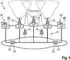
- Figure 1 shows a radio system 10 for air traffic control (ATC) of a respective airspace.
- ATC air traffic control
- the radio system 10 comprises three main radios 12, two standby radios 14 as well as two voice communication systems 16.
- the voice communication systems 16 are established by a cloud-based server structure.
- the respective radios 12, 14 are established by Internet Protocol based radios, namely IP-based radios.
- the radios 12, 14 are connected with the voice communication systems 16 by means of an Internet Protocol infrastructure 18, for instance a Wide Area Network (WAN).
- Internet Protocol infrastructure for instance a Wide Area Network (WAN).
- the main radios 12 are active for establishing a radio communication with another entity, for instance an aircraft within the airspace controlled.
- the standby radios 14 are inactive which means that these radios 14 are not used for establishing a respective radio communication.
- At least one of the voice communication systems 16, particularly each of the voice communication systems 16, is configured to monitor the respective status of the radios 12, 14 in order to retrieve information whether or not the respective radio 12, 14 is active or rather inactive.
- the main radios 12 and the standby radios 14 are redundant which means that they are configured in a similar manner such that the standby radio 14 can be used instead of one of the main radios 12 provided that failure concerning the main radio 12 occurs.
- the voice communication system 16 is also configured to receive a failure report in case of a failure that is associated with one of the main radios 12.
- the respective failure report is forwarded by means of a message associated with a remote radio control (RRC) protocol.
- RRC remote radio control
- the voice communication system 16 is enabled to process the failure report received internally.
- the voice communication system 16 activates a respective inactive standby radio 14 automatically while receiving the failure report associated with one of the main radios 12 such that the radio channel availability can be ensured even though one of the main radios 12 has to be deactivated due to a failure associated therewith.
- the failure report may be issued by one of the main radios 14 itself that forwards the failure report to the voice communication system 16. This can be ensured provided that the occurring failure is a minor one that still allows the main radio 12 to communicate with the voice communication system 16.
- the radio system 10 comprises a monitoring module 20 that might be associated with the voice communication system 16.
- the monitoring module 20 may identify a respective failure associated with one of the main radios 12 such that it forwards the failure report to the voice communication system 16. Provided that the monitoring module 20 is integrated within the voice communication system 16, the respective failure report is forwarded internally within the voice communication system 16.
- the monitoring module 20 is enabled to identify a connection error, particularly a connection error associated with the IP infrastructure 18, which might cause a communication interruption between the voice communication system 16 and the respective main radio 12.
- the monitoring module 20 may identify a total failure of the respective main radio 12 that might disable the main radio 12 to communicate its internal failure to the voice communication system 16 appropriately.
- the respective main failure or rather the network communication failure may be assigned to an absence of a status report of the main radio 12.
- the respective status report may be associated with a status report that is issued automatically due to a predefined reporting scheme.
- the failure may also be detected provided that the voice communication system 16 requests a status report of the respective main radio 12 without receiving a response from the main radio 12.
- the respective radios 12, 14 are directly connected with the voice communication system 16, namely the cloud-based server structure, by means of connection lines associated with the IP infrastructure 18. Hence, an intervening radio gateway is not provided that would be located between the voice communication system 16 and the respective radio 12, 14.
- the radio system 10 comprises a control interface 22 that may be located at a controller working position.
- An operator for instance an air traffic controller, is enabled to manually switch between a respective main radio 12 and a respective standby radio 14, thereby activating the respective radio switched to.
- the air traffic controller may initiate a switchover from a respective main radio 12 to a respective standby radio 14 in a manual manner by controlling the radio system 10 appropriately.
- the switchover command issued via the control interface 22 is processed internally by means of the voice communication system 16 which in turn sends the respective command to the radios 12, 14.
- the radios 12, 14 communicate their respective status to the voice communication system 16, particularly after performing a switchover command received.
- the respective voice communication system 16 are interconnected with each other such that the information with regard to the switchover performed is shared among the voice communication systems 16 appropriately such that all voice communication systems 16 may be informed about the respective status of the radios 12, 14.
- the voice communication systems 16 are also informed about any failure associated with any of the main radios 12 since the failure reports are also shared among the voice communication systems.
- VCSs 16 are shown that are labelled with VCS1 and VCS2.
- a first radio labelled with radio A and a second radio labelled with radio B are shown which might correspond to the main radio and the standby radio depending on their respective status, namely active or inactive.
- a session initiation protocol (SIP) session 1 is initiated by the first VCS 16 labelled with VCS1, wherein the respective radios 12, 14 response to the initiation by transmitting their respective status (status reporting).
- SIP session initiation protocol
- radio A is active such that it corresponds to the main radio 12
- radio B is inactive such that it corresponds to the standby radio 14.
- both radios 12, 14 transmit different symbols/bits, namely "0" or rather “1", which indicate their respective status.
- the symbols/bits are forwarded to the first VCS 16, namely VCS1, in a real-time transport protocol (RTP) header extension.
- RTP real-time transport protocol
- the status reporting may be repeated according to a scheme, for instance 10 times, 20 times or continuously, wherein the corresponding symbols/bits are transmitted in each packet transmitted, particularly each RTP packet, until the maximum number (e.g. 10 or 20) has been reached.
- a scheme for instance 10 times, 20 times or continuously, wherein the corresponding symbols/bits are transmitted in each packet transmitted, particularly each RTP packet, until the maximum number (e.g. 10 or 20) has been reached.
- a second session initiation protocol (SIP) session 2 is initiated by the second VCS 16 labelled with VCS2, wherein the respective radios 12, 14 response to the initiation by transmitting their respective status (status reporting) in a similar manner as described above.
- SIP session initiation protocol
- VCSs 16 may also request the respective status of the radios 12, 14 (status request).
- the VCSs 16 forwards the last known status of the respective radios 12, 14 towards the radios 12, 14, wherein the last known status is transmitted by means of the symbols/bits, for instance "0" or "1".
- the radios 12, 14 respond to the request by a respective status reporting as described above.
- the radio system 10 issues an alarm or an alert while assuming that the respective radio 12, 14 not responding has a major failure and/or the IP connection is disturbed.
- the radio(s) 12, 14 may trigger a switchover or rather the switchover is triggered externally, for instance manually via the control interface 22.
- the first radio labelled with "A” became inactive, namely the standby radio 14, whereas the second radio labelled with "B” became active, namely the main radio 12.
- the radios 12, 14 report the change of status to all active SIP sessions, namely all VCSs 16 connected by forwarding their new status by means of the respective symbols/bits.
- one of the VCSs 16 may also trigger the switchover automatically provided that a failure report of the main radio 12 or rather the monitoring module 20 was received.
- the second VCS 16 labelled with "VCS2" commands the switchover by forwarding a respective message with the RTP header extension comprising the respective bit indicating the new status of the radios 12, 14, causing the switchover.
- the main radio 12 becomes the standby radio 14 and vice versa.
- the radios 12, 14 perform the status reporting as described above while transmitting the status to all VCSs 16 connected, namely all active SIP sessions.
- the automatic switchover triggered by one of the VCS 16 may also be rejected provided that one of the radios 12, 14 has a NO-GO status associated with a failure of the respective radio 12, 14.
- the commands forwarded from the VCS 16 to the radios are rejected by reporting their former and still actual status to the VCS 16 requesting the switchover.
- the radios 12, 14 are not able to perform the switchover due to the occurring failure.
- each connected VCS 16 can request the current status of the radios 12, 14 by sending to the radios 12, 14 the last known status in the RRC RTPTx header extension.
- the radios 12, 14 reply the current status to the requesting VCS 16 according to the setting of the status reporting repetition counter in every RTP/R2S packet.
- the VCS 16 does not receive the answer in a configurable time, it shall initiate another status request to the radios 12, 14.
- the symbols/bits "MSTxF1" indicating the control of a transmitting radio (Tx) is used to command from the VCS 16 a radio switching (on the RTPTx header, from VCS 16 to radios 12, 14) and to report back to the current status of the radios 12, 14 (on the RTPRx header, from radios 12, 14 to VCS 16).
- the respective radio(s) 12, 14 may also correspond to receiving radios (Rx).
- the symbols/bits "MSRxF1" would be used appropriately.
- the manual switchover may require a precondition to be fulfilled. For instance, it is required that the requesting VCS 16 is successfully synchronized with the radios 12, 14, i.e. the radio status is known and/or that the radios 12, 14 are not in the NO-GO status.
- the radio system 10 In case a manual switchover is requested, the radio system 10, particularly the respective VCS 16, sends in the RRC extension of the RTPTx Header the appropriate MSTxF1 and/or MSRxF1 values.
- the standby radio 14 may check the MSTxF1 and/or MSRxF1 value. The previously main radio 12 may ignore the switching command.
- the VCS 16 shall wait for the confirmation from the radios 12, 14 for successful switching before sending any new command. In case the confirmation is not received within a defined time, the VCS 16 resends the switchover command for a maximum configurable number of retries.
- Both radios 12, 14 report to the VCS 16 the new status via RRC header extension as described above. This report will be repeated from the radios 12, 14 to each connected SIP session, namely each VCS 16 connected, according to the setting of the status reporting repetition counter in every RTP/R2S packet.
- the radios 12, 14 have an activatable remote radio control module, enabling the respective remote radio control functionality to be activated or rather deactivated.
- the respective functionality may be enabled/disabled via a specific configuration parameter such that a reboot of the respective radio 12, 14 might be necessary to change the configuration appropriately.
- the RRC RTP header extension comprising the symbol(s)/bit(s) are always sent, independent of other configuration parameters.
Landscapes
- Engineering & Computer Science (AREA)
- Aviation & Aerospace Engineering (AREA)
- Physics & Mathematics (AREA)
- General Physics & Mathematics (AREA)
- Computer Networks & Wireless Communication (AREA)
- Signal Processing (AREA)
- Mobile Radio Communication Systems (AREA)
Abstract
Description
- The invention relates to a radio system for air traffic control (ATC). Further, the invention relates to a method of controlling a radio system for air traffic control (ATC).
- In the state of the art, radio systems used for air traffic control (ATC) are known that are used by at least one air service navigation provider (ANSP) for controlling a respective airspace. The radio systems used comprise a main radio as well as a standby radio for each frequency deployed, wherein the standby radio is activated in case of failure associated with the main radio. This means that a failure occurs which causes the use of the standby radio instead of the main radio for radio communication, particularly with an aircraft with in the airspace controlled by the respective ANSP.
- So far, the radio systems use messages associated with several different protocols for switching from the main radio to the respective standby radio and for gathering the status of the radios in order to identify a respective failure associated with the main radio. Typically, a session initiation protocol (SIP) is used for initiating, maintaining and terminating real-time sessions, which is associated with a real-time transport protocol (RTP). Hence, the SIP with RTP can be used for manually switching between the respective radios. In addition, a simple network management protocol (SNMP) or a proprietary protocol like GB2PP is used for reading the respective status of the respective radio, which however requires additional hardware, for instance a gateway.
- Accordingly, at least two different protocols have to be handled by the radio system for controlling the respective radios of the radio system. However, this results in high efforts in order to align the messages associated with the different protocols in time. Furthermore, the costs are increased due to the additional hardware needed.
- Accordingly, there is a need for a simplified radio system as well as a method of controlling such a radio system which enables radio redundancy and a high radio communication channel availability.
- The invention provides a radio system for air traffic control (ATC), wherein the radio system comprises at least one main radio, at least one standby radio and at least one voice communication system (VCS). The radio system has a default operation mode in which the main radio is active and the standby radio is inactive. The voice communication system is configured to monitor the status of the main radio and to monitor the status of the standby radio. The main radio and the standby radio are established by an internet protocol based radio. Further, the voice communication system is configured to receive a failure report in case of a failure associated with the main radio by means of a remote radio control (RRC) protocol. Furthermore, the voice communication system is configured to process the failure report received and to activate the inactive standby radio automatically by means of a remote radio control protocol.
- Further, the invention provides a method of controlling a radio system for air traffic control. The method comprises the steps of:
- identifying a failure associated with an active main radio, wherein the main radio is established by an internet protocol based radio,
- issuing a failure report in case of the identified failure by means of a remote radio control protocol,
- receiving the failure report by means of a voice communication system,
- processing the failure report received by means of the voice communication system, and
- activating an inactive standby radio automatically by means of a remote radio control protocol via the voice communication system, wherein the standby radio is established by an internet protocol based radio.
- Accordingly, a radio system as well as a method of controlling the radio system are provided that ensure an automatic redundancy of the radio system which is based on remote radio control (RRC) functionality, also called radio remote control functionality. The radio switching, namely the switching between the main radio and the standby radio, as well as any status reporting of the respective radios can be provided by means of messages associated with a single protocol, namely the respective RRC protocol, such that former problems associated with handling two different protocols are overcome appropriately.
- The respective radios are established by IP-based radios such that these radios can receive and transmit messages directly by means of a single protocol. Further, these radios have a dedicated IP address such that they can be addressed appropriately. Voice signals can be exchanged via the radio system, for instance air-ground communication or ground-ground communication, which relate to Voice over Internet Protocol (VoIP) technology.
- In general, a high radio communication channel availability of the radio system is achieved since the standby radio is activated in case of a failure associated with the main radio automatically.
- In fact, the voice communication system is configured to make the decision in an automatic manner if the main radio or rather the standby radio is to be used for radio communication depending on the status of the respective radios, particularly any failure report received.
- Put differently, the voice communication system directly and automatically commands a radio switching (from VCS to radios). Furthermore, the radios report back their respective status to the voice communication system (from radios to VCS).
- Generally, the respective radio, namely the main radio and/or the standby radio, may be a receiving radio (receiver), a transmitting radio (transmitter), or a transmitting and receiving radio (transceiver). The transceiver may comprise a receiving module and a transmitting module in one housing.
- The main radio and the standby radio are redundant which means that they are configured in a similar manner such that the standby radio can be used instead of the main radio in case of failure associated with the main radio.
- An aspect provides that the main radio itself is configured to forward the failure report to the voice communication system. Hence, the main radio itself detects the failure and forwards the failure report to the voice communication system. Put differently, the main radio can identify the respective failure that is associated with itself such that the main radio informs the voice communication system appropriately, thereby indirectly causing the voice communication system to initiate a switchover from the main radio to the standby radio. However, the main radio does not transmit a respective request to initiate the switchover since the main radio only forwards the respective information, namely the failure report, that is processed internally by the voice communication system, which results in commanding the switchover.
- Another aspect provides that the radio system comprises a monitoring module that is configured to forward the failure report to the voice communication system. Particularly, the monitoring module is configured to detect a connection error of the main radio and/or a total failure of the main radio. Thus, the monitoring module may be formed separately with respect to the main radio such that a total failure of the main radio can still be detected by means of the monitoring module. The total failure may disable the main radio to communicate with the voice communication system, particularly reporting its status or rather any failure.
- Furthermore, the monitoring module may detect any failure associated with the connection of the main radio to the voice communication system which in turn effects that the voice communication system cannot receive any information from the main radio.
- Hence, the failure associated with the main radio may relate to a total failure of the main radio itself, a minor failure of the main radio that still allows the main radio to communicate with the voice communication system and/or a (network) connection error that might interrupt the communication between the main radio and the voice communication system.
- The monitoring module may be part of the voice communication system that processes messages and/or reports exchanged between the voice communication system and the main radio in order to retrieve any information with regard to an occurring failure. For instance, absence of certain messages might be regarded as a network connection failure, indicating that the connection to the main radio is interrupted, or a major failure of the main radio which disables the main radio to communicate the respective message(s). Thus, the voice communication system is configured to take appropriate actions, for instance issuing an alarm or an alert as well as a switchover to the standby radio.
- In case of a failure that is also associated with the standby radio, the voice communication system might issue an alert or an alarm in any case. Further, those failures also involving the standby radio do not trigger a switch-over from the main radio to the standby radio.
- As mentioned above, the voice communication system is configured to monitor the status of both radios, namely the main radio as well as the standby radio. Accordingly, the voice communication system is always informed about the respective status of the radios such that the automatic switchover can be initiated automatically.
- Furthermore, the voice communication system is connected with the main radio and/or the standby radio by means of an Internet Protocol (IP) infrastructure. The IP infrastructure may relate to a wide area network (WAN).
- In fact, a wide area network (WAN) relates to computer networking technologies used to transmit data or information over long distances, and between different LANs, MANs and other localized computer networking architectures. Hence, WANs are used to connect LANs and other types of networks together so that users and computers in one location can communicate with users and computers in other locations. Many WANs are built for one particular organization and are private. Others, built by Internet service providers, provide connections from an organization's LAN to the Internet.
- The main radio and/or the standby radio are/is directly connected with the voice communication system via a connection line, particularly without an intervening radio gateway. The VCS and the radios can communicate directly with each other due to the RRC protocol used. The connection line may be established by an Ethernet connection. Therefore, the VCS can directly command the switchover without any intervening device like a radio gateway. Furthermore, the radios can report their status directly to the VCS.
- According to another aspect, the main radio and/or the standby radio are/is configured to report the respective status, particularly periodically and/or according to a pre-defined scheme. This scheme may be started once a status change has been commanded. For instance, the respective radio repeats the status reporting messages to the VCS in every packet, particularly RTP packet, until a maximum number has been reached which is defined in a status reporting repetition counter provided by the scheme applied, for
instance - Accordingly, the voice communication system is informed about the respective status of the radios of the radio system. The status reports are forwarded to the voice communication system automatically according to the respective scheme that is inter alia initiated after each switchover.
- Furthermore, the voice communication system is enabled to trigger a status report by transmitting a message associated with the remote radio control protocol, indicating the status stored (last known status) according to the last status report received from the respective radio. The radio(s) may reply to the respective request appropriately by transmitting the actual status.
- In addition, the radio system may comprise a control interface via which an operator is enabled to manually switch between the main radio and the standby radio, thereby activating the respective radio switched to. The radio system enables a manual switchover between the radios of the radio system. This manual switchover is triggered by the voice communication system provided that preconditions are fulfilled, for instance a successfully synchronized voice communication system with the respective radios. This means that the requesting voice communication system is aware of the respective status of the radios involved. A precondition may also relate to the fact that the radios involved are not in a status indicating a failure, which may also be called No-Go status.
- If the operator requests a manual switchover, the voice communication systems sends a message associated with the remote radio control protocol to the radios involved. The switchover may be triggered by the standby radio, namely the inactive radio, such that only the standby radio checks the respective message received. The previously main radio, namely the active radio, ignores the respective switching command received.
- Afterwards, a confirmation concerning the successful switching is forwarded to the voice communication system that awaits the respective confirmation before sending any further commands. If the confirmation is not received within a defined time, the voice communication system resends the switchover command for a predefined number of retries. The predefined number of retries may be configurable.
- In case the radio is receiving a switchover command from the VCS, a status request or manual switchover command via the control interface, the radio shall react accordingly and restart its status reporting repetition counter such that the respective status is reported periodically and/or according to a pre-defined scheme. As already mentioned, the respective radio repeats the status reporting messages to the VCS in every packet sent, particularly in every RTP packet, until a maximum number has been reached which is defined in the status reporting repetition counter, for
instance - Another aspect provides that the voice communication system is established by a dedicated hardware device or a cloud-based server structure. The voice communication system may be a standalone device that is associated with a single air navigation service provider (ANSP).
- Alternatively, the voice communication system may be implemented in a cloud-based manner such that several ANSPs may share a common voice communication system and/or radio system.
- Generally, the cloud-based server structure may provide applications, also called programs, which are typically used by air traffic controllers at their controller working positions. Put differently, the respective applications run on the cloud-based server structure such that the controller working position may comprise output devices that output the respective information provided by the cloud-based server structure, particularly the applications running on the cloud-based server structure. Therefore, it is not necessary that each controller working position is equipped with expensive hardware in order to provide the necessary computational power that is required for running the applications. In addition, the same applications can be used at different locations, particularly controller working positions at different locations, by simply connecting to the cloud-based server structure via the IP infrastructure.
- Generally, the cloud-based server structure concerns a data center that consists of hardware (components). The respective cloud-based server structure may relate to a central server structure or rather a distributed server structure with several distributed hardware components that are connected with each other by means of the IP infrastructure. The different hardware components distributed may be connected to the same IP network, namely the wide area network.
- However, the hardware (components) of the cloud-based server structure is located at a different location compared to the respective controller working position. Particularly, the hardware (components) of the cloud-based server structure is located at a different location compared to any controller working position connected via the internet protocol infrastructure.
- Since the respective applications (as well as data associated therewith) is provided by the cloud-based server structure, different entities having access to the cloud-based server structure can use them. Accordingly, the associated costs can be shared between the participating entities appropriately.
- For instance, several air navigation service providers may use a common cloud-based server structure.
- Moreover, the radio system may comprise several voice communication systems, wherein the radio system is configured to automatically inform these voice communication systems concerning the failure associated with the main radio. Thus, all voice communication systems of the radio system are informed appropriately that the main radio is not active anymore. This ensures that all voice communication systems that might be assigned to different air navigation service providers are up to date.
- Generally, the radio system may comprise several main radios and several standby radios. Particularly, the number of main radios and the number of standby radios are different. For instance, m main radios and n standby radios are provided, wherein m does not equal n. Hence, the standby radios are not each associated to a certain main radio in an unambiguous manner such that one of the several standby radios is activated provided that one of the several main radios has a failure. In fact, one of the several, namely n, standby radios is activated in case that one of the several, namely m, main radios fails.
- Alternatively, several radio pairs are provided, each comprising one main radio and one standby radio associated to the respective main radio. Thus, each main radio has a dedicated standby radio that is used in case of failure of the respective main radio.
- Another aspect provides that the communication system is configured to control the main radio and/or the standby radio by means of a control symbol in a real-time transport protocol (RTP) header extension and/or in that the respective radio is configured to report its status by means of a control symbol in a real-time transport protocol (RTP) header extension. The control symbol may correspond to a control bit. Hence, respective symbols or rather bits can be used to command from the voice communication system a main radio or rather a standby radio, particularly the respective switch-over. The respective symbols or rather bits are associated with the RTP header since they relate to a respective RTP header extension. In a similar manner, the radios report back their current status to the voice communication system by means of the RTP header, wherein the information is associated with the respective symbol or rather bit.
- In a simple example, the status activate is associated with a "0", whereas the status inactive is associated with a "1" provided that the control symbol corresponds to a control bit.
- The respective control symbol or rather control bit may be associated with "MSTxFI" or rather "MSRxF1", wherein MS represents "Main" and "Standby", Tx represents "transmitting radio", Rx represents "receiving radio", and F1 represents a frequency used or rather a respective frequency channel.
- In case of a transceiver, both symbols or rather bits shall be used. All other bits and bytes or rather symbols defined in the RRC feature shall be ignored by the radio.
- In case of a transmitter with transmitting module and receiving module in one housing, if only one module fails or receives a command to switch, then both modules shall be switched such that the transceiver as one device can either be main or standby only.
- Another aspect provides that the main radio and/or the standby radio have/has an activatable remote radio control module, enabling a remote radio control functionality to be activated or rather deactivated. Therefore, the RRC functionality of the respective radio may be activated or rather deactivated by an operator of the radio system. The functionality can be enabled/disabled via a specific configuration parameter. A reboot of the radio might be necessary to change the configuration appropriately.
- Generally, it shall be possible to activate/deactivate the functionality, to set the status reporting repetition counter to the values "10", "20", "30", "continuous" and so on.
- In case the RRC functionality is enabled the RRC RTP header extension are always sent, independent of other configuration parameter.
- Accordingly, the respective radios are configured and connected for automatic switchover. It is ensured that only one radio at a time is main, namely active, and that the switchover is properly commanded.
- As mentioned above, the radio system may comprise several voice communication systems. However, the radios shall report the current status to all connected VCSs via the respective control symbol of the RRC extension on their header.
- The respective reporting is only active if the functionality is enabled.
- The radios shall start reporting their status to a connected VCS under the following conditions: session start-up (to the connecting VCS), status request (to the requesting VCS), switchover commanded (to all connected VCS) and/or status change of radio (to all connected VCS).
- As mentioned above, the radios repeat the status reporting messages to the respective VCS in every RTP/R2S packet, until the maximum number has been reached, as defined in the configured status reporting repetition counter.
- The VCS and the radios connect with each other by session initiation protocol (SIP), namely a SIP session start-up.
- When the functionality is enabled and the radios accept a SIP invitation from a respective VCS, the radios start sending their current activation status via the RRC RTP header extension to the connected VCS in every RTP/R2S packet. As already discussed, a maximum number of repetitions is provided according to the configured status reporting repetition counter.
- In case the radio is receiving a radio switchover command, a status request or manual switchover command, the radios react accordingly and restart the status reporting repetition counter.
- The procedure is applicable for each connected VCS via a respective SIP session.
- Moreover, in case a radio with disabled RRC functionality receives from a connected VCS audio or R2S RTP packets containing RRC header extensions, the radio shall discard the additional information contained in the not relevant RTP header extension and shall continue to operate normally, according to its configuration.
- In case of both radios, namely the main radio and the standby radio, sending the same activation status to the VCS, the VCS can detect the inconsistent status and shall raise an alarm.
- In case a VCS, not supporting the RRC functionality, connects to a radio with the RRC function activated, the VCS receives from the radio audio or R2S RTP packets containing RRC header extensions, reporting the current activation status of the radio. The VCS shall tolerate the RRC header extension and ignore its content. However, it has to be ensured by the ANSP that the VCS, not supporting the RRC function, is timely informed by any other means about the radio switchover triggered by RRC command. Time differences between real time RRC and other protocols have to be considered in the operational environment.
- The respective aspects mentioned above apply to the radio system as well as to the method of controlling a radio system appropriately.
- Further aspects and advantages of the claimed subject matter will become more readily appreciated as the same become better understood by reference to the following detailed description, when taken in conjunction with the accompanying drawings, wherein:
-
Figure 1 schematically shows a radio system according to the invention, and -
Figure 2 schematically shows a flow diagram illustrating different scenarios of the radio system. -
Figure 1 shows aradio system 10 for air traffic control (ATC) of a respective airspace. - In the shown embodiment, the
radio system 10 comprises threemain radios 12, twostandby radios 14 as well as twovoice communication systems 16. - The
voice communication systems 16 are established by a cloud-based server structure. Therespective radios - Accordingly, the
radios voice communication systems 16 by means of anInternet Protocol infrastructure 18, for instance a Wide Area Network (WAN). - In a default operation mode of the
radio system 10, themain radios 12 are active for establishing a radio communication with another entity, for instance an aircraft within the airspace controlled. Thestandby radios 14 are inactive which means that theseradios 14 are not used for establishing a respective radio communication. - Furthermore, at least one of the
voice communication systems 16, particularly each of thevoice communication systems 16, is configured to monitor the respective status of theradios respective radio - Usually, the
main radios 12 and thestandby radios 14 are redundant which means that they are configured in a similar manner such that thestandby radio 14 can be used instead of one of themain radios 12 provided that failure concerning themain radio 12 occurs. - For this purpose, the
voice communication system 16 is also configured to receive a failure report in case of a failure that is associated with one of themain radios 12. The respective failure report is forwarded by means of a message associated with a remote radio control (RRC) protocol. - The
voice communication system 16 is enabled to process the failure report received internally. - Furthermore, the
voice communication system 16 activates a respectiveinactive standby radio 14 automatically while receiving the failure report associated with one of themain radios 12 such that the radio channel availability can be ensured even though one of themain radios 12 has to be deactivated due to a failure associated therewith. - In general, the failure report may be issued by one of the
main radios 14 itself that forwards the failure report to thevoice communication system 16. This can be ensured provided that the occurring failure is a minor one that still allows themain radio 12 to communicate with thevoice communication system 16. - Alternatively or additionally, the
radio system 10 comprises amonitoring module 20 that might be associated with thevoice communication system 16. - The
monitoring module 20 may identify a respective failure associated with one of themain radios 12 such that it forwards the failure report to thevoice communication system 16. Provided that themonitoring module 20 is integrated within thevoice communication system 16, the respective failure report is forwarded internally within thevoice communication system 16. - In fact, the
monitoring module 20 is enabled to identify a connection error, particularly a connection error associated with theIP infrastructure 18, which might cause a communication interruption between thevoice communication system 16 and the respectivemain radio 12. - Furthermore, the
monitoring module 20 may identify a total failure of the respectivemain radio 12 that might disable themain radio 12 to communicate its internal failure to thevoice communication system 16 appropriately. For instance, the respective main failure or rather the network communication failure may be assigned to an absence of a status report of themain radio 12. The respective status report may be associated with a status report that is issued automatically due to a predefined reporting scheme. - However, the failure may also be detected provided that the
voice communication system 16 requests a status report of the respectivemain radio 12 without receiving a response from themain radio 12. - As shown in
Figure 1 , therespective radios voice communication system 16, namely the cloud-based server structure, by means of connection lines associated with theIP infrastructure 18. Hence, an intervening radio gateway is not provided that would be located between thevoice communication system 16 and therespective radio - In addition, the
radio system 10 comprises acontrol interface 22 that may be located at a controller working position. An operator, for instance an air traffic controller, is enabled to manually switch between a respectivemain radio 12 and arespective standby radio 14, thereby activating the respective radio switched to. - Thus, the air traffic controller may initiate a switchover from a respective
main radio 12 to arespective standby radio 14 in a manual manner by controlling theradio system 10 appropriately. The switchover command issued via thecontrol interface 22 is processed internally by means of thevoice communication system 16 which in turn sends the respective command to theradios - As mentioned above, the
radios voice communication system 16, particularly after performing a switchover command received. - The respective
voice communication system 16 are interconnected with each other such that the information with regard to the switchover performed is shared among thevoice communication systems 16 appropriately such that allvoice communication systems 16 may be informed about the respective status of theradios - Accordingly, the
voice communication systems 16 are also informed about any failure associated with any of themain radios 12 since the failure reports are also shared among the voice communication systems. - Hereinafter, different scenarios of the
radio system 10 are described in more detail while referring toFigure 2 . - In
Figure 2 , twoVCSs 16 are shown that are labelled with VCS1 and VCS2. In addition, a first radio labelled with radio A and a second radio labelled with radio B are shown which might correspond to the main radio and the standby radio depending on their respective status, namely active or inactive. - At the beginning a session initiation protocol (SIP)
session 1 is initiated by thefirst VCS 16 labelled with VCS1, wherein therespective radios - In the shown embodiment, radio A is active such that it corresponds to the
main radio 12, whereas radio B is inactive such that it corresponds to thestandby radio 14. - Accordingly, both
radios first VCS 16, namely VCS1, in a real-time transport protocol (RTP) header extension. - The status reporting may be repeated according to a scheme, for
instance 10 times, 20 times or continuously, wherein the corresponding symbols/bits are transmitted in each packet transmitted, particularly each RTP packet, until the maximum number (e.g. 10 or 20) has been reached. - Further, a second session initiation protocol (SIP)
session 2 is initiated by thesecond VCS 16 labelled with VCS2, wherein therespective radios - Furthermore, the
VCSs 16 may also request the respective status of theradios 12, 14 (status request). - For this purpose, the
VCSs 16 forwards the last known status of therespective radios radios - The
radios - Should the
respective VCS 16 not receive any status reporting from one of theradios radio system 10 issues an alarm or an alert while assuming that therespective radio - Moreover, the radio(s) 12, 14 may trigger a switchover or rather the switchover is triggered externally, for instance manually via the
control interface 22. - As shown, the first radio labelled with "A" became inactive, namely the
standby radio 14, whereas the second radio labelled with "B" became active, namely themain radio 12. - The
radios VCSs 16 connected by forwarding their new status by means of the respective symbols/bits. - Again, the status reporting of the radios after the externally triggered or rather manually issued switchover is done according to the respective scheme as already described above.
- Furthermore, one of the
VCSs 16 may also trigger the switchover automatically provided that a failure report of themain radio 12 or rather themonitoring module 20 was received. - For instance, the
second VCS 16 labelled with "VCS2" commands the switchover by forwarding a respective message with the RTP header extension comprising the respective bit indicating the new status of theradios - Hence, the
main radio 12 becomes thestandby radio 14 and vice versa. - Afterwards, the
radios VCSs 16 connected, namely all active SIP sessions. - The automatic switchover triggered by one of the
VCS 16 may also be rejected provided that one of theradios respective radio - Accordingly, the commands forwarded from the
VCS 16 to the radios are rejected by reporting their former and still actual status to theVCS 16 requesting the switchover. Put differently, theradios - In fact, each
connected VCS 16 can request the current status of theradios radios radios VCS 16 according to the setting of the status reporting repetition counter in every RTP/R2S packet. In case theVCS 16 does not receive the answer in a configurable time, it shall initiate another status request to theradios - However, a missing answer from one of the
radios VCS 16. - In case the last known radio status at the
VCS 16 does not match the actual status of theradios VCS 16 as described above. - As shown in
Figure 2 , the symbols/bits "MSTxF1", indicating the control of a transmitting radio (Tx), is used to command from the VCS 16 a radio switching (on the RTPTx header, fromVCS 16 toradios 12, 14) and to report back to the current status of theradios 12, 14 (on the RTPRx header, fromradios - The manual switchover may require a precondition to be fulfilled. For instance, it is required that the requesting
VCS 16 is successfully synchronized with theradios radios - In case a manual switchover is requested, the
radio system 10, particularly therespective VCS 16, sends in the RRC extension of the RTPTx Header the appropriate MSTxF1 and/or MSRxF1 values. - As the switchover is triggered by the
standby radio 14, only thestandby radio 14 may check the MSTxF1 and/or MSRxF1 value. The previouslymain radio 12 may ignore the switching command. - To prevent instable status, the
VCS 16 shall wait for the confirmation from theradios VCS 16 resends the switchover command for a maximum configurable number of retries. - In case the
standby radio 14 detects in the RTPTx header the MSTxF1 and/or MSRxF1 = 0, it triggers an internal "SKIP_TO_GO" event, leading to a radio swichover. - Both
radios VCS 16 the new status via RRC header extension as described above. This report will be repeated from theradios VCS 16 connected, according to the setting of the status reporting repetition counter in every RTP/R2S packet. - Generally, the
radios respective radio - In case the RRC functionality is enabled the RRC RTP header extension comprising the symbol(s)/bit(s) are always sent, independent of other configuration parameters.
Claims (15)
- A radio system for air traffic control (ATC), wherein the radio system comprises at least one main radio (12), at least one standby radio (14) and at least one voice communication system (16), wherein the radio system (10) has a default operation mode in which the main radio (12) is active and the standby radio (14) is inactive, and wherein the voice communication system (16) is configured to monitor the status of the main radio (12) and to monitor the status of the standby radio (14), characterized in that the main radio (12) and the standby radio (14) are established by an internet protocol based radio, wherein the voice communication system (16) is configured to receive a failure report in case of a failure associated with the main radio (12) by means of a remote radio control (RRC) protocol, and wherein the voice communication system (16) is configured to process the failure report received and to activate the inactive standby radio (14) automatically by means of a remote radio control (RRC) protocol.
- The radio system according to claim 1, characterized in that the main radio (12) itself is configured to forward the failure report to the voice communication system (16).
- The radio system according to claim 1 or 2, characterized in that the radio system (10) comprises a monitoring module (20) that is configured to forward the failure report to the voice communication system (16), in particular wherein the monitoring module (20) is configured to detect a connection error of the main radio (12) and/or a total failure of the main radio (12).
- The radio system according to any of the preceding claims, characterized in that the voice communication system (16) is connected with the main radio (12) and/or the standby radio (14) by means of an internet protocol infrastructure (18).
- The radio system according to any of the preceding claims, characterized in that the main radio (12) and/or the standby radio (14) are/is directly connected with the voice communication system (16) via a connection line, particularly without an intervening radio gateway.
- The radio system according to any of the preceding claims, characterized in that the main radio (12) and/or the standby radio (14) are/is configured to report the respective status, particularly periodically and/or according to a pre-defined scheme.
- The radio system according to any of the preceding claims, characterized in that the radio system (10) comprises a control interface (22) via which an operator is enabled to manually switch between the main radio (12) and the standby radio (14), thereby activating the respective radio (12, 14) switched to.
- The radio system according to any of the preceding claims, characterized in that the voice communication system (16) is established by a dedicated hardware device or a cloud-based server structure.
- The radio system according to any of the preceding claims, characterized in that the radio system (10) comprises several voice communication systems (16), wherein the radio system (10) is configured to automatically inform these voice communication systems (16) concerning the failure associated with the main radio (12).
- The radio system according to any of the preceding claims, characterized in that the radio system (10) comprises several main radios (12) and several standby radios (14), in particular wherein the number of main radios (12) and the number of standby radios (14) are different or wherein several radio pairs are provided, each comprising one main radio (12) and one standby radio (14) associated to the respective main radio (12).
- The radio system according to any of the preceding claims, characterized in that the voice communication system (16) is configured to control the main radio (12) and/or the standby radio (14) by means of a control symbol in a real-time transport protocol (RTP) header extension and/or in that the respective radio (12, 14) is configured to report its status by means of a control symbol in a real-time transport protocol (RTP) header extension, in particular wherein the control symbol corresponds to a control bit.
- The radio system according to any of the preceding claims, characterized in that the main radio (12) and/or the standby radio (14) have/has an activatable remote radio control (RRC) module, enabling a remote radio control (RRC) functionality to be activated or rather deactivated.
- A method of controlling a radio system for air traffic control (ATC), comprising the steps of:- Identifying a failure associated with an active main radio (12), wherein the main radio (12) is established by an internet protocol based radio,- Issuing a failure report in case of the identified failure by means of a remote radio control (RRC) protocol,- Receiving the failure report by means of a voice communication system (16),- Processing the failure report received by means of the voice communication system (16), and- Activating an inactive standby radio (14) automatically by means of the voice communication system (16), wherein the standby radio (16) is established by an internet protocol based radio.
- The method according to claim 13, characterized in that the failure is identified by the main radio (12) itself and/or a monitoring module (20).
- The method according to claim 13 or 14, characterized in that the failure report is issued by the main radio (12) itself and/or the monitoring module (20).
Priority Applications (2)
| Application Number | Priority Date | Filing Date | Title |
|---|---|---|---|
| ES20173021T ES3023567T3 (en) | 2020-05-05 | 2020-05-05 | Radio system for air traffic control and method of controlling a radio system for air traffic control |
| EP20173021.5A EP3908030B1 (en) | 2020-05-05 | 2020-05-05 | Radio system for air traffic control and method of controlling a radio system for air traffic control |
Applications Claiming Priority (1)
| Application Number | Priority Date | Filing Date | Title |
|---|---|---|---|
| EP20173021.5A EP3908030B1 (en) | 2020-05-05 | 2020-05-05 | Radio system for air traffic control and method of controlling a radio system for air traffic control |
Publications (2)
| Publication Number | Publication Date |
|---|---|
| EP3908030A1 true EP3908030A1 (en) | 2021-11-10 |
| EP3908030B1 EP3908030B1 (en) | 2025-03-19 |
Family
ID=70553918
Family Applications (1)
| Application Number | Title | Priority Date | Filing Date |
|---|---|---|---|
| EP20173021.5A Active EP3908030B1 (en) | 2020-05-05 | 2020-05-05 | Radio system for air traffic control and method of controlling a radio system for air traffic control |
Country Status (2)
| Country | Link |
|---|---|
| EP (1) | EP3908030B1 (en) |
| ES (1) | ES3023567T3 (en) |
Cited By (1)
| Publication number | Priority date | Publication date | Assignee | Title |
|---|---|---|---|---|
| EP4239978A1 (en) * | 2022-03-04 | 2023-09-06 | Rohde & Schwarz GmbH & Co. KG | Air traffic control system and method of performing a switchover |
Citations (1)
| Publication number | Priority date | Publication date | Assignee | Title |
|---|---|---|---|---|
| EP3641381A1 (en) * | 2018-10-16 | 2020-04-22 | Rohde & Schwarz GmbH & Co. KG | Method and system for providing transparent communication |
-
2020
- 2020-05-05 ES ES20173021T patent/ES3023567T3/en active Active
- 2020-05-05 EP EP20173021.5A patent/EP3908030B1/en active Active
Patent Citations (1)
| Publication number | Priority date | Publication date | Assignee | Title |
|---|---|---|---|---|
| EP3641381A1 (en) * | 2018-10-16 | 2020-04-22 | Rohde & Schwarz GmbH & Co. KG | Method and system for providing transparent communication |
Non-Patent Citations (2)
| Title |
|---|
| DORIANA POPESCU: "IP Voice Communication Systems for Air Traffic Control", 17 February 2010 (2010-02-17), XP055736754, Retrieved from the Internet <URL:https://www.atc-network.com/atc-showcases/ip-voice-communication-systems-for-air-traffic-control> [retrieved on 20201005] * |
| MARKUS LAUTENBACHER: "Innovative cloud architecture for air traffic control", NEWS 213/15, 13 August 2015 (2015-08-13), pages 55 - 59, XP055726477, Retrieved from the Internet <URL:https://scdn.rohde-schwarz.com/ur/pws/dl_downloads/dl_common_library/dl_news_from_rs/213/NEWS_213_VCS-4G_english.pdf> [retrieved on 20200901] * |
Cited By (1)
| Publication number | Priority date | Publication date | Assignee | Title |
|---|---|---|---|---|
| EP4239978A1 (en) * | 2022-03-04 | 2023-09-06 | Rohde & Schwarz GmbH & Co. KG | Air traffic control system and method of performing a switchover |
Also Published As
| Publication number | Publication date |
|---|---|
| EP3908030B1 (en) | 2025-03-19 |
| ES3023567T3 (en) | 2025-06-02 |
Similar Documents
| Publication | Publication Date | Title |
|---|---|---|
| US9258183B2 (en) | Method, device, and system for realizing disaster tolerance backup | |
| US8913486B2 (en) | System, method, computer program for multidirectional pathway selection | |
| EP1895724B1 (en) | A method for implementing active/standby gateway device in the network and a system thereof | |
| US10003525B2 (en) | Methods and apparatus to provide redundancy in a process control system | |
| EP3188450B1 (en) | Reducing false alarms when using network keep-alive messages | |
| EP3171555A1 (en) | Fault detection method for virtual router redundancy protocol and router device | |
| CN100531071C (en) | Method and system for link failure detection and device for link failure detection | |
| US8040796B2 (en) | Voice over IP system recovery apparatus for service and packet groups based on failure detection thresholds | |
| EP2696542A1 (en) | Method, ToR switch, and system for implementing protection switchover based on TRILL network | |
| CN113783961B (en) | Remote terminal management method, device, computer equipment and storage medium | |
| US11375441B2 (en) | Systems and methods for connecting wireless clients to preferred edge devices in active-active deployments | |
| EP2317699A1 (en) | A method for implementing a heartbeat mechanism in a communication network and the apparatus thereof | |
| US8060628B2 (en) | Technique for realizing high reliability in inter-application communication | |
| CN110611590A (en) | Method and system for internet of things gateway communication backup | |
| EP3908030B1 (en) | Radio system for air traffic control and method of controlling a radio system for air traffic control | |
| CN109120446B (en) | Zero configuration starting method and equipment | |
| CN106817267B (en) | Fault detection method and equipment | |
| EP3754933B1 (en) | Fault diagnosis method and apparatus therefor | |
| US6724731B1 (en) | Radio communication system and control method, and information processing apparatus used therein | |
| KR20200072941A (en) | Method and apparatus for handling VRRP(Virtual Router Redundancy Protocol)-based network failure using real-time fault detection | |
| CN109120520B (en) | Fault processing method and equipment | |
| CN115022384B (en) | HSMS communication connection method and device | |
| EP3641381A1 (en) | Method and system for providing transparent communication | |
| CN103795878B (en) | A kind of guard method of Voice over IP business, equipment and system | |
| CN114513433A (en) | Message processing method and device |
Legal Events
| Date | Code | Title | Description |
|---|---|---|---|
| PUAI | Public reference made under article 153(3) epc to a published international application that has entered the european phase |
Free format text: ORIGINAL CODE: 0009012 |
|
| STAA | Information on the status of an ep patent application or granted ep patent |
Free format text: STATUS: THE APPLICATION HAS BEEN PUBLISHED |
|
| AK | Designated contracting states |
Kind code of ref document: A1 Designated state(s): AL AT BE BG CH CY CZ DE DK EE ES FI FR GB GR HR HU IE IS IT LI LT LU LV MC MK MT NL NO PL PT RO RS SE SI SK SM TR |
|
| B565 | Issuance of search results under rule 164(2) epc |
Effective date: 20201014 |
|
| STAA | Information on the status of an ep patent application or granted ep patent |
Free format text: STATUS: REQUEST FOR EXAMINATION WAS MADE |
|
| 17P | Request for examination filed |
Effective date: 20220502 |
|
| RBV | Designated contracting states (corrected) |
Designated state(s): AL AT BE BG CH CY CZ DE DK EE ES FI FR GB GR HR HU IE IS IT LI LT LU LV MC MK MT NL NO PL PT RO RS SE SI SK SM TR |
|
| STAA | Information on the status of an ep patent application or granted ep patent |
Free format text: STATUS: EXAMINATION IS IN PROGRESS |
|
| 17Q | First examination report despatched |
Effective date: 20230411 |
|
| P01 | Opt-out of the competence of the unified patent court (upc) registered |
Effective date: 20230525 |
|
| GRAP | Despatch of communication of intention to grant a patent |
Free format text: ORIGINAL CODE: EPIDOSNIGR1 |
|
| STAA | Information on the status of an ep patent application or granted ep patent |
Free format text: STATUS: GRANT OF PATENT IS INTENDED |
|
| RIC1 | Information provided on ipc code assigned before grant |
Ipc: H04B 7/024 20170101ALI20241202BHEP Ipc: G08G 5/00 20060101ALI20241202BHEP Ipc: H04W 24/04 20090101AFI20241202BHEP |
|
| INTG | Intention to grant announced |
Effective date: 20241218 |
|
| GRAS | Grant fee paid |
Free format text: ORIGINAL CODE: EPIDOSNIGR3 |
|
| GRAA | (expected) grant |
Free format text: ORIGINAL CODE: 0009210 |
|
| STAA | Information on the status of an ep patent application or granted ep patent |
Free format text: STATUS: THE PATENT HAS BEEN GRANTED |
|
| AK | Designated contracting states |
Kind code of ref document: B1 Designated state(s): AL AT BE BG CY CZ DE DK EE ES FI FR GB GR HR HU IS IT LT LU LV MC MK MT NL NO PL PT RO RS SE SI SK SM TR |
|
| RBV | Designated contracting states (corrected) |
Designated state(s): AL AT BE BG CY CZ DE DK EE ES FI FR GB GR HR HU IS IT LT LU LV MC MK MT NL NO PL PT RO RS SE SI SK SM TR |
|
| REG | Reference to a national code |
Ref country code: GB Ref legal event code: FG4D |
|
| REG | Reference to a national code |
Ref country code: DE Ref legal event code: R096 Ref document number: 602020047816 Country of ref document: DE |
|
| REG | Reference to a national code |
Ref country code: ES Ref legal event code: FG2A Ref document number: 3023567 Country of ref document: ES Kind code of ref document: T3 Effective date: 20250602 |
|
| PG25 | Lapsed in a contracting state [announced via postgrant information from national office to epo] |
Ref country code: RS Free format text: LAPSE BECAUSE OF FAILURE TO SUBMIT A TRANSLATION OF THE DESCRIPTION OR TO PAY THE FEE WITHIN THE PRESCRIBED TIME-LIMIT Effective date: 20250619 |
|
| PG25 | Lapsed in a contracting state [announced via postgrant information from national office to epo] |
Ref country code: FI Free format text: LAPSE BECAUSE OF FAILURE TO SUBMIT A TRANSLATION OF THE DESCRIPTION OR TO PAY THE FEE WITHIN THE PRESCRIBED TIME-LIMIT Effective date: 20250319 |
|
| REG | Reference to a national code |
Ref country code: LT Ref legal event code: MG9D |
|
| PG25 | Lapsed in a contracting state [announced via postgrant information from national office to epo] |
Ref country code: HR Free format text: LAPSE BECAUSE OF FAILURE TO SUBMIT A TRANSLATION OF THE DESCRIPTION OR TO PAY THE FEE WITHIN THE PRESCRIBED TIME-LIMIT Effective date: 20250319 |
|
| PG25 | Lapsed in a contracting state [announced via postgrant information from national office to epo] |
Ref country code: LV Free format text: LAPSE BECAUSE OF FAILURE TO SUBMIT A TRANSLATION OF THE DESCRIPTION OR TO PAY THE FEE WITHIN THE PRESCRIBED TIME-LIMIT Effective date: 20250319 |
|
| PG25 | Lapsed in a contracting state [announced via postgrant information from national office to epo] |
Ref country code: GR Free format text: LAPSE BECAUSE OF FAILURE TO SUBMIT A TRANSLATION OF THE DESCRIPTION OR TO PAY THE FEE WITHIN THE PRESCRIBED TIME-LIMIT Effective date: 20250620 Ref country code: BG Free format text: LAPSE BECAUSE OF FAILURE TO SUBMIT A TRANSLATION OF THE DESCRIPTION OR TO PAY THE FEE WITHIN THE PRESCRIBED TIME-LIMIT Effective date: 20250319 |
|
| REG | Reference to a national code |
Ref country code: NL Ref legal event code: MP Effective date: 20250319 |
|
| PG25 | Lapsed in a contracting state [announced via postgrant information from national office to epo] |
Ref country code: NL Free format text: LAPSE BECAUSE OF FAILURE TO SUBMIT A TRANSLATION OF THE DESCRIPTION OR TO PAY THE FEE WITHIN THE PRESCRIBED TIME-LIMIT Effective date: 20250319 |
|
| PG25 | Lapsed in a contracting state [announced via postgrant information from national office to epo] |
Ref country code: SE Free format text: LAPSE BECAUSE OF FAILURE TO SUBMIT A TRANSLATION OF THE DESCRIPTION OR TO PAY THE FEE WITHIN THE PRESCRIBED TIME-LIMIT Effective date: 20250319 |
|
| PG25 | Lapsed in a contracting state [announced via postgrant information from national office to epo] |
Ref country code: SM Free format text: LAPSE BECAUSE OF FAILURE TO SUBMIT A TRANSLATION OF THE DESCRIPTION OR TO PAY THE FEE WITHIN THE PRESCRIBED TIME-LIMIT Effective date: 20250319 |
|
| PG25 | Lapsed in a contracting state [announced via postgrant information from national office to epo] |
Ref country code: PT Free format text: LAPSE BECAUSE OF FAILURE TO SUBMIT A TRANSLATION OF THE DESCRIPTION OR TO PAY THE FEE WITHIN THE PRESCRIBED TIME-LIMIT Effective date: 20250721 |
|
| PG25 | Lapsed in a contracting state [announced via postgrant information from national office to epo] |
Ref country code: PL Free format text: LAPSE BECAUSE OF FAILURE TO SUBMIT A TRANSLATION OF THE DESCRIPTION OR TO PAY THE FEE WITHIN THE PRESCRIBED TIME-LIMIT Effective date: 20250319 |
|
| PG25 | Lapsed in a contracting state [announced via postgrant information from national office to epo] |
Ref country code: EE Free format text: LAPSE BECAUSE OF FAILURE TO SUBMIT A TRANSLATION OF THE DESCRIPTION OR TO PAY THE FEE WITHIN THE PRESCRIBED TIME-LIMIT Effective date: 20250319 Ref country code: CZ Free format text: LAPSE BECAUSE OF FAILURE TO SUBMIT A TRANSLATION OF THE DESCRIPTION OR TO PAY THE FEE WITHIN THE PRESCRIBED TIME-LIMIT Effective date: 20250319 |
|
| PG25 | Lapsed in a contracting state [announced via postgrant information from national office to epo] |
Ref country code: RO Free format text: LAPSE BECAUSE OF FAILURE TO SUBMIT A TRANSLATION OF THE DESCRIPTION OR TO PAY THE FEE WITHIN THE PRESCRIBED TIME-LIMIT Effective date: 20250319 |
|
| PG25 | Lapsed in a contracting state [announced via postgrant information from national office to epo] |
Ref country code: SK Free format text: LAPSE BECAUSE OF FAILURE TO SUBMIT A TRANSLATION OF THE DESCRIPTION OR TO PAY THE FEE WITHIN THE PRESCRIBED TIME-LIMIT Effective date: 20250319 |
|
| PG25 | Lapsed in a contracting state [announced via postgrant information from national office to epo] |
Ref country code: IS Free format text: LAPSE BECAUSE OF FAILURE TO SUBMIT A TRANSLATION OF THE DESCRIPTION OR TO PAY THE FEE WITHIN THE PRESCRIBED TIME-LIMIT Effective date: 20250719 |
|
| REG | Reference to a national code |
Ref country code: DE Ref legal event code: R097 Ref document number: 602020047816 Country of ref document: DE |
|
| PG25 | Lapsed in a contracting state [announced via postgrant information from national office to epo] |
Ref country code: DK Free format text: LAPSE BECAUSE OF FAILURE TO SUBMIT A TRANSLATION OF THE DESCRIPTION OR TO PAY THE FEE WITHIN THE PRESCRIBED TIME-LIMIT Effective date: 20250319 |
|
| PG25 | Lapsed in a contracting state [announced via postgrant information from national office to epo] |
Ref country code: LU Free format text: LAPSE BECAUSE OF NON-PAYMENT OF DUE FEES Effective date: 20250505 |
|
| PLBE | No opposition filed within time limit |
Free format text: ORIGINAL CODE: 0009261 |
|
| STAA | Information on the status of an ep patent application or granted ep patent |
Free format text: STATUS: NO OPPOSITION FILED WITHIN TIME LIMIT |
|
| REG | Reference to a national code |
Ref country code: BE Ref legal event code: MM Effective date: 20250531 |
|
| PG25 | Lapsed in a contracting state [announced via postgrant information from national office to epo] |
Ref country code: MC Free format text: LAPSE BECAUSE OF FAILURE TO SUBMIT A TRANSLATION OF THE DESCRIPTION OR TO PAY THE FEE WITHIN THE PRESCRIBED TIME-LIMIT Effective date: 20250319 |
|
| 26N | No opposition filed |
Effective date: 20251222 |
|
| PGFP | Annual fee paid to national office [announced via postgrant information from national office to epo] |
Ref country code: GB Payment date: 20260324 Year of fee payment: 7 |
|
| PG25 | Lapsed in a contracting state [announced via postgrant information from national office to epo] |
Ref country code: BE Free format text: LAPSE BECAUSE OF NON-PAYMENT OF DUE FEES Effective date: 20250531 |
|
| REG | Reference to a national code |
Ref country code: AT Ref legal event code: UEP Ref document number: 1777993 Country of ref document: AT Kind code of ref document: T Effective date: 20250319 |
|
| PG25 | Lapsed in a contracting state [announced via postgrant information from national office to epo] |
Ref country code: LT Free format text: LAPSE BECAUSE OF FAILURE TO SUBMIT A TRANSLATION OF THE DESCRIPTION OR TO PAY THE FEE WITHIN THE PRESCRIBED TIME-LIMIT Effective date: 20250319 |
|
| PGFP | Annual fee paid to national office [announced via postgrant information from national office to epo] |
Ref country code: ES Payment date: 20260618 Year of fee payment: 7 |
|
| PGFP | Annual fee paid to national office [announced via postgrant information from national office to epo] |
Ref country code: IT Payment date: 20260529 Year of fee payment: 7 |
|
| PGFP | Annual fee paid to national office [announced via postgrant information from national office to epo] |
Ref country code: DE Payment date: 20260520 Year of fee payment: 7 |
|
| PGFP | Annual fee paid to national office [announced via postgrant information from national office to epo] |
Ref country code: NO Payment date: 20260519 Year of fee payment: 7 |
|
| PGFP | Annual fee paid to national office [announced via postgrant information from national office to epo] |
Ref country code: AT Payment date: 20260518 Year of fee payment: 7 |
|
| PGFP | Annual fee paid to national office [announced via postgrant information from national office to epo] |
Ref country code: FR Payment date: 20260522 Year of fee payment: 7 |
|
| PG25 | Lapsed in a contracting state [announced via postgrant information from national office to epo] |
Ref country code: CY Free format text: LAPSE BECAUSE OF FAILURE TO SUBMIT A TRANSLATION OF THE DESCRIPTION OR TO PAY THE FEE WITHIN THE PRESCRIBED TIME-LIMIT Effective date: 20250319 |