EP3908008B1 - Display device and speaker - Google Patents
Display device and speaker Download PDFInfo
- Publication number
- EP3908008B1 EP3908008B1 EP19906901.4A EP19906901A EP3908008B1 EP 3908008 B1 EP3908008 B1 EP 3908008B1 EP 19906901 A EP19906901 A EP 19906901A EP 3908008 B1 EP3908008 B1 EP 3908008B1
- Authority
- EP
- European Patent Office
- Prior art keywords
- surface part
- speakers
- display
- audio
- speaker
- Prior art date
- Legal status (The legal status is an assumption and is not a legal conclusion. Google has not performed a legal analysis and makes no representation as to the accuracy of the status listed.)
- Active
Links
Images





Classifications
-
- H—ELECTRICITY
- H04—ELECTRIC COMMUNICATION TECHNIQUE
- H04R—LOUDSPEAKERS, MICROPHONES, GRAMOPHONE PICK-UPS OR LIKE ACOUSTIC ELECTROMECHANICAL TRANSDUCERS; ELECTRIC HEARING AIDS; PUBLIC ADDRESS SYSTEMS
- H04R1/00—Details of transducers, loudspeakers or microphones
- H04R1/20—Arrangements for obtaining desired frequency or directional characteristics
- H04R1/22—Arrangements for obtaining desired frequency or directional characteristics for obtaining desired frequency characteristic only
- H04R1/26—Spatial arrangements of separate transducers responsive to two or more frequency ranges
-
- G—PHYSICS
- G06—COMPUTING OR CALCULATING; COUNTING
- G06F—ELECTRIC DIGITAL DATA PROCESSING
- G06F1/00—Details not covered by groups G06F3/00 - G06F13/00 and G06F21/00
- G06F1/16—Constructional details or arrangements
- G06F1/1601—Constructional details related to the housing of computer displays, e.g. of CRT monitors, of flat displays
- G06F1/1605—Multimedia displays, e.g. with integrated or attached speakers, cameras, microphones
-
- H—ELECTRICITY
- H04—ELECTRIC COMMUNICATION TECHNIQUE
- H04N—PICTORIAL COMMUNICATION, e.g. TELEVISION
- H04N5/00—Details of television systems
- H04N5/64—Constructional details of receivers, e.g. cabinets or dust covers
- H04N5/642—Disposition of sound reproducers
-
- H—ELECTRICITY
- H04—ELECTRIC COMMUNICATION TECHNIQUE
- H04R—LOUDSPEAKERS, MICROPHONES, GRAMOPHONE PICK-UPS OR LIKE ACOUSTIC ELECTROMECHANICAL TRANSDUCERS; ELECTRIC HEARING AIDS; PUBLIC ADDRESS SYSTEMS
- H04R1/00—Details of transducers, loudspeakers or microphones
- H04R1/02—Casings; Cabinets ; Supports therefor; Mountings therein
-
- H—ELECTRICITY
- H04—ELECTRIC COMMUNICATION TECHNIQUE
- H04R—LOUDSPEAKERS, MICROPHONES, GRAMOPHONE PICK-UPS OR LIKE ACOUSTIC ELECTROMECHANICAL TRANSDUCERS; ELECTRIC HEARING AIDS; PUBLIC ADDRESS SYSTEMS
- H04R1/00—Details of transducers, loudspeakers or microphones
- H04R1/20—Arrangements for obtaining desired frequency or directional characteristics
- H04R1/32—Arrangements for obtaining desired frequency or directional characteristics for obtaining desired directional characteristic only
- H04R1/34—Arrangements for obtaining desired frequency or directional characteristics for obtaining desired directional characteristic only by using a single transducer with sound reflecting, diffracting, directing or guiding means
- H04R1/345—Arrangements for obtaining desired frequency or directional characteristics for obtaining desired directional characteristic only by using a single transducer with sound reflecting, diffracting, directing or guiding means for loudspeakers
-
- H—ELECTRICITY
- H04—ELECTRIC COMMUNICATION TECHNIQUE
- H04R—LOUDSPEAKERS, MICROPHONES, GRAMOPHONE PICK-UPS OR LIKE ACOUSTIC ELECTROMECHANICAL TRANSDUCERS; ELECTRIC HEARING AIDS; PUBLIC ADDRESS SYSTEMS
- H04R31/00—Apparatus or processes specially adapted for the manufacture of transducers or diaphragms therefor
- H04R31/006—Interconnection of transducer parts
-
- H—ELECTRICITY
- H04—ELECTRIC COMMUNICATION TECHNIQUE
- H04R—LOUDSPEAKERS, MICROPHONES, GRAMOPHONE PICK-UPS OR LIKE ACOUSTIC ELECTROMECHANICAL TRANSDUCERS; ELECTRIC HEARING AIDS; PUBLIC ADDRESS SYSTEMS
- H04R5/00—Stereophonic arrangements
- H04R5/02—Spatial or constructional arrangements of loudspeakers
-
- H—ELECTRICITY
- H04—ELECTRIC COMMUNICATION TECHNIQUE
- H04R—LOUDSPEAKERS, MICROPHONES, GRAMOPHONE PICK-UPS OR LIKE ACOUSTIC ELECTROMECHANICAL TRANSDUCERS; ELECTRIC HEARING AIDS; PUBLIC ADDRESS SYSTEMS
- H04R17/00—Piezoelectric transducers; Electrostrictive transducers
-
- H—ELECTRICITY
- H04—ELECTRIC COMMUNICATION TECHNIQUE
- H04R—LOUDSPEAKERS, MICROPHONES, GRAMOPHONE PICK-UPS OR LIKE ACOUSTIC ELECTROMECHANICAL TRANSDUCERS; ELECTRIC HEARING AIDS; PUBLIC ADDRESS SYSTEMS
- H04R2499/00—Aspects covered by H04R or H04S not otherwise provided for in their subgroups
- H04R2499/10—General applications
- H04R2499/15—Transducers incorporated in visual displaying devices, e.g. televisions, computer displays, laptops
Definitions
- the present technique relates to the technical field of display devices that have a display in which images are displayed in a display surface, and in which audio is output from a speaker.
- a display having a display surface in which images are displayed is provided, a speaker and the like are disposed on a rear side of the display, and the speaker and the like are covered from the rear side by a rear cover (see, for example, PTL 1).
- a speaker is disposed on the rear side of a lower edge part of the display, and the speaker is covered from the rear side by a rear cover, so that audio output from the speaker passes through the lower side of the display to the front.
- PTL 2, PTL 3 and PTL 4 refer to display devices having speakers disposed at a rear side of the display in a lower part of the display and having further speakers disposed at the rear side of the display in an upper part of the display.
- PTL 5 and PTL 6 refer to speakers with a piezoelectric driver arranged inside a casing, in which a hole for audio passage is formed.
- a user when viewing a display device, a user listens to the audio while viewing images and video displayed in the display, and thus perceiving the audio as if it is being output from the display being viewed, which creates a sense of unity between the images or video and the audio, is a desirable viewing state.
- a viewing state providing the perception that the audio can be heard from the periphery of the display is poor in terms of the sense of unity between the images or video and the audio, which may make the user feel uncomfortable with the way sound is heard in relation to the images or video, and may not provide good sound image localization.
- an object of a display device is to enhance a sound image localization effect and ensure a good viewing state in which an image or video and audio have a sense of unity.
- audio in a higher range than the range of the audio output from the first speaker comes from above the first speaker and progresses around the display to the front side
- audio in a lower range than the range of the audio output from the second speaker comes from below the second speaker and progresses around the display to the front side. This makes it seem as if the audio is being output from the display being viewed.
- the second speaker is positioned between 0.7L and 0.85L.
- two second speakers are provided, and the two second speakers are positioned horizontally-separated from each other.
- an audio path can be set so that the audio output from the two second speakers is directed from the left and right sides of the display, respectively, to the front side. body.
- the case body is formed having a shape in which a width increases as the case body progresses toward the audio passage hole.
- the following embodiment describes the display device according to the present technique being applied in a television receiver that displays images in a display.
- a display device (television receiver) 1 is, for example, formed in a substantially rectangular shape that is long sideways and thin in a front-rear direction (see Fig. 1 ), and is installed on an installation surface such as a floor surface using a stand 2, or is attached to a wall surface using a bracket or the like (not shown).
- the display device 1 includes: a display 3 in which images are displayed; a back chassis 4 disposed behind the display 3; an outer frame 5, called a bezel, disposed in the outer periphery of the display 3 and back chassis 4; and a rear cover 6 that covers the back chassis 4 and the like from the rear (see Figs. 1 to 3 ).
- the display 3 is formed in the form of a plate facing in the front-rear direction, and a liquid crystal display is used as the display 3, for example.
- the display 3 has an optical sheet such as a substrate or a polarizing film.
- a front surface of the display 3 serves as a display surface 3a where images are displayed.
- the back chassis 4 is formed from a metal material, a resin material, or the like, for example, with an outer shape that is slightly larger than the display 3 (see
- the back chassis 4 is provided as a base surface part 4a facing in the front-rear direction, and the outer peripheral part has a top part 4b and side parts 4c and 4c.
- the top part 4b is continuous with an upper end of the base surface part 4a, and is inclined so as to displace forward as the top part 4b progresses upward.
- the side parts 4c and 4c are continuous with left and right ends of the base surface part 4a, and are inclined so as to displace forward as the side parts 4c and 4c progress outward.
- An element mounting substrate (not shown) is attached to a front surface of the base surface part 4a in the back chassis 4, and a plurality of light-emitting elements, such as light-emitting diodes, which function as a backlight, are mounted on the element mounting substrate in a matrix.
- a diffuser plate (not shown) that diffuses light emitted from the light-emitting elements is disposed between the element mounting substrate and the display 3.
- control boards 7, 7, and so on are attached to a rear surface of the base surface part 4a of the back chassis 4.
- the control boards 7 include, for example, a power supply board that controls the supply of power for the display device 1 as a whole, a backlight board that controls the turning on and off of the light-emitting elements, a signal processing board that controls images, audio, and the like, a control board that controls the display of the display 3, and the like.
- First speakers 8 and 8 are attached to the rear surface of the base surface part 4a of the back chassis 4, so as to be separated in the horizontal direction.
- the number of the first speakers 8 may be set as desired, and may be one, or three or more.
- the first speakers 8 are, for example, dynamic speakers, and are attached to the lower edge part of the base surface part 4a.
- the first speakers 8 are, for example, speakers having an output band in the mid range to the low range, and audio from the first speakers 8 is output downward, for example.
- the first speakers 8 and 8 are disposed in horizontally-symmetrical positions relative to the center of the display device 1 in a left-right direction.
- the audio output from the first speakers 8 and 8 mainly progresses around the bottom of the display 3 to the front side (see Fig. 4 ).
- Second speakers 9 and 9 are attached to the rear surface of the base surface part 4a of the back chassis 4, so as to be separated in the horizontal direction (see Figs. 3 and 5 ). Note that the number of the second speakers 9 may be set as desired, and may be one, or three or more.
- two each of the first speakers 8 and the second speakers 9 are provided, with right-channel audio being output from one each of the first speakers 8 and the second speakers 9 and left-channel audio being output from the other each of the first speakers 8 and the second speakers 9, so that the audio is output in a stereo mode using right-side audio and left-side audio.
- audio may be output from the first speakers 8 and the second speakers 9 in mono mode.
- the second speakers 9 are piezoelectric element speakers (piezo speakers), each including a case body 10 formed from a resin material, a piezoelectric element 11 that operates when a voltage is applied thereto, and a diaphragm 12 that vibrates in response to the operations of the piezoelectric element 11 (see Figs. 5 to 7 ).
- the case body 10 is formed having a flat shape that is thin in the front-rear direction, and is constituted by a rear surface part 13, a side surface part 14, a top surface part 15, a bottom surface part 16, a connection part 17, and a reinforcement part 18, which are formed in an integral manner.
- the rear surface part 13 is formed as a flat plate that faces in the front-rear direction and is larger than the side surface part 14, the top surface part 15, and the bottom surface part 16.
- the side surface part 14 is continuous with one side edge of the rear surface part 13, and is formed having a substantially rectangular shape longer in the vertical direction.
- the top surface part 15 and the bottom surface part 16 are continuous with a top edge and a bottom edge of the rear surface part 13, respectively, and are formed having substantially rectangular shapes longer in the horizontal direction, with one side edge of the top surface part 15 and one side edge of the bottom surface part 16 being continuous with top and bottom edges, respectively, of the side surface part 14.
- connection part 17 connects another end of the top surface part 15 in the left-right direction with another end of the bottom surface part 16 in the left-right direction, and is located in front of the rear surface part 13.
- an opening surrounded by the rear surface part 13, the top surface part 15, the bottom surface part 16, and the connection part 17 is formed in the case body 10, and that opening serves as an audio passage hole 10a.
- the audio passage hole 10a is located on the opposite side from the side surface part 14 with respect to the left-right direction.
- the reinforcement part 18 is provided in a central part of the audio passage hole 10a with respect to the up-down direction, and connects the rear surface part 13 to the connection part 17.
- the reinforcement part 18 prevents deformation in which the rear surface part 13 and the connection part 17 move away from each other.
- a frame-shaped cushion 19 is affixed to the front surface of the case body 10.
- the interior space of the case body 10 is formed as a disposition space 10b, and the audio passage hole 10a communicates with the disposition space 10b.
- the top surface part 15 and the bottom surface part 16 are slightly inclined in such a manner that the distance therebetween in the left-right direction increases with distance from the side surface part 14. Accordingly, the distance between the top surface part 15 and the bottom surface part 16 is smallest at the end on the side surface part 14 side and greatest at the end on the audio passage hole 10a side.
- the piezoelectric element 11 is, for example, formed in the shape of a plate having a thickness direction that corresponds to the front-rear direction.
- a wiring board 20 is connected to the piezoelectric element 11, and cables 21 are connected to the wiring board 20. Accordingly, a voltage is applied to the piezoelectric element 11 through the cables 21 and the wiring board 20.
- the wiring board 20 is, for example, a flexible printed wiring board, and is positioned and fixed over the inside and outside of the case body 10 while inserted between the cushion 19 and the case body 10.
- the diaphragm 12 is, for example, a metal plate having a thickness direction that corresponds to the front-rear direction, and is bonded to an inner surface of the rear surface part 13.
- the diaphragm 12 is slightly larger than the piezoelectric element 11, and the piezoelectric element 11 is affixed to a front surface of the diaphragm 12.
- the diaphragm 12 deforms and vibrates according to the deformation of the piezoelectric element 11.
- the vibration of the diaphragm 12 is transmitted to the case body 10 as well, and the case body 10 vibrates according to the vibration of the diaphragm 12.
- the case body 10 is attached to the base surface part 4a of the back chassis 4 over the cushion 19, and because the case body 10 is attached to the base surface part 4a over the cushion 19, the case body 10 is capable of vibrating relative to the back chassis 4.
- the second speakers 9 and 9 are mounted near the left and right ends of the back chassis 4, for example, on the left and right ends of the base surface part 4a, with the audio passage holes 10a and 10a on outer sides of the side surface part 14 in the left-right direction, and on the upper half of the back chassis 4 in the up-down direction, above the first speakers 8 and 8.
- the second speakers 9 and 9 are positioned between 0.7L and 0.85L (see Fig. 8 ).
- the second speakers 9 are, for example, speakers having an output band that is in the high to mid range, or the high range, and audio is emitted to the sides through the audio passage holes 10a.
- the audio output from the second speakers 9 and 9 mainly progresses around the sides of the display 3 to the front side (see Fig. 4 ). Additionally, in the second speakers 9, the case body 10 vibrates in addition to the diaphragm 12, and thus the audio is output from the periphery of the case body 10 as well.
- the outer frame 5 is, for example, constituted by four parts located at the top, bottom, left and right, joined together, and is attached to an outer peripheral part of the back chassis 4 from the outer side (see Figs. 2 and 9 ).
- the rear cover 6 is slightly smaller than the back chassis 4, and a part thereof aside from a lower edge part is provided as a main body part 22 (see Fig. 2 ).
- the rear cover 6 has a protruding part 23 projecting downward from a central part, in the left-right direction, of the main body part 22, and left and right sides of the protruding part 23 are formed as placement cutouts 6a and 6a.
- a band part 24 extending to the left and right is provided on a part of the main body part 22 near the upper end thereof, and the band part 24 is formed in a shape that is open both to the front and to the left and right (see Fig. 9 ).
- the left and right openings of the band part 24 are formed as emission holes 24a and 24a.
- the main body part 22 includes a decorative part 25 continuous with an upper end of the band part 24, and the decorative part 25 is constituted by a plurality of projections and recesses arranged so as to alternate in the left-right direction.
- small holes 22a, 22a, and so on which penetrate in the up-down direction, are formed at the continuous part between the band part 24 and the decorative part 25.
- the small holes 22a, 22a, and so on are formed by machining the main body part 22 so that there is a gap between the recesses of the decorative part 25 and the band part 24, and are connected to a space inside the band part 24.
- the left and right end parts of the main body part 22 are inclined so as to displace forward as the end parts progress outward.
- the rear cover 6 is attached to the back chassis 4 so as to cover the base surface part 4a from behind (see Fig. 2 ). With the rear cover 6 attached to the back chassis 4, the control boards 7, 7, and so on are covered from behind by the main body part 22 or the protruding part 23, the first speakers 8 and 8 are located in the placement cutouts 6a and 6a, respectively, and the second speakers 9 and 9 are covered from behind by the left and right ends of the band part 24, respectively.
- covers 26 and 26 which cover the placement cutouts 6a and 6a, respectively, are attached to the rear cover 6 from behind, and the covers 26 and 26 cover the first speakers 8 and 8, respectively.
- Each cover 26 has a rear-side cover part 26a facing in the front-rear direction and a lower-side cover part 26b protruding forward from a lower edge part of the rear-side cover part 26a, and a mesh-shaped emission part is formed in the lower-side cover part 26b.
- audio in the mid range to the low range output from the first speaker 8 is emitted downward from the emission part of the lower-side cover part 26b, and progresses around the bottom of the display 3 to the front side.
- audio in the high to mid range, or the high range, output from the second speakers 9 is mainly emitted from the audio passage hole 10a of the case body 10 to the side through the emission holes 24a in the band part 24, and progresses around the sides of the display 3 to the front side.
- Some of the audio output from the second speakers 9 is released upward from the case body 10 through the small holes 22a, 22a, and so on formed in the main body part 22, and progresses around the top of the display 3 to the front side.
- the display device 1 includes the first speakers 8, which are disposed between the display 3 and the rear cover 6, and the second speakers 9, which are disposed between the display 3 and the rear cover 6 and are positioned higher than the first speakers 8; and each of the second speakers 9 outputs audio according to operations of the piezoelectric element 11, and has a higher audio output band than the first speakers 8.
- audio in a higher range than the range of the audio output from the first speakers 8 comes from above the first speakers 8 and progresses around the display 3 to the front side
- audio in a lower range than the range of the audio output from the second speakers 9 comes from below the second speakers 9 and progresses around the display 3 to the front side.
- the second speakers 9 are positioned between 0.7L and 0.85L.
- the second speakers 9, which output audio in a higher range than the first speakers 8, are positioned within a predetermined range near the upper end, and thus the audio output from the second speakers 9 can easily move around the display 3 from the left-right direction and progress toward the front side, which makes it possible to ensure a high sound image localization effect.
- two of the second speakers 9 and 9 are provided, and the two second speakers 9 and 9 are positioned horizontally-separated from each other.
- the audio path can be set so that the audio output from the two second speakers 9 and 9 is directed from the left and right sides of the display 3, respectively, to the front side, which provides a sense of a broad sound image and good sound image localization, and makes it possible to ensure a realistic viewing state for the user.
- the audio output from the second speakers 9 and 9 can more easily move around the display 3 from the left and right sides thereof, which makes it possible to obtain an even better sense of a broad sound image and better sound image localization.
- each of the second speakers 9 includes the case body 10, the piezoelectric element 11, and the diaphragm 12, and the audio passage hole 10a, which communicates with the disposition space 10b and through which output audio passes, is formed in the case body 10.
- the audio output by the vibration of the diaphragm 12 due to voltage being applied to the piezoelectric element 11 passes through the audio passage hole 10a to the outside, the audio can be guided in a desired direction according to the position in which the audio passage hole 10a is formed in the case body 10, which makes it possible to enhance the sound image localization and ensure a good viewing state.
- the case body 10 is formed having a shape in which the width increases as the case body 10 progresses toward the audio passage hole 10a, the output audio progresses along the top surface part 15 and bottom surface part 16, which are both side surface parts in the width direction, toward the audio passage hole 10a, and the size of the audio passage hole 10a increases in the width direction, which makes it possible to smoothly emit audio at a high sound pressure from the audio passage hole 10a.
- the second speakers 9 and 9 are disposed in positions near the left and right ends of the back chassis 4, the second speakers 9 and 9 can be disposed at any positions, as long as the second speakers 9 and 9 are higher than the first speakers 8.
- the second speakers 9 and 9 may be positioned, for example, at left and right ends of the back chassis 4 (see Fig. 10 ). By disposing the two second speakers 9 and 9 at the left and right ends of the back chassis 4, the audio output from the second speakers 9 and 9 can more easily move around the display 3 from the left and right sides thereof, which makes it possible to obtain a sense of a broad sound image and good sound image localization.
- second speakers 9 each including the case body 10 having the interior space 10b, as an example not falling within the scope of the appended claims
- second speakers 9A in which the configuration of the case body is different, instead of the second speakers 9 (see Figs. 11 and 12 ).
- Each of the second speakers 9A includes a case body 10A formed from a resin material, the piezoelectric element 11 that operates when a voltage is applied thereto, and the diaphragm 12 that vibrates in response to the operations of the piezoelectric element 11.
- the case body 10A includes an attachment part 30 to which the diaphragm 12 is attached, and leg parts 31 and 31 protruding from the attachment part 30.
- the attachment part 30 is formed as a plate having a substantially rectangular shape, and has a shallow recess part 30a open on one side in the thickness direction.
- the leg parts 31 and 31 protrude from the other side, in the thickness direction, of the attachment part 30, and are separated from each other in the up-down direction.
- the attachment part 30 is inclined relative to the direction in which the leg parts 31 protrude. Cushions 19 and 19 are affixed to tip surfaces of the leg parts 31 and 31, respectively.
- the diaphragm 12 is bonded to the attachment part 30 with the diaphragm 12 disposed in the recess part 30a.
- the entire back chassis 4A is formed as a substantially flat plate.
- the rear cover 6A is used, the rear cover 6A being formed at substantially the same size as the back chassis 4A, and having left and right end parts that are inclined so as to move closer to the back chassis 4A as the left and right end parts approach both ends in the left-right direction.
- the leg parts 31 and 31 of the case body 10A are attached to end parts, in the left-right direction, of the back chassis 4A, over the cushions 19 and 19, and the case body 10A is attached to the back chassis 4A over the cushions 19 and 19 using double-sided tape, which makes it possible for the case body 10A to vibrate relative to the back chassis 4A.
- the case body 10A can be attached with screws.
- the attachment part 30 of the case body 10A is inclined, and the attachment part 30 is positioned so as to follow the inclined state of the rear cover 6A while being attached to the back chassis 4A. Accordingly, the piezoelectric element 11 and the diaphragm 12, which are attached to the attachment part 30, are positioned opposite each other while substantially parallel to the inner surface of the rear cover 6A.
- the audio output from the second speakers 9A is emitted to the sides through the emission holes 24a, and progresses around the sides of the display 3 to the front side.
- emission holes that penetrate in the front-rear direction may be formed in the rear cover 6A at positions opposite the piezoelectric element 11 and the diaphragm 12, and when such emission holes are formed, the audio output from the second speakers 9A is emitted to the rear through the emission holes, and progresses around the sides and above the display 3 to the front side.
- the small holes 22a, 22a, and so on may be formed in the rear cover 6A, and when the small holes 22a, 22a, and so on are formed, the audio output from the second speakers 9A is emitted upward through the small holes 22a, 22a, and so on, and progresses around the top of the display 3 to the front side.
- the case body 10A is formed substantially in a plate shape, and the second speakers 9A can be disposed in a small space by varying the lengths of the leg parts 31 and 31 from the attachment part 30 in the protrusion direction in accordance with the space for disposition. This makes it possible to miniaturize the second speakers 9A, and effectively utilizing the space makes it possible to increase the freedom of design.
- the second speakers 9A and 9a can be disposed at the left and right ends, the audio output from the second speakers 9A and 9A can more easily move around the display 3 from the left and right sides thereof, which makes it possible to obtain a sense of a broad sound image and good sound image localization.
Landscapes
- Engineering & Computer Science (AREA)
- Signal Processing (AREA)
- Physics & Mathematics (AREA)
- Acoustics & Sound (AREA)
- Otolaryngology (AREA)
- Health & Medical Sciences (AREA)
- Multimedia (AREA)
- Theoretical Computer Science (AREA)
- General Engineering & Computer Science (AREA)
- Manufacturing & Machinery (AREA)
- Computer Hardware Design (AREA)
- Human Computer Interaction (AREA)
- General Physics & Mathematics (AREA)
- Details Of Audible-Bandwidth Transducers (AREA)
- Piezo-Electric Transducers For Audible Bands (AREA)
- Stereophonic System (AREA)
Description
- The present technique relates to the technical field of display devices that have a display in which images are displayed in a display surface, and in which audio is output from a speaker.
- In some display devices, such as in television receivers and personal computers, a display having a display surface in which images are displayed is provided, a speaker and the like are disposed on a rear side of the display, and the speaker and the like are covered from the rear side by a rear cover (see, for example, PTL 1).
- In the display device described in PTL 1, a speaker is disposed on the rear side of a lower edge part of the display, and the speaker is covered from the rear side by a rear cover, so that audio output from the speaker passes through the lower side of the display to the front.
- Furthermore,
PTL 2,PTL 3 andPTL 4 refer to display devices having speakers disposed at a rear side of the display in a lower part of the display and having further speakers disposed at the rear side of the display in an upper part of the display. -
PTL 5 andPTL 6 refer to speakers with a piezoelectric driver arranged inside a casing, in which a hole for audio passage is formed. -
- [PTL 1]
JP 2006-319723 A - [PTL 2]
US 2016/105740 A1 - [PTL 3]
US 5 796 854 A - [PTL 4]
WO 2018/088774 A1 - [PTL 5]
KR 100 540 981 B1 - [PTL 6]
US 9 154 865 B2 - Incidentally, when viewing a display device, a user listens to the audio while viewing images and video displayed in the display, and thus perceiving the audio as if it is being output from the display being viewed, which creates a sense of unity between the images or video and the audio, is a desirable viewing state.
- Therefore, a viewing state providing the perception that the audio can be heard from the periphery of the display is poor in terms of the sense of unity between the images or video and the audio, which may make the user feel uncomfortable with the way sound is heard in relation to the images or video, and may not provide good sound image localization.
- Therefore, an object of a display device according to the present invention is to enhance a sound image localization effect and ensure a good viewing state in which an image or video and audio have a sense of unity.
- The problem is solved by a display device according to the independent claim.
- Through this, audio in a higher range than the range of the audio output from the first speaker comes from above the first speaker and progresses around the display to the front side, while audio in a lower range than the range of the audio output from the second speaker comes from below the second speaker and progresses around the display to the front side. This makes it seem as if the audio is being output from the display being viewed.
- In the claimed display device, preferably, when an overall height of the display device is represented by L and a bottom end is represented by 0, the second speaker is positioned between 0.7L and 0.85L.
- This makes it easier for the audio output from the second speaker to progress around the display from the left-right direction to the front side.
- In the claimed display device, preferably, two second speakers are provided, and the two second speakers are positioned horizontally-separated from each other.
- Therefore, an audio path can be set so that the audio output from the two second speakers is directed from the left and right sides of the display, respectively, to the front side.
body. - In the claimed display device, preferably, the case body is formed having a shape in which a width increases as the case body progresses toward the audio passage hole.
- This ensures the output audio travels along both sides in the width direction toward the audio passage hole, and increases the size of the audio passage hole in the width direction.
-
- [
Fig. 1 ]
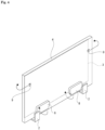
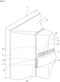
Fig. 1 illustrates, together withFigs. 2 through 12 , a display device according to the present technique, and is a perspective view illustrating a front side of the display device. - [
Fig. 2 ]
Fig. 2 is a perspective view illustrating a rear side of the display device. - [
Fig. 3 ]
Fig. 3 is a rear view of the display device shown with a rear cover removed. - [
Fig. 4 ]
Fig. 4 is a conceptual diagram illustrating directions in which output audio travels. - [
Fig. 5 ]
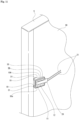
Fig. 5 is a perspective view illustrating a second speaker attached to a back chassis. - [
Fig. 6 ]
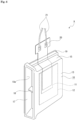
Fig. 6 is a perspective view of the second speaker. - [
Fig. 7 ]
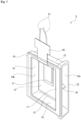
Fig. 7 is a perspective view of the second speaker, seen from a different direction fromFig. 6 . - [
Fig. 8 ]
Fig. 8 is a rear view illustrating the disposition locations of second speakers. - [
Fig. 9 ]
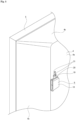
Fig. 9 is a perspective view illustrating part of the display device. - [
Fig. 10 ]
Fig. 10 is a rear view illustrating another example of the disposition of the second speakers. - [
Fig. 11 ]
Fig. 11 is a perspective view illustrating the second speaker and the like, according to an example not falling within the scope of the appended claims. - [
Fig. 12 ]
Fig. 12 is a cross-sectional view illustrating another second speaker attached to the back chassis, according to an example not falling within the scope of the appended claims. - An embodiment for carrying out a display device according to the present technique will be described with reference to the accompanying drawings.
- The following embodiment describes the display device according to the present technique being applied in a television receiver that displays images in a display.
- Note that the scope of application of the present technique is not limited to television receivers, and can be widely applied to various types of display devices, such as monitors used in personal computers and the like.
- In the following descriptions, the directions of front, rear, up, down, left, and right are described assuming the direction in which a display surface of the display device (television receiver) is facing is forward (the front side).
- A display device (television receiver) 1 is, for example, formed in a substantially rectangular shape that is long sideways and thin in a front-rear direction (see
Fig. 1 ), and is installed on an installation surface such as a floor surface using astand 2, or is attached to a wall surface using a bracket or the like (not shown). - The display device 1 includes: a
display 3 in which images are displayed; aback chassis 4 disposed behind thedisplay 3; anouter frame 5, called a bezel, disposed in the outer periphery of thedisplay 3 andback chassis 4; and arear cover 6 that covers theback chassis 4 and the like from the rear (seeFigs. 1 to 3 ). - The
display 3 is formed in the form of a plate facing in the front-rear direction, and a liquid crystal display is used as thedisplay 3, for example. Thedisplay 3 has an optical sheet such as a substrate or a polarizing film. A front surface of thedisplay 3 serves as adisplay surface 3a where images are displayed. - The
back chassis 4 is formed from a metal material, a resin material, or the like, for example, with an outer shape that is slightly larger than the display 3 (see -
Fig. 3 ). Aside from an outer peripheral part, theback chassis 4 is provided as abase surface part 4a facing in the front-rear direction, and the outer peripheral part has atop part 4b andside parts top part 4b is continuous with an upper end of thebase surface part 4a, and is inclined so as to displace forward as thetop part 4b progresses upward. Theside parts base surface part 4a, and are inclined so as to displace forward as theside parts - An element mounting substrate (not shown) is attached to a front surface of the
base surface part 4a in theback chassis 4, and a plurality of light-emitting elements, such as light-emitting diodes, which function as a backlight, are mounted on the element mounting substrate in a matrix. A diffuser plate (not shown) that diffuses light emitted from the light-emitting elements is disposed between the element mounting substrate and thedisplay 3. -
Various control boards base surface part 4a of theback chassis 4. Thecontrol boards 7 include, for example, a power supply board that controls the supply of power for the display device 1 as a whole, a backlight board that controls the turning on and off of the light-emitting elements, a signal processing board that controls images, audio, and the like, a control board that controls the display of thedisplay 3, and the like. -
First speakers base surface part 4a of theback chassis 4, so as to be separated in the horizontal direction. Note that the number of thefirst speakers 8 may be set as desired, and may be one, or three or more. Thefirst speakers 8 are, for example, dynamic speakers, and are attached to the lower edge part of thebase surface part 4a. Thefirst speakers 8 are, for example, speakers having an output band in the mid range to the low range, and audio from thefirst speakers 8 is output downward, for example. - The
first speakers first speakers display 3 to the front side (seeFig. 4 ). -
Second speakers base surface part 4a of theback chassis 4, so as to be separated in the horizontal direction (seeFigs. 3 and5 ). Note that the number of thesecond speakers 9 may be set as desired, and may be one, or three or more. - As described above, two each of the
first speakers 8 and thesecond speakers 9 are provided, with right-channel audio being output from one each of thefirst speakers 8 and thesecond speakers 9 and left-channel audio being output from the other each of thefirst speakers 8 and thesecond speakers 9, so that the audio is output in a stereo mode using right-side audio and left-side audio. - However, in the display device 1, audio may be output from the
first speakers 8 and thesecond speakers 9 in mono mode. - The
second speakers 9 are piezoelectric element speakers (piezo speakers), each including acase body 10 formed from a resin material, apiezoelectric element 11 that operates when a voltage is applied thereto, and adiaphragm 12 that vibrates in response to the operations of the piezoelectric element 11 (seeFigs. 5 to 7 ). - The
case body 10 is formed having a flat shape that is thin in the front-rear direction, and is constituted by arear surface part 13, aside surface part 14, atop surface part 15, abottom surface part 16, aconnection part 17, and areinforcement part 18, which are formed in an integral manner. - The
rear surface part 13 is formed as a flat plate that faces in the front-rear direction and is larger than theside surface part 14, thetop surface part 15, and thebottom surface part 16. Theside surface part 14 is continuous with one side edge of therear surface part 13, and is formed having a substantially rectangular shape longer in the vertical direction. Thetop surface part 15 and thebottom surface part 16 are continuous with a top edge and a bottom edge of therear surface part 13, respectively, and are formed having substantially rectangular shapes longer in the horizontal direction, with one side edge of thetop surface part 15 and one side edge of thebottom surface part 16 being continuous with top and bottom edges, respectively, of theside surface part 14. - The
connection part 17 connects another end of thetop surface part 15 in the left-right direction with another end of thebottom surface part 16 in the left-right direction, and is located in front of therear surface part 13. As such, an opening surrounded by therear surface part 13, thetop surface part 15, thebottom surface part 16, and theconnection part 17 is formed in thecase body 10, and that opening serves as anaudio passage hole 10a. Theaudio passage hole 10a is located on the opposite side from theside surface part 14 with respect to the left-right direction. - The
reinforcement part 18 is provided in a central part of theaudio passage hole 10a with respect to the up-down direction, and connects therear surface part 13 to theconnection part 17. Thereinforcement part 18 prevents deformation in which therear surface part 13 and theconnection part 17 move away from each other. - A frame-shaped
cushion 19 is affixed to the front surface of thecase body 10. The interior space of thecase body 10 is formed as adisposition space 10b, and theaudio passage hole 10a communicates with thedisposition space 10b. - In the
case body 10, thetop surface part 15 and thebottom surface part 16 are slightly inclined in such a manner that the distance therebetween in the left-right direction increases with distance from theside surface part 14. Accordingly, the distance between thetop surface part 15 and thebottom surface part 16 is smallest at the end on theside surface part 14 side and greatest at the end on theaudio passage hole 10a side. - The
piezoelectric element 11 is, for example, formed in the shape of a plate having a thickness direction that corresponds to the front-rear direction. Awiring board 20 is connected to thepiezoelectric element 11, andcables 21 are connected to thewiring board 20. Accordingly, a voltage is applied to thepiezoelectric element 11 through thecables 21 and thewiring board 20. Thewiring board 20 is, for example, a flexible printed wiring board, and is positioned and fixed over the inside and outside of thecase body 10 while inserted between thecushion 19 and thecase body 10. - The
diaphragm 12 is, for example, a metal plate having a thickness direction that corresponds to the front-rear direction, and is bonded to an inner surface of therear surface part 13. Thediaphragm 12 is slightly larger than thepiezoelectric element 11, and thepiezoelectric element 11 is affixed to a front surface of thediaphragm 12. - As such, when a voltage is applied to the
piezoelectric element 11 through thecables 21 and thewiring board 20 and thepiezoelectric element 11 deforms, thediaphragm 12 deforms and vibrates according to the deformation of thepiezoelectric element 11. The vibration of thediaphragm 12 is transmitted to thecase body 10 as well, and thecase body 10 vibrates according to the vibration of thediaphragm 12. - With the
second speakers 9, thecase body 10 is attached to thebase surface part 4a of theback chassis 4 over thecushion 19, and because thecase body 10 is attached to thebase surface part 4a over thecushion 19, thecase body 10 is capable of vibrating relative to theback chassis 4. - The
second speakers back chassis 4, for example, on the left and right ends of thebase surface part 4a, with theaudio passage holes side surface part 14 in the left-right direction, and on the upper half of theback chassis 4 in the up-down direction, above thefirst speakers second speakers Fig. 8 ). - The
second speakers 9 are, for example, speakers having an output band that is in the high to mid range, or the high range, and audio is emitted to the sides through theaudio passage holes 10a. The audio output from thesecond speakers display 3 to the front side (seeFig. 4 ). Additionally, in thesecond speakers 9, thecase body 10 vibrates in addition to thediaphragm 12, and thus the audio is output from the periphery of thecase body 10 as well. - The
outer frame 5 is, for example, constituted by four parts located at the top, bottom, left and right, joined together, and is attached to an outer peripheral part of theback chassis 4 from the outer side (seeFigs. 2 and9 ). - The
rear cover 6 is slightly smaller than theback chassis 4, and a part thereof aside from a lower edge part is provided as a main body part 22 (seeFig. 2 ). Therear cover 6 has a protrudingpart 23 projecting downward from a central part, in the left-right direction, of themain body part 22, and left and right sides of the protrudingpart 23 are formed as placement cutouts 6a and 6a. - A
band part 24 extending to the left and right is provided on a part of themain body part 22 near the upper end thereof, and theband part 24 is formed in a shape that is open both to the front and to the left and right (seeFig. 9 ). The left and right openings of theband part 24 are formed asemission holes main body part 22 includes adecorative part 25 continuous with an upper end of theband part 24, and thedecorative part 25 is constituted by a plurality of projections and recesses arranged so as to alternate in the left-right direction. - At both the left and right ends of the
main body part 22,small holes band part 24 and thedecorative part 25. Thesmall holes main body part 22 so that there is a gap between the recesses of thedecorative part 25 and theband part 24, and are connected to a space inside theband part 24. - Like the
side parts back chassis 4, the left and right end parts of themain body part 22 are inclined so as to displace forward as the end parts progress outward. - The
rear cover 6 is attached to theback chassis 4 so as to cover thebase surface part 4a from behind (seeFig. 2 ). With therear cover 6 attached to theback chassis 4, thecontrol boards main body part 22 or the protrudingpart 23, thefirst speakers second speakers band part 24, respectively. - With the
rear cover 6 attached to theback chassis 4, covers 26 and 26, which cover the placement cutouts 6a and 6a, respectively, are attached to therear cover 6 from behind, and thecovers first speakers cover 26 has a rear-side cover part 26a facing in the front-rear direction and a lower-side cover part 26b protruding forward from a lower edge part of the rear-side cover part 26a, and a mesh-shaped emission part is formed in the lower-side cover part 26b. - Accordingly, audio in the mid range to the low range, output from the
first speaker 8, is emitted downward from the emission part of the lower-side cover part 26b, and progresses around the bottom of thedisplay 3 to the front side. - On the other hand, audio in the high to mid range, or the high range, output from the
second speakers 9 is mainly emitted from theaudio passage hole 10a of thecase body 10 to the side through theemission holes 24a in theband part 24, and progresses around the sides of thedisplay 3 to the front side. Some of the audio output from thesecond speakers 9 is released upward from thecase body 10 through thesmall holes main body part 22, and progresses around the top of thedisplay 3 to the front side. - As described above, the display device 1 includes the
first speakers 8, which are disposed between thedisplay 3 and therear cover 6, and thesecond speakers 9, which are disposed between thedisplay 3 and therear cover 6 and are positioned higher than thefirst speakers 8; and each of thesecond speakers 9 outputs audio according to operations of thepiezoelectric element 11, and has a higher audio output band than thefirst speakers 8. - As such, audio in a higher range than the range of the audio output from the
first speakers 8 comes from above thefirst speakers 8 and progresses around thedisplay 3 to the front side, while audio in a lower range than the range of the audio output from thesecond speakers 9 comes from below thesecond speakers 9 and progresses around thedisplay 3 to the front side. - This enables a user to feel as if the audio is being output from the display being viewed, which enhances the sound image localization effect and ensures a good viewing state in which an image or video and audio have a sense of unity.
- In particular, it is easier for the user to feel as if the audio output from the
first speakers 8 around thedisplay 3 and the audio output from thesecond speakers 9 around thedisplay 3 are both coming from the center of thedisplay 3 being viewed, which makes it possible to ensure a realistic viewing state in which the image or video and audio have a sense of unity. - Additionally, when the height of the display device 1 as a whole is represented by L and the bottom end by 0, the
second speakers 9 are positioned between 0.7L and 0.85L. - As such, the
second speakers 9, which output audio in a higher range than thefirst speakers 8, are positioned within a predetermined range near the upper end, and thus the audio output from thesecond speakers 9 can easily move around thedisplay 3 from the left-right direction and progress toward the front side, which makes it possible to ensure a high sound image localization effect. - Furthermore, two of the
second speakers second speakers - Therefore, the audio path can be set so that the audio output from the two
second speakers display 3, respectively, to the front side, which provides a sense of a broad sound image and good sound image localization, and makes it possible to ensure a realistic viewing state for the user. - In particular, by attaching the two
second speakers back chassis 4, the audio output from thesecond speakers display 3 from the left and right sides thereof, which makes it possible to obtain an even better sense of a broad sound image and better sound image localization. - Additionally, each of the
second speakers 9 includes thecase body 10, thepiezoelectric element 11, and thediaphragm 12, and theaudio passage hole 10a, which communicates with thedisposition space 10b and through which output audio passes, is formed in thecase body 10. - Accordingly, because the audio output by the vibration of the
diaphragm 12 due to voltage being applied to thepiezoelectric element 11 passes through theaudio passage hole 10a to the outside, the audio can be guided in a desired direction according to the position in which theaudio passage hole 10a is formed in thecase body 10, which makes it possible to enhance the sound image localization and ensure a good viewing state. - Furthermore, because the
case body 10 is formed having a shape in which the width increases as thecase body 10 progresses toward theaudio passage hole 10a, the output audio progresses along thetop surface part 15 andbottom surface part 16, which are both side surface parts in the width direction, toward theaudio passage hole 10a, and the size of theaudio passage hole 10a increases in the width direction, which makes it possible to smoothly emit audio at a high sound pressure from theaudio passage hole 10a. - Although the foregoing describes an example in which the
second speakers back chassis 4, thesecond speakers second speakers first speakers 8. - The
second speakers Fig. 10 ). By disposing the twosecond speakers back chassis 4, the audio output from thesecond speakers display 3 from the left and right sides thereof, which makes it possible to obtain a sense of a broad sound image and good sound image localization. - Additionally, although the foregoing describes the
second speakers 9, each including thecase body 10 having theinterior space 10b, as an example not falling within the scope of the appended claims, it is also possible to usesecond speakers 9A, in which the configuration of the case body is different, instead of the second speakers 9 (seeFigs. 11 and12 ). - Each of the
second speakers 9A includes acase body 10A formed from a resin material, thepiezoelectric element 11 that operates when a voltage is applied thereto, and thediaphragm 12 that vibrates in response to the operations of thepiezoelectric element 11. - The
case body 10A includes anattachment part 30 to which thediaphragm 12 is attached, andleg parts attachment part 30. Theattachment part 30 is formed as a plate having a substantially rectangular shape, and has ashallow recess part 30a open on one side in the thickness direction. Theleg parts attachment part 30, and are separated from each other in the up-down direction. Theattachment part 30 is inclined relative to the direction in which theleg parts 31 protrude.Cushions leg parts - The
diaphragm 12 is bonded to theattachment part 30 with thediaphragm 12 disposed in therecess part 30a. - In the example in which the
second speakers 9A are used, for example, aback chassis 4A is used, and theentire back chassis 4A is formed as a substantially flat plate. Additionally, in the example in which thesecond speakers 9A are used, for example, arear cover 6A is used, therear cover 6A being formed at substantially the same size as theback chassis 4A, and having left and right end parts that are inclined so as to move closer to theback chassis 4A as the left and right end parts approach both ends in the left-right direction. - In each of the
second speakers 9A, theleg parts case body 10A are attached to end parts, in the left-right direction, of theback chassis 4A, over thecushions case body 10A is attached to theback chassis 4A over thecushions case body 10A to vibrate relative to theback chassis 4A. Alternatively, thecase body 10A can be attached with screws. - In each of the
second speakers 9A, theattachment part 30 of thecase body 10A is inclined, and theattachment part 30 is positioned so as to follow the inclined state of therear cover 6A while being attached to theback chassis 4A. Accordingly, thepiezoelectric element 11 and thediaphragm 12, which are attached to theattachment part 30, are positioned opposite each other while substantially parallel to the inner surface of therear cover 6A. - The audio output from the
second speakers 9A is emitted to the sides through theemission holes 24a, and progresses around the sides of thedisplay 3 to the front side. - Note that in the example where the
second speakers 9A are used, emission holes that penetrate in the front-rear direction may be formed in therear cover 6A at positions opposite thepiezoelectric element 11 and thediaphragm 12, and when such emission holes are formed, the audio output from thesecond speakers 9A is emitted to the rear through the emission holes, and progresses around the sides and above thedisplay 3 to the front side. - Additionally, the
small holes rear cover 6A, and when thesmall holes second speakers 9A is emitted upward through thesmall holes display 3 to the front side. - When the
second speakers 9A are used as described above, thecase body 10A is formed substantially in a plate shape, and thesecond speakers 9A can be disposed in a small space by varying the lengths of theleg parts attachment part 30 in the protrusion direction in accordance with the space for disposition. This makes it possible to miniaturize thesecond speakers 9A, and effectively utilizing the space makes it possible to increase the freedom of design. - Additionally, because the
second speakers 9A and 9a can be disposed at the left and right ends, the audio output from thesecond speakers display 3 from the left and right sides thereof, which makes it possible to obtain a sense of a broad sound image and good sound image localization. -
- 1
- Display device
- 3
- Display
- 3A
- Display surface
- 6
- Rear cover
- 8
- First speaker
- 9
- Second speaker
- 10
- Case body
- 10a
- Audio passage hole
- 10b
- Disposition space
- 11
- Piezoelectric element
- 12
- Diaphragm
- 9A
- Second speaker
- 10A
- Case body
Claims (4)
- A display device (1) comprising:a display (3) configured to display an image on a display surface (3a);a rear cover (6) disposed on a rear side of the display (3);one or more first speaker (8) disposed between the display (3) and the rear cover (6); andone or more second speaker (9) disposed between the display (3) and the rear cover (6) and positioned higher than the one or more first speaker (8), whereinthe one or more second speaker (9) has a higher audio output band than the one or more first speaker (8),characterized in thatthe one or more second speaker (9) each comprises:a case body (10) constituted by a rear surface part (13), a side surface part (14), a top surface part (15), a bottom surface part (16), a connection part (17) and a reinforcement part (18), the side surface part (14) being continuous with one side edge of the rear surface part (13), the top surface part (15) and the bottom surface part (16) respectively being continuous with a top edge and a bottom edge of the rear surface part (13), one side edge of the top surface part (15) and one side edge of the bottom surface part (16) being continuous with top and bottom edges, respectively, of the side surface part (14), the connection part (17) connecting another end of the top surface part (15) with another end of the bottom surface part (16), and being located in front of the rear surface part (13);a diaphragm (12) being bonded to an inner surface of the rear surface part (13);a piezoelectric element (11) affixed to a front surface of the diaphragm (12) and configured to operate by application of a voltage, wherein the diaphragm (12) is configured to vibrate according to operation of the piezoelectric element (11); andan audio passage hole (12a) formed in the case body (10), wherein the audio passage hole (12a) is surrounded by the rear surface part (13), the top surface part (15), the bottom surface part (16) and the connection part (17), wherein the audio passage hole (10a) is located opposite to the side surface part (14), whereinthe reinforcement part (18) is provided in a central part of the audio passage hole (10a) and connects the rear surface part (13) to the connection part (17), and wherein output audio passes through the audio passage hole (12a).
- The display device (1) according to claim 1, wherein,when an overall height of the display device (1) is represented by L and a bottom end is represented by 0,the second speaker is positioned between 0.7L and 0.85L.
- The display device (1) according to claim 1 or claim 2, whereintwo second speakers are provided, andthe two second speakers are positioned horizontally-separated from each other.
- The display device (1) according to any one of claims 1 to 3, wherein
the case body (10) is formed having a shape in which a width increases as the case body (10) progresses toward the audio passage hole (12a).
Applications Claiming Priority (2)
| Application Number | Priority Date | Filing Date | Title |
|---|---|---|---|
| MYPI2018003052A MY203968A (en) | 2018-12-31 | 2018-12-31 | Display device and speaker |
| PCT/JP2019/045617 WO2020141581A1 (en) | 2018-12-31 | 2019-11-21 | Display device and speaker |
Publications (3)
| Publication Number | Publication Date |
|---|---|
| EP3908008A1 EP3908008A1 (en) | 2021-11-10 |
| EP3908008A4 EP3908008A4 (en) | 2022-07-20 |
| EP3908008B1 true EP3908008B1 (en) | 2024-11-06 |
Family
ID=71407317
Family Applications (1)
| Application Number | Title | Priority Date | Filing Date |
|---|---|---|---|
| EP19906901.4A Active EP3908008B1 (en) | 2018-12-31 | 2019-11-21 | Display device and speaker |
Country Status (7)
| Country | Link |
|---|---|
| US (1) | US11962972B2 (en) |
| EP (1) | EP3908008B1 (en) |
| JP (1) | JP7577998B2 (en) |
| KR (1) | KR102663477B1 (en) |
| CN (1) | CN113170244A (en) |
| MY (1) | MY203968A (en) |
| WO (1) | WO2020141581A1 (en) |
Families Citing this family (4)
| Publication number | Priority date | Publication date | Assignee | Title |
|---|---|---|---|---|
| CN114173228A (en) * | 2021-09-07 | 2022-03-11 | 山东华菱电子股份有限公司 | Loudspeaker system and use thereof |
| US20250211706A1 (en) * | 2022-03-23 | 2025-06-26 | Lg Electronics Inc. | Display device |
| JP2025071391A (en) * | 2022-03-25 | 2025-05-08 | ソニーグループ株式会社 | Display device |
| JPWO2023182067A1 (en) * | 2022-03-25 | 2023-09-28 |
Family Cites Families (26)
| Publication number | Priority date | Publication date | Assignee | Title |
|---|---|---|---|---|
| JPH04133295U (en) * | 1991-06-03 | 1992-12-11 | 日興電機工業株式会社 | sound device |
| JPH0662489A (en) | 1992-08-05 | 1994-03-04 | Mitsubishi Electric Corp | Multichannel audio reproducing device |
| JP3514857B2 (en) * | 1995-02-06 | 2004-03-31 | 株式会社東芝 | TV set speaker system |
| US5796854A (en) * | 1997-03-04 | 1998-08-18 | Compaq Computer Corp. | Thin film speaker apparatus for use in a thin film video monitor device |
| US5942734A (en) * | 1998-08-06 | 1999-08-24 | Dresser Industries, Inc. | Noise-attenuating shielding unit and method for loudspeakers |
| JP2000102082A (en) | 1998-09-28 | 2000-04-07 | Murata Mfg Co Ltd | Amplifier with built-in speaker |
| US6430297B1 (en) | 1998-09-28 | 2002-08-06 | Murata Manufacturing Co., Ltd. | Speaker and speaker device |
| JP2002359890A (en) | 2001-03-30 | 2002-12-13 | Taiyo Yuden Co Ltd | Display device and electronic equipment |
| KR100540981B1 (en) | 2003-03-07 | 2006-01-11 | 송종석 | Horn Speaker |
| JP2005123757A (en) | 2003-10-15 | 2005-05-12 | Citizen Watch Co Ltd | Piezoelectric acoustic device |
| JP5010810B2 (en) | 2005-05-13 | 2012-08-29 | 三洋電機株式会社 | Electronics |
| KR101196953B1 (en) * | 2005-10-06 | 2012-11-05 | 삼성전자주식회사 | Speaker device for portable terminal |
| JP4900066B2 (en) * | 2007-06-12 | 2012-03-21 | ミツミ電機株式会社 | Manufacturing method of ultrasonic sensor |
| KR100929020B1 (en) * | 2008-01-17 | 2009-11-26 | 성균관대학교산학협력단 | Sound output system of wall-mounted flat panel display |
| WO2012153537A1 (en) | 2011-05-11 | 2012-11-15 | パナソニック株式会社 | Video display device |
| CN202949552U (en) * | 2012-11-15 | 2013-05-22 | 瑞声光电科技(常州)有限公司 | Acoustic generator |
| CN103269462B (en) * | 2013-05-10 | 2016-09-28 | 歌尔声学股份有限公司 | Speaker module |
| CN105191349B (en) * | 2013-05-15 | 2019-01-08 | 索尼公司 | Sound output device, method of outputting acoustic sound and image display device |
| EP2890228A1 (en) * | 2013-12-24 | 2015-07-01 | Samsung Electronics Co., Ltd | Radiation apparatus |
| JP2015186197A (en) * | 2014-03-26 | 2015-10-22 | パナソニックIpマネジメント株式会社 | display device |
| CN203840490U (en) * | 2014-04-29 | 2014-09-17 | 歌尔声学股份有限公司 | Loudspeaker module group of side sound-outlet structure |
| KR101704517B1 (en) * | 2016-03-28 | 2017-02-09 | 엘지디스플레이 주식회사 | Display device for generating sound by panel vibration type |
| JP2018007220A (en) | 2016-07-09 | 2018-01-11 | オーツェイド株式会社 | Tweeter unit and earphone |
| JP6443710B2 (en) | 2016-09-28 | 2018-12-26 | 株式会社村田製作所 | Piezoelectric sounding parts |
| WO2018088774A1 (en) | 2016-11-08 | 2018-05-17 | Lg Electronics Inc. | Display apparatus |
| KR102560990B1 (en) | 2016-12-09 | 2023-08-01 | 삼성전자주식회사 | Directional speaker and display apparatus having the same |
-
2018
- 2018-12-31 MY MYPI2018003052A patent/MY203968A/en unknown
-
2019
- 2019-11-21 JP JP2020563861A patent/JP7577998B2/en active Active
- 2019-11-21 KR KR1020217017951A patent/KR102663477B1/en active Active
- 2019-11-21 WO PCT/JP2019/045617 patent/WO2020141581A1/en not_active Ceased
- 2019-11-21 US US17/309,811 patent/US11962972B2/en active Active
- 2019-11-21 EP EP19906901.4A patent/EP3908008B1/en active Active
- 2019-11-21 CN CN201980077291.5A patent/CN113170244A/en active Pending
Also Published As
| Publication number | Publication date |
|---|---|
| JPWO2020141581A1 (en) | 2021-11-25 |
| EP3908008A4 (en) | 2022-07-20 |
| WO2020141581A1 (en) | 2020-07-09 |
| US20220078560A1 (en) | 2022-03-10 |
| CN113170244A (en) | 2021-07-23 |
| MY203968A (en) | 2024-07-26 |
| US11962972B2 (en) | 2024-04-16 |
| KR20210110802A (en) | 2021-09-09 |
| EP3908008A1 (en) | 2021-11-10 |
| JP7577998B2 (en) | 2024-11-06 |
| KR102663477B1 (en) | 2024-05-09 |
Similar Documents
| Publication | Publication Date | Title |
|---|---|---|
| US11962972B2 (en) | Display device and speaker | |
| CN112188365B (en) | Display device | |
| US9942640B2 (en) | Sound output apparatus, sound output method and image display apparatus | |
| JP2010256607A (en) | Image display | |
| US11765491B2 (en) | Display device and speaker unit | |
| KR20240007309A (en) | Display apparatus | |
| JP2014206644A (en) | Display device | |
| EP3905711B1 (en) | Display device | |
| JP2019003212A (en) | Display device | |
| KR20250103081A (en) | Display apparatus | |
| WO2022186307A1 (en) | Electronic musical instrument | |
| JP2007216861A (en) | Fixing structure for drive means and vehicular information provision device | |
| JP2007238069A (en) | Vehicular information provision device |
Legal Events
| Date | Code | Title | Description |
|---|---|---|---|
| STAA | Information on the status of an ep patent application or granted ep patent |
Free format text: STATUS: THE INTERNATIONAL PUBLICATION HAS BEEN MADE |
|
| PUAI | Public reference made under article 153(3) epc to a published international application that has entered the european phase |
Free format text: ORIGINAL CODE: 0009012 |
|
| STAA | Information on the status of an ep patent application or granted ep patent |
Free format text: STATUS: REQUEST FOR EXAMINATION WAS MADE |
|
| 17P | Request for examination filed |
Effective date: 20210802 |
|
| AK | Designated contracting states |
Kind code of ref document: A1 Designated state(s): AL AT BE BG CH CY CZ DE DK EE ES FI FR GB GR HR HU IE IS IT LI LT LU LV MC MK MT NL NO PL PT RO RS SE SI SK SM TR |
|
| RIC1 | Information provided on ipc code assigned before grant |
Ipc: H04R 17/00 20060101ALN20220118BHEP Ipc: H04N 5/64 20060101ALN20220118BHEP Ipc: H04R 1/34 20060101ALN20220118BHEP Ipc: H04R 1/26 20060101AFI20220118BHEP |
|
| DAV | Request for validation of the european patent (deleted) | ||
| DAX | Request for extension of the european patent (deleted) | ||
| A4 | Supplementary search report drawn up and despatched |
Effective date: 20220622 |
|
| RIC1 | Information provided on ipc code assigned before grant |
Ipc: H04R 17/00 20060101ALN20220616BHEP Ipc: H04N 5/64 20060101ALN20220616BHEP Ipc: H04R 1/34 20060101ALN20220616BHEP Ipc: H04R 1/26 20060101AFI20220616BHEP |
|
| REG | Reference to a national code |
Ref country code: DE Ref legal event code: R079 Free format text: PREVIOUS MAIN CLASS: H04R0001020000 Ipc: H04R0001260000 Ref document number: 602019061739 Country of ref document: DE |
|
| GRAP | Despatch of communication of intention to grant a patent |
Free format text: ORIGINAL CODE: EPIDOSNIGR1 |
|
| STAA | Information on the status of an ep patent application or granted ep patent |
Free format text: STATUS: GRANT OF PATENT IS INTENDED |
|
| RIC1 | Information provided on ipc code assigned before grant |
Ipc: H04R 17/00 20060101ALN20240514BHEP Ipc: H04N 5/64 20060101ALN20240514BHEP Ipc: H04R 1/34 20060101ALN20240514BHEP Ipc: G06F 1/16 20060101ALI20240514BHEP Ipc: H04R 1/26 20060101AFI20240514BHEP |
|
| INTG | Intention to grant announced |
Effective date: 20240607 |
|
| GRAS | Grant fee paid |
Free format text: ORIGINAL CODE: EPIDOSNIGR3 |
|
| GRAA | (expected) grant |
Free format text: ORIGINAL CODE: 0009210 |
|
| STAA | Information on the status of an ep patent application or granted ep patent |
Free format text: STATUS: THE PATENT HAS BEEN GRANTED |
|
| P01 | Opt-out of the competence of the unified patent court (upc) registered |
Free format text: CASE NUMBER: APP_52304/2024 Effective date: 20240918 |
|
| AK | Designated contracting states |
Kind code of ref document: B1 Designated state(s): AL AT BE BG CH CY CZ DE DK EE ES FI FR GB GR HR HU IE IS IT LI LT LU LV MC MK MT NL NO PL PT RO RS SE SI SK SM TR |
|
| REG | Reference to a national code |
Ref country code: GB Ref legal event code: FG4D |
|
| REG | Reference to a national code |
Ref country code: CH Ref legal event code: EP |
|
| REG | Reference to a national code |
Ref country code: DE Ref legal event code: R096 Ref document number: 602019061739 Country of ref document: DE |
|
| REG | Reference to a national code |
Ref country code: IE Ref legal event code: FG4D |
|
| REG | Reference to a national code |
Ref country code: LT Ref legal event code: MG9D |
|
| REG | Reference to a national code |
Ref country code: NL Ref legal event code: MP Effective date: 20241106 |
|
| PG25 | Lapsed in a contracting state [announced via postgrant information from national office to epo] |
Ref country code: HR Free format text: LAPSE BECAUSE OF FAILURE TO SUBMIT A TRANSLATION OF THE DESCRIPTION OR TO PAY THE FEE WITHIN THE PRESCRIBED TIME-LIMIT Effective date: 20241106 Ref country code: IS Free format text: LAPSE BECAUSE OF FAILURE TO SUBMIT A TRANSLATION OF THE DESCRIPTION OR TO PAY THE FEE WITHIN THE PRESCRIBED TIME-LIMIT Effective date: 20250306 Ref country code: PT Free format text: LAPSE BECAUSE OF FAILURE TO SUBMIT A TRANSLATION OF THE DESCRIPTION OR TO PAY THE FEE WITHIN THE PRESCRIBED TIME-LIMIT Effective date: 20250306 |
|
| PG25 | Lapsed in a contracting state [announced via postgrant information from national office to epo] |
Ref country code: NL Free format text: LAPSE BECAUSE OF FAILURE TO SUBMIT A TRANSLATION OF THE DESCRIPTION OR TO PAY THE FEE WITHIN THE PRESCRIBED TIME-LIMIT Effective date: 20241106 Ref country code: FI Free format text: LAPSE BECAUSE OF FAILURE TO SUBMIT A TRANSLATION OF THE DESCRIPTION OR TO PAY THE FEE WITHIN THE PRESCRIBED TIME-LIMIT Effective date: 20241106 |
|
| REG | Reference to a national code |
Ref country code: AT Ref legal event code: MK05 Ref document number: 1740704 Country of ref document: AT Kind code of ref document: T Effective date: 20241106 |
|
| PG25 | Lapsed in a contracting state [announced via postgrant information from national office to epo] |
Ref country code: BG Free format text: LAPSE BECAUSE OF FAILURE TO SUBMIT A TRANSLATION OF THE DESCRIPTION OR TO PAY THE FEE WITHIN THE PRESCRIBED TIME-LIMIT Effective date: 20241106 |
|
| PG25 | Lapsed in a contracting state [announced via postgrant information from national office to epo] |
Ref country code: ES Free format text: LAPSE BECAUSE OF FAILURE TO SUBMIT A TRANSLATION OF THE DESCRIPTION OR TO PAY THE FEE WITHIN THE PRESCRIBED TIME-LIMIT Effective date: 20241106 |
|
| PG25 | Lapsed in a contracting state [announced via postgrant information from national office to epo] |
Ref country code: NO Free format text: LAPSE BECAUSE OF FAILURE TO SUBMIT A TRANSLATION OF THE DESCRIPTION OR TO PAY THE FEE WITHIN THE PRESCRIBED TIME-LIMIT Effective date: 20250206 |
|
| PG25 | Lapsed in a contracting state [announced via postgrant information from national office to epo] |
Ref country code: LV Free format text: LAPSE BECAUSE OF FAILURE TO SUBMIT A TRANSLATION OF THE DESCRIPTION OR TO PAY THE FEE WITHIN THE PRESCRIBED TIME-LIMIT Effective date: 20241106 Ref country code: GR Free format text: LAPSE BECAUSE OF FAILURE TO SUBMIT A TRANSLATION OF THE DESCRIPTION OR TO PAY THE FEE WITHIN THE PRESCRIBED TIME-LIMIT Effective date: 20250207 Ref country code: AT Free format text: LAPSE BECAUSE OF FAILURE TO SUBMIT A TRANSLATION OF THE DESCRIPTION OR TO PAY THE FEE WITHIN THE PRESCRIBED TIME-LIMIT Effective date: 20241106 |
|
| PG25 | Lapsed in a contracting state [announced via postgrant information from national office to epo] |
Ref country code: PL Free format text: LAPSE BECAUSE OF FAILURE TO SUBMIT A TRANSLATION OF THE DESCRIPTION OR TO PAY THE FEE WITHIN THE PRESCRIBED TIME-LIMIT Effective date: 20241106 |
|
| PG25 | Lapsed in a contracting state [announced via postgrant information from national office to epo] |
Ref country code: RS Free format text: LAPSE BECAUSE OF FAILURE TO SUBMIT A TRANSLATION OF THE DESCRIPTION OR TO PAY THE FEE WITHIN THE PRESCRIBED TIME-LIMIT Effective date: 20250206 |
|
| REG | Reference to a national code |
Ref country code: CH Ref legal event code: PL |
|
| PG25 | Lapsed in a contracting state [announced via postgrant information from national office to epo] |
Ref country code: SM Free format text: LAPSE BECAUSE OF FAILURE TO SUBMIT A TRANSLATION OF THE DESCRIPTION OR TO PAY THE FEE WITHIN THE PRESCRIBED TIME-LIMIT Effective date: 20241106 |
|
| PG25 | Lapsed in a contracting state [announced via postgrant information from national office to epo] |
Ref country code: DK Free format text: LAPSE BECAUSE OF FAILURE TO SUBMIT A TRANSLATION OF THE DESCRIPTION OR TO PAY THE FEE WITHIN THE PRESCRIBED TIME-LIMIT Effective date: 20241106 |
|
| PG25 | Lapsed in a contracting state [announced via postgrant information from national office to epo] |
Ref country code: LU Free format text: LAPSE BECAUSE OF NON-PAYMENT OF DUE FEES Effective date: 20241121 |
|
| REG | Reference to a national code |
Ref country code: CH Ref legal event code: PL |
|
| PG25 | Lapsed in a contracting state [announced via postgrant information from national office to epo] |
Ref country code: EE Free format text: LAPSE BECAUSE OF FAILURE TO SUBMIT A TRANSLATION OF THE DESCRIPTION OR TO PAY THE FEE WITHIN THE PRESCRIBED TIME-LIMIT Effective date: 20241106 |
|
| PG25 | Lapsed in a contracting state [announced via postgrant information from national office to epo] |
Ref country code: CH Free format text: LAPSE BECAUSE OF NON-PAYMENT OF DUE FEES Effective date: 20241130 |
|
| PG25 | Lapsed in a contracting state [announced via postgrant information from national office to epo] |
Ref country code: RO Free format text: LAPSE BECAUSE OF FAILURE TO SUBMIT A TRANSLATION OF THE DESCRIPTION OR TO PAY THE FEE WITHIN THE PRESCRIBED TIME-LIMIT Effective date: 20241106 |
|
| PG25 | Lapsed in a contracting state [announced via postgrant information from national office to epo] |
Ref country code: SK Free format text: LAPSE BECAUSE OF FAILURE TO SUBMIT A TRANSLATION OF THE DESCRIPTION OR TO PAY THE FEE WITHIN THE PRESCRIBED TIME-LIMIT Effective date: 20241106 |
|
| PG25 | Lapsed in a contracting state [announced via postgrant information from national office to epo] |
Ref country code: CZ Free format text: LAPSE BECAUSE OF FAILURE TO SUBMIT A TRANSLATION OF THE DESCRIPTION OR TO PAY THE FEE WITHIN THE PRESCRIBED TIME-LIMIT Effective date: 20241106 |
|
| PG25 | Lapsed in a contracting state [announced via postgrant information from national office to epo] |
Ref country code: IT Free format text: LAPSE BECAUSE OF FAILURE TO SUBMIT A TRANSLATION OF THE DESCRIPTION OR TO PAY THE FEE WITHIN THE PRESCRIBED TIME-LIMIT Effective date: 20241106 |
|
| REG | Reference to a national code |
Ref country code: DE Ref legal event code: R097 Ref document number: 602019061739 Country of ref document: DE |
|
| REG | Reference to a national code |
Ref country code: BE Ref legal event code: MM Effective date: 20241130 |
|
| PG25 | Lapsed in a contracting state [announced via postgrant information from national office to epo] |
Ref country code: SE Free format text: LAPSE BECAUSE OF FAILURE TO SUBMIT A TRANSLATION OF THE DESCRIPTION OR TO PAY THE FEE WITHIN THE PRESCRIBED TIME-LIMIT Effective date: 20241106 |
|
| PLBE | No opposition filed within time limit |
Free format text: ORIGINAL CODE: 0009261 |
|
| STAA | Information on the status of an ep patent application or granted ep patent |
Free format text: STATUS: NO OPPOSITION FILED WITHIN TIME LIMIT |
|
| PG25 | Lapsed in a contracting state [announced via postgrant information from national office to epo] |
Ref country code: MC Free format text: LAPSE BECAUSE OF FAILURE TO SUBMIT A TRANSLATION OF THE DESCRIPTION OR TO PAY THE FEE WITHIN THE PRESCRIBED TIME-LIMIT Effective date: 20241106 |
|
| 26N | No opposition filed |
Effective date: 20250807 |
|
| PG25 | Lapsed in a contracting state [announced via postgrant information from national office to epo] |
Ref country code: BE Free format text: LAPSE BECAUSE OF NON-PAYMENT OF DUE FEES Effective date: 20241130 |
|
| PG25 | Lapsed in a contracting state [announced via postgrant information from national office to epo] |
Ref country code: FR Free format text: LAPSE BECAUSE OF NON-PAYMENT OF DUE FEES Effective date: 20250106 |
|
| PG25 | Lapsed in a contracting state [announced via postgrant information from national office to epo] |
Ref country code: IE Free format text: LAPSE BECAUSE OF NON-PAYMENT OF DUE FEES Effective date: 20241121 |
|
| PGFP | Annual fee paid to national office [announced via postgrant information from national office to epo] |
Ref country code: DE Payment date: 20251022 Year of fee payment: 7 |
|
| PGFP | Annual fee paid to national office [announced via postgrant information from national office to epo] |
Ref country code: GB Payment date: 20251023 Year of fee payment: 7 |
|
| PG25 | Lapsed in a contracting state [announced via postgrant information from national office to epo] |
Ref country code: HU Free format text: LAPSE BECAUSE OF FAILURE TO SUBMIT A TRANSLATION OF THE DESCRIPTION OR TO PAY THE FEE WITHIN THE PRESCRIBED TIME-LIMIT; INVALID AB INITIO Effective date: 20191121 |
|
| PG25 | Lapsed in a contracting state [announced via postgrant information from national office to epo] |
Ref country code: CY Free format text: LAPSE BECAUSE OF FAILURE TO SUBMIT A TRANSLATION OF THE DESCRIPTION OR TO PAY THE FEE WITHIN THE PRESCRIBED TIME-LIMIT; INVALID AB INITIO Effective date: 20191121 |