EP3907908A1 - Derivation method, communication system and accommodation station apparatus - Google Patents
Derivation method, communication system and accommodation station apparatus Download PDFInfo
- Publication number
- EP3907908A1 EP3907908A1 EP20756641.5A EP20756641A EP3907908A1 EP 3907908 A1 EP3907908 A1 EP 3907908A1 EP 20756641 A EP20756641 A EP 20756641A EP 3907908 A1 EP3907908 A1 EP 3907908A1
- Authority
- EP
- European Patent Office
- Prior art keywords
- time
- station device
- wavelength
- optical
- optical signal
- Prior art date
- Legal status (The legal status is an assumption and is not a legal conclusion. Google has not performed a legal analysis and makes no representation as to the accuracy of the status listed.)
- Granted
Links
Images


Classifications
-
- H—ELECTRICITY
- H04—ELECTRIC COMMUNICATION TECHNIQUE
- H04B—TRANSMISSION
- H04B10/00—Transmission systems employing electromagnetic waves other than radio-waves, e.g. infrared, visible or ultraviolet light, or employing corpuscular radiation, e.g. quantum communication
- H04B10/25—Arrangements specific to fibre transmission
- H04B10/2575—Radio-over-fibre, e.g. radio frequency signal modulated onto an optical carrier
- H04B10/25752—Optical arrangements for wireless networks
- H04B10/25758—Optical arrangements for wireless networks between a central unit and a single remote unit by means of an optical fibre
- H04B10/25759—Details of the reception of RF signal or the optical conversion before the optical fibre
-
- H—ELECTRICITY
- H04—ELECTRIC COMMUNICATION TECHNIQUE
- H04B—TRANSMISSION
- H04B10/00—Transmission systems employing electromagnetic waves other than radio-waves, e.g. infrared, visible or ultraviolet light, or employing corpuscular radiation, e.g. quantum communication
- H04B10/07—Arrangements for monitoring or testing transmission systems; Arrangements for fault measurement of transmission systems
- H04B10/075—Arrangements for monitoring or testing transmission systems; Arrangements for fault measurement of transmission systems using an in-service signal
- H04B10/077—Arrangements for monitoring or testing transmission systems; Arrangements for fault measurement of transmission systems using an in-service signal using a supervisory or additional signal
-
- H—ELECTRICITY
- H04—ELECTRIC COMMUNICATION TECHNIQUE
- H04B—TRANSMISSION
- H04B10/00—Transmission systems employing electromagnetic waves other than radio-waves, e.g. infrared, visible or ultraviolet light, or employing corpuscular radiation, e.g. quantum communication
- H04B10/25—Arrangements specific to fibre transmission
- H04B10/2575—Radio-over-fibre, e.g. radio frequency signal modulated onto an optical carrier
- H04B10/25752—Optical arrangements for wireless networks
- H04B10/25753—Distribution optical network, e.g. between a base station and a plurality of remote units
- H04B10/25754—Star network topology
-
- H—ELECTRICITY
- H04—ELECTRIC COMMUNICATION TECHNIQUE
- H04B—TRANSMISSION
- H04B7/00—Radio transmission systems, i.e. using radiation field
- H04B7/02—Diversity systems; Multi-antenna system, i.e. transmission or reception using multiple antennas
- H04B7/04—Diversity systems; Multi-antenna system, i.e. transmission or reception using multiple antennas using two or more spaced independent antennas
- H04B7/06—Diversity systems; Multi-antenna system, i.e. transmission or reception using multiple antennas using two or more spaced independent antennas at the transmitting station
- H04B7/0613—Diversity systems; Multi-antenna system, i.e. transmission or reception using multiple antennas using two or more spaced independent antennas at the transmitting station using simultaneous transmission
- H04B7/0615—Diversity systems; Multi-antenna system, i.e. transmission or reception using multiple antennas using two or more spaced independent antennas at the transmitting station using simultaneous transmission of weighted versions of same signal
- H04B7/0617—Diversity systems; Multi-antenna system, i.e. transmission or reception using multiple antennas using two or more spaced independent antennas at the transmitting station using simultaneous transmission of weighted versions of same signal for beam forming
-
- H—ELECTRICITY
- H04—ELECTRIC COMMUNICATION TECHNIQUE
- H04B—TRANSMISSION
- H04B7/00—Radio transmission systems, i.e. using radiation field
- H04B7/02—Diversity systems; Multi-antenna system, i.e. transmission or reception using multiple antennas
- H04B7/04—Diversity systems; Multi-antenna system, i.e. transmission or reception using multiple antennas using two or more spaced independent antennas
- H04B7/06—Diversity systems; Multi-antenna system, i.e. transmission or reception using multiple antennas using two or more spaced independent antennas at the transmitting station
- H04B7/0613—Diversity systems; Multi-antenna system, i.e. transmission or reception using multiple antennas using two or more spaced independent antennas at the transmitting station using simultaneous transmission
- H04B7/0667—Diversity systems; Multi-antenna system, i.e. transmission or reception using multiple antennas using two or more spaced independent antennas at the transmitting station using simultaneous transmission of delayed versions of same signal
-
- H—ELECTRICITY
- H04—ELECTRIC COMMUNICATION TECHNIQUE
- H04W—WIRELESS COMMUNICATION NETWORKS
- H04W16/00—Network planning, e.g. coverage or traffic planning tools; Network deployment, e.g. resource partitioning or cells structures
- H04W16/24—Cell structures
- H04W16/26—Cell enhancers or enhancement, e.g. for tunnels, building shadow
-
- H—ELECTRICITY
- H04—ELECTRIC COMMUNICATION TECHNIQUE
- H04W—WIRELESS COMMUNICATION NETWORKS
- H04W88/00—Devices specially adapted for wireless communication networks, e.g. terminals, base stations or access point devices
- H04W88/08—Access point devices
- H04W88/085—Access point devices with remote components
-
- H—ELECTRICITY
- H04—ELECTRIC COMMUNICATION TECHNIQUE
- H04W—WIRELESS COMMUNICATION NETWORKS
- H04W92/00—Interfaces specially adapted for wireless communication networks
- H04W92/04—Interfaces between hierarchically different network devices
- H04W92/12—Interfaces between hierarchically different network devices between access points and access point controllers
Definitions
- the present invention relates to a derivation method, a communication system, and an accommodation station device.
- millimeter-wave band communication which can use broader bandwidths than microwave bands, in order to meet the growing demand for wireless communication.
- propagation loss increases according to radio signal frequencies in a wireless segment, a transmission distance of millimeter-wave band communication is shorter than a transmission distance of microwave band communication. Accordingly, a communication system for millimeter-wave band communication is capable of communication in a more limited area.
- a method is proposed that expands an area by placing an antenna in such a manner that the antenna extends outward from a signal processing unit.
- an accommodation station device including the signal processing unit is separated from the antenna by using a radio-over-fiber (RoF) technology.
- the antenna is placed as an extension station device, whereby an apparent coverage area is expanded.
- the coverage area is further expanded through point to multi point (P2MP), in which a plurality of antennas are connected to a single signal processing unit. Separation of the signal processing unit from the antennas is expected to bring about configurational simplification and power saving of the extension station devices, and cost merits.
- P2MP point to multi point
- a method for connecting the plurality of antennas to the single signal processing unit a method using a passive optical network (PON) technology is considered.
- PON passive optical network
- BF beamforming
- Radio waves are concentratedly radiated in a specified direction through beamforming, whereby power lost as propagation loss is compensated for.
- a communication system needs to control directivity of radio waves (directivity control) by using a plurality of antenna elements.
- a typical method for the optical beamforming is a method in which a signal processing unit forms a beam, according to a phase delay that occurs differently per wavelength due to wavelength dispersion in an optical fiber (see Patent Document 1, Non-Patent Document 1).
- the accommodation station device derives phase delays occurring in an optical fiber.
- the signal processing unit needs to estimate a length of the optical fiber (hereinafter, referred to as "optical fiber length").
- Methods for estimating an optical fiber length include a method in which Optical Time Domain Reflectometry (OTDR) is used (see Non-Patent Document 2), and a method in which Round Trip Time (RTT) is used (see Non-Patent Document 3).
- OTDR Optical Time Domain Reflectometry
- RTT Round Trip Time
- Patent Document 1 Japanese Patent No. 4246724
- an accommodation station device estimates an optical fiber length, based on a time period from when a pulse signal is transmitted to an extension station device until the pulse signal reflected by the extension station device returns to the accommodation station device.
- an optical fiber forms a passive optical network (PON)
- PON passive optical network
- the accommodation station device cannot identify which extension station device the pulse signal is reflected from, because a plurality of pulse signals reflected from a plurality of extension station devices are mixed up. Accordingly, the accommodation station device cannot estimate an optical fiber length.
- an accommodation station device measures a time period taken by a signal to make a round trip (round trip time) between the accommodation station device and an extension station device, through a sequence called P2MP discovery.
- the accommodation station device estimates an optical fiber length, based on the measured round trip time.
- the extension station device transmits, to the accommodation station device, a frame in which an own identifier of the extension station device is embedded.
- the accommodation station device measures a round trip time between the accommodation station device and each extension station device, based on an identifier embedded in a frame received from the extension station device.
- each extension station device since an extension station device needs to embed an own identifier of the extension station device into a frame, each extension station device needs to include a signal processing unit. Accordingly, the conventional accommodation station device cannot estimate an optical fiber length in some cases unless each extension station device includes a signal processing unit.
- an object of the present invention is to provide a derivation method, a communication system, and an accommodation station device that make it possible to estimate an optical fiber length between an accommodation station device and an extension station device, without the extension station device including a signal processing unit.
- An aspect of the present invention is a derivation method performed by a communication system including an access point and a wireless terminal, the access point including an accommodation station device and an extension station device connected to each other through an optical fiber transmitting an optical signal, and the wireless terminal communicating with the extension station device by using a radio-wave signal
- the derivation method including: a transmission step of transmitting, to the wireless terminal, a first radio-wave signal according to an optical signal with a first wavelength, and a second radio-wave signal according to an optical signal with a second wavelength; a communication start time information acquisition step of acquiring information on a first communication start time that is a time at which communication using the optical signal with the first wavelength is started in the accommodation station device, and information on a second communication start time that is a time at which communication using the optical signal with the second wavelength is started in the accommodation station device; a reception time information acquisition step of acquiring information on a first reception time that is a reception time related to the first radio-wave signal in the accommodation station device, and information on a second reception time
- Another aspect of the present invention is the derivation method, wherein the optical fiber length derivation step derives the length of the optical fiber, based on a difference between the first round trip time and the second round trip time, the group velocity or the group delay time of the optical signal with the first wavelength, and the group velocity or the group delay time of the optical signal with the second wavelength.
- Another aspect of the present invention is the derivation method, wherein the optical fiber length derivation step derives the length of the optical fiber, based on a difference between the first round trip time and the second round trip time, the group velocity or the group delay time of the optical signal with the first wavelength, the group velocity or the group delay time of the optical signal with the second wavelength, a group velocity or a group delay time of an optical signal with a third wavelength, and a group velocity or a group delay time of an optical signal with a fourth wavelength.
- Another aspect of the present invention is a communication system, including: an access point including an accommodation station device and an extension station device connected to each other through an optical fiber transmitting an optical signal; and a wireless terminal that communicates with the extension station device by using a radio-wave signal
- the accommodation station device includes a transmission unit that transmits, to the wireless terminal, a first radio-wave signal according to an optical signal with a first wavelength, and a second radio-wave signal according to an optical signal with a second wavelength, a communication start time information acquisition unit that acquires information on a first communication start time that is a time at which communication using the optical signal with the first wavelength is started in the accommodation station device, and information on a second communication start time that is a time at which communication using the optical signal with the second wavelength is started in the accommodation station device, a reception time information acquisition unit that acquires information on a first reception time that is a reception time related to the first radio-wave signal in the accommodation station device, and information on a second reception time that is a reception time related to the second radio-wave signal
- an accommodation station device in a communication system including an access point and a wireless terminal, the access point including the accommodation station device and an extension station device connected to each other through an optical fiber transmitting an optical signal, and the wireless terminal communicating with the extension station device by using a radio-wave signal
- the accommodation station device including: a transmission unit that transmits, to the wireless terminal, a first radio-wave signal according to an optical signal with a first wavelength, and a second radio-wave signal according to an optical signal with a second wavelength; a communication start time information acquisition unit that acquires information on a first communication start time that is a time at which communication using the optical signal with the first wavelength is started in the accommodation station device, and information on a second communication start time that is a time at which communication using the optical signal with the second wavelength is started in the accommodation station device; a reception time information acquisition unit that acquires information on a first reception time that is a reception time related to the first radio-wave signal in the accommodation station device, and information on a second reception time that is a reception time
- the present invention it is possible to estimate an optical fiber length between an accommodation station device and an extension station device, without the extension station device including a signal processing unit.
- Fig. 1 shows an example of a configuration of a communication system 1a.
- the communication system 1a is a radio-over-fiber (ROF) system with a configuration of a passive optical network (PON).
- the communication system 1a includes an access point 2a and wireless terminals 3-1 to 3-N (N is an integer equal to or larger than one).
- the access point 2a includes an accommodation station device 20a, an optical fiber 21, an optical splitter 22, and extension station devices 23a-1 to 23a-M (M is an integer equal to or larger than two).
- the extension station devices 23a are placed in such a manner that the extension station devices 23a extend outward from the accommodation station device 20a.
- the accommodation station device 20a and the extension station devices 23a are separated from each other by using a radio-over-fiber technology.
- the access point 2a is a communication device that connects one or more wireless terminals 3 to a predetermined network through wireless communication.
- the accommodation station device 20a is a device that accommodates signals of a plurality of wireless terminals 3 through wireless communication.
- the optical fiber 21 transmits an optical signal between the accommodation station device 20a and each extension station device 23a.
- the optical splitter 22 splits a downlink (downstream) optical signal transmitted in the optical fiber 21.
- the optical splitter 22 multiplexes a plurality of uplink (upstream) optical signals transmitted in the optical fiber 21.
- the extension station devices 23a perform wireless communication with the wireless terminal 3.
- the wireless terminal 3 is a terminal that performs wireless communication.
- the accommodation station device 20a estimates an optical fiber length between the accommodation station device 20a and an extension station device 23a to which the wireless terminal 3 (station), with which the accommodation station device 20a is communicating, is connected through wireless communication.
- the communication system 1a performs optical beamforming, based on an estimated value of the optical fiber length of the optical fiber 21 in which an optical signal is transmitted when the accommodation station device 20a communicates with the wireless terminal 3-n.
- the accommodation station device 20a estimates the optical fiber length, based on a difference between a round-trip transmission time period " ⁇ t 1 " of communication using an optical signal with a first wavelength between the accommodation station device 20a and the wireless terminal 3 and a round-trip transmission time period " ⁇ t 2 " of communication using an optical signal with a second wavelength between the accommodation station device 20a and the wireless terminal 3.
- the accommodation station device 20a acquires time information as information on a communication start time "t 2_tx ".
- the optical signal with the wavelength " ⁇ 2 " transmitted through the optical fiber 21 is transmitted to one of the optical detectors 231-m via the optical demultiplexer 230a-m that is a variable optical demultiplexer.
- the optical detector 231-m transmits a radio-wave signal according to the optical signal with the wavelength " ⁇ 2 ", at a predetermined frequency, from an antenna of the optical detector 231-m.
- the antenna of the wireless terminal 3-n receives the radio-wave signal transmitted from the antenna of the optical detector 231-m via the wireless segment.
- the antenna of the wireless terminal 3-n is an array antenna
- one antenna element included in the array antenna may receive the radio-wave signal based on the optical signal with the wavelength " ⁇ 2 ".
- the wireless terminal 3-n transmits a radio-wave signal in uplink communication from the antenna that has received the radio-wave signal in the downlink communication.
- the round-trip transmission time period " ⁇ t 1 " in the case where the communication using the optical signal with the wavelength " ⁇ 1 " is started is expressed by using the communication start time “t 1_tx " and a reception time “t 1_rx ".
- the round-trip transmission time period “ ⁇ t 1 " is expressed by using the round-trip transmission time period "2t 1 " in the optical fiber segment, the wait time period "t s ", and a round-trip transmission time period "2t r " of the radio-wave signals in the wireless segment.
- the extension station device 23a-m uses the same antenna of the extension station device 23a-m.
- the wireless terminal 3-n uses the same antenna of the wireless terminal 3-n. In such cases, in the measurement of the round-trip transmission time period " ⁇ t 1 " and the measurement of the round-trip transmission time period “ ⁇ t 2 ", transmission distances of the radio-wave signals in the wireless segment are identical.
- the transmission time periods "t r " of the radio-wave signals in the wireless segment between the optical detectors 231-m and the wireless terminal 3-n are constant in the measurement of the round-trip transmission time period " ⁇ t 1 " and the measurement of the round-trip transmission time period " ⁇ t 2 ".
- the transmission time periods "t r " of the radio-wave signals in the wireless segment are cancelled out, with a difference between the transmission time periods in the optical fiber segment remaining, and hence the difference between the round-trip transmission time period " ⁇ t 1 " and the round-trip transmission time period " ⁇ t 2 " is expressed as in Expression (2).
- ⁇ t 1 ⁇ ⁇ t 2 2t 1 ⁇ 2t 2
- “2t 1” represents the round-trip transmission time period of the optical signal with the wavelength “ ⁇ 1 " in the optical fiber segment including the optical fiber 21.
- “2t 2” represents the round-trip transmission time period of the optical signal with the wavelength “ ⁇ 2 " in the optical fiber segment including the optical fiber 21.
- a transmission rate (group velocity) of an optical signal in the optical fiber segment is determined depending on a type (material or the like) of the optical fiber 21 and a wavelength of the optical signal.
- the difference between the round-trip transmission time period " ⁇ t 1 " and the round-trip transmission time period " ⁇ t 2 " is expressed as in Expression (3), based on Expression (2).
- ⁇ t 1 ⁇ ⁇ t 2 21 / v 1 ⁇ 21 / v 2
- l represents the optical fiber length.
- v 1 represents a transmission rate (group velocity) of the optical signal with the wavelength " ⁇ 1 " in the optical fiber segment.
- v 2 represents a transmission rate (group velocity) of the optical signal with the wavelength " ⁇ 2 " in the optical fiber segment.
- the accommodation station device 20a derives the optical fiber length "1" as in Expression (4), based on the transmission rate “v 1 " and the transmission rate “v 2 " that are already known, and on the difference " ⁇ t 1 - ⁇ t 2 " between the round-trip transmission time periods that are based on the acquired time information.
- Fig. 3 shows an example of a configuration of the accommodation station device 20a.
- the accommodation station device 20a includes the signal processing unit 201, the multi-wavelength light source 202, the optical modulator 203, a demultiplexer 204, a detector 205, a transmission time period derivation unit 206, an optical fiber length derivation unit 207, a control unit 208, and a fiber information storage unit 209.
- the signal processing unit 201 acquires time information.
- the signal processing unit 201 When downlink communication is started, the signal processing unit 201 outputs information on a communication start time to the transmission time period derivation unit 206.
- the signal processing unit 201 acquires, from the control unit 208, control information for optical beamforming based on an estimated optical fiber length, and information on the wait time period "t s ".
- the control information is, for example, weighting information for a phase of a radio signal to be transmitted from each antenna element.
- RF Radio Frequency
- the RF signal includes information on the wait time period of the wireless terminal 3.
- the multi-wavelength light source 202 outputs light with a wavelength " ⁇ " specified by the control unit 208 to the optical modulator 203.
- the optical modulator 203 receives the light with the wavelength " ⁇ " from the multi-wavelength light source 202.
- the optical modulator 203 acquires a downlink RF signal from the signal processing unit 201.
- the optical modulator 203 performs modulation processing according to the downlink RF signal on each of streams of light with mutually different wavelengths.
- the optical modulator 203 transmits, as a transmission signal, downlink optical signals that are results of the modulation processing to the extension station device 23a-m.
- the demultiplexer 204 receives, as a reception signal, a plurality of uplink optical signals from the extension station device 23a-m.
- the demultiplexer 204 demultiplexes the plurality of uplink optical signals.
- the demultiplexer 204 outputs each of the demultiplexed optical signals to the detector 205.
- the detector 205 performs predetermined wave detection processing on each optical signal.
- the detector 205 outputs uplink RF signals that are results of the wave detection processing to the signal processing unit 201.
- the transmission time period derivation unit 206 acquires information on a communication start time from the signal processing unit 201.
- the transmission time period derivation unit 206 acquires information on a reception time from the signal processing unit 201.
- the transmission time period derivation unit 206 derives a difference between the round-trip transmission time periods of each optical signal, as in Expression (2).
- the optical fiber length derivation unit 207 acquires information on group velocities from the fiber information storage unit 209.
- the optical fiber length derivation unit 207 derives an optical fiber length as in Expressions (3) and (4), based on the derived transmission time periods and the group velocities.
- the control unit 208 specifies, to the multi-wavelength light source 202, a wavelength " ⁇ " of an optical signal used in optical beamforming, based on the derived optical fiber length and control information for the optical beamforming.
- the fiber information storage unit 209 stores a data table beforehand in which information on wavelengths " ⁇ " and group velocities are associated with each other.
- the fiber information storage unit 209 outputs, to the optical fiber length derivation unit 207, information on a group velocity associated with the wavelength " ⁇ " specified by the control unit 208 to the multi-wavelength light source 202.
- the signal processing unit 31 acquires the information on the wait time period from the radio-wave signal.
- the signal processing unit 31 outputs the information on the wait time period to the control unit 30.
- the signal processing unit 31 transmits a radio-wave signal (transmission signal) associated with an uplink optical signal to the accommodation station device 20a.
- the transmission time period derivation unit 206 derives round-trip transmission time periods " ⁇ t" (round trip times), based on the communication start times and the reception times.
- the transmission time period derivation unit 206 derives a difference " ⁇ t 1 - ⁇ t 2 " between the round-trip transmission time periods of the signals (step S108).
- the optical fiber length derivation unit 207 derives an optical fiber length between an extension station device 23a including the antennas that have transmitted the downlink radio-wave signals and the accommodation station device 20a, based on the difference between the round-trip transmission time periods " ⁇ t" of the signals (step S109).
- the signal processing unit 31 receives the radio-wave signals (reception signal) based on the downlink optical signals (step S201). The signal processing unit 31 performs demodulation processing on the received radio-wave signals. The signal processing unit 31 acquires the information on the wait time period from the radio-wave signals (step S202). The signal processing unit 31 waits to transmit the radio-wave signals associated with uplink optical signals until the transmission control signal is received from the control unit 30 (step S203). When a transmission control signal is received from the control unit 30, the signal processing unit 31 transmits the radio-wave signals associated with the uplink optical signals (step S204).
- the communication system 1a in the first embodiment includes the access point 2a and the one or more wireless terminals 3.
- the access point 2a includes the accommodation station device 20a and the extension station devices 23a connected to each other through the optical fiber 21 transmitting optical signals.
- the wireless terminal 3 communicates with the extension station devices 23a by using a radio-wave signal.
- the accommodation station device 20a includes the transmission time period derivation unit 206 (communication start time information acquisition unit, reception time information acquisition unit), and the optical fiber length derivation unit 207.
- the antenna of any extension station device 23a transmits, to the wireless terminal 3, the first radio-wave signal according to the optical signal with the first wavelength " ⁇ 1 " and the second radio-wave signal according to the optical signal with the second wavelength " ⁇ 2 ".
- the transmission time period derivation unit 206 acquires information on the first communication start time that is a time at which communication using the optical signal with the first wavelength is started in the accommodation station device 20a, and information on the second communication start time that is a time at which communication using the optical signal with the second wavelength is started in the accommodation station device 20a.
- the transmission time period derivation unit 206 acquires information on the first reception time that is a reception time related to the first radio-wave signal in the accommodation station device 20a, and information on the second reception time that is a reception time related to the second radio-wave signal in the accommodation station device 20a.
- the optical fiber length derivation unit 207 derives the optical fiber length "1" as in Expression (4), based on the difference " ⁇ t 1 - ⁇ t 2 " between the first round trip time and the second round trip time, the group velocity "v 1 " of the optical signal with the first wavelength, and the group velocity "v 2 " of the optical signal with the second wavelength.
- a second embodiment is different from the first embodiment in a point that optical signals with wavelengths that are mutually different between an uplink and a downlink and radio-wave signals with frequencies that are mutually different between the uplink and the downlink are used.
- the point different from the first embodiment will be described.
- the wireless terminal 3 receives a radio-wave signal with a frequency "f DL ".
- the wireless terminal 3 transmits a radio-wave signal with a frequency "f UL ".
- the frequency "f UL " of the uplink radio-wave signal and the frequency "f DL " of the downlink radio-wave signal may be different from each other. Even when the uplink and downlink radio-wave signals have the different frequencies, transmission time periods "t r " in the wireless segment are constant. Accordingly, as in the first embodiment, the optical fiber length can be estimated based on communication start times and reception times.
- Fig. 6 shows an example of a configuration of part of the communication system 1a.
- Any extension station device 23a-m is communicationally connected to any wireless terminal 3-n with which the accommodation station device 20a is communicating.
- the accommodation station device 20a estimates the optical fiber length "1" between the accommodation station device 20a and the extension station device 23a-m, based on a downlink transmission time period "t 1 " of an optical signal with a wavelength " ⁇ 1 " in the optical fiber segment, a downlink transmission time period “t 2 " of an optical signal with a wavelength " ⁇ 2 " in the optical fiber segment, an uplink transmission time period “t 3 " of an optical signal with a wavelength " ⁇ 3 " in the optical fiber segment, an uplink transmission time period “t 4 " of an optical signal with a wavelength “ ⁇ 4 “ in the optical fiber segment, a round-trip transmission time period "2t r “ of the radio-wave signals in the wireless segment, and a wait time period "t s " of the wireless terminal 3.
- the accommodation station device 20a derives the optical fiber length "l” as in Expression (8), based on the transmission rate “v 1 ", the transmission rate “v 2 “, the transmission rate “v 3 “, and the transmission rate “v 4 " that are already known, and on the difference " ⁇ t 1 - ⁇ t 2 " between the round-trip transmission time periods that are based on acquired time information.
- the optical fiber length derivation unit 207 in the second embodiment derives the optical fiber length "l" as in Expression (8), based on the difference between the first round trip time “ ⁇ t 1 " and the second round trip time “ ⁇ t 2 ", the group velocity "v 1 " of the optical signal with the first wavelength, the group velocity “v 2 “ of the optical signal with the second wavelength, the group velocity “v 3 “ of the optical signal with the third wavelength, and the group velocity "v 4 " of the optical signal with the fourth wavelength.
- a group delay time may be used instead of a group velocity.
- a group delay time is a transmission time period per unit length, and is represented by a reciprocal of a group velocity.
- a group delay time of an optical signal in the optical fiber segment is determined depending on a type of the optical fiber 21 and a wavelength of the optical signal.
- Expression (7) is expressed as in Expression (9).
- ⁇ t 1 ⁇ ⁇ t 2 21 ⁇ ⁇ 1 ⁇ 21 ⁇ ⁇ 2
- the transmission time period derivation unit 206 derives transmission time periods of the optical signals as in Expressions (1) and (2), based on communication start times and reception times.
- the optical fiber length derivation unit 207 acquires the information on the group delay times from the fiber information storage unit 209.
- the optical fiber length derivation unit 207 derives the optical fiber length as in Expressions (9) and (10), based on the derived transmission time periods and the group delay times.
- the optical fiber length derivation unit 207 in the third embodiment derives the optical fiber length "l” as in Expression (10), based on the first round trip time “ ⁇ t 1 ", the second round trip time “ ⁇ t 2 ", the group delay time “ ⁇ 1 " of the optical signal with the first wavelength, and the group delay time “ ⁇ 2 " of the optical signal with the second wavelength.
- the optical fiber length derivation unit 207 derives the optical fiber length "l” as in Expression (10), based on the difference " ⁇ t 1 - ⁇ t 2 " between the first round trip time and the second round trip time, the group delay time " ⁇ 1 " of the optical signal with the first wavelength, and the group delay time “ ⁇ 2 " of the optical signal with the second wavelength.
- any extension station device 23a-m is communicationally connected to any wireless terminal 3-n with which the accommodation station device 20a is communicating.
- the accommodation station device 20a estimates the optical fiber length "l" between the accommodation station device 20a and the extension station device 23a-m, based on a downlink transmission time period "t 1 " of an optical signal with a wavelength " ⁇ 1 " in the optical fiber segment, a downlink transmission time period “t 2 " of an optical signal with a wavelength “ ⁇ 2 " in the optical fiber segment, an uplink transmission time period “t 3 " of an optical signal with a wavelength " ⁇ 3 " in the optical fiber segment, an uplink transmission time period “t 4 " of an optical signal with a wavelength “ ⁇ 4 “ in the optical fiber segment, a round-trip transmission time period "2t r “ of radio-wave signals in the wireless segment, and a wait time period "t s " of the wireless terminal 3.
- the wait time period "t s " is a fixed value.
- the accommodation station device 20a acquires time information as information on a communication start time "t 1_tx ".
- the optical signal with the wavelength " ⁇ 1 " transmitted through the optical fiber 21 is transmitted to one of the optical detectors 231-m via the optical demultiplexer 230a-m that is a variable optical demultiplexer.
- the optical detector 231-m transmits a radio-wave signal according to the optical signal with the wavelength " ⁇ 1 ", at a predetermined frequency, from an antenna of the optical detector 231-m.
- An antenna of the wireless terminal 3-n receives the radio-wave signal with the frequency "f DL " transmitted from the antenna of the optical detector 231-m via the wireless segment.
- the antenna of the wireless terminal 3-n When the antenna of the wireless terminal 3-n is an array antenna, one antenna element included in the array antenna may receive the radio-wave signal based on the optical signal with the wavelength " ⁇ 1 ".
- the wireless terminal 3-n transmits a radio-wave signal with a frequency "f UL " in uplink communication from the antenna that has received the radio-wave signal in the downlink communication.
- the extension station device 23a receives the radio-wave signal with the frequency "f UL " in the uplink communication at an antenna of one of the optical detectors 231-m.
- the accommodation station device 20a acquires the optical signal with the wavelength " ⁇ 3 " from the optical detector 231-m.
- the accommodation station device 20a operates similarly in communication using the optical signal with the wavelength " ⁇ 2 " and the optical signal with the wavelength “ ⁇ 4 ", as in the communication using the optical signal with the wavelength " ⁇ 1 " and the optical signal with the wavelength " ⁇ 3 ".
- the accommodation station device 20a derives the optical fiber length "l” as in Expression (12), based on the group delay time “ ⁇ 1 ', the group delay time “ ⁇ 2 ", the group delay time “ ⁇ 3 ", the group delay time “ ⁇ 4 ", and the difference " ⁇ t 1 - ⁇ t 2 " between the round-trip transmission time periods that are based on acquired time information.
- the optical fiber length derivation unit 207 in the fourth embodiment derives the optical fiber length "l” as in Expression (12), based on the difference between the first round trip time “ ⁇ t 1 " and the second round trip time “ ⁇ t 2 ", the group delay time “ ⁇ 1 " of the optical signal with the first wavelength, the group delay time “ ⁇ 2 “ of the optical signal with the second wavelength, the group delay time “ ⁇ 3 “ of the optical signal with the third wavelength, and the group delay time “ ⁇ 4 " of the optical signal with the fourth wavelength.
- optical fiber length "l" between the accommodation station device 20a and any extension station device 23a by using optical signals with wavelengths that are mutually different between an uplink and a downlink and radio-wave signals with frequencies that are mutually different between the uplink and the downlink, without the extension station device 23a including the signal processing unit 201.
- a fifth embodiment is different from the first embodiment in a point that an accommodation station device includes a plurality of light sources with fixed wavelengths, instead of the multi-wavelength light source.
- the point different from the first embodiment will be described.
- the access point 2b includes an accommodation station device 20b, an optical fiber 21, an optical splitter 22, and extension station devices 23b-1 to 23b-M.
- the accommodation station device 20b includes a signal processing unit 201, optical modulators 203-1 to 203-W (W is an integer equal to or larger than two), light sources 210-1 to 210-W, and an optical multiplexer 211.
- Each light source 210-w (w is any one of integers from 2 to W) is a light source with a fixed wavelength.
- the light source 210-w is connected to an optical modulator 203-w.
- the light source 210-w generates an optical signal, according to a signal outputted from the signal processing unit 201.
- the accommodation station device 20b in the fifth embodiment includes the light sources 210-1 to 210-W.
- the plurality of light sources 210 output streams of light with the fixed wavelengths ranging from the wavelength " ⁇ 1 " to a wavelength " ⁇ L " to the plurality of optical modulators 203 associated with the light sources 210, respectively.
- a sixth embodiment is different from the fifth embodiment in a point that each extension station device includes an optical demultiplexer for fixed wavelengths, instead of the variable optical demultiplexer.
- each extension station device includes an optical demultiplexer for fixed wavelengths, instead of the variable optical demultiplexer.
- the point different from the fifth embodiment will be described.
- Fig. 8 shows an example of a configuration of a communication system 1c.
- the communication system 1c is a radio-over-fiber (ROF) system with a configuration of a passive optical network (PON).
- the communication system 1c includes an access point 2c and wireless terminals 3-1 to 3-N.
- the access point 2c is a communication device that connects one or more wireless terminals 3 to a predetermined network through wireless communication.
- the access point 2c includes an accommodation station device 20c, an optical fiber 21, an optical splitter 22, and extension station devices 23c-1 to 23cM.
- Each extension station device 23c includes an optical demultiplexer 230c, one or more optical switches 232, and one or more optical detectors 231.
- the optical demultiplexer 230c is an optical demultiplexer for fixed wavelengths.
- the optical demultiplexer 230c outputs the optical signal with the wavelength " ⁇ 1 " and the optical signal with the wavelength " ⁇ 2 " to the optical switch 232.
- the optical switch 232 outputs, to the optical detector 231, the optical signal with the selected wavelength of the wavelength " ⁇ 1 " and the wavelength " ⁇ 2 ".
- the optical detector 231 transmits a radio-wave signal according to the optical signal with the selected wavelength, at a predetermined frequency, from an antenna of the optical detector 231-m. Note that all optical fibers between the optical demultiplexer 230c and the optical switches 232 have the same length.
- a seventh embodiment is different from the first embodiment in a point that transmission time periods "t r " of radio-wave signals in a wireless segment are not constant.
- the point different from the first embodiment will be described.
- an error in estimation of the optical fiber length "l” occurs according to a movement distance over which the wireless terminal 3 has moved. Accordingly, an allowance for the movement distance, or a movement speed, of the wireless terminal 3 is set, depending on an estimation error allowed in the communication system 1a.
- the wireless terminal 3 moves within a range of the allowance for the movement distance or the movement speed.
- the accommodation station device 20a estimates the optical fiber length "l", based on optical signals received from an extension station device 23a that is communicating with the wireless terminal 3 moving within the range of the allowance.
- the optical fiber length derivation unit 207 in the seventh embodiment derives the optical fiber length "l", based on the optical signals received from the extension station device 23a that is communicating with the wireless terminal 3 moving within the range of the allowance.
- the optical fiber length derivation unit 207 determines whether or not the wireless terminal 3 moves within the range of the allowance, for example, based on a result of positioning by a positioning system that uses radio waves transmitted from artificial satellites.
- a positioning system that uses radio waves transmitted from artificial satellites.
Landscapes
- Engineering & Computer Science (AREA)
- Computer Networks & Wireless Communication (AREA)
- Signal Processing (AREA)
- Physics & Mathematics (AREA)
- Electromagnetism (AREA)
- Optical Communication System (AREA)
- Mobile Radio Communication Systems (AREA)
Abstract
Description
- The present invention relates to a derivation method, a communication system, and an accommodation station device.
- In recent years, attention has turned to millimeter-wave band communication, which can use broader bandwidths than microwave bands, in order to meet the growing demand for wireless communication. However, since propagation loss increases according to radio signal frequencies in a wireless segment, a transmission distance of millimeter-wave band communication is shorter than a transmission distance of microwave band communication. Accordingly, a communication system for millimeter-wave band communication is capable of communication in a more limited area.
- A method is proposed that expands an area by placing an antenna in such a manner that the antenna extends outward from a signal processing unit. According to the method, an accommodation station device including the signal processing unit is separated from the antenna by using a radio-over-fiber (RoF) technology. The antenna is placed as an extension station device, whereby an apparent coverage area is expanded.
- According to the method, the coverage area is further expanded through point to multi point (P2MP), in which a plurality of antennas are connected to a single signal processing unit. Separation of the signal processing unit from the antennas is expected to bring about configurational simplification and power saving of the extension station devices, and cost merits. For a method for connecting the plurality of antennas to the single signal processing unit, a method using a passive optical network (PON) technology is considered.
- Since propagation loss is large in a wireless segment, beamforming (BF) is used in millimeter-wave band communication in some cases. Radio waves are concentratedly radiated in a specified direction through beamforming, whereby power lost as propagation loss is compensated for. For the beamforming to be properly performed, a communication system needs to control directivity of radio waves (directivity control) by using a plurality of antenna elements.
- Even if an extension station device does not include a signal processing unit, a signal processing unit of an accommodation station device needs to perform optical beamforming. A typical method for the optical beamforming is a method in which a signal processing unit forms a beam, according to a phase delay that occurs differently per wavelength due to wavelength dispersion in an optical fiber (see
Patent Document 1, Non-Patent Document 1). - According to the method, in order to properly control directivity, the accommodation station device derives phase delays occurring in an optical fiber. To derive phase delays, the signal processing unit needs to estimate a length of the optical fiber (hereinafter, referred to as "optical fiber length").
- Methods for estimating an optical fiber length include a method in which Optical Time Domain Reflectometry (OTDR) is used (see Non-Patent Document 2), and a method in which Round Trip Time (RTT) is used (see Non-Patent Document 3).
- Patent Document 1:
Japanese Patent No. 4246724 -
- Non-Patent Document 1: Dennis T. K. Tong and Ming C. Wu, "A Novel Multiwavelength Optically Controlled Phased Array Antenna with a Programmable Dispersion Matrix," IEEE Photonics Technology Letters, vol. 8, no. 6, pp. 812-814, June 1996.
- Non-Patent Document 2: Recommendation ITU-T G.650.3: "Test methods for installed single-mode optical fibre cable links," 2017.
- Non-Patent Document 3: IEEE Std 802.3ah-2004.
- According to the method in which Optical Time Domain Reflectometry is used, an accommodation station device estimates an optical fiber length, based on a time period from when a pulse signal is transmitted to an extension station device until the pulse signal reflected by the extension station device returns to the accommodation station device. However, when an optical fiber forms a passive optical network (PON), the accommodation station device cannot identify which extension station device the pulse signal is reflected from, because a plurality of pulse signals reflected from a plurality of extension station devices are mixed up. Accordingly, the accommodation station device cannot estimate an optical fiber length.
- According to the method in which Round Trip Time is used, an accommodation station device measures a time period taken by a signal to make a round trip (round trip time) between the accommodation station device and an extension station device, through a sequence called P2MP discovery. The accommodation station device estimates an optical fiber length, based on the measured round trip time. The extension station device transmits, to the accommodation station device, a frame in which an own identifier of the extension station device is embedded. The accommodation station device measures a round trip time between the accommodation station device and each extension station device, based on an identifier embedded in a frame received from the extension station device. However, according to the method in which Round Trip Time is used, since an extension station device needs to embed an own identifier of the extension station device into a frame, each extension station device needs to include a signal processing unit. Accordingly, the conventional accommodation station device cannot estimate an optical fiber length in some cases unless each extension station device includes a signal processing unit.
- In view of the above-described circumstances, an object of the present invention is to provide a derivation method, a communication system, and an accommodation station device that make it possible to estimate an optical fiber length between an accommodation station device and an extension station device, without the extension station device including a signal processing unit.
- An aspect of the present invention is a derivation method performed by a communication system including an access point and a wireless terminal, the access point including an accommodation station device and an extension station device connected to each other through an optical fiber transmitting an optical signal, and the wireless terminal communicating with the extension station device by using a radio-wave signal, the derivation method including: a transmission step of transmitting, to the wireless terminal, a first radio-wave signal according to an optical signal with a first wavelength, and a second radio-wave signal according to an optical signal with a second wavelength; a communication start time information acquisition step of acquiring information on a first communication start time that is a time at which communication using the optical signal with the first wavelength is started in the accommodation station device, and information on a second communication start time that is a time at which communication using the optical signal with the second wavelength is started in the accommodation station device; a reception time information acquisition step of acquiring information on a first reception time that is a reception time related to the first radio-wave signal in the accommodation station device, and information on a second reception time that is a reception time related to the second radio-wave signal in the accommodation station device; a transmission time period derivation step of deriving a first round trip time that is a time period from the first communication start time until the first reception time, and deriving a second round trip time that is a time period from the second communication start time until the second reception time; and an optical fiber length derivation step of deriving a length of the optical fiber, based on the first round trip time, the second round trip time, a group velocity or a group delay time of the optical signal with the first wavelength, and a group velocity or a group delay time of the optical signal with the second wavelength.
- Another aspect of the present invention is the derivation method, wherein the optical fiber length derivation step derives the length of the optical fiber, based on a difference between the first round trip time and the second round trip time, the group velocity or the group delay time of the optical signal with the first wavelength, and the group velocity or the group delay time of the optical signal with the second wavelength.
- Another aspect of the present invention is the derivation method, wherein the optical fiber length derivation step derives the length of the optical fiber, based on a difference between the first round trip time and the second round trip time, the group velocity or the group delay time of the optical signal with the first wavelength, the group velocity or the group delay time of the optical signal with the second wavelength, a group velocity or a group delay time of an optical signal with a third wavelength, and a group velocity or a group delay time of an optical signal with a fourth wavelength.
- Another aspect of the present invention is a communication system, including: an access point including an accommodation station device and an extension station device connected to each other through an optical fiber transmitting an optical signal; and a wireless terminal that communicates with the extension station device by using a radio-wave signal, wherein the accommodation station device includes a transmission unit that transmits, to the wireless terminal, a first radio-wave signal according to an optical signal with a first wavelength, and a second radio-wave signal according to an optical signal with a second wavelength, a communication start time information acquisition unit that acquires information on a first communication start time that is a time at which communication using the optical signal with the first wavelength is started in the accommodation station device, and information on a second communication start time that is a time at which communication using the optical signal with the second wavelength is started in the accommodation station device, a reception time information acquisition unit that acquires information on a first reception time that is a reception time related to the first radio-wave signal in the accommodation station device, and information on a second reception time that is a reception time related to the second radio-wave signal in the accommodation station device, a transmission time period derivation unit that derives a first round trip time that is a time period from the first communication start time until the first reception time, and derives a second round trip time that is a time period from the second communication start time until the second reception time, and an optical fiber length derivation unit that derives a length of the optical fiber, based on the first round trip time, the second round trip time, a group velocity or a group delay time of the optical signal with the first wavelength, and a group velocity or a group delay time of the optical signal with the second wavelength.
- Another aspect of the present invention is an accommodation station device in a communication system including an access point and a wireless terminal, the access point including the accommodation station device and an extension station device connected to each other through an optical fiber transmitting an optical signal, and the wireless terminal communicating with the extension station device by using a radio-wave signal, the accommodation station device including: a transmission unit that transmits, to the wireless terminal, a first radio-wave signal according to an optical signal with a first wavelength, and a second radio-wave signal according to an optical signal with a second wavelength; a communication start time information acquisition unit that acquires information on a first communication start time that is a time at which communication using the optical signal with the first wavelength is started in the accommodation station device, and information on a second communication start time that is a time at which communication using the optical signal with the second wavelength is started in the accommodation station device; a reception time information acquisition unit that acquires information on a first reception time that is a reception time related to the first radio-wave signal in the accommodation station device, and information on a second reception time that is a reception time related to the second radio-wave signal in the accommodation station device; a transmission time period derivation unit that derives a first round trip time that is a time period from the first communication start time until the first reception time, and derives a second round trip time that is a time period from the second communication start time until the second reception time; and an optical fiber length derivation unit that derives a length of the optical fiber, based on the first round trip time, the second round trip time, a group velocity or a group delay time of the optical signal with the first wavelength, and a group velocity or a group delay time of the optical signal with the second wavelength.
- According to the present invention, it is possible to estimate an optical fiber length between an accommodation station device and an extension station device, without the extension station device including a signal processing unit.
-
-
Fig. 1 shows an example of a configuration of a communication system in a first embodiment. -
Fig. 2 shows an example of a configuration of part of the communication system in the first embodiment. -
Fig. 3 shows an example of a configuration of an accommodation station device in the first embodiment. -
Fig. 4 shows an example of a configuration of a wireless terminal in the first embodiment. -
Fig. 5 is a sequence chart showing an example of operation in the communication system in the first embodiment. -
Fig. 6 shows an example of a configuration of part of the communication system in the second embodiment. -
Fig. 7 shows an example of a configuration of part of a communication system in a fifth embodiment. -
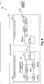
Fig. 8 shows an example of a configuration of part of a communication system in a sixth embodiment. - Embodiments of the present invention will be described in detail, with reference to drawings.
-
Fig. 1 shows an example of a configuration of acommunication system 1a. Thecommunication system 1a is a radio-over-fiber (ROF) system with a configuration of a passive optical network (PON). Thecommunication system 1a includes anaccess point 2a and wireless terminals 3-1 to 3-N (N is an integer equal to or larger than one). - The
access point 2a includes anaccommodation station device 20a, anoptical fiber 21, anoptical splitter 22, andextension station devices 23a-1 to 23a-M (M is an integer equal to or larger than two). Theextension station devices 23a are placed in such a manner that theextension station devices 23a extend outward from theaccommodation station device 20a. Theaccommodation station device 20a and theextension station devices 23a are separated from each other by using a radio-over-fiber technology. - The
accommodation station device 20a includes asignal processing unit 201, amulti-wavelength light source 202, and anoptical modulator 203. Eachextension station device 23a-m (m is any one of integers from one to M) includes anoptical demultiplexer 230a-m and optical detectors 231-m-1 to 231-m-P (P is an integer equal to or larger than two). Eachoptical detector 231 includes an antenna (transmission unit). - The
access point 2a is a communication device that connects one ormore wireless terminals 3 to a predetermined network through wireless communication. Theaccommodation station device 20a is a device that accommodates signals of a plurality ofwireless terminals 3 through wireless communication. Theoptical fiber 21 transmits an optical signal between theaccommodation station device 20a and eachextension station device 23a. Theoptical splitter 22 splits a downlink (downstream) optical signal transmitted in theoptical fiber 21. Theoptical splitter 22 multiplexes a plurality of uplink (upstream) optical signals transmitted in theoptical fiber 21. Theextension station devices 23a perform wireless communication with thewireless terminal 3. Thewireless terminal 3 is a terminal that performs wireless communication. - For the
communication system 1a to perform optical beamforming, it is not necessary to estimate an optical fiber length between every one of theextension station devices 23a and theaccommodation station device 20a in theaccess point 2a. Theaccommodation station device 20a estimates an optical fiber length between theaccommodation station device 20a and anextension station device 23a to which the wireless terminal 3 (station), with which theaccommodation station device 20a is communicating, is connected through wireless communication. Thecommunication system 1a performs optical beamforming, based on an estimated value of the optical fiber length of theoptical fiber 21 in which an optical signal is transmitted when theaccommodation station device 20a communicates with the wireless terminal 3-n. - Accordingly, using optical signals with mutually different wavelengths, the
accommodation station device 20a derives, for each optical signal wavelength, a round-trip transmission time period "Δt" (RoF-RTT) of signals (optical signal, radio-wave signal) between theaccommodation station device 20a and thewireless terminal 3, based on time information. Instead of theaccommodation station device 20a deriving the round-trip transmission time period, thewireless terminal 3 may derive the round-trip transmission time period "Δt" for each optical signal wavelength. Theaccommodation station device 20a estimates the optical fiber length, based on a difference between a round-trip transmission time period "Δt1" of communication using an optical signal with a first wavelength between theaccommodation station device 20a and thewireless terminal 3 and a round-trip transmission time period "Δt2" of communication using an optical signal with a second wavelength between theaccommodation station device 20a and thewireless terminal 3. -
Fig. 2 shows an example of a configuration of part of thecommunication system 1a. A portion or all of thesignal processing unit 201 are implemented as software in such a manner that a processor such as a CPU (Central Processing Unit) executes a program stored in a memory that is a non-volatile recording medium (non-transitory recording medium). A portion or all of thesignal processing unit 201 may be implemented by using hardware such as an LSI (Large Scale Integrated circuit) or an FPGA (Field Programmable Gate Array). - Any
extension station device 23a-m is communicationally connected to any wireless terminal 3-n with which theaccommodation station device 20a is communicating. Theaccommodation station device 20a estimates the optical fiber length "1" between theaccommodation station device 20a and theextension station device 23a-m, based on a round-trip transmission time period "2t1" of an optical signal with a wavelength "λ1" in an optical fiber segment, a round-trip transmission time period "2t2" of an optical signal with a wavelength "λ2" in the optical fiber segment, and a wait time period "ts" of thewireless terminal 3. The wait time period "ts" is a fixed value equal to or larger than zero. - When downlink communication using the optical signal with the wavelength "λ1" is started, the
accommodation station device 20a acquires time information as information on a communication start time "t1_tx". The optical signal with the wavelength "λ1" transmitted through theoptical fiber 21 is transmitted to one of the optical detectors 231-m via theoptical demultiplexer 230a-m that is a variable optical demultiplexer. The optical detector 231-m transmits a radio-wave signal according to the optical signal with the wavelength "λ1", at a predetermined frequency, from an antenna of the optical detector 231-m. An antenna of the wireless terminal 3-n receives the radio-wave signal transmitted from the antenna of the optical detector 231-m via the wireless segment. When the antenna of the wireless terminal 3-n is an array antenna, one antenna element included in the array antenna may receive the radio-wave signal based on the optical signal with the wavelength "λ1". At a time when the wait time period "ts" has passed since the radio-wave signal was received, the wireless terminal 3-n transmits a radio-wave signal in uplink communication from the antenna that has received the radio-wave signal in the downlink communication. - When downlink communication using the optical signal with the wavelength "λ2" is started, the
accommodation station device 20a acquires time information as information on a communication start time "t2_tx". The optical signal with the wavelength "λ2" transmitted through theoptical fiber 21 is transmitted to one of the optical detectors 231-m via theoptical demultiplexer 230a-m that is a variable optical demultiplexer. The optical detector 231-m transmits a radio-wave signal according to the optical signal with the wavelength "λ2", at a predetermined frequency, from an antenna of the optical detector 231-m. The antenna of the wireless terminal 3-n receives the radio-wave signal transmitted from the antenna of the optical detector 231-m via the wireless segment. When the antenna of the wireless terminal 3-n is an array antenna, one antenna element included in the array antenna may receive the radio-wave signal based on the optical signal with the wavelength "λ2". At a time when the wait time period "ts" has passed since the radio-wave signal was received, the wireless terminal 3-n transmits a radio-wave signal in uplink communication from the antenna that has received the radio-wave signal in the downlink communication. - The round-trip transmission time period "Δt1" in the case where the communication using the optical signal with the wavelength "λ1" is started is expressed by using the communication start time "t1_tx" and a reception time "t1_rx". In other words, the round-trip transmission time period "Δt1" is expressed by using the round-trip transmission time period "2t1" in the optical fiber segment, the wait time period "ts", and a round-trip transmission time period "2tr" of the radio-wave signals in the wireless segment.
- The round-trip transmission time period "Δt2" in the case where the communication using the optical signal with the wavelength "λ2" is started is expressed by using the communication start time "t2_tx" and a reception time "t2_rx". In other words, the round-trip transmission time period "Δt2" is expressed by using the round-trip transmission time period "2t2" in the optical fiber segment, the wait time period "ts", and the round-trip transmission time period "2tr" of the radio-wave signals in the wireless segment. Accordingly, the round-trip transmission time period "Δt1" and the round-trip transmission time period "Δt2" are expressed as in Expression (1).

- In measurement of the round-trip transmission time period "Δt1" and measurement of the round-trip transmission time period "Δt2", the
extension station device 23a-m uses the same antenna of theextension station device 23a-m. In the measurement of the round-trip transmission time period "Δt1" and the measurement of the round-trip transmission time period "Δt2", the wireless terminal 3-n uses the same antenna of the wireless terminal 3-n. In such cases, in the measurement of the round-trip transmission time period "Δt1" and the measurement of the round-trip transmission time period "Δt2", transmission distances of the radio-wave signals in the wireless segment are identical. In other words, the transmission time periods "tr" of the radio-wave signals in the wireless segment between the optical detectors 231-m and the wireless terminal 3-n are constant in the measurement of the round-trip transmission time period "Δt1" and the measurement of the round-trip transmission time period "Δt2". The transmission time periods "tr" of the radio-wave signals in the wireless segment are cancelled out, with a difference between the transmission time periods in the optical fiber segment remaining, and hence the difference between the round-trip transmission time period "Δt1" and the round-trip transmission time period "Δt2" is expressed as in Expression (2).
- Here, "2t1" represents the round-trip transmission time period of the optical signal with the wavelength "λ1" in the optical fiber segment including the
optical fiber 21. "2t2" represents the round-trip transmission time period of the optical signal with the wavelength "λ2" in the optical fiber segment including theoptical fiber 21. - A transmission rate (group velocity) of an optical signal in the optical fiber segment is determined depending on a type (material or the like) of the
optical fiber 21 and a wavelength of the optical signal. With respect to the round-trip time periods (round trip times) of the signals between theaccommodation station device 20a and thewireless terminal 3, the difference between the round-trip transmission time period "Δt1" and the round-trip transmission time period "Δt2" is expressed as in Expression (3), based on Expression (2).
- Here, "l" represents the optical fiber length. "v1" represents a transmission rate (group velocity) of the optical signal with the wavelength "λ1" in the optical fiber segment. "v2" represents a transmission rate (group velocity) of the optical signal with the wavelength "λ2" in the optical fiber segment. The optical fiber length "l" is expressed as in Expression (4).

- The
accommodation station device 20a derives the optical fiber length "1" as in Expression (4), based on the transmission rate "v1" and the transmission rate "v2" that are already known, and on the difference "Δt1 - Δt2" between the round-trip transmission time periods that are based on the acquired time information. - Next, details of the
accommodation station device 20a and thewireless terminal 3 will be described. -
Fig. 3 shows an example of a configuration of theaccommodation station device 20a. Theaccommodation station device 20a includes thesignal processing unit 201, the multi-wavelengthlight source 202, theoptical modulator 203, ademultiplexer 204, adetector 205, a transmission timeperiod derivation unit 206, an optical fiber length derivation unit 207, acontrol unit 208, and a fiberinformation storage unit 209. - The
signal processing unit 201 acquires time information. When downlink communication is started, thesignal processing unit 201 outputs information on a communication start time to the transmission timeperiod derivation unit 206. Thesignal processing unit 201 acquires, from thecontrol unit 208, control information for optical beamforming based on an estimated optical fiber length, and information on the wait time period "ts". The control information is, for example, weighting information for a phase of a radio signal to be transmitted from each antenna element. In uplink communication, when an electrical signal (hereinafter, referred to as "RF (Radio Frequency) signal") associated with a radio-wave signal is received, thesignal processing unit 201 outputs information on a communication start time and information on a reception time to the transmission timeperiod derivation unit 206. The RF signal includes information on the wait time period of thewireless terminal 3. The multi-wavelengthlight source 202 outputs light with a wavelength "λ" specified by thecontrol unit 208 to theoptical modulator 203. - The
optical modulator 203 receives the light with the wavelength "λ" from the multi-wavelengthlight source 202. Theoptical modulator 203 acquires a downlink RF signal from thesignal processing unit 201. Theoptical modulator 203 performs modulation processing according to the downlink RF signal on each of streams of light with mutually different wavelengths. Theoptical modulator 203 transmits, as a transmission signal, downlink optical signals that are results of the modulation processing to theextension station device 23a-m. - The
demultiplexer 204 receives, as a reception signal, a plurality of uplink optical signals from theextension station device 23a-m. Thedemultiplexer 204 demultiplexes the plurality of uplink optical signals. Thedemultiplexer 204 outputs each of the demultiplexed optical signals to thedetector 205. Thedetector 205 performs predetermined wave detection processing on each optical signal. Thedetector 205 outputs uplink RF signals that are results of the wave detection processing to thesignal processing unit 201. - When the
accommodation station device 20a starts downlink communication using an optical signal, the transmission timeperiod derivation unit 206 acquires information on a communication start time from thesignal processing unit 201. When theaccommodation station device 20a receives an uplink optical signal, the transmission timeperiod derivation unit 206 acquires information on a reception time from thesignal processing unit 201. The transmission timeperiod derivation unit 206 derives a difference between the round-trip transmission time periods of each optical signal, as in Expression (2). - The optical fiber length derivation unit 207 acquires information on group velocities from the fiber
information storage unit 209. The optical fiber length derivation unit 207 derives an optical fiber length as in Expressions (3) and (4), based on the derived transmission time periods and the group velocities. - The
control unit 208 specifies, to the multi-wavelengthlight source 202, a wavelength "λ" of an optical signal used in optical beamforming, based on the derived optical fiber length and control information for the optical beamforming. The fiberinformation storage unit 209 stores a data table beforehand in which information on wavelengths "λ" and group velocities are associated with each other. The fiberinformation storage unit 209 outputs, to the optical fiber length derivation unit 207, information on a group velocity associated with the wavelength "λ" specified by thecontrol unit 208 to the multi-wavelengthlight source 202. -
Fig. 4 shows an example of a configuration of thewireless terminal 3. Thewireless terminal 3 includes acontrol unit 30 and asignal processing unit 31. A portion or all of thecontrol unit 30 and thesignal processing unit 31 are implemented as software in such a manner that a processor such as a CPU executes a program stored in a memory that is a non-volatile recording medium (non-transitory recording medium). A portion or all of thecontrol unit 30 and thesignal processing unit 31 may be implemented by using hardware such as an LSI or an FPGA. - The
control unit 30 acquires information on the wait time period from thesignal processing unit 31. When the information on the wait time period is acquired, thecontrol unit 30 acquires current time information as information on a reception time. When the wait time period has passed since the reception time, thecontrol unit 30 outputs a transmission control signal to thesignal processing unit 31. - When a radio-wave signal (reception signal) based on a downlink optical signal is received, the
signal processing unit 31 acquires the information on the wait time period from the radio-wave signal. Thesignal processing unit 31 outputs the information on the wait time period to thecontrol unit 30. When the transmission control signal is acquired from thecontrol unit 30, thesignal processing unit 31 transmits a radio-wave signal (transmission signal) associated with an uplink optical signal to theaccommodation station device 20a. - Next, an example of operation in the
communication system 1a will be described. -
Fig. 5 is a sequence chart showing an example of the operation in thecommunication system 1a. Thesignal processing unit 201 generates RF signals including information on a wait time period (step S101) . Theoptical modulator 203 generates optical signals with wavelengths "λ" (step S102). Theoptical demultiplexer 230a acquires the optical signals via the optical fiber 21 (step S103). Corresponding ones of theoptical detectors 231 transmit downlink radio-wave signals by using the respective antennas (step S104). - The
optical detectors 231 receive uplink radio-wave signals by using the antennas that have transmitted the downlink radio-wave signals (step S105). When thesignal processing unit 201 acquires uplink RF signals, the transmission timeperiod derivation unit 206 acquires information on reception times at the signal processing unit 201 (step S106). The transmission timeperiod derivation unit 206 acquires information on communication start times (step S107). - The transmission time
period derivation unit 206 derives round-trip transmission time periods "Δt" (round trip times), based on the communication start times and the reception times. The transmission timeperiod derivation unit 206 derives a difference "Δt1 - Δt2" between the round-trip transmission time periods of the signals (step S108). The optical fiber length derivation unit 207 derives an optical fiber length between anextension station device 23a including the antennas that have transmitted the downlink radio-wave signals and theaccommodation station device 20a, based on the difference between the round-trip transmission time periods "Δt" of the signals (step S109). - The
signal processing unit 31 receives the radio-wave signals (reception signal) based on the downlink optical signals (step S201). Thesignal processing unit 31 performs demodulation processing on the received radio-wave signals. Thesignal processing unit 31 acquires the information on the wait time period from the radio-wave signals (step S202). Thesignal processing unit 31 waits to transmit the radio-wave signals associated with uplink optical signals until the transmission control signal is received from the control unit 30 (step S203). When a transmission control signal is received from thecontrol unit 30, thesignal processing unit 31 transmits the radio-wave signals associated with the uplink optical signals (step S204). - As described above, the
communication system 1a in the first embodiment includes theaccess point 2a and the one ormore wireless terminals 3. Theaccess point 2a includes theaccommodation station device 20a and theextension station devices 23a connected to each other through theoptical fiber 21 transmitting optical signals. Thewireless terminal 3 communicates with theextension station devices 23a by using a radio-wave signal. Theaccommodation station device 20a includes the transmission time period derivation unit 206 (communication start time information acquisition unit, reception time information acquisition unit), and the optical fiber length derivation unit 207. The antenna of anyextension station device 23a transmits, to thewireless terminal 3, the first radio-wave signal according to the optical signal with the first wavelength "λ1" and the second radio-wave signal according to the optical signal with the second wavelength "λ2". The transmission timeperiod derivation unit 206 acquires information on the first communication start time that is a time at which communication using the optical signal with the first wavelength is started in theaccommodation station device 20a, and information on the second communication start time that is a time at which communication using the optical signal with the second wavelength is started in theaccommodation station device 20a. The transmission timeperiod derivation unit 206 acquires information on the first reception time that is a reception time related to the first radio-wave signal in theaccommodation station device 20a, and information on the second reception time that is a reception time related to the second radio-wave signal in theaccommodation station device 20a. The transmission timeperiod derivation unit 206 derives the first round trip time "Δt1" that is a time period from the first communication start time "t1_tx" until the first reception time "t1_rx" . The transmission timeperiod derivation unit 206 derives the second round trip time "Δt2" that is a time period from the second communication start time "t2_tx" until the second reception time "t2_rx". The optical fiber length derivation unit 207 derives the optical fiber length "1", based on the first round trip time "Δt1", the second round trip time "Δt2", the group velocity "v1" of the optical signal with the first wavelength, and the group velocity "v2" of the optical signal with the second wavelength. - Thus, it is possible to estimate the optical fiber length "1" between the
accommodation station device 20a and anyextension station device 23a, without theextension station device 23a including thesignal processing unit 201. - The optical fiber length derivation unit 207 derives the optical fiber length "1" as in Expression (4), based on the difference "Δt1 - Δt2" between the first round trip time and the second round trip time, the group velocity "v1" of the optical signal with the first wavelength, and the group velocity "v2" of the optical signal with the second wavelength.
- A second embodiment is different from the first embodiment in a point that optical signals with wavelengths that are mutually different between an uplink and a downlink and radio-wave signals with frequencies that are mutually different between the uplink and the downlink are used. In the second embodiment, the point different from the first embodiment will be described.
- In the first embodiment, the
accommodation station device 20a or thewireless terminal 3 derives transmission time periods of optical signals with mutually different wavelengths in a downlink between theaccommodation station device 20a and thewireless terminal 3. In the second embodiment, theaccommodation station device 20a derives a difference between round-trip transmission time periods of optical signals, by using optical signals with wavelengths that are mutually different between an uplink and a downlink between theaccommodation station device 20a and thewireless terminal 3. Theaccommodation station device 20a or thewireless terminal 3 estimates an optical fiber length, based on the derived difference between the transmission time periods. - In downlink communication, the
wireless terminal 3 receives a radio-wave signal with a frequency "fDL". In uplink communication, when the wait time period has passed since the reception time, thewireless terminal 3 transmits a radio-wave signal with a frequency "fUL". The frequency "fUL" of the uplink radio-wave signal and the frequency "fDL" of the downlink radio-wave signal may be different from each other. Even when the uplink and downlink radio-wave signals have the different frequencies, transmission time periods "tr" in the wireless segment are constant. Accordingly, as in the first embodiment, the optical fiber length can be estimated based on communication start times and reception times. -
Fig. 6 shows an example of a configuration of part of thecommunication system 1a. Anyextension station device 23a-m is communicationally connected to any wireless terminal 3-n with which theaccommodation station device 20a is communicating. Theaccommodation station device 20a estimates the optical fiber length "1" between theaccommodation station device 20a and theextension station device 23a-m, based on a downlink transmission time period "t1" of an optical signal with a wavelength "λ1" in the optical fiber segment, a downlink transmission time period "t2" of an optical signal with a wavelength "λ2" in the optical fiber segment, an uplink transmission time period "t3" of an optical signal with a wavelength "λ3" in the optical fiber segment, an uplink transmission time period "t4" of an optical signal with a wavelength "λ4" in the optical fiber segment, a round-trip transmission time period "2tr" of the radio-wave signals in the wireless segment, and a wait time period "ts" of thewireless terminal 3. The wait time period "ts" is a fixed value. A round-trip transmission time period "Δt1" and a round-trip transmission time period "Δt2" are expressed as in Expression (5).
- A difference between the round-trip transmission time period "Δt1" and the round-trip transmission time period "Δt2" is expressed as in Expression (6).

- The difference between the round-trip transmission time period "Δt1" and the round-trip transmission time period "Δt2" is expressed as in Expression (7), based on Expression (6).

- Here, "1" represents the optical fiber length. "v1" represents a transmission rate (group velocity) of the optical signal with the wavelength "λ1" in the optical fiber segment. "v2" represents a transmission rate (group velocity) of the optical signal with the wavelength "λ2" in the optical fiber segment. "v3" represents a transmission rate (group velocity) of the optical signal with the wavelength "λ3" in the optical fiber segment. "'v4" represents a transmission rate (group velocity) of the optical signal with the wavelength "λ4" in the optical fiber segment. The optical fiber length "l" is expressed as in Expression (8).

- The
accommodation station device 20a derives the optical fiber length "l" as in Expression (8), based on the transmission rate "v1", the transmission rate "v2", the transmission rate "v3", and the transmission rate "v4" that are already known, and on the difference "Δt1 - Δt2" between the round-trip transmission time periods that are based on acquired time information. - As described above, the optical fiber length derivation unit 207 in the second embodiment derives the optical fiber length "l" as in Expression (8), based on the difference between the first round trip time "Δt1" and the second round trip time "Δt2", the group velocity "v1" of the optical signal with the first wavelength, the group velocity "v2" of the optical signal with the second wavelength, the group velocity "v3" of the optical signal with the third wavelength, and the group velocity "v4" of the optical signal with the fourth wavelength.
- Thus, it is possible to estimate the optical fiber length "l" between the
accommodation station device 20a and anyextension station device 23a, by using optical signals with wavelengths that are mutually different between an uplink and a downlink, without theextension station device 23a including thesignal processing unit 201. - A third embodiment is different from the first embodiment in a point that a group delay time is used instead of a group velocity, in estimation of an optical fiber length. In the third embodiment, the point different from the first embodiment will be described.
- In estimation of the optical fiber length "l", a group delay time may be used instead of a group velocity. A group delay time is a transmission time period per unit length, and is represented by a reciprocal of a group velocity. A group delay time of an optical signal in the optical fiber segment is determined depending on a type of the
optical fiber 21 and a wavelength of the optical signal. Expression (7) is expressed as in Expression (9).
- Here, "τ1" represents a group delay time of the optical signal with the wavelength "λ1" in the optical fiber segment. "τ2" represents a group delay time of the optical signal with the wavelength "λ2" in the optical fiber segment. The optical fiber length "l" is expressed as in Expression (10).

- The fiber
information storage unit 209 stores information on the group delay times. Theaccommodation station device 20a derives the optical fiber length "l" as in Expression (10), based on the group delay time "τ1" and the group delay time "τ2" that are already known, and on the round-trip transmission time period "Δt1" and the round-trip transmission time period "Δt2" that are based on acquired time information. - In such manners, the transmission time
period derivation unit 206 derives transmission time periods of the optical signals as in Expressions (1) and (2), based on communication start times and reception times. The optical fiber length derivation unit 207 acquires the information on the group delay times from the fiberinformation storage unit 209. The optical fiber length derivation unit 207 derives the optical fiber length as in Expressions (9) and (10), based on the derived transmission time periods and the group delay times. - As described above, the optical fiber length derivation unit 207 in the third embodiment derives the optical fiber length "l" as in Expression (10), based on the first round trip time "Δt1", the second round trip time "Δt2", the group delay time "τ1" of the optical signal with the first wavelength, and the group delay time "τ2" of the optical signal with the second wavelength.
- Thus, it is possible to estimate the optical fiber length "l" between the
accommodation station device 20a and anyextension station device 23a, based on group delay times, without theextension station device 23a including thesignal processing unit 201. - The optical fiber length derivation unit 207 derives the optical fiber length "l" as in Expression (10), based on the difference "Δt1 - Δt2" between the first round trip time and the second round trip time, the group delay time "τ1" of the optical signal with the first wavelength, and the group delay time "τ2" of the optical signal with the second wavelength.
- A fourth embodiment is different from the third embodiment in a point that optical signals with wavelengths that are mutually different between an uplink and a downlink and radio-wave signals with frequencies that are mutually different between the uplink and the downlink are used. In the fourth embodiment, the point different from the third embodiment will be described.
- In the third embodiment, the
accommodation station device 20a or thewireless terminal 3 derives round-trip transmission time periods of optical signals with wavelengths that are identical in an uplink and a downlink between theaccommodation station device 20a and thewireless terminal 3. In the fourth embodiment, theaccommodation station device 20a or thewireless terminal 3 derives round-trip transmission time periods of optical signals with wavelengths that are mutually different between an uplink and a downlink between theaccommodation station device 20a and thewireless terminal 3. Theaccommodation station device 20a or thewireless terminal 3 estimates an optical fiber length, based on a difference between the derived round-trip transmission time periods. - Any
extension station device 23a-m is communicationally connected to any wireless terminal 3-n with which theaccommodation station device 20a is communicating. Theaccommodation station device 20a estimates the optical fiber length "l" between theaccommodation station device 20a and theextension station device 23a-m, based on a downlink transmission time period "t1" of an optical signal with a wavelength "λ1" in the optical fiber segment, a downlink transmission time period "t2" of an optical signal with a wavelength "λ2" in the optical fiber segment, an uplink transmission time period "t3" of an optical signal with a wavelength "λ3" in the optical fiber segment, an uplink transmission time period "t4" of an optical signal with a wavelength "λ4" in the optical fiber segment, a round-trip transmission time period "2tr" of radio-wave signals in the wireless segment, and a wait time period "ts" of thewireless terminal 3. The wait time period "ts" is a fixed value. - When downlink communication using the optical signal with the wavelength "λ1" is started, the
accommodation station device 20a acquires time information as information on a communication start time "t1_tx". The optical signal with the wavelength "λ1" transmitted through theoptical fiber 21 is transmitted to one of the optical detectors 231-m via theoptical demultiplexer 230a-m that is a variable optical demultiplexer. The optical detector 231-m transmits a radio-wave signal according to the optical signal with the wavelength "λ1", at a predetermined frequency, from an antenna of the optical detector 231-m. An antenna of the wireless terminal 3-n receives the radio-wave signal with the frequency "fDL" transmitted from the antenna of the optical detector 231-m via the wireless segment. When the antenna of the wireless terminal 3-n is an array antenna, one antenna element included in the array antenna may receive the radio-wave signal based on the optical signal with the wavelength "λ1". At a time when the wait time period "ts" has passed since the radio-wave signal was received, the wireless terminal 3-n transmits a radio-wave signal with a frequency "fUL" in uplink communication from the antenna that has received the radio-wave signal in the downlink communication. Theextension station device 23a receives the radio-wave signal with the frequency "fUL" in the uplink communication at an antenna of one of the optical detectors 231-m. Theaccommodation station device 20a acquires the optical signal with the wavelength "λ3" from the optical detector 231-m. - The
accommodation station device 20a operates similarly in communication using the optical signal with the wavelength "λ2" and the optical signal with the wavelength "λ4", as in the communication using the optical signal with the wavelength "λ1" and the optical signal with the wavelength "λ3". - A group delay time of an optical signal in the optical fiber segment is determined depending on a type of the
optical fiber 21 and a wavelength of the optical signal. Expression (7) is expressed as in Expression (11).
- Here, "l" represents the optical fiber length. "τ1" represents a group delay time of the downlink optical signal with the wavelength "λ1" in the optical fiber segment. "τ2" represents a group delay time of the downlink optical signal with the wavelength "λ2" in the optical fiber segment. "τ3" represents a group delay time of the uplink optical signal with the wavelength "λ3" in the optical fiber segment. "τ4" represents a group delay time of the uplink optical signal with the wavelength "λ4" in the optical fiber segment. The optical fiber length "1" is expressed as in Expression (12).

- The
accommodation station device 20a derives the optical fiber length "l" as in Expression (12), based on the group delay time "τ1', the group delay time "τ2", the group delay time "τ3", the group delay time "τ4", and the difference "Δt1 - Δt2" between the round-trip transmission time periods that are based on acquired time information. - As described above, the optical fiber length derivation unit 207 in the fourth embodiment derives the optical fiber length "l" as in Expression (12), based on the difference between the first round trip time "Δt1" and the second round trip time "Δt2", the group delay time "τ1" of the optical signal with the first wavelength, the group delay time "τ2" of the optical signal with the second wavelength, the group delay time "τ3" of the optical signal with the third wavelength, and the group delay time "τ4" of the optical signal with the fourth wavelength.
- Thus, it is possible to estimate the optical fiber length "l" between the
accommodation station device 20a and anyextension station device 23a, by using optical signals with wavelengths that are mutually different between an uplink and a downlink and radio-wave signals with frequencies that are mutually different between the uplink and the downlink, without theextension station device 23a including thesignal processing unit 201. - A fifth embodiment is different from the first embodiment in a point that an accommodation station device includes a plurality of light sources with fixed wavelengths, instead of the multi-wavelength light source. In the fifth embodiment, the point different from the first embodiment will be described.
-
Fig. 7 shows an example of a configuration of acommunication system 1b. Thecommunication system 1b is a radio-over-fiber (ROF) system with a configuration of a passive optical network (PON). Thecommunication system 1b includes anaccess point 2b and wireless terminals 3-1 to 3-N. Theaccess point 2b is a communication device that connects one ormore wireless terminals 3 to a predetermined network through wireless communication. - The
access point 2b includes anaccommodation station device 20b, anoptical fiber 21, anoptical splitter 22, andextension station devices 23b-1 to 23b-M. Theaccommodation station device 20b includes asignal processing unit 201, optical modulators 203-1 to 203-W (W is an integer equal to or larger than two), light sources 210-1 to 210-W, and anoptical multiplexer 211. - Each light source 210-w (w is any one of integers from 2 to W) is a light source with a fixed wavelength. The light source 210-w is connected to an optical modulator 203-w. The light source 210-w generates an optical signal, according to a signal outputted from the
signal processing unit 201. - The
optical multiplexer 211 multiplexes respective optical signals generated by the light sources 210-1 to 210-W. Theoptical multiplexer 211 transmits the optical signal with the wavelength "λ1" to anyextension station device 23a-m, according to a result of the multiplexing of the optical signals. Theoptical multiplexer 211 transmits the optical signal with the wavelength "λ2" to theextension station device 23a-m, according to the result of the multiplexing. - As described above, the
accommodation station device 20b in the fifth embodiment includes the light sources 210-1 to 210-W. The plurality oflight sources 210 output streams of light with the fixed wavelengths ranging from the wavelength "λ1" to a wavelength "λL" to the plurality ofoptical modulators 203 associated with thelight sources 210, respectively. Thus, it is possible to estimate the optical fiber length "l" between theaccommodation station device 20b and anyextension station device 23b, without theextension station device 23b including thesignal processing unit 201. - A sixth embodiment is different from the fifth embodiment in a point that each extension station device includes an optical demultiplexer for fixed wavelengths, instead of the variable optical demultiplexer. In the sixth embodiment, the point different from the fifth embodiment will be described.
-
Fig. 8 shows an example of a configuration of acommunication system 1c. Thecommunication system 1c is a radio-over-fiber (ROF) system with a configuration of a passive optical network (PON). Thecommunication system 1c includes anaccess point 2c and wireless terminals 3-1 to 3-N. Theaccess point 2c is a communication device that connects one ormore wireless terminals 3 to a predetermined network through wireless communication. - The
access point 2c includes anaccommodation station device 20c, anoptical fiber 21, anoptical splitter 22, andextension station devices 23c-1 to 23cM. Eachextension station device 23c includes anoptical demultiplexer 230c, one or moreoptical switches 232, and one or moreoptical detectors 231. - The
optical demultiplexer 230c is an optical demultiplexer for fixed wavelengths. Theoptical demultiplexer 230c outputs the optical signal with the wavelength "λ1" and the optical signal with the wavelength "λ2" to theoptical switch 232. Theoptical switch 232 outputs, to theoptical detector 231, the optical signal with the selected wavelength of the wavelength "λ1" and the wavelength "λ2". Theoptical detector 231 transmits a radio-wave signal according to the optical signal with the selected wavelength, at a predetermined frequency, from an antenna of the optical detector 231-m. Note that all optical fibers between theoptical demultiplexer 230c and theoptical switches 232 have the same length. - As described above, each
extension station device 23c in the sixth embodiment includes the one or moreoptical switches 232 and the one or moreoptical detectors 231. Theoptical detector 231 transmits a radio-wave signal according to an optical signal of a selected wavelength, at a predetermined frequency, from an antenna of the optical detector 231-m. Thus, it is possible to estimate the optical fiber length "l" between theaccommodation station device 20c and anyextension station device 23c, without theextension station device 23c including thesignal processing unit 201. - A seventh embodiment is different from the first embodiment in a point that transmission time periods "tr" of radio-wave signals in a wireless segment are not constant. In the seventh embodiment, the point different from the first embodiment will be described.
- When transmission time periods "tr" of radio-wave signals in the wireless segment are not constant due to movement of the
wireless terminal 3, an error in estimation of the optical fiber length "l" occurs according to a movement distance over which thewireless terminal 3 has moved. Accordingly, an allowance for the movement distance, or a movement speed, of thewireless terminal 3 is set, depending on an estimation error allowed in thecommunication system 1a. Thewireless terminal 3 moves within a range of the allowance for the movement distance or the movement speed. Theaccommodation station device 20a estimates the optical fiber length "l", based on optical signals received from anextension station device 23a that is communicating with thewireless terminal 3 moving within the range of the allowance. - As described above, the optical fiber length derivation unit 207 in the seventh embodiment derives the optical fiber length "l", based on the optical signals received from the
extension station device 23a that is communicating with thewireless terminal 3 moving within the range of the allowance. The optical fiber length derivation unit 207 determines whether or not thewireless terminal 3 moves within the range of the allowance, for example, based on a result of positioning by a positioning system that uses radio waves transmitted from artificial satellites. Thus, it is possible to estimate the optical fiber length "l" between the accommodation station device and any extension station device, without theextension station device 23a including thesignal processing unit 201. Note that each embodiment may be combined with one another. - Although the embodiments of the present invention have been described above with reference to the drawings, specific configurations are not limited to such embodiments, and include designs and the like within a scope that does not depart from the gist of the present invention.
- The present invention is applicable to optical wireless communication systems.
-
- 1a, 1b, 1c
- Communication system
- 2a, 2b
- Access point
- 3
- Wireless terminal
- 20a, 20b, 20c
- Accommodation station device
- 21
- Optical fiber
- 22
- Optical splitter
- 23a, 23b, 23c
- Extension station device
- 30
- Control unit
- 31
- Signal processing unit
- 201
- Signal processing unit
- 202
- Multi-wavelength light source
- 203
- Optical modulator
- 204
- Demultiplexer
- 205
- Detector
- 206
- Transmission time period derivation unit
- 207
- Optical fiber length derivation unit
- 208
- Control unit
- 209
- Fiber information storage unit
- 210
- Light source
- 211
- Optical multiplexer
- 230a, 230b, 230c
- Optical demultiplexer
- 231
- Optical detector
- 232
- Optical switch
Claims (5)
- A derivation method performed by a communication system including an access point and a wireless terminal, the access point including an accommodation station device and an extension station device connected to each other through an optical fiber transmitting an optical signal, and the wireless terminal communicating with the extension station device by using a radio-wave signal, the derivation method comprising:a transmission step of transmitting, to the wireless terminal, a first radio-wave signal according to an optical signal with a first wavelength, and a second radio-wave signal according to an optical signal with a second wavelength;a communication start time information acquisition step of acquiring information on a first communication start time that is a time at which communication using the optical signal with the first wavelength is started in the accommodation station device, and information on a second communication start time that is a time at which communication using the optical signal with the second wavelength is started in the accommodation station device;a reception time information acquisition step of acquiring information on a first reception time that is a reception time related to the first radio-wave signal in the accommodation station device, and information on a second reception time that is a reception time related to the second radio-wave signal in the accommodation station device;a transmission time period derivation step of deriving a first round trip time that is a time period from the first communication start time until the first reception time, and deriving a second round trip time that is a time period from the second communication start time until the second reception time; andan optical fiber length derivation step of deriving a length of the optical fiber, based on the first round trip time, the second round trip time, a group velocity or a group delay time of the optical signal with the first wavelength, and a group velocity or a group delay time of the optical signal with the second wavelength.
- The derivation method according to claim 1, wherein the optical fiber length derivation step derives the length of the optical fiber, based on a difference between the first round trip time and the second round trip time, the group velocity or the group delay time of the optical signal with the first wavelength, and the group velocity or the group delay time of the optical signal with the second wavelength.
- The derivation method according to claim 1, wherein the optical fiber length derivation step derives the length of the optical fiber, based on a difference between the first round trip time and the second round trip time, the group velocity or the group delay time of the optical signal with the first wavelength, the group velocity or the group delay time of the optical signal with the second wavelength, a group velocity or a group delay time of an optical signal with a third wavelength, and a group velocity or a group delay time of an optical signal with a fourth wavelength.
- A communication system, comprising:an access point including an accommodation station device and an extension station device connected to each other through an optical fiber transmitting an optical signal; anda wireless terminal that communicates with the extension station device by using a radio-wave signal,wherein the accommodation station device includesa transmission unit that transmits, to the wireless terminal, a first radio-wave signal according to an optical signal with a first wavelength, and a second radio-wave signal according to an optical signal with a second wavelength,a communication start time information acquisition unit that acquires information on a first communication start time that is a time at which communication using the optical signal with the first wavelength is started in the accommodation station device, and information on a second communication start time that is a time at which communication using the optical signal with the second wavelength is started in the accommodation station device,a reception time information acquisition unit that acquires information on a first reception time that is a reception time related to the first radio-wave signal in the accommodation station device, and information on a second reception time that is a reception time related to the second radio-wave signal in the accommodation station device,a transmission time period derivation unit that derives a first round trip time that is a time period from the first communication start time until the first reception time, and derives a second round trip time that is a time period from the second communication start time until the second reception time, andan optical fiber length derivation unit that derives a length of the optical fiber, based on the first round trip time, the second round trip time, a group velocity or a group delay time of the optical signal with the first wavelength, and a group velocity or a group delay time of the optical signal with the second wavelength.
- An accommodation station device in a communication system including an access point and a wireless terminal, the access point including the accommodation station device and an extension station device connected to each other through an optical fiber transmitting an optical signal, and the wireless terminal communicating with the extension station device by using a radio-wave signal, the accommodation station device comprising:a transmission unit that transmits, to the wireless terminal, a first radio-wave signal according to an optical signal with a first wavelength, and a second radio-wave signal according to an optical signal with a second wavelength;a communication start time information acquisition unit that acquires information on a first communication start time that is a time at which communication using the optical signal with the first wavelength is started in the accommodation station device, and information on a second communication start time that is a time at which communication using the optical signal with the second wavelength is started in the accommodation station device;a reception time information acquisition unit that acquires information on a first reception time that is a reception time related to the first radio-wave signal in the accommodation station device, and information on a second reception time that is a reception time related to the second radio-wave signal in the accommodation station device;a transmission time period derivation unit that derives a first round trip time that is a time period from the first communication start time until the first reception time, and derives a second round trip time that is a time period from the second communication start time until the second reception time; andan optical fiber length derivation unit that derives a length of the optical fiber, based on the first round trip time, the second round trip time, a group velocity or a group delay time of the optical signal with the first wavelength, and a group velocity or a group delay time of the optical signal with the second wavelength.
Applications Claiming Priority (2)
| Application Number | Priority Date | Filing Date | Title |
|---|---|---|---|
| JP2019025671A JP7223229B2 (en) | 2019-02-15 | 2019-02-15 | Derivation method, communication system and accommodation station device |
| PCT/JP2020/003611 WO2020166379A1 (en) | 2019-02-15 | 2020-01-31 | Derivation method, communication system, and accommodating station device |
Publications (3)
| Publication Number | Publication Date |
|---|---|
| EP3907908A1 true EP3907908A1 (en) | 2021-11-10 |
| EP3907908A4 EP3907908A4 (en) | 2022-10-19 |
| EP3907908B1 EP3907908B1 (en) | 2023-12-27 |
Family
ID=72044099
Family Applications (1)
| Application Number | Title | Priority Date | Filing Date |
|---|---|---|---|
| EP20756641.5A Active EP3907908B1 (en) | 2019-02-15 | 2020-01-31 | Derivation method, communication system and accommodation station apparatus |
Country Status (4)
| Country | Link |
|---|---|
| US (1) | US11804901B2 (en) |
| EP (1) | EP3907908B1 (en) |
| JP (1) | JP7223229B2 (en) |
| WO (1) | WO2020166379A1 (en) |
Families Citing this family (3)
| Publication number | Priority date | Publication date | Assignee | Title |
|---|---|---|---|---|
| US20240405910A1 (en) * | 2021-01-27 | 2024-12-05 | Nippon Telegraph And Telephone Corporation | Wireless communication method and wireless communication apparatus |
| WO2022244045A1 (en) * | 2021-05-17 | 2022-11-24 | 日本電信電話株式会社 | Radio communication method and radio communication system |
| WO2025074622A1 (en) * | 2023-10-06 | 2025-04-10 | 日本電信電話株式会社 | Communication system and time estimation method |
Family Cites Families (19)
| Publication number | Priority date | Publication date | Assignee | Title |
|---|---|---|---|---|
| US5805983A (en) * | 1996-07-18 | 1998-09-08 | Ericsson Inc. | System and method for equalizing the delay time for transmission paths in a distributed antenna network |
| US7047028B2 (en) * | 2002-11-15 | 2006-05-16 | Telefonaktiebolaget Lm Ericsson (Publ) | Optical fiber coupling configurations for a main-remote radio base station and a hybrid radio base station |
| KR100724882B1 (en) * | 2005-02-18 | 2007-06-04 | 삼성전자주식회사 | Network system interworking X-LAN and 3x mobile communication network through optical wireless link and authentication method according to inter-network interworking in the network system |
| JP4246724B2 (en) | 2005-08-31 | 2009-04-02 | 日本電信電話株式会社 | Beam forming type ROF system |
| WO2009118878A1 (en) * | 2008-03-28 | 2009-10-01 | 富士通アクセス株式会社 | Pon system |
| US7961689B2 (en) | 2008-08-18 | 2011-06-14 | Adc Telecommunications, Inc. | Method and apparatus for determining an end of a subframe in a TDD system |
| CN103379437A (en) | 2012-04-28 | 2013-10-30 | 华为终端有限公司 | Wireless terminal positioning method, related device and related system |
| WO2013170910A1 (en) * | 2012-05-16 | 2013-11-21 | Telefonaktiebolaget L M Ericsson (Publ) | Determining properties of an optical communications path in an optical communications network |
| JP5759420B2 (en) * | 2012-06-12 | 2015-08-05 | 日本電信電話株式会社 | Optical communication system and new connection terminal detection method |
| US9131289B2 (en) * | 2012-06-21 | 2015-09-08 | NEC Laboratores America, Inc. | Software-defined optical network |
| US9955361B2 (en) * | 2013-02-26 | 2018-04-24 | Dali Systems Co., Ltd. | Method and system for WI-FI data transmission |
| US20170279577A1 (en) * | 2016-03-23 | 2017-09-28 | Corning Optical Communications Wireless Ltd | Assigning unique temporal delays to signal paths assigned to remote units in a wireless distribution system (wds), particularly for supporting location services for client devices |
| JP2017225018A (en) * | 2016-06-16 | 2017-12-21 | 三菱電機株式会社 | Subscriber side apparatus, station side apparatus, optical communication system, optical communication method, and program |
| US10291298B2 (en) * | 2017-04-18 | 2019-05-14 | Corning Optical Communications LLC | Remote unit supporting radio frequency (RF) spectrum-based coverage area optimization in a wireless distribution system (WDS) |
| US10693559B2 (en) | 2017-10-05 | 2020-06-23 | Cable Television Laboratories, Inc | System and methods for centralized network node digitization |
| JP7137073B2 (en) | 2018-12-19 | 2022-09-14 | 日本電信電話株式会社 | Wireless communication system, access point device, wireless station device, and wireless communication method |
| JP7071642B2 (en) | 2018-12-19 | 2022-05-19 | 日本電信電話株式会社 | Optical wireless communication system, wireless transmitter / receiver and optical wireless communication method |
| US11146351B1 (en) | 2019-08-29 | 2021-10-12 | Cable Television Laboratories, Inc. | Photonics assisted millimeter-wave systems and methods |
| JP7328578B2 (en) | 2019-11-25 | 2023-08-17 | 日本電信電話株式会社 | Radio transmission system, radio reception system, base station apparatus, radio communication system, radio transmission method, and radio reception method |
-
2019
- 2019-02-15 JP JP2019025671A patent/JP7223229B2/en active Active
-
2020
- 2020-01-31 EP EP20756641.5A patent/EP3907908B1/en active Active
- 2020-01-31 US US17/429,582 patent/US11804901B2/en active Active
- 2020-01-31 WO PCT/JP2020/003611 patent/WO2020166379A1/en not_active Ceased
Also Published As
| Publication number | Publication date |
|---|---|
| EP3907908A4 (en) | 2022-10-19 |
| US20220140905A1 (en) | 2022-05-05 |
| WO2020166379A1 (en) | 2020-08-20 |
| JP2020136819A (en) | 2020-08-31 |
| EP3907908B1 (en) | 2023-12-27 |
| JP7223229B2 (en) | 2023-02-16 |
| US11804901B2 (en) | 2023-10-31 |
Similar Documents
| Publication | Publication Date | Title |
|---|---|---|
| EP3907908B1 (en) | Derivation method, communication system and accommodation station apparatus | |
| EP3893414B1 (en) | Wireless communication system, accommodation station device, and wireless communication method | |
| EP3761528B1 (en) | Space optical communication device | |
| EP3064956B1 (en) | Fully optically controlled phased array radar transmitter | |
| EP3055938B1 (en) | Systems and methods for delay management in distributed antenna system with direct digital interface to base station | |
| EP0738055B1 (en) | Phase synchronization system | |
| EP3132651B1 (en) | A first network node, a second network node and methods therein | |
| EP3373391B1 (en) | Phased array antenna | |
| EP3164953B1 (en) | Feed signal generation for a phased array antenna | |
| EP3902159B1 (en) | Derivation method, communication system and accommodation station apparatus | |
| US12052679B2 (en) | Wireless communication system, access point apparatus, wireless station apparatus and wireless communication method | |
| JP7071642B2 (en) | Optical wireless communication system, wireless transmitter / receiver and optical wireless communication method | |
| US7024120B2 (en) | Phase tracking multichannel link | |
| EP4344078A1 (en) | Radio communication method and radio communication system | |
| JP7323826B2 (en) | Radio transmission system, radio reception system, base station apparatus, radio communication system, radio transmission method, and radio reception method | |
| EP3382797B1 (en) | Phased array antenna | |
| US20250007562A1 (en) | A method for transmission of downlink radio signals in a d-mimo system and a d-mimo system | |
| US11736191B2 (en) | Wireless communication system, accommodation apparatus and wireless communication method | |
| EP4344079A1 (en) | Wireless communication method and wireless communication system | |
| WO2022053133A1 (en) | Lambda tuned disaggregated optical time domain reflectometry | |
| EP4510470A1 (en) | Wireless communication method, base station device, and wireless communication system | |
| JP2001086057A (en) | Wireless communication system | |
| WO2025074622A1 (en) | Communication system and time estimation method | |
| JP7333295B2 (en) | Radio systems and equipment for such radio systems | |
| EP4362527A1 (en) | Wireless communication method |
Legal Events
| Date | Code | Title | Description |
|---|---|---|---|
| STAA | Information on the status of an ep patent application or granted ep patent |
Free format text: STATUS: THE INTERNATIONAL PUBLICATION HAS BEEN MADE |
|
| PUAI | Public reference made under article 153(3) epc to a published international application that has entered the european phase |
Free format text: ORIGINAL CODE: 0009012 |
|
| STAA | Information on the status of an ep patent application or granted ep patent |
Free format text: STATUS: REQUEST FOR EXAMINATION WAS MADE |
|
| 17P | Request for examination filed |
Effective date: 20210805 |
|
| AK | Designated contracting states |
Kind code of ref document: A1 Designated state(s): AL AT BE BG CH CY CZ DE DK EE ES FI FR GB GR HR HU IE IS IT LI LT LU LV MC MK MT NL NO PL PT RO RS SE SI SK SM TR |
|
| DAV | Request for validation of the european patent (deleted) | ||
| DAX | Request for extension of the european patent (deleted) | ||
| A4 | Supplementary search report drawn up and despatched |
Effective date: 20220915 |
|
| RIC1 | Information provided on ipc code assigned before grant |
Ipc: H04W 88/08 20090101ALI20220909BHEP Ipc: H04B 7/06 20060101ALI20220909BHEP Ipc: H04B 10/077 20130101ALI20220909BHEP Ipc: H04W 92/12 20090101ALI20220909BHEP Ipc: H04W 16/26 20090101ALI20220909BHEP Ipc: H04B 10/07 20130101ALI20220909BHEP Ipc: H04B 10/2575 20130101AFI20220909BHEP |
|
| GRAP | Despatch of communication of intention to grant a patent |
Free format text: ORIGINAL CODE: EPIDOSNIGR1 |
|
| STAA | Information on the status of an ep patent application or granted ep patent |
Free format text: STATUS: GRANT OF PATENT IS INTENDED |
|
| INTG | Intention to grant announced |
Effective date: 20230719 |
|
| GRAS | Grant fee paid |
Free format text: ORIGINAL CODE: EPIDOSNIGR3 |
|
| GRAA | (expected) grant |
Free format text: ORIGINAL CODE: 0009210 |
|
| STAA | Information on the status of an ep patent application or granted ep patent |
Free format text: STATUS: THE PATENT HAS BEEN GRANTED |
|
| AK | Designated contracting states |
Kind code of ref document: B1 Designated state(s): AL AT BE BG CH CY CZ DE DK EE ES FI FR GB GR HR HU IE IS IT LI LT LU LV MC MK MT NL NO PL PT RO RS SE SI SK SM TR |
|
| REG | Reference to a national code |
Ref country code: GB Ref legal event code: FG4D |
|
| REG | Reference to a national code |
Ref country code: CH Ref legal event code: EP |
|
| REG | Reference to a national code |
Ref country code: DE Ref legal event code: R096 Ref document number: 602020023448 Country of ref document: DE |
|
| REG | Reference to a national code |
Ref country code: IE Ref legal event code: FG4D |
|
| PG25 | Lapsed in a contracting state [announced via postgrant information from national office to epo] |
Ref country code: GR Free format text: LAPSE BECAUSE OF FAILURE TO SUBMIT A TRANSLATION OF THE DESCRIPTION OR TO PAY THE FEE WITHIN THE PRESCRIBED TIME-LIMIT Effective date: 20240328 |
|
| REG | Reference to a national code |
Ref country code: LT Ref legal event code: MG9D |
|
| PG25 | Lapsed in a contracting state [announced via postgrant information from national office to epo] |
Ref country code: LT Free format text: LAPSE BECAUSE OF FAILURE TO SUBMIT A TRANSLATION OF THE DESCRIPTION OR TO PAY THE FEE WITHIN THE PRESCRIBED TIME-LIMIT Effective date: 20231227 |
|
| PG25 | Lapsed in a contracting state [announced via postgrant information from national office to epo] |
Ref country code: ES Free format text: LAPSE BECAUSE OF FAILURE TO SUBMIT A TRANSLATION OF THE DESCRIPTION OR TO PAY THE FEE WITHIN THE PRESCRIBED TIME-LIMIT Effective date: 20231227 |
|
| PG25 | Lapsed in a contracting state [announced via postgrant information from national office to epo] |
Ref country code: LT Free format text: LAPSE BECAUSE OF FAILURE TO SUBMIT A TRANSLATION OF THE DESCRIPTION OR TO PAY THE FEE WITHIN THE PRESCRIBED TIME-LIMIT Effective date: 20231227 Ref country code: GR Free format text: LAPSE BECAUSE OF FAILURE TO SUBMIT A TRANSLATION OF THE DESCRIPTION OR TO PAY THE FEE WITHIN THE PRESCRIBED TIME-LIMIT Effective date: 20240328 Ref country code: FI Free format text: LAPSE BECAUSE OF FAILURE TO SUBMIT A TRANSLATION OF THE DESCRIPTION OR TO PAY THE FEE WITHIN THE PRESCRIBED TIME-LIMIT Effective date: 20231227 Ref country code: ES Free format text: LAPSE BECAUSE OF FAILURE TO SUBMIT A TRANSLATION OF THE DESCRIPTION OR TO PAY THE FEE WITHIN THE PRESCRIBED TIME-LIMIT Effective date: 20231227 Ref country code: BG Free format text: LAPSE BECAUSE OF FAILURE TO SUBMIT A TRANSLATION OF THE DESCRIPTION OR TO PAY THE FEE WITHIN THE PRESCRIBED TIME-LIMIT Effective date: 20240327 |
|
| REG | Reference to a national code |
Ref country code: NL Ref legal event code: MP Effective date: 20231227 |
|
| REG | Reference to a national code |
Ref country code: AT Ref legal event code: MK05 Ref document number: 1645517 Country of ref document: AT Kind code of ref document: T Effective date: 20231227 |
|
| PG25 | Lapsed in a contracting state [announced via postgrant information from national office to epo] |
Ref country code: NL Free format text: LAPSE BECAUSE OF FAILURE TO SUBMIT A TRANSLATION OF THE DESCRIPTION OR TO PAY THE FEE WITHIN THE PRESCRIBED TIME-LIMIT Effective date: 20231227 |
|
| PG25 | Lapsed in a contracting state [announced via postgrant information from national office to epo] |
Ref country code: SE Free format text: LAPSE BECAUSE OF FAILURE TO SUBMIT A TRANSLATION OF THE DESCRIPTION OR TO PAY THE FEE WITHIN THE PRESCRIBED TIME-LIMIT Effective date: 20231227 Ref country code: RS Free format text: LAPSE BECAUSE OF FAILURE TO SUBMIT A TRANSLATION OF THE DESCRIPTION OR TO PAY THE FEE WITHIN THE PRESCRIBED TIME-LIMIT Effective date: 20231227 Ref country code: NO Free format text: LAPSE BECAUSE OF FAILURE TO SUBMIT A TRANSLATION OF THE DESCRIPTION OR TO PAY THE FEE WITHIN THE PRESCRIBED TIME-LIMIT Effective date: 20240327 Ref country code: NL Free format text: LAPSE BECAUSE OF FAILURE TO SUBMIT A TRANSLATION OF THE DESCRIPTION OR TO PAY THE FEE WITHIN THE PRESCRIBED TIME-LIMIT Effective date: 20231227 Ref country code: LV Free format text: LAPSE BECAUSE OF FAILURE TO SUBMIT A TRANSLATION OF THE DESCRIPTION OR TO PAY THE FEE WITHIN THE PRESCRIBED TIME-LIMIT Effective date: 20231227 Ref country code: HR Free format text: LAPSE BECAUSE OF FAILURE TO SUBMIT A TRANSLATION OF THE DESCRIPTION OR TO PAY THE FEE WITHIN THE PRESCRIBED TIME-LIMIT Effective date: 20231227 |
|
| PG25 | Lapsed in a contracting state [announced via postgrant information from national office to epo] |
Ref country code: IS Free format text: LAPSE BECAUSE OF FAILURE TO SUBMIT A TRANSLATION OF THE DESCRIPTION OR TO PAY THE FEE WITHIN THE PRESCRIBED TIME-LIMIT Effective date: 20240427 |
|
| PG25 | Lapsed in a contracting state [announced via postgrant information from national office to epo] |
Ref country code: CZ Free format text: LAPSE BECAUSE OF FAILURE TO SUBMIT A TRANSLATION OF THE DESCRIPTION OR TO PAY THE FEE WITHIN THE PRESCRIBED TIME-LIMIT Effective date: 20231227 Ref country code: AT Free format text: LAPSE BECAUSE OF FAILURE TO SUBMIT A TRANSLATION OF THE DESCRIPTION OR TO PAY THE FEE WITHIN THE PRESCRIBED TIME-LIMIT Effective date: 20231227 |
|
| PG25 | Lapsed in a contracting state [announced via postgrant information from national office to epo] |
Ref country code: SK Free format text: LAPSE BECAUSE OF FAILURE TO SUBMIT A TRANSLATION OF THE DESCRIPTION OR TO PAY THE FEE WITHIN THE PRESCRIBED TIME-LIMIT Effective date: 20231227 |
|
| PG25 | Lapsed in a contracting state [announced via postgrant information from national office to epo] |
Ref country code: SM Free format text: LAPSE BECAUSE OF FAILURE TO SUBMIT A TRANSLATION OF THE DESCRIPTION OR TO PAY THE FEE WITHIN THE PRESCRIBED TIME-LIMIT Effective date: 20231227 Ref country code: SK Free format text: LAPSE BECAUSE OF FAILURE TO SUBMIT A TRANSLATION OF THE DESCRIPTION OR TO PAY THE FEE WITHIN THE PRESCRIBED TIME-LIMIT Effective date: 20231227 Ref country code: RO Free format text: LAPSE BECAUSE OF FAILURE TO SUBMIT A TRANSLATION OF THE DESCRIPTION OR TO PAY THE FEE WITHIN THE PRESCRIBED TIME-LIMIT Effective date: 20231227 Ref country code: IT Free format text: LAPSE BECAUSE OF FAILURE TO SUBMIT A TRANSLATION OF THE DESCRIPTION OR TO PAY THE FEE WITHIN THE PRESCRIBED TIME-LIMIT Effective date: 20231227 Ref country code: IS Free format text: LAPSE BECAUSE OF FAILURE TO SUBMIT A TRANSLATION OF THE DESCRIPTION OR TO PAY THE FEE WITHIN THE PRESCRIBED TIME-LIMIT Effective date: 20240427 Ref country code: EE Free format text: LAPSE BECAUSE OF FAILURE TO SUBMIT A TRANSLATION OF THE DESCRIPTION OR TO PAY THE FEE WITHIN THE PRESCRIBED TIME-LIMIT Effective date: 20231227 Ref country code: CZ Free format text: LAPSE BECAUSE OF FAILURE TO SUBMIT A TRANSLATION OF THE DESCRIPTION OR TO PAY THE FEE WITHIN THE PRESCRIBED TIME-LIMIT Effective date: 20231227 Ref country code: AT Free format text: LAPSE BECAUSE OF FAILURE TO SUBMIT A TRANSLATION OF THE DESCRIPTION OR TO PAY THE FEE WITHIN THE PRESCRIBED TIME-LIMIT Effective date: 20231227 |
|
| PG25 | Lapsed in a contracting state [announced via postgrant information from national office to epo] |
Ref country code: PL Free format text: LAPSE BECAUSE OF FAILURE TO SUBMIT A TRANSLATION OF THE DESCRIPTION OR TO PAY THE FEE WITHIN THE PRESCRIBED TIME-LIMIT Effective date: 20231227 Ref country code: PT Free format text: LAPSE BECAUSE OF FAILURE TO SUBMIT A TRANSLATION OF THE DESCRIPTION OR TO PAY THE FEE WITHIN THE PRESCRIBED TIME-LIMIT Effective date: 20240429 |
|
| PG25 | Lapsed in a contracting state [announced via postgrant information from national office to epo] |
Ref country code: PT Free format text: LAPSE BECAUSE OF FAILURE TO SUBMIT A TRANSLATION OF THE DESCRIPTION OR TO PAY THE FEE WITHIN THE PRESCRIBED TIME-LIMIT Effective date: 20240429 Ref country code: PL Free format text: LAPSE BECAUSE OF FAILURE TO SUBMIT A TRANSLATION OF THE DESCRIPTION OR TO PAY THE FEE WITHIN THE PRESCRIBED TIME-LIMIT Effective date: 20231227 |
|
| REG | Reference to a national code |
Ref country code: CH Ref legal event code: PL |
|
| PG25 | Lapsed in a contracting state [announced via postgrant information from national office to epo] |
Ref country code: LU Free format text: LAPSE BECAUSE OF NON-PAYMENT OF DUE FEES Effective date: 20240131 |
|
| PG25 | Lapsed in a contracting state [announced via postgrant information from national office to epo] |
Ref country code: LU Free format text: LAPSE BECAUSE OF NON-PAYMENT OF DUE FEES Effective date: 20240131 Ref country code: MC Free format text: LAPSE BECAUSE OF FAILURE TO SUBMIT A TRANSLATION OF THE DESCRIPTION OR TO PAY THE FEE WITHIN THE PRESCRIBED TIME-LIMIT Effective date: 20231227 |
|
| REG | Reference to a national code |
Ref country code: DE Ref legal event code: R097 Ref document number: 602020023448 Country of ref document: DE |
|
| PG25 | Lapsed in a contracting state [announced via postgrant information from national office to epo] |
Ref country code: DK Free format text: LAPSE BECAUSE OF FAILURE TO SUBMIT A TRANSLATION OF THE DESCRIPTION OR TO PAY THE FEE WITHIN THE PRESCRIBED TIME-LIMIT Effective date: 20231227 |
|
| PG25 | Lapsed in a contracting state [announced via postgrant information from national office to epo] |
Ref country code: BE Free format text: LAPSE BECAUSE OF NON-PAYMENT OF DUE FEES Effective date: 20240131 |
|
| PG25 | Lapsed in a contracting state [announced via postgrant information from national office to epo] |
Ref country code: CH Free format text: LAPSE BECAUSE OF NON-PAYMENT OF DUE FEES Effective date: 20240131 |
|
| PG25 | Lapsed in a contracting state [announced via postgrant information from national office to epo] |
Ref country code: DK Free format text: LAPSE BECAUSE OF FAILURE TO SUBMIT A TRANSLATION OF THE DESCRIPTION OR TO PAY THE FEE WITHIN THE PRESCRIBED TIME-LIMIT Effective date: 20231227 Ref country code: CH Free format text: LAPSE BECAUSE OF NON-PAYMENT OF DUE FEES Effective date: 20240131 Ref country code: BE Free format text: LAPSE BECAUSE OF NON-PAYMENT OF DUE FEES Effective date: 20240131 |
|
| PLBE | No opposition filed within time limit |
Free format text: ORIGINAL CODE: 0009261 |
|
| STAA | Information on the status of an ep patent application or granted ep patent |
Free format text: STATUS: NO OPPOSITION FILED WITHIN TIME LIMIT |
|
| REG | Reference to a national code |
Ref country code: BE Ref legal event code: MM Effective date: 20240131 |
|
| 26N | No opposition filed |
Effective date: 20240930 |
|
| PG25 | Lapsed in a contracting state [announced via postgrant information from national office to epo] |
Ref country code: IE Free format text: LAPSE BECAUSE OF NON-PAYMENT OF DUE FEES Effective date: 20240131 |
|
| PG25 | Lapsed in a contracting state [announced via postgrant information from national office to epo] |
Ref country code: IE Free format text: LAPSE BECAUSE OF NON-PAYMENT OF DUE FEES Effective date: 20240131 |
|
| PG25 | Lapsed in a contracting state [announced via postgrant information from national office to epo] |
Ref country code: SI Free format text: LAPSE BECAUSE OF FAILURE TO SUBMIT A TRANSLATION OF THE DESCRIPTION OR TO PAY THE FEE WITHIN THE PRESCRIBED TIME-LIMIT Effective date: 20231227 |
|
| PG25 | Lapsed in a contracting state [announced via postgrant information from national office to epo] |
Ref country code: CY Free format text: LAPSE BECAUSE OF FAILURE TO SUBMIT A TRANSLATION OF THE DESCRIPTION OR TO PAY THE FEE WITHIN THE PRESCRIBED TIME-LIMIT; INVALID AB INITIO Effective date: 20200131 |
|
| PG25 | Lapsed in a contracting state [announced via postgrant information from national office to epo] |
Ref country code: HU Free format text: LAPSE BECAUSE OF FAILURE TO SUBMIT A TRANSLATION OF THE DESCRIPTION OR TO PAY THE FEE WITHIN THE PRESCRIBED TIME-LIMIT; INVALID AB INITIO Effective date: 20200131 |
|
| PG25 | Lapsed in a contracting state [announced via postgrant information from national office to epo] |
Ref country code: TR Free format text: LAPSE BECAUSE OF FAILURE TO SUBMIT A TRANSLATION OF THE DESCRIPTION OR TO PAY THE FEE WITHIN THE PRESCRIBED TIME-LIMIT Effective date: 20231227 |
|
| REG | Reference to a national code |
Ref country code: DE Ref legal event code: R081 Ref document number: 602020023448 Country of ref document: DE Owner name: NTT, INC., JP Free format text: FORMER OWNER: NIPPON TELEGRAPH AND TELEPHONE CORPORATION, TOKYO, JP |
|
| PGFP | Annual fee paid to national office [announced via postgrant information from national office to epo] |
Ref country code: GB Payment date: 20260123 Year of fee payment: 7 |
|
| PGFP | Annual fee paid to national office [announced via postgrant information from national office to epo] |
Ref country code: DE Payment date: 20260121 Year of fee payment: 7 |
|
| PGFP | Annual fee paid to national office [announced via postgrant information from national office to epo] |
Ref country code: FR Payment date: 20260123 Year of fee payment: 7 |