EP3907829A1 - Plug connector, plug connector mating piece and plug connector system - Google Patents
Plug connector, plug connector mating piece and plug connector system Download PDFInfo
- Publication number
- EP3907829A1 EP3907829A1 EP21172188.1A EP21172188A EP3907829A1 EP 3907829 A1 EP3907829 A1 EP 3907829A1 EP 21172188 A EP21172188 A EP 21172188A EP 3907829 A1 EP3907829 A1 EP 3907829A1
- Authority
- EP
- European Patent Office
- Prior art keywords
- plug connector
- contact
- mating piece
- chamfer
- pin
- Prior art date
- Legal status (The legal status is an assumption and is not a legal conclusion. Google has not performed a legal analysis and makes no representation as to the accuracy of the status listed.)
- Pending
Links
Images


Classifications
-
- H—ELECTRICITY
- H01—ELECTRIC ELEMENTS
- H01R—ELECTRICALLY-CONDUCTIVE CONNECTIONS; STRUCTURAL ASSOCIATIONS OF A PLURALITY OF MUTUALLY-INSULATED ELECTRICAL CONNECTING ELEMENTS; COUPLING DEVICES; CURRENT COLLECTORS
- H01R13/00—Details of coupling devices of the kinds covered by groups H01R12/70 or H01R24/00 - H01R33/00
- H01R13/02—Contact members
- H01R13/15—Pins, blades or sockets having separate spring member for producing or increasing contact pressure
- H01R13/17—Pins, blades or sockets having separate spring member for producing or increasing contact pressure with spring member on the pin
-
- H—ELECTRICITY
- H01—ELECTRIC ELEMENTS
- H01R—ELECTRICALLY-CONDUCTIVE CONNECTIONS; STRUCTURAL ASSOCIATIONS OF A PLURALITY OF MUTUALLY-INSULATED ELECTRICAL CONNECTING ELEMENTS; COUPLING DEVICES; CURRENT COLLECTORS
- H01R13/00—Details of coupling devices of the kinds covered by groups H01R12/70 or H01R24/00 - H01R33/00
- H01R13/62—Means for facilitating engagement or disengagement of coupling parts or for holding them in engagement
- H01R13/627—Snap or like fastening
-
- H—ELECTRICITY
- H01—ELECTRIC ELEMENTS
- H01R—ELECTRICALLY-CONDUCTIVE CONNECTIONS; STRUCTURAL ASSOCIATIONS OF A PLURALITY OF MUTUALLY-INSULATED ELECTRICAL CONNECTING ELEMENTS; COUPLING DEVICES; CURRENT COLLECTORS
- H01R13/00—Details of coupling devices of the kinds covered by groups H01R12/70 or H01R24/00 - H01R33/00
- H01R13/62—Means for facilitating engagement or disengagement of coupling parts or for holding them in engagement
- H01R13/629—Additional means for facilitating engagement or disengagement of coupling parts, e.g. aligning or guiding means, levers, gas pressure electrical locking indicators, manufacturing tolerances
- H01R13/631—Additional means for facilitating engagement or disengagement of coupling parts, e.g. aligning or guiding means, levers, gas pressure electrical locking indicators, manufacturing tolerances for engagement only
-
- H—ELECTRICITY
- H01—ELECTRIC ELEMENTS
- H01R—ELECTRICALLY-CONDUCTIVE CONNECTIONS; STRUCTURAL ASSOCIATIONS OF A PLURALITY OF MUTUALLY-INSULATED ELECTRICAL CONNECTING ELEMENTS; COUPLING DEVICES; CURRENT COLLECTORS
- H01R13/00—Details of coupling devices of the kinds covered by groups H01R12/70 or H01R24/00 - H01R33/00
- H01R13/62—Means for facilitating engagement or disengagement of coupling parts or for holding them in engagement
- H01R13/639—Additional means for holding or locking coupling parts together, after engagement, e.g. separate keylock, retainer strap
-
- H—ELECTRICITY
- H01—ELECTRIC ELEMENTS
- H01R—ELECTRICALLY-CONDUCTIVE CONNECTIONS; STRUCTURAL ASSOCIATIONS OF A PLURALITY OF MUTUALLY-INSULATED ELECTRICAL CONNECTING ELEMENTS; COUPLING DEVICES; CURRENT COLLECTORS
- H01R13/00—Details of coupling devices of the kinds covered by groups H01R12/70 or H01R24/00 - H01R33/00
- H01R13/02—Contact members
- H01R13/04—Pins or blades for co-operation with sockets
-
- H—ELECTRICITY
- H01—ELECTRIC ELEMENTS
- H01R—ELECTRICALLY-CONDUCTIVE CONNECTIONS; STRUCTURAL ASSOCIATIONS OF A PLURALITY OF MUTUALLY-INSULATED ELECTRICAL CONNECTING ELEMENTS; COUPLING DEVICES; CURRENT COLLECTORS
- H01R13/00—Details of coupling devices of the kinds covered by groups H01R12/70 or H01R24/00 - H01R33/00
- H01R13/02—Contact members
- H01R13/10—Sockets for co-operation with pins or blades
-
- H—ELECTRICITY
- H01—ELECTRIC ELEMENTS
- H01R—ELECTRICALLY-CONDUCTIVE CONNECTIONS; STRUCTURAL ASSOCIATIONS OF A PLURALITY OF MUTUALLY-INSULATED ELECTRICAL CONNECTING ELEMENTS; COUPLING DEVICES; CURRENT COLLECTORS
- H01R13/00—Details of coupling devices of the kinds covered by groups H01R12/70 or H01R24/00 - H01R33/00
- H01R13/02—Contact members
- H01R13/15—Pins, blades or sockets having separate spring member for producing or increasing contact pressure
- H01R13/187—Pins, blades or sockets having separate spring member for producing or increasing contact pressure with spring member in the socket
-
- H—ELECTRICITY
- H01—ELECTRIC ELEMENTS
- H01R—ELECTRICALLY-CONDUCTIVE CONNECTIONS; STRUCTURAL ASSOCIATIONS OF A PLURALITY OF MUTUALLY-INSULATED ELECTRICAL CONNECTING ELEMENTS; COUPLING DEVICES; CURRENT COLLECTORS
- H01R13/00—Details of coupling devices of the kinds covered by groups H01R12/70 or H01R24/00 - H01R33/00
- H01R13/40—Securing contact members in or to a base or case; Insulating of contact members
- H01R13/42—Securing in a demountable manner
-
- H—ELECTRICITY
- H01—ELECTRIC ELEMENTS
- H01R—ELECTRICALLY-CONDUCTIVE CONNECTIONS; STRUCTURAL ASSOCIATIONS OF A PLURALITY OF MUTUALLY-INSULATED ELECTRICAL CONNECTING ELEMENTS; COUPLING DEVICES; CURRENT COLLECTORS
- H01R13/00—Details of coupling devices of the kinds covered by groups H01R12/70 or H01R24/00 - H01R33/00
- H01R13/46—Bases; Cases
- H01R13/533—Bases, cases made for use in extreme conditions, e.g. high temperature, radiation, vibration, corrosive environment, pressure
-
- H—ELECTRICITY
- H01—ELECTRIC ELEMENTS
- H01R—ELECTRICALLY-CONDUCTIVE CONNECTIONS; STRUCTURAL ASSOCIATIONS OF A PLURALITY OF MUTUALLY-INSULATED ELECTRICAL CONNECTING ELEMENTS; COUPLING DEVICES; CURRENT COLLECTORS
- H01R13/00—Details of coupling devices of the kinds covered by groups H01R12/70 or H01R24/00 - H01R33/00
- H01R13/62—Means for facilitating engagement or disengagement of coupling parts or for holding them in engagement
- H01R13/629—Additional means for facilitating engagement or disengagement of coupling parts, e.g. aligning or guiding means, levers, gas pressure electrical locking indicators, manufacturing tolerances
- H01R13/633—Additional means for facilitating engagement or disengagement of coupling parts, e.g. aligning or guiding means, levers, gas pressure electrical locking indicators, manufacturing tolerances for disengagement only
- H01R13/635—Additional means for facilitating engagement or disengagement of coupling parts, e.g. aligning or guiding means, levers, gas pressure electrical locking indicators, manufacturing tolerances for disengagement only by mechanical pressure, e.g. spring force
-
- H—ELECTRICITY
- H01—ELECTRIC ELEMENTS
- H01R—ELECTRICALLY-CONDUCTIVE CONNECTIONS; STRUCTURAL ASSOCIATIONS OF A PLURALITY OF MUTUALLY-INSULATED ELECTRICAL CONNECTING ELEMENTS; COUPLING DEVICES; CURRENT COLLECTORS
- H01R24/00—Two-part coupling devices, or either of their cooperating parts, characterised by their overall structure
Definitions
- the present invention relates to a plug connector, a plug connector mating piece and a plug connector system.
- Plug connector systems are known in many variants from the prior art.
- One object of the present invention consists in providing a plug connector.
- a further object of the present invention consists in providing a plug connector mating piece.
- a further object of the present invention consists in providing a plug connector system.
- a plug connector is designed such that a plug connector mating piece can be plugged together with the plug connector in a connecting direction.
- the plug connector has a locking spring, which is provided to exert a force, acting in the connecting direction, on a plug connector mating piece when this is fully plugged together with the plug connector.
- the locking spring of this plug connector advantageously brings about a pressing of a plug connector mating piece against the plug connector in the connecting direction, whereby reliable electrical contact between the plug connector and the plug connector mating piece is ensured. As a result, the vibration resistance of the plug connector can also be increased.
- the pressing function is advantageously fulfilled by the locking spring of the plug connector so that it is not necessary to realize a pressing action by means of a plastic housing of the plug connector, for example. A reduction in the pressing force due to material fatigue can thus be prevented.
- the locking spring of this plug connector can also provide an additional electrical contact point between the plug connector and a plug connector mating piece.
- this plug connector has a contact socket with a receiving region which is designed such that a contact pin of a plug connector mating piece can be inserted into the receiving region in the connecting direction.
- the locking spring is arranged in the receiving region.
- the contact socket has a contact chamfer at which the receiving region tapers in the connecting direction.
- This contact chamfer of the contact socket of the plug connector can advantageously serve to establish an electrically conductive connection with a plug connector mating piece.
- a holding pin is arranged in the receiving region.
- This holding pin can advantageously prevent an inner region of the contact socket from being touched accidently.
- the holding pin can also serve as a centring aid when connecting the plug connector to a matching plug connector mating piece.
- the locking spring is arranged on the holding pin and surrounds the holding pin in the form of a sleeve. This advantageously enables a compact construction of the plug connector and enables further components to be provided in the remaining portions of the receiving region of the contact socket.
- a contact spring is arranged in the receiving region, which contact spring is provided to establish an electrically conductive connection between the contact socket and a contact pin of a plug connector mating piece, which contact pin is inserted into the receiving region.
- This contact spring can advantageously establish a reliable electrically conductive connection between the contact socket of the plug connector and a contact pin of a suitable plug connector mating piece.
- the contact spring is arranged on a wall of the receiving region. This arrangement of the contact spring advantageously ensures reliable contacting of a contact pin of a plug connector mating piece, which contact pin is inserted into the receiving region. To this end, the contact spring can exert a contact force, acting contrary to a radial direction, on the contact pin.
- this has a contact pin which is provided to be inserted into a receiving region of a contact socket of a plug connector mating piece contrary to the connecting direction.
- the locking spring is arranged on the contact pin.
- the contact pin has a contact chamfer at which the contact pin widens in the connecting direction.
- This contact chamfer can serve to establish an electrically conductive connection between the contact pin of the plug connector and a matching plug connector mating piece.
- the force exerted by the locking spring of the plug connector on the plug connector mating piece in the connecting direction brings about a pressing of the plug connector mating piece against the contact chamfer, whereby a reliable electrically conductive connection between the plug connector and the plug connector mating piece is ensured.
- a plug connector mating piece is designed to be plugged together with a plug connector in a connecting direction
- the plug connector mating piece has a pressure chamfer which is designed such that a locking spring of a plug connector which is fully plugged together with the plug connector mating piece can exert a force, acting in the connecting direction, on the pressure chamfer.
- This plug connector mating piece can advantageously have a good vibration resistance, i.e. it can also provide a reliable electrical connection with a matching plug connector under the influence of vibrations.
- a force acting on the pressure chamfer of this plug connector mating piece the plug connector mating piece is securely held on a matching plug connector.
- this pressing force does not have to be provided by a housing component or another plastic component of the plug connector mating piece, whereby the risk of the contact security decreasing due to the effects of material fatigue is reduced.
- this has a contact pin which is provided to be inserted into a receiving recess of a contact socket of a plug connector in the connecting direction.
- the contact pin has the pressure chamfer.
- the contact pin has a mating contact chamfer at which the contact pin tapers in the connecting direction.
- the mating contact chamfer of the contact pin of this plug connector mating piece can be provided to establish an electrically conductive connection with a suitable plug connector.
- the mating contact chamfer is pressed against a suitable plug connector when a force, acting in the connecting direction, is exerted on the plug connector mating piece. This can advantageously ensure a reliable electrically conductive connection.
- the contact pin has a pin receiving opening.
- This pin receiving opening can be provided, for example, to receive a holding pin of a matching plug connector.
- the pin receiving opening and a holding pin of a matching plug connector can advantageously serve as a centring aid when plugging together the plug connector mating piece and the plug connector.
- the pressure chamfer is arranged on a wall of the pin receiving opening.
- the pin receiving opening tapers in the connecting direction in the region of the pressure chamfer. This advantageously represents a simple and compact configuration of the plug connector mating piece.
- the pressure chamfer is arranged on an outer lateral surface of the contact pin.
- the contact pin widens in the connecting direction in the region of the pressure chamfer. This also advantageously enables a simple and compact configuration of the plug connector mating piece.
- this has a contact socket with a receiving region which is designed such that a contact pin of a plug connector can be inserted into the receiving region contrary to the connecting direction.
- the contact socket has the pressure chamfer.
- the contact socket has a mating contact chamfer at which the receiving region widens in the connecting direction.
- the mating contact chamfer can serve to form an electrically conductive connection with a suitable plug connector.
- a plug connector system comprises a plug connector of the type mentioned above and a plug connector mating piece of the type mentioned above.
- the locking spring of the plug connector exerts a force, acting in the connecting direction, on the plug connector mating piece via the pressure chamfer when the plug connector and the plug connector mating piece are fully plugged together.
- This plug connector system advantageously enables a reliable and vibration-resistant electrically conductive connection to be established between the plug connector and the plug connector mating piece.
- the plug connector and the plug connector mating piece are designed with a contact chamfer and a mating contact chamfer.
- the contact chamfer of the plug connector is pressed against the mating contact chamfer of the plug connector mating piece when the plug connector and the plug connector mating piece are fully plugged together. This advantageously establishes a robust and vibration-resistant electrically conductive connection between the contact chamfer of the plug connector and the mating contact chamfer of the plug connector mating piece.
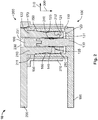
- FIG. 1 shows a schematic sectional side view of a plug connector system 10.
- the plug connector system 10 comprises a plug connector 100 and a plug connector mating piece 200.
- the plug connector system 10 is provided to establish an electrically conductive connection between a first conductor 190 and a second conductor 290.
- the first conductor 190 and the second conductor 290 are illustrated merely schematically in Figure 1 .
- the first conductor 190 can be designed as a busbar, for example.
- the plug connector 100 is connected to the first conductor 190 in an electrically conductive manner and can be designed as a fixed plug connector, for example.
- the plug connector mating piece 200 is connected to the second conductor 290 in an electrically conductive manner an can be designed as a movable plug, for example.
- the plug connector system 10 can be provided for use in the automotive industry, for example.
- the plug connector 100 has a contact socket 110.
- the contact socket 110 comprises an electrically conductive material, for example a metal.
- the contact socket 110 of the plug connector 100 is connected to the first conductor 190 in an electrically conductive manner.
- the contact socket 110 has a receiving region 120. At an axial end face of the contact socket 110, this latter has an insertion opening 122 at which the receiving region 120 is open.
- the insertion opening 122 is orientated perpendicularly to the axial direction of the contact socket 110.
- a connecting direction 300 is orientated parallel to the axial direction of the contact socket 110 and leads from the outside through the insertion opening 122 into the receiving region 120 of the contact socket 110 of the plug connector 100.
- An inner wall of the contact socket 110 forms a wall 121 of the receiving region 120.
- An outer wall of the contact socket 110 of the plug connector 100 is covered by an outer touch protection 170.
- the outer touch protection 170 can also extend beyond the insertion opening 122 of the contact socket 110 and have a corresponding opening.
- the outer touch protection 170 comprises an electrically insulating material, for example a plastic material.
- the outer touch protection 170 is provided to prevent the electrically conductive contact socket 110 from being touched accidentally. However, the outer touch protection 170 can also be omitted.
- a substantially cylindrical holding pin 130 is arranged in the receiving region 120 of the contact socket 110.
- the holding pin 130 is arranged centrally in the receiving region 120 and orientated parallel to the axis of the contact socket 110.
- the holding pin 130 comprises an electrically conductive material and is connected to the contact socket 110 in an electrically conductive manner.
- An inner touch protection 180 is formed on an end face of the holding pin 130 which is orientated towards the insertion opening 122 of the contact socket 110.
- the inner touch protection 180 comprises an electrically insulating material, for example a plastic material.
- the inner touch protection 180 is provided to prevent the holding pin 130 and the wall 121 of the receiving region 120 of the contact socket 110 from being touched accidentally. However, the inner touch protection 180 can also be omitted.
- the contact socket 110 of the plug connector 100 has, near to the insertion opening 122, a contact chamfer 150 which is formed by a portion of the wall 121 of the receiving region 120.
- the receiving region 120 tapers in the connecting direction 300 in the region of the contact chamfer 150.
- the receiving region 120 therefore widens in the region of the contact chamfer 150, from the interior of the contact socket 110 in the direction of the insertion opening 122.
- a contact spring 160 is arranged on the wall 121 of the receiving region 120 of the contact socket 110 of the plug connector 100.
- the contact spring 160 comprises an electrically conductive material, for example a metal.
- the contact spring 160 can comprise copper, for example.
- the contact spring 160 can be fastened, for example, in a groove 125 formed in the wall 121 of the receiving region 120. In this case, the contact spring 160 projects from the wall 121 of the receiving region 120 into the interior of the receiving region 120 in a direction contrary to the radial direction 310.
- the contact spring 160 is resiliently deformable.
- a locking spring 140 is arranged on a lateral surface 131 of the holding pin 130.
- the locking spring 140 surrounds the holding pin 130 in the form of a sleeve.
- the locking spring 140 can be arranged in a groove 135 formed on the lateral surface 131 of the holding pin 130.
- the locking spring 140 projects from the lateral surface 131 of the holding pin 130 into the receiving region 120 contrary to the radial direction 310.
- the locking spring 140 is elastically deformable.
- the locking spring 140 can be formed from steel, for example.
- the plug connector mating piece 200 of the plug connector system 10 has a contact pin 210.
- the contact pin 210 comprises an electrically conductive material and is connected to the second conductor 290 in an electrically conductive manner. It is expedient if the contact pin 210 comprises a metal.
- the contact pin 210 of the plug connector mating piece 200 is provided to be inserted into the receiving region 120 of the contact socket 110 of the plug connector 100 in the connecting direction 300.
- the plug connector mating piece 200 is orientated such that a longitudinal axis of the contact pin 210 is orientated parallel to the connecting direction 300.
- An end face 212 of the contact pin 210 of the plug connector mating piece 200 is then orientated perpendicularly to the connecting direction 300 and faces the insertion opening 122 of the contact socket 110 of the plug connector 100.
- a mating contact chamfer 250 is formed on a lateral surface 211 of the contact pin 210 of the plug connector mating piece 200.
- the contact pin 210 tapers in the connecting direction 300 in the region of the mating contact chamfer, which means that a diameter, measured in the radial direction 310, of the contact pin 210 decreases in the connecting direction 300.
- a pin receiving opening 230 is formed on the end face 212 of the contact pin 210 of the plug connector mating piece 200, which pin receiving opening 230 extends into the contact pin 210 contrary to the connecting direction 300.
- the pin receiving opening 230 is provided to receive the holding pin 130 of the plug connector 100.
- a pressure chamfer 240 is formed on a wall 231 of the pin receiving opening 230.
- the pin receiving opening 230 tapers in the connecting direction 300 in the region of the pressure chamfer 240.
- the diameter, measured in the radial direction 310, of the pin receiving opening 230 therefore decreases in the connecting direction 300 in the region of the pressure chamfer 240.
- the plug connector mating piece 200 has an outer touch protection 270, which surrounds the contact pin 210 in the form of a sleeve and is provided to prevent the contact pin 210 from being touched accidentally.
- the outer touch protection 270 is designed such that the outer touch protection 270 of the plug connector mating piece 200 surrounds the outer touch protection 170 of the plug connector 100 when the plug connector mating piece 200 is plugged together with the plug connector 100.
- the outer touch protection 270 comprises an electrically insulating material, for example a plastic material.
- the outer touch protection 270 can be omitted in a simplified variant of the plug connector mating piece 200.
- the plug connector mating piece 200 additionally has an inner touch protection 280, which is arranged on the end face 212 of the contact pin 210 and has an opening which is coaxial to the pin receiving opening 230.
- the inner touch protection 280 is provided to prevent the contact pin 210 from being touched accidentally.
- the inner touch protection 280 comprises an electrically insulating material, for example a plastic material.
- the inner touch protection 280 can also be omitted in a simplified version.
- the plug connector mating piece 200 of the plug connector system 10 can be plugged together with the plug connector 100 of the plug connector system 10 in that the contact pin 210 of the plug connector mating piece 200 is inserted into the receiving region 120 of the plug connector 100 in the connecting direction 300. In this case, the holding pin 130 of the plug connector 100 is received in the pin receiving opening 230 of the contact pin 210 of the plug connector mating piece 200.
- Figure 2 shows a schematic sectional side view of the plug connector 100 and the plug connector mating piece 200 of the plug connector system 10 in the fully plugged together state.
- the holding pin 130 of the plug connector 100 has been received in the pin receiving opening 230 of the contact pin 210 of the plug connector mating piece 200.
- the locking spring 140 arranged on the holding pin 130 has been elastically deformed and lies against the pressure chamfer 240 of the wall 231 of the pin receiving opening 230 of the contact pin 210.
- a force, acting in the connecting direction 300 is exerted on the contact pin 210 of the plug connector mating piece 200 by the locking spring 140 lying against the pressure chamfer 240. Therefore, as a result of the force exerted on the pressure chamfer 240 by the locking spring 140, the contact pin 210 of the plug connector mating piece 200 is drawn into the receiving region 120 of the contact socket 110 of the plug connector 100 in the connecting direction 300 and held in the contact socket 110 of the plug connector 100.
- the locking spring 140 can also establish an electrically conductive connection between the holding pin 130 of the plug connector 100 and the contact pin 210 of the plug connector mating piece 200.
- the contact spring 160 of the plug connector 100 which is arranged in the receiving region 120 on the wall 121 of the receiving region 120, has been elastically deformed as a result of the insertion of the contact pin 210 of the plug connector mating piece 200 and now presses against the lateral surface 211 of the contact pin 210 contrary to the radial direction 310.
- the contact spring 160 thus establishes an electrically conductive connection between the contact socket 110 of the plug connector 100 and the contact pin 210 of the plug connector mating piece 200.
- the mating contact chamfer 250 of the contact pin 210 of the plug connector mating piece 200 which is fully plugged together with the plug connector 100 is in contact with the contact chamfer 150 of the contact socket 110 of the plug connector 100.
- the mating contact chamfer 250 of the plug connector mating piece 200 is pressed against the contact chamfer 150 of the plug connector 100 as a result of the force exerted on the pressure chamfer 240 of the plug connector mating piece 200 by the locking spring 140 of the plug connector 100.
- a reliable electrical contact is thus formed between the contact chamfer 150 of the plug connector 100 and the mating contact chamfer 250.
- the contact spring 160 of the plug connector 100 can be omitted in a simplified embodiment of the plug connector system 10.
- an electrically conductive connection between the plug connector 100 and the plug connector mating piece 200 is established merely by the contact between the contact chamfer 150 of the plug connector 100 and the mating contact chamfer 250 of the plug connector mating piece 200 and possibly by the contact between the locking spring 140 of the plug connector 100 and the pressure chamfer 240 of the plug connector mating piece 200.
- FIG 3 shows a schematic sectional side view of a plug connector system 20.
- the plug connector system 20 has many similarities to the plug connector system 10 described above with reference to Figures 1 and 2 . Components of the plug connector system 20 which correspond to components present in the plug connector system 10 are not described in detail again below. In this regard, the description above of the plug connector system 10 also applies to the plug connector system 20.
- the plug connector system 20 comprises a plug connector 1100 which corresponds to the plug connector 100 of the plug connector system 10 and is connected to a first conductor 1190 in an electrically conductive manner, which first conductor corresponds to the first conductor 190 of Figures 1 and 2 .
- the plug connector system 20 moreover comprises a plug connector mating piece 1200 which corresponds to the plug connector mating piece 200 of the plug connector system 10 and is connected to a second conductor 1290 in an electrically conductive manner, which second conductor corresponds to the second conductor 290 of Figures 1 and 2 .
- Figure 3 shows the plug connector 1100 and the plug connector mating piece 1200 of the plug connector system 20 in a fully plugged together state in which the plug connector 1100 and the plug connector mating piece 1200 establish an electrically conductive connection between the first conductor 1190 and the second conductor 1290.
- the plug connector 1100 has a contact socket 1110 with a receiving region 1120 which, apart from the differences described below, correspond to the contact socket 110 and the receiving region 120 of the plug connector 100 of the plug connector system 10.
- the plug connector mating piece 1200 has a contact pin 1210 with an end face 1212 which, apart from the differences described below, corresponds to the contact pin 210 of the plug connector mating piece 200 of the plug connector system 10.
- the contact pin 1210 of the plug connector mating piece 1200 can be inserted into the receiving region 1120 in a connecting direction 1300 through an insertion opening 1122 of the contact socket 1110.
- a holding pin 1130 is arranged in the receiving region 1120 of the contact socket 1110, which holding pin, apart from the differences described below, corresponds to the holding pin 130 of the plug connector 100.
- the contact pin 1210 of the plug connector mating piece 1200 has a pin receiving opening 1230, which is provided to receive the holding pin 1130.
- the pin receiving opening 1230 of the plug connector mating piece 1200 corresponds to the pin receiving opening 230 of the plug connector mating piece 200, although it does not have a pressure chamfer.
- the plug connector 1100 has an outer touch protection 1170 and an inner touch protection 1180, which are designed in the same manner as the outer touch protection 170 and the inner touch protection 180 of the plug connector 100.
- the plug connector mating piece 1200 has an outer touch protection 1270 and an inner touch protection 1280, which are designed in the same manner as the outer touch protection 270 and the inner touch protection 280 of the plug connector mating piece 200 of the plug connector system 10.
- the outer touch protection 1170 and the inner touch protection 1180 of the plug connector 1100 and the outer touch protection 1270 and the inner touch protection 1280 of the plug connector mating piece 1200 can in turn be omitted in all cases or in some cases.
- the holding pin 1130 of the plug connector 1100 of the plug connector system 20 is formed entirely from an electrically insulating material.
- a separate inner touch protection 1280 is then not required, but is instead formed by a portion of the holding pin 1130.
- the plug connector 1100 of the plug connector system 20 has a contact chamfer 1150, which is designed in the same manner as the contact chamfer 150 of the plug connector 100 of the plug connector system 10.
- the plug connector mating piece 1200 has a mating contact chamfer 1250, which is designed in the same manner as the mating contact chamfer 250 of the plug connector mating piece 200.
- the contact chamfer 1150 of the plug connector 1100 is in turn pressed against the mating contact chamfer 1250 of the plug connector mating piece 1200 when the plug connector 1100 and the plug connector mating piece 1200 are fully plugged together.
- the plug connector 1100 of the plug connector system 20 has neither a contact spring nor a groove provided to receive the contact spring.
- a groove 1125 is arranged in a wall 1121 of the receiving region 1120, in which groove a locking spring 1140 is arranged.
- the locking spring 1140 can be designed as an annular spring or as an annular helical spring, for example.
- a pressure chamfer 1240 is formed on a lateral surface 1211 of the contact pin 1210.
- the pressure chamfer 1240 is formed such that the contact pin 1210 widens in the connecting direction 1300 in the region of the pressure chamfer 1240. This means that a diameter, measured in the radial direction 1310, of the contact pin 1210 increases in the connecting direction 1300 in the region of the pressure chamfer 1240.
- the locking spring 1140 of the plug connector 1100 exerts a force on the pressure chamfer 1240 of the plug connector mating piece 1200, which, as a result of the orientation of the pressure chamfer 1240, produces a force, acting in the connecting direction 1300, on the contact pin 1210 of the plug connector mating piece 1200.
- the plug connector mating piece 1200 is thus held firmly on the plug connector 1100.
- the mating contact chamfer 1250 of the plug connector mating piece 1200 is thus pressed firmly against the contact chamfer 1150 of the plug connector 1100.
- the locking spring 1140 can also establish an electrically conductive connection between the contact socket 1110 of the plug connector 1100 and the contact pin 1210 of the plug connector mating piece 1200.
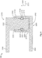
- FIG 4 shows a schematic sectional side view of a plug connector system 30.
- the plug connector system 30 has many similarities to the plug connector system 10 of Figures 1 and 2 and the plug connector system 20 of Figure 3 . Apart from the differences described below, the description above of the plug connector system 10 and the plug connector system 20 also applies to the plug connector system 30 of Figure 4 .
- the plug connector system 30 comprises a plug connector 2100 and a plug connector mating piece 2200.
- the plug connector 2100 is connected to a first conductor 2190.
- the plug connector mating piece 2200 is connected to a second conductor 2290.
- the plug connector system 30 is provided to establish an electrically conductive connection between the first conductor 2190 and the second conductor 2290 when the plug connector 2100 and the plug connector mating piece 2200 are fully plugged together, as illustrated in Figure 4 .
- the plug connector mating piece 2200 of the plug connector system 30 has a contact socket 2210 with a receiving region 2220.
- the plug connector mating piece 2200 of the plug connector system 30 therefore has similarities to the plug connector 100 of the plug connector system 10.
- the plug connector 2100 of the plug connector system 30 has a contact pin 2110.
- the plug connector 2100 therefore has similarities to the plug connector mating piece 200 of the plug connector system 10.
- Leading with an end face 2112, the contact pin 2110 of the plug connector 2100 can be inserted into the receiving region 2220 of the contact socket 2210 of the plug connector mating piece 2200 contrary to a connecting direction 2300 through an insertion opening 2222 of the receiving region 2220.
- the plug connector 2100 also has a locking spring 2140.
- the locking spring 2140 is arranged on a lateral surface 2111 of the contact pin 2110.
- the lateral surface 2111 of the contact pin 2110 can have a circumferential groove 2115 in which the locking spring 2140 is held.
- the locking spring 2140 can be designed in the same manner as the locking spring 1140 of the plug connector 1100 of the plug connector system 20.
- a pressure chamfer 2240 is formed on a wall 2221 of the receiving region 2220.
- the receiving region 2220 tapers in the connecting direction 2300 in the region of the pressure chamfer 2240. This means that a diameter, measured in a radial direction 2310, of the receiving region 2220 of the contact socket 2210 of the plug connector mating piece 2200 decreases in the connecting direction 2300 in the region of the pressure chamfer 2240.
- the contact pin 2110 of the plug connector 2100 has a contact chamfer 2150 on its lateral surface 2111, which contact chamfer is designed such that the contact pin 2110 widens in the connecting direction 2300 in the region of the contact chamfer 2150. Therefore, a diameter, measured in the radial direction 2310, of the contact pin 2110 increases in the connecting direction 2300 in the region of the contact chamfer 2150.
- the contact socket 2210 of the plug connector mating piece 2200 has a mating contact chamfer 2250 at which the receiving region 2220 widens in the connecting direction 2300.
- the mating contact chamfer 2250 is formed by a portion of the wall 2221 of the receiving region 2220 near to the insertion opening 2222.
- a diameter, measured in the radial direction 2310, of the receiving region 2220 increases in the connecting direction 2300 in the region of the mating contact chamfer 2250.
- the locking spring 2140 of the plug connector 2100 exerts a force on the pressure chamfer 2240 of the plug connector mating piece, which results in a force, acting in the connecting direction 2300, on the plug connector mating piece 2200 owing to the orientation of the pressure chamfer 2240.
- the plug connector 2100 and the plug connector mating piece 2200 are thus pressed firmly together.
- the contact chamfer 2150 of the plug connector 2100 lies against the mating contact chamfer 2250 of the plug connector mating piece 2200.
- the force exerted on the plug connector mating piece 2200 by the locking spring 2140 of the plug connector 2100 presses the contact chamfer 2150 against the mating contact chamfer 2250.
- the contact between the locking spring 2140 of the plug connector 2100 and the pressure chamfer 2240 of the plug connector mating piece 2200 can establish a further electrical contact between the contact pin 2110 of the plug connector 2100 and the contact socket 2210 of the plug connector mating piece 2200.
- neither the plug connector 2100 nor the plug connector mating piece 2200 of the plug connector system 30 has a respective touch protection. It is, however, possible to design the plug connector 2100 with a touch protection which corresponds to that of the plug connector mating piece 200 of the plug connector system 10. Accordingly, the plug connector mating piece 2200 of the plug connector system 30 can be equipped with a touch protection which corresponds to that of the plug connector 100 of the plug connector system 10.
- a contact spring can be additionally provided in each case, which contact spring is designed in the same manner as the contact spring 160 of the plug connector 100 of the plug connector system 10.
- this can be arranged in the receiving region 1120 of the plug connector 1100.
- this can be arranged in the receiving region 2220 of the plug connector mating piece 2200.
- the plug connector system 30 of Figure 4 can be additionally equipped with a holding pin. This can be designed in the same manner as the holding pin 1130 of the plug connector 1100 of the plug connector system 20, although it is arranged in the receiving region 2220 of the contact socket 2210 of the plug connector mating piece 2200.
- the contact pin 2110 of the plug connector 2100 has a pin receiving opening which corresponds to the pin receiving opening 1230 of the plug connector mating piece 1200 of the plug connector system 20.
Landscapes
- Details Of Connecting Devices For Male And Female Coupling (AREA)
- Coupling Device And Connection With Printed Circuit (AREA)
Abstract
Description
- The present invention relates to a plug connector, a plug connector mating piece and a plug connector system.
- Plug connector systems are known in many variants from the prior art.
- One object of the present invention consists in providing a plug connector. A further object of the present invention consists in providing a plug connector mating piece. A further object of the present invention consists in providing a plug connector system. These objects are achieved by a plug connector, a plug connector mating piece and a plug connector system with the features of the independent claims. Various developments are revealed in the dependent claims.
- A plug connector is designed such that a plug connector mating piece can be plugged together with the plug connector in a connecting direction. In this case, the plug connector has a locking spring, which is provided to exert a force, acting in the connecting direction, on a plug connector mating piece when this is fully plugged together with the plug connector.
- The locking spring of this plug connector advantageously brings about a pressing of a plug connector mating piece against the plug connector in the connecting direction, whereby reliable electrical contact between the plug connector and the plug connector mating piece is ensured. As a result, the vibration resistance of the plug connector can also be increased. In this case, the pressing function is advantageously fulfilled by the locking spring of the plug connector so that it is not necessary to realize a pressing action by means of a plastic housing of the plug connector, for example. A reduction in the pressing force due to material fatigue can thus be prevented. The locking spring of this plug connector can also provide an additional electrical contact point between the plug connector and a plug connector mating piece.
- In one embodiment of the plug connector, this has a contact socket with a receiving region which is designed such that a contact pin of a plug connector mating piece can be inserted into the receiving region in the connecting direction. In this case, the locking spring is arranged in the receiving region. This plug connector advantageously enables particularly simple connection to a plug connector mating piece in that a contact pin of the plug connector mating piece is inserted into the receiving region of the contact socket. Arranging the locking spring in the receiving region protects it from damage.
- In one embodiment of the plug connector, the contact socket has a contact chamfer at which the receiving region tapers in the connecting direction. This contact chamfer of the contact socket of the plug connector can advantageously serve to establish an electrically conductive connection with a plug connector mating piece. As a result of the receiving region tapering in the connecting direction at the contact chamfer, the force produced by the locking spring of the plug connector in the connecting direction brings about a pressing of a plug connector mating piece against the contact chamfer of the plug connector, whereby a reliable electrically conductive connection is ensured.
- In one embodiment of the plug connector, a holding pin is arranged in the receiving region. This holding pin can advantageously prevent an inner region of the contact socket from being touched accidently. The holding pin can also serve as a centring aid when connecting the plug connector to a matching plug connector mating piece.
- In one embodiment of the plug connector, the locking spring is arranged on the holding pin and surrounds the holding pin in the form of a sleeve. This advantageously enables a compact construction of the plug connector and enables further components to be provided in the remaining portions of the receiving region of the contact socket.
- In one embodiment of the plug connector, a contact spring is arranged in the receiving region, which contact spring is provided to establish an electrically conductive connection between the contact socket and a contact pin of a plug connector mating piece, which contact pin is inserted into the receiving region. This contact spring can advantageously establish a reliable electrically conductive connection between the contact socket of the plug connector and a contact pin of a suitable plug connector mating piece.
- In one embodiment of the plug connector, the contact spring is arranged on a wall of the receiving region. This arrangement of the contact spring advantageously ensures reliable contacting of a contact pin of a plug connector mating piece, which contact pin is inserted into the receiving region. To this end, the contact spring can exert a contact force, acting contrary to a radial direction, on the contact pin.
- In one embodiment of the plug connector, this has a contact pin which is provided to be inserted into a receiving region of a contact socket of a plug connector mating piece contrary to the connecting direction. In this case, the locking spring is arranged on the contact pin. This configuration of the plug connector advantageously enables a simple and reliable plugging together of the plug connector and a matching plug connector mating piece.
- In one embodiment of the plug connector, the contact pin has a contact chamfer at which the contact pin widens in the connecting direction. This contact chamfer can serve to establish an electrically conductive connection between the contact pin of the plug connector and a matching plug connector mating piece. The force exerted by the locking spring of the plug connector on the plug connector mating piece in the connecting direction brings about a pressing of the plug connector mating piece against the contact chamfer, whereby a reliable electrically conductive connection between the plug connector and the plug connector mating piece is ensured.
- A plug connector mating piece is designed to be plugged together with a plug connector in a connecting direction, In this case, the plug connector mating piece has a pressure chamfer which is designed such that a locking spring of a plug connector which is fully plugged together with the plug connector mating piece can exert a force, acting in the connecting direction, on the pressure chamfer.
- This plug connector mating piece can advantageously have a good vibration resistance, i.e. it can also provide a reliable electrical connection with a matching plug connector under the influence of vibrations. As a result of a force acting on the pressure chamfer of this plug connector mating piece, the plug connector mating piece is securely held on a matching plug connector. In this case, this pressing force does not have to be provided by a housing component or another plastic component of the plug connector mating piece, whereby the risk of the contact security decreasing due to the effects of material fatigue is reduced.
- In one embodiment of the plug connector mating piece, this has a contact pin which is provided to be inserted into a receiving recess of a contact socket of a plug connector in the connecting direction. In this case, the contact pin has the pressure chamfer. This configuration of the plug connector mating piece advantageously enables simple connection of the plug connector mating piece to a suitable plug connector. As a result of the pressure chamfer being arranged on the contact pin of the plug connector mating piece, the pressure chamfer can provide an electrically conductive contact point between the plug connector mating piece and a suitable plug connector.
- In one embodiment of the plug connector mating piece, the contact pin has a mating contact chamfer at which the contact pin tapers in the connecting direction. The mating contact chamfer of the contact pin of this plug connector mating piece can be provided to establish an electrically conductive connection with a suitable plug connector. As a result of the contact pin tapering in the connecting direction at the mating contact chamfer, the mating contact chamfer is pressed against a suitable plug connector when a force, acting in the connecting direction, is exerted on the plug connector mating piece. This can advantageously ensure a reliable electrically conductive connection.
- In one embodiment of the plug connector mating piece, the contact pin has a pin receiving opening. This pin receiving opening can be provided, for example, to receive a holding pin of a matching plug connector. The pin receiving opening and a holding pin of a matching plug connector can advantageously serve as a centring aid when plugging together the plug connector mating piece and the plug connector.
- In one embodiment of the plug connector mating piece, the pressure chamfer is arranged on a wall of the pin receiving opening. In this case, the pin receiving opening tapers in the connecting direction in the region of the pressure chamfer. This advantageously represents a simple and compact configuration of the plug connector mating piece.
- In one embodiment of the plug connector mating piece, the pressure chamfer is arranged on an outer lateral surface of the contact pin. In this case, the contact pin widens in the connecting direction in the region of the pressure chamfer. This also advantageously enables a simple and compact configuration of the plug connector mating piece.
- In one embodiment of the plug connector mating piece, this has a contact socket with a receiving region which is designed such that a contact pin of a plug connector can be inserted into the receiving region contrary to the connecting direction. In this case, the contact socket has the pressure chamfer. This configuration of the plug connector mating piece advantageously enables a simple plugging together of the plug connector mating piece and a suitable plug connector.
- In one embodiment of the plug connector mating piece, the contact socket has a mating contact chamfer at which the receiving region widens in the connecting direction. The mating contact chamfer can serve to form an electrically conductive connection with a suitable plug connector. As a result of the receiving region of the contact socket of this plug connector mating piece widening in the connecting direction in the region of the mating contact chamfer, the mating contact chamfer is pressed against a suitable plug connector when a force, acting in the connecting direction, is exerted on the pressure chamfer of the plug connector mating piece. This can advantageously establish a robust and more vibration-resistant electrically conductive connection.
- A plug connector system comprises a plug connector of the type mentioned above and a plug connector mating piece of the type mentioned above. In this case, the locking spring of the plug connector exerts a force, acting in the connecting direction, on the plug connector mating piece via the pressure chamfer when the plug connector and the plug connector mating piece are fully plugged together. This plug connector system advantageously enables a reliable and vibration-resistant electrically conductive connection to be established between the plug connector and the plug connector mating piece.
- In one embodiment of the plug connector system, the plug connector and the plug connector mating piece are designed with a contact chamfer and a mating contact chamfer. In this case, the contact chamfer of the plug connector is pressed against the mating contact chamfer of the plug connector mating piece when the plug connector and the plug connector mating piece are fully plugged together. This advantageously establishes a robust and vibration-resistant electrically conductive connection between the contact chamfer of the plug connector and the mating contact chamfer of the plug connector mating piece.
- The properties, features and advantageous of this invention, which are described above, will be explained in more detail below with reference to the accompanying figures. In a schematic illustration in each case:
- Figure 1
- shows a plug connector system with a plug connector and a plug connector mating piece in an unconnected state;
- Figure 2
- shows the plug connector and the plug connector mating piece of the plug connector system in a connected state;
- Figure 3
- shows a further plug connector system; and
- Figure 4
- shows another further plug connector system.
-
Figure 1 shows a schematic sectional side view of aplug connector system 10. Theplug connector system 10 comprises aplug connector 100 and a plugconnector mating piece 200. - The
plug connector system 10 is provided to establish an electrically conductive connection between afirst conductor 190 and asecond conductor 290. Thefirst conductor 190 and thesecond conductor 290 are illustrated merely schematically inFigure 1 . Thefirst conductor 190 can be designed as a busbar, for example. - The
plug connector 100 is connected to thefirst conductor 190 in an electrically conductive manner and can be designed as a fixed plug connector, for example. The plugconnector mating piece 200 is connected to thesecond conductor 290 in an electrically conductive manner an can be designed as a movable plug, for example. - The
plug connector system 10 can be provided for use in the automotive industry, for example. - The
plug connector 100 has acontact socket 110. Thecontact socket 110 comprises an electrically conductive material, for example a metal. Thecontact socket 110 of theplug connector 100 is connected to thefirst conductor 190 in an electrically conductive manner. - The
contact socket 110 has a receivingregion 120. At an axial end face of thecontact socket 110, this latter has aninsertion opening 122 at which the receivingregion 120 is open. Theinsertion opening 122 is orientated perpendicularly to the axial direction of thecontact socket 110. A connectingdirection 300 is orientated parallel to the axial direction of thecontact socket 110 and leads from the outside through theinsertion opening 122 into the receivingregion 120 of thecontact socket 110 of theplug connector 100. An inner wall of thecontact socket 110 forms awall 121 of the receivingregion 120. - An outer wall of the
contact socket 110 of theplug connector 100 is covered by anouter touch protection 170. Theouter touch protection 170 can also extend beyond theinsertion opening 122 of thecontact socket 110 and have a corresponding opening. Theouter touch protection 170 comprises an electrically insulating material, for example a plastic material. Theouter touch protection 170 is provided to prevent the electricallyconductive contact socket 110 from being touched accidentally. However, theouter touch protection 170 can also be omitted. - A substantially
cylindrical holding pin 130 is arranged in the receivingregion 120 of thecontact socket 110. The holdingpin 130 is arranged centrally in the receivingregion 120 and orientated parallel to the axis of thecontact socket 110. - It is expedient if the holding
pin 130 comprises an electrically conductive material and is connected to thecontact socket 110 in an electrically conductive manner. However, it is also possible to form the holdingpin 130 from an electrically insulating material. - An
inner touch protection 180 is formed on an end face of the holdingpin 130 which is orientated towards theinsertion opening 122 of thecontact socket 110. Theinner touch protection 180 comprises an electrically insulating material, for example a plastic material. Theinner touch protection 180 is provided to prevent theholding pin 130 and thewall 121 of the receivingregion 120 of thecontact socket 110 from being touched accidentally. However, theinner touch protection 180 can also be omitted. - The
contact socket 110 of theplug connector 100 has, near to theinsertion opening 122, acontact chamfer 150 which is formed by a portion of thewall 121 of the receivingregion 120. The receivingregion 120 tapers in the connectingdirection 300 in the region of thecontact chamfer 150. The receivingregion 120 therefore widens in the region of thecontact chamfer 150, from the interior of thecontact socket 110 in the direction of theinsertion opening 122. - A
contact spring 160 is arranged on thewall 121 of the receivingregion 120 of thecontact socket 110 of theplug connector 100. Thecontact spring 160 comprises an electrically conductive material, for example a metal. Thecontact spring 160 can comprise copper, for example. Thecontact spring 160 can be fastened, for example, in agroove 125 formed in thewall 121 of the receivingregion 120. In this case, thecontact spring 160 projects from thewall 121 of the receivingregion 120 into the interior of the receivingregion 120 in a direction contrary to theradial direction 310. Thecontact spring 160 is resiliently deformable. - A locking
spring 140 is arranged on alateral surface 131 of the holdingpin 130. The lockingspring 140 surrounds the holdingpin 130 in the form of a sleeve. The lockingspring 140 can be arranged in agroove 135 formed on thelateral surface 131 of the holdingpin 130. The lockingspring 140 projects from thelateral surface 131 of the holdingpin 130 into the receivingregion 120 contrary to theradial direction 310. In this case, the lockingspring 140 is elastically deformable. The lockingspring 140 can be formed from steel, for example. - The plug
connector mating piece 200 of theplug connector system 10 has acontact pin 210. Thecontact pin 210 comprises an electrically conductive material and is connected to thesecond conductor 290 in an electrically conductive manner. It is expedient if thecontact pin 210 comprises a metal. - The
contact pin 210 of the plugconnector mating piece 200 is provided to be inserted into the receivingregion 120 of thecontact socket 110 of theplug connector 100 in the connectingdirection 300. To this end, the plugconnector mating piece 200 is orientated such that a longitudinal axis of thecontact pin 210 is orientated parallel to the connectingdirection 300. Anend face 212 of thecontact pin 210 of the plugconnector mating piece 200 is then orientated perpendicularly to the connectingdirection 300 and faces theinsertion opening 122 of thecontact socket 110 of theplug connector 100. - A
mating contact chamfer 250 is formed on alateral surface 211 of thecontact pin 210 of the plugconnector mating piece 200. Thecontact pin 210 tapers in the connectingdirection 300 in the region of the mating contact chamfer, which means that a diameter, measured in theradial direction 310, of thecontact pin 210 decreases in the connectingdirection 300. - A
pin receiving opening 230 is formed on theend face 212 of thecontact pin 210 of the plugconnector mating piece 200, whichpin receiving opening 230 extends into thecontact pin 210 contrary to the connectingdirection 300. Thepin receiving opening 230 is provided to receive the holdingpin 130 of theplug connector 100. - A
pressure chamfer 240 is formed on awall 231 of thepin receiving opening 230. In this case, thepin receiving opening 230 tapers in the connectingdirection 300 in the region of thepressure chamfer 240. The diameter, measured in theradial direction 310, of thepin receiving opening 230 therefore decreases in the connectingdirection 300 in the region of thepressure chamfer 240. - The plug
connector mating piece 200 has anouter touch protection 270, which surrounds thecontact pin 210 in the form of a sleeve and is provided to prevent thecontact pin 210 from being touched accidentally. Theouter touch protection 270 is designed such that theouter touch protection 270 of the plugconnector mating piece 200 surrounds theouter touch protection 170 of theplug connector 100 when the plugconnector mating piece 200 is plugged together with theplug connector 100. Theouter touch protection 270 comprises an electrically insulating material, for example a plastic material. Theouter touch protection 270 can be omitted in a simplified variant of the plugconnector mating piece 200. - The plug
connector mating piece 200 additionally has aninner touch protection 280, which is arranged on theend face 212 of thecontact pin 210 and has an opening which is coaxial to thepin receiving opening 230. Theinner touch protection 280 is provided to prevent thecontact pin 210 from being touched accidentally. Theinner touch protection 280 comprises an electrically insulating material, for example a plastic material. Theinner touch protection 280 can also be omitted in a simplified version. - The plug
connector mating piece 200 of theplug connector system 10 can be plugged together with theplug connector 100 of theplug connector system 10 in that thecontact pin 210 of the plugconnector mating piece 200 is inserted into the receivingregion 120 of theplug connector 100 in the connectingdirection 300. In this case, the holdingpin 130 of theplug connector 100 is received in thepin receiving opening 230 of thecontact pin 210 of the plugconnector mating piece 200. -
Figure 2 shows a schematic sectional side view of theplug connector 100 and the plugconnector mating piece 200 of theplug connector system 10 in the fully plugged together state. - The holding
pin 130 of theplug connector 100 has been received in thepin receiving opening 230 of thecontact pin 210 of the plugconnector mating piece 200. - The locking
spring 140 arranged on the holdingpin 130 has been elastically deformed and lies against thepressure chamfer 240 of thewall 231 of thepin receiving opening 230 of thecontact pin 210. As a result of the orientation of thepressure chamfer 240, a force, acting in the connectingdirection 300, is exerted on thecontact pin 210 of the plugconnector mating piece 200 by the lockingspring 140 lying against thepressure chamfer 240. Therefore, as a result of the force exerted on thepressure chamfer 240 by the lockingspring 140, thecontact pin 210 of the plugconnector mating piece 200 is drawn into the receivingregion 120 of thecontact socket 110 of theplug connector 100 in the connectingdirection 300 and held in thecontact socket 110 of theplug connector 100. In addition, the lockingspring 140 can also establish an electrically conductive connection between the holdingpin 130 of theplug connector 100 and thecontact pin 210 of the plugconnector mating piece 200. - The
contact spring 160 of theplug connector 100, which is arranged in the receivingregion 120 on thewall 121 of the receivingregion 120, has been elastically deformed as a result of the insertion of thecontact pin 210 of the plugconnector mating piece 200 and now presses against thelateral surface 211 of thecontact pin 210 contrary to theradial direction 310. Thecontact spring 160 thus establishes an electrically conductive connection between thecontact socket 110 of theplug connector 100 and thecontact pin 210 of the plugconnector mating piece 200. - The
mating contact chamfer 250 of thecontact pin 210 of the plugconnector mating piece 200 which is fully plugged together with theplug connector 100 is in contact with thecontact chamfer 150 of thecontact socket 110 of theplug connector 100. Themating contact chamfer 250 of the plugconnector mating piece 200 is pressed against thecontact chamfer 150 of theplug connector 100 as a result of the force exerted on thepressure chamfer 240 of the plugconnector mating piece 200 by the lockingspring 140 of theplug connector 100. A reliable electrical contact is thus formed between thecontact chamfer 150 of theplug connector 100 and themating contact chamfer 250. - The
contact spring 160 of theplug connector 100 can be omitted in a simplified embodiment of theplug connector system 10. In this case, an electrically conductive connection between theplug connector 100 and the plugconnector mating piece 200 is established merely by the contact between thecontact chamfer 150 of theplug connector 100 and themating contact chamfer 250 of the plugconnector mating piece 200 and possibly by the contact between the lockingspring 140 of theplug connector 100 and thepressure chamfer 240 of the plugconnector mating piece 200. -
Figure 3 shows a schematic sectional side view of aplug connector system 20. Theplug connector system 20 has many similarities to theplug connector system 10 described above with reference toFigures 1 and2 . Components of theplug connector system 20 which correspond to components present in theplug connector system 10 are not described in detail again below. In this regard, the description above of theplug connector system 10 also applies to theplug connector system 20. - The
plug connector system 20 comprises aplug connector 1100 which corresponds to theplug connector 100 of theplug connector system 10 and is connected to afirst conductor 1190 in an electrically conductive manner, which first conductor corresponds to thefirst conductor 190 ofFigures 1 and2 . Theplug connector system 20 moreover comprises a plugconnector mating piece 1200 which corresponds to the plugconnector mating piece 200 of theplug connector system 10 and is connected to asecond conductor 1290 in an electrically conductive manner, which second conductor corresponds to thesecond conductor 290 ofFigures 1 and2 .Figure 3 shows theplug connector 1100 and the plugconnector mating piece 1200 of theplug connector system 20 in a fully plugged together state in which theplug connector 1100 and the plugconnector mating piece 1200 establish an electrically conductive connection between thefirst conductor 1190 and thesecond conductor 1290. - The
plug connector 1100 has acontact socket 1110 with a receivingregion 1120 which, apart from the differences described below, correspond to thecontact socket 110 and the receivingregion 120 of theplug connector 100 of theplug connector system 10. The plugconnector mating piece 1200 has acontact pin 1210 with anend face 1212 which, apart from the differences described below, corresponds to thecontact pin 210 of the plugconnector mating piece 200 of theplug connector system 10. Thecontact pin 1210 of the plugconnector mating piece 1200 can be inserted into the receivingregion 1120 in a connectingdirection 1300 through aninsertion opening 1122 of thecontact socket 1110. - A holding
pin 1130 is arranged in the receivingregion 1120 of thecontact socket 1110, which holding pin, apart from the differences described below, corresponds to the holdingpin 130 of theplug connector 100. Thecontact pin 1210 of the plugconnector mating piece 1200 has apin receiving opening 1230, which is provided to receive theholding pin 1130. Thepin receiving opening 1230 of the plugconnector mating piece 1200 corresponds to thepin receiving opening 230 of the plugconnector mating piece 200, although it does not have a pressure chamfer. - The
plug connector 1100 has anouter touch protection 1170 and aninner touch protection 1180, which are designed in the same manner as theouter touch protection 170 and theinner touch protection 180 of theplug connector 100. The plugconnector mating piece 1200 has anouter touch protection 1270 and aninner touch protection 1280, which are designed in the same manner as theouter touch protection 270 and theinner touch protection 280 of the plugconnector mating piece 200 of theplug connector system 10. Theouter touch protection 1170 and theinner touch protection 1180 of theplug connector 1100 and theouter touch protection 1270 and theinner touch protection 1280 of the plugconnector mating piece 1200 can in turn be omitted in all cases or in some cases. - It is possible to form the
holding pin 1130 of theplug connector 1100 of theplug connector system 20 entirely from an electrically insulating material. A separateinner touch protection 1280 is then not required, but is instead formed by a portion of theholding pin 1130. - The
plug connector 1100 of theplug connector system 20 has acontact chamfer 1150, which is designed in the same manner as thecontact chamfer 150 of theplug connector 100 of theplug connector system 10. The plugconnector mating piece 1200 has amating contact chamfer 1250, which is designed in the same manner as themating contact chamfer 250 of the plugconnector mating piece 200. Thecontact chamfer 1150 of theplug connector 1100 is in turn pressed against themating contact chamfer 1250 of the plugconnector mating piece 1200 when theplug connector 1100 and the plugconnector mating piece 1200 are fully plugged together. - The
plug connector 1100 of theplug connector system 20 has neither a contact spring nor a groove provided to receive the contact spring. - Instead, in the
plug connector 1100, agroove 1125 is arranged in awall 1121 of the receivingregion 1120, in which groove alocking spring 1140 is arranged. Thelocking spring 1140 can be designed as an annular spring or as an annular helical spring, for example. - In the plug
connector mating piece 1200 of theplug connector system 20, apressure chamfer 1240 is formed on alateral surface 1211 of thecontact pin 1210. Thepressure chamfer 1240 is formed such that thecontact pin 1210 widens in the connectingdirection 1300 in the region of thepressure chamfer 1240. This means that a diameter, measured in theradial direction 1310, of thecontact pin 1210 increases in the connectingdirection 1300 in the region of thepressure chamfer 1240. - In the state of the
plug connector system 20 shown inFigure 3 in which theplug connector 1100 and the plugconnector mating piece 1200 are fully plugged together, thelocking spring 1140 of theplug connector 1100 exerts a force on thepressure chamfer 1240 of the plugconnector mating piece 1200, which, as a result of the orientation of thepressure chamfer 1240, produces a force, acting in the connectingdirection 1300, on thecontact pin 1210 of the plugconnector mating piece 1200. The plugconnector mating piece 1200 is thus held firmly on theplug connector 1100. Moreover, themating contact chamfer 1250 of the plugconnector mating piece 1200 is thus pressed firmly against thecontact chamfer 1150 of theplug connector 1100. In addition, thelocking spring 1140 can also establish an electrically conductive connection between thecontact socket 1110 of theplug connector 1100 and thecontact pin 1210 of the plugconnector mating piece 1200. -
Figure 4 shows a schematic sectional side view of aplug connector system 30. Theplug connector system 30 has many similarities to theplug connector system 10 ofFigures 1 and2 and theplug connector system 20 ofFigure 3 . Apart from the differences described below, the description above of theplug connector system 10 and theplug connector system 20 also applies to theplug connector system 30 ofFigure 4 . - The
plug connector system 30 comprises aplug connector 2100 and a plugconnector mating piece 2200. Theplug connector 2100 is connected to afirst conductor 2190. The plugconnector mating piece 2200 is connected to asecond conductor 2290. Theplug connector system 30 is provided to establish an electrically conductive connection between thefirst conductor 2190 and thesecond conductor 2290 when theplug connector 2100 and the plugconnector mating piece 2200 are fully plugged together, as illustrated inFigure 4 . - The plug
connector mating piece 2200 of theplug connector system 30 has acontact socket 2210 with a receivingregion 2220. The plugconnector mating piece 2200 of theplug connector system 30 therefore has similarities to theplug connector 100 of theplug connector system 10. Theplug connector 2100 of theplug connector system 30 has acontact pin 2110. Theplug connector 2100 therefore has similarities to the plugconnector mating piece 200 of theplug connector system 10. Leading with anend face 2112, thecontact pin 2110 of theplug connector 2100 can be inserted into the receivingregion 2220 of thecontact socket 2210 of the plugconnector mating piece 2200 contrary to a connectingdirection 2300 through aninsertion opening 2222 of the receivingregion 2220. - In the
plug connector system 30, theplug connector 2100 also has alocking spring 2140. Thelocking spring 2140 is arranged on alateral surface 2111 of thecontact pin 2110. To this end, thelateral surface 2111 of thecontact pin 2110 can have acircumferential groove 2115 in which thelocking spring 2140 is held. Thelocking spring 2140 can be designed in the same manner as thelocking spring 1140 of theplug connector 1100 of theplug connector system 20. - In the plug
connector mating piece 2200 of theplug connector system 30, apressure chamfer 2240 is formed on awall 2221 of the receivingregion 2220. The receivingregion 2220 tapers in the connectingdirection 2300 in the region of thepressure chamfer 2240. This means that a diameter, measured in aradial direction 2310, of the receivingregion 2220 of thecontact socket 2210 of the plugconnector mating piece 2200 decreases in the connectingdirection 2300 in the region of thepressure chamfer 2240. - The
contact pin 2110 of theplug connector 2100 has acontact chamfer 2150 on itslateral surface 2111, which contact chamfer is designed such that thecontact pin 2110 widens in the connectingdirection 2300 in the region of thecontact chamfer 2150. Therefore, a diameter, measured in theradial direction 2310, of thecontact pin 2110 increases in the connectingdirection 2300 in the region of thecontact chamfer 2150. - The
contact socket 2210 of the plugconnector mating piece 2200 has amating contact chamfer 2250 at which thereceiving region 2220 widens in the connectingdirection 2300. Themating contact chamfer 2250 is formed by a portion of thewall 2221 of the receivingregion 2220 near to theinsertion opening 2222. A diameter, measured in theradial direction 2310, of the receivingregion 2220 increases in the connectingdirection 2300 in the region of themating contact chamfer 2250. - When the
plug connector 2100 of theplug connector system 30 is fully plugged together with the plugconnector mating piece 2200, thelocking spring 2140 of theplug connector 2100 exerts a force on thepressure chamfer 2240 of the plug connector mating piece, which results in a force, acting in the connectingdirection 2300, on the plugconnector mating piece 2200 owing to the orientation of thepressure chamfer 2240. Theplug connector 2100 and the plugconnector mating piece 2200 are thus pressed firmly together. - In the fully plugged together state of the
plug connector 2100 and the plugconnector mating piece 2200, thecontact chamfer 2150 of theplug connector 2100 lies against themating contact chamfer 2250 of the plugconnector mating piece 2200. The force exerted on the plugconnector mating piece 2200 by thelocking spring 2140 of theplug connector 2100 presses thecontact chamfer 2150 against themating contact chamfer 2250. This produces a reliable electrically conductive contact between thecontact chamfer 2150 of theplug connector 2100 and themating contact chamfer 2250 of the plugconnector mating piece 2200 and therefore also between thecontact pin 2110 of theplug connector 2100 and thecontact socket 2210 of the plugconnector mating piece 2200. The contact between the lockingspring 2140 of theplug connector 2100 and thepressure chamfer 2240 of the plugconnector mating piece 2200 can establish a further electrical contact between thecontact pin 2110 of theplug connector 2100 and thecontact socket 2210 of the plugconnector mating piece 2200. - In the schematic illustration of
Figure 4 , neither theplug connector 2100 nor the plugconnector mating piece 2200 of theplug connector system 30 has a respective touch protection. It is, however, possible to design theplug connector 2100 with a touch protection which corresponds to that of the plugconnector mating piece 200 of theplug connector system 10. Accordingly, the plugconnector mating piece 2200 of theplug connector system 30 can be equipped with a touch protection which corresponds to that of theplug connector 100 of theplug connector system 10. - In the
plug connector system 20 and theplug connector system 30, a contact spring can be additionally provided in each case, which contact spring is designed in the same manner as thecontact spring 160 of theplug connector 100 of theplug connector system 10. In theplug connector system 20 ofFigure 3 , this can be arranged in the receivingregion 1120 of theplug connector 1100. In theplug connector system 30 ofFigure 4 , this can be arranged in the receivingregion 2220 of the plugconnector mating piece 2200. - The
plug connector system 30 ofFigure 4 can be additionally equipped with a holding pin. This can be designed in the same manner as theholding pin 1130 of theplug connector 1100 of theplug connector system 20, although it is arranged in the receivingregion 2220 of thecontact socket 2210 of the plugconnector mating piece 2200. In this case, thecontact pin 2110 of theplug connector 2100 has a pin receiving opening which corresponds to thepin receiving opening 1230 of the plugconnector mating piece 1200 of theplug connector system 20. -
- 10
- Plug connector system
- 20
- Plug connector system
- 30
- Plug connector system
- 100
- Plug connector
- 110
- Contact socket
- 120
- Receiving region
- 121
- Wall of the receiving region
- 122
- Insertion opening
- 125
- Groove
- 130
- Holding pin
- 131
- Lateral surface of the holding pin
- 135
- Nut
- 140
- Locking spring
- 150
- Contact chamfer
- 160
- Contact spring
- 170
- Outer touch protection
- 180
- Inner touch protection
- 190
- First conductor (busbar)
- 200
- Plug connector mating piece
- 210
- Contact pin
- 211
- Lateral surface of the contact pin
- 212
- End face
- 230
- Pin receiving opening
- 231
- Wall of the pin receiving opening
- 240
- Pressure chamfer
- 250
- Mating contact chamfer
- 270
- Outer touch protection
- 280
- Inner touch protection
- 290
- Second conductor
- 300
- Connecting direction
- 310
- Radial direction
- 1100
- Plug connector
- 1110
- Contact socket
- 1120
- Receiving region
- 1121
- Wall of the receiving region
- 1122
- Insertion opening
- 1125
- Groove
- 1130
- Holding pin
- 1140
- Locking spring
- 1150
- Contact chamfer
- 1170
- Outer touch protection
- 1180
- Inner touch protection
- 1190
- First conductor (busbar)
- 1200
- Plug connector mating piece
- 1210
- Contact pin
- 1211
- Lateral surface of the contact pin
- 1212
- End face
- 1230
- Pin receiving opening
- 1240
- Pressure chamfer
- 1250
- Mating contact chamfer
- 1270
- Outer touch protection
- 1280
- Inner touch protection
- 1290
- Second conductor
- 1300
- Connecting direction
- 1310
- Radial direction
- 2100
- Plug connector
- 2110
- Contact pin
- 2111
- Lateral surface of the contact pin
- 2112
- End face
- 2115
- Groove
- 2140
- Locking spring
- 2150
- Contact chamfer
- 2190
- First conductor
- 2200
- Plug connector mating piece
- 2210
- Contact socket
- 2220
- Receiving region
- 2221
- Wall of the receiving region
- 2222
- Insertion opening
- 2240
- Pressure chamfer
- 2250
- Mating contact chamfer
- 2290
- Second conductor (busbar)
- 2300
- Connecting direction
- 2310
- Radial direction
Claims (22)
- Plug connector (100, 1100, 2100),
which is designed such that a plug connector mating piece (200, 1200, 2200) can be plugged together with the plug connector (100, 1100, 2100) in a connecting direction (300, 1300, 2300),
wherein the plug connector (100, 1100, 2100) has a locking spring (140, 1140, 2140), which is provided to exert a force, acting in the connecting direction (300, 1300, 2300), on a pressure chamfer (240, 1240, 2240) of a plug connector mating piece (200, 1200, 2200) when this is fully plugged together with the plug connector (100, 1100, 2100). - Plug connector (100, 1100, 2100) according to Claim 1,
wherein the locking spring (140, 1140, 2140) is intended to provide an electrical contact point between the plug connector (100, 1100, 2100) and a plug connector mating piece (200, 1200, 2200). - Plug connector (100, 1100) according to one of Claims 1 and 2,
wherein the plug connector (100, 1100) has a contact socket (110, 1110) with a receiving region (120, 1120) which is designed such that a contact pin (210, 1210) of a plug connector mating piece (200, 1200) can be inserted into the receiving region (120, 1120) in the connecting direction (300, 1300),
wherein the locking spring (140, 1140) is arranged in the receiving region (120, 1120). - Plug connector (100, 1100) according to Claim 3,
wherein the contact socket (110, 1110) has a contact chamfer (150, 1150) at which the receiving region (120, 1120) tapers in the connecting direction (300, 1300). - Plug connector (100, 1100) according to one of Claims 3 and 4,
wherein a blocking pin (130, 1130) is arranged in the receiving region (120, 1120). - Plug connector (100) according to Claim 5,
wherein the locking spring (140) is arranged on the blocking pin (130) and surrounds the blocking pin (130) in the form of a sleeve. - Plug connector (100) according to one of Claims 3 to 6,
wherein a contact spring (160) is arranged in the receiving region (120), which contact spring is provided to establish an electrically conductive connection between the contact socket (110) and a contact pin (210) of a plug connector mating piece (200), which contact pin is inserted into the receiving region (120). - Plug connector (100) according to Claim 7,
wherein the contact spring (160) is arranged on a wall (121) of the receiving region (120). - Plug connector (1100) according to one of Claims 3 to 5,
wherein the locking spring (1140) is arranged on a wall (1121) of the receiving region (1120). - Plug connector (2100) according to one of Claims 1 and 2,
wherein the plug connector (2100) has a contact pin (2110) which is provided to be inserted into a receiving region (2220) of a contact socket (2210) of a plug connector mating piece (2200) contrary to the connecting direction (2300),
wherein the locking spring (2140) is arranged on the contact pin (2110). - Plug connector (2100) according to Claim 10,
wherein the contact pin (2110) has a contact chamfer (2150) at which the contact pin (2110) widens in the connecting direction (2300). - Plug connector mating piece (200, 1200, 2200),
which is designed to be plugged together with a plug connector (100, 1100, 2100) in a connecting direction (300, 1300, 2300),
wherein the plug connector mating piece (200, 1200, 2200) has a pressure chamfer (240, 1240, 2240) which is designed such that a locking spring (140, 1140, 2140) of a plug connector (100, 1100, 2100) which is fully plugged together with the plug connector mating piece (200, 1200, 2200) can exert a force, acting in the connecting direction (300, 1300, 2300), on the pressure chamfer (240, 1240, 2240). - Plug connector mating piece (200, 1200) according to Claim 12,
wherein the plug connector mating piece (200, 1200) has a contact pin (210, 1210) which is provided to be inserted into a receiving region (120, 1120) of a contact socket (110, 1110) of a plug connector (100, 1100) in the connecting direction (300, 1300),
wherein the contact pin (210, 1210) has the pressure chamfer (240, 1240). - Plug connector mating piece (200, 1200) according to Claim 13,
wherein the contact pin (210, 1210) has a mating contact chamfer (250, 1250) at which the contact pin (210, 1210) tapers in the connecting direction (300, 1300). - Plug connector mating piece (200, 1200) according to one of Claims 13 and 14,
wherein the contact pin (210, 1210) has a pin receiving opening (230, 1230). - Plug connector mating piece (200) according to Claim 15,
wherein the pressure chamfer (240) is arranged on a wall (231) of the pin receiving opening (230),
wherein the pin receiving opening (230) tapers in the connecting direction (300) in the region of the pressure chamfer (240). - Plug connector mating piece (1200) according to one of Claims 13 to 15,
wherein the pressure chamfer (1240) is arranged on an outer lateral surface (1211) of the contact pin (1210),
wherein the contact pin (1210) widens in the connecting direction (1300) in the region of the pressure chamfer (1240) . - Plug connector mating piece (2200) according to Claim 12,
wherein the plug connector mating piece (2200) has a contact socket (2210) with a receiving region (2220) which is designed such that a contact pin (2110) of a plug connector (2100) can be inserted into the receiving region (2220) contrary to the connecting direction (2300) ,
wherein the contact socket (2210) has the pressure chamfer (2240). - Plug connector mating piece (2200) according to Claim 18,
wherein the contact socket (2210) has a mating contact chamfer (2250) at which the receiving region (2220) widens in the connecting direction (2300). - Plug connector system (10, 20, 30)
with a plug connector (100, 1100, 2100) according to one of Claims 1 to 11 and a plug connector mating piece (200, 1200, 2200) according to one of Claims 12 to 19,
wherein the locking spring (140, 1140, 2140) of the plug connector (100, 1100, 2100) exerts a force, acting in the connecting direction (300, 1300, 2300), on the pressure chamfer (240, 1240, 2240) of the plug connector mating piece (200, 1200, 2200) when the plug connector (100, 1100, 2100) and the plug connector mating piece (200, 1200, 2200) are fully plugged together. - Plug connector system (10, 20, 30) according to Claim 20,
wherein the plug connector (100, 1100, 2100) is designed according to one of Claims 4 and 11,
wherein the plug connector mating piece (200, 1200, 2200) is designed according to one of Claims 14 and 19,
wherein the contact chamfer (150, 1150, 2150) of the plug connector (100, 1100, 2100) is pressed against the mating contact chamfer (250, 1250, 2250) of the plug connector mating piece (200, 1200, 2200) when the plug connector (100, 1100, 2100) and the plug connector mating piece (200, 1200, 2200) are fully plugged together. - Plug connector system (10, 20, 30) according to one of Claims 20 and 21,
wherein the locking spring (140, 1140, 2140) provides an electrical contact point between the plug connector (100, 1100, 2100) and the plug connector mating piece (200, 1200, 2200) when the plug connector (100, 1100, 2100) and the plug connector mating piece (200, 1200, 2200) are fully plugged together.
Applications Claiming Priority (1)
| Application Number | Priority Date | Filing Date | Title |
|---|---|---|---|
| DE102020112117.2A DE102020112117A1 (en) | 2020-05-05 | 2020-05-05 | Connector, connector counterpart and connector system |
Publications (1)
| Publication Number | Publication Date |
|---|---|
| EP3907829A1 true EP3907829A1 (en) | 2021-11-10 |
Family
ID=75825476
Family Applications (1)
| Application Number | Title | Priority Date | Filing Date |
|---|---|---|---|
| EP21172188.1A Pending EP3907829A1 (en) | 2020-05-05 | 2021-05-05 | Plug connector, plug connector mating piece and plug connector system |
Country Status (6)
| Country | Link |
|---|---|
| US (1) | US11848516B2 (en) |
| EP (1) | EP3907829A1 (en) |
| JP (1) | JP7744098B2 (en) |
| KR (1) | KR20210135425A (en) |
| CN (1) | CN113690681A (en) |
| DE (1) | DE102020112117A1 (en) |
Cited By (2)
| Publication number | Priority date | Publication date | Assignee | Title |
|---|---|---|---|---|
| EP4191801A1 (en) * | 2021-12-01 | 2023-06-07 | Hamilton Sundstrand Corporation | Circuit board with high power interconnect conductive coil |
| DE102023114105A1 (en) | 2023-05-30 | 2024-12-05 | Phoenix Contact E-Mobility Gmbh | CONTACT DEVICE FOR A CONNECTOR AND CONNECTOR WITH AT LEAST ONE CONTACT DEVICE |
Families Citing this family (15)
| Publication number | Priority date | Publication date | Assignee | Title |
|---|---|---|---|---|
| DE102020112117A1 (en) * | 2020-05-05 | 2021-11-11 | Te Connectivity Germany Gmbh | Connector, connector counterpart and connector system |
| EP4099519B1 (en) * | 2021-06-01 | 2024-10-30 | Aptiv Technologies AG | Male and female power terminal assembly, female and male power terminals |
| CN114243395B (en) * | 2021-12-31 | 2024-03-12 | 上海鑫悉科技有限公司 | Sectional type new energy charging socket loop and control method thereof |
| EP4262026A1 (en) * | 2022-04-12 | 2023-10-18 | Yazaki Europe Ltd. | Electric connector assembly, high-voltage terminal and method for assembling |
| US12451661B2 (en) * | 2022-05-04 | 2025-10-21 | Genesis Technology Usa, Inc. | Impedance-matched high-current G-type RF connector |
| CN119895674A (en) * | 2022-09-15 | 2025-04-25 | 史陶比尔电子连接器股份公司 | Electrical connector components |
| DE102023118722A1 (en) * | 2023-07-14 | 2025-01-16 | Te Connectivity Solutions Gmbh | connector, connector counterpart and connector system |
| CN220963981U (en) * | 2023-08-28 | 2024-05-14 | 东莞市美高实业有限公司 | A conductive connection device for a Christmas tree trunk |
| JP2025083144A (en) * | 2023-11-20 | 2025-05-30 | トヨタ自動車株式会社 | Terminal connection structure |
| CN117559176B (en) * | 2023-12-28 | 2024-07-30 | 江苏正迪微波技术有限公司 | Coaxial connector with stable plugging |
| WO2025158312A1 (en) * | 2024-01-26 | 2025-07-31 | Harting International Innovation AG | Plug-in busbar cable connector and a method for manufacturing a busbar and cable assembly |
| GB2641521A (en) * | 2024-06-04 | 2025-12-10 | Harting Int Innovation Ag | Plug-in busbar cable connector |
| CN118572457B (en) * | 2024-08-01 | 2024-10-11 | 深圳市长江连接器有限公司 | Anti-electric shock electronic wire harness connector |
| DE102024134183A1 (en) | 2024-11-21 | 2026-05-21 | Phoenix Contact E-Mobility Gmbh | Load contact arrangement and screw tool for manufacturing the load contact arrangement |
| US12341289B1 (en) | 2025-01-20 | 2025-06-24 | Long Huang | Electric blanket plug connector |
Citations (4)
| Publication number | Priority date | Publication date | Assignee | Title |
|---|---|---|---|---|
| US5195904A (en) * | 1990-12-18 | 1993-03-23 | Radiall | Coaxial electrical connector |
| CN203800335U (en) * | 2014-04-10 | 2014-08-27 | 东莞中探探针有限公司 | Electrical connector |
| CN204088660U (en) * | 2014-07-08 | 2015-01-07 | 苏州瑞可达连接系统股份有限公司 | A kind of big current contact |
| US9534625B2 (en) * | 2003-06-04 | 2017-01-03 | Bal Seal Engineering, Inc. | Spring latching connectors |
Family Cites Families (29)
| Publication number | Priority date | Publication date | Assignee | Title |
|---|---|---|---|---|
| US3644938A (en) * | 1969-11-03 | 1972-02-22 | Hughes Aircraft Co | Umbilical connector |
| US3818421A (en) * | 1972-04-10 | 1974-06-18 | J Kruger | Connection for rigid coaxial transmission line |
| US3793610A (en) * | 1973-02-01 | 1974-02-19 | Itt | Axially mating positive locking connector |
| US4749357A (en) * | 1985-12-23 | 1988-06-07 | Elcon Products International Company | Circuit board connector, bus and system |
| JP2923518B2 (en) * | 1994-03-18 | 1999-07-26 | 矢崎総業株式会社 | Terminal for large current and processing method |
| US5588852A (en) * | 1995-03-21 | 1996-12-31 | The Whitaker Corporation | Electrical connector having socket contacts with safety shields |
| US5703324A (en) * | 1996-04-30 | 1997-12-30 | Fluke Corporation | Shielded banana plug with double shroud and input receptacle |
| US5752847A (en) * | 1996-07-08 | 1998-05-19 | G & H Technology, Inc. | Close tolerance quick disconnect electrical connector |
| JP3670495B2 (en) * | 1998-11-09 | 2005-07-13 | 矢崎総業株式会社 | Terminal |
| WO2003046392A2 (en) * | 2001-11-21 | 2003-06-05 | Bal Seal Engineering Co., Inc. | Connector with radial spring |
| WO2003071635A1 (en) * | 2002-02-15 | 2003-08-28 | Bal Seal Engineering Co., Inc. | Medically implantable electrical connector with constant conductivity |
| US7234956B2 (en) * | 2005-09-02 | 2007-06-26 | Kauffman George M | Electrical connector with dual independent coupling means |
| CN201266730Y (en) * | 2008-04-30 | 2009-07-01 | 富士康(昆山)电脑接插件有限公司 | Electric connector component |
| US8342893B2 (en) * | 2010-07-02 | 2013-01-01 | Lear Corporation | Stamped electrical terminal |
| US9482255B2 (en) | 2011-09-21 | 2016-11-01 | Bal Seal Engineering, Inc. | Multi-latching mechanisms and related methods |
| US9829028B2 (en) * | 2012-11-15 | 2017-11-28 | Bal Seal Engineering, Inc. | Connectors with a pin, a housing, and one or more springs |
| US8851939B2 (en) * | 2012-11-20 | 2014-10-07 | Teledyne Instruments, Inc. | Solder-less electrical connection |
| EP2926416B1 (en) * | 2012-11-30 | 2018-05-23 | Bal Seal Engineering, Inc. | Spring connectors with adjustable grooves and related methods |
| CN105940569B (en) * | 2014-01-31 | 2019-11-12 | 理想工业公司 | plug connector |
| US10288203B2 (en) | 2014-03-26 | 2019-05-14 | Nelson Products, Inc. | Latching connector with radial grooves |
| CN204696351U (en) * | 2015-04-23 | 2015-10-07 | 嵊州市海广力电器有限公司 | A kind of Self-fastening connecting terminal assembly |
| FR3048136B1 (en) * | 2016-02-18 | 2021-05-14 | Ilie Razvan | ELECTRICAL CONNECTOR CONTAINING A PLURALITY OF ELECTRICALLY CONDUCTIVE STRIPS |
| DE202016106423U1 (en) * | 2016-11-16 | 2018-02-19 | Weidmüller Interface GmbH & Co. KG | Plug-in connection of contact pin and contact socket, contact pin Combination of pin header and socket strip |
| JP6753891B2 (en) * | 2018-05-14 | 2020-09-09 | 矢崎総業株式会社 | Female connector and mating connector |
| DE102018117899A1 (en) | 2018-07-24 | 2020-01-30 | Intercable Gmbh | Plug socket, plug pin and plug |
| CN208721297U (en) * | 2018-10-11 | 2019-04-09 | 南京帝开电气自动化有限公司 | A kind of Duckbilled contact device for measuring force |
| EP3761455B1 (en) * | 2019-07-01 | 2022-06-22 | ODU GmbH & Co. KG | Connecting plug with central pin and lamella sleeve and connecting socket with lamella sleeve |
| DE102020112117A1 (en) * | 2020-05-05 | 2021-11-11 | Te Connectivity Germany Gmbh | Connector, connector counterpart and connector system |
| TWI840697B (en) * | 2021-08-27 | 2024-05-01 | 太康精密股份有限公司 | Charging connector |
-
2020
- 2020-05-05 DE DE102020112117.2A patent/DE102020112117A1/en active Pending
-
2021
- 2021-04-27 JP JP2021074605A patent/JP7744098B2/en active Active
- 2021-04-28 CN CN202110467228.1A patent/CN113690681A/en active Pending
- 2021-05-03 KR KR1020210057381A patent/KR20210135425A/en active Pending
- 2021-05-05 US US17/308,251 patent/US11848516B2/en active Active
- 2021-05-05 EP EP21172188.1A patent/EP3907829A1/en active Pending
Patent Citations (4)
| Publication number | Priority date | Publication date | Assignee | Title |
|---|---|---|---|---|
| US5195904A (en) * | 1990-12-18 | 1993-03-23 | Radiall | Coaxial electrical connector |
| US9534625B2 (en) * | 2003-06-04 | 2017-01-03 | Bal Seal Engineering, Inc. | Spring latching connectors |
| CN203800335U (en) * | 2014-04-10 | 2014-08-27 | 东莞中探探针有限公司 | Electrical connector |
| CN204088660U (en) * | 2014-07-08 | 2015-01-07 | 苏州瑞可达连接系统股份有限公司 | A kind of big current contact |
Cited By (3)
| Publication number | Priority date | Publication date | Assignee | Title |
|---|---|---|---|---|
| EP4191801A1 (en) * | 2021-12-01 | 2023-06-07 | Hamilton Sundstrand Corporation | Circuit board with high power interconnect conductive coil |
| US11824293B2 (en) | 2021-12-01 | 2023-11-21 | Hamilton Sundstrand Corporation | Circuit board with high power interconnect conductive coil |
| DE102023114105A1 (en) | 2023-05-30 | 2024-12-05 | Phoenix Contact E-Mobility Gmbh | CONTACT DEVICE FOR A CONNECTOR AND CONNECTOR WITH AT LEAST ONE CONTACT DEVICE |
Also Published As
| Publication number | Publication date |
|---|---|
| JP2021177481A (en) | 2021-11-11 |
| DE102020112117A1 (en) | 2021-11-11 |
| US20210351545A1 (en) | 2021-11-11 |
| KR20210135425A (en) | 2021-11-15 |
| JP7744098B2 (en) | 2025-09-25 |
| CN113690681A (en) | 2021-11-23 |
| US11848516B2 (en) | 2023-12-19 |
Similar Documents
| Publication | Publication Date | Title |
|---|---|---|
| US11848516B2 (en) | Plug connector, mating connector and plug connector system | |
| CN1185765C (en) | Coaxial plug connector | |
| US11705660B2 (en) | Socket device for the touch-proof electrical contacting of a corresponding plug device, plug device and battery module for a high-voltage battery | |
| US20070207679A1 (en) | Electric contact | |
| EP3280010A1 (en) | Low passive intermodulation rf connector | |
| KR20050076803A (en) | Push-on connector interface | |
| CN109075494A (en) | Plug connector | |
| CN104124556A (en) | Electrical connector having resilient latches | |
| CN107251332A (en) | Low passive intermodulation coaxial connector test interface | |
| US8858261B2 (en) | Device for electrically connecting a cable, in particular a plug-in connector part having a shielded contact element | |
| US20050130493A1 (en) | Pole terminal | |
| EP2239816B1 (en) | Electrical connector and method of making same | |
| CN107004997A (en) | Connector | |
| US8579653B2 (en) | Electrical plug connector having a contact element with inwardly and outwardly protruding knobs | |
| CN104584339B (en) | Plug connector with safety conductor joint for at least one line | |
| CN106030919B (en) | Plug connection | |
| US20030186585A1 (en) | Heavy duty electrical connector | |
| US9960527B2 (en) | Electrical assembly having a backshell with a cable follower | |
| US6863567B2 (en) | Electrical wiring with strain relief | |
| US3249907A (en) | Sealed multi-contact electrical connector | |
| CN105900291B (en) | HV interface in fixed | |
| EP3190666A1 (en) | Pin for adapting electrical connectors, and a kit of parts including same | |
| JP2018206603A (en) | Connection apparatus | |
| CN115347415A (en) | Electrical connector comprising a connector position assurance element | |
| CN114122788A (en) | Connector with multi-gear locking function |
Legal Events
| Date | Code | Title | Description |
|---|---|---|---|
| PUAI | Public reference made under article 153(3) epc to a published international application that has entered the european phase |
Free format text: ORIGINAL CODE: 0009012 |
|
| STAA | Information on the status of an ep patent application or granted ep patent |
Free format text: STATUS: THE APPLICATION HAS BEEN PUBLISHED |
|
| AK | Designated contracting states |
Kind code of ref document: A1 Designated state(s): AL AT BE BG CH CY CZ DE DK EE ES FI FR GB GR HR HU IE IS IT LI LT LU LV MC MK MT NL NO PL PT RO RS SE SI SK SM TR |
|
| B565 | Issuance of search results under rule 164(2) epc |
Effective date: 20210929 |
|
| STAA | Information on the status of an ep patent application or granted ep patent |
Free format text: STATUS: REQUEST FOR EXAMINATION WAS MADE |
|
| 17P | Request for examination filed |
Effective date: 20220329 |
|
| RBV | Designated contracting states (corrected) |
Designated state(s): AL AT BE BG CH CY CZ DE DK EE ES FI FR GB GR HR HU IE IS IT LI LT LU LV MC MK MT NL NO PL PT RO RS SE SI SK SM TR |
|
| STAA | Information on the status of an ep patent application or granted ep patent |
Free format text: STATUS: EXAMINATION IS IN PROGRESS |
|
| 17Q | First examination report despatched |
Effective date: 20230526 |