EP3907817A1 - Battery cell carrying box - Google Patents
Battery cell carrying box Download PDFInfo
- Publication number
- EP3907817A1 EP3907817A1 EP21172130.3A EP21172130A EP3907817A1 EP 3907817 A1 EP3907817 A1 EP 3907817A1 EP 21172130 A EP21172130 A EP 21172130A EP 3907817 A1 EP3907817 A1 EP 3907817A1
- Authority
- EP
- European Patent Office
- Prior art keywords
- battery cell
- carrying box
- fire extinguishing
- case
- side wall
- Prior art date
- Legal status (The legal status is an assumption and is not a legal conclusion. Google has not performed a legal analysis and makes no representation as to the accuracy of the status listed.)
- Pending
Links
Images







Classifications
-
- B—PERFORMING OPERATIONS; TRANSPORTING
- B65—CONVEYING; PACKING; STORING; HANDLING THIN OR FILAMENTARY MATERIAL
- B65D—CONTAINERS FOR STORAGE OR TRANSPORT OF ARTICLES OR MATERIALS, e.g. BAGS, BARRELS, BOTTLES, BOXES, CANS, CARTONS, CRATES, DRUMS, JARS, TANKS, HOPPERS, FORWARDING CONTAINERS; ACCESSORIES, CLOSURES, OR FITTINGS THEREFOR; PACKAGING ELEMENTS; PACKAGES
- B65D85/00—Containers, packaging elements or packages, specially adapted for particular articles or materials
- B65D85/30—Containers, packaging elements or packages, specially adapted for particular articles or materials for articles particularly sensitive to damage by shock or pressure
-
- A—HUMAN NECESSITIES
- A62—LIFE-SAVING; FIRE-FIGHTING
- A62C—FIRE-FIGHTING
- A62C3/00—Fire prevention, containment or extinguishing specially adapted for particular objects or places
- A62C3/16—Fire prevention, containment or extinguishing specially adapted for particular objects or places in electrical installations, e.g. cableways
-
- A—HUMAN NECESSITIES
- A62—LIFE-SAVING; FIRE-FIGHTING
- A62D—CHEMICAL MEANS FOR EXTINGUISHING FIRES OR FOR COMBATING OR PROTECTING AGAINST HARMFUL CHEMICAL AGENTS; CHEMICAL MATERIALS FOR USE IN BREATHING APPARATUS
- A62D1/00—Fire-extinguishing compositions; Use of chemical substances in extinguishing fires
- A62D1/0007—Solid extinguishing substances
- A62D1/0021—Microcapsules
-
- B—PERFORMING OPERATIONS; TRANSPORTING
- B65—CONVEYING; PACKING; STORING; HANDLING THIN OR FILAMENTARY MATERIAL
- B65D—CONTAINERS FOR STORAGE OR TRANSPORT OF ARTICLES OR MATERIALS, e.g. BAGS, BARRELS, BOTTLES, BOXES, CANS, CARTONS, CRATES, DRUMS, JARS, TANKS, HOPPERS, FORWARDING CONTAINERS; ACCESSORIES, CLOSURES, OR FITTINGS THEREFOR; PACKAGING ELEMENTS; PACKAGES
- B65D65/00—Wrappers or flexible covers; Packaging materials of special type or form
- B65D65/38—Packaging materials of special type or form
- B65D65/42—Applications of coated or impregnated materials
-
- B—PERFORMING OPERATIONS; TRANSPORTING
- B65—CONVEYING; PACKING; STORING; HANDLING THIN OR FILAMENTARY MATERIAL
- B65D—CONTAINERS FOR STORAGE OR TRANSPORT OF ARTICLES OR MATERIALS, e.g. BAGS, BARRELS, BOTTLES, BOXES, CANS, CARTONS, CRATES, DRUMS, JARS, TANKS, HOPPERS, FORWARDING CONTAINERS; ACCESSORIES, CLOSURES, OR FITTINGS THEREFOR; PACKAGING ELEMENTS; PACKAGES
- B65D81/00—Containers, packaging elements, or packages, for contents presenting particular transport or storage problems, or adapted to be used for non-packaging purposes after removal of contents
- B65D81/02—Containers, packaging elements, or packages, for contents presenting particular transport or storage problems, or adapted to be used for non-packaging purposes after removal of contents specially adapted to protect contents from mechanical damage
- B65D81/05—Containers, packaging elements, or packages, for contents presenting particular transport or storage problems, or adapted to be used for non-packaging purposes after removal of contents specially adapted to protect contents from mechanical damage maintaining contents at spaced relation from package walls, or from other contents
- B65D81/127—Containers, packaging elements, or packages, for contents presenting particular transport or storage problems, or adapted to be used for non-packaging purposes after removal of contents specially adapted to protect contents from mechanical damage maintaining contents at spaced relation from package walls, or from other contents using rigid or semi-rigid sheets of shock-absorbing material
- B65D81/133—Containers, packaging elements, or packages, for contents presenting particular transport or storage problems, or adapted to be used for non-packaging purposes after removal of contents specially adapted to protect contents from mechanical damage maintaining contents at spaced relation from package walls, or from other contents using rigid or semi-rigid sheets of shock-absorbing material of a shape specially adapted to accommodate contents, e.g. trays
-
- H—ELECTRICITY
- H01—ELECTRIC ELEMENTS
- H01M—PROCESSES OR MEANS, e.g. BATTERIES, FOR THE DIRECT CONVERSION OF CHEMICAL ENERGY INTO ELECTRICAL ENERGY
- H01M10/00—Secondary cells; Manufacture thereof
- H01M10/60—Heating or cooling; Temperature control
- H01M10/65—Means for temperature control structurally associated with the cells
- H01M10/658—Means for temperature control structurally associated with the cells by thermal insulation or shielding
-
- H—ELECTRICITY
- H01—ELECTRIC ELEMENTS
- H01M—PROCESSES OR MEANS, e.g. BATTERIES, FOR THE DIRECT CONVERSION OF CHEMICAL ENERGY INTO ELECTRICAL ENERGY
- H01M50/00—Constructional details or processes of manufacture of the non-active parts of electrochemical cells other than fuel cells, e.g. hybrid cells
- H01M50/10—Primary casings; Jackets or wrappings
- H01M50/147—Lids or covers
-
- H—ELECTRICITY
- H01—ELECTRIC ELEMENTS
- H01M—PROCESSES OR MEANS, e.g. BATTERIES, FOR THE DIRECT CONVERSION OF CHEMICAL ENERGY INTO ELECTRICAL ENERGY
- H01M50/00—Constructional details or processes of manufacture of the non-active parts of electrochemical cells other than fuel cells, e.g. hybrid cells
- H01M50/20—Mountings; Secondary casings or frames; Racks, modules or packs; Suspension devices; Shock absorbers; Transport or carrying devices; Holders
- H01M50/218—Mountings; Secondary casings or frames; Racks, modules or packs; Suspension devices; Shock absorbers; Transport or carrying devices; Holders characterised by the material
- H01M50/22—Mountings; Secondary casings or frames; Racks, modules or packs; Suspension devices; Shock absorbers; Transport or carrying devices; Holders characterised by the material of the casings or racks
- H01M50/231—Mountings; Secondary casings or frames; Racks, modules or packs; Suspension devices; Shock absorbers; Transport or carrying devices; Holders characterised by the material of the casings or racks having a layered structure
-
- H—ELECTRICITY
- H01—ELECTRIC ELEMENTS
- H01M—PROCESSES OR MEANS, e.g. BATTERIES, FOR THE DIRECT CONVERSION OF CHEMICAL ENERGY INTO ELECTRICAL ENERGY
- H01M50/00—Constructional details or processes of manufacture of the non-active parts of electrochemical cells other than fuel cells, e.g. hybrid cells
- H01M50/20—Mountings; Secondary casings or frames; Racks, modules or packs; Suspension devices; Shock absorbers; Transport or carrying devices; Holders
- H01M50/233—Mountings; Secondary casings or frames; Racks, modules or packs; Suspension devices; Shock absorbers; Transport or carrying devices; Holders characterised by physical properties of casings or racks, e.g. dimensions
- H01M50/24—Mountings; Secondary casings or frames; Racks, modules or packs; Suspension devices; Shock absorbers; Transport or carrying devices; Holders characterised by physical properties of casings or racks, e.g. dimensions adapted for protecting batteries from their environment, e.g. from corrosion
-
- H—ELECTRICITY
- H01—ELECTRIC ELEMENTS
- H01M—PROCESSES OR MEANS, e.g. BATTERIES, FOR THE DIRECT CONVERSION OF CHEMICAL ENERGY INTO ELECTRICAL ENERGY
- H01M50/00—Constructional details or processes of manufacture of the non-active parts of electrochemical cells other than fuel cells, e.g. hybrid cells
- H01M50/20—Mountings; Secondary casings or frames; Racks, modules or packs; Suspension devices; Shock absorbers; Transport or carrying devices; Holders
- H01M50/256—Carrying devices, e.g. belts
-
- H—ELECTRICITY
- H01—ELECTRIC ELEMENTS
- H01M—PROCESSES OR MEANS, e.g. BATTERIES, FOR THE DIRECT CONVERSION OF CHEMICAL ENERGY INTO ELECTRICAL ENERGY
- H01M50/00—Constructional details or processes of manufacture of the non-active parts of electrochemical cells other than fuel cells, e.g. hybrid cells
- H01M50/20—Mountings; Secondary casings or frames; Racks, modules or packs; Suspension devices; Shock absorbers; Transport or carrying devices; Holders
- H01M50/258—Modular batteries; Casings provided with means for assembling
-
- H—ELECTRICITY
- H01—ELECTRIC ELEMENTS
- H01M—PROCESSES OR MEANS, e.g. BATTERIES, FOR THE DIRECT CONVERSION OF CHEMICAL ENERGY INTO ELECTRICAL ENERGY
- H01M50/00—Constructional details or processes of manufacture of the non-active parts of electrochemical cells other than fuel cells, e.g. hybrid cells
- H01M50/20—Mountings; Secondary casings or frames; Racks, modules or packs; Suspension devices; Shock absorbers; Transport or carrying devices; Holders
- H01M50/271—Lids or covers for the racks or secondary casings
- H01M50/273—Lids or covers for the racks or secondary casings characterised by the material
- H01M50/282—Lids or covers for the racks or secondary casings characterised by the material having a layered structure
-
- H—ELECTRICITY
- H01—ELECTRIC ELEMENTS
- H01M—PROCESSES OR MEANS, e.g. BATTERIES, FOR THE DIRECT CONVERSION OF CHEMICAL ENERGY INTO ELECTRICAL ENERGY
- H01M50/00—Constructional details or processes of manufacture of the non-active parts of electrochemical cells other than fuel cells, e.g. hybrid cells
- H01M50/20—Mountings; Secondary casings or frames; Racks, modules or packs; Suspension devices; Shock absorbers; Transport or carrying devices; Holders
- H01M50/289—Mountings; Secondary casings or frames; Racks, modules or packs; Suspension devices; Shock absorbers; Transport or carrying devices; Holders characterised by spacing elements or positioning means within frames, racks or packs
- H01M50/291—Mountings; Secondary casings or frames; Racks, modules or packs; Suspension devices; Shock absorbers; Transport or carrying devices; Holders characterised by spacing elements or positioning means within frames, racks or packs characterised by their shape
-
- H—ELECTRICITY
- H01—ELECTRIC ELEMENTS
- H01M—PROCESSES OR MEANS, e.g. BATTERIES, FOR THE DIRECT CONVERSION OF CHEMICAL ENERGY INTO ELECTRICAL ENERGY
- H01M50/00—Constructional details or processes of manufacture of the non-active parts of electrochemical cells other than fuel cells, e.g. hybrid cells
- H01M50/30—Arrangements for facilitating escape of gases
-
- H—ELECTRICITY
- H01—ELECTRIC ELEMENTS
- H01M—PROCESSES OR MEANS, e.g. BATTERIES, FOR THE DIRECT CONVERSION OF CHEMICAL ENERGY INTO ELECTRICAL ENERGY
- H01M50/00—Constructional details or processes of manufacture of the non-active parts of electrochemical cells other than fuel cells, e.g. hybrid cells
- H01M50/30—Arrangements for facilitating escape of gases
- H01M50/35—Gas exhaust passages comprising elongated, tortuous or labyrinth-shaped exhaust passages
- H01M50/367—Internal gas exhaust passages forming part of the battery cover or case; Double cover vent systems
-
- H—ELECTRICITY
- H01—ELECTRIC ELEMENTS
- H01M—PROCESSES OR MEANS, e.g. BATTERIES, FOR THE DIRECT CONVERSION OF CHEMICAL ENERGY INTO ELECTRICAL ENERGY
- H01M50/00—Constructional details or processes of manufacture of the non-active parts of electrochemical cells other than fuel cells, e.g. hybrid cells
- H01M50/30—Arrangements for facilitating escape of gases
- H01M50/383—Flame arresting or ignition-preventing means
-
- H—ELECTRICITY
- H01—ELECTRIC ELEMENTS
- H01M—PROCESSES OR MEANS, e.g. BATTERIES, FOR THE DIRECT CONVERSION OF CHEMICAL ENERGY INTO ELECTRICAL ENERGY
- H01M50/00—Constructional details or processes of manufacture of the non-active parts of electrochemical cells other than fuel cells, e.g. hybrid cells
- H01M50/30—Arrangements for facilitating escape of gases
- H01M50/394—Gas-pervious parts or elements
-
- B—PERFORMING OPERATIONS; TRANSPORTING
- B65—CONVEYING; PACKING; STORING; HANDLING THIN OR FILAMENTARY MATERIAL
- B65D—CONTAINERS FOR STORAGE OR TRANSPORT OF ARTICLES OR MATERIALS, e.g. BAGS, BARRELS, BOTTLES, BOXES, CANS, CARTONS, CRATES, DRUMS, JARS, TANKS, HOPPERS, FORWARDING CONTAINERS; ACCESSORIES, CLOSURES, OR FITTINGS THEREFOR; PACKAGING ELEMENTS; PACKAGES
- B65D2205/00—Venting means
- B65D2205/02—Venting holes
-
- H—ELECTRICITY
- H01—ELECTRIC ELEMENTS
- H01M—PROCESSES OR MEANS, e.g. BATTERIES, FOR THE DIRECT CONVERSION OF CHEMICAL ENERGY INTO ELECTRICAL ENERGY
- H01M2200/00—Safety devices for primary or secondary batteries
-
- H—ELECTRICITY
- H01—ELECTRIC ELEMENTS
- H01M—PROCESSES OR MEANS, e.g. BATTERIES, FOR THE DIRECT CONVERSION OF CHEMICAL ENERGY INTO ELECTRICAL ENERGY
- H01M2200/00—Safety devices for primary or secondary batteries
- H01M2200/10—Temperature sensitive devices
-
- H—ELECTRICITY
- H01—ELECTRIC ELEMENTS
- H01M—PROCESSES OR MEANS, e.g. BATTERIES, FOR THE DIRECT CONVERSION OF CHEMICAL ENERGY INTO ELECTRICAL ENERGY
- H01M2200/00—Safety devices for primary or secondary batteries
- H01M2200/20—Pressure-sensitive devices
-
- H—ELECTRICITY
- H01—ELECTRIC ELEMENTS
- H01M—PROCESSES OR MEANS, e.g. BATTERIES, FOR THE DIRECT CONVERSION OF CHEMICAL ENERGY INTO ELECTRICAL ENERGY
- H01M50/00—Constructional details or processes of manufacture of the non-active parts of electrochemical cells other than fuel cells, e.g. hybrid cells
- H01M50/20—Mountings; Secondary casings or frames; Racks, modules or packs; Suspension devices; Shock absorbers; Transport or carrying devices; Holders
- H01M50/204—Racks, modules or packs for multiple batteries or multiple cells
-
- Y—GENERAL TAGGING OF NEW TECHNOLOGICAL DEVELOPMENTS; GENERAL TAGGING OF CROSS-SECTIONAL TECHNOLOGIES SPANNING OVER SEVERAL SECTIONS OF THE IPC; TECHNICAL SUBJECTS COVERED BY FORMER USPC CROSS-REFERENCE ART COLLECTIONS [XRACs] AND DIGESTS
- Y02—TECHNOLOGIES OR APPLICATIONS FOR MITIGATION OR ADAPTATION AGAINST CLIMATE CHANGE
- Y02E—REDUCTION OF GREENHOUSE GAS [GHG] EMISSIONS, RELATED TO ENERGY GENERATION, TRANSMISSION OR DISTRIBUTION
- Y02E60/00—Enabling technologies; Technologies with a potential or indirect contribution to GHG emissions mitigation
- Y02E60/10—Energy storage using batteries
Definitions
- the following disclosure relates to a battery cell carrying box, which may prevent, when battery cells are housed in carrying boxes and carried, a thermal runaway explosion in which heat and a flame caused by burning of a certain carrying box in which a battery cell is housed from being propagated to other surrounding carrying boxes.
- lithium secondary batteries may be classified into a can type secondary battery in which an electrode assembly is embedded in a metal can, and a pouch type secondary battery in which an electrode assembly is embedded in a pouch-shaped exterior material which is an aluminum laminate sheet.
- the lithium secondary battery has been widely used not only in a small-sized mobile device, but also in a middle-sized and large-sized device such as a vehicle or power storage device, and a plurality of battery cells such as pouch type secondary batteries that may be easily stacked and are light are connected at the time of use in order to increase capacity and power.
- Such battery cells are accommodated in trays having a specific shape to be carried, and the trays in which the battery cells are accommodated are stacked and arranged in a carrying box and then carried.
- an expanded polystyrene pad for absorbing shock may be interposed between the trays in which the battery cells are accommodated.
- a carrying box according to the related art is formed of a plastic material and does not have a structure capable of delaying or blocking the burning of a battery cell housed therein.
- An embodiment of the present invention is directed to providing a battery cell carrying box, which may prevent, when battery cells are housed in carrying boxes and carried, a thermal runaway explosion in which heat and a flame caused by burning of a certain carrying box in which a battery cell is housed are propagated to other surrounding carrying boxes.
- a battery cell carrying box includes: a container-type case in which a concave housing space is formed to house battery cells therein; and a cover coupled to the case and covering an opening of the case, wherein a flame discharge port is formed in a side wall of the case, the flame discharge port penetrating through an inner portion and an outer portion of the side wall that is positioned on a side perpendicular to a direction in which the battery cells housed in the case are stacked.
- the case may have a bottom wall and side walls extending upward along a circumference of the bottom wall, and the flame discharge port may be formed at a corner where the side walls meet each other.
- the flame discharge port may be formed at a position adjacent to the bottom wall.
- a plurality of flame discharge ports may be formed, and the flame discharge ports may be formed at positions opposite to each other with respect to a central portion surrounded by the side walls.
- heat insulation members formed of a heat insulation material that blocks heat transfer may be formed on inner side wall surfaces that form the housing space, or between the inner side wall surfaces and outer side wall surfaces.
- the heat insulation member may be formed of mica or glass fiber.
- fire extinguishing members that discharge a fire extinguishing medium at a specific temperature or higher may be coated on inner side wall surfaces that form the housing space.
- the fire extinguishing member may include a base member that forms an appearance, and capsules provided in the base member and in which the fire extinguishing medium is housed, and the fire extinguishing member may be formed so that the capsules burst at the specific temperature or higher to discharge the fire extinguishing medium.
- a specific pattern having a concave portion and a convex portion may be formed on a surface of each of the case and the cover on which the fire extinguishing member is coated, and the concave portion of the pattern may be filled with the fire extinguishing medium.
- the fire extinguishing member may be coated to cover the convex portion of the pattern.
- heat insulation members formed of a heat insulation material that blocks heat transfer may be formed on inner side wall surfaces that form the housing space, and fire extinguishing members that discharge a fire extinguishing medium at a specific temperature or higher may be coated on inner side wall surfaces of the heat insulation members.
- heat insulation members formed of a heat insulation material that blocks heat transfer may be formed between inner side wall surfaces that form the housing space and outer side wall surfaces, and fire extinguishing members that discharge a fire extinguishing medium at a specific temperature or higher may be coated on the inner side wall surfaces of the case and the cover that form the housing space.
- a battery cell housing structure in another general aspect, includes: a cell tray in which an accommodation space is formed in an upper surface of the cell tray so as to be concave downward to accommodate a battery cell, and a vent channel penetrating through opposite surfaces of a partition wall surrounding side surfaces of the accommodation space is formed in the partition wall; the battery cell inserted into and accommodated in the accommodation space of the cell tray; and the battery cell carrying box described above, wherein cell-accommodated bodies in which the battery cells are accommodated in the cell trays are stacked in a vertical direction in the carrying box.
- the vent channel of the cell tray may be arranged so as to face the flame discharge port of the carrying box.
- FIG. 1 is a cross-sectional view illustrating a battery cell carrying box in which battery cells and cell trays are stacked and housed according to an exemplary embodiment of the present invention
- FIG. 2 is a perspective view illustrating the battery cell carrying box according to an exemplary embodiment of the present invention.
- a battery cell carrying box 500 may largely include a case 510 and a cover 520, and a flame discharge port 514 may be formed in the case 510.
- an opening that is open upward to allow battery cells 300 to be housed therein may be formed, and a housing space 502 communicating with the opening may be formed so as to be concave downward.
- the case 510 may have a hexahedral shape whose upper surface is open, and side walls 512 of the case 510 may extend upward along a circumference of a bottom wall 511 that is formed parallel to a horizontal direction, such that all sides of the case 510 are surrounded by the side walls 512.
- the case 510 may be formed of a material such as plastic.
- the case 510 may be formed in various other shapes and may be formed of various other materials.
- the battery cells 300 may be inserted into and housed in the housing space 502 in the case 510.
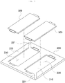
- the battery cells 300 may be inserted into and accommodated in an accommodation space 230 of a cell tray 200 as illustrated in FIGS. 3 and 4 .
- the accommodation space 230 may be formed in an upper surface of the cell tray 200 so as to be concave downward, and a partition wall 220 may extend upward from a bottom wall 210 so as to surround side surfaces of the accommodation space 230.
- a vent channel 221 penetrating through an outer side surface and an inner side surface may be formed in the partition wall 220 of the cell tray 200.
- a pair of accommodation spaces 230 are formed in the cell tray 200 as illustrated in the drawings, one battery cell 300 may be inserted into and accommodated in each accommodation space 230, and the vent channel 221 may be formed so as to communicate with each accommodation space 230.
- the vent channel 221 may be formed on each of opposite sides in a diagonal direction.
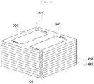
- a plurality of cell-accommodated bodies in which the battery cells 300 are accommodated in the cell trays 200 may be stacked in a height direction as illustrated in FIG. 5 and housed in the case 510.
- the cover 520 may be coupled to an upper side of the case 510 and cover the upper opening of the case 510. Further, the cover 520 may have a flat plate shape that is parallel to the horizontal direction, and may be formed of a material such as plastic. The cover 520 may be formed in various other shapes and may be formed of various other materials.
- the flame discharge port 514 may be formed in the side wall 512 of the case 510, the flame discharge port 514 penetrating through an inner portion and an outer portion of the side wall 512 that is positioned on a side perpendicular to a direction in which the battery cells 300 housed in the case 510 are stacked.
- the number of flame discharge ports 514 may be one, or a plurality of flame discharge ports 514 may be formed while being spaced apart from each other.
- the flame discharge port 514 may be formed at various positions on the side wall 512.
- the flame discharge port 514 may also be formed at a corner where two adjacent side walls 512 meet each other.
- the flame discharge port 514 may be formed at a position that corresponds to a corner where two adjacent side walls 512 meet each other and is adjacent to the bottom wall 511.
- a plurality of flame discharge ports 514 may be formed, and the flame discharge ports 514 may be formed at positions opposite to each other with respect to a central portion surrounded by the side walls 512. That is, as illustrated in the drawings, the flame discharge ports 514 may be formed at opposite vertices in the diagonal direction on a plane.
- the vent channel 221 of the cell tray 200 housed in the carrying box 500 may be formed and arranged so as to face the flame discharge port 514 of the carrying box 500.
- the generated flame when one of the battery cells housed in the battery cell carrying box burns, the generated flame is induced toward the flame discharge portion formed in the carrying box and is discharged to the outside through the flame discharge port. Therefore, the propagation of the flame to the upper and lower sides of the burning battery cell may be delayed and blocked, such that it is possible to prevent the generated flame from being propagated to other adjacent battery cells in the carrying box, thereby preventing the thermal runaway explosion of the battery cells.
- FIG. 6 is a perspective view illustrating a state in which a plurality of battery cell carrying boxes according to the present invention are arranged adjacent to each other and stacked.
- the battery cell carrying boxes 500 according to the present invention in which the battery cells are provided may be loaded in rows and columns on a palette 600 to be carried, and the carrying boxes 500 may be stacked in the height direction.
- the carrying boxes 500 may be stacked adjacent to each other to form one layer, and four carrying boxes 500 may be stacked thereon so that the carrying boxes 500 are loaded in two layers.
- the flame discharge ports 514 of adjacent carrying boxes 500 in each layer may be arranged adjacent to each other.
- the flame discharge port is formed in the carrying box in which the battery cells are housed. Therefore, when a battery cell in any one carrying box burns, it is possible to prevent a flame discharged through the flame discharge port from being propagated to battery cells in adjacent carrying boxes, thereby preventing the thermal runaway explosion of the battery cells.
- FIGS. 7 and 8 are cross-sectional views illustrating examples in which a heat insulation member is formed in the battery cell carrying box according to the present invention.
- heat insulation members 530 formed of a heat insulation material capable of blocking heat transfer may be formed on inner side wall surfaces that form the housing space 502.
- the heat insulation members 530 may be formed on inner side surfaces of the bottom wall 511 and the side walls 512 of the case 510. Further, the heat insulation member 530 may also be formed on a lower surface of the cover 520. Therefore, the housing space 502 formed by coupling the case 510 and the cover 520 is surrounded by the heat insulation members 530, such that it is possible to prevent the carrying box 500 from being deformed or damaged due to a flame when the battery cell 300 in the carrying box 500 burns. Further, a flame generated in the carrying box 500 is discharged only through the flame discharge port 514 and is not discharged through other portions of the carrying box, such that it is possible to prevent the flame from being propagated to another carrying box adjacent to the carrying box in which the burning occurs.
- the heat insulation member 530 may also be formed between the inner side wall surface and an outer side wall surface of each of the case 510 and the cover 520.
- the case 510 and the cover 520 may be formed integrally with the heat insulation members 530 by putting the heat insulation member 530 into a mold and performing injection-molding when manufacturing the case 510 and the cover 520.
- the case 510 and the cover 520 may each have a three-layer structure in which the heat insulation member 530 is interposed between main members 501 included in the case 510 and the cover 520.
- the main member 501 on the inner side of the heat insulation member 530 of the carrying box 500 may be melt or burn and be deformed due to heat and a flame, but the heat insulation member 530 and the main member 501 on the outer side of the heat insulation member 530 are not deformed.
- the flame generated inside the carrying box 500 may be prevented from being discharged through other portions of the carrying box that are not the flame discharge port 514.
- the heat insulation member 530 may be a heat insulation material formed of mica or glass fiber with an excellent fire resistance.
- the mica and glass fiber are nonconductors with an excellent fire resistance, and thus may insulate electricity in addition to heat.
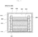
- FIGS. 9 and 10 are cross-sectional views illustrating examples in which a fire extinguishing member is formed in the battery cell carrying box according to the present invention.
- fire extinguishing members 540 capable of discharging a fire extinguishing medium at a specific temperature or higher may be coated on inner side wall surfaces that form the housing space 502.
- the fire extinguishing members 540 may be formed on inner side surfaces of the bottom wall 511 and the side walls 512 of the case 510. Further, the fire extinguishing member 540 may also be formed on the lower surface of the cover 520.
- the housing space 502 formed by coupling the case 510 and the cover 520 is surrounded by the fire extinguishing members 540, and thus, when the battery cell 300 in the carrying box 500 burns and a flame is discharged through the flame discharge port 514, the fire extinguishing medium may be discharged from the fire extinguishing members 540 to extinguish the flame.
- the fire extinguishing member 540 may include a base member 541 and capsules 542 Further, the fire extinguishing member 540 may be formed by applying, onto the inner walls of the case 510 and the cover 520, a paint containing the base member 541 and the capsules 542 that burst at a specific temperature or higher to discharge the fire extinguishing medium. Therefore, the base member 541 may form the appearance of a coating layer formed using the fire extinguishing member 540, and the capsules 542 may be incorporated or contained in the base member 541.
- the fire extinguishing member 540 may be formed in various other shapes and may be formed by various other methods.
- a pattern 513 is formed in the surface of each of the case 510 and the cover 520 on which the fire extinguishing member 540 is coated, and the fire extinguishing member 540 may be coated so that a concave portion 513a of the pattern 513 is filled with the fire extinguishing member 540.
- the fire extinguishing member 540 may be coated so as to cover a convex portion 513b of the pattern 513. That is, as illustrated in FIG. 10 , the pattern 513 having a specific shape in which the relatively concave portion 513a and the relatively convex portion 513b are provided may be formed on the inner side surface of each of the case 510 and the cover 520.
- the fire extinguishing member 540 when the fire extinguishing member 540 is coated on the inner side surface of each of the case 510 and the cover 520, the fire extinguishing member 540 may be coated so that the concave portion 513a is filled with the fire extinguishing member 540, and at the same time, the convex portion 513b is covered with the fire extinguishing member 540.
- the concave portion 513a and the convex portion 513b of the pattern 513 may have various shapes.
- the contact area of the surface on which the fire extinguishing member 540 is coated may be increased, such that it is possible to prevent the fire extinguishing member 540 from being separated from the case 510 and the cover 520.
- a larger amount of the fire extinguishing member 540 may be coated within a predetermined thickness range and a predetermined area range, and thus, it is possible to improve fire extinguishing performance for the burning of the battery cell.
- FIGS. 11 and 12 are cross-sectional views illustrating examples in which the heat insulation member and the fire extinguishing member are formed in the battery cell carrying box according to the present invention.
- the heat insulation members 530 formed of a heat insulation material capable of blocking heat transfer may be formed on the inner side wall surfaces that form the housing space 502, and the fire extinguishing members 540 capable of discharging the fire extinguishing medium at a specific temperature or higher may be coated on inner side surfaces of the heat insulation members 530. Further, both of the heat insulation member 530 and the fire extinguishing member 540 may be formed on the case 510 and the cover 520.
- the case 510 and the cover 520 may each have a three-layer structure in which the heat insulation member 530 is formed on an inner side surface of the main member 501 included in the case 510 and the cover 520, and the fire extinguishing member 540 is coated on the inner side surface of the heat insulation member 530.
- both of the heat insulation member 530 and the fire extinguishing member 540 are formed on the case 510 and the cover 520, but unlike those of FIG. 11 described above, the heat insulation member 530 may be formed between the main members 501 included in the case 510 and the cover 520 to form a three-layer structure, and the fire extinguishing member 540 may be coated on the inner side surface of each of the case 510 and the cover 520 to form a four-layer structure.
- the battery cell 300 may have a rectangular plate shape whose length and width are larger than the thickness thereof.
- the battery cell 300 may be a pouch type secondary battery in which an electrode assembly including a positive plate and a negative plate alternately stacked in a thickness direction with a separator interposed therebetween is housed and sealed in a pouch-shaped exterior material, and the pouch-shaped exterior material is filled with an electrolyte.
- electrode tabs connected to the positive plates and the negative plates may be exposed to the outside of the pouch-shaped exterior material, and for example, the electrode tabs may be exposed at opposite side surfaces of the battery cell 300 in a length direction.
- the battery cell may have various other forms.
- the battery cell 300 may have a form in which a sealing portion of a pouch, which is an exterior material, protrudes from a side surface in a lateral direction or longitudinal direction, or protrudes from the side surface in the lateral direction or longitudinal direction and is bent. Such a battery cell 300 may be inserted into and accommodated in the cell tray 200. Further, a plurality of assemblies in which the battery cells 300 are accommodated in the cell trays 200 may be stacked in a vertical direction and housed in the carrying box 500.
- a sealing portion of a pouch which is an exterior material
- the battery cell carrying box according to the present invention may suppress, when a certain carrying box in which battery cells are housed burns at the time of carrying the battery cells, heat and a flame from being propagated to other surrounding carrying boxes, thereby preventing a thermal runaway explosion of the battery cells.
Landscapes
- Chemical & Material Sciences (AREA)
- Chemical Kinetics & Catalysis (AREA)
- General Chemical & Material Sciences (AREA)
- Electrochemistry (AREA)
- Engineering & Computer Science (AREA)
- Mechanical Engineering (AREA)
- Business, Economics & Management (AREA)
- Emergency Management (AREA)
- Manufacturing & Machinery (AREA)
- Health & Medical Sciences (AREA)
- Public Health (AREA)
- Battery Mounting, Suspending (AREA)
Abstract
The present invention relates to a battery cell carrying box in which battery cells are housed and which has a flame discharge port to discharge a flame when a certain battery cell housed in the carrying box burns, such that it is possible to prevent the flame from being propagated to adjacent battery cells and prevent the flame from being propagated to adjacent carrying boxes.
Description
- The following disclosure relates to a battery cell carrying box, which may prevent, when battery cells are housed in carrying boxes and carried, a thermal runaway explosion in which heat and a flame caused by burning of a certain carrying box in which a battery cell is housed from being propagated to other surrounding carrying boxes.
- In general, depending on the shape of an exterior material, lithium secondary batteries may be classified into a can type secondary battery in which an electrode assembly is embedded in a metal can, and a pouch type secondary battery in which an electrode assembly is embedded in a pouch-shaped exterior material which is an aluminum laminate sheet.
- The lithium secondary battery has been widely used not only in a small-sized mobile device, but also in a middle-sized and large-sized device such as a vehicle or power storage device, and a plurality of battery cells such as pouch type secondary batteries that may be easily stacked and are light are connected at the time of use in order to increase capacity and power.
- Such battery cells are accommodated in trays having a specific shape to be carried, and the trays in which the battery cells are accommodated are stacked and arranged in a carrying box and then carried. Here, an expanded polystyrene pad for absorbing shock may be interposed between the trays in which the battery cells are accommodated.
- However, when any one of the battery cells housed in the carrying box burns, heat and a flame are propagated to other surrounding battery cells, and as a result, a thermal runaway explosion may occur. Further, a carrying box according to the related art is formed of a plastic material and does not have a structure capable of delaying or blocking the burning of a battery cell housed therein.
- Therefore, when any one of the battery cell carrying boxes according to the related art in which the battery cell is housed burns, heat and a flame are propagated to other surrounding carrying boxes, and as a result, a thermal runaway explosion may occur.
- An embodiment of the present invention is directed to providing a battery cell carrying box, which may prevent, when battery cells are housed in carrying boxes and carried, a thermal runaway explosion in which heat and a flame caused by burning of a certain carrying box in which a battery cell is housed are propagated to other surrounding carrying boxes.
- In one general aspect, a battery cell carrying box includes: a container-type case in which a concave housing space is formed to house battery cells therein; and a cover coupled to the case and covering an opening of the case, wherein a flame discharge port is formed in a side wall of the case, the flame discharge port penetrating through an inner portion and an outer portion of the side wall that is positioned on a side perpendicular to a direction in which the battery cells housed in the case are stacked.
- The case may have a bottom wall and side walls extending upward along a circumference of the bottom wall, and the flame discharge port may be formed at a corner where the side walls meet each other.
- The flame discharge port may be formed at a position adjacent to the bottom wall.
- A plurality of flame discharge ports may be formed, and the flame discharge ports may be formed at positions opposite to each other with respect to a central portion surrounded by the side walls.
- In the case and the cover, heat insulation members formed of a heat insulation material that blocks heat transfer may be formed on inner side wall surfaces that form the housing space, or between the inner side wall surfaces and outer side wall surfaces.
- The heat insulation member may be formed of mica or glass fiber.
- In the case and the cover, fire extinguishing members that discharge a fire extinguishing medium at a specific temperature or higher may be coated on inner side wall surfaces that form the housing space.
- The fire extinguishing member may include a base member that forms an appearance, and capsules provided in the base member and in which the fire extinguishing medium is housed, and the fire extinguishing member may be formed so that the capsules burst at the specific temperature or higher to discharge the fire extinguishing medium.
- A specific pattern having a concave portion and a convex portion may be formed on a surface of each of the case and the cover on which the fire extinguishing member is coated, and the concave portion of the pattern may be filled with the fire extinguishing medium.
- The fire extinguishing member may be coated to cover the convex portion of the pattern.
- In the case and the cover, heat insulation members formed of a heat insulation material that blocks heat transfer may be formed on inner side wall surfaces that form the housing space, and fire extinguishing members that discharge a fire extinguishing medium at a specific temperature or higher may be coated on inner side wall surfaces of the heat insulation members.
- In the case and the cover, heat insulation members formed of a heat insulation material that blocks heat transfer may be formed between inner side wall surfaces that form the housing space and outer side wall surfaces, and fire extinguishing members that discharge a fire extinguishing medium at a specific temperature or higher may be coated on the inner side wall surfaces of the case and the cover that form the housing space.
- In another general aspect, a battery cell housing structure includes: a cell tray in which an accommodation space is formed in an upper surface of the cell tray so as to be concave downward to accommodate a battery cell, and a vent channel penetrating through opposite surfaces of a partition wall surrounding side surfaces of the accommodation space is formed in the partition wall; the battery cell inserted into and accommodated in the accommodation space of the cell tray; and the battery cell carrying box described above, wherein cell-accommodated bodies in which the battery cells are accommodated in the cell trays are stacked in a vertical direction in the carrying box.
- The vent channel of the cell tray may be arranged so as to face the flame discharge port of the carrying box.
- Other features and aspects will be apparent from the following detailed description, the drawings, and the claims.
-
-
FIG. 1 is a cross-sectional view illustrating a battery cell carrying box in which battery cells and cell trays are stacked and housed according to an exemplary embodiment of the present invention. -
FIG. 2 is a perspective view illustrating the battery cell carrying box according to an exemplary embodiment of the present invention. -
FIGS. 3 to 5 are perspective views illustrating a structure in which the battery cells are accommodated in the cell tray and a state in which the battery cells and the cell trays are stacked according to the present invention. -
FIG. 6 is a perspective view illustrating a state in which a plurality of battery cell carrying boxes according to the present invention are arranged adjacent to each other and stacked. -
FIGS. 7 and8 are cross-sectional views illustrating examples in which a heat insulation member is formed in the battery cell carrying box according to the present invention. -
FIGS. 9 and10 are cross-sectional views illustrating examples in which a fire extinguishing member is formed in the battery cell carrying box according to the present invention. -
FIGS. 11 and12 are cross-sectional views illustrating examples in which the heat insulation member and the fire extinguishing member are formed in the battery cell carrying box according to the present invention. -
- 200 :
- Cell tray
- 210 :
- Bottom wall
- 220 :
- Partition wall
- 221 :
- Vent channel
- 230 :
- Accommodation space
- 300 :
- Battery cell
- 500 :
- Carrying box
- 501 :
- Main member
- 502 :
- Housing space
- 510 :
- Case
- 511 :
- Bottom wall
- 512 :
- Side wall
- 513 :
- Pattern
- 513a :
- Concave portion
- 513b :
- Convex portion
- 514 :
- Flame discharge port
- 520 :
- Cover
- 530 :
- Heat insulation member
- 540 :
- Fire extinguishing member
- 541 :
- Base member
- 542 :
- Capsule
- 600 :
- Palette
- An exemplary embodiment of the present invention will be described in detail with reference to the accompanying drawings. The following detailed description is only illustrative and illustrates only some exemplary embodiments of the present invention.
-
FIG. 1 is a cross-sectional view illustrating a battery cell carrying box in which battery cells and cell trays are stacked and housed according to an exemplary embodiment of the present invention, andFIG. 2 is a perspective view illustrating the battery cell carrying box according to an exemplary embodiment of the present invention. - Referring to
FIGS. 1 and2 , a batterycell carrying box 500 according to an exemplary embodiment of the present invention may largely include acase 510 and acover 520, and aflame discharge port 514 may be formed in thecase 510. - In the
case 510, an opening that is open upward to allowbattery cells 300 to be housed therein may be formed, and ahousing space 502 communicating with the opening may be formed so as to be concave downward. As an example, thecase 510 may have a hexahedral shape whose upper surface is open, andside walls 512 of thecase 510 may extend upward along a circumference of abottom wall 511 that is formed parallel to a horizontal direction, such that all sides of thecase 510 are surrounded by theside walls 512. Further, thecase 510 may be formed of a material such as plastic. Thecase 510 may be formed in various other shapes and may be formed of various other materials. Further, thebattery cells 300 may be inserted into and housed in thehousing space 502 in thecase 510. - As an example, the
battery cells 300 may be inserted into and accommodated in anaccommodation space 230 of acell tray 200 as illustrated inFIGS. 3 and4 . Theaccommodation space 230 may be formed in an upper surface of thecell tray 200 so as to be concave downward, and apartition wall 220 may extend upward from abottom wall 210 so as to surround side surfaces of theaccommodation space 230. In addition, avent channel 221 penetrating through an outer side surface and an inner side surface may be formed in thepartition wall 220 of thecell tray 200. As an example, a pair ofaccommodation spaces 230 are formed in thecell tray 200 as illustrated in the drawings, onebattery cell 300 may be inserted into and accommodated in eachaccommodation space 230, and thevent channel 221 may be formed so as to communicate with eachaccommodation space 230. Here, thevent channel 221 may be formed on each of opposite sides in a diagonal direction. Further, a plurality of cell-accommodated bodies in which thebattery cells 300 are accommodated in thecell trays 200 may be stacked in a height direction as illustrated inFIG. 5 and housed in thecase 510. - The
cover 520 may be coupled to an upper side of thecase 510 and cover the upper opening of thecase 510. Further, thecover 520 may have a flat plate shape that is parallel to the horizontal direction, and may be formed of a material such as plastic. Thecover 520 may be formed in various other shapes and may be formed of various other materials. - Here, the
flame discharge port 514 may be formed in theside wall 512 of thecase 510, theflame discharge port 514 penetrating through an inner portion and an outer portion of theside wall 512 that is positioned on a side perpendicular to a direction in which thebattery cells 300 housed in thecase 510 are stacked. Here, the number offlame discharge ports 514 may be one, or a plurality offlame discharge ports 514 may be formed while being spaced apart from each other. Theflame discharge port 514 may be formed at various positions on theside wall 512. Theflame discharge port 514 may also be formed at a corner where twoadjacent side walls 512 meet each other. Further, theflame discharge port 514 may be formed at a position that corresponds to a corner where twoadjacent side walls 512 meet each other and is adjacent to thebottom wall 511. A plurality offlame discharge ports 514 may be formed, and theflame discharge ports 514 may be formed at positions opposite to each other with respect to a central portion surrounded by theside walls 512. That is, as illustrated in the drawings, theflame discharge ports 514 may be formed at opposite vertices in the diagonal direction on a plane. Here, thevent channel 221 of thecell tray 200 housed in thecarrying box 500 may be formed and arranged so as to face theflame discharge port 514 of thecarrying box 500. - Therefore, in the battery cell carrying box of the present invention, when one of the battery cells housed in the battery cell carrying box burns, the generated flame is induced toward the flame discharge portion formed in the carrying box and is discharged to the outside through the flame discharge port. Therefore, the propagation of the flame to the upper and lower sides of the burning battery cell may be delayed and blocked, such that it is possible to prevent the generated flame from being propagated to other adjacent battery cells in the carrying box, thereby preventing the thermal runaway explosion of the battery cells.
-
FIG. 6 is a perspective view illustrating a state in which a plurality of battery cell carrying boxes according to the present invention are arranged adjacent to each other and stacked. - Referring to
FIG. 6 , the batterycell carrying boxes 500 according to the present invention in which the battery cells are provided may be loaded in rows and columns on apalette 600 to be carried, and the carryingboxes 500 may be stacked in the height direction. For example, as illustrated inFIG. 6 , four carryingboxes 500 may be arranged adjacent to each other to form one layer, and four carryingboxes 500 may be stacked thereon so that the carryingboxes 500 are loaded in two layers. Here, theflame discharge ports 514 of adjacent carryingboxes 500 in each layer may be arranged adjacent to each other. - Therefore, in the battery cell carrying box of the present invention, the flame discharge port is formed in the carrying box in which the battery cells are housed. Therefore, when a battery cell in any one carrying box burns, it is possible to prevent a flame discharged through the flame discharge port from being propagated to battery cells in adjacent carrying boxes, thereby preventing the thermal runaway explosion of the battery cells.
-
FIGS. 7 and8 are cross-sectional views illustrating examples in which a heat insulation member is formed in the battery cell carrying box according to the present invention. - Referring to
FIG. 7 , in thecase 510 and thecover 520,heat insulation members 530 formed of a heat insulation material capable of blocking heat transfer may be formed on inner side wall surfaces that form thehousing space 502. As an example, theheat insulation members 530 may be formed on inner side surfaces of thebottom wall 511 and theside walls 512 of thecase 510. Further, theheat insulation member 530 may also be formed on a lower surface of thecover 520. Therefore, thehousing space 502 formed by coupling thecase 510 and thecover 520 is surrounded by theheat insulation members 530, such that it is possible to prevent thecarrying box 500 from being deformed or damaged due to a flame when thebattery cell 300 in thecarrying box 500 burns. Further, a flame generated in thecarrying box 500 is discharged only through theflame discharge port 514 and is not discharged through other portions of the carrying box, such that it is possible to prevent the flame from being propagated to another carrying box adjacent to the carrying box in which the burning occurs. - Referring to
FIG. 8 , theheat insulation member 530 may also be formed between the inner side wall surface and an outer side wall surface of each of thecase 510 and thecover 520. As an example, thecase 510 and thecover 520 may be formed integrally with theheat insulation members 530 by putting theheat insulation member 530 into a mold and performing injection-molding when manufacturing thecase 510 and thecover 520. In this way, thecase 510 and thecover 520 may each have a three-layer structure in which theheat insulation member 530 is interposed betweenmain members 501 included in thecase 510 and thecover 520. Therefore, when thebattery cell 300 in thecarrying box 500 burns, themain member 501 on the inner side of theheat insulation member 530 of thecarrying box 500 may be melt or burn and be deformed due to heat and a flame, but theheat insulation member 530 and themain member 501 on the outer side of theheat insulation member 530 are not deformed. As a result, the flame generated inside the carryingbox 500 may be prevented from being discharged through other portions of the carrying box that are not theflame discharge port 514. - As an example, the
heat insulation member 530 may be a heat insulation material formed of mica or glass fiber with an excellent fire resistance. Here, the mica and glass fiber are nonconductors with an excellent fire resistance, and thus may insulate electricity in addition to heat. -
FIGS. 9 and10 are cross-sectional views illustrating examples in which a fire extinguishing member is formed in the battery cell carrying box according to the present invention. - Referring to
FIG. 9 , in thecase 510 and thecover 520,fire extinguishing members 540 capable of discharging a fire extinguishing medium at a specific temperature or higher may be coated on inner side wall surfaces that form thehousing space 502. As an example, thefire extinguishing members 540 may be formed on inner side surfaces of thebottom wall 511 and theside walls 512 of thecase 510. Further, thefire extinguishing member 540 may also be formed on the lower surface of thecover 520. Therefore, thehousing space 502 formed by coupling thecase 510 and thecover 520 is surrounded by thefire extinguishing members 540, and thus, when thebattery cell 300 in thecarrying box 500 burns and a flame is discharged through theflame discharge port 514, the fire extinguishing medium may be discharged from thefire extinguishing members 540 to extinguish the flame. Here, for example, thefire extinguishing member 540 may include abase member 541 andcapsules 542 Further, thefire extinguishing member 540 may be formed by applying, onto the inner walls of thecase 510 and thecover 520, a paint containing thebase member 541 and thecapsules 542 that burst at a specific temperature or higher to discharge the fire extinguishing medium. Therefore, thebase member 541 may form the appearance of a coating layer formed using thefire extinguishing member 540, and thecapsules 542 may be incorporated or contained in thebase member 541. Thefire extinguishing member 540 may be formed in various other shapes and may be formed by various other methods. - Referring to
FIG. 10 , apattern 513 is formed in the surface of each of thecase 510 and thecover 520 on which thefire extinguishing member 540 is coated, and thefire extinguishing member 540 may be coated so that aconcave portion 513a of thepattern 513 is filled with thefire extinguishing member 540. Here, thefire extinguishing member 540 may be coated so as to cover aconvex portion 513b of thepattern 513. That is, as illustrated inFIG. 10 , thepattern 513 having a specific shape in which the relativelyconcave portion 513a and the relativelyconvex portion 513b are provided may be formed on the inner side surface of each of thecase 510 and thecover 520. Therefore, when thefire extinguishing member 540 is coated on the inner side surface of each of thecase 510 and thecover 520, thefire extinguishing member 540 may be coated so that theconcave portion 513a is filled with thefire extinguishing member 540, and at the same time, theconvex portion 513b is covered with thefire extinguishing member 540. Here, theconcave portion 513a and theconvex portion 513b of thepattern 513 may have various shapes. In this case, the contact area of the surface on which thefire extinguishing member 540 is coated may be increased, such that it is possible to prevent thefire extinguishing member 540 from being separated from thecase 510 and thecover 520. In addition, a larger amount of thefire extinguishing member 540 may be coated within a predetermined thickness range and a predetermined area range, and thus, it is possible to improve fire extinguishing performance for the burning of the battery cell. -
FIGS. 11 and12 are cross-sectional views illustrating examples in which the heat insulation member and the fire extinguishing member are formed in the battery cell carrying box according to the present invention. - Referring to
FIG. 11 , in thecase 510 and thecover 520, theheat insulation members 530 formed of a heat insulation material capable of blocking heat transfer may be formed on the inner side wall surfaces that form thehousing space 502, and thefire extinguishing members 540 capable of discharging the fire extinguishing medium at a specific temperature or higher may be coated on inner side surfaces of theheat insulation members 530. Further, both of theheat insulation member 530 and thefire extinguishing member 540 may be formed on thecase 510 and thecover 520. Here, thecase 510 and thecover 520 may each have a three-layer structure in which theheat insulation member 530 is formed on an inner side surface of themain member 501 included in thecase 510 and thecover 520, and thefire extinguishing member 540 is coated on the inner side surface of theheat insulation member 530. - Referring to
FIG. 12 , both of theheat insulation member 530 and thefire extinguishing member 540 are formed on thecase 510 and thecover 520, but unlike those ofFIG. 11 described above, theheat insulation member 530 may be formed between themain members 501 included in thecase 510 and thecover 520 to form a three-layer structure, and thefire extinguishing member 540 may be coated on the inner side surface of each of thecase 510 and thecover 520 to form a four-layer structure. - For reference, the
battery cell 300 may have a rectangular plate shape whose length and width are larger than the thickness thereof. Although not illustrated, thebattery cell 300 may be a pouch type secondary battery in which an electrode assembly including a positive plate and a negative plate alternately stacked in a thickness direction with a separator interposed therebetween is housed and sealed in a pouch-shaped exterior material, and the pouch-shaped exterior material is filled with an electrolyte. Further, in thebattery cell 300, electrode tabs connected to the positive plates and the negative plates may be exposed to the outside of the pouch-shaped exterior material, and for example, the electrode tabs may be exposed at opposite side surfaces of thebattery cell 300 in a length direction. The battery cell may have various other forms. Further, thebattery cell 300 may have a form in which a sealing portion of a pouch, which is an exterior material, protrudes from a side surface in a lateral direction or longitudinal direction, or protrudes from the side surface in the lateral direction or longitudinal direction and is bent. Such abattery cell 300 may be inserted into and accommodated in thecell tray 200. Further, a plurality of assemblies in which thebattery cells 300 are accommodated in thecell trays 200 may be stacked in a vertical direction and housed in thecarrying box 500. - The battery cell carrying box according to the present invention may suppress, when a certain carrying box in which battery cells are housed burns at the time of carrying the battery cells, heat and a flame from being propagated to other surrounding carrying boxes, thereby preventing a thermal runaway explosion of the battery cells.
- Although the present invention has been described and illustrated based on the exemplary embodiments for describing the principle of the present invention, the present invention is not limited to the configurations and actions illustrated and described above. Those skilled in the art will appreciate that various modifications and alterations may be made without departing from the spirit or essential feature of the present invention. Therefore, it is to be understood that the exemplary embodiments described above are illustrative rather than being restrictive in all aspects. It is to be understood that the scope of the present invention will be defined by the claims and all modifications and alterations derived from the claims and their equivalents are included in the scope of the present invention.
Claims (14)
- A battery cell carrying box comprising:a container-type case in which a concave housing space is formed to house battery cells therein; anda cover coupled to the case and covering an opening of the case,wherein a flame discharge port is formed in a side wall of the case, the flame discharge port penetrating through an inner portion and an outer portion of the side wall that is positioned on a side perpendicular to a direction in which the battery cells housed in the case are stacked.
- The battery cell carrying box of claim 1, wherein the case has a bottom wall and side walls extending upward along a circumference of the bottom wall, and
the flame discharge port is formed at a corner where the side walls meet each other. - The battery cell carrying box claim 2, wherein the flame discharge port is formed at a position adjacent to the bottom wall.
- The battery cell carrying box of claim 2, wherein a plurality of flame discharge ports are formed, and
the flame discharge ports are formed at positions opposite to each other with respect to a central portion surrounded by the side walls. - The battery cell carrying box of claim according to one of proceeding claims, wherein in the case and the cover, heat insulation members formed of a heat insulation material that blocks heat transfer are formed on inner side wall surfaces that form the housing space, or between the inner side wall surfaces and outer side wall surfaces.
- The battery cell carrying box according to one of proceeding claims, wherein the heat insulation member is formed of mica or glass fiber.
- The battery cell carrying box according to one of proceeding claims, wherein in the case and the cover, fire extinguishing members that discharge a fire extinguishing medium at a specific temperature or higher are coated on inner side wall surfaces that form the housing space.
- The battery cell carrying box according to one of proceeding claims, wherein the fire extinguishing member includes a base member that forms an appearance, and capsules provided in the base member and in which the fire extinguishing medium is housed, and
the fire extinguishing member is formed so that the capsules burst at the specific temperature or higher to discharge the fire extinguishing medium. - The battery cell carrying box according to one of proceeding claims, wherein a specific pattern having a concave portion and a convex portion is formed on a surface of each of the case and the cover on which the fire extinguishing member is coated, and
the concave portion of the specific pattern is filled with the fire extinguishing member. - The battery cell carrying box according to one of proceeding claims, wherein the fire extinguishing member is coated to cover the convex portion of the specific pattern.
- The battery cell carrying box according to one of proceeding claims, wherein in the case and the cover, heat insulation members formed of a heat insulation material that blocks heat transfer are formed on inner side wall surfaces that form the housing space, and fire extinguishing members that discharge a fire extinguishing medium at a specific temperature or higher are coated on inner side wall surfaces of the heat insulation members.
- The battery cell carrying box according to one of proceeding claims, wherein in the case and the cover, heat insulation members formed of a heat insulation material that blocks heat transfer are formed between inner side wall surfaces that form the housing space and outer side wall surfaces, and fire extinguishing members that discharge a fire extinguishing medium at a specific temperature or higher are coated on the inner side wall surfaces of the case and the cover that form the housing space.
- A battery cell housing structure comprising:a cell tray in which an accommodation space is formed in an upper surface of the cell tray so as to be concave downward to accommodate a battery cell, and a vent channel penetrating through opposite surfaces of a partition wall surrounding side surfaces of the accommodation space is formed in the partition wall;the battery cell inserted into and accommodated in the accommodation space of the cell tray; andthe battery cell carrying box of any one of claims 1 to 12,wherein cell-accommodated bodies in which the battery cells are accommodated in the cell trays are stacked in a vertical direction in the carrying box.
- The battery cell housing structure of claim 13, wherein the vent channel of the cell tray is arranged so as to face the flame discharge port of the carrying box.
Applications Claiming Priority (1)
| Application Number | Priority Date | Filing Date | Title |
|---|---|---|---|
| KR1020200054335A KR102752394B1 (en) | 2020-05-07 | 2020-05-07 | Carrying box for battery cell |
Publications (1)
| Publication Number | Publication Date |
|---|---|
| EP3907817A1 true EP3907817A1 (en) | 2021-11-10 |
Family
ID=75825447
Family Applications (1)
| Application Number | Title | Priority Date | Filing Date |
|---|---|---|---|
| EP21172130.3A Pending EP3907817A1 (en) | 2020-05-07 | 2021-05-04 | Battery cell carrying box |
Country Status (4)
| Country | Link |
|---|---|
| US (1) | US11799163B2 (en) |
| EP (1) | EP3907817A1 (en) |
| KR (1) | KR102752394B1 (en) |
| CN (1) | CN113629335A (en) |
Families Citing this family (12)
| Publication number | Priority date | Publication date | Assignee | Title |
|---|---|---|---|---|
| JP7388389B2 (en) * | 2021-03-31 | 2023-11-29 | トヨタ自動車株式会社 | Manufacturing method of power storage device |
| KR102639748B1 (en) * | 2021-12-27 | 2024-02-21 | 주식회사 엘지에너지솔루션 | Battery module, battery pack the battery module, energy storage system and vehicle comprising the battery pack |
| KR102484141B1 (en) * | 2022-06-21 | 2023-01-04 | 그래버 주식회사 | Vehicle battery transport vehicle |
| KR102718760B1 (en) * | 2022-08-31 | 2024-10-18 | (주)비에이에너지 | Reusable Battery Storage and Transport Box |
| KR20240082096A (en) * | 2022-12-01 | 2024-06-10 | 에스케이온 주식회사 | Battery Pack |
| KR102597611B1 (en) * | 2023-02-21 | 2023-11-02 | (주) 제이에스테크놀로지 | Secondary Battery Cell Packing Method And Secondary Battery Cell Package |
| KR102727000B1 (en) | 2023-06-12 | 2024-11-06 | (주)광동 | Waste Batteries Packaging boxes |
| KR20250043697A (en) | 2023-09-22 | 2025-03-31 | 그래버 주식회사 | Battery Transportation Vehicle Equipped with Non-Combustible and Insulating Function |
| KR20250043701A (en) | 2023-09-22 | 2025-03-31 | 그래버 주식회사 | Battery Transport Vehicle with Internal Pressure Control Function |
| KR20250118880A (en) | 2024-01-30 | 2025-08-07 | 서진산업 주식회사 | Prefabricated pallet for electric vehicle battery pack case |
| US20260109507A1 (en) * | 2024-10-17 | 2026-04-23 | Dong Yang Physics & Chemical Co., Ltd. | Battery cell tray for transporting battery cell |
| KR102786400B1 (en) * | 2024-10-25 | 2025-03-26 | 주식회사 프로와이즈에너지 | Thermal Runaway Preventing Battery Cell and Manufacturing Method thereof |
Citations (4)
| Publication number | Priority date | Publication date | Assignee | Title |
|---|---|---|---|---|
| KR101973741B1 (en) * | 2017-07-17 | 2019-04-30 | 에스케이이노베이션 주식회사 | Battery Cell Common Tray |
| WO2020152992A1 (en) * | 2019-01-25 | 2020-07-30 | 三洋電機株式会社 | Battery pack |
| WO2021020003A1 (en) * | 2019-07-29 | 2021-02-04 | 三洋電機株式会社 | Battery pack |
| EP3790101A1 (en) * | 2019-09-05 | 2021-03-10 | Samsung SDI Co., Ltd. | Energy storage module |
Family Cites Families (15)
| Publication number | Priority date | Publication date | Assignee | Title |
|---|---|---|---|---|
| KR100872616B1 (en) * | 2004-03-31 | 2008-12-09 | 닛본 덴끼 가부시끼가이샤 | Electrical device with film covering, frame member, and housing system for electrical device with film covering |
| US8147997B2 (en) * | 2005-10-14 | 2012-04-03 | Nec Corporation | Film-covered electrical device packaging system |
| KR100852727B1 (en) | 2007-02-21 | 2008-08-19 | 주식회사 에이티티알앤디 | Battery pack |
| DE102010034825A1 (en) * | 2010-08-19 | 2012-02-23 | Li-Tec Battery Gmbh | Electrochemical energy storage |
| JP5492738B2 (en) | 2010-11-05 | 2014-05-14 | 日立ビークルエナジー株式会社 | Secondary battery and secondary battery module |
| DE102011009696A1 (en) * | 2011-01-28 | 2012-08-02 | Li-Tec Battery Gmbh | Transport device for electrochemical energy storage devices |
| KR20130068982A (en) * | 2011-12-16 | 2013-06-26 | (주)브이이엔에스 | Battery module assembly and electric vehicle having him |
| DE102012003017A1 (en) * | 2012-02-15 | 2013-08-22 | Key Safety Systems, Inc. | Fire prevention or fire elimination in an electrochemical energy storage |
| KR101404685B1 (en) | 2012-02-17 | 2014-06-09 | 주식회사 에이치디에스 | Battary transport tray |
| JP5933344B2 (en) * | 2012-05-31 | 2016-06-08 | 三洋電機株式会社 | Power supply |
| KR20150029532A (en) * | 2013-09-09 | 2015-03-18 | 정윤이 | Battery module |
| KR101787638B1 (en) * | 2014-11-05 | 2017-10-19 | 주식회사 엘지화학 | Cartridge Frame Having Double Sidewall Structure and Battery Module Having the Same |
| KR102249891B1 (en) | 2016-08-31 | 2021-05-07 | 삼성에스디아이 주식회사 | Rechargeable battery module |
| JP6479924B1 (en) * | 2017-10-03 | 2019-03-06 | カルソニックカンセイ株式会社 | Manufacturing method of assembled battery and assembled battery |
| KR102330377B1 (en) * | 2018-10-12 | 2021-11-22 | 주식회사 엘지에너지솔루션 | Battery module, battery rack comprising the battery module, and energy storage system comprising the battery rack |
-
2020
- 2020-05-07 KR KR1020200054335A patent/KR102752394B1/en active Active
-
2021
- 2021-05-04 EP EP21172130.3A patent/EP3907817A1/en active Pending
- 2021-05-05 US US17/308,460 patent/US11799163B2/en active Active
- 2021-05-07 CN CN202110495936.6A patent/CN113629335A/en active Pending
Patent Citations (4)
| Publication number | Priority date | Publication date | Assignee | Title |
|---|---|---|---|---|
| KR101973741B1 (en) * | 2017-07-17 | 2019-04-30 | 에스케이이노베이션 주식회사 | Battery Cell Common Tray |
| WO2020152992A1 (en) * | 2019-01-25 | 2020-07-30 | 三洋電機株式会社 | Battery pack |
| WO2021020003A1 (en) * | 2019-07-29 | 2021-02-04 | 三洋電機株式会社 | Battery pack |
| EP3790101A1 (en) * | 2019-09-05 | 2021-03-10 | Samsung SDI Co., Ltd. | Energy storage module |
Also Published As
| Publication number | Publication date |
|---|---|
| KR102752394B1 (en) | 2025-01-13 |
| KR20210137271A (en) | 2021-11-17 |
| US20210351471A1 (en) | 2021-11-11 |
| CN113629335A (en) | 2021-11-09 |
| US11799163B2 (en) | 2023-10-24 |
Similar Documents
| Publication | Publication Date | Title |
|---|---|---|
| US11799163B2 (en) | Battery cell carrying box | |
| JP7651635B2 (en) | Pouch exterior material, and secondary battery and secondary battery pack using the same | |
| KR102924941B1 (en) | Battery module | |
| KR102830482B1 (en) | Pouch case for secondary battery and secondary battery cell using the same | |
| JP7401467B2 (en) | pack batteries | |
| KR102910323B1 (en) | Pad for preventing thermal runaway and accommodating structure of battery cell having the same | |
| KR20230112413A (en) | Battery Pack | |
| US12362426B2 (en) | Battery pack having thermal diffusion prevention structure between battery modules | |
| KR20210127415A (en) | Battery pack | |
| KR102880677B1 (en) | Battery module and, battery pack and vehicle including same | |
| KR102861470B1 (en) | Cell tray for preventing heat runaway of battery cell and accommodation structure having the same | |
| KR102695623B1 (en) | Pouch case for secondary battery and secondary battery cell using the same | |
| KR102317273B1 (en) | Battery module having a crush plate and Method for manufacturing the same | |
| CN118872137A (en) | Battery Pack | |
| KR102754518B1 (en) | Battery pack with improved safety | |
| CN115799727A (en) | Battery pack | |
| CN221947346U (en) | Battery pack | |
| US20240372235A1 (en) | Battery pack with improved safety | |
| JP2025534424A (en) | Battery pack with improved fire prevention performance | |
| KR102926749B1 (en) | Formaion tray and formaion tray stack using the same | |
| KR102955144B1 (en) | Battery module | |
| CN117999696A (en) | Battery pack with improved safety | |
| KR102865416B1 (en) | Pouch case for secondary battery and manufacturing method thereof | |
| AU2022429094B2 (en) | Battery pack with improved safety | |
| KR102945209B1 (en) | Battery pack and energy storage device including the same |
Legal Events
| Date | Code | Title | Description |
|---|---|---|---|
| PUAI | Public reference made under article 153(3) epc to a published international application that has entered the european phase |
Free format text: ORIGINAL CODE: 0009012 |
|
| STAA | Information on the status of an ep patent application or granted ep patent |
Free format text: STATUS: REQUEST FOR EXAMINATION WAS MADE |
|
| 17P | Request for examination filed |
Effective date: 20210504 |
|
| AK | Designated contracting states |
Kind code of ref document: A1 Designated state(s): AL AT BE BG CH CY CZ DE DK EE ES FI FR GB GR HR HU IE IS IT LI LT LU LV MC MK MT NL NO PL PT RO RS SE SI SK SM TR |
|
| B565 | Issuance of search results under rule 164(2) epc |
Effective date: 20211011 |
|
| RAP1 | Party data changed (applicant data changed or rights of an application transferred) |
Owner name: SK ON CO., LTD. |
|
| P01 | Opt-out of the competence of the unified patent court (upc) registered |
Effective date: 20230602 |