EP3907800A1 - Negative electrode sheet, preparation method thereof and lithium ion battery containing the same - Google Patents
Negative electrode sheet, preparation method thereof and lithium ion battery containing the same Download PDFInfo
- Publication number
- EP3907800A1 EP3907800A1 EP20214605.6A EP20214605A EP3907800A1 EP 3907800 A1 EP3907800 A1 EP 3907800A1 EP 20214605 A EP20214605 A EP 20214605A EP 3907800 A1 EP3907800 A1 EP 3907800A1
- Authority
- EP
- European Patent Office
- Prior art keywords
- negative electrode
- active material
- electrode active
- material layer
- current collector
- Prior art date
- Legal status (The legal status is an assumption and is not a legal conclusion. Google has not performed a legal analysis and makes no representation as to the accuracy of the status listed.)
- Granted
Links
Images
Classifications
-
- H—ELECTRICITY
- H01—ELECTRIC ELEMENTS
- H01M—PROCESSES OR MEANS, e.g. BATTERIES, FOR THE DIRECT CONVERSION OF CHEMICAL ENERGY INTO ELECTRICAL ENERGY
- H01M10/00—Secondary cells; Manufacture thereof
- H01M10/04—Construction or manufacture in general
- H01M10/0404—Machines for assembling batteries
-
- H—ELECTRICITY
- H01—ELECTRIC ELEMENTS
- H01M—PROCESSES OR MEANS, e.g. BATTERIES, FOR THE DIRECT CONVERSION OF CHEMICAL ENERGY INTO ELECTRICAL ENERGY
- H01M4/00—Electrodes
- H01M4/02—Electrodes composed of, or comprising, active material
- H01M4/13—Electrodes for accumulators with non-aqueous electrolyte, e.g. for lithium-accumulators; Processes of manufacture thereof
- H01M4/133—Electrodes based on carbonaceous material, e.g. graphite-intercalation compounds or CFx
-
- H—ELECTRICITY
- H01—ELECTRIC ELEMENTS
- H01M—PROCESSES OR MEANS, e.g. BATTERIES, FOR THE DIRECT CONVERSION OF CHEMICAL ENERGY INTO ELECTRICAL ENERGY
- H01M4/00—Electrodes
- H01M4/02—Electrodes composed of, or comprising, active material
- H01M4/04—Processes of manufacture in general
- H01M4/0402—Methods of deposition of the material
- H01M4/0404—Methods of deposition of the material by coating on electrode collectors
-
- H—ELECTRICITY
- H01—ELECTRIC ELEMENTS
- H01M—PROCESSES OR MEANS, e.g. BATTERIES, FOR THE DIRECT CONVERSION OF CHEMICAL ENERGY INTO ELECTRICAL ENERGY
- H01M10/00—Secondary cells; Manufacture thereof
- H01M10/05—Accumulators with non-aqueous electrolyte
- H01M10/052—Li-accumulators
- H01M10/0525—Rocking-chair batteries, i.e. batteries with lithium insertion or intercalation in both electrodes; Lithium-ion batteries
-
- H—ELECTRICITY
- H01—ELECTRIC ELEMENTS
- H01M—PROCESSES OR MEANS, e.g. BATTERIES, FOR THE DIRECT CONVERSION OF CHEMICAL ENERGY INTO ELECTRICAL ENERGY
- H01M10/00—Secondary cells; Manufacture thereof
- H01M10/05—Accumulators with non-aqueous electrolyte
- H01M10/058—Construction or manufacture
- H01M10/0587—Construction or manufacture of accumulators having only wound construction elements, i.e. wound positive electrodes, wound negative electrodes and wound separators
-
- H—ELECTRICITY
- H01—ELECTRIC ELEMENTS
- H01M—PROCESSES OR MEANS, e.g. BATTERIES, FOR THE DIRECT CONVERSION OF CHEMICAL ENERGY INTO ELECTRICAL ENERGY
- H01M4/00—Electrodes
- H01M4/02—Electrodes composed of, or comprising, active material
- H01M4/13—Electrodes for accumulators with non-aqueous electrolyte, e.g. for lithium-accumulators; Processes of manufacture thereof
-
- H—ELECTRICITY
- H01—ELECTRIC ELEMENTS
- H01M—PROCESSES OR MEANS, e.g. BATTERIES, FOR THE DIRECT CONVERSION OF CHEMICAL ENERGY INTO ELECTRICAL ENERGY
- H01M4/00—Electrodes
- H01M4/02—Electrodes composed of, or comprising, active material
- H01M4/13—Electrodes for accumulators with non-aqueous electrolyte, e.g. for lithium-accumulators; Processes of manufacture thereof
- H01M4/139—Processes of manufacture
- H01M4/1393—Processes of manufacture of electrodes based on carbonaceous material, e.g. graphite-intercalation compounds or CFx
-
- H—ELECTRICITY
- H01—ELECTRIC ELEMENTS
- H01M—PROCESSES OR MEANS, e.g. BATTERIES, FOR THE DIRECT CONVERSION OF CHEMICAL ENERGY INTO ELECTRICAL ENERGY
- H01M4/00—Electrodes
- H01M4/02—Electrodes composed of, or comprising, active material
- H01M4/36—Selection of substances as active materials, active masses, active liquids
- H01M4/362—Composites
- H01M4/366—Composites as layered products
-
- H—ELECTRICITY
- H01—ELECTRIC ELEMENTS
- H01M—PROCESSES OR MEANS, e.g. BATTERIES, FOR THE DIRECT CONVERSION OF CHEMICAL ENERGY INTO ELECTRICAL ENERGY
- H01M4/00—Electrodes
- H01M4/02—Electrodes composed of, or comprising, active material
- H01M2004/021—Physical characteristics, e.g. porosity, surface area
-
- H—ELECTRICITY
- H01—ELECTRIC ELEMENTS
- H01M—PROCESSES OR MEANS, e.g. BATTERIES, FOR THE DIRECT CONVERSION OF CHEMICAL ENERGY INTO ELECTRICAL ENERGY
- H01M4/00—Electrodes
- H01M4/02—Electrodes composed of, or comprising, active material
- H01M2004/026—Electrodes composed of, or comprising, active material characterised by the polarity
- H01M2004/027—Negative electrodes
-
- Y—GENERAL TAGGING OF NEW TECHNOLOGICAL DEVELOPMENTS; GENERAL TAGGING OF CROSS-SECTIONAL TECHNOLOGIES SPANNING OVER SEVERAL SECTIONS OF THE IPC; TECHNICAL SUBJECTS COVERED BY FORMER USPC CROSS-REFERENCE ART COLLECTIONS [XRACs] AND DIGESTS
- Y02—TECHNOLOGIES OR APPLICATIONS FOR MITIGATION OR ADAPTATION AGAINST CLIMATE CHANGE
- Y02E—REDUCTION OF GREENHOUSE GAS [GHG] EMISSIONS, RELATED TO ENERGY GENERATION, TRANSMISSION OR DISTRIBUTION
- Y02E60/00—Enabling technologies; Technologies with a potential or indirect contribution to GHG emissions mitigation
- Y02E60/10—Energy storage using batteries
-
- Y—GENERAL TAGGING OF NEW TECHNOLOGICAL DEVELOPMENTS; GENERAL TAGGING OF CROSS-SECTIONAL TECHNOLOGIES SPANNING OVER SEVERAL SECTIONS OF THE IPC; TECHNICAL SUBJECTS COVERED BY FORMER USPC CROSS-REFERENCE ART COLLECTIONS [XRACs] AND DIGESTS
- Y02—TECHNOLOGIES OR APPLICATIONS FOR MITIGATION OR ADAPTATION AGAINST CLIMATE CHANGE
- Y02P—CLIMATE CHANGE MITIGATION TECHNOLOGIES IN THE PRODUCTION OR PROCESSING OF GOODS
- Y02P70/00—Climate change mitigation technologies in the production process for final industrial or consumer products
- Y02P70/50—Manufacturing or production processes characterised by the final manufactured product
Definitions
- the present disclosure belongs to the technical field of lithium ion batteries, and specifically relates to a negative electrode sheet, a preparation method thereof and a lithium ion battery containing the same.
- Lithium ion battery is widely used in portable mobile electronic device terminals because of its relatively long circulation life and higher power density.
- people's life rhythm become faster, people raise higher requirement on endurance capability and charging speed thereof.
- fast-charging lithium ion battery has becoming the main developing trend of consumer lithium ion battery.
- the development of the fast-charging lithium ion battery has brought safety problems while bringing convenience to people.
- the negative electrode of lithium ion battery is prone to lithium deposition, especially on a single-sided coating area of the negative electrode. Consequently, the problems of battery capacity circulation plunging, inflating and air-swelling are caused, which greatly reduce the service life of the lithium ion battery.
- the present application provides a negative electrode sheet, a preparation method thereof and a lithium ion battery containing the same.
- the negative electrode sheet is mainly used to solve the problem of lithium deposition of a single-sided coating area of a negative electrode of a winding structural battery cell under high rate fast-charging scheme in a long circulation process.
- the inventor of the present application found out in research that, a fundamental reason for the lithium deposition of the single-sided coating area of the negative electrode of the existing winding structural battery cell is because the single-sided coating area is close to a tab, which result in high current density, low potential, and insufficiency of the negative electrode dynamic property.
- the key to solving the lithium deposition of the single-sided coating area of the negative electrode, under the premise that charging scheme is unchanged, is to increase the dynamics of the negative electrode and/or reduce the dynamics of the a positive electrode.
- the increase of the overall negative electrode dynamic property will inevitably lead to the decrease of the power density of the lithium ion battery.
- the present disclosure provides a negative electrode sheet with specific structure, which, by adjusting dynamic property of active material of a single-sided coating area of a negative electrode of a winding lithium ion battery and dynamic properties of the active material on the overall negative electrode surface, increases the dynamic property of the single-sided coating area of the negative electrode of the lithium ion battery, decreases the polarization of the single-sided coating area of the negative electrode and the overall negative electrode surface, effectively improve the problem of the lithium deposition of the single-sided coating area of the negative electrode of the regular the winding structural lithium ion battery without reducing the battery energy density, increases the circulation lifetime of the lithium ion battery, improve the circulation inflation, and improve the fast-charging performance of the battery without reducing the battery energy density.
- the negative electrode sheet can resolve the problem of the lithium deposition of the single-sided coating area of the negative electrode of the winding structural battery cell under the high rate charging scheme in the long circulation process without reducing the energy density.
- a dynamic property of the first negative electrode active material layer is better than a dynamic property of the second negative electrode active material layer.
- the single-sided coating area refers to coating a negative electrode active material layer to one of the two side surfaces of the current collector.
- the double-sided coating area refers to coating negative electrode active material layers to both sides of the current collector.
- the dynamic property refers a de-intercalation speed of the lithium ions, the faster the de-intercalation speed, the better the dynamic property.
- a factor affecting the de-intercalation speed mainly includes: (1) a supportable charging current of the active material, the larger the supportable charging current, the better the dynamic property; (2) a reception amount of lithium ions per unit time, that is, a reception speed of the lithium ions, the faster the reception speed of the lithium ions, the better the dynamic property.
- a de-intercalation speed of the lithium ions of the first negative electrode active material layer is greater than a de-intercalation speed of the lithium ions of the second negative electrode active material layer.
- a supportable charging current of the first negative electrode active material layer is larger than a supportable charging current of the second negative electrode active material layer.
- a reception speed of the lithium ions of the first negative electrode active material layer is larger than a reception speed of the lithium ions of the second negative electrode active material layer.
- a particle size distribution of the first negative electrode active material forming the first negative electrode active material layer is: 3 ⁇ m ⁇ D10 ⁇ 4 ⁇ m, 5 ⁇ m ⁇ D50 ⁇ 8 ⁇ m, 10 ⁇ m ⁇ D90 ⁇ 13 ⁇ m; a particle size distribution of the second negative electrode active material forming the second negative electrode active material layer is: 5 ⁇ m ⁇ D10 ⁇ 8 ⁇ m, 11 ⁇ m ⁇ D50 ⁇ 14 ⁇ m, 20 ⁇ m ⁇ D90 ⁇ 25 ⁇ m.
- a particle size of the first negative electrode active material forming the first negative electrode active material layer is less than a particle size of the second negative electrode active material forming the second negative electrode active material layer.
- the negative electrode current collector includes a tab area, a single-sided coating area and a double-sided coating area that are sequentially disposed; in the tab area, no coating layer is disposed on both sides of the negative electrode current collector.
- the tab area, the single-sided coating area and double-sided coating area are sequentially disposed in connection, that is, there is no blank area in the tab area, the single-sided coating area and double-sided coating area.
- the first negative electrode active material layer of the first coating layer is connected to the first negative electrode active material layer of the second coating layer.
- a thickness of the first coating layer and thicknesses of the second coating layers are the same.
- thicknesses of the second coating layers on both sides of the negative electrode current collector are the same.
- a length and a width of the current collector are not specifically defined, and current collectors with different lengths and different widths are selected according to the battery cell needed.
- a length of a current collector is 500-1000 mm, such as 885 ⁇ 2 mm
- a width of the current collector is 400-900 mm, such as 773 ⁇ 2 mm.
- a length of the tab area, a length of the single-sided coating area, a length of the double-sided coating area are not specifically defined, and can be set according to different requirements.
- the length of the double-sided coating area is longer than the length of the single-sided coating area, and the length of the double-sided coating area is longer than the length of the tab area.
- a length of a single-sided coating area is 113 ⁇ 2 mm.
- the tab area is disposed with a negative electrode tab, so that there is no need to dispose a coating layer.
- a distance between the negative electrode tab disposed in the tab area and the single-sided coating area is not particularly specified, for example, 10-100 mm; for another example, for a battery of model 386283, a distance between a negative electrode tab disposed in a tab area and a single-sided coating area is 35.5 ⁇ 0.5 mm.
- thicknesses of the second coating layers on both sides of the negative electrode current collector are the same.
- a thickness of the first negative electrode active material layer is 5-30 ⁇ m, such as 5 ⁇ m, 10 ⁇ m, 15 ⁇ m, 20 ⁇ m, 25 ⁇ m or 30 ⁇ m; a thickness of the second negative electrode active material layer is 90-115 ⁇ m, such as 90 ⁇ m, 95 ⁇ m, 100 ⁇ m, 105 ⁇ m, 110 ⁇ m or 115 ⁇ m; and a sum of the thickness of the first negative electrode active material layer and the thickness of the second negative electrode active material layer is 95-120 ⁇ m.
- a thickness of the first coating layer that is, the thickness of the first negative electrode active material is less or equal than 120 ⁇ m, such as 95 ⁇ m, 100 ⁇ m, 105 ⁇ m, 110 ⁇ m or 115 ⁇ m.
- the negative electrode current collector optionally further includes a blank area, the blank area is disposed on the other side of the double-sided coating area which is connected to the single-sided coating area, the blank area is generated, for example, in order to avoid cutting an active material layer of a surface of the negative electrode current collector during a production process of the negative electrode sheet, a length of the blank area may be, for example, 0.5-2 mm, such as 1mm.
- the negative electrode current collector starting from an end thereof and along a length direction of the negative electrode current collector, includes a tab area, a single-sided coating area and a double-sided coating area that are disposed sequentially; in the single-sided coating area, namely BC section area in surface M, the first coating layer including the first negative electrode active material layer is coated on a side surface of the negative electrode current collector; in the double-sided coating area, namely AB section area of the surface M and the ED section area of surface N, the second coating layers each including the first negative electrode active material layer and the second negative electrode active material layer are coated on both side surfaces of the negative electrode current collector, and the second negative electrode active material layer is coated on a surface of the negative electrode current collector, the first negative electrode active material layer is coated on a surface of the second negative electrode active material layer; in a preparation process of the negative electrode sheet having the above-mentioned structure, a preparation of the surface M may be that, for example, a slurry forming
- a preparation of the surface N may be that, for example, the slurry forming the first negative electrode active material layer and the slurry forming the second negative electrode active material layer are coated altogether from end E of the negative electrode current collector, where the slurry forming the second negative electrode active material layer is close to the negative electrode current collector, the slurry forming the first negative electrode active material layer is away from the negative electrode current collector; and the coating of the slurry forming the second negative electrode active material layer is ended at end D, or, the slurry forming the first negative electrode active material layer and the slurry forming the second negative electrode active material layer are coated altogether from end D of the negative electrode current collector, where the slurry forming the second negative electrode active material layer is close to the negative electrode current collector, the slurry forming the first negative electrode active material layer is away from the negative electrode current collector; and the coating of the slurry forming the second negative electrode active material layer is ended at end E; a line connecting end E and end A
- the first negative electrode active material layer includes the first negative electrode active material, a first conductive agent and a first adhesive agent
- the second negative electrode active material layer includes the second negative electrode active material, a second conductive agent and a second adhesive agent.
- the first negative electrode active material and the second negative electrode active material respectively forming the first negative electrode active material layer and the second negative electrode active material layer are the same or different
- the first conductive agent and the second conductive agent are the same or different
- the first adhesive agent and the second adhesive agent are the same or different.
- a mass percentage of each component in the first negative electrode active material layer is: 70-99 wt% of the first negative electrode active material, 0.5-15 wt% of the first conductive agent, and 0.5-15 wt% of the first adhesive agent; where a particle size distribution of the first negative electrode active material is: 3 ⁇ m ⁇ D10 ⁇ 4 ⁇ m, 5 ⁇ m ⁇ D50 ⁇ 8 ⁇ m, and 10 ⁇ m ⁇ D90 ⁇ 13 ⁇ m.
- the mass percentage of each component in the first negative electrode active material layer is: 80-98 wt% of the first negative electrode active material, 1-10 wt% of the first conductive agent, and 1-10 wt% of the first adhesive agent.
- a mass percentage of each component in the second negative electrode active material layer is: 70-99 wt% of the second negative electrode active material, 0.5-15 wt% of the second conductive agent, and 0.5-15 wt% of the second adhesive agent; where a particle size distribution of the second negative electrode active material is: 5 ⁇ m ⁇ D10 ⁇ 8 ⁇ m, 11 ⁇ m ⁇ D50 ⁇ 14 ⁇ m, and 20 ⁇ m ⁇ D90 ⁇ 25 ⁇ m.
- the mass percentage of each component in the second negative electrode active material layer is: 80-98 wt% of the second negative electrode active material, 1-10 wt% of the second conductive agent, and 1-10 wt% of the second adhesive agent.
- the first conductive agent and the second conductive agent are the same or different, and are independently selected from at least one of conductive carbon black, acetylene black, Ketjen black, conductive graphite, conductive carbon fiber, carbon nanotube, metal powder, and carbon fiber.
- the first adhesive agent and the second adhesive agent are the same or different, and are independently selected from at least one of sodium carboxymethyl cellulose, styrene butadiene latex, polytetrafluoroethylene, and polyethylene oxide.
- the first negative electrode active material and the second negative electrode active material are the same or different, and are independently selected from at least one of artificial graphite, natural graphite, mesocarbon microspheres, and lithium titanate; preferably, the particle size distribution of the first negative electrode active material is: 3 ⁇ m ⁇ D10 ⁇ 4 ⁇ m, 5 ⁇ m ⁇ D50 ⁇ 8 ⁇ m, 10 ⁇ m ⁇ D90 ⁇ 13 ⁇ m; the particle size distribution of the second negative electrode active material is: 5 ⁇ m ⁇ D10 ⁇ 8 ⁇ m, 11 ⁇ m ⁇ D50 ⁇ 14 ⁇ m, 20 ⁇ m ⁇ D90 ⁇ 25 ⁇ m; and the particle size distribution of the first negative electrode active material is larger than that of the second negative electrode active material.
- the present disclosure further provides a preparation method of the above-mentioned negative electrode sheet, and the method includes the following steps:
- a solid content of the slurry forming the first negative electrode active material layer and the slurry forming the second negative electrode active material layer is 40 wt% to 45 wt%.
- step 2) on a side surface of the negative electrode current collector, the slurry forming the first negative electrode active material layer and the slurry forming the second negative electrode active material layer are coated altogether from end A of the negative electrode current collector, where the slurry forming the second negative electrode active material layer is close to the negative electrode current collector, the slurry forming the first negative electrode active material layer is away from the negative electrode current collector; the coating of the slurry forming the second negative electrode active material layer is ended at end B, the coating of the slurry forming the first negative electrode active material layer is kept and ended at end C, where an area between end A and end B is the double-sided coating area, an area between end B and end C is the single-sided coating area, the thickness of the first coating layer of the single-sided coating area and the thicknesses of the second coating layers of the double-sided coating area are the same.
- step 2) on the other side surface of the negative electrode current collector, the slurry forming the first negative electrode active material layer and the slurry forming the second negative electrode active material layer are coated altogether from end E of the negative electrode current collector, where the slurry forming the second negative electrode active material layer is close to the negative electrode current collector, the slurry forming the first negative electrode active material layer is away from the negative electrode current collector; and the coating of the slurry forming the second negative electrode active material layer is ended at end D, or, the slurry forming the first negative electrode active material layer and the slurry forming the second negative electrode active material layer are coated altogether from end D of the negative electrode current collector, where the slurry forming the second negative electrode active material layer is close to the negative electrode current collector, the slurry forming the first negative electrode active material layer is away from the negative electrode current collector; and the coating of the slurry forming the second negative electrode active material layer is ended at end E; a line connecting end E and end A is perpendicular to
- the present disclosure further provides a lithium ion battery, including the above-mentioned negative electrode sheet.
- the battery further includes a positive electrode sheet and a separator.
- the present disclosure provides a negative electrode sheet, a preparation method thereof and a lithium ion battery containing the same.
- the lithium ion battery containing the negative electrode sheet has the following effects:
- experiment methods used in the following embodiments are conventional methods unless otherwise specified; the reagents, materials, or the like, used in the following embodiments can be all obtained from commercial sources unless otherwise specified.
- the negative electrode sheet prepared in the following embodiments is used for a battery of model 386283, where a distance between a negative electrode tab disposed in a tab area and a single-sided coating area is 35.5 ⁇ 0.5 mm, and a length of the single-sided coating area is 113 ⁇ 2 mm, a length of a current collector is 885 ⁇ 2 mm, and a width of the current collector is 773 ⁇ 2 mm.
- the first step prepare a slurry forming a first negative electrode active material layer: add a first negative electrode active material (artificial graphite), a first conductive agent (conductive carbon black) and a first adhesive agent (sodium carboxymethyl cellulose) into a stirring tank according to a mass ratio of 97:1.5:1.5, add deionized water to prepare the slurry forming the first negative electrode active material layer, a solid content of the negative electrode slurry is 40 wt% ⁇ 45 wt%; where a particle size distribution of the first negative electrode active material is: 3 ⁇ m ⁇ D10 ⁇ 4 ⁇ m, 5 ⁇ m ⁇ D50 ⁇ 8 ⁇ m, 10 ⁇ m ⁇ D90 ⁇ 13 ⁇ m.
- a first negative electrode active material artificial graphite
- a first conductive agent conductive carbon black
- a first adhesive agent sodium carboxymethyl cellulose
- the second step prepare a slurry forming a second negative electrode active material layer: add a second negative electrode active material (artificial graphite), a second conductive agent (conductive carbon black) and a second adhesive agent (sodium carboxymethyl cellulose) into a stirring tank according to a mass ratio of 97:1.5:1.5, add deionized water to prepare the slurry forming the second negative electrode active material layer, a solid content of the negative electrode slurry is 40 wt% to 45 wt%; where the particle size distribution of the second negative electrode active material is: 5 ⁇ m ⁇ D10 ⁇ 8 ⁇ m, 11 ⁇ m ⁇ D50 ⁇ 14 ⁇ m, 20 ⁇ m ⁇ D90 ⁇ 2 5 ⁇ m.
- a second negative electrode active material artificial graphite
- a second conductive agent conductive carbon black
- a second adhesive agent sodium carboxymethyl cellulose
- the third step use a double-layer coating machine to coat the slurry forming the first negative electrode active material layer and the slurry forming the second negative electrode active material layer on surfaces of the negative electrode current collector, specifically:
- the fourth step prepare a positive electrode sheet: use lithium cobalt oxide as a positive electrode active material, and then add it along with a conductive agent (acetylene black) and an adhesive agent (polyvinylidene fluoride) into a stirring tank according to a mass ratio of 97.2:1.5:1.3, add NMP solvent, stir well, go through a 200-mesh screen to obtain a positive electrode slurry, where a solid content of the positive electrode slurry is 70 wt% ⁇ 75 wt%, and then use a coating machine to coat the slurry on an aluminum foil, dry it at 120 °C to obtain the positive electrode sheet.
- a conductive agent acetylene black
- an adhesive agent polyvinylidene fluoride
- the fifth step assemble a battery cell: wind the negative electrode sheet prepared in the first to third steps above, the positive electrode sheet prepared in the fourth step and a separator together to form a roll core, which is packaged with an aluminum plastic film, baked to remove moisture and then injected with electrolytic solution, and applied with a hot-press forming process to form the battery cell.
- the other operation steps are the same as Embodiment 1, the only difference lies in that the thickness of the single-sided coating area, and the thicknesses of the first negative electrode active material layer and the second negative electrode active material layer of the double-sided coating area are different, which is specifically shown in Table 1.
- the negative electrode sheets prepared in the embodiments have the same compaction density, and assembled into a soft-packed battery cell of model 386283.
- An energy density is tested by charging and discharging with 0.2C/0.2C at 25°C, each of the prepared soft-packed battery cell is charged with 2.5C or discharged with 0.7C at 25°C, and the battery is disassembled under different circulation counts to confirm a lithium deposition of the single-sided coating area of the negative electrode of the battery and the negative electrode surface.
- the disassembling result and energy density are shown in Table 2 below.
- the single-sided coating area has slight lithium deposition indicates that the single-sided coating area has a lithium deposition area takes up less than 10% of a total area of the single-sided coating area; the single-sided coating area has lithium deposition indicates that the lithium deposition area of the single-sided coating area takes up 10% ⁇ 30% of the total area of the single-sided coating area; the single-sided coating area has severe lithium deposition indicates that the lithium deposition area of the single-sided coating area takes up greater than 50% of the total area of the single-sided coating area; the negative electrode surface has slight lithium deposition indicates that a lithium deposition area takes up less than 10% of a total area of the negative electrode; the negative electrode surface has lithium deposition indicates that the lithium deposition area takes up 10% to 30% of the total area of the negative electrode; the negative electrode surface has severe lithium deposition indicates that lithium deposition area takes up more than 50% of the total area of the negative electrode.
- the battery cell prepared using the method of the present disclosure can effectively improve the problem of lithium deposition of the single-sided coating area of the negative electrode of the conventional winding structural lithium ion battery without reducing the energy density of the battery, improve the circulation lifetime of the lithium ion battery, improve the circulation inflation, and improve the fast-charging performance of the lithium-ion battery.
- mere use of a negative electrode active material with better dynamic property and smaller particle size can effectively improve the problem of lithium deposition of the single-sided coating area of the negative electrode during long circulation process, it greatly reduces its energy density.
Landscapes
- Chemical & Material Sciences (AREA)
- Engineering & Computer Science (AREA)
- Chemical Kinetics & Catalysis (AREA)
- Electrochemistry (AREA)
- General Chemical & Material Sciences (AREA)
- Manufacturing & Machinery (AREA)
- Materials Engineering (AREA)
- Composite Materials (AREA)
- Battery Electrode And Active Subsutance (AREA)
- Secondary Cells (AREA)
Abstract
Description
- The present disclosure belongs to the technical field of lithium ion batteries, and specifically relates to a negative electrode sheet, a preparation method thereof and a lithium ion battery containing the same.
- With the rapid development of modern society, the applications of portable electronic devices (mobile phones, computers, etc.) have become increasingly widespread. Lithium ion battery is widely used in portable mobile electronic device terminals because of its relatively long circulation life and higher power density. However, as people's life rhythm become faster, people raise higher requirement on endurance capability and charging speed thereof. At present, it seems that fast-charging lithium ion battery has becoming the main developing trend of consumer lithium ion battery. However, the development of the fast-charging lithium ion battery has brought safety problems while bringing convenience to people. When lithium ion battery are in long circulation in the condition of high rate fast-charging, the negative electrode of lithium ion battery is prone to lithium deposition, especially on a single-sided coating area of the negative electrode. Consequently, the problems of battery capacity circulation plunging, inflating and air-swelling are caused, which greatly reduce the service life of the lithium ion battery.
- In order to improve the deficiency of the prior art, the present application provides a negative electrode sheet, a preparation method thereof and a lithium ion battery containing the same. The negative electrode sheet is mainly used to solve the problem of lithium deposition of a single-sided coating area of a negative electrode of a winding structural battery cell under high rate fast-charging scheme in a long circulation process.
- The inventor of the present application found out in research that, a fundamental reason for the lithium deposition of the single-sided coating area of the negative electrode of the existing winding structural battery cell is because the single-sided coating area is close to a tab, which result in high current density, low potential, and insufficiency of the negative electrode dynamic property. The key to solving the lithium deposition of the single-sided coating area of the negative electrode, under the premise that charging scheme is unchanged, is to increase the dynamics of the negative electrode and/or reduce the dynamics of the a positive electrode. However, the increase of the overall negative electrode dynamic property will inevitably lead to the decrease of the power density of the lithium ion battery. The present disclosure provides a negative electrode sheet with specific structure, which, by adjusting dynamic property of active material of a single-sided coating area of a negative electrode of a winding lithium ion battery and dynamic properties of the active material on the overall negative electrode surface, increases the dynamic property of the single-sided coating area of the negative electrode of the lithium ion battery, decreases the polarization of the single-sided coating area of the negative electrode and the overall negative electrode surface, effectively improve the problem of the lithium deposition of the single-sided coating area of the negative electrode of the regular the winding structural lithium ion battery without reducing the battery energy density, increases the circulation lifetime of the lithium ion battery, improve the circulation inflation, and improve the fast-charging performance of the battery without reducing the battery energy density. The negative electrode sheet can resolve the problem of the lithium deposition of the single-sided coating area of the negative electrode of the winding structural battery cell under the high rate charging scheme in the long circulation process without reducing the energy density.
- The purpose of the present disclosure is achieved through the following technical solutions:
- a winding negative electrode sheet, specifically a winding negative electrode sheet for using in a lithium ion battery, the negative electrode sheet includes a negative electrode current collector, where the negative electrode current collector includes a single-sided coating area and a double-sided coating area;
- in the single-sided coating area, a first coating layer is disposed on a side surface of the negative electrode current collector and includes a first negative electrode active material layer;
- in the double-sided coating area, second coating layers are disposed on both side surfaces of the negative electrode current collector, respectively, where each of the second coating layers includes a first negative electrode active material layer and a second negative electrode active material layer, the second negative electrode active material layer is disposed on a surface of the negative electrode current collector, and the first negative electrode active material layer is disposed on a surface of the second negative electrode active material layer;
- the first negative electrode active material layer includes a first negative electrode active material, the second negative electrode active material layer includes a second negative electrode active material, and a reception speed of lithium ions of the first negative electrode active material is greater than a reception speed of lithium ions of the second negative electrode active material.
- In the present disclosure, a dynamic property of the first negative electrode active material layer is better than a dynamic property of the second negative electrode active material layer.
- In the present disclosure, the single-sided coating area refers to coating a negative electrode active material layer to one of the two side surfaces of the current collector. The double-sided coating area refers to coating negative electrode active material layers to both sides of the current collector.
- According to the present disclosure, the dynamic property refers a de-intercalation speed of the lithium ions, the faster the de-intercalation speed, the better the dynamic property. A factor affecting the de-intercalation speed mainly includes: (1) a supportable charging current of the active material, the larger the supportable charging current, the better the dynamic property; (2) a reception amount of lithium ions per unit time, that is, a reception speed of the lithium ions, the faster the reception speed of the lithium ions, the better the dynamic property.
- Exemplarily, a de-intercalation speed of the lithium ions of the first negative electrode active material layer is greater than a de-intercalation speed of the lithium ions of the second negative electrode active material layer.
- Exemplarily, a supportable charging current of the first negative electrode active material layer is larger than a supportable charging current of the second negative electrode active material layer.
- Exemplarily, a reception speed of the lithium ions of the first negative electrode active material layer is larger than a reception speed of the lithium ions of the second negative electrode active material layer.
- According to the present disclosure, a particle size distribution of the first negative electrode active material forming the first negative electrode active material layer is: 3 µm < D10 < 4 µm, 5 µm < D50 < 8 µm, 10 µm < D90 < 13 µm; a particle size distribution of the second negative electrode active material forming the second negative electrode active material layer is: 5 µm < D10 < 8 µm, 11 µm < D50 < 14 µm, 20 µm < D90 < 25 µm.
- According to the present disclosure, a particle size of the first negative electrode active material forming the first negative electrode active material layer is less than a particle size of the second negative electrode active material forming the second negative electrode active material layer. The shorter the diffusion path of lithium ions in a negative electrode active material, the better the dynamic property. Therefore, this selection can ensure that the dynamic property of the first negative electrode active material layer is better than the dynamic property of the second negative electrode active material layer.
- According to the present disclosure, the negative electrode current collector includes a tab area, a single-sided coating area and a double-sided coating area that are sequentially disposed; in the tab area, no coating layer is disposed on both sides of the negative electrode current collector.
- According to the present disclosure, the tab area, the single-sided coating area and double-sided coating area are sequentially disposed in connection, that is, there is no blank area in the tab area, the single-sided coating area and double-sided coating area.
- According to the present disclosure, the first negative electrode active material layer of the first coating layer is connected to the first negative electrode active material layer of the second coating layer.
- According to the present disclosure, a thickness of the first coating layer and thicknesses of the second coating layers are the same.
- According to the present disclosure, in the double-sided coating area, thicknesses of the second coating layers on both sides of the negative electrode current collector are the same.
- According to the present disclosure, a length and a width of the current collector are not specifically defined, and current collectors with different lengths and different widths are selected according to the battery cell needed. Exemplarily, for a battery of model 386283, a length of a current collector is 500-1000 mm, such as 885±2 mm, and a width of the current collector is 400-900 mm, such as 773±2 mm.
- According to the present disclosure, a length of the tab area, a length of the single-sided coating area, a length of the double-sided coating area are not specifically defined, and can be set according to different requirements. For example, the length of the double-sided coating area is longer than the length of the single-sided coating area, and the length of the double-sided coating area is longer than the length of the tab area. For another example, for a battery of model 386283, a length of a single-sided coating area is 113±2 mm.
- According to the present disclosure, the tab area is disposed with a negative electrode tab, so that there is no need to dispose a coating layer.
- According to the present disclosure, a distance between the negative electrode tab disposed in the tab area and the single-sided coating area is not particularly specified, for example, 10-100 mm; for another example, for a battery of model 386283, a distance between a negative electrode tab disposed in a tab area and a single-sided coating area is 35.5±0.5 mm.
- According to the present disclosure, in the double-sided coating area, thicknesses of the second coating layers on both sides of the negative electrode current collector are the same.
- According to the present disclosure, in the second coating layers, a thickness of the first negative electrode active material layer is 5-30 µm, such as 5 µm, 10 µm, 15 µm, 20 µm, 25 µm or 30 µm; a thickness of the second negative electrode active material layer is 90-115 µm, such as 90 µm, 95 µm, 100 µm, 105 µm, 110 µm or 115 µm; and a sum of the thickness of the first negative electrode active material layer and the thickness of the second negative electrode active material layer is 95-120 µm.
- According to the present disclosure, in the single-sided coating area, a thickness of the first coating layer, that is, the thickness of the first negative electrode active material is less or equal than 120 µm, such as 95 µm, 100 µm, 105 µm, 110 µm or 115 µm.
- According to the present disclosure, the negative electrode current collector optionally further includes a blank area, the blank area is disposed on the other side of the double-sided coating area which is connected to the single-sided coating area, the blank area is generated, for example, in order to avoid cutting an active material layer of a surface of the negative electrode current collector during a production process of the negative electrode sheet, a length of the blank area may be, for example, 0.5-2 mm, such as 1mm.
- According to the present disclosure, as shown in
FIG. 1 , the negative electrode current collector, starting from an end thereof and along a length direction of the negative electrode current collector, includes a tab area, a single-sided coating area and a double-sided coating area that are disposed sequentially;
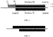
in the single-sided coating area, namely BC section area in surface M, the first coating layer including the first negative electrode active material layer is coated on a side surface of the negative electrode current collector; in the double-sided coating area, namely AB section area of the surface M and the ED section area of surface N, the second coating layers each including the first negative electrode active material layer and the second negative electrode active material layer are coated on both side surfaces of the negative electrode current collector, and the second negative electrode active material layer is coated on a surface of the negative electrode current collector, the first negative electrode active material layer is coated on a surface of the second negative electrode active material layer;
in a preparation process of the negative electrode sheet having the above-mentioned structure, a preparation of the surface M may be that, for example, a slurry forming the first negative electrode active material layer and a slurry forming the second negative electrode active material layer are coated altogether from end A of the negative electrode current collector, where the slurry forming the second negative electrode active material layer is close to the negative electrode current collector, the slurry forming the first negative electrode active material layer is away from the negative electrode current collector; the coating of the slurry forming the second negative electrode active material layer is ended at end B, the coating of the slurry forming the first negative electrode active material layer is kept and ended at end C to ensure that the thickness of the first coating layer of the single-sided coating area and the thicknesses of the second coating layers of the double-sided coating area are the same. - In the preparation process of the negative electrode sheet having the above structure, a preparation of the surface N may be that, for example, the slurry forming the first negative electrode active material layer and the slurry forming the second negative electrode active material layer are coated altogether from end E of the negative electrode current collector, where the slurry forming the second negative electrode active material layer is close to the negative electrode current collector, the slurry forming the first negative electrode active material layer is away from the negative electrode current collector; and the coating of the slurry forming the second negative electrode active material layer is ended at end D, or, the slurry forming the first negative electrode active material layer and the slurry forming the second negative electrode active material layer are coated altogether from end D of the negative electrode current collector, where the slurry forming the second negative electrode active material layer is close to the negative electrode current collector, the slurry forming the first negative electrode active material layer is away from the negative electrode current collector; and the coating of the slurry forming the second negative electrode active material layer is ended at end E; a line connecting end E and end A is perpendicular to the negative electrode current collector, in actual preparation process, there is a misalignment of about 0-1 mm between end E and end A, a line connecting end D and end B is perpendicular to the negative electrode current collector, in actual preparation process, there is a misalignment of about 0-1 mm between end D and end B, to ensure that of the tab area, the single-sided coating area and the double-sided coating area are formed in the negative electrode sheet.
- According to the present disclosure, the first negative electrode active material layer includes the first negative electrode active material, a first conductive agent and a first adhesive agent, the second negative electrode active material layer includes the second negative electrode active material, a second conductive agent and a second adhesive agent. The first negative electrode active material and the second negative electrode active material respectively forming the first negative electrode active material layer and the second negative electrode active material layer are the same or different, the first conductive agent and the second conductive agent are the same or different, and the first adhesive agent and the second adhesive agent are the same or different.
- According to the present disclosure, a mass percentage of each component in the first negative electrode active material layer is:
70-99 wt% of the first negative electrode active material, 0.5-15 wt% of the first conductive agent, and 0.5-15 wt% of the first adhesive agent; where a particle size distribution of the first negative electrode active material is: 3 µm < D10 < 4 µm, 5 µm < D50 < 8 µm, and 10 µm < D90 < 13 µm. - Preferably, the mass percentage of each component in the first negative electrode active material layer is:
80-98 wt% of the first negative electrode active material, 1-10 wt% of the first conductive agent, and 1-10 wt% of the first adhesive agent. - According to the present disclosure, a mass percentage of each component in the second negative electrode active material layer is:
70-99 wt% of the second negative electrode active material, 0.5-15 wt% of the second conductive agent, and 0.5-15 wt% of the second adhesive agent; where a particle size distribution of the second negative electrode active material is: 5 µm < D10 < 8 µm, 11 µm < D50 < 14 µm, and 20 µm < D90 < 25 µm. - Preferably, the mass percentage of each component in the second negative electrode active material layer is:
80-98 wt% of the second negative electrode active material, 1-10 wt% of the second conductive agent, and 1-10 wt% of the second adhesive agent. - The first conductive agent and the second conductive agent are the same or different, and are independently selected from at least one of conductive carbon black, acetylene black, Ketjen black, conductive graphite, conductive carbon fiber, carbon nanotube, metal powder, and carbon fiber.
- The first adhesive agent and the second adhesive agent are the same or different, and are independently selected from at least one of sodium carboxymethyl cellulose, styrene butadiene latex, polytetrafluoroethylene, and polyethylene oxide.
- The first negative electrode active material and the second negative electrode active material are the same or different, and are independently selected from at least one of artificial graphite, natural graphite, mesocarbon microspheres, and lithium titanate; preferably, the particle size distribution of the first negative electrode active material is: 3 µm < D10 <4 µm, 5 µm < D50 < 8 µm, 10 µm < D90 < 13 µm; the particle size distribution of the second negative electrode active material is: 5 µm < D10 <8 µm, 11 µm < D50 < 14 µm, 20 µm < D90 < 25 µm; and the particle size distribution of the first negative electrode active material is larger than that of the second negative electrode active material.
- The present disclosure further provides a preparation method of the above-mentioned negative electrode sheet, and the method includes the following steps:
- 1) preparing a slurry forming a first negative electrode active material layer and a slurry forming a second negative electrode active material layer, respectively;
- 2) using a double-layer coating machine to coat the slurry forming the first negative electrode active material layer and the slurry forming the second negative electrode active material layer on both side surfaces of a negative electrode current collector to prepare the negative electrode sheet.
- According to the present disclosure, in step 1), a solid content of the slurry forming the first negative electrode active material layer and the slurry forming the second negative electrode active material layer is 40 wt% to 45 wt%.
- According to the present disclosure, in step 2), on a side surface of the negative electrode current collector, the slurry forming the first negative electrode active material layer and the slurry forming the second negative electrode active material layer are coated altogether from end A of the negative electrode current collector, where the slurry forming the second negative electrode active material layer is close to the negative electrode current collector, the slurry forming the first negative electrode active material layer is away from the negative electrode current collector; the coating of the slurry forming the second negative electrode active material layer is ended at end B, the coating of the slurry forming the first negative electrode active material layer is kept and ended at end C, where an area between end A and end B is the double-sided coating area, an area between end B and end C is the single-sided coating area, the thickness of the first coating layer of the single-sided coating area and the thicknesses of the second coating layers of the double-sided coating area are the same.
- According to the present disclosure, in step 2), on the other side surface of the negative electrode current collector, the slurry forming the first negative electrode active material layer and the slurry forming the second negative electrode active material layer are coated altogether from end E of the negative electrode current collector, where the slurry forming the second negative electrode active material layer is close to the negative electrode current collector, the slurry forming the first negative electrode active material layer is away from the negative electrode current collector; and the coating of the slurry forming the second negative electrode active material layer is ended at end D, or, the slurry forming the first negative electrode active material layer and the slurry forming the second negative electrode active material layer are coated altogether from end D of the negative electrode current collector, where the slurry forming the second negative electrode active material layer is close to the negative electrode current collector, the slurry forming the first negative electrode active material layer is away from the negative electrode current collector; and the coating of the slurry forming the second negative electrode active material layer is ended at end E; a line connecting end E and end A is perpendicular to the negative electrode current collector, in actual preparation process, there is a misalignment of about 0-1 mm between end E and end A, a line connecting end D and end B is perpendicular to the negative electrode current collector, in actual preparation process, there is a misalignment of about 0-1 mm between end D and end B, to ensure that of the tab area, the single-sided coating area and the double-sided coating area are formed in the negative electrode sheet.
- The present disclosure further provides a lithium ion battery, including the above-mentioned negative electrode sheet.
- According to the present disclosure, the battery further includes a positive electrode sheet and a separator.
- The beneficial effects of the present disclosure are that:
the present disclosure provides a negative electrode sheet, a preparation method thereof and a lithium ion battery containing the same. The lithium ion battery containing the negative electrode sheet has the following effects: - (1) the problem of lithium deposition of a single-sided coating area of a negative electrode of a regular winding structural lithium ion battery can be effectively improved, thereby increasing a circulation lifetime of the lithium ion battery, and reducing a circulation inflation of the lithium ion battery;
- (2) a compaction density of a negative electrode can be increased and an energy density of a battery cell can be increased; and
- (3) a dynamic property of the negative electrode and a fast-charging capacity of the battery can be improved.
-
-
FIG. 1 is a structure of a negative electrode sheet according to a preferred embodiment of the present disclosure, where 1 is a first negative electrode active material layer, and 2 is a second negative electrode active material layer; and -
FIG. 2 is a structure of a regular negative electrode sheet. - The present disclosure will be further described in detail with reference to specific embodiments hereinafter. It should be understood that the following embodiments are only illustratively explicating and explaining the present disclosure, and should not be interpreted as limiting the protection scope of the present disclosure. All technologies implemented based on the foregoing contents of the present disclosure fall within the scope intended to protect by the present disclosure.
- The experiment methods used in the following embodiments are conventional methods unless otherwise specified; the reagents, materials, or the like, used in the following embodiments can be all obtained from commercial sources unless otherwise specified.
- In the description of the present disclosure, it should be noted that the terms "first", "second", or the like, are only used for descriptive purpose, and do not indicate or imply relative importance.
- The negative electrode sheet prepared in the following embodiments is used for a battery of model 386283, where a distance between a negative electrode tab disposed in a tab area and a single-sided coating area is 35.5±0.5 mm, and a length of the single-sided coating area is 113±2 mm, a length of a current collector is 885±2 mm, and a width of the current collector is 773±2 mm.
- The first step: prepare a slurry forming a first negative electrode active material layer: add a first negative electrode active material (artificial graphite), a first conductive agent (conductive carbon black) and a first adhesive agent (sodium carboxymethyl cellulose) into a stirring tank according to a mass ratio of 97:1.5:1.5, add deionized water to prepare the slurry forming the first negative electrode active material layer, a solid content of the negative electrode slurry is 40 wt% ~ 45 wt%; where a particle size distribution of the first negative electrode active material is: 3 µm < D10 < 4 µm, 5 µm < D50 < 8 µm, 10 µm < D90 < 13 µm.
- The second step: prepare a slurry forming a second negative electrode active material layer: add a second negative electrode active material (artificial graphite), a second conductive agent (conductive carbon black) and a second adhesive agent (sodium carboxymethyl cellulose) into a stirring tank according to a mass ratio of 97:1.5:1.5, add deionized water to prepare the slurry forming the second negative electrode active material layer, a solid content of the negative electrode slurry is 40 wt% to 45 wt%; where the particle size distribution of the second negative electrode active material is: 5 µm < D10 < 8 µm, 11 µm < D50 < 14 µm, 20 µm < D90 < 2 5 µm.
- The third step: use a double-layer coating machine to coat the slurry forming the first negative electrode active material layer and the slurry forming the second negative electrode active material layer on surfaces of the negative electrode current collector, specifically:
- as shown in
FIG. 1 , on a side surface M of the negative electrode current collector, the slurry forming the first negative electrode active material layer and the slurry forming the second negative electrode active material layer are coated altogether from end A of the negative electrode current collector, where the slurry forming the second negative electrode active material layer is close to the negative electrode current collector, the slurry forming the first negative electrode active material layer is away from the negative electrode current collector; the coating of the slurry forming the second negative electrode active material layer is ended at end B, the coating of the slurry forming the first negative electrode active material layer is kept and ended at end C, where an area between end A and end B is the double-sided coating area, an area between end B and end C is the single-sided coating area, the thickness of the first coating layer of the single-sided coating area and the thicknesses of the second coating layers of the double-sided coating area are the same; - on the other side surface N of the negative electrode current collector, the slurry forming the first negative electrode active material layer and the slurry forming the second negative electrode active material layer are coated altogether from end E of the negative electrode current collector, where the slurry forming the second negative electrode active material layer is close to the negative electrode current collector, the slurry forming the first negative electrode active material layer is away from the negative electrode current collector; and the coating of the slurry forming the second negative electrode active material layer is ended at end D, or, the slurry forming the first negative electrode active material layer and the slurry forming the second negative electrode active material layer are coated altogether from end D of the negative electrode current collector, where the slurry forming the second negative electrode active material layer is close to the negative electrode current collector, the slurry forming the first negative electrode active material layer is away from the negative electrode current collector; and the coating of the slurry forming the second negative electrode active material layer is ended at end E; a line connecting end E and end A is perpendicular to the negative electrode current collector, a line connecting end D and end B is perpendicular to the negative electrode current collector, to ensure that of the tab area, the single-sided coating area and the double-sided coating area are formed in the negative electrode sheet; the prepared negative electrode sheet is dried at a temperature of 100°C.
- The fourth step: prepare a positive electrode sheet: use lithium cobalt oxide as a positive electrode active material, and then add it along with a conductive agent (acetylene black) and an adhesive agent (polyvinylidene fluoride) into a stirring tank according to a mass ratio of 97.2:1.5:1.3, add NMP solvent, stir well, go through a 200-mesh screen to obtain a positive electrode slurry, where a solid content of the positive electrode slurry is 70 wt% ~ 75 wt%, and then use a coating machine to coat the slurry on an aluminum foil, dry it at 120 °C to obtain the positive electrode sheet.
- The fifth step: assemble a battery cell: wind the negative electrode sheet prepared in the first to third steps above, the positive electrode sheet prepared in the fourth step and a separator together to form a roll core, which is packaged with an aluminum plastic film, baked to remove moisture and then injected with electrolytic solution, and applied with a hot-press forming process to form the battery cell.
- The other operation steps are the same as
Embodiment 1, the only difference lies in that the thickness of the single-sided coating area, and the thicknesses of the first negative electrode active material layer and the second negative electrode active material layer of the double-sided coating area are different, which is specifically shown in Table 1.Table 1 Structural parameters of the negative electrode sheet of Embodiments 1-3 and Comparative Examples 1-2 Double-sided coating area Single-sided coating area The thickness of the first negative electrode active material layer The thickness of the second negative electrode active material layer Embodiment 1 5 µm 115 µm First negative electrode active material layer 120 µm Embodiment 2 15 µm 105 µm First negative electrode active material layer 120 µm Embodiment 3 30 µm 90 µm First negative electrode active material layer 120 µm Comparative Example 1 0 120 µm First negative electrode active material layer 120 µm Comparative Example 2 120 µm 0 First negative electrode active material layer 120 µm - The negative electrode sheets prepared in the embodiments have the same compaction density, and assembled into a soft-packed battery cell of model 386283. An energy density is tested by charging and discharging with 0.2C/0.2C at 25°C, each of the prepared soft-packed battery cell is charged with 2.5C or discharged with 0.7C at 25°C, and the battery is disassembled under different circulation counts to confirm a lithium deposition of the single-sided coating area of the negative electrode of the battery and the negative electrode surface. The disassembling result and energy density are shown in Table 2 below.
Table 2 The energy density of the battery and the lithium deposition, capacity retention rate and inflation data of the single-sided coating area of the negative electrode during a cycling process of the embodiments Items Energy Density Wh/L Lithium Deposition 1000T Capacity Retention Rate 1000T Inflation 300T Single-sided coating area 500T Single-sided coating area 1000T Single-sided coating area 300T Negative Electrode Surface 500T Negative Electrode Surface 1000T Negative Electrode Surface Embodiment 1 693 No Lithium Deposition No Lithium Deposition No Lithium Deposition No Lithium Deposition No Lithium Deposition Slight Lithium Deposition 83.01% 9.85 % Embodiment 2 692 No Lithium Deposition No Lithium Deposition No Lithium Deposition No Lithium Deposition No Lithium Deposition No Lithium Deposition 84.32% 9.63% Embodiment 3 689 No Lithium Deposition No Lithium Deposition No Lithium Deposition No Lithium Deposition No Lithium Deposition No Lithium Deposition 86.09% 9.01% Comparative Example 1 690 Slight Lithium Deposition Lithium Deposition Severe Lithium Deposition No Lithium Deposition Slight Lithium Deposition Lithium Deposition 80.23% 11.15% Comparative Example 2 675 No Lithium Deposition No Lithium Deposition No Lithium Deposition No Lithium Deposition No Lithium Deposition No Lithium Deposition 87.35% 8.95% - In Table 2, the single-sided coating area has slight lithium deposition indicates that the single-sided coating area has a lithium deposition area takes up less than 10% of a total area of the single-sided coating area; the single-sided coating area has lithium deposition indicates that the lithium deposition area of the single-sided coating area takes up 10%~30% of the total area of the single-sided coating area; the single-sided coating area has severe lithium deposition indicates that the lithium deposition area of the single-sided coating area takes up greater than 50% of the total area of the single-sided coating area;
the negative electrode surface has slight lithium deposition indicates that a lithium deposition area takes up less than 10% of a total area of the negative electrode; the negative electrode surface has lithium deposition indicates that the lithium deposition area takes up 10% to 30% of the total area of the negative electrode; the negative electrode surface has severe lithium deposition indicates that lithium deposition area takes up more than 50% of the total area of the negative electrode. - It can be seen from Table 2 that the battery cell prepared using the method of the present disclosure can effectively improve the problem of lithium deposition of the single-sided coating area of the negative electrode of the conventional winding structural lithium ion battery without reducing the energy density of the battery, improve the circulation lifetime of the lithium ion battery, improve the circulation inflation, and improve the fast-charging performance of the lithium-ion battery. Although mere use of a negative electrode active material with better dynamic property and smaller particle size can effectively improve the problem of lithium deposition of the single-sided coating area of the negative electrode during long circulation process, it greatly reduces its energy density.
- The implementations of the present disclosure have been illustrated above. However, the present disclosure is not limited to the above-mentioned implementations. Any modification, equivalent replacement, improvement, or the like, made within the spirit and the principle of the present disclosure shall fall within the protection scope of the present disclosure.
Claims (9)
- A winding negative electrode sheet, comprising a negative electrode current collector, wherein the negative electrode current collector comprises a single-sided coating area and a double-sided coating area;
in the single-sided coating area, a first coating layer is disposed on a side surface of the negative electrode current collector and comprises a first negative electrode active material layer (1);
in the double-sided coating area, second coating layers are disposed on both side surfaces of the negative electrode current collector, respectively, wherein each of the second coating layers comprises a first negative electrode active material layer (1) and a second negative electrode active material layer (2), the second negative electrode active material layer (2) is disposed on a surface of the negative electrode current collector, and the first negative electrode active material layer (1) is disposed on a surface of the second negative electrode active material layer (2);
the first negative electrode active material layer (1) comprises a first negative electrode active material, the second negative electrode active material layer (2) comprises a second negative electrode active material, and a reception speed of lithium ions of the first negative electrode active material is greater than a reception speed of lithium ions of the second negative electrode active material. - The negative electrode sheet according to claim 1, wherein a particle size distribution of the first negative electrode active material forming the first negative electrode active material layer (1) is: 3 µm < D10 < 4 µm, 5 µm < D50 < 8 µm, 10 µm < D90 < 13 µm; a particle size distribution of the second negative electrode active material forming the second negative electrode active material layer (2) is: 5 µm < D10 < 8 µm, 11 µm < D50 < 14 µm, 20 µm < D90 < 25 µm.
- The negative electrode sheet according to claim 1 or 2, wherein the first negative electrode active material layer (1) of the first coating layer is connected to the first negative electrode active material layer (1) of the second coating layer.
- The negative electrode sheet according to any one of claims 1 to 3, wherein a thickness of the first coating layer and thicknesses of the second coating layers are the same.
- The negative electrode sheet according to any one of claims 1 to 4, wherein in the double-sided coating area, thicknesses of the second coating layers on both sides of the negative electrode current collector are the same.
- The negative electrode sheet according to any one of claims 1 to 5, wherein in the second coating layers, a thickness of the first negative electrode active material layer (1) is 5-30 µm, a thickness of the second negative electrode active material layer (2) is 90-115 µm; and a sum of the thickness of the first negative electrode active material layer (1) and the thickness of the second negative electrode active material layer (2) is 95-120 µm.
- The negative electrode sheet according to any one of claims 1 to 6, wherein the first negative electrode active material layer (1) further comprises a first conductive agent and a first adhesive agent;
a mass percentage of each component in the first negative electrode active material layer (1) is:
70-99 wt% of the first negative electrode active material, 0.5-15 wt% of the first conductive agent, and 0.5-15 wt% of the first adhesive agent;
wherein, a particle size distribution of the first negative electrode active material is: 3 µm < D10< 4 µm, 5 µm < D50 < 8 µm, and 10 µm < D90< 13 µm. - The negative electrode sheet according to any one of claims 1 to 7, wherein the second negative electrode active material layer (2) further comprises a second conductive agent and a second adhesive agent;
a mass percentage of each component in the second negative electrode active material layer (2) is:
70-99 wt% of the second negative electrode active material, 0.5-15 wt% of the second conductive agent, and 0.5-15 wt% of the second adhesive agent;
wherein a particle size distribution of the second negative electrode active material is: 5 µm < D10 < 8 µm, 11 µm < D50 < 14 µm, and 20 µm < D90 < 25 µm. - A lithium-ion battery, comprising the negative electrode sheet according to any one of claims 1 to 8.
Applications Claiming Priority (1)
| Application Number | Priority Date | Filing Date | Title |
|---|---|---|---|
| CN202010383944.7A CN111540881B (en) | 2020-05-08 | 2020-05-08 | A kind of negative electrode sheet, preparation method and lithium ion battery including the same |
Publications (2)
| Publication Number | Publication Date |
|---|---|
| EP3907800A1 true EP3907800A1 (en) | 2021-11-10 |
| EP3907800B1 EP3907800B1 (en) | 2023-02-08 |
Family
ID=71977544
Family Applications (1)
| Application Number | Title | Priority Date | Filing Date |
|---|---|---|---|
| EP20214605.6A Active EP3907800B1 (en) | 2020-05-08 | 2020-12-16 | Negative electrode sheet, preparation method thereof and lithium ion battery containing the same |
Country Status (3)
| Country | Link |
|---|---|
| US (1) | US11522168B2 (en) |
| EP (1) | EP3907800B1 (en) |
| CN (2) | CN113410432B (en) |
Families Citing this family (20)
| Publication number | Priority date | Publication date | Assignee | Title |
|---|---|---|---|---|
| CN112103463B (en) * | 2020-09-14 | 2022-03-29 | 珠海冠宇动力电池有限公司 | A negative pole piece and a lithium ion battery comprising the negative pole piece |
| EP4138154A4 (en) | 2020-10-15 | 2024-03-06 | Contemporary Amperex Technology Co., Limited | SECONDARY BATTERY, PREPARATION METHOD THEREFOR, BATTERY MODULE INCLUDING SAME, BATTERY PACK AND DEVICE |
| CN112635717B (en) * | 2020-12-18 | 2022-08-19 | 珠海冠宇电池股份有限公司 | Pole piece, battery and manufacturing method of pole piece |
| KR102543843B1 (en) | 2020-12-28 | 2023-06-14 | 컨템포러리 엠퍼렉스 테크놀로지 씨오., 리미티드 | Anode electrode plate and its manufacturing method, secondary battery, battery module, battery pack and device |
| CN112736218B (en) * | 2020-12-29 | 2022-10-21 | 珠海冠宇电池股份有限公司 | Lithium battery negative plate, winding type battery cell and lithium ion battery |
| CN112750976B (en) * | 2020-12-29 | 2022-08-23 | 珠海冠宇电池股份有限公司 | Lithium battery core and lithium ion battery |
| CN112701250A (en) * | 2020-12-29 | 2021-04-23 | 珠海冠宇电池股份有限公司 | Lithium ion battery |
| CN112820852B (en) * | 2020-12-30 | 2022-04-15 | 珠海冠宇电池股份有限公司 | Negative plate and lithium ion battery |
| CN113097427A (en) * | 2021-03-30 | 2021-07-09 | 珠海冠宇电池股份有限公司 | Negative plate and battery |
| CN113097428A (en) * | 2021-03-30 | 2021-07-09 | 珠海冠宇电池股份有限公司 | Negative plate, battery and preparation method of negative plate |
| HUE070435T2 (en) * | 2021-04-22 | 2025-06-28 | Contemporary Amperex Technology Hong Kong Ltd | Electrode assembly and manufacturing method and manufacturing system therefor, battery cell, and battery |
| CN113675365B (en) * | 2021-09-01 | 2023-11-24 | 珠海冠宇电池股份有限公司 | A kind of negative electrode sheet and lithium-ion battery |
| CN113839084A (en) * | 2021-09-29 | 2021-12-24 | 珠海冠宇电池股份有限公司 | Battery core and battery |
| CN114094076B (en) * | 2021-11-15 | 2023-10-13 | 珠海冠宇电池股份有限公司 | A negative electrode sheet and a lithium-ion battery including the negative electrode sheet |
| CN114094046A (en) * | 2021-11-22 | 2022-02-25 | 珠海冠宇电池股份有限公司 | Lithium ion battery and electronic device |
| CN114242936B (en) * | 2021-12-16 | 2024-01-30 | 珠海冠宇电池股份有限公司 | Electrode assembly and application thereof |
| CN114464771B (en) * | 2022-02-09 | 2024-07-16 | 珠海冠宇电池股份有限公司 | A battery cell |
| CN114551980B (en) * | 2022-02-28 | 2024-08-20 | 宁德新能源科技有限公司 | Electrochemical devices and electronic devices |
| EP4258404A4 (en) * | 2022-02-28 | 2024-05-08 | Ningde Amperex Technology Ltd. | ELECTROCHEMICAL DEVICE AND ELECTRONIC DEVICE |
| KR20240112609A (en) * | 2023-01-12 | 2024-07-19 | 에스케이온 주식회사 | Negative electrode, kit for manufacturing negative electrode mixture layer, and method for manufacturing negative electrode |
Citations (4)
| Publication number | Priority date | Publication date | Assignee | Title |
|---|---|---|---|---|
| US20140141303A1 (en) * | 2012-11-16 | 2014-05-22 | Sony Corporation | Battery, battery pack, electronic apparatus, electric vehicle, electric power storage apparatus, and electric power system |
| US20180287145A1 (en) * | 2016-07-04 | 2018-10-04 | Lg Chem, Ltd. | Negative electrode for secondary battery |
| CN110534701A (en) * | 2019-08-06 | 2019-12-03 | 荣盛盟固利新能源科技有限公司 | A kind of electrode plates, electrode plates manufacturing method and electrochemical appliance |
| CN110581254A (en) * | 2019-10-16 | 2019-12-17 | 珠海冠宇电池有限公司 | Lithium ion battery cathode and preparation method thereof |
Family Cites Families (16)
| Publication number | Priority date | Publication date | Assignee | Title |
|---|---|---|---|---|
| US20120009475A1 (en) * | 2010-03-15 | 2012-01-12 | Kensuke Nakura | Electrode for non-aqueous electrolyte secondary battery and non-aqueous electrolyte secondary battery including the same |
| JP2013149403A (en) * | 2012-01-18 | 2013-08-01 | Hitachi Ltd | Lithium ion secondary battery negative electrode, lithium ion secondary battery electrode using the same, and manufacturing method thereof |
| JP5962961B2 (en) * | 2012-03-27 | 2016-08-03 | トヨタ自動車株式会社 | Positive electrode, manufacturing method thereof, and nonaqueous electrolyte secondary battery using the positive electrode |
| CN103579666B (en) * | 2013-11-04 | 2016-02-03 | 维动新能源股份有限公司 | A kind of low internal resistance compound lithium ion battery core and manufacture craft thereof |
| KR20170109293A (en) * | 2016-03-21 | 2017-09-29 | 주식회사 엘지화학 | Negative electrode and secondary battery |
| CN205828572U (en) * | 2016-06-24 | 2016-12-21 | 宁德时代新能源科技股份有限公司 | wound battery |
| KR102354357B1 (en) * | 2016-12-09 | 2022-01-20 | 삼성에스디아이 주식회사 | Rechargeable battery |
| CN106848325B (en) * | 2017-02-15 | 2020-09-15 | 宁德时代新能源科技股份有限公司 | Secondary battery pole piece, preparation method thereof and winding type battery cell |
| CN108306052B (en) * | 2018-03-06 | 2024-02-09 | 深圳前海优容科技有限公司 | Battery cell, manufacturing method thereof, battery and electronic device |
| WO2019239988A1 (en) * | 2018-06-11 | 2019-12-19 | 株式会社村田製作所 | Battery electrode and manufacturing method therefor |
| JP7237296B2 (en) * | 2018-07-03 | 2023-03-13 | 川上 総一郎 | storage device |
| JP7073947B2 (en) | 2018-07-05 | 2022-05-24 | トヨタ自動車株式会社 | Information processing equipment, information processing methods, and programs |
| KR102165952B1 (en) * | 2018-09-13 | 2020-10-14 | 한국기계연구원 | An Anode for Secondary battery and Fabricating Method of the same |
| CN109244362B (en) * | 2018-11-05 | 2023-11-03 | 宁德新能源科技有限公司 | Positive electrode plate, electrochemical device and electronic device containing the same |
| CN209843876U (en) * | 2019-05-20 | 2019-12-24 | 惠州市豪鹏科技有限公司 | Winding type battery cell and lithium ion battery |
| CN113299877B (en) * | 2019-12-11 | 2023-03-24 | 宁德新能源科技有限公司 | Negative electrode, and electrochemical device and electronic device including the same |
-
2020
- 2020-05-08 CN CN202110634246.4A patent/CN113410432B/en active Active
- 2020-05-08 CN CN202010383944.7A patent/CN111540881B/en active Active
- 2020-12-11 US US17/119,304 patent/US11522168B2/en active Active
- 2020-12-16 EP EP20214605.6A patent/EP3907800B1/en active Active
Patent Citations (4)
| Publication number | Priority date | Publication date | Assignee | Title |
|---|---|---|---|---|
| US20140141303A1 (en) * | 2012-11-16 | 2014-05-22 | Sony Corporation | Battery, battery pack, electronic apparatus, electric vehicle, electric power storage apparatus, and electric power system |
| US20180287145A1 (en) * | 2016-07-04 | 2018-10-04 | Lg Chem, Ltd. | Negative electrode for secondary battery |
| CN110534701A (en) * | 2019-08-06 | 2019-12-03 | 荣盛盟固利新能源科技有限公司 | A kind of electrode plates, electrode plates manufacturing method and electrochemical appliance |
| CN110581254A (en) * | 2019-10-16 | 2019-12-17 | 珠海冠宇电池有限公司 | Lithium ion battery cathode and preparation method thereof |
Also Published As
| Publication number | Publication date |
|---|---|
| CN113410432B (en) | 2022-05-27 |
| US20210351392A1 (en) | 2021-11-11 |
| CN113410432A (en) | 2021-09-17 |
| CN111540881A (en) | 2020-08-14 |
| CN111540881B (en) | 2021-07-06 |
| EP3907800B1 (en) | 2023-02-08 |
| US11522168B2 (en) | 2022-12-06 |
Similar Documents
| Publication | Publication Date | Title |
|---|---|---|
| EP3907800B1 (en) | Negative electrode sheet, preparation method thereof and lithium ion battery containing the same | |
| US20230118023A1 (en) | Positive electrode sheet, preparation method thereof, and lithium-ion battery including the positive electrode sheet | |
| US20220367878A1 (en) | Positive electrode sheet, preparation method thereof, and lithium-ion battery including the positive electrode sheet | |
| EP4131475B1 (en) | Electrode for rechargeable lithium battery and rechargeable lithium battery including the same | |
| US20230187606A1 (en) | Negative electrode piece, preparation method thereof and lithium-ion battery including same | |
| CN113097441B (en) | Electrochemical device and electronic device | |
| CN113675372B (en) | Electrochemical device and electronic device | |
| EP4156319A1 (en) | High-load electrode, preparation method therefor, and lithium ion battery thereof | |
| CN111540880B (en) | Negative plate, preparation method and lithium ion battery comprising negative plate | |
| EP3886218A1 (en) | Negative electrode plate, electrochemical device, and electronic device | |
| CN111009682B (en) | All-solid-state battery and preparation method thereof | |
| CN111916666B (en) | A negative electrode sheet with a special-shaped structure and a lithium ion battery comprising the negative electrode sheet | |
| CN112186273B (en) | A winding core for a wound lithium-ion battery capable of reducing internal temperature rise | |
| EP3573145A1 (en) | Battery and method for preparing the same | |
| CN110224182A (en) | A kind of method of lithium ion battery pre-lithiation | |
| CN116230860A (en) | A kind of sulfur-based solid electrolyte composite oxide cathode material and its preparation method and application | |
| EP4131508A1 (en) | Pole piece, cell and battery | |
| CN119252920A (en) | A double-layer coated lithium supplement agent and its preparation method and application | |
| EP4645472A1 (en) | Electrode, secondary battery, and electronic device | |
| CN116207368A (en) | Ultralow-temperature lithium iron phosphate battery and processing preparation method thereof | |
| EP4715852A1 (en) | Capacitor electrode sheet and preparation method therefor, and capacitor using same | |
| EP4675745A1 (en) | Electrochemical apparatus and electronic apparatus | |
| EP4224547A1 (en) | Negative electrode, method of manufacturing negative electrode, and secondary battery including negative electrode | |
| EP4564456A1 (en) | Secondary battery, preparation method therefor, and electric device | |
| EP4641696A1 (en) | Electrode, secondary battery, and electric device |
Legal Events
| Date | Code | Title | Description |
|---|---|---|---|
| PUAI | Public reference made under article 153(3) epc to a published international application that has entered the european phase |
Free format text: ORIGINAL CODE: 0009012 |
|
| STAA | Information on the status of an ep patent application or granted ep patent |
Free format text: STATUS: REQUEST FOR EXAMINATION WAS MADE |
|
| 17P | Request for examination filed |
Effective date: 20201216 |
|
| AK | Designated contracting states |
Kind code of ref document: A1 Designated state(s): AL AT BE BG CH CY CZ DE DK EE ES FI FR GB GR HR HU IE IS IT LI LT LU LV MC MK MT NL NO PL PT RO RS SE SI SK SM TR |
|
| B565 | Issuance of search results under rule 164(2) epc |
Effective date: 20210520 |
|
| STAA | Information on the status of an ep patent application or granted ep patent |
Free format text: STATUS: EXAMINATION IS IN PROGRESS |
|
| 17Q | First examination report despatched |
Effective date: 20211123 |
|
| GRAP | Despatch of communication of intention to grant a patent |
Free format text: ORIGINAL CODE: EPIDOSNIGR1 |
|
| STAA | Information on the status of an ep patent application or granted ep patent |
Free format text: STATUS: GRANT OF PATENT IS INTENDED |
|
| INTG | Intention to grant announced |
Effective date: 20220708 |
|
| GRAS | Grant fee paid |
Free format text: ORIGINAL CODE: EPIDOSNIGR3 |
|
| GRAA | (expected) grant |
Free format text: ORIGINAL CODE: 0009210 |
|
| STAA | Information on the status of an ep patent application or granted ep patent |
Free format text: STATUS: THE PATENT HAS BEEN GRANTED |
|
| AK | Designated contracting states |
Kind code of ref document: B1 Designated state(s): AL AT BE BG CH CY CZ DE DK EE ES FI FR GB GR HR HU IE IS IT LI LT LU LV MC MK MT NL NO PL PT RO RS SE SI SK SM TR |
|
| REG | Reference to a national code |
Ref country code: GB Ref legal event code: FG4D |
|
| REG | Reference to a national code |
Ref country code: CH Ref legal event code: EP Ref country code: AT Ref legal event code: REF Ref document number: 1547665 Country of ref document: AT Kind code of ref document: T Effective date: 20230215 |
|
| REG | Reference to a national code |
Ref country code: IE Ref legal event code: FG4D |
|
| REG | Reference to a national code |
Ref country code: DE Ref legal event code: R096 Ref document number: 602020007986 Country of ref document: DE |
|
| REG | Reference to a national code |
Ref country code: LT Ref legal event code: MG9D |
|
| REG | Reference to a national code |
Ref country code: NL Ref legal event code: MP Effective date: 20230208 |
|
| REG | Reference to a national code |
Ref country code: AT Ref legal event code: MK05 Ref document number: 1547665 Country of ref document: AT Kind code of ref document: T Effective date: 20230208 |
|
| PG25 | Lapsed in a contracting state [announced via postgrant information from national office to epo] |
Ref country code: RS Free format text: LAPSE BECAUSE OF FAILURE TO SUBMIT A TRANSLATION OF THE DESCRIPTION OR TO PAY THE FEE WITHIN THE PRESCRIBED TIME-LIMIT Effective date: 20230208 Ref country code: PT Free format text: LAPSE BECAUSE OF FAILURE TO SUBMIT A TRANSLATION OF THE DESCRIPTION OR TO PAY THE FEE WITHIN THE PRESCRIBED TIME-LIMIT Effective date: 20230609 Ref country code: NO Free format text: LAPSE BECAUSE OF FAILURE TO SUBMIT A TRANSLATION OF THE DESCRIPTION OR TO PAY THE FEE WITHIN THE PRESCRIBED TIME-LIMIT Effective date: 20230508 Ref country code: NL Free format text: LAPSE BECAUSE OF FAILURE TO SUBMIT A TRANSLATION OF THE DESCRIPTION OR TO PAY THE FEE WITHIN THE PRESCRIBED TIME-LIMIT Effective date: 20230208 Ref country code: LV Free format text: LAPSE BECAUSE OF FAILURE TO SUBMIT A TRANSLATION OF THE DESCRIPTION OR TO PAY THE FEE WITHIN THE PRESCRIBED TIME-LIMIT Effective date: 20230208 Ref country code: LT Free format text: LAPSE BECAUSE OF FAILURE TO SUBMIT A TRANSLATION OF THE DESCRIPTION OR TO PAY THE FEE WITHIN THE PRESCRIBED TIME-LIMIT Effective date: 20230208 Ref country code: HR Free format text: LAPSE BECAUSE OF FAILURE TO SUBMIT A TRANSLATION OF THE DESCRIPTION OR TO PAY THE FEE WITHIN THE PRESCRIBED TIME-LIMIT Effective date: 20230208 Ref country code: ES Free format text: LAPSE BECAUSE OF FAILURE TO SUBMIT A TRANSLATION OF THE DESCRIPTION OR TO PAY THE FEE WITHIN THE PRESCRIBED TIME-LIMIT Effective date: 20230208 Ref country code: AT Free format text: LAPSE BECAUSE OF FAILURE TO SUBMIT A TRANSLATION OF THE DESCRIPTION OR TO PAY THE FEE WITHIN THE PRESCRIBED TIME-LIMIT Effective date: 20230208 |
|
| PG25 | Lapsed in a contracting state [announced via postgrant information from national office to epo] |
Ref country code: SE Free format text: LAPSE BECAUSE OF FAILURE TO SUBMIT A TRANSLATION OF THE DESCRIPTION OR TO PAY THE FEE WITHIN THE PRESCRIBED TIME-LIMIT Effective date: 20230208 Ref country code: PL Free format text: LAPSE BECAUSE OF FAILURE TO SUBMIT A TRANSLATION OF THE DESCRIPTION OR TO PAY THE FEE WITHIN THE PRESCRIBED TIME-LIMIT Effective date: 20230208 Ref country code: IS Free format text: LAPSE BECAUSE OF FAILURE TO SUBMIT A TRANSLATION OF THE DESCRIPTION OR TO PAY THE FEE WITHIN THE PRESCRIBED TIME-LIMIT Effective date: 20230608 Ref country code: GR Free format text: LAPSE BECAUSE OF FAILURE TO SUBMIT A TRANSLATION OF THE DESCRIPTION OR TO PAY THE FEE WITHIN THE PRESCRIBED TIME-LIMIT Effective date: 20230509 Ref country code: FI Free format text: LAPSE BECAUSE OF FAILURE TO SUBMIT A TRANSLATION OF THE DESCRIPTION OR TO PAY THE FEE WITHIN THE PRESCRIBED TIME-LIMIT Effective date: 20230208 |
|
| PG25 | Lapsed in a contracting state [announced via postgrant information from national office to epo] |
Ref country code: SM Free format text: LAPSE BECAUSE OF FAILURE TO SUBMIT A TRANSLATION OF THE DESCRIPTION OR TO PAY THE FEE WITHIN THE PRESCRIBED TIME-LIMIT Effective date: 20230208 Ref country code: RO Free format text: LAPSE BECAUSE OF FAILURE TO SUBMIT A TRANSLATION OF THE DESCRIPTION OR TO PAY THE FEE WITHIN THE PRESCRIBED TIME-LIMIT Effective date: 20230208 Ref country code: EE Free format text: LAPSE BECAUSE OF FAILURE TO SUBMIT A TRANSLATION OF THE DESCRIPTION OR TO PAY THE FEE WITHIN THE PRESCRIBED TIME-LIMIT Effective date: 20230208 Ref country code: DK Free format text: LAPSE BECAUSE OF FAILURE TO SUBMIT A TRANSLATION OF THE DESCRIPTION OR TO PAY THE FEE WITHIN THE PRESCRIBED TIME-LIMIT Effective date: 20230208 Ref country code: CZ Free format text: LAPSE BECAUSE OF FAILURE TO SUBMIT A TRANSLATION OF THE DESCRIPTION OR TO PAY THE FEE WITHIN THE PRESCRIBED TIME-LIMIT Effective date: 20230208 |
|
| REG | Reference to a national code |
Ref country code: DE Ref legal event code: R097 Ref document number: 602020007986 Country of ref document: DE |
|
| PG25 | Lapsed in a contracting state [announced via postgrant information from national office to epo] |
Ref country code: SK Free format text: LAPSE BECAUSE OF FAILURE TO SUBMIT A TRANSLATION OF THE DESCRIPTION OR TO PAY THE FEE WITHIN THE PRESCRIBED TIME-LIMIT Effective date: 20230208 |
|
| PLBE | No opposition filed within time limit |
Free format text: ORIGINAL CODE: 0009261 |
|
| STAA | Information on the status of an ep patent application or granted ep patent |
Free format text: STATUS: NO OPPOSITION FILED WITHIN TIME LIMIT |
|
| 26N | No opposition filed |
Effective date: 20231109 |
|
| PG25 | Lapsed in a contracting state [announced via postgrant information from national office to epo] |
Ref country code: SI Free format text: LAPSE BECAUSE OF FAILURE TO SUBMIT A TRANSLATION OF THE DESCRIPTION OR TO PAY THE FEE WITHIN THE PRESCRIBED TIME-LIMIT Effective date: 20230208 |
|
| REG | Reference to a national code |
Ref country code: CH Ref legal event code: PL |
|
| PG25 | Lapsed in a contracting state [announced via postgrant information from national office to epo] |
Ref country code: LU Free format text: LAPSE BECAUSE OF NON-PAYMENT OF DUE FEES Effective date: 20231216 |
|
| PG25 | Lapsed in a contracting state [announced via postgrant information from national office to epo] |
Ref country code: MC Free format text: LAPSE BECAUSE OF FAILURE TO SUBMIT A TRANSLATION OF THE DESCRIPTION OR TO PAY THE FEE WITHIN THE PRESCRIBED TIME-LIMIT Effective date: 20230208 |
|
| REG | Reference to a national code |
Ref country code: BE Ref legal event code: MM Effective date: 20231231 |
|
| PG25 | Lapsed in a contracting state [announced via postgrant information from national office to epo] |
Ref country code: MC Free format text: LAPSE BECAUSE OF FAILURE TO SUBMIT A TRANSLATION OF THE DESCRIPTION OR TO PAY THE FEE WITHIN THE PRESCRIBED TIME-LIMIT Effective date: 20230208 Ref country code: LU Free format text: LAPSE BECAUSE OF NON-PAYMENT OF DUE FEES Effective date: 20231216 |
|
| REG | Reference to a national code |
Ref country code: IE Ref legal event code: MM4A |
|
| PG25 | Lapsed in a contracting state [announced via postgrant information from national office to epo] |
Ref country code: IE Free format text: LAPSE BECAUSE OF NON-PAYMENT OF DUE FEES Effective date: 20231216 |
|
| PG25 | Lapsed in a contracting state [announced via postgrant information from national office to epo] |
Ref country code: BE Free format text: LAPSE BECAUSE OF NON-PAYMENT OF DUE FEES Effective date: 20231231 |
|
| PG25 | Lapsed in a contracting state [announced via postgrant information from national office to epo] |
Ref country code: CH Free format text: LAPSE BECAUSE OF NON-PAYMENT OF DUE FEES Effective date: 20231231 |
|
| PG25 | Lapsed in a contracting state [announced via postgrant information from national office to epo] |
Ref country code: IE Free format text: LAPSE BECAUSE OF NON-PAYMENT OF DUE FEES Effective date: 20231216 Ref country code: CH Free format text: LAPSE BECAUSE OF NON-PAYMENT OF DUE FEES Effective date: 20231231 Ref country code: BE Free format text: LAPSE BECAUSE OF NON-PAYMENT OF DUE FEES Effective date: 20231231 |
|
| PG25 | Lapsed in a contracting state [announced via postgrant information from national office to epo] |
Ref country code: BG Free format text: LAPSE BECAUSE OF FAILURE TO SUBMIT A TRANSLATION OF THE DESCRIPTION OR TO PAY THE FEE WITHIN THE PRESCRIBED TIME-LIMIT Effective date: 20230208 |
|
| PG25 | Lapsed in a contracting state [announced via postgrant information from national office to epo] |
Ref country code: BG Free format text: LAPSE BECAUSE OF FAILURE TO SUBMIT A TRANSLATION OF THE DESCRIPTION OR TO PAY THE FEE WITHIN THE PRESCRIBED TIME-LIMIT Effective date: 20230208 |
|
| PG25 | Lapsed in a contracting state [announced via postgrant information from national office to epo] |
Ref country code: CY Free format text: LAPSE BECAUSE OF FAILURE TO SUBMIT A TRANSLATION OF THE DESCRIPTION OR TO PAY THE FEE WITHIN THE PRESCRIBED TIME-LIMIT; INVALID AB INITIO Effective date: 20201216 |
|
| PG25 | Lapsed in a contracting state [announced via postgrant information from national office to epo] |
Ref country code: HU Free format text: LAPSE BECAUSE OF FAILURE TO SUBMIT A TRANSLATION OF THE DESCRIPTION OR TO PAY THE FEE WITHIN THE PRESCRIBED TIME-LIMIT; INVALID AB INITIO Effective date: 20201216 |
|
| PG25 | Lapsed in a contracting state [announced via postgrant information from national office to epo] |
Ref country code: TR Free format text: LAPSE BECAUSE OF FAILURE TO SUBMIT A TRANSLATION OF THE DESCRIPTION OR TO PAY THE FEE WITHIN THE PRESCRIBED TIME-LIMIT Effective date: 20230208 |
|
| PGFP | Annual fee paid to national office [announced via postgrant information from national office to epo] |
Ref country code: DE Payment date: 20251212 Year of fee payment: 6 |
|
| PGFP | Annual fee paid to national office [announced via postgrant information from national office to epo] |
Ref country code: GB Payment date: 20251211 Year of fee payment: 6 |
|
| PGFP | Annual fee paid to national office [announced via postgrant information from national office to epo] |
Ref country code: IT Payment date: 20251212 Year of fee payment: 6 |
|
| PGFP | Annual fee paid to national office [announced via postgrant information from national office to epo] |
Ref country code: FR Payment date: 20251212 Year of fee payment: 6 |