EP3907794A1 - Positive electrode active material and preparation method therefor, sodium ion battery, and device comprising sodium ion battery - Google Patents
Positive electrode active material and preparation method therefor, sodium ion battery, and device comprising sodium ion battery Download PDFInfo
- Publication number
- EP3907794A1 EP3907794A1 EP20738579.0A EP20738579A EP3907794A1 EP 3907794 A1 EP3907794 A1 EP 3907794A1 EP 20738579 A EP20738579 A EP 20738579A EP 3907794 A1 EP3907794 A1 EP 3907794A1
- Authority
- EP
- European Patent Office
- Prior art keywords
- positive electrode
- active material
- electrode active
- ion battery
- sodium ion
- Prior art date
- Legal status (The legal status is an assumption and is not a legal conclusion. Google has not performed a legal analysis and makes no representation as to the accuracy of the status listed.)
- Granted
Links
Images

Classifications
-
- H—ELECTRICITY
- H01—ELECTRIC ELEMENTS
- H01M—PROCESSES OR MEANS, e.g. BATTERIES, FOR THE DIRECT CONVERSION OF CHEMICAL ENERGY INTO ELECTRICAL ENERGY
- H01M4/00—Electrodes
- H01M4/02—Electrodes composed of, or comprising, active material
- H01M4/36—Selection of substances as active materials, active masses, active liquids
- H01M4/48—Selection of substances as active materials, active masses, active liquids of inorganic oxides or hydroxides
- H01M4/485—Selection of substances as active materials, active masses, active liquids of inorganic oxides or hydroxides of mixed oxides or hydroxides for inserting or intercalating light metals, e.g. LiTi2O4 or LiTi2OxFy
-
- C—CHEMISTRY; METALLURGY
- C01—INORGANIC CHEMISTRY
- C01G—COMPOUNDS CONTAINING METALS NOT COVERED BY SUBCLASSES C01D OR C01F
- C01G45/00—Compounds of manganese
- C01G45/12—Complex oxides containing manganese and at least one other metal element
-
- C—CHEMISTRY; METALLURGY
- C01—INORGANIC CHEMISTRY
- C01G—COMPOUNDS CONTAINING METALS NOT COVERED BY SUBCLASSES C01D OR C01F
- C01G45/00—Compounds of manganese
- C01G45/12—Complex oxides containing manganese and at least one other metal element
- C01G45/1221—Manganates or manganites with trivalent manganese, tetravalent manganese or mixtures thereof
- C01G45/1278—Manganates or manganites with trivalent manganese, tetravalent manganese or mixtures thereof of the type (Mn2O7)n-, e.g. (Sr2-xNdx)Mn2O7 or Tl2Mn2O7
-
- C—CHEMISTRY; METALLURGY
- C01—INORGANIC CHEMISTRY
- C01G—COMPOUNDS CONTAINING METALS NOT COVERED BY SUBCLASSES C01D OR C01F
- C01G45/00—Compounds of manganese
- C01G45/20—Compounds containing manganese, with or without oxygen or hydrogen, and containing one or more other elements
- C01G45/22—Compounds containing manganese, with or without oxygen or hydrogen, and containing two or more other elements
-
- H—ELECTRICITY
- H01—ELECTRIC ELEMENTS
- H01M—PROCESSES OR MEANS, e.g. BATTERIES, FOR THE DIRECT CONVERSION OF CHEMICAL ENERGY INTO ELECTRICAL ENERGY
- H01M10/00—Secondary cells; Manufacture thereof
- H01M10/05—Accumulators with non-aqueous electrolyte
- H01M10/054—Accumulators with insertion or intercalation of metals other than lithium, e.g. with magnesium or aluminium
-
- H—ELECTRICITY
- H01—ELECTRIC ELEMENTS
- H01M—PROCESSES OR MEANS, e.g. BATTERIES, FOR THE DIRECT CONVERSION OF CHEMICAL ENERGY INTO ELECTRICAL ENERGY
- H01M4/00—Electrodes
- H01M4/02—Electrodes composed of, or comprising, active material
- H01M4/04—Processes of manufacture in general
- H01M4/0471—Processes of manufacture in general involving thermal treatment, e.g. firing, sintering, backing particulate active material, thermal decomposition, pyrolysis
-
- H—ELECTRICITY
- H01—ELECTRIC ELEMENTS
- H01M—PROCESSES OR MEANS, e.g. BATTERIES, FOR THE DIRECT CONVERSION OF CHEMICAL ENERGY INTO ELECTRICAL ENERGY
- H01M4/00—Electrodes
- H01M4/02—Electrodes composed of, or comprising, active material
- H01M4/13—Electrodes for accumulators with non-aqueous electrolyte, e.g. for lithium-accumulators; Processes of manufacture thereof
- H01M4/131—Electrodes based on mixed oxides or hydroxides, or on mixtures of oxides or hydroxides, e.g. LiCoOx
-
- H—ELECTRICITY
- H01—ELECTRIC ELEMENTS
- H01M—PROCESSES OR MEANS, e.g. BATTERIES, FOR THE DIRECT CONVERSION OF CHEMICAL ENERGY INTO ELECTRICAL ENERGY
- H01M4/00—Electrodes
- H01M4/02—Electrodes composed of, or comprising, active material
- H01M4/36—Selection of substances as active materials, active masses, active liquids
- H01M4/48—Selection of substances as active materials, active masses, active liquids of inorganic oxides or hydroxides
-
- H—ELECTRICITY
- H01—ELECTRIC ELEMENTS
- H01M—PROCESSES OR MEANS, e.g. BATTERIES, FOR THE DIRECT CONVERSION OF CHEMICAL ENERGY INTO ELECTRICAL ENERGY
- H01M4/00—Electrodes
- H01M4/02—Electrodes composed of, or comprising, active material
- H01M4/36—Selection of substances as active materials, active masses, active liquids
- H01M4/48—Selection of substances as active materials, active masses, active liquids of inorganic oxides or hydroxides
- H01M4/50—Selection of substances as active materials, active masses, active liquids of inorganic oxides or hydroxides of manganese
- H01M4/505—Selection of substances as active materials, active masses, active liquids of inorganic oxides or hydroxides of manganese of mixed oxides or hydroxides containing manganese for inserting or intercalating light metals, e.g. LiMn2O4 or LiMn2OxFy
-
- H—ELECTRICITY
- H01—ELECTRIC ELEMENTS
- H01M—PROCESSES OR MEANS, e.g. BATTERIES, FOR THE DIRECT CONVERSION OF CHEMICAL ENERGY INTO ELECTRICAL ENERGY
- H01M4/00—Electrodes
- H01M4/02—Electrodes composed of, or comprising, active material
- H01M4/36—Selection of substances as active materials, active masses, active liquids
- H01M4/48—Selection of substances as active materials, active masses, active liquids of inorganic oxides or hydroxides
- H01M4/52—Selection of substances as active materials, active masses, active liquids of inorganic oxides or hydroxides of nickel, cobalt or iron
- H01M4/525—Selection of substances as active materials, active masses, active liquids of inorganic oxides or hydroxides of nickel, cobalt or iron of mixed oxides or hydroxides containing iron, cobalt or nickel for inserting or intercalating light metals, e.g. LiNiO2, LiCoO2 or LiCoOxFy
-
- C—CHEMISTRY; METALLURGY
- C01—INORGANIC CHEMISTRY
- C01P—INDEXING SCHEME RELATING TO STRUCTURAL AND PHYSICAL ASPECTS OF SOLID INORGANIC COMPOUNDS
- C01P2002/00—Crystal-structural characteristics
- C01P2002/70—Crystal-structural characteristics defined by measured X-ray, neutron or electron diffraction data
- C01P2002/72—Crystal-structural characteristics defined by measured X-ray, neutron or electron diffraction data by d-values or two theta-values, e.g. as X-ray diagram
-
- C—CHEMISTRY; METALLURGY
- C01—INORGANIC CHEMISTRY
- C01P—INDEXING SCHEME RELATING TO STRUCTURAL AND PHYSICAL ASPECTS OF SOLID INORGANIC COMPOUNDS
- C01P2002/00—Crystal-structural characteristics
- C01P2002/70—Crystal-structural characteristics defined by measured X-ray, neutron or electron diffraction data
- C01P2002/74—Crystal-structural characteristics defined by measured X-ray, neutron or electron diffraction data by peak-intensities or a ratio thereof only
-
- C—CHEMISTRY; METALLURGY
- C01—INORGANIC CHEMISTRY
- C01P—INDEXING SCHEME RELATING TO STRUCTURAL AND PHYSICAL ASPECTS OF SOLID INORGANIC COMPOUNDS
- C01P2004/00—Particle morphology
- C01P2004/51—Particles with a specific particle size distribution
- C01P2004/52—Particles with a specific particle size distribution highly monodisperse size distribution
-
- C—CHEMISTRY; METALLURGY
- C01—INORGANIC CHEMISTRY
- C01P—INDEXING SCHEME RELATING TO STRUCTURAL AND PHYSICAL ASPECTS OF SOLID INORGANIC COMPOUNDS
- C01P2004/00—Particle morphology
- C01P2004/60—Particles characterised by their size
- C01P2004/61—Micrometer sized, i.e. from 1-100 micrometer
-
- C—CHEMISTRY; METALLURGY
- C01—INORGANIC CHEMISTRY
- C01P—INDEXING SCHEME RELATING TO STRUCTURAL AND PHYSICAL ASPECTS OF SOLID INORGANIC COMPOUNDS
- C01P2004/00—Particle morphology
- C01P2004/60—Particles characterised by their size
- C01P2004/62—Submicrometer sized, i.e. from 0.1-1 micrometer
-
- C—CHEMISTRY; METALLURGY
- C01—INORGANIC CHEMISTRY
- C01P—INDEXING SCHEME RELATING TO STRUCTURAL AND PHYSICAL ASPECTS OF SOLID INORGANIC COMPOUNDS
- C01P2006/00—Physical properties of inorganic compounds
- C01P2006/11—Powder tap density
-
- C—CHEMISTRY; METALLURGY
- C01—INORGANIC CHEMISTRY
- C01P—INDEXING SCHEME RELATING TO STRUCTURAL AND PHYSICAL ASPECTS OF SOLID INORGANIC COMPOUNDS
- C01P2006/00—Physical properties of inorganic compounds
- C01P2006/12—Surface area
-
- H—ELECTRICITY
- H01—ELECTRIC ELEMENTS
- H01M—PROCESSES OR MEANS, e.g. BATTERIES, FOR THE DIRECT CONVERSION OF CHEMICAL ENERGY INTO ELECTRICAL ENERGY
- H01M4/00—Electrodes
- H01M4/02—Electrodes composed of, or comprising, active material
- H01M2004/021—Physical characteristics, e.g. porosity, surface area
-
- H—ELECTRICITY
- H01—ELECTRIC ELEMENTS
- H01M—PROCESSES OR MEANS, e.g. BATTERIES, FOR THE DIRECT CONVERSION OF CHEMICAL ENERGY INTO ELECTRICAL ENERGY
- H01M4/00—Electrodes
- H01M4/02—Electrodes composed of, or comprising, active material
- H01M2004/026—Electrodes composed of, or comprising, active material characterised by the polarity
- H01M2004/028—Positive electrodes
-
- Y—GENERAL TAGGING OF NEW TECHNOLOGICAL DEVELOPMENTS; GENERAL TAGGING OF CROSS-SECTIONAL TECHNOLOGIES SPANNING OVER SEVERAL SECTIONS OF THE IPC; TECHNICAL SUBJECTS COVERED BY FORMER USPC CROSS-REFERENCE ART COLLECTIONS [XRACs] AND DIGESTS
- Y02—TECHNOLOGIES OR APPLICATIONS FOR MITIGATION OR ADAPTATION AGAINST CLIMATE CHANGE
- Y02E—REDUCTION OF GREENHOUSE GAS [GHG] EMISSIONS, RELATED TO ENERGY GENERATION, TRANSMISSION OR DISTRIBUTION
- Y02E60/00—Enabling technologies; Technologies with a potential or indirect contribution to GHG emissions mitigation
- Y02E60/10—Energy storage using batteries
Definitions
- This application belongs to the technical field of energy storage apparatuses, and specifically involves a positive electrode active material and its preparation method, a sodium ion battery, and an apparatus containing the sodium ion battery.
- a lithium-ion battery dominates the power battery. Nevertheless, the lithium-ion battery is facing a great challenge, such as the increasing shortage of lithium resources, the continuous increase of upstream material price, the sluggish development of recycling technology, and a low recycling rate of old and used batteries.
- Sodium ion batteries can realize charging and discharging by an intercalation-deintercalation process between positive and negative electrodes.
- sodium has the advantages of much richer reserves, wider distribution, and lower cost. Therefore, the sodium ion battery is likely to become a new generation of electrochemical system to replace the lithium-ion battery.
- cycle performance of a sodium ion battery under extensive research at present is relatively poor, which hinders the commercialization progress of sodium ion battery.
- this application provides a positive electrode active material that satisfies the chemical formula of Na 2+ x Cu h Mn k M l O 7- y , where M is one or more selected from Li, B, Mg, Al, K, Ca, Ti, V, Cr, Fe, Co, Ni, Zn, Ga, Sr, Y, Nb, Mo, Sn, Ba, and W, 0 ⁇ x ⁇ 0.5, 0.1 ⁇ h ⁇ 2, 1 ⁇ k ⁇ 3, 0 ⁇ l ⁇ 0.5, and 0 ⁇ y ⁇ 1; wherein, 2 ⁇ h + k + l ⁇ 3.5, and 0.57 ⁇ (2+ x ) / ( h + k + l ) ⁇ 0.9.
- this application provides a method for preparing a positive electrode active material, including the following steps:
- this application provides a sodium ion battery comprising a positive electrode plate containing the positive electrode active material in the first aspect of this application.
- this application provides an apparatus comprising the sodium ion battery in the third aspect of this application.
- this application at least has the following beneficial effects.
- the positive electrode active material provided in this application satisfies the chemical formula of Na 2+ x Cu h Mn k M l O 7- y , with a specific chemical composition, which enable the positive electrode active material to have relatively high ionic and electronic conductivity, and relative high structural stability so that the positive electrode active material is of relatively high cycle performance.
- the sodium ion battery adopting this positive electrode active material achieves a relatively high cycle performance as a result. More preferably, the positive electrode active material also has a relatively high rate capability, which can improve the rate performance of sodium ion battery in turn.
- the positive electrode active material also has two relatively high charge/discharge voltage plateaus, which are relatively long and flat. Moreover, the capacity of these voltage plateaus accounts for a higher ratio of the full charge capacity of the corresponding cycle. Thus, the charging/discharge capacity elaboration and material utilization rate of the positive electrode active material are improved. Therefore, the sodium ion battery adopting this positive electrode active material achieves a relatively high energy density.
- the apparatus of this application includes the sodium ion battery provides in this application so that it at least has the same advantages as the said sodium ion battery.
- any lower limit may be combined with any upper limit to form a range that is not explicitly described; and any lower limit may be combined with other lower limits to form an unspecified range, and any upper limit may be combined with any other upper limit to form an unspecified range.
- each point or single value between the endpoints of the range is included in the range.
- each point or single value can be combined with any other point or single value as its own lower limit or upper limit or combined with other lower limit or upper limit to form a range that is not explicitly specified.
- This positive electrode active material satisfies the chemical formula of Na 2+ x Cu h Mn k M l O 7- y , where M is a doping element at the transitional metal site and is one or more selected from Li, B, Mg, Al, K, Ca, Ti, V, Cr, Fe, Co, Ni, Zn, Ga, Sr, Y, Nb, Mo, Sn, Ba, and W, 0 ⁇ x ⁇ 0.5, 0.1 ⁇ h ⁇ 2, 1 ⁇ k ⁇ 3, 0 ⁇ l ⁇ 0.5, and 0 ⁇ y ⁇ 1; wherein, 2 ⁇ h + k + l ⁇ 3.5, and 0.57 ⁇ (2+ x )/( h + k + l ) ⁇ 0.9.
- the number of sodium atoms in the chemical formula of the positive electrode active material is 2 or more, which is conducive to improving the first-cycle charging/discharge capacity of the positive electrode active material.
- the number of sodium atoms in the chemical formula is preferred to be less than 2.5, which is conducive to improving the stability of the positive electrode active material to air, water, and CO 2 , and reducing the capacity loss of the positive electrode active material during the charging/discharging cycle and storage, so that the positive electrode active materials have a relatively high capacity retention ratio.
- the positive electrode active material satisfies 2 ⁇ h + k + l ⁇ 3.5, and 0.57 ⁇ (2+ x )/( h + k + l ) ⁇ 0.9, which can allow the positive electrode active material to have fewer defects of chemical composition, reduce impurity phases in the material, and improve internal structure and structural stability of the positive electrode active material.
- this positive electrode active material also has a relatively high migration rate of sodium ion and electron, which enables the positive electrode active material to have relatively high ionic and electronic conductivity. Therefore, this positive electrode active material has relatively high capacity elaboration and relatively high cycle performance and rate performance.
- the sodium ion battery adopting this positive electrode active material achieves a relatively high energy density, cycle performance, and rate performance. Besides, polarization phenomenon of this battery is also reduced, and its cycle life may be further improved.
- (2+ x )/( h + k + l ) can be ⁇ 0.57, ⁇ 0.60, ⁇ 0.62, ⁇ 0.64, ⁇ 0.66, ⁇ 0.68, ⁇ 0.70, ⁇ 0.72, ⁇ 0.74, or ⁇ 0.75.
- (2+ x )/( h + k + l ) can be ⁇ 0.90, ⁇ 0.85, ⁇ 0.80, ⁇ 0.78, ⁇ 0.77, ⁇ 0.76, ⁇ 0.75, ⁇ 0.74, ⁇ 0.73, ⁇ 0.72, or ⁇ 0.71.
- the positive electrode active material satisfying (2+ x )/( h + k + l ) within an proper range can have a better comprehensive electrochemical performance, and its capacity, cycle performance, and rate performance can be further improved.
- the positive electrode active material satisfies 0.1 ⁇ h ⁇ 2 and 1 ⁇ k ⁇ 3.
- the transfer of electrons of Cu and Mn provides an effective charge compensation for the de-intercalation and intercalation of sodium ions, thereby improving the charge/discharge voltage plateau of the positive electrode active material and enabling the positive electrode active material to have a relatively high specific capacity.
- the positive electrode active material can satisfy 0.5 ⁇ h ⁇ 1.5 and 1.5 ⁇ k ⁇ 2.5, which allows the positive electrode active material to have a relatively gram volume and a relatively high capacity retention ratio during the charging/discharging cycle.
- the positive electrode active material can satisfy 0.9 ⁇ h ⁇ 1.5 and 1.5 ⁇ k ⁇ 2.5. Preferably, 0.9 ⁇ h ⁇ 1.2 and 1.5 ⁇ k ⁇ 2.5. As shown in Fig. 1 , this positive electrode active material has a first discharge voltage plateau from 3.8V to 4.1V and a second discharge voltage plateau from 3.4V to 3.7V, and the charge/discharge voltage plateaus are relatively wide and flat.
- the positive electrode active material satisfying h and k within a proper range improves the ratio of the capacity of voltage plateau thereof to the full charge capacity of the corresponding cycle, and behaves with a relatively high charging/discharging stability, so that the positive electrode active material has a relatively high charging/discharge capacity elaboration and material utilization rate.
- the positive electrode active material can also have relatively high cycle stability.
- this positive electrode active material has a discharge capacity Q 1 at the first discharge voltage plateau, a discharge capacity Q 2 at the second discharge voltage plateau, and a full discharge capacity Q that satisfy the relationship of 30% ⁇ (Q 1 +Q 2 )/Q ⁇ 100% ⁇ 90%, preferably, 50% ⁇ (Q 1 +Q 2 )/Q ⁇ 100% ⁇ 80%.
- the discharge capacity Q 1 of this positive electrode active material at the first discharge voltage plateau is from 30mAh/g to 55mAh/g, and the discharge capacity Q 2 at the second discharge voltage plateau is from 30mAh/g to 75mAh/g.
- This positive electrode active material behaves with a relatively high voltage plateau discharge capacity.
- the full discharge capacity of the above mentioned positive electrode active material refers to a discharge capacity at which a sodium ion battery charged to a charge cut-off voltage is discharged to a discharge cut-off voltage.
- the discharge voltage plateau and discharge capacity of the positive electrode active material are measured by charging a battery to a charge cut-off voltage at the constant current of 0.1C and discharging it to a discharge cut-off voltage at 0.1C.
- the tested battery is composed of a positive electrode plate comprising a positive electrode active material, a conductive carbon black, and a binder polyvinylidene fluoride at a weight ratio of 90:5:5, and a sodium metal plate as a negative electrode.
- the positive electrode active material can satisfy k/( h + l ) ⁇ 1.4, which can further improve the capacity elaboration and kinetic performance of the positive electrode active material and endow the positive electrode active material with a higher first-cycle specific discharge capacity and rate performance.
- k/( h + l ) ⁇ 1.4 Preferably, 1.6 ⁇ k /( h + l ) ⁇ 6.
- the positive electrode active material can satisfy 0 ⁇ l ⁇ 0.5. By doping M element at the transitional metal site, specific capacity and rate performance of the positive electrode active material can be further improved.
- M can be one or more selected from Li, Zn, B, Mg, Al, Ti, Fe, Co, Ni, and W. More preferably, M can be one or more selected from Li, Zn, Ti, Fe, Ni, and W. Particularly preferably, M can be one or more selected from Zn, B, Ti, and W.
- the specific surface area of the positive electrode active material is preferable to be from 0.01m 2 /g to 20m 2 /g, more preferable to be from 0.1m 2 /g to 15m 2 /g, and particularly preferable to be from 0.1m 2 /g to 5m 2 /g.
- the specific surface area of the positive electrode active material is more than 0.01m 2 /g, it can ensure that the positive electrode active material has a relatively small particle size, and that the transmission path between sodium ions and electrons is relatively short, which can improve the ionic and electronic conductivity of the positive electrode active material, thereby improving the electrochemical kinetics performance and rate performance during its charging/discharging process.
- the sodium ion battery adopting this positive electrode active material has a relatively small positive polarization phenomenon, thereby improving the capacity retention ratio in the charging/discharging cycle process.
- the positive electrode active material having a specific surface area of less than 20m 2 /g ensure that the particle size of the positive electrode active material is not excessively small, so that the positive electrode active material can both have relatively high electrochemical performance and the agglomeration between the particles of the positive electrode active material may be effectively inhibited, thereby enabling the positive electrode to have relatively high rate performance and cycle performance.
- the positive electrode active material having a specific surface area within a proper range can reduce imbibition phenomenon during the preparation of positive electrode slurry and improve solid content and particle dispersion uniformity of the positive electrode slurry, thereby improving the particle dispersion uniformity and compaction density of the positive electrode active material layer, the energy density of batteries, and the rate performance and cycle performance of batteries.
- the average particle size D v 50 of the positive electrode active material is preferable to be from 0.5 ⁇ m to 25 ⁇ m, more preferable to be from 1 ⁇ m to 15 ⁇ m, and particularly preferable to be from 8 ⁇ m to 15 ⁇ m.
- the tap density of the positive electrode active material is preferable to be from 0.5g/cm 3 to 3.5g/cm 3 , more preferable, from 1.5g/cm 3 to 3.0g/cm 3 .
- the compaction density of the positive electrode active material at a pressure of 8 tons is preferable to be from 2.5g/cm 3 to 4.5g/cm 3 , more preferable, from 3.5g/cm 3 to 4.5g/cm 3 .
- the positive electrode plate adopting this positive electrode active material can have a relatively high compaction density, thereby improving the energy density of batteries.
- the powder resistivity of the positive electrode active material at a pressure of 12MPa is preferable to be from 10 ⁇ cm to 300k ⁇ cm, more preferable, from 20 ⁇ cm to 3k ⁇ cm.
- the positive electrode active material having a powder resistivity within a proper range can further improve the rate performance of sodium ion battery and endow the sodium ion battery with relatively high safety performance.
- the shape of the positive electrode active material is preferable to be one or more of sphere, globoid, and polygon flake.
- Spherical and globoid positive electrode active materials can be secondary particles composed of primary particle by aggregation, and the shape of primary particle can be sphere, globoid, or flake.
- the positive electrode active material with a polygon-flake structure can be one or more of triangular flake, tetragonal flake, and hexagonal flake.
- the positive electrode active material with a proper shape can have a more stable structure during the charging/discharging cycle so that the sodium ion battery can have a better cycle performance.
- the positive electrode active material has a triclinic phase crystal structure or a hexagonal phase crystal structure.
- This positive electrode active material has a better structural stability, and its structural change caused by the process of de-intercalation and intercalation of sodium ions is relatively small, constituting a good main framework for the reversible de-intercalation and intercalation of sodium ions. Therefore the positive electrode active material may have improved capacity elaboration and cycle performance.
- the positive electrode active material is of the triclinic phase structure
- its X-ray diffraction specturm comprises a first diffraction peak at an X-ray diffraction angle 2 ⁇ of from 15.8° to 16.0° generated by (110) crystal plane and a second diffraction peak at an X-ray diffraction angle 2 ⁇ of from 32.0° to 32.2° generated by (202) crystal plane
- an intensity ratio of the first diffraction peak to the second diffraction peak is from 5 to 30
- the first diffraction peak has a full width at half maxima (FWHM) of from 0.02° to 0.5°
- the second diffraction peak has a full width at half maxima (FWHM) of from 0.02° to 0.5°.
- its X-ray diffraction specturm comprises a first diffraction peak at an X-ray diffraction angle 2 ⁇ of from 15.8° to 16.0° generated by (002) crystal plane and a second diffraction peak at an X-ray diffraction angle 2 ⁇ of from 32.0° to 32.2° generated by (004) crystal plane, and an intensity ratio of the first diffraction peak to the second diffraction peak is from 5 to 30; the first diffraction peak has a full width at half maxima of from 0.02° to 0.5°, and the second diffraction peak has a full width at half maxima of from 0.02° to 0.5°.
- the positive electrode active material having the said crystal structure has a relatively good crystallinity degree, which is conducive to further improving the capacity elaboration and cycle performance of positive electrode active material.
- the crystal structure of positive electrode active material can be measured by an X-ray powder diffractometer.
- the specific surface area of positive electrode active material is of the meaning known in this field and can be measured by the known instruments and methods in this field. For example, it can be tested by the analysis test method of nitrogen adsorption specific surface area and calculated by BET (Brunauer Emmett Teller) method in which the analysis test method of nitrogen absorption specific surface area can be carried out by the Tri StarII specific surface and pore analyzer from Micromeritics, USA.
- BET Brunauer Emmett Teller
- the average particle size of positive electrode active material D v 50 is of the meaning known in this field and can be measured by the instruments and methods known in this field. For example, it can be conveniently measured by a laser particle size analyzer, such as the Mastersizer 3000 laser particle size analyzer of Malvern Instrument, UK.
- the shape of positive electrode active material can be measured by the instruments and methods known in this field. For example, it can be detected by a field emission scanning electron microscope, such as SIGMA 500 high-resolution field emission scanning electron microscope of Karl Zeiss AG, Germany.
- the tap density of positive electrode active material can be measured by the instruments and methods known in this field. For example, it can be measured conveniently by a tap density tester, such as the FZS4-4B tap density tester.
- the compaction density of positive electrode active material can be measured by the instruments and methods known in this field. For example, it can be measured conveniently by an electron pressure tester, such as the UTM7305 electron pressure tester.
- the preparation method of the positive electrode active material provided in the second aspect of this application will be introduced.
- the said positive electrode active material can be prepared.
- the preparation method of the positive electrode active material includes the following steps:
- the response rate is affected, including crystal nucleation and growth rate, so the chemical composition, specific surface area, particle size, shape, and crystal structure of the transitional metal source are affected, and finally the chemical composition, specific surface area, particle size, shape, and crystal structure of the positive electrode active material are affected.
- the oxidation valence state of metal atoms in reactants also affects the electrochemical performance of the final product-positive electrode active material.
- the copper salt may include one or more of copper nitrate, copper chloride, copper sulfate, copper oxalate, and copper acetate, preferably, one or more of copper nitrate and copper sulfate.
- the manganese salt may include one or more of manganese nitrate, manganese chloride, manganese sulfate, manganese oxalate, and manganese acetate, preferably, one or more of manganese nitrate and manganese sulfate.
- the salt containing M element can be one or more of nitrates, chlorates, sulfates, oxalates, and acetates containing M element, preferably, one or more of nitrates and sulfates containing M element.
- the salt containing M element can include one or more of ferrous nitrate, ferric nitrate, ferrous chloride, ferric chloride, ferrous sulfate, ferric sulfate, ferrous oxalate, ferric oxalate, ferrous acetate, and ferric acetate, preferably, one or more of ferrous nitrate, ferric nitrate, ferrous sulfate, and ferric sulfate.
- the salt containing M element can include one or more of zinc nitrate, zinc chloride, zinc sulfate, zinc oxalate, and zinc acetate, preferably, one or more of zinc nitrate and zinc sulfate.
- the solvent can include one or more of deionized water, methanol, ethanol, acetone, isopropyl alcohol, and n-hexyl alcohol, preferably, deionized water.
- Reactants having different concentrations in the reaction solution enables the reactants to have different dissociation rates, thereby affecting the reaction rate, on the other hand, directly affects the reaction rate, thereby affecting the chemical composition and structure of the transitional metal source, and finally affecting the chemical composition and structure of the positive electrode active material.
- the total concentration of metal ions in the mixed solution is preferable to be from 0.1mol/L to 10mol/L, more preferable, from 0.5mol/L to 5mol/L.
- the type and concentration of precipitant affect its reaction rate with metal ions, and the type and concentration of complexing agent significantly affect the crystal nucleation and growth of the transitional metal source, which both affect the chemical composition and structure of the transitional metal source.
- the precipitant in the step S20, can include one or more of sodium hydroxide, potassium hydroxide, sodium bicarbonate, sodium carbonate, potassium bicarbonate, and potassium carbonate, preferably, one or more of sodium carbonate and sodium hydroxide.
- the complexing agent can include one or more of ammonia, ammonium carbonate, urea, hexamethylene tetramine, ethylenediamine tetraacetic acid, citric acid and ascorbic acid, preferably, ammonia.
- the pH value of the reaction system affects the precipitation rate of every metal ion, thereby directly affecting the crystal nucleation and growth rate of the transitional metal source, further affecting the chemical composition and structure of the transitional metal source, and finally affecting the chemical composition and structure of the positive electrode active material.
- the pH value of the reaction solution is controlled to be from 6 to 13. More preferably, the pH value of the reaction solution is controlled to be from 10 to 12.
- the pH value of the reaction solution can be adjusted by adjusting the type and content of precipitant and/or complexing agent.
- the step S20 can include:
- the step S21 comprises dispersing a precipitant into a solvent to obtain a solution of precipitant.
- the solvent used for the solution of precipitant can be one or more of deionized water, methyl alcohol, ethyl alcohol, acetone, isopropyl alcohol, and n-hexyl alcohol.
- the concentration of precipitant in the solution of precipitant is preferable to be from 0.5mol/L to 15mol/L, more preferable, from 2mol/L to 10mol/L.
- the step S21 comprising dispersing a complexing agent into a solvent to obtain a solution of complexing agent.
- the solvent used for the solution of complexing agent can be one or more of deionized water, methyl alcohol, ethyl alcohol, acetone, isopropyl alcohol, and n-hexyl alcohol.
- the concentration of complexing agent in the solution of complexing agent is preferable to be from 0.1mol/L to 15mol/L, more preferable, from 0.5mol/L to 10mol/L.
- the temperature of the reaction system directly affects the chemical reaction rate and the reaction yield and the reaction time affects the growth process of reaction products, thereby affecting the chemical composition and structure of the reaction products.
- the reaction temperature is from 25°C to 70°C, more preferable, from 40°C to 65°C, and particularly preferable, from 50°C to 60°C.
- the reaction time is preferable to be from 10h to 60h, more preferable, from 15h to 30h.
- the stirring rate during the reaction affects the mixing uniformity of materials so that it has an important influence on the effect of complexation and precipitation, and further affects the structure of the transitional metal source.
- the stirring rate is from 200rpm to 1600rpm, for example, from 300rpm to 1000rpm, or from 500rpm to 900rpm.
- the abbreviation "rpm" refers to round per minute, which characterizes the number of revolution of the stirring equipment per minute.
- the drying temperature in the step S30 is preferable to be from 80°C to 120°C.
- the drying time in the step S30 is preferable to be from 2h to 48h.
- the temperature and time of sintering affect the specific surface area, particle size, shape, and crystal structure of the reaction products.
- the temperature of sintering is from 500°C to 900°C, more preferably, from 550°C to 850°C.
- the time of sintering is preferable to be from 4h to 30h, more preferable, from 8h to 20h.
- the sodium source in the step S40, can be one or more of sodium carbonate, sodium hydroxide, and sodium nitrate.
- the sintering can be carried out in an air or oxygen atmosphere.
- the detergent used for washing and the number of washing are not specially restricted and can be selected according to the actual demand as long as the residual ions on the surface of products are removed.
- deionized water can be used as a detergent.
- positive electrode active material by comprehensively controlling the type and content of reactants, pH value, the type and concentration of precipitant, the type and concentration of complexing agent, reaction temperature, stirring rate, reaction time, and sintering temperature and time enables the positive electrode active material to have a specific chemical composition and structure stated in this application, which can greatly improve the electrochemical performance of the positive electrode active material and finally improve the specific capacity, rate performance, and cycle performance of the sodium ion battery.
- This application also provides a positive electrode plate comprising a positive electrode current collector and a positive electrode active material layer disposed on the positive electrode current collector.
- the positive electrode current collector has two opposite surfaces and the positive electrode active material layer is laminated on either or both of the two surfaces of the positive electrode current collector.
- a metal foil, a carbon-coated metal foil, or a porous metal sheet can be adopted for the positive electrode current collector, preferably, an aluminum foil.
- the positive electrode active material layer includes the positive electrode active material in the first aspect of this application.
- the positive electrode active material in the positive electrode active material layer is one or more of Na 2.2 Cu 1.1 Mn 2.0 O 7 , Na 2.0 Cu 0.9 Mn 2.0 O 7 , Na 2.0 Cu 0.6 Mn 2.4 O 7 , Na 2.0 Cu 0.4 Mn 2.4 Fe 0.2 O 7 , and Na 2.0 Cu 0.4 Mn 2.4 Zn 0.2 O 7 .
- the positive electrode active material layer can also include a binder.
- the binder can include one or more of styrene-butadiene rubber (SBR), water-based acrylic resin, sodium carboxymethyl cellulose (CMC-Na), polyvinylidene fluoride (PVDF), polytetrafluoroethylene (PTFE), ethylene-vinyl acetate copolymer (EVA) and polyvinyl alcohol (PVA).
- SBR styrene-butadiene rubber
- CMC-Na sodium carboxymethyl cellulose
- PVDF polyvinylidene fluoride
- PTFE polytetrafluoroethylene
- EVA ethylene-vinyl acetate copolymer
- PVA polyvinyl alcohol
- the positive electrode active material layer can also include a conductive agent.
- the conductive agent can include one or more of super-conductive carbon, acetylene black, carbon black, ketjen black, carbon dot, carbon nanotubes, graphene, and carbon nanofiber.
- the positive electrode plate can be prepared according to the conventional method in this field.
- the positive electrode plate is obtained by dispersing the positive electrode active material and optional conductive agent and binder in a solvent (e.g., N-methyl-2-pyrrolidone. NMP for short) to form an uniform positive electrode slurry, coating a positive electrode current collector with the positive electrode slurry and then carrying out the processes of drying and cold pressing.
- a solvent e.g., N-methyl-2-pyrrolidone. NMP for short
- the positive electrode plate of this application adopts the positive electrode active material in the first aspect of this application, it has a relatively high comprehensive electrochemical performance.
- this application provides a sodium ion battery including the said positive electrode plate containing one or more positive electrode active materials of this application.
- Sodium ion battery also includes a negative electrode plate, a separator, and an electrolyte.
- the negative electrode plate can be a metallic sodium sheet.
- the negative electrode plate can include a negative electrode current collector and a negative electrode active material layer disposed on the negative electrode current collector.
- the negative electrode current collector has two opposite surfaces and the negative electrode active material layer is laminated on either or both of the two surfaces of the negative electrode current collector.
- a metal foil, a carbon-coated metal foil, a porous metal sheet, and other materials can be adopted for the negative electrode current collector, preferably, a copper foil.
- the negative electrode active material layer includes a negative electrode active material, which can be the known negative electrode active material in this field.
- the negative electrode active material can include, but is not limited to, one or more of natural graphite, artificial graphite, mesocarbon microbeads (MCMB), hard carbon, and soft carbon.
- the negative electrode active material layer can also include a conductive agent, which can be the known conductive agent used for battery negative electrode in this field.
- the conductive agent can include, but is not limited to, one or more of super-conductive carbon, acetylene black, carbon black, ketjen black, carbon dot, carbon nanotubes, graphene, and carbon nanofiber.
- the negative electrode active material layer can also include a binder, which can be the known binder used for battery negative electrode in this field.
- the binder can include, but is not limited to, one or more of styrene-butadiene rubber (SBR), water-based acrylic resin, and sodium carboxymethyl cellulose (CMC-Na).
- the negative electrode active material layer can also include a thickening agent, which can be the known thickening agent used for battery negative electrode in this field.
- the thickening agent can include, but not limited to, sodium carboxymethyl cellulose (CMC-Na).
- the said negative electrode plate can be prepared according to the conventional method in this field.
- the negative electrode plate is obtained by dispersing the negative electrode active material and optional conductive agent, binder and thickener in a solvent in which the solvent may be deionized water to form an uniform negative electrode slurry, coating a negative electrode current collector with the negative electrode slurry and then carrying out the processes of drying and cold pressing.
- any known porous separator with chemical stability and mechanical stability can be selected, for example, glass fiber, non-woven fabrics, polyethylene, polypropylene, polyvinylidene dichloride, and their multi-layer composite film.
- the electrolyte can include an organic solvent and an electrolyte sodium salt.
- the organic solvent can include one or more of ethylene carbonate (EC), propylene carbonate (PC), ethyl methyl carbonate (EMC) and diethyl carbonate (DEC).
- the electrolyte sodium salt can include one or more of NaPF6, NaClO 4 , NaBCl 4 , NaSO 3 CF 3 , and Na(CH 3 )C 6 H 4 SO 3 .
- the sodium ion battery of this application adopts the positive electrode active material in the first aspect of this application, it has a relatively high comprehensive electrochemical performance, including relatively high first-cycle specific discharge capacity and energy density, as well as relatively high rate performance and cycle performance.
- the electrochemical window of sodium ion battery is also enlarged to allow the sodium ion battery to charge and discharge within a relatively wide electrochemical window without affecting the specific capacity and energy density of the battery.
- the present application does not have particular limitation to the shape of the sodium ion battery.
- the sodium ion battery may be cylindrical, square, or in other arbitrary shape.
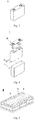
- Fig. 3 shows a sodium ion battery 5 with a square structure as an example.
- the sodium ion battery may include an outer package for packaging the positive electrode plate, the negative electrode plate, and the electrolyte.
- the outer package of the sodium ion battery may be a soft bag, such as a pocket type soft bag.
- the material of the soft bag may be plastic, for example, it may include one or more of polypropylene (PP), polybutylene terephthalate (PBT), polybutylene succinate (PBS), and the like.
- the outer package of the sodium ion battery may also be a hard case, such as a hard plastic case, an aluminum case, a steel case, and the like.
- the outer package may include a shell 51 and a cover plate 53.
- the shell 51 may include a bottom plate and side plates connected to the bottom plate, and the bottom plate and the side plates enclose a receiving cavity.
- the shell 51 has an opening communicated with the receiving cavity, and the cover plate 53 can cover the opening to close the receiving cavity.
- the positive electrode plate, the negative electrode plate, and the separator may form an electrode assembly 52 by stacking or winding.
- the electrode assembly 52 is packaged in the receiving cavity.
- the electrolyte may adopt electrolyte liquid, and the electrolyte liquid infiltrates the electrode assembly 52.
- the sodium ion battery 5 includes one or more electrode assemblies 52, which can be adjusted according to requirements.
- the sodium ion batteries may be assembled into a battery module, the battery module may include a plurality of secondary batteries, and the specific number can be adjusted according to the application and capacity of the battery module.
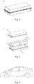
- Fig. 5 shows a battery module 4 as an example.
- the plurality of sodium ion batteries 5 may be arranged sequentially in a length direction of the battery module 4. Of course, they may also be arranged in any other way. Further, a plurality of sodium ion batteries 5 may be fixed by fasteners.
- the battery module 4 may further include a housing having a receiving space, and a plurality of sodium ion batteries 5 are received in the receiving space.
- the above-mentioned battery module may also be assembled into a battery pack, and the number of battery modules included in the battery pack can be adjusted according to the application and capacity of the battery pack.
- Figs. 6 and 7 show a battery pack 1 as an example.
- the battery pack 1 may include a battery case and a plurality of battery modules 4 disposed in the battery cabinet.
- the battery cabinet includes an upper case body 2 and a lower case body 3.
- the upper case body 2 can cover the lower case body 3 to form a closed space for receiving the battery modules 4.
- a plurality of battery modules 4 can be arranged in the battery cabinet in any manner.
- the fourth aspect of the present application provides an apparatus, the apparatus including the sodium ion battery according to the third aspect of the present application.
- the sodium ion battery can be used as a power source of the apparatus, or as an energy storage unit of the apparatus.
- the apparatus may be, but is not limited to, a mobile device (e.g., a mobile phone, a notebook computer, and the like), an electric vehicle (e.g., a pure electric vehicle, a hybrid electric vehicle, a plug-in hybrid electric vehicle, an electric bicycle, an electric scooter, an electric golf vehicle, an electric truck and the like), an electric train, a ship, a satellite, an energy storage system, and the like.
- the apparatus may select the sodium ion battery, the battery module, or the battery pack according to its usage requirements.
- Fig. 8 shows an apparatus as an example.
- the apparatus is a pure electric vehicle, a hybrid electric vehicle, or a plug-in hybrid electric vehicle.
- a battery pack or a battery module may be used.
- the apparatus may be a mobile phone, a tablet computer, a notebook computer, and the like.
- the apparatus is generally required to be thin and light, and the sodium ion battery can be used as a power source.
- reaction solution was carried out reaction for 20h at a temperature of 50°C with a stirring rate of 800rpm, the resulting coprecipitation product was isolated and collected. After that, the product was washed several times with a moderate amount of deionized water, and was dried at 100°C in a vacuum drying oven to obtain a transitional metal source [Cu 1.1 Mn 2.0 ][CO 3 ] 3.1 .
- the positive electrode active material prepared above, conductive black Super P, and PVDF as a binder at a weight ratio of 90:5:5 were mixed in an appropriate amount of N-methyl pyrrolidone (NMP) to form a uniform positive electrode slurry; the positive electrode slurry was coated on an aluminum foil as a positive electrode current collector. After drying, it was stamped into a wafer with a diameter of 14mm.
- NMP N-methyl pyrrolidone
- a metallic sodium sheet was stamped into a wafer with a diameter of 14mm.
- Fiberglass film was used as a separator.
- Ethylene carbonate (EC) and propylene carbonate (PC) were mixed in an equal volume to get an organic solvent, and sodium perchlorate NaClO 4 was dissolved in the said organic solvent to obtain the electrolyte, in which the concentration of NaClO 4 was 1mol/L.
- Examples from 2 to 19 and Comparative Examples from 1 to 3 are similar to example 1 with the exception that the reaction parameters for the preparation process of positive electrode active material were adjusted. Refer to Table 1 below for the specific parameters.
- the sodium ion batteries prepared by the examples and comparative examples were charged at a constant current to 4.3V at a rate of 2C rate and then discharged to 2.1V at a rate of 2C so as to get the specific discharge capacity of sodium ion battery at the rate of 2C. 4 samples were tested for every example and Comparative Example, with an average taken for the test result.
- the sodium ion batteries prepared by the examples and comparative examples were charged at a constant current to 4.3V at a rate of 0.1C, where the charge capacity at this time was recorded as the first-cycle charge capacity of sodium ion battery; after set standing for 5min, they were discharged at a constant current to 2.1V at a rate of 0.1C, and then set standing for 5min. This was a charging/discharging cycle. At this time, the discharge capacity was recorded as a first-cycle discharge specific capacity of the sodium-ion battery, which was the initial capacity of the sodium-ion battery.
- the sodium ion battery was subjected to the above charging/discharging cycle test for 300 cycles, and the specific discharge capacity at the 300 th cycle was detected.
- the capacity retention rate of the sodium ion battery for 300 cycle % the specific discharge capacity at the 300 th cycle/the specific discharge capacity at the first cycle ⁇ 100% .
- Example 1 Copper salt Manganese salt M salt Total concentration of metal ions mol/L Type and concentration of precipitant Type and concentration of complexing agent pH Reaction temperature and time Sintering temperature and time
- Example 1 Copper sulfate Manganese sulfate / 1.2 4mol/L 2mol/L 11.0 50°C 800°C Sodium carbonate Ammonia 20h 16h
- Example 2 Copper sulfate Manganese sulfate / 1.2 4mol/L 2mol/L 11.0 50°C 800°C Sodium carbonate Ammonia 20h 12h
- Example 3 Copper sulfate Manganese sulfate / 1.2 4mol/L 2mol/L 11.0 50°C 800°C Sodium carbonate Ammonia 20h 8h
- Example 4 Copper nitrate Manganese nitrate / 1.8 6mol/L 1mol/L 11.4 55°C 760°C Sodium carbonate Ammonia 20h 16h
- Example 3 Copper nitrate Manganese n
- the sodium content of the positive electrode active material was relatively high, the stability of the material to air, water, and CO 2 was relatively poor, the first-cycle specific discharge capacity was relatively low, the rate performance was relatively poor, and the capacity retention ratio during charging/discharging cycles was relatively low.
- the present application significantly improved the first-cycle specific discharge capacity, the electric performance at a large current, and the capacity retention ratio during charging/discharging cycles of the positive electrode active material by making the positive electrode active material with the specific chemical composition as described above so that the positive electrode active material may have both relatively high capacity elaboration and relatively high rate performance and cycle performance.
Landscapes
- Chemical & Material Sciences (AREA)
- Chemical Kinetics & Catalysis (AREA)
- Electrochemistry (AREA)
- General Chemical & Material Sciences (AREA)
- Inorganic Chemistry (AREA)
- Engineering & Computer Science (AREA)
- Organic Chemistry (AREA)
- Materials Engineering (AREA)
- Manufacturing & Machinery (AREA)
- Battery Electrode And Active Subsutance (AREA)
- Secondary Cells (AREA)
Abstract
Description
- This application claims priority of
Chinese patent application No. 201910026561.1 entitled "positive electrode active material, positive electrode plate, and sodium ion battery" and filed on January 11, 2019 - This application belongs to the technical field of energy storage apparatuses, and specifically involves a positive electrode active material and its preparation method, a sodium ion battery, and an apparatus containing the sodium ion battery.
- At present, a lithium-ion battery dominates the power battery. Nevertheless, the lithium-ion battery is facing a great challenge, such as the increasing shortage of lithium resources, the continuous increase of upstream material price, the sluggish development of recycling technology, and a low recycling rate of old and used batteries. Sodium ion batteries can realize charging and discharging by an intercalation-deintercalation process between positive and negative electrodes. Moreover, compared with lithium, sodium has the advantages of much richer reserves, wider distribution, and lower cost. Therefore, the sodium ion battery is likely to become a new generation of electrochemical system to replace the lithium-ion battery. However, cycle performance of a sodium ion battery under extensive research at present is relatively poor, which hinders the commercialization progress of sodium ion battery.
- In a first aspect, this application provides a positive electrode active material that satisfies the chemical formula of Na2+x Cu h Mn k M l O7-y , where M is one or more selected from Li, B, Mg, Al, K, Ca, Ti, V, Cr, Fe, Co, Ni, Zn, Ga, Sr, Y, Nb, Mo, Sn, Ba, and W, 0≤x≤0.5, 0.1<h≤2, 1≤k≤3, 0≤l≤0.5, and 0≤y≤1; wherein, 2≤h+k+l≤3.5, and 0.57≤(2+x) / (h+k+l)≤0.9.
- In a second aspect, this application provides a method for preparing a positive electrode active material, including the following steps:
- providing a mixed solution, wherein the mixed solution comprises copper salts and manganese salts, and the salts containing an Mn element is present in the mixed solution in an amount of 0 or more;
- adding a precipitant and a complexing agent into the mixed solution, and then subjecting it to coprecipitation to obtain a precursor; and
- mixing the precursor and a sodium source to obtain a mixture and sintering the mixture to obtain the positive electrode active material,
- wherein the positive electrode active material satisfies a chemical formula Na2+x Cu h Mn k M l O7-y , where M is one or more selected from of Li, B, Mg, Al, K, Ca, Ti, V, Cr, Fe, Co, Ni, Zn, Ga, Sr, Y, Nb, Mo, Sn, Ba and W; 0≤x≤0.5, 0.1<h≤2, 1≤k≤3, 0≤l≤0.5, 0≤y≤1, 2≤h+k+l≤3.5, and 0.57≤(2+x)/(h+k+l)≤0.9.
- In a third aspect, this application provides a sodium ion battery comprising a positive electrode plate containing the positive electrode active material in the first aspect of this application.
- In the fourth aspect, this application provides an apparatus comprising the sodium ion battery in the third aspect of this application.
- Compared with the existing technologies, this application at least has the following beneficial effects.
- The positive electrode active material provided in this application satisfies the chemical formula of Na2+x Cu h Mn k M l O7-y , with a specific chemical composition, which enable the positive electrode active material to have relatively high ionic and electronic conductivity, and relative high structural stability so that the positive electrode active material is of relatively high cycle performance. The sodium ion battery adopting this positive electrode active material achieves a relatively high cycle performance as a result. More preferably, the positive electrode active material also has a relatively high rate capability, which can improve the rate performance of sodium ion battery in turn.
- Particularly preferably, the positive electrode active material also has two relatively high charge/discharge voltage plateaus, which are relatively long and flat. Moreover, the capacity of these voltage plateaus accounts for a higher ratio of the full charge capacity of the corresponding cycle. Thus, the charging/discharge capacity elaboration and material utilization rate of the positive electrode active material are improved. Therefore, the sodium ion battery adopting this positive electrode active material achieves a relatively high energy density.
- The apparatus of this application includes the sodium ion battery provides in this application so that it at least has the same advantages as the said sodium ion battery.
- In order to explain the technical solutions of the embodiments of the present application more clearly, the following will briefly introduce the drawings that need to be used in the embodiments of the present application. Obviously, the drawings described below are only some embodiments of the present application. A person of ordinary skill in the art can obtain other drawings based on the drawings without creative work.
-
Fig. 1 is a first-cycle charging/discharging curve graph of the sodium ion battery provided in Example 6 of this application. -
Fig. 2 is a first-cycle charging/discharging curve graph of the sodium ion battery provided in Example 11 of this application. -
Fig. 3 is a schematic diagram of an embodiment of a sodium ion battery. -
Fig. 4 is an exploded view ofFig. 3 . -
Fig. 5 is a schematic diagram of an embodiment of battery module. -
Fig. 6 is a schematic diagram of an embodiment of battery pack. -
Fig. 7 is an exploded view ofFig. 6 . -
Fig. 8 is a schematic diagram of an embodiment of an apparatus using the sodium ion battery as a power source. - In order to make the objectives, technical solutions and beneficial technical effects of the present application clearer, the present application will be further described in detail below in conjunction with embodiments. It should be understood that the embodiments described in this specification are only for explaining the application, not intending to limit the application.
- For the sake of brevity, only certain numerical ranges are explicitly disclosed herein. However, any lower limit may be combined with any upper limit to form a range that is not explicitly described; and any lower limit may be combined with other lower limits to form an unspecified range, and any upper limit may be combined with any other upper limit to form an unspecified range. Further, although not explicitly specified, each point or single value between the endpoints of the range is included in the range. Thus, each point or single value can be combined with any other point or single value as its own lower limit or upper limit or combined with other lower limit or upper limit to form a range that is not explicitly specified.
- In the description herein, it should be noted that, unless otherwise specified, a numeric range described with the term "above" or "below" includes the lower or upper limit itself, and "more" in "one or more" means two or more.
- The above summary of the present application is not intended to describe each disclosed embodiment or every implementation in this application. The following description illustrates exemplary embodiments more specifically. In many places throughout the application, guidance is provided through a series of examples, which can be used in various combinations. In each instance, the enumeration is only a representative group and should not be interpreted as exhaustive.
- Firstly, the positive electrode active material in the first aspect of this application is described. This positive electrode active material satisfies the chemical formula of Na2+x Cu h Mn k M l O7-y , where M is a doping element at the transitional metal site and is one or more selected from Li, B, Mg, Al, K, Ca, Ti, V, Cr, Fe, Co, Ni, Zn, Ga, Sr, Y, Nb, Mo, Sn, Ba, and W, 0≤ x <0.5, 0.1< h ≤2, 1≤ k ≤3, 0≤ l ≤0.5, and 0≤ y ≤1; wherein, 2≤ h+k+l ≤3.5, and 0.57 ≤ (2+x)/(h+k+l) ≤ 0.9.
- The number of sodium atoms in the chemical formula of the positive electrode active material is 2 or more, which is conducive to improving the first-cycle charging/discharge capacity of the positive electrode active material. The number of sodium atoms in the chemical formula is preferred to be less than 2.5, which is conducive to improving the stability of the positive electrode active material to air, water, and CO2, and reducing the capacity loss of the positive electrode active material during the charging/discharging cycle and storage, so that the positive electrode active materials have a relatively high capacity retention ratio.
- The positive electrode active material satisfies 2≤h+k+l≤3.5, and 0.57≤(2+x)/(h+k+l)≤0.9, which can allow the positive electrode active material to have fewer defects of chemical composition, reduce impurity phases in the material, and improve internal structure and structural stability of the positive electrode active material. Particularly, this positive electrode active material also has a relatively high migration rate of sodium ion and electron, which enables the positive electrode active material to have relatively high ionic and electronic conductivity. Therefore, this positive electrode active material has relatively high capacity elaboration and relatively high cycle performance and rate performance. The sodium ion battery adopting this positive electrode active material achieves a relatively high energy density, cycle performance, and rate performance. Besides, polarization phenomenon of this battery is also reduced, and its cycle life may be further improved.
- In some embodiments, (2+x)/(h+k+l) can be ≥0.57, ≥0.60, ≥0.62, ≥0.64, ≥0.66, ≥0.68, ≥0.70, ≥0.72, ≥0.74, or ≥0.75. Further, (2+x)/(h+k+l) can be ≤0.90, ≤0.85, ≤0.80, <0.78, <0.77, <0.76, <0.75, <0.74, <0.73, <0.72, or ≤0.71. Preferably, 0.6≤(2+x)/(h+k+l)≤0.8. The positive electrode active material satisfying (2+x)/(h+k+l) within an proper range can have a better comprehensive electrochemical performance, and its capacity, cycle performance, and rate performance can be further improved.
- The positive electrode active material satisfies 0.1<h≤2 and 1≤k≤3. In the charging/discharging process of this positive electrode active material, the transfer of electrons of Cu and Mn provides an effective charge compensation for the de-intercalation and intercalation of sodium ions, thereby improving the charge/discharge voltage plateau of the positive electrode active material and enabling the positive electrode active material to have a relatively high specific capacity.
- In some embodiments, the positive electrode active material can satisfy 0.5<h≤1.5 and 1.5≤k≤2.5, which allows the positive electrode active material to have a relatively gram volume and a relatively high capacity retention ratio during the charging/discharging cycle.
- In some embodiments, the positive electrode active material can satisfy 0.9≤h≤1.5 and 1.5≤k≤2.5. Preferably, 0.9≤h≤1.2 and 1.5≤k≤2.5. As shown in
Fig. 1 , this positive electrode active material has a first discharge voltage plateau from 3.8V to 4.1V and a second discharge voltage plateau from 3.4V to 3.7V, and the charge/discharge voltage plateaus are relatively wide and flat. Therefore, the positive electrode active material satisfying h and k within a proper range improves the ratio of the capacity of voltage plateau thereof to the full charge capacity of the corresponding cycle, and behaves with a relatively high charging/discharging stability, so that the positive electrode active material has a relatively high charging/discharge capacity elaboration and material utilization rate. Besides, the positive electrode active material can also have relatively high cycle stability. - More preferably, this positive electrode active material has a discharge capacity Q1 at the first discharge voltage plateau, a discharge capacity Q2 at the second discharge voltage plateau, and a full discharge capacity Q that satisfy the relationship of 30%≤(Q1+Q2)/Q×100%≤90%, preferably, 50%≤(Q1+Q2)/Q×100%≤80%.
- More preferable, the discharge capacity Q1 of this positive electrode active material at the first discharge voltage plateau is from 30mAh/g to 55mAh/g, and the discharge capacity Q2 at the second discharge voltage plateau is from 30mAh/g to 75mAh/g. This positive electrode active material behaves with a relatively high voltage plateau discharge capacity.
- The full discharge capacity of the above mentioned positive electrode active material refers to a discharge capacity at which a sodium ion battery charged to a charge cut-off voltage is discharged to a discharge cut-off voltage.
- The discharge voltage plateau and discharge capacity of the positive electrode active material are measured by charging a battery to a charge cut-off voltage at the constant current of 0.1C and discharging it to a discharge cut-off voltage at 0.1C. The tested battery is composed of a positive electrode plate comprising a positive electrode active material, a conductive carbon black, and a binder polyvinylidene fluoride at a weight ratio of 90:5:5, and a sodium metal plate as a negative electrode.
- In some embodiments, the positive electrode active material can satisfy k/(h+l)≥1.4, which can further improve the capacity elaboration and kinetic performance of the positive electrode active material and endow the positive electrode active material with a higher first-cycle specific discharge capacity and rate performance. Preferably, 1.6≤k/(h+l)≤6.
- In some embodiments, the positive electrode active material can satisfy 0<l≤0.5. By doping M element at the transitional metal site, specific capacity and rate performance of the positive electrode active material can be further improved.
- Preferably, M can be one or more selected from Li, Zn, B, Mg, Al, Ti, Fe, Co, Ni, and W. More preferably, M can be one or more selected from Li, Zn, Ti, Fe, Ni, and W. Particularly preferably, M can be one or more selected from Zn, B, Ti, and W.
- In some embodiments, the specific surface area of the positive electrode active material is preferable to be from 0.01m2/g to 20m2/g, more preferable to be from 0.1m2/g to 15m2/g, and particularly preferable to be from 0.1m2/g to 5m2/g. When the specific surface area of the positive electrode active material is more than 0.01m2/g, it can ensure that the positive electrode active material has a relatively small particle size, and that the transmission path between sodium ions and electrons is relatively short, which can improve the ionic and electronic conductivity of the positive electrode active material, thereby improving the electrochemical kinetics performance and rate performance during its charging/discharging process. Meanwhile, the sodium ion battery adopting this positive electrode active material has a relatively small positive polarization phenomenon, thereby improving the capacity retention ratio in the charging/discharging cycle process. The positive electrode active material having a specific surface area of less than 20m2/g ensure that the particle size of the positive electrode active material is not excessively small, so that the positive electrode active material can both have relatively high electrochemical performance and the agglomeration between the particles of the positive electrode active material may be effectively inhibited, thereby enabling the positive electrode to have relatively high rate performance and cycle performance.
- The positive electrode active material having a specific surface area within a proper range can reduce imbibition phenomenon during the preparation of positive electrode slurry and improve solid content and particle dispersion uniformity of the positive electrode slurry, thereby improving the particle dispersion uniformity and compaction density of the positive electrode active material layer, the energy density of batteries, and the rate performance and cycle performance of batteries.
- In some embodiments, the average particle size Dv50 of the positive electrode active material is preferable to be from 0.5µm to 25µm, more preferable to be from 1µm to 15µm, and particularly preferable to be from 8µm to 15µm.
- In some embodiments, the tap density of the positive electrode active material is preferable to be from 0.5g/cm3 to 3.5g/cm3, more preferable, from 1.5g/cm3 to 3.0g/cm3.
- In some embodiments, the compaction density of the positive electrode active material at a pressure of 8 tons is preferable to be from 2.5g/cm3 to 4.5g/cm3, more preferable, from 3.5g/cm3 to 4.5g/cm3. The positive electrode plate adopting this positive electrode active material can have a relatively high compaction density, thereby improving the energy density of batteries.
- In some embodiments, the powder resistivity of the positive electrode active material at a pressure of 12MPa is preferable to be from 10Ω·cm to 300kΩ·cm, more preferable, from 20Ω·cm to 3kΩ·cm. The positive electrode active material having a powder resistivity within a proper range can further improve the rate performance of sodium ion battery and endow the sodium ion battery with relatively high safety performance.
- In some embodiments, the shape of the positive electrode active material is preferable to be one or more of sphere, globoid, and polygon flake. Spherical and globoid positive electrode active materials can be secondary particles composed of primary particle by aggregation, and the shape of primary particle can be sphere, globoid, or flake. The positive electrode active material with a polygon-flake structure can be one or more of triangular flake, tetragonal flake, and hexagonal flake. The positive electrode active material with a proper shape can have a more stable structure during the charging/discharging cycle so that the sodium ion battery can have a better cycle performance.
- In some embodiments, the positive electrode active material has a triclinic phase crystal structure or a hexagonal phase crystal structure. This positive electrode active material has a better structural stability, and its structural change caused by the process of de-intercalation and intercalation of sodium ions is relatively small, constituting a good main framework for the reversible de-intercalation and intercalation of sodium ions. Therefore the positive electrode active material may have improved capacity elaboration and cycle performance.
- Furthermore, when the positive electrode active material is of the triclinic phase structure, its X-ray diffraction specturm comprises a first diffraction peak at an X-ray diffraction angle 2θ of from 15.8° to 16.0° generated by (110) crystal plane and a second diffraction peak at an X-ray diffraction angle 2θ of from 32.0° to 32.2° generated by (202) crystal plane, and an intensity ratio of the first diffraction peak to the second diffraction peak is from 5 to 30, the first diffraction peak has a full width at half maxima (FWHM) of from 0.02° to 0.5°, and the second diffraction peak has a full width at half maxima (FWHM) of from 0.02° to 0.5°.
- Furthermore, when the positive electrode active material is of the hexagonal phase structure, its X-ray diffraction specturm comprises a first diffraction peak at an X-ray diffraction angle 2θ of from 15.8° to 16.0° generated by (002) crystal plane and a second diffraction peak at an X-ray diffraction angle 2θ of from 32.0° to 32.2° generated by (004) crystal plane, and an intensity ratio of the first diffraction peak to the second diffraction peak is from 5 to 30; the first diffraction peak has a full width at half maxima of from 0.02° to 0.5°, and the second diffraction peak has a full width at half maxima of from 0.02° to 0.5°.
- The positive electrode active material having the said crystal structure has a relatively good crystallinity degree, which is conducive to further improving the capacity elaboration and cycle performance of positive electrode active material.
- The crystal structure of positive electrode active material can be measured by an X-ray powder diffractometer. For example, with Brucker D8A_A25 X-ray diffractometer of Brucker AxS, CuKα ray is regarded as a radiation source, the ray wavelength λ=1.5418Å, the scanning 2θ angle range is from 10° to 90°, and the scanning rate is 4°/min.
- The specific surface area of positive electrode active material is of the meaning known in this field and can be measured by the known instruments and methods in this field. For example, it can be tested by the analysis test method of nitrogen adsorption specific surface area and calculated by BET (Brunauer Emmett Teller) method in which the analysis test method of nitrogen absorption specific surface area can be carried out by the Tri StarII specific surface and pore analyzer from Micromeritics, USA.
- The average particle size of positive electrode active material Dv50 is of the meaning known in this field and can be measured by the instruments and methods known in this field. For example, it can be conveniently measured by a laser particle size analyzer, such as the Mastersizer 3000 laser particle size analyzer of Malvern Instrument, UK.
- The shape of positive electrode active material can be measured by the instruments and methods known in this field. For example, it can be detected by a field emission scanning electron microscope, such as SIGMA 500 high-resolution field emission scanning electron microscope of Karl Zeiss AG, Germany.
- The tap density of positive electrode active material can be measured by the instruments and methods known in this field. For example, it can be measured conveniently by a tap density tester, such as the FZS4-4B tap density tester.
- The compaction density of positive electrode active material can be measured by the instruments and methods known in this field. For example, it can be measured conveniently by an electron pressure tester, such as the UTM7305 electron pressure tester.
- In the following, the preparation method of the positive electrode active material provided in the second aspect of this application will be introduced. According to this preparation method, the said positive electrode active material can be prepared. The preparation method of the positive electrode active material includes the following steps:
- S10. adding a copper salt, a manganese salt, and an optional salt containing M element to a solvent in a stoichiometric ratio to prepare a mixed solution;
- S20. adding a precipitant and a complexing agent to the mixed solution to prepare a reaction solution, and adjusting a pH value of the reaction solution to a preset range;
- S30. subjecting the reaction solution to coprecipitation reaction at a preset temperature and stirring speed, separating and collecting the resulting coprecipitation products, washing the precipitation products several times with a moderate amount of solvent, and drying them at a preset temperature to get a transitional metal source [Cu h Mn k M l ]X u , wherein X is a negative ion taken from the precipitant, and h, k, l, and u allow the chemical formula [Cu h Mn k M l ]X u to be electrically neutral; and
- S40. mixing the transitional metal source and sodium source to obtain a mixture and sintering the mixture, and washing and drying the resulting sintering product to obtain the positive electrode active material.
- As different reactants have different dissociation intensities in a solvent and a same reactant has different dissociation intensities in different solvents, the response rate is affected, including crystal nucleation and growth rate, so the chemical composition, specific surface area, particle size, shape, and crystal structure of the transitional metal source are affected, and finally the chemical composition, specific surface area, particle size, shape, and crystal structure of the positive electrode active material are affected. In addition, the oxidation valence state of metal atoms in reactants also affects the electrochemical performance of the final product-positive electrode active material.
- In some preferred embodiments, in the step S10, the copper salt may include one or more of copper nitrate, copper chloride, copper sulfate, copper oxalate, and copper acetate, preferably, one or more of copper nitrate and copper sulfate. The manganese salt may include one or more of manganese nitrate, manganese chloride, manganese sulfate, manganese oxalate, and manganese acetate, preferably, one or more of manganese nitrate and manganese sulfate. The salt containing M element can be one or more of nitrates, chlorates, sulfates, oxalates, and acetates containing M element, preferably, one or more of nitrates and sulfates containing M element. For example, when M is Fe, the salt containing M element can include one or more of ferrous nitrate, ferric nitrate, ferrous chloride, ferric chloride, ferrous sulfate, ferric sulfate, ferrous oxalate, ferric oxalate, ferrous acetate, and ferric acetate, preferably, one or more of ferrous nitrate, ferric nitrate, ferrous sulfate, and ferric sulfate. For example, when M is Zn, the salt containing M element can include one or more of zinc nitrate, zinc chloride, zinc sulfate, zinc oxalate, and zinc acetate, preferably, one or more of zinc nitrate and zinc sulfate. The solvent can include one or more of deionized water, methanol, ethanol, acetone, isopropyl alcohol, and n-hexyl alcohol, preferably, deionized water.
- Reactants having different concentrations in the reaction solution, on the one hand, enables the reactants to have different dissociation rates, thereby affecting the reaction rate, on the other hand, directly affects the reaction rate, thereby affecting the chemical composition and structure of the transitional metal source, and finally affecting the chemical composition and structure of the positive electrode active material.
- In some preferred embodiments, in the step S10, the total concentration of metal ions in the mixed solution is preferable to be from 0.1mol/L to 10mol/L, more preferable, from 0.5mol/L to 5mol/L.
- In the reaction system, the type and concentration of precipitant affect its reaction rate with metal ions, and the type and concentration of complexing agent significantly affect the crystal nucleation and growth of the transitional metal source, which both affect the chemical composition and structure of the transitional metal source.
- In some preferred embodiments, in the step S20, the precipitant can include one or more of sodium hydroxide, potassium hydroxide, sodium bicarbonate, sodium carbonate, potassium bicarbonate, and potassium carbonate, preferably, one or more of sodium carbonate and sodium hydroxide. The complexing agent can include one or more of ammonia, ammonium carbonate, urea, hexamethylene tetramine, ethylenediamine tetraacetic acid, citric acid and ascorbic acid, preferably, ammonia.
- The pH value of the reaction system affects the precipitation rate of every metal ion, thereby directly affecting the crystal nucleation and growth rate of the transitional metal source, further affecting the chemical composition and structure of the transitional metal source, and finally affecting the chemical composition and structure of the positive electrode active material. In order to achieve the positive electrode active material in this application, in the step S20, preferably, the pH value of the reaction solution is controlled to be from 6 to 13. More preferably, the pH value of the reaction solution is controlled to be from 10 to 12. When necessary, the pH value of the reaction solution can be adjusted by adjusting the type and content of precipitant and/or complexing agent.
- In some examples, the step S20 can include:
- S21. providing a solution of precipitant and a solution of complexing agent;
- S22. Adding the solution of precipitant and the solution of complexing agent to the mixed solution to obtain a reaction solution, and adjusting a pH value of the reaction solution to a preset range.
- In some examples, the step S21 comprises dispersing a precipitant into a solvent to obtain a solution of precipitant.
- The solvent used for the solution of precipitant can be one or more of deionized water, methyl alcohol, ethyl alcohol, acetone, isopropyl alcohol, and n-hexyl alcohol.
- In some examples, the concentration of precipitant in the solution of precipitant is preferable to be from 0.5mol/L to 15mol/L, more preferable, from 2mol/L to 10mol/L.
- In some examples, the step S21 comprising dispersing a complexing agent into a solvent to obtain a solution of complexing agent.
- The solvent used for the solution of complexing agent can be one or more of deionized water, methyl alcohol, ethyl alcohol, acetone, isopropyl alcohol, and n-hexyl alcohol.
- In some examples, the concentration of complexing agent in the solution of complexing agent is preferable to be from 0.1mol/L to 15mol/L, more preferable, from 0.5mol/L to 10mol/L.
- In addition, the temperature of the reaction system directly affects the chemical reaction rate and the reaction yield and the reaction time affects the growth process of reaction products, thereby affecting the chemical composition and structure of the reaction products. In some embodiments, preferably, in the step S30, the reaction temperature is from 25°C to 70°C, more preferable, from 40°C to 65°C, and particularly preferable, from 50°C to 60°C. The reaction time is preferable to be from 10h to 60h, more preferable, from 15h to 30h.
- The stirring rate during the reaction affects the mixing uniformity of materials so that it has an important influence on the effect of complexation and precipitation, and further affects the structure of the transitional metal source. In some embodiments, preferably, in the step S30, the stirring rate is from 200rpm to 1600rpm, for example, from 300rpm to 1000rpm, or from 500rpm to 900rpm. The abbreviation "rpm", refers to round per minute, which characterizes the number of revolution of the stirring equipment per minute.
- In some embodiments, the drying temperature in the step S30 is preferable to be from 80°C to 120°C. The drying time in the step S30 is preferable to be from 2h to 48h.
- In the step S40, the temperature and time of sintering affect the specific surface area, particle size, shape, and crystal structure of the reaction products. In some embodiments, preferably, in the step S40, the temperature of sintering is from 500°C to 900°C, more preferably, from 550°C to 850°C. The time of sintering is preferable to be from 4h to 30h, more preferable, from 8h to 20h.
- In some embodiments, in the step S40, the sodium source can be one or more of sodium carbonate, sodium hydroxide, and sodium nitrate.
- In the step S40, the sintering can be carried out in an air or oxygen atmosphere.
- In the steps S30 and S40, the detergent used for washing and the number of washing are not specially restricted and can be selected according to the actual demand as long as the residual ions on the surface of products are removed. For example, deionized water can be used as a detergent.
- During the preparation process of positive electrode active material, by comprehensively controlling the type and content of reactants, pH value, the type and concentration of precipitant, the type and concentration of complexing agent, reaction temperature, stirring rate, reaction time, and sintering temperature and time enables the positive electrode active material to have a specific chemical composition and structure stated in this application, which can greatly improve the electrochemical performance of the positive electrode active material and finally improve the specific capacity, rate performance, and cycle performance of the sodium ion battery.
- This application also provides a positive electrode plate comprising a positive electrode current collector and a positive electrode active material layer disposed on the positive electrode current collector. For example, the positive electrode current collector has two opposite surfaces and the positive electrode active material layer is laminated on either or both of the two surfaces of the positive electrode current collector.
- A metal foil, a carbon-coated metal foil, or a porous metal sheet can be adopted for the positive electrode current collector, preferably, an aluminum foil.
- The positive electrode active material layer includes the positive electrode active material in the first aspect of this application. Optionally, the positive electrode active material in the positive electrode active material layer is one or more of Na2.2Cu1.1Mn2.0O7, Na2.0Cu0.9Mn2.0O7, Na2.0Cu0.6Mn2.4O7, Na2.0Cu0.4Mn2.4Fe0.2O7, and Na2.0Cu0.4Mn2.4Zn0.2O7.
- In some examples, the positive electrode active material layer can also include a binder. The binder can include one or more of styrene-butadiene rubber (SBR), water-based acrylic resin, sodium carboxymethyl cellulose (CMC-Na), polyvinylidene fluoride (PVDF), polytetrafluoroethylene (PTFE), ethylene-vinyl acetate copolymer (EVA) and polyvinyl alcohol (PVA).
- In some examples, the positive electrode active material layer can also include a conductive agent. The conductive agent can include one or more of super-conductive carbon, acetylene black, carbon black, ketjen black, carbon dot, carbon nanotubes, graphene, and carbon nanofiber.
- The positive electrode plate can be prepared according to the conventional method in this field. Usually, the positive electrode plate is obtained by dispersing the positive electrode active material and optional conductive agent and binder in a solvent (e.g., N-methyl-2-pyrrolidone. NMP for short) to form an uniform positive electrode slurry, coating a positive electrode current collector with the positive electrode slurry and then carrying out the processes of drying and cold pressing.
- As the positive electrode plate of this application adopts the positive electrode active material in the first aspect of this application, it has a relatively high comprehensive electrochemical performance.
- In a third aspect, this application provides a sodium ion battery including the said positive electrode plate containing one or more positive electrode active materials of this application.
- Sodium ion battery also includes a negative electrode plate, a separator, and an electrolyte.
- In some embodiments, the negative electrode plate can be a metallic sodium sheet.
- In some embodiments, the negative electrode plate can include a negative electrode current collector and a negative electrode active material layer disposed on the negative electrode current collector. For example, the negative electrode current collector has two opposite surfaces and the negative electrode active material layer is laminated on either or both of the two surfaces of the negative electrode current collector.
- In some embodiments, a metal foil, a carbon-coated metal foil, a porous metal sheet, and other materials can be adopted for the negative electrode current collector, preferably, a copper foil.
- The negative electrode active material layer includes a negative electrode active material, which can be the known negative electrode active material in this field. As an example, the negative electrode active material can include, but is not limited to, one or more of natural graphite, artificial graphite, mesocarbon microbeads (MCMB), hard carbon, and soft carbon.
- In some embodiments, the negative electrode active material layer can also include a conductive agent, which can be the known conductive agent used for battery negative electrode in this field. As an example, the conductive agent can include, but is not limited to, one or more of super-conductive carbon, acetylene black, carbon black, ketjen black, carbon dot, carbon nanotubes, graphene, and carbon nanofiber.
- In some embodiments, the negative electrode active material layer can also include a binder, which can be the known binder used for battery negative electrode in this field. As an example, the binder can include, but is not limited to, one or more of styrene-butadiene rubber (SBR), water-based acrylic resin, and sodium carboxymethyl cellulose (CMC-Na).
- In some examples, the negative electrode active material layer can also include a thickening agent, which can be the known thickening agent used for battery negative electrode in this field. As an example, the thickening agent can include, but not limited to, sodium carboxymethyl cellulose (CMC-Na).
- The said negative electrode plate can be prepared according to the conventional method in this field. Usually, the negative electrode plate is obtained by dispersing the negative electrode active material and optional conductive agent, binder and thickener in a solvent in which the solvent may be deionized water to form an uniform negative electrode slurry, coating a negative electrode current collector with the negative electrode slurry and then carrying out the processes of drying and cold pressing.
- There is no special restriction on the separator. Any known porous separator with chemical stability and mechanical stability can be selected, for example, glass fiber, non-woven fabrics, polyethylene, polypropylene, polyvinylidene dichloride, and their multi-layer composite film.
- In some embodiments, the electrolyte can include an organic solvent and an electrolyte sodium salt. As an example, the organic solvent can include one or more of ethylene carbonate (EC), propylene carbonate (PC), ethyl methyl carbonate (EMC) and diethyl carbonate (DEC). The electrolyte sodium salt can include one or more of NaPF6, NaClO4, NaBCl4, NaSO3CF3, and Na(CH3)C6H4SO3.
- As the sodium ion battery of this application adopts the positive electrode active material in the first aspect of this application, it has a relatively high comprehensive electrochemical performance, including relatively high first-cycle specific discharge capacity and energy density, as well as relatively high rate performance and cycle performance. By adopting the positive electrode active material of this application, the electrochemical window of sodium ion battery is also enlarged to allow the sodium ion battery to charge and discharge within a relatively wide electrochemical window without affecting the specific capacity and energy density of the battery.
- The present application does not have particular limitation to the shape of the sodium ion battery. The sodium ion battery may be cylindrical, square, or in other arbitrary shape.
Fig. 3 shows asodium ion battery 5 with a square structure as an example. - In some embodiments, the sodium ion battery may include an outer package for packaging the positive electrode plate, the negative electrode plate, and the electrolyte.
- In some embodiments, the outer package of the sodium ion battery may be a soft bag, such as a pocket type soft bag. The material of the soft bag may be plastic, for example, it may include one or more of polypropylene (PP), polybutylene terephthalate (PBT), polybutylene succinate (PBS), and the like. The outer package of the sodium ion battery may also be a hard case, such as a hard plastic case, an aluminum case, a steel case, and the like.
- In some embodiments, referring to
Fig. 4 , the outer package may include ashell 51 and acover plate 53. Theshell 51 may include a bottom plate and side plates connected to the bottom plate, and the bottom plate and the side plates enclose a receiving cavity. Theshell 51 has an opening communicated with the receiving cavity, and thecover plate 53 can cover the opening to close the receiving cavity. - The positive electrode plate, the negative electrode plate, and the separator may form an
electrode assembly 52 by stacking or winding. Theelectrode assembly 52 is packaged in the receiving cavity. The electrolyte may adopt electrolyte liquid, and the electrolyte liquid infiltrates theelectrode assembly 52. - The
sodium ion battery 5 includes one ormore electrode assemblies 52, which can be adjusted according to requirements. - In some embodiments, the sodium ion batteries may be assembled into a battery module, the battery module may include a plurality of secondary batteries, and the specific number can be adjusted according to the application and capacity of the battery module.
-
Fig. 5 shows a battery module 4 as an example. Referring toFig. 5 , in the battery module 4, the plurality ofsodium ion batteries 5 may be arranged sequentially in a length direction of the battery module 4. Of course, they may also be arranged in any other way. Further, a plurality ofsodium ion batteries 5 may be fixed by fasteners. - Optionally, the battery module 4 may further include a housing having a receiving space, and a plurality of
sodium ion batteries 5 are received in the receiving space. - In some embodiments, the above-mentioned battery module may also be assembled into a battery pack, and the number of battery modules included in the battery pack can be adjusted according to the application and capacity of the battery pack.
-
Figs. 6 and 7 show abattery pack 1 as an example. Referring toFigs. 6 and 7 , thebattery pack 1 may include a battery case and a plurality of battery modules 4 disposed in the battery cabinet. The battery cabinet includes an upper case body 2 and a lower case body 3. The upper case body 2 can cover the lower case body 3 to form a closed space for receiving the battery modules 4. A plurality of battery modules 4 can be arranged in the battery cabinet in any manner. - The fourth aspect of the present application provides an apparatus, the apparatus including the sodium ion battery according to the third aspect of the present application. The sodium ion battery can be used as a power source of the apparatus, or as an energy storage unit of the apparatus. The apparatus may be, but is not limited to, a mobile device (e.g., a mobile phone, a notebook computer, and the like), an electric vehicle (e.g., a pure electric vehicle, a hybrid electric vehicle, a plug-in hybrid electric vehicle, an electric bicycle, an electric scooter, an electric golf vehicle, an electric truck and the like), an electric train, a ship, a satellite, an energy storage system, and the like.
- The apparatus may select the sodium ion battery, the battery module, or the battery pack according to its usage requirements.
-
Fig. 8 shows an apparatus as an example. The apparatus is a pure electric vehicle, a hybrid electric vehicle, or a plug-in hybrid electric vehicle. In order to meet the requirements of the apparatus for high power and high energy density of the sodium ion battery, a battery pack or a battery module may be used. - As another example, the apparatus may be a mobile phone, a tablet computer, a notebook computer, and the like. The apparatus is generally required to be thin and light, and the sodium ion battery can be used as a power source.
- The following examples more specifically describe the content disclosed in the present application, and these examples are only used for explanatory description, because various modifications and changes within the scope of the present disclosure are obvious to those skilled in the art. Unless otherwise stated, all parts, percentages, and ratios described in the following examples are based on weight, all reagents used in the examples are commercially available or synthesized according to conventional methods and can be directly used without further treatment, and all instruments used in the examples are commercially available.
- S10. Copper sulfate pentahydrate and manganese sulfate monohydrate were dissolved in a deionized water in a stoichiometric ratio under the protection of inert atmosphere to prepare a mixed solution, in which the total concentration of metal ions was 1.2mol/L.
- S21. Sodium carbonate as a precipitant was dispersed in a deionized water to prepare a solution of precipitant, in which the concentration of sodium carbonate was 4mol/L. An ammonia with a concentration of 2mol/L was used as a solution of complexing agent.
- S22. The solution of precipitant and the solution of complexing agent were added to the above mixed solution to obtain a reaction solution, and the pH value of the reaction solution was controlled to 11.0.
- S30. The reaction solution was carried out reaction for 20h at a temperature of 50°C with a stirring rate of 800rpm, the resulting coprecipitation product was isolated and collected. After that, the product was washed several times with a moderate amount of deionized water, and was dried at 100°C in a vacuum drying oven to obtain a transitional metal source [Cu1.1Mn2.0][CO3]3.1.
- S40. Sodium hydroxide and the transitional metal source were mixed uniformly in a stoichiometric ratio to obtain a mixture, and the mixture was sintered at a temperature of 800°C under an air atmosphere for 16h. After that, the sintered product was cooled to room temperature, and then washed several times with a moderate amount of deionized water followed by drying to obtain the positive electrode active material.
- The positive electrode active material prepared above, conductive black Super P, and PVDF as a binder at a weight ratio of 90:5:5 were mixed in an appropriate amount of N-methyl pyrrolidone (NMP) to form a uniform positive electrode slurry; the positive electrode slurry was coated on an aluminum foil as a positive electrode current collector. After drying, it was stamped into a wafer with a diameter of 14mm.
- A metallic sodium sheet was stamped into a wafer with a diameter of 14mm.
- Ethylene carbonate (EC) and propylene carbonate (PC) were mixed in an equal volume to get an organic solvent, and sodium perchlorate NaClO4 was dissolved in the said organic solvent to obtain the electrolyte, in which the concentration of NaClO4 was 1mol/L.
- 5) The said positive electrode plate, separator, and negative electrode plate were stacked in order in which the said electrolyte was added and which was sealed to obtain the button battery.
- Examples from 2 to 19 and Comparative Examples from 1 to 3 are similar to example 1 with the exception that the reaction parameters for the preparation process of positive electrode active material were adjusted. Refer to Table 1 below for the specific parameters.
- At a temperature of 25°C and under normal pressure of 0.1MPa, the sodium ion batteries prepared by the examples and comparative examples were charged at a constant current to 4.3V at a rate of 2C rate and then discharged to 2.1V at a rate of 2C so as to get the specific discharge capacity of sodium ion battery at the rate of 2C. 4 samples were tested for every example and Comparative Example, with an average taken for the test result.
- At a temperature of 25°C and under normal pressure of 0.1MPa, the sodium ion batteries prepared by the examples and comparative examples were charged at a constant current to 4.3V at a rate of 0.1C, where the charge capacity at this time was recorded as the first-cycle charge capacity of sodium ion battery; after set standing for 5min, they were discharged at a constant current to 2.1V at a rate of 0.1C, and then set standing for 5min. This was a charging/discharging cycle. At this time, the discharge capacity was recorded as a first-cycle discharge specific capacity of the sodium-ion battery, which was the initial capacity of the sodium-ion battery. The sodium ion battery was subjected to the above charging/discharging cycle test for 300 cycles, and the specific discharge capacity at the 300th cycle was detected.

- The test results of Examples 1 to 19 and Comparative Examples 1 to 3 were shown in Table 2 below.
Table 1 Copper salt Manganese salt M salt Total concentration of metal ions mol/L Type and concentration of precipitant Type and concentration of complexing agent pH Reaction temperature and time Sintering temperature and time Example 1 Copper sulfate Manganese sulfate / 1.2 4mol/L 2mol/L 11.0 50°C 800°C Sodium carbonate Ammonia 20h 16h Example 2 Copper sulfate Manganese sulfate / 1.2 4mol/L 2mol/L 11.0 50°C 800°C Sodium carbonate Ammonia 20h 12h Example 3 Copper sulfate Manganese sulfate / 1.2 4mol/L 2mol/L 11.0 50°C 800°C Sodium carbonate Ammonia 20h 8h Example 4 Copper nitrate Manganese nitrate / 1.8 6mol/L 1mol/L 11.4 55°C 760°C Sodium carbonate Ammonia 20h 16h Example 5 Copper nitrate Manganese nitrate / 1.8 6mol/L 1mol/L 11.4 55°C 760°C Sodium carbonate Ammonia 20h 12h Example 6 Copper nitrate Manganese nitrate / 1.8 6mol/L 1mol/L 11.4 55°C 760°C Sodium carbonate Ammonia 20h 8h Example 7 Copper nitrate Manganese nitrate / 2.2 6mol/L 2mol/L 11.6 60°C 720°C Sodium carbonate Ammonia 20h 12h Example 8 Copper nitrate Manganese nitrate / 2.2 6mol/L 2mol/L 11.6 60°C 720°C Sodium carbonate Ammonia 20h 8h Example 9 Copper sulfate Manganese sulfate / 2.48 6mol/L 1mol/L 11.4 50°C 760°C Sodium carbonate Ammonia 20h 16h Example 10 Copper sulfate Manganese sulfate / 2.34 5mol/L 1mol/L 11.4 50°C 760°C Sodium carbonate Ammonia 20h 16h Example 11 Copper sulfate Manganese sulfate / 2.31 4mol/L 1mol/L 11.4 50°C 760°C Sodium carbonate Ammonia 20h 16h Example 12 Copper sulfate Manganese sulfate / 2.13 5mol/L 2mol/L 11.4 50°C 760°C Sodium carbonate Ammonia 20h 16h Example 13 Copper sulfate Manganese sulfate / 2.48 5mol/L 1mol/L 11.4 50°C 760°C Sodium carbonate Ammonia 20h 16h Example 14 Copper sulfate Manganese sulfate / 2.18 5mol/L 1mol/L 11.4 50°C 760°C Sodium carbonate Ammonia 20h 16h Example 15 Copper sulfate Manganese sulfate / 2.27 5mol/L 1mol/L 11.4 50°C 760°C Sodium carbonate Ammonia 20h 16h Example 16 Copper sulfate Manganese sulfate / 2.06 5mol/L 1mol/L 11.4 50°C 760°C Sodium carbonate Ammonia 20h 20h 16h Example 17 Copper sulfate Manganese sulfate / 2.13 5mol/L 1mol/L 11.4 50°C 760°C Sodium carbonate Ammonia 20h 16h Example 18 Copper sulfate Manganese sulfate Zinc sulfate 2.13 5mol/L 1mol/L 11.4 50°C 760°C Sodium carbonate Ammonia 20h 16h Example 19 Copper sulfate Manganese sulfate / 2.2 5mol/L 1mol/L 11.2 50°C 760°C Sodium carbonate Ammonia 20h 16h Comparative Example 1 Copper sulfate Manganese sulfate / 2.77 6mol/L 1mol/L 11.2 50°C 760°C Sodium carbonate Ammonia 20h 16h Comparative Example 2 Copper sulfate Manganese sulfate / 1.42 4mol/L 1mol/L 11.2 50°C 700°C Sodium carbonate Ammonia 20h 16h Comparative Example 3 Copper sulfate Manganese sulfate / 2.13 5mol/L 1mol/L 11.2 50°C 760°C Sodium carbonate Ammonia 20h 16h Table 2 Positive electrode active material Specific surface area m2/g Dv50 µm Powder resistivity Ω·cm First-cycle specific discharge capacity mAh/g Rate performance mAh/g capacity retention rate of the sodium ion battery for 300 cycles % Example 1 Na2.2Cu1.1Mn2.0O7 0.01 25 10 110 105 99 Example 2 Na2.2Cu1.1Mn2.0O7 0.1 15 20 109 102 98 Example 3 Na2.2Cu1.1Mn2.0O7 1 10 300 107 100 95 Example 4 Na2.2Cu1.1Mn2.0O7 2 8 1k 104 97 95 Example 5 Na2.2Cu1.1Mn2.0O7 5 6 3k 99 93 93 Example 6 Na2.2Cu1.1Mn2.0O7 10 3 10k 96 91 91 Example 7 Na2.2Cu1.1Mn2.0O7 15 1 100k 95 90 90 Example 8 Na2.2Cu1.1Mn2.0O7 20 0.5 300k 93 86 88 Example 9 Na2.0Cu0.5Mn3.0O7 3 7 2k 98 85 86 Example 10 Na2.3Cu0.35Mn2.7O7 3 7 3k 113 96 85 Example 11 Na2.3Cu0.7Mn2.5O7 3 7 1k 102 86 85 Example 12 Na2.1Cu1.2Mn2.0O7 3 7 8k 96 90 92 Example 13 Na2.5Cu2.0Mn1.0O7 3 7 6k 88 70 90 Example 14 Na2.2Cu0.8Mn2.2O7 3 7 3k 100 93 96 Example 15 Na2.4Cu1.0Mn2.0O7 3 7 3k 98 91 94 Example 16 Na2.0Cu0.9Mn2.0O7 3 7 800 90 71 83 Example 17 Na2.0Cu0.6Mn2.4O7 3 7 600 96 85 87 Example 18 Na2.0Cu0.4Zn0.2Mn2.4 O7 6 9 4k 111 100 91 Example 19 Na2.3Cu1.1Mn2.0O7 1 2 9k 77 72 79 Comparative Example 1 Na2.0Cu1.4Mn2.5O7 2 8 900 70 60 67 Comparative Example 2 Na2.3Cu0.3Mn2.0O7 2 8 2k 91 69 43 Comparative Example 3 Na2.7Cu1.5Mn2.5O7 2 7 4k 71 63 56 - By comparing Examples of 1-19 with Comparative Examples of 1-2, it can be seen that, by making the positive electrode active material to satisfy the chemical formula Na2+x Cu h Mn k M l O7-y , wherein 2≤h+k+l≤3.5 and 0.57≤(2+x)/(h+k+l)≤0.9, the comprehensive electrochemical performance of the material can be significantly improved so that the positive electrode active material had relatively high capacity elaboration, rate performance, and cycle performance.
- In the Comparative Example 3, the sodium content of the positive electrode active material was relatively high, the stability of the material to air, water, and CO2 was relatively poor, the first-cycle specific discharge capacity was relatively low, the rate performance was relatively poor, and the capacity retention ratio during charging/discharging cycles was relatively low.
- In conclusion, the present application significantly improved the first-cycle specific discharge capacity, the electric performance at a large current, and the capacity retention ratio during charging/discharging cycles of the positive electrode active material by making the positive electrode active material with the specific chemical composition as described above so that the positive electrode active material may have both relatively high capacity elaboration and relatively high rate performance and cycle performance.
- Described above are merely specific embodiments of the present application, but the protection scope of the present application is not limited to this. Any skilled person who is familiar with this art could readily conceive of various equivalent modifications or substitutions within the disclosed technical scope of the present application, and these modifications or substitutions shall fall within the protection scope of the present application. Therefore, the protection scope of the present application shall be subject to the protection scope of the claims.
Claims (14)
- A positive electrode active material, satisfying a chemical formula Na2+x Cu h Mn k M l O7-y , wherein M is one or more selected from Li, B, Mg, Al, K, Ca, Ti, V, Cr, Fe, Co, Ni, Zn, Ga, Sr, Y, Nb, Mo, Sn, Ba and W, 0≤x≤0.5, 0.1<h≤2, 1≤k≤3, 0≤l≤0.5, and 0≤y≤1, 2≤h+k+l≤3.5, and 0.57≤(2+x)/(h+k+l)≤0.9.
- The positive electrode active material according to claim 1, wherein in the chemical formula, 0.6≤(2+x)/(h+k+l)≤0.8.
- The positive electrode active material according to claim 1 or 2, wherein in the chemical formula, 0.5≤h≤1.5, 1.5≤k≤2.5, preferably, 0.9≤h≤1.5; more preferably, 0.9≤h≤1.2.
- The positive electrode active material according to any one of claims 1-3, wherein in the chemical formula, k/(h+l)≥1.4, preferably 1.6≤k/(h+l)≤6.
- The positive electrode active material according to any one of claims 1-4, whereinthe positive electrode active material has a specific surface area of from 0.01m2/g to 20m2/g, preferably from 0.1m2/g to 15m2/g; and/or,the positive electrode active material has a mean particle size Dv50 of from 0.5µm to 25µm, preferably from 1µm to 15µm.
- The positive electrode active material according to any one of claims 1-5, wherein the positive electrode active material is of a triclinic phase crystal structure or a hexagonal phase crystal structure.
- The positive electrode active material according to claim 6, wherein the positive electrode active material comprises a first diffraction peak at an X-ray diffraction angle 2θ of from 15.8° to 16.0° and a second diffraction peak at an X-ray diffraction angle 2θ of from 32.0° to 32.2°, and an intensity ratio of the first diffraction peak to the second diffraction peak is from 5 to 30, the first diffraction peak has a full width at half maxima of from 0.02° to 0.5°, and the second diffraction peak has a full width at half maxima of from 0.02° to 0.5°.
- The positive electrode active material according to any one of claims 1-7, wherein the positive electrode active material has a powder resistivity of from 10Ω·cm to 300kΩ·cm at a pressure of 12MPa, preferably from 20Ω·cm to 3kΩ·cm.
- The positive electrode active material according to any one of claims 1-8, whereinthe positive electrode active material has a tap density of from 0.5g/cm3 to 3.5g/cm3, preferably from 1.5g/cm3 to 3.0g/cm3; and/or,the positive electrode active material has a compaction density of from 2.5g/cm3 to 4.5g/cm3 at a pressure of 8 tons, preferably from 3.5g/cm3 to 4.5g/cm3.
- The positive electrode active material according to any one of claims 1-9, wherein the positive electrode active material has a first discharge voltage plateau of from 3.8V to 4.1V and a second discharge voltage plateau of from 3.4V to 3.7V.
- The positive electrode active material according to claim 10, wherein the positive electrode active material has a discharge capacity of Q1 at the first discharge voltage plateau, a discharge capacity of Q2 at the second discharge voltage plateau, and a full discharge capacity of Q, and Q1, Q2 and Q satisfy:
30%≤(Q1+Q2)/Q×100%≤90%, preferably 50%≤(Q1+Q2)/Q×100%≤80%. - A method for preparing a positive electrode active material, comprising the following steps:providing a mixed solution, wherein the mixed solution comprises copper salts and manganese salts, and salts containing an M element are present in the mixed solution in an amount of 0 or more;adding a precipitant and a complexing agent into the mixed solution, and then subjecting it to coprecipitation to obtain a precursor; andmixing the precursor and a sodium source to obtain a mixture and sintering the mixture to obtain the positive electrode active material,wherein the positive electrode active material satisfies a chemical formula Na2+x Cu h Mn k M l O7-y , wherein M is one or more selected from of Li, B, Mg, Al, K, Ca, Ti, V, Cr, Fe, Co, Ni, Zn, Ga, Sr, Y, Nb, Mo, Sn, Ba and W; 0≤x≤0.5, 0.1<h≤2, 1≤k≤3, 0≤ l ≤0.5, 0≤y≤1, 2≤h+k+l≤3.5, and 0.57≤(2+x)/(h+k+l)≤0.9.
- A sodium-ion battery, comprising a positive electrode plate, wherein the positive electrode plate comprises the positive electrode active material according to any one of claims 1-11.
- An apparatus, comprising the sodium-ion battery according to claim 13.
Applications Claiming Priority (2)
| Application Number | Priority Date | Filing Date | Title |
|---|---|---|---|
| CN201910026561.1A CN111435742A (en) | 2019-01-11 | 2019-01-11 | Positive electrode active material, positive electrode plate and sodium ion battery |
| PCT/CN2020/070135 WO2020143531A1 (en) | 2019-01-11 | 2020-01-02 | Positive electrode active material and preparation method therefor, sodium ion battery, and device comprising sodium ion battery |
Publications (3)
| Publication Number | Publication Date |
|---|---|
| EP3907794A1 true EP3907794A1 (en) | 2021-11-10 |
| EP3907794A4 EP3907794A4 (en) | 2022-03-16 |
| EP3907794B1 EP3907794B1 (en) | 2023-11-15 |
Family
ID=71520915
Family Applications (1)
| Application Number | Title | Priority Date | Filing Date |
|---|---|---|---|
| EP20738579.0A Active EP3907794B1 (en) | 2019-01-11 | 2020-01-02 | Positive electrode active material and its preparation method, sodium ion battery and apparatus containing the sodium ion battery |
Country Status (4)
| Country | Link |
|---|---|
| US (1) | US12438151B2 (en) |
| EP (1) | EP3907794B1 (en) |
| CN (1) | CN111435742A (en) |
| WO (1) | WO2020143531A1 (en) |
Cited By (2)
| Publication number | Priority date | Publication date | Assignee | Title |
|---|---|---|---|---|
| CN114695855A (en) * | 2022-03-24 | 2022-07-01 | 湘潭大学 | A lithium/titanium co-doped sodium ion battery composite cathode material and its preparation method and application |
| US11984586B1 (en) | 2022-06-30 | 2024-05-14 | Beijing Easpring Material Technology Co., Ltd. | Surface-coated positive electrode material and preparation method therefor, and lithium ion battery |
Families Citing this family (17)
| Publication number | Priority date | Publication date | Assignee | Title |
|---|---|---|---|---|
| CN113437250B (en) * | 2021-06-21 | 2022-06-10 | 宁德新能源科技有限公司 | Electrochemical device and electronic device |
| US11728548B1 (en) | 2022-02-07 | 2023-08-15 | Natron Energy, Inc. | Separator for electrochemical cell |
| CN114577867B (en) * | 2022-02-15 | 2023-10-03 | 厦门大学 | Method for detecting Chang Liangji g capacity of fluorocarbon material |
| CN114956203B (en) * | 2022-04-29 | 2023-11-28 | 贵州振华新材料有限公司 | Zinc-containing positive electrode material for sodium ion battery and preparation method and application thereof |
| CN115000399B (en) * | 2022-05-25 | 2023-07-25 | 江苏聚烽新能源科技有限公司 | Spherical-like sodium ion battery positive electrode material, preparation method thereof and sodium ion battery |
| CN114927666B (en) * | 2022-06-09 | 2023-10-20 | 上海大学 | Preparation method of low-cost sodium ion battery anode material |
| CN114988494B (en) * | 2022-06-10 | 2023-12-26 | 宁波容百新能源科技股份有限公司 | Boron-doped high-nickel ternary precursor material, preparation method thereof and high-nickel ternary cathode material |
| EP4336592A4 (en) * | 2022-07-14 | 2024-08-14 | Contemporary Amperex Technology Co., Limited | POSITIVE ELECTRODE ACTIVE MATERIAL AND MANUFACTURING METHOD THEREOF, SECONDARY BATTERY, BATTERY MODULE, BATTERY PACK AND ELECTRICAL DEVICE |
| CN115196691A (en) * | 2022-07-18 | 2022-10-18 | 宿迁市翔鹰新能源科技有限公司 | Nickel-iron-manganese ternary precursor for sodium ion battery and preparation method and application thereof |
| CN114956211B (en) * | 2022-08-02 | 2022-10-25 | 蜂巢能源科技股份有限公司 | Manganese-nickel-copper precursor, positive electrode material for sodium ion battery and preparation method thereof |
| CN115275205B (en) * | 2022-08-30 | 2025-12-23 | 湖州超钠新能源科技有限公司 | Sodium-ion battery cathode slurry, its preparation method and application |
| CN116130644A (en) * | 2022-12-05 | 2023-05-16 | 南通市懋略科技有限公司 | Sodium ion battery positive electrode material and preparation method thereof |
| CN116119739B (en) * | 2023-02-27 | 2025-06-24 | 荆门市格林美新材料有限公司 | An ion-doped manganese-based sodium ion positive electrode material and its preparation method and application |
| CN119181797B (en) * | 2023-06-21 | 2026-02-13 | 宁德时代新能源科技股份有限公司 | Positive electrode active materials and their preparation methods, positive electrode sheets, batteries and electrical devices |
| CN116873987A (en) * | 2023-08-10 | 2023-10-13 | 荆门市格林美新材料有限公司 | A multi-component precursor for sodium ion batteries and its preparation method and application |
| CN120727739A (en) * | 2024-03-29 | 2025-09-30 | 比亚迪股份有限公司 | Positive electrode active material, positive electrode, sodium ion battery, battery component and power consumption system |
| CN118712387B (en) * | 2024-08-27 | 2024-11-19 | 天津国安盟固利新材料科技股份有限公司 | A low-cost manganese-rich iron-based sodium ion battery positive electrode material and its preparation method and application |
Family Cites Families (10)
| Publication number | Priority date | Publication date | Assignee | Title |
|---|---|---|---|---|
| JP2015176678A (en) * | 2014-03-13 | 2015-10-05 | 日産自動車株式会社 | Cathode active material for sodium ion battery and sodium ion battery using the same |
| CN104795551B (en) * | 2014-07-17 | 2017-07-14 | 中国科学院物理研究所 | A kind of layered copper oxide material and its production and use |
| JP6384661B2 (en) * | 2014-08-25 | 2018-09-05 | 日本電気硝子株式会社 | Positive electrode active material for sodium ion secondary battery and method for producing the same |
| CN104795552B (en) * | 2014-10-16 | 2016-08-24 | 中国科学院物理研究所 | A kind of layered oxide material, preparation method, pole piece, secondary cell and purposes |
| CN104617288B (en) * | 2015-01-21 | 2017-05-31 | 中国科学院物理研究所 | A kind of copper-based rich sodium layered oxide material and its production and use |
| US10544050B2 (en) * | 2015-04-01 | 2020-01-28 | Fundación Centro De Investigación Cooperativa De Energías Alternativas Cic Energigune Fundazioa | Positive electrode active material for sodium-ion batteries |
| PL3304624T3 (en) * | 2015-05-26 | 2020-11-30 | Umicore | Bivalent metal doping for sodium manganese oxide as cathode materials for sodium ion batteries |
| US10910645B2 (en) * | 2015-09-14 | 2021-02-02 | City University Of Hong Kong | Copper substituted compound, cathode of battery comprising same, and battery comprising such cathode |
| JP6672758B2 (en) * | 2015-12-09 | 2020-03-25 | 住友電気工業株式会社 | Sodium ion secondary battery and positive electrode active material particles |
| CN108923042B (en) * | 2018-07-24 | 2019-12-06 | 南京大学 | Layered manganese-based positive electrode material of sodium-ion battery and preparation method thereof |
-
2019
- 2019-01-11 CN CN201910026561.1A patent/CN111435742A/en active Pending
-
2020
- 2020-01-02 EP EP20738579.0A patent/EP3907794B1/en active Active
- 2020-01-02 WO PCT/CN2020/070135 patent/WO2020143531A1/en not_active Ceased
-
2021
- 2021-07-09 US US17/371,231 patent/US12438151B2/en active Active
Cited By (2)
| Publication number | Priority date | Publication date | Assignee | Title |
|---|---|---|---|---|
| CN114695855A (en) * | 2022-03-24 | 2022-07-01 | 湘潭大学 | A lithium/titanium co-doped sodium ion battery composite cathode material and its preparation method and application |
| US11984586B1 (en) | 2022-06-30 | 2024-05-14 | Beijing Easpring Material Technology Co., Ltd. | Surface-coated positive electrode material and preparation method therefor, and lithium ion battery |
Also Published As
| Publication number | Publication date |
|---|---|
| CN111435742A (en) | 2020-07-21 |
| WO2020143531A1 (en) | 2020-07-16 |
| US20210336258A1 (en) | 2021-10-28 |
| EP3907794B1 (en) | 2023-11-15 |
| EP3907794A4 (en) | 2022-03-16 |
| US12438151B2 (en) | 2025-10-07 |
Similar Documents
| Publication | Publication Date | Title |
|---|---|---|
| EP3907794B1 (en) | Positive electrode active material and its preparation method, sodium ion battery and apparatus containing the sodium ion battery | |
| EP3907793B1 (en) | Positive electrode active material and its preparation method, sodium ion battery and apparatus containing the sodium ion battery | |
| US11196046B2 (en) | Positive active material, preparation process thereof, sodium ion battery and apparatus containing the same | |
| US12176534B2 (en) | Positive electrode active material, positive electrode plate, lithium-ion secondary battery, and apparatus | |
| US12438141B2 (en) | Layered-oxide positive electrode active material and positive electrode plate, sodium-ion battery, and electric apparatus containing same | |
| EP3907795A1 (en) | Positive electrode active material and preparation method therefor, sodium ion battery, and device comprising sodium ion battery | |
| US12230810B2 (en) | Secondary battery and apparatus containing the same | |
| US20240088376A1 (en) | Layered oxide and preparation method thereof, positive electrode sheet, secondary battery, battery module, battery pack and electrical apparatus | |
| Yi et al. | High-performance xLi2MnO3·(1-x) LiMn1/3Co1/3Ni1/3O2 (0.1 x 0.5) as Cathode Material for Lithium-ion Battery | |
| EP4336592A1 (en) | Positive electrode active material and preparation method thereof, secondary battery, battery module, battery pack and electrical apparatus | |
| Li et al. | Multiply depolarized composite cathode of Li1. 2Mn0. 54Ni0. 13Co0. 13O2 embedded in a combinatory conductive network for lithium-ion battery with superior overall performances | |
| Wei et al. | High power LiMn2O4 hollow microsphere cathode materials for lithium ion batteries | |
| Li et al. | LiNi0. 5Mn1. 5O4 porous micro-cubes synthesized by a facile oxalic acid co-precipitation method as cathode materials for lithium-Ion batteries | |
| Yan et al. | Hydrothermal synthesis of spherical Li4Ti5O12 material for a novel durable Li4Ti5O12/LiMn2O4 full lithium ion battery | |
| Fu et al. | Synthesis and electrochemical properties of Mg-doped LiNi0. 6Co0. 2Mn0. 2O2 cathode materials for li-ion battery | |
| Xia et al. | A novel coating strategy for graphene-modified Li1. 2Mn0. 54Ni0. 13Co0. 13O2 as cathode material for LIBs | |
| Xu et al. | Oxalate co-precipitation synthesis of LiNi0. 45Cr0. 05Mn1. 5O4/Ag composite for lithium-ion batteries | |
| Song et al. | Optimized Synthetic Conditions of 0.6 Li2MnO3· 0.4 LiNi1/3Co1/3Mn1/3O2 Cathode Materials for Lithium Batteries via Sol-Gel Method |
Legal Events
| Date | Code | Title | Description |
|---|---|---|---|
| STAA | Information on the status of an ep patent application or granted ep patent |
Free format text: STATUS: THE INTERNATIONAL PUBLICATION HAS BEEN MADE |
|
| PUAI | Public reference made under article 153(3) epc to a published international application that has entered the european phase |
Free format text: ORIGINAL CODE: 0009012 |
|
| STAA | Information on the status of an ep patent application or granted ep patent |
Free format text: STATUS: REQUEST FOR EXAMINATION WAS MADE |
|
| 17P | Request for examination filed |
Effective date: 20210803 |
|
| AK | Designated contracting states |
Kind code of ref document: A1 Designated state(s): AL AT BE BG CH CY CZ DE DK EE ES FI FR GB GR HR HU IE IS IT LI LT LU LV MC MK MT NL NO PL PT RO RS SE SI SK SM TR |
|
| A4 | Supplementary search report drawn up and despatched |
Effective date: 20220214 |
|
| RIC1 | Information provided on ipc code assigned before grant |
Ipc: H01M 4/485 20100101ALI20220208BHEP Ipc: H01M 10/054 20100101ALI20220208BHEP Ipc: H01M 4/525 20100101ALI20220208BHEP Ipc: H01M 4/131 20100101ALI20220208BHEP Ipc: C01G 45/00 20060101ALI20220208BHEP Ipc: C01G 45/12 20060101ALI20220208BHEP Ipc: H01M 4/505 20100101AFI20220208BHEP |
|
| DAV | Request for validation of the european patent (deleted) | ||
| DAX | Request for extension of the european patent (deleted) | ||
| STAA | Information on the status of an ep patent application or granted ep patent |
Free format text: STATUS: EXAMINATION IS IN PROGRESS |
|
| 17Q | First examination report despatched |
Effective date: 20220707 |
|
| GRAP | Despatch of communication of intention to grant a patent |
Free format text: ORIGINAL CODE: EPIDOSNIGR1 |
|
| STAA | Information on the status of an ep patent application or granted ep patent |
Free format text: STATUS: GRANT OF PATENT IS INTENDED |
|
| INTG | Intention to grant announced |
Effective date: 20230810 |
|
| GRAS | Grant fee paid |
Free format text: ORIGINAL CODE: EPIDOSNIGR3 |
|
| GRAA | (expected) grant |
Free format text: ORIGINAL CODE: 0009210 |
|
| STAA | Information on the status of an ep patent application or granted ep patent |
Free format text: STATUS: THE PATENT HAS BEEN GRANTED |
|
| RAP3 | Party data changed (applicant data changed or rights of an application transferred) |
Owner name: CONTEMPORARY AMPEREX TECHNOLOGY CO., LIMITED |
|
| AK | Designated contracting states |
Kind code of ref document: B1 Designated state(s): AL AT BE BG CH CY CZ DE DK EE ES FI FR GB GR HR HU IE IS IT LI LT LU LV MC MK MT NL NO PL PT RO RS SE SI SK SM TR |
|
| REG | Reference to a national code |
Ref country code: CH Ref legal event code: EP Ref country code: GB Ref legal event code: FG4D |
|
| P01 | Opt-out of the competence of the unified patent court (upc) registered |
Effective date: 20231020 |
|
| REG | Reference to a national code |
Ref country code: DE Ref legal event code: R096 Ref document number: 602020021127 Country of ref document: DE |
|
| REG | Reference to a national code |
Ref country code: IE Ref legal event code: FG4D |
|
| REG | Reference to a national code |
Ref country code: LT Ref legal event code: MG9D |
|
| REG | Reference to a national code |
Ref country code: NL Ref legal event code: MP Effective date: 20231115 |
|
| PG25 | Lapsed in a contracting state [announced via postgrant information from national office to epo] |
Ref country code: GR Free format text: LAPSE BECAUSE OF FAILURE TO SUBMIT A TRANSLATION OF THE DESCRIPTION OR TO PAY THE FEE WITHIN THE PRESCRIBED TIME-LIMIT Effective date: 20240216 |
|
| PG25 | Lapsed in a contracting state [announced via postgrant information from national office to epo] |
Ref country code: IS Free format text: LAPSE BECAUSE OF FAILURE TO SUBMIT A TRANSLATION OF THE DESCRIPTION OR TO PAY THE FEE WITHIN THE PRESCRIBED TIME-LIMIT Effective date: 20240315 |
|
| PG25 | Lapsed in a contracting state [announced via postgrant information from national office to epo] |
Ref country code: LT Free format text: LAPSE BECAUSE OF FAILURE TO SUBMIT A TRANSLATION OF THE DESCRIPTION OR TO PAY THE FEE WITHIN THE PRESCRIBED TIME-LIMIT Effective date: 20231115 |
|
| REG | Reference to a national code |
Ref country code: AT Ref legal event code: MK05 Ref document number: 1632603 Country of ref document: AT Kind code of ref document: T Effective date: 20231115 |
|
| PG25 | Lapsed in a contracting state [announced via postgrant information from national office to epo] |
Ref country code: NL Free format text: LAPSE BECAUSE OF FAILURE TO SUBMIT A TRANSLATION OF THE DESCRIPTION OR TO PAY THE FEE WITHIN THE PRESCRIBED TIME-LIMIT Effective date: 20231115 |
|
| PG25 | Lapsed in a contracting state [announced via postgrant information from national office to epo] |
Ref country code: AT Free format text: LAPSE BECAUSE OF FAILURE TO SUBMIT A TRANSLATION OF THE DESCRIPTION OR TO PAY THE FEE WITHIN THE PRESCRIBED TIME-LIMIT Effective date: 20231115 |
|
| PG25 | Lapsed in a contracting state [announced via postgrant information from national office to epo] |
Ref country code: ES Free format text: LAPSE BECAUSE OF FAILURE TO SUBMIT A TRANSLATION OF THE DESCRIPTION OR TO PAY THE FEE WITHIN THE PRESCRIBED TIME-LIMIT Effective date: 20231115 |
|
| PG25 | Lapsed in a contracting state [announced via postgrant information from national office to epo] |
Ref country code: NL Free format text: LAPSE BECAUSE OF FAILURE TO SUBMIT A TRANSLATION OF THE DESCRIPTION OR TO PAY THE FEE WITHIN THE PRESCRIBED TIME-LIMIT Effective date: 20231115 Ref country code: LT Free format text: LAPSE BECAUSE OF FAILURE TO SUBMIT A TRANSLATION OF THE DESCRIPTION OR TO PAY THE FEE WITHIN THE PRESCRIBED TIME-LIMIT Effective date: 20231115 Ref country code: IS Free format text: LAPSE BECAUSE OF FAILURE TO SUBMIT A TRANSLATION OF THE DESCRIPTION OR TO PAY THE FEE WITHIN THE PRESCRIBED TIME-LIMIT Effective date: 20240315 Ref country code: GR Free format text: LAPSE BECAUSE OF FAILURE TO SUBMIT A TRANSLATION OF THE DESCRIPTION OR TO PAY THE FEE WITHIN THE PRESCRIBED TIME-LIMIT Effective date: 20240216 Ref country code: ES Free format text: LAPSE BECAUSE OF FAILURE TO SUBMIT A TRANSLATION OF THE DESCRIPTION OR TO PAY THE FEE WITHIN THE PRESCRIBED TIME-LIMIT Effective date: 20231115 Ref country code: BG Free format text: LAPSE BECAUSE OF FAILURE TO SUBMIT A TRANSLATION OF THE DESCRIPTION OR TO PAY THE FEE WITHIN THE PRESCRIBED TIME-LIMIT Effective date: 20240215 Ref country code: AT Free format text: LAPSE BECAUSE OF FAILURE TO SUBMIT A TRANSLATION OF THE DESCRIPTION OR TO PAY THE FEE WITHIN THE PRESCRIBED TIME-LIMIT Effective date: 20231115 Ref country code: PT Free format text: LAPSE BECAUSE OF FAILURE TO SUBMIT A TRANSLATION OF THE DESCRIPTION OR TO PAY THE FEE WITHIN THE PRESCRIBED TIME-LIMIT Effective date: 20240315 |
|
| PG25 | Lapsed in a contracting state [announced via postgrant information from national office to epo] |
Ref country code: SE Free format text: LAPSE BECAUSE OF FAILURE TO SUBMIT A TRANSLATION OF THE DESCRIPTION OR TO PAY THE FEE WITHIN THE PRESCRIBED TIME-LIMIT Effective date: 20231115 Ref country code: RS Free format text: LAPSE BECAUSE OF FAILURE TO SUBMIT A TRANSLATION OF THE DESCRIPTION OR TO PAY THE FEE WITHIN THE PRESCRIBED TIME-LIMIT Effective date: 20231115 Ref country code: PL Free format text: LAPSE BECAUSE OF FAILURE TO SUBMIT A TRANSLATION OF THE DESCRIPTION OR TO PAY THE FEE WITHIN THE PRESCRIBED TIME-LIMIT Effective date: 20231115 Ref country code: NO Free format text: LAPSE BECAUSE OF FAILURE TO SUBMIT A TRANSLATION OF THE DESCRIPTION OR TO PAY THE FEE WITHIN THE PRESCRIBED TIME-LIMIT Effective date: 20240215 Ref country code: LV Free format text: LAPSE BECAUSE OF FAILURE TO SUBMIT A TRANSLATION OF THE DESCRIPTION OR TO PAY THE FEE WITHIN THE PRESCRIBED TIME-LIMIT Effective date: 20231115 Ref country code: HR Free format text: LAPSE BECAUSE OF FAILURE TO SUBMIT A TRANSLATION OF THE DESCRIPTION OR TO PAY THE FEE WITHIN THE PRESCRIBED TIME-LIMIT Effective date: 20231115 |
|
| PG25 | Lapsed in a contracting state [announced via postgrant information from national office to epo] |
Ref country code: DK Free format text: LAPSE BECAUSE OF FAILURE TO SUBMIT A TRANSLATION OF THE DESCRIPTION OR TO PAY THE FEE WITHIN THE PRESCRIBED TIME-LIMIT Effective date: 20231115 |
|
| PG25 | Lapsed in a contracting state [announced via postgrant information from national office to epo] |
Ref country code: CZ Free format text: LAPSE BECAUSE OF FAILURE TO SUBMIT A TRANSLATION OF THE DESCRIPTION OR TO PAY THE FEE WITHIN THE PRESCRIBED TIME-LIMIT Effective date: 20231115 |
|
| PG25 | Lapsed in a contracting state [announced via postgrant information from national office to epo] |
Ref country code: SK Free format text: LAPSE BECAUSE OF FAILURE TO SUBMIT A TRANSLATION OF THE DESCRIPTION OR TO PAY THE FEE WITHIN THE PRESCRIBED TIME-LIMIT Effective date: 20231115 |
|
| PG25 | Lapsed in a contracting state [announced via postgrant information from national office to epo] |
Ref country code: SM Free format text: LAPSE BECAUSE OF FAILURE TO SUBMIT A TRANSLATION OF THE DESCRIPTION OR TO PAY THE FEE WITHIN THE PRESCRIBED TIME-LIMIT Effective date: 20231115 Ref country code: SK Free format text: LAPSE BECAUSE OF FAILURE TO SUBMIT A TRANSLATION OF THE DESCRIPTION OR TO PAY THE FEE WITHIN THE PRESCRIBED TIME-LIMIT Effective date: 20231115 Ref country code: RO Free format text: LAPSE BECAUSE OF FAILURE TO SUBMIT A TRANSLATION OF THE DESCRIPTION OR TO PAY THE FEE WITHIN THE PRESCRIBED TIME-LIMIT Effective date: 20231115 Ref country code: IT Free format text: LAPSE BECAUSE OF FAILURE TO SUBMIT A TRANSLATION OF THE DESCRIPTION OR TO PAY THE FEE WITHIN THE PRESCRIBED TIME-LIMIT Effective date: 20231115 Ref country code: EE Free format text: LAPSE BECAUSE OF FAILURE TO SUBMIT A TRANSLATION OF THE DESCRIPTION OR TO PAY THE FEE WITHIN THE PRESCRIBED TIME-LIMIT Effective date: 20231115 Ref country code: DK Free format text: LAPSE BECAUSE OF FAILURE TO SUBMIT A TRANSLATION OF THE DESCRIPTION OR TO PAY THE FEE WITHIN THE PRESCRIBED TIME-LIMIT Effective date: 20231115 Ref country code: CZ Free format text: LAPSE BECAUSE OF FAILURE TO SUBMIT A TRANSLATION OF THE DESCRIPTION OR TO PAY THE FEE WITHIN THE PRESCRIBED TIME-LIMIT Effective date: 20231115 |
|
| REG | Reference to a national code |
Ref country code: DE Ref legal event code: R081 Ref document number: 602020021127 Country of ref document: DE Owner name: CONTEMPORARY AMPEREX TECHNOLOGY (HONG KONG) LI, HK Free format text: FORMER OWNER: CONTEMPORARY AMPEREX TECHNOLOGY CO., LTD., NINGDE CITY, FUJIAN, CN |
|
| REG | Reference to a national code |
Ref country code: DE Ref legal event code: R097 Ref document number: 602020021127 Country of ref document: DE |
|
| PG25 | Lapsed in a contracting state [announced via postgrant information from national office to epo] |
Ref country code: MC Free format text: LAPSE BECAUSE OF FAILURE TO SUBMIT A TRANSLATION OF THE DESCRIPTION OR TO PAY THE FEE WITHIN THE PRESCRIBED TIME-LIMIT Effective date: 20231115 |
|
| PG25 | Lapsed in a contracting state [announced via postgrant information from national office to epo] |
Ref country code: MC Free format text: LAPSE BECAUSE OF FAILURE TO SUBMIT A TRANSLATION OF THE DESCRIPTION OR TO PAY THE FEE WITHIN THE PRESCRIBED TIME-LIMIT Effective date: 20231115 |
|
| REG | Reference to a national code |
Ref country code: CH Ref legal event code: PL |
|
| PG25 | Lapsed in a contracting state [announced via postgrant information from national office to epo] |
Ref country code: LU Free format text: LAPSE BECAUSE OF NON-PAYMENT OF DUE FEES Effective date: 20240102 |
|
| PLBE | No opposition filed within time limit |
Free format text: ORIGINAL CODE: 0009261 |
|
| STAA | Information on the status of an ep patent application or granted ep patent |
Free format text: STATUS: NO OPPOSITION FILED WITHIN TIME LIMIT |
|
| REG | Reference to a national code |
Ref country code: GB Ref legal event code: 732E Free format text: REGISTERED BETWEEN 20240829 AND 20240904 |
|
| PG25 | Lapsed in a contracting state [announced via postgrant information from national office to epo] |
Ref country code: LU Free format text: LAPSE BECAUSE OF NON-PAYMENT OF DUE FEES Effective date: 20240102 |
|
| RAP2 | Party data changed (patent owner data changed or rights of a patent transferred) |
Owner name: CONTEMPORARY AMPEREX TECHNOLOGY(HONG KONG) LIMITED |
|
| PG25 | Lapsed in a contracting state [announced via postgrant information from national office to epo] |
Ref country code: BE Free format text: LAPSE BECAUSE OF NON-PAYMENT OF DUE FEES Effective date: 20240131 |
|
| PG25 | Lapsed in a contracting state [announced via postgrant information from national office to epo] |
Ref country code: CH Free format text: LAPSE BECAUSE OF NON-PAYMENT OF DUE FEES Effective date: 20240131 |
|
| 26N | No opposition filed |
Effective date: 20240819 |
|
| PG25 | Lapsed in a contracting state [announced via postgrant information from national office to epo] |
Ref country code: SI Free format text: LAPSE BECAUSE OF FAILURE TO SUBMIT A TRANSLATION OF THE DESCRIPTION OR TO PAY THE FEE WITHIN THE PRESCRIBED TIME-LIMIT Effective date: 20231115 |
|
| PG25 | Lapsed in a contracting state [announced via postgrant information from national office to epo] |
Ref country code: SI Free format text: LAPSE BECAUSE OF FAILURE TO SUBMIT A TRANSLATION OF THE DESCRIPTION OR TO PAY THE FEE WITHIN THE PRESCRIBED TIME-LIMIT Effective date: 20231115 Ref country code: CH Free format text: LAPSE BECAUSE OF NON-PAYMENT OF DUE FEES Effective date: 20240131 Ref country code: BE Free format text: LAPSE BECAUSE OF NON-PAYMENT OF DUE FEES Effective date: 20240131 |
|
| REG | Reference to a national code |
Ref country code: BE Ref legal event code: MM Effective date: 20240131 |
|
| PG25 | Lapsed in a contracting state [announced via postgrant information from national office to epo] |
Ref country code: IE Free format text: LAPSE BECAUSE OF NON-PAYMENT OF DUE FEES Effective date: 20240102 |
|
| PG25 | Lapsed in a contracting state [announced via postgrant information from national office to epo] |
Ref country code: IE Free format text: LAPSE BECAUSE OF NON-PAYMENT OF DUE FEES Effective date: 20240102 |
|
| PG25 | Lapsed in a contracting state [announced via postgrant information from national office to epo] |
Ref country code: CY Free format text: LAPSE BECAUSE OF FAILURE TO SUBMIT A TRANSLATION OF THE DESCRIPTION OR TO PAY THE FEE WITHIN THE PRESCRIBED TIME-LIMIT; INVALID AB INITIO Effective date: 20200102 |
|
| PG25 | Lapsed in a contracting state [announced via postgrant information from national office to epo] |
Ref country code: HU Free format text: LAPSE BECAUSE OF FAILURE TO SUBMIT A TRANSLATION OF THE DESCRIPTION OR TO PAY THE FEE WITHIN THE PRESCRIBED TIME-LIMIT; INVALID AB INITIO Effective date: 20200102 |
|
| PG25 | Lapsed in a contracting state [announced via postgrant information from national office to epo] |
Ref country code: FI Free format text: LAPSE BECAUSE OF FAILURE TO SUBMIT A TRANSLATION OF THE DESCRIPTION OR TO PAY THE FEE WITHIN THE PRESCRIBED TIME-LIMIT Effective date: 20231115 |
|
| PG25 | Lapsed in a contracting state [announced via postgrant information from national office to epo] |
Ref country code: TR Free format text: LAPSE BECAUSE OF FAILURE TO SUBMIT A TRANSLATION OF THE DESCRIPTION OR TO PAY THE FEE WITHIN THE PRESCRIBED TIME-LIMIT Effective date: 20231115 |
|
| PGFP | Annual fee paid to national office [announced via postgrant information from national office to epo] |
Ref country code: GB Payment date: 20251120 Year of fee payment: 7 |
|
| PGFP | Annual fee paid to national office [announced via postgrant information from national office to epo] |
Ref country code: FR Payment date: 20251124 Year of fee payment: 7 |
|
| PGFP | Annual fee paid to national office [announced via postgrant information from national office to epo] |
Ref country code: DE Payment date: 20251119 Year of fee payment: 7 |