EP3907787A1 - Cell and battery having said cell - Google Patents
Cell and battery having said cell Download PDFInfo
- Publication number
- EP3907787A1 EP3907787A1 EP20864326.2A EP20864326A EP3907787A1 EP 3907787 A1 EP3907787 A1 EP 3907787A1 EP 20864326 A EP20864326 A EP 20864326A EP 3907787 A1 EP3907787 A1 EP 3907787A1
- Authority
- EP
- European Patent Office
- Prior art keywords
- cell
- current collector
- thickness
- electrode assembly
- mpa
- Prior art date
- Legal status (The legal status is an assumption and is not a legal conclusion. Google has not performed a legal analysis and makes no representation as to the accuracy of the status listed.)
- Pending
Links
- 229910003002 lithium salt Inorganic materials 0.000 claims abstract description 29
- 159000000002 lithium salts Chemical class 0.000 claims abstract description 29
- 239000013543 active substance Substances 0.000 claims abstract description 24
- 239000008151 electrolyte solution Substances 0.000 claims abstract description 18
- 238000004804 winding Methods 0.000 claims abstract description 5
- 239000000853 adhesive Substances 0.000 description 18
- KAKZBPTYRLMSJV-UHFFFAOYSA-N Butadiene Chemical compound C=CC=C KAKZBPTYRLMSJV-UHFFFAOYSA-N 0.000 description 8
- PPBRXRYQALVLMV-UHFFFAOYSA-N Styrene Chemical compound C=CC1=CC=CC=C1 PPBRXRYQALVLMV-UHFFFAOYSA-N 0.000 description 8
- FKRCODPIKNYEAC-UHFFFAOYSA-N ethyl propionate Chemical compound CCOC(=O)CC FKRCODPIKNYEAC-UHFFFAOYSA-N 0.000 description 8
- -1 polyethylene Polymers 0.000 description 8
- 238000005143 pyrolysis gas chromatography mass spectroscopy Methods 0.000 description 8
- 238000009863 impact test Methods 0.000 description 6
- XEEYBQQBJWHFJM-UHFFFAOYSA-N iron Substances [Fe] XEEYBQQBJWHFJM-UHFFFAOYSA-N 0.000 description 6
- 239000006258 conductive agent Substances 0.000 description 5
- 229910052742 iron Inorganic materials 0.000 description 5
- UIAMCVSNZQYIQS-MDZDMXLPSA-N (e)-octadec-9-enenitrile Chemical compound CCCCCCCC\C=C\CCCCCCCC#N UIAMCVSNZQYIQS-MDZDMXLPSA-N 0.000 description 4
- UHOPWFKONJYLCF-UHFFFAOYSA-N 2-(2-sulfanylethyl)isoindole-1,3-dione Chemical compound C1=CC=C2C(=O)N(CCS)C(=O)C2=C1 UHOPWFKONJYLCF-UHFFFAOYSA-N 0.000 description 4
- YKAYMASDSHFOGI-UHFFFAOYSA-N 4-phenylcyclohexan-1-one Chemical compound C1CC(=O)CCC1C1=CC=CC=C1 YKAYMASDSHFOGI-UHFFFAOYSA-N 0.000 description 4
- DXPPIEDUBFUSEZ-UHFFFAOYSA-N 6-methylheptyl prop-2-enoate Chemical compound CC(C)CCCCCOC(=O)C=C DXPPIEDUBFUSEZ-UHFFFAOYSA-N 0.000 description 4
- NLHHRLWOUZZQLW-UHFFFAOYSA-N Acrylonitrile Chemical compound C=CC#N NLHHRLWOUZZQLW-UHFFFAOYSA-N 0.000 description 4
- OKTJSMMVPCPJKN-UHFFFAOYSA-N Carbon Chemical compound [C] OKTJSMMVPCPJKN-UHFFFAOYSA-N 0.000 description 4
- VVQNEPGJFQJSBK-UHFFFAOYSA-N Methyl methacrylate Chemical compound COC(=O)C(C)=C VVQNEPGJFQJSBK-UHFFFAOYSA-N 0.000 description 4
- SECXISVLQFMRJM-UHFFFAOYSA-N N-Methylpyrrolidone Chemical compound CN1CCCC1=O SECXISVLQFMRJM-UHFFFAOYSA-N 0.000 description 4
- WHNWPMSKXPGLAX-UHFFFAOYSA-N N-Vinyl-2-pyrrolidone Chemical compound C=CN1CCCC1=O WHNWPMSKXPGLAX-UHFFFAOYSA-N 0.000 description 4
- 239000004698 Polyethylene Substances 0.000 description 4
- 239000004743 Polypropylene Substances 0.000 description 4
- 229920002125 Sokalan® Polymers 0.000 description 4
- 230000001070 adhesive effect Effects 0.000 description 4
- 229910052782 aluminium Inorganic materials 0.000 description 4
- 229910052787 antimony Inorganic materials 0.000 description 4
- 229910052785 arsenic Inorganic materials 0.000 description 4
- 229910052797 bismuth Inorganic materials 0.000 description 4
- CQEYYJKEWSMYFG-UHFFFAOYSA-N butyl acrylate Chemical compound CCCCOC(=O)C=C CQEYYJKEWSMYFG-UHFFFAOYSA-N 0.000 description 4
- 229910052804 chromium Inorganic materials 0.000 description 4
- 229910052802 copper Inorganic materials 0.000 description 4
- 238000006073 displacement reaction Methods 0.000 description 4
- 229910052745 lead Inorganic materials 0.000 description 4
- 229910052749 magnesium Inorganic materials 0.000 description 4
- 229910052748 manganese Inorganic materials 0.000 description 4
- VNWKTOKETHGBQD-UHFFFAOYSA-N methane Chemical compound C VNWKTOKETHGBQD-UHFFFAOYSA-N 0.000 description 4
- 239000000178 monomer Substances 0.000 description 4
- 229910052759 nickel Inorganic materials 0.000 description 4
- KCAMXZBMXVIIQN-UHFFFAOYSA-N octan-3-yl 2-methylprop-2-enoate Chemical compound CCCCCC(CC)OC(=O)C(C)=C KCAMXZBMXVIIQN-UHFFFAOYSA-N 0.000 description 4
- 229910052698 phosphorus Inorganic materials 0.000 description 4
- 229920000058 polyacrylate Polymers 0.000 description 4
- 229920000573 polyethylene Polymers 0.000 description 4
- 229920001155 polypropylene Polymers 0.000 description 4
- 229920002981 polyvinylidene fluoride Polymers 0.000 description 4
- 238000006479 redox reaction Methods 0.000 description 4
- 229910052710 silicon Inorganic materials 0.000 description 4
- 229910052717 sulfur Inorganic materials 0.000 description 4
- 229910052718 tin Inorganic materials 0.000 description 4
- 229910052719 titanium Inorganic materials 0.000 description 4
- 229910052720 vanadium Inorganic materials 0.000 description 4
- 229910052725 zinc Inorganic materials 0.000 description 4
- 229910052726 zirconium Inorganic materials 0.000 description 4
- 239000002033 PVDF binder Substances 0.000 description 3
- 230000007423 decrease Effects 0.000 description 3
- 238000002354 inductively-coupled plasma atomic emission spectroscopy Methods 0.000 description 3
- 239000000243 solution Substances 0.000 description 3
- BQCIDUSAKPWEOX-UHFFFAOYSA-N 1,1-Difluoroethene Chemical compound FC(F)=C BQCIDUSAKPWEOX-UHFFFAOYSA-N 0.000 description 2
- 229920003171 Poly (ethylene oxide) Polymers 0.000 description 2
- 239000006230 acetylene black Substances 0.000 description 2
- MTAZNLWOLGHBHU-UHFFFAOYSA-N butadiene-styrene rubber Chemical compound C=CC=C.C=CC1=CC=CC=C1 MTAZNLWOLGHBHU-UHFFFAOYSA-N 0.000 description 2
- 239000006229 carbon black Substances 0.000 description 2
- 239000002134 carbon nanofiber Substances 0.000 description 2
- 229920001577 copolymer Polymers 0.000 description 2
- 229910021389 graphene Inorganic materials 0.000 description 2
- HCDGVLDPFQMKDK-UHFFFAOYSA-N hexafluoropropylene Chemical group FC(F)=C(F)C(F)(F)F HCDGVLDPFQMKDK-UHFFFAOYSA-N 0.000 description 2
- 239000003273 ketjen black Substances 0.000 description 2
- 229910052751 metal Inorganic materials 0.000 description 2
- 239000002184 metal Substances 0.000 description 2
- 239000002048 multi walled nanotube Substances 0.000 description 2
- 238000013001 point bending Methods 0.000 description 2
- 238000002360 preparation method Methods 0.000 description 2
- 239000002109 single walled nanotube Substances 0.000 description 2
- OIFBSDVPJOWBCH-UHFFFAOYSA-N Diethyl carbonate Chemical compound CCOC(=O)OCC OIFBSDVPJOWBCH-UHFFFAOYSA-N 0.000 description 1
- KMTRUDSVKNLOMY-UHFFFAOYSA-N Ethylene carbonate Chemical compound O=C1OCCO1 KMTRUDSVKNLOMY-UHFFFAOYSA-N 0.000 description 1
- HBBGRARXTFLTSG-UHFFFAOYSA-N Lithium ion Chemical compound [Li+] HBBGRARXTFLTSG-UHFFFAOYSA-N 0.000 description 1
- 238000006243 chemical reaction Methods 0.000 description 1
- 230000005489 elastic deformation Effects 0.000 description 1
- 230000005518 electrochemistry Effects 0.000 description 1
- JBTWLSYIZRCDFO-UHFFFAOYSA-N ethyl methyl carbonate Chemical compound CCOC(=O)OC JBTWLSYIZRCDFO-UHFFFAOYSA-N 0.000 description 1
- 238000004880 explosion Methods 0.000 description 1
- 238000001125 extrusion Methods 0.000 description 1
- 229910001416 lithium ion Inorganic materials 0.000 description 1
- 238000000034 method Methods 0.000 description 1
- 239000003960 organic solvent Substances 0.000 description 1
- RUOJZAUFBMNUDX-UHFFFAOYSA-N propylene carbonate Chemical compound CC1COC(=O)O1 RUOJZAUFBMNUDX-UHFFFAOYSA-N 0.000 description 1
- 239000000779 smoke Substances 0.000 description 1
Images



Classifications
-
- H—ELECTRICITY
- H01—ELECTRIC ELEMENTS
- H01M—PROCESSES OR MEANS, e.g. BATTERIES, FOR THE DIRECT CONVERSION OF CHEMICAL ENERGY INTO ELECTRICAL ENERGY
- H01M4/00—Electrodes
- H01M4/02—Electrodes composed of, or comprising, active material
- H01M4/64—Carriers or collectors
- H01M4/70—Carriers or collectors characterised by shape or form
- H01M4/72—Grids
-
- H—ELECTRICITY
- H01—ELECTRIC ELEMENTS
- H01M—PROCESSES OR MEANS, e.g. BATTERIES, FOR THE DIRECT CONVERSION OF CHEMICAL ENERGY INTO ELECTRICAL ENERGY
- H01M10/00—Secondary cells; Manufacture thereof
- H01M10/04—Construction or manufacture in general
- H01M10/0431—Cells with wound or folded electrodes
-
- H—ELECTRICITY
- H01—ELECTRIC ELEMENTS
- H01M—PROCESSES OR MEANS, e.g. BATTERIES, FOR THE DIRECT CONVERSION OF CHEMICAL ENERGY INTO ELECTRICAL ENERGY
- H01M10/00—Secondary cells; Manufacture thereof
- H01M10/05—Accumulators with non-aqueous electrolyte
- H01M10/052—Li-accumulators
- H01M10/0525—Rocking-chair batteries, i.e. batteries with lithium insertion or intercalation in both electrodes; Lithium-ion batteries
-
- H—ELECTRICITY
- H01—ELECTRIC ELEMENTS
- H01M—PROCESSES OR MEANS, e.g. BATTERIES, FOR THE DIRECT CONVERSION OF CHEMICAL ENERGY INTO ELECTRICAL ENERGY
- H01M10/00—Secondary cells; Manufacture thereof
- H01M10/05—Accumulators with non-aqueous electrolyte
- H01M10/056—Accumulators with non-aqueous electrolyte characterised by the materials used as electrolytes, e.g. mixed inorganic/organic electrolytes
- H01M10/0564—Accumulators with non-aqueous electrolyte characterised by the materials used as electrolytes, e.g. mixed inorganic/organic electrolytes the electrolyte being constituted of organic materials only
- H01M10/0566—Liquid materials
- H01M10/0568—Liquid materials characterised by the solutes
-
- H—ELECTRICITY
- H01—ELECTRIC ELEMENTS
- H01M—PROCESSES OR MEANS, e.g. BATTERIES, FOR THE DIRECT CONVERSION OF CHEMICAL ENERGY INTO ELECTRICAL ENERGY
- H01M10/00—Secondary cells; Manufacture thereof
- H01M10/05—Accumulators with non-aqueous electrolyte
- H01M10/058—Construction or manufacture
- H01M10/0585—Construction or manufacture of accumulators having only flat construction elements, i.e. flat positive electrodes, flat negative electrodes and flat separators
-
- H—ELECTRICITY
- H01—ELECTRIC ELEMENTS
- H01M—PROCESSES OR MEANS, e.g. BATTERIES, FOR THE DIRECT CONVERSION OF CHEMICAL ENERGY INTO ELECTRICAL ENERGY
- H01M10/00—Secondary cells; Manufacture thereof
- H01M10/05—Accumulators with non-aqueous electrolyte
- H01M10/058—Construction or manufacture
- H01M10/0587—Construction or manufacture of accumulators having only wound construction elements, i.e. wound positive electrodes, wound negative electrodes and wound separators
-
- H—ELECTRICITY
- H01—ELECTRIC ELEMENTS
- H01M—PROCESSES OR MEANS, e.g. BATTERIES, FOR THE DIRECT CONVERSION OF CHEMICAL ENERGY INTO ELECTRICAL ENERGY
- H01M4/00—Electrodes
- H01M4/02—Electrodes composed of, or comprising, active material
- H01M4/64—Carriers or collectors
- H01M4/70—Carriers or collectors characterised by shape or form
-
- Y—GENERAL TAGGING OF NEW TECHNOLOGICAL DEVELOPMENTS; GENERAL TAGGING OF CROSS-SECTIONAL TECHNOLOGIES SPANNING OVER SEVERAL SECTIONS OF THE IPC; TECHNICAL SUBJECTS COVERED BY FORMER USPC CROSS-REFERENCE ART COLLECTIONS [XRACs] AND DIGESTS
- Y02—TECHNOLOGIES OR APPLICATIONS FOR MITIGATION OR ADAPTATION AGAINST CLIMATE CHANGE
- Y02E—REDUCTION OF GREENHOUSE GAS [GHG] EMISSIONS, RELATED TO ENERGY GENERATION, TRANSMISSION OR DISTRIBUTION
- Y02E60/00—Enabling technologies; Technologies with a potential or indirect contribution to GHG emissions mitigation
- Y02E60/10—Energy storage using batteries
-
- Y—GENERAL TAGGING OF NEW TECHNOLOGICAL DEVELOPMENTS; GENERAL TAGGING OF CROSS-SECTIONAL TECHNOLOGIES SPANNING OVER SEVERAL SECTIONS OF THE IPC; TECHNICAL SUBJECTS COVERED BY FORMER USPC CROSS-REFERENCE ART COLLECTIONS [XRACs] AND DIGESTS
- Y02—TECHNOLOGIES OR APPLICATIONS FOR MITIGATION OR ADAPTATION AGAINST CLIMATE CHANGE
- Y02P—CLIMATE CHANGE MITIGATION TECHNOLOGIES IN THE PRODUCTION OR PROCESSING OF GOODS
- Y02P70/00—Climate change mitigation technologies in the production process for final industrial or consumer products
- Y02P70/50—Manufacturing or production processes characterised by the final manufactured product
Definitions
- the application relates to the field of electrochemistry, in particular to a cell and a battery with the same.
- the embodiments of the application provide a cell, including an electrode assembly, a package accommodating the electrode assembly and an electrolyte solution, wherein the electrolyte solution is received in the package, the electrode assembly is formed by sequential winding or stacking of a cathode plate, a separator and an anode plate, the anode plate includes a first current collector and a first active substance layer arranged on the first current collector, the electrolyte solution includes a lithium salt, the anode plate, the cathode plate adjacent to the anode plate and two layers of the separator adjacent to the anode plate or the cathode plate are defined as one layer of the electrode assembly, and a thickness a (in mm) of the anode current collector satisfies the following formula: 0.02T/(L+5) ⁇ c ⁇ a ⁇ (0.3L 2 )/(GT 2 ), which is calculated by numerical values of various parameters, wherein T is a thickness of the cell (in mm), c is a concentration of the lithium salt (in
- a thickness of the cell is 1 mm ⁇ 12 mm.
- a thickness of the first current collector is 0.003 mm ⁇ 0.04 mm.
- a rigidity of the cell in a width direction is 50 N/mm ⁇ 400 N/mm.
- a concentration of the lithium salt is 0.5 mol/L ⁇ 2 mol/L.
- a transverse strength of the first current collector is 50 MPa ⁇ 600 MPa.
- a longitudinal strength of the first current collector is 50 MPa ⁇ 600 MPa.
- the cathode plate includes a second current collector and a second active substance layer arranged on the second current collector, and a transverse strength of the second current collector is 50 MPa ⁇ 300 MPa.
- a longitudinal strength of the second current collector is 50 MPa ⁇ 300 MPa.
- the first active substance layer includes a first active substance and a first adhesive agent, a mass fraction of the first active substance is 97% ⁇ 99%, and a mass fraction of the first adhesive agent is 0.5% ⁇ 1.5%.
- monomer products produced from a test for the first adhesive agent by a pyrolysis gas chromatography mass spectroscopy (PY-GCMS), include one or more of butadiene, acrylonitrile, styrene, methyl methacrylate, butyl acrylate, vinyl pyrrolidone, ethylhexyl methacrylate, iso-octyl acrylate, polyvinylidene fluoride, 9-octadecenenitrile, propyl propionate, ethyl propionate, polyacrylic acid (PAA), N-methylpyrrolidone and 4-phenylcyclohexanone.
- PY-GCMS pyrolysis gas chromatography mass spectroscopy
- the second active substance layer includes a second active substance and a second adhesive agent, a mass fraction of the second active substance is 96% ⁇ 99%, and a mass fraction of the second adhesive agent is 0.5% ⁇ 2%.
- the second adhesive agent includes one or more of copolymers of polyethylene oxide, polyvinylidene fluoride, butadiene styrene rubber, vinylidene fluoride and hexafluoropropylene.
- monomer products produced from a test for the second adhesive agent by a pyrolysis gas chromatography mass spectroscopy (PY-GCMS), include one or more of butadiene, acrylonitrile, styrene, methyl methacrylate, butyl acrylate, vinyl pyrrolidone, ethylhexyl methacrylate, iso-octyl acrylate, polyvinylidene fluoride, 9-octadecenenitrile, propyl propionate, ethyl propionate, polyacrylic acid (PAA), N-methylpyrrolidone and 4-phenylcyclohexanone.
- PY-GCMS pyrolysis gas chromatography mass spectroscopy
- the second active substance layer further includes a conductive agent, a mass fraction of which is 0.5% ⁇ 2%.
- the conductive agent includes one or more of acetylene black, carbon black, conductive carbon black (Super P), Ketjen black, single-walled carbon nanotube, multi-walled carbon nanotube, carbon nanofiber and graphene.
- the first current collector includes one or more of elements, including Al, Ni, Mn, Cr, Cu, Fe, Mg, Si, Ti, Zr, V, Zn, Pb, S, P, Sn, As, Bi and Sb.
- the second current collector includes one or more of elements, including Al, Ni, Mn, Cr, Cu, Fe, Mg, Si, Ti, Zr, V, Zn, Pb, S, P, Sn, As, Bi and Sb.
- an adhesive force between the separator and the anode plate is 0.5 N/m ⁇ 40 N/m.
- an adhesive force between the separator and the cathode plate is 0.5 N/m ⁇ 80 N/m.
- the separator includes one or more of polyethylene, polypropylene, polyvinylidine difluoride, modifiedpolyvinylidine difluoride, polyacrylate, modified polyacrylate, modified polyethylene and modified polypropylene.
- the embodiments of the application further provide a battery, the battery includes a shell and the aforesaid cell, the cell is received into the shell.
- the thickness a of the first current collector satisfies the relational expression by adjusting the thickness a of the first current collector, the thickness T of the cell, the rigidity G of the cell, the number L of layers of the electrode assembly and the concentration c of the lithium salt, thereby greatly improving the mechanical strength of the cell, and thus improving the safety performance of the cell.
- an embodiment of the application provides a cell 10.
- the cell 10 includes an electrode assembly 11, a package 12 that receives the electrode assembly 11 and an electrolyte solution 13.
- the electrolyte solution 13 is received into the package 12.
- the electrolyte solution 13 includes a lithium salt.
- the electrolyte solution 13 may further include some common organic solvents, for example, ethylene carbonate, propylene carbonate, ethyl methyl carbonate and diethyl carbonate.
- the electrode assembly 11 is formed by sequential winding or stacking of an anode plate 111, a separator 112 and a cathode plate 113.
- the anode plate 111 includes a first current collector 1111 and a first active substance layer 1112 arranged on the first current collector 1111.
- a transverse strength of the first current collector 1111 is 50 MPa ⁇ 600 MPa.
- a longitudinal strength of the first current collector 1111 is 50 MPa ⁇ 600 MPa.
- the first current collector 1111 includes one or more of elements, including Al, Ni, Mn, Cr, Cu, Fe, Mg, Si, Ti, Zr, V, Zn, Pb, S, P, Sn, As, Bi and Sb. Elements in the first current collector 1111 can be tested by an inductively coupled plasma-optical emission spectrometry (ICP-OES).
- ICP-OES inductively coupled plasma-optical emission spectrometry
- the first active substance layer 1112 includes a first active substance and a first adhesive agent.
- a mass fraction of the first active substance is 97% ⁇ 99%.
- a mass fraction of the first adhesive agent is 0.5% ⁇ 1.5%.
- Monomer products, produced from a test for the first adhesive agent by a pyrolysis gas chromatography mass spectroscopy (PY-GCMS), include one or more of butadiene, acrylonitrile, styrene, methyl methacrylate, butyl acrylate, vinyl pyrrolidone, ethylhexyl methacrylate, iso-octyl acrylate, polyvinylidine difluoride, 9-octadecenenitrile, propyl propionate, ethyl propionate, polyacrylic acid (PAA), N-methylpyrrolidone and 4-phenylcyclohexanone.
- PY-GCMS pyrolysis gas chromatography mass spectroscopy
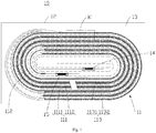
- the anode plate 111, the cathode plate 113 adjacent to the anode plate 111 and two layers of separator 112 adjacent to the anode plate 111 or the cathode plate 113 are defined as one layer of the electrode assembly 11 (referring to a K area in Fig. 1 , or referring to a K area in Fig. 2 ).
- a thickness a of the first current collector 1111 satisfies the following formula: 0.02T/(L+5) ⁇ c ⁇ a ⁇ (0.3L 2 )/(GT 2 ), which is calculated by numerical values of various parameters, where, T is a thickness of the cell 10 (in mm), c is a concentration of the lithium salt (in mol/L), G is a rigidity of the cell 10 in the width direction (in N/mm), and L is a number of layers of the electrode assembly 11.
- a thickness T of the cell 10 is 1 mm ⁇ 12 mm. In this embodiment, a thickness T of the cell 10 is 3 mm ⁇ 6 mm. In another embodiment, a thickness T of the cell 10 is 1 mm ⁇ 5 mm. In another embodiment, a thickness T of the cell 10 is 2 mm ⁇ 10 mm.
- a thickness a of the first current collector 1111 is 0.003 mm ⁇ 0.04 mm. In one embodiment, a thickness a of the first current collector 1111 is 0.003 mm ⁇ 0.02 mm. In another embodiment, a thickness a of the first current collector 1111 is 0.004 mm ⁇ 0.16 mm.
- a rigidity G of the cell 10 in a width direction is 50 N/mm ⁇ 400 N/mm. In one embodiment, a rigidity G of the cell 10 in a width direction is 100 N/mm ⁇ 400 N/mm. In another embodiment, a rigidity G of the cell 10 in a width direction is 50 N/mm ⁇ 200 N/mm. In a yet embodiment, a rigidity G of the cell 10 in a width direction is 100 N/mm ⁇ 300 N/mm.
- a concentration c of the lithium salt is 0.5 mol/L ⁇ 2 mol/L. In one embodiment, a concentration c of the lithium salt is 0.5 mol/L ⁇ 1.5 mol/L. In another embodiment, a concentration c of the lithium salt is 0.8 mol/L ⁇ 1.5 mol/L. In a yet embodiment, a concentration c of the lithium salt is 1.0 mol/L - 2.0 mol/L.
- the cathode plate 113 includes a second current collector 1131 and a second active substance layer 1132 arranged on the second current collector 1131.
- a transverse strength of the second current collector 1131 is 50 MPa - 300 MPa.
- a longitudinal strength of the second current collector 1131 is 50 MPa - 300 MPa.
- the second current collector 1131 includes one or more of elements, including Al, Ni, Mn, Cr, Cu, Fe, Mg, Si, Ti, Zr, V, Zn, Pb, S, P, Sn, As, Bi and Sb. Elements in the second current collector 1131 are tested by the ICP-OES test.
- the second active substance layer 1132 includes a second active substance and a second adhesive agent.
- a mass fraction of the second active substance is 96% - 99%.
- a mass fraction of the second adhesive agent is 0.5% - 2%.
- the second adhesive agent can be selected from, but not limited to one or more of copolymers of polyethylene oxide, polyvinylidene difluoride, butadiene styrene rubber, vinylidene fluoride and hexafluoropropylene.
- Monomer products produced from a test for the second adhesive agent by a pyrolysis gas chromatography mass spectroscopy (PY-GCMS), include one or more of butadiene, acrylonitrile, styrene, methyl methacrylate, butyl acrylate, vinyl pyrrolidone, ethylhexyl methacrylate, iso-octyl acrylate, polyvinylidine difluoride, 9-octadecenenitrile, propyl propionate, ethyl propionate, polyacrylic acid (PAA), N-methylpyrrolidone and 4-phenylcyclohexanone.
- PY-GCMS pyrolysis gas chromatography mass spectroscopy
- the second active substance layer 1132 includes a conductive agent.
- a mass fraction of the conductive agent is 0.5% ⁇ 2%.
- the conductive agent can be selected from, but not limited to one or more of acetylene black, carbon black, conductive carbon black (Super P), Ketjen black, single-walled carbon nanotube, multi-walled carbon nanotube, carbon nanofiber and graphene.
- the separator 112 includes one or more of polyethylene, polypropylene, polyvinylidine difluoride, modifiedpolyvinylidine difluoride, polyacrylate, modified polyacrylate, modified polyethylene, and modified polypropylene.
- An adhesive force between the separator 112 and the anode plate 111 is 0.5 N/m ⁇ 40 N/m.
- An adhesive force between the separator 112 and the cathode plate 113 is 0.5 N/m ⁇ 80 N/m.
- the cell 10 further includes a first tab 14 and a second tab 15.
- the first tab 14 is connected to the anode plate 111 and extends out of the package 12; the second tab 15 is connected to the cathode plate 113 and extends out of the package 12.
- the cell 10 includes an electrode assembly 11, a package 12 that receives the electrode assembly 11, an electrolyte solution 13, a first tab 14 and a second tab 15.
- the electrolyte solution 13 is received into the package 12.
- the electrolyte solution 13 includes a lithium salt.
- the electrode assembly 11 is formed by sequential winding or stacking of an anode plate 111, a separator 112 and a cathode plate 113.
- the first tab 14 is connected to the anode plate 111 and extends out of the package 12.
- the second tab 15 is connected to the cathode plate 113 and extends out of the package 12.
- the anode plate 111 includes a first current collector 1111 and a first active substance layer 1112 arranged on the first current collector 1111.
- a thickness T of the cell 10 is 3.3 mm.
- a number L of layers of the electrode assembly 11 is 11.
- a rigidity G of the cell 10 in a width direction is 86.6 N/mm.
- a concentration c of the lithium salt is 1.2 mol/L.
- a thickness a of the first current collector 1111 is 0.008 mm.
- the thickness a of the first current collector 1111 satisfies the following formula: 0.02 T/ L + 5 ⁇ c ⁇ a ⁇ 0.3 L 2 / GT 2 .
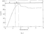
- the three point bending test includes the following steps: firstly, placing the cell 10 on two support points between which there is a certain spacing; next, applying downward force to the cell 10 above a central point between two support points by a pressure head (not shown); and then recording a displacement pressed by the pressure head and a load borne by the cell 10 corresponding to the displacement, and in this way, drawing a relational graph between the displacement pressed by the pressure head and the load borne by the cell 10 (referring to Fig. 4 ).
- an area A is an elastic deformation stage of the cell 10.
- the rigidity G of the cell 10 in the width direction is 86.6 N/mm by calculating a straight slope of a line segment in the area A.
- the cell 10 has a yield point in an area B; in an area C, all plates and the separator in the yielded cell 10 are separated or slide to increase the deformation, and the load borne by the cell 10 decreases.
- a heavy impact test (namely, impact test) is conducted for the cell 10 in Embodiment 1.
- the heavy impact test includes the following steps:
- the cell 10 in Embodiment 1 is subject to the blunt nail test.
- the blunt nail test includes the following steps: Firstly, charging the cell 10 to be in a 100% stage of charge (SOC) at a room temperature (25°C), wherein a voltage of the cell 10 is 4.4V; and then, referring to Fig. 5 , pressing a blunt nail 200 with a half-round head to a central place of the first tab 14 (for example, anode tab) within the package 12 in a length direction (Y-axis direction) at a lift speed of 300 N/min ⁇ 10 N/min, wherein test is stopped after pressure, applied to the cell 10, gradually rises to 1,300N from 0N. If a surface temperature of the cell 10, subject to the blunt nail test, is less than 200°C and the cell 10 does not smoke, fire and explode, the cell 10 is determined to pass the blunt nail test.
- Embodiment 2 differs from Embodiment 1 in that the thickness T of the cell 10 in Embodiment 2 is 4.5 mm, the number L of layers of the electrode assembly 11 is 13, the rigidity G of the cell 10 in the width direction is 95 N/mm, and the concentration c of the lithium salt is 1.0 mol/L.
- a thickness a of the first current collector 1111 is 0.006 mm. In Embodiment 2, the thickness a of the first current collector 1111 also satisfies the above-mentioned formula:
- Embodiment 3 differs from Embodiment 2 that the rigidity G of the cell 10 in the width direction in Embodiment 3 is 168 N/mm, and the concentration c of the lithium salt is 1.8 mol/L, and the thickness a of the first current collector 1111 is 0.012 mm.
- the thickness a of the first current collector 1111 also satisfies the above-mentioned formula.
- Embodiment 4 differs from Embodiment 2 in that the thickness T of the cell 10 in Embodiment 4 is 2.5 mm, the number L of layers of the electrode assembly 11 is 9, the rigidity G of the cell 10 in the width direction is 219 N/mm, and the thickness a of the first current collector 1111 is 0.016 mm.
- the thickness a of the first current collector 1111 also satisfies the above-mentioned formula.
- Embodiment 5 differs from Embodiment 1 in that the electrode assembly 11 in Embodiment 5 is formed by the sequential stacking of the anode plate 111, the separator 112 and the cathode plate 113.
- Embodiment 6 differs from Embodiment 2 in that the electrode assembly 11 in Embodiment 6 is formed by the sequential stacking of the anode plate 111, the separator 112 and the cathode plate 113.
- Embodiment 7 differs from Embodiment 3 in that the electrode assembly 11 in Embodiment 7 is formed by the sequential stacking of the anode plate 111, the separator 112 and the cathode plate 113.
- Embodiment 8 differs from Embodiment 4 in that the electrode assembly 11 in Embodiment 8 is formed by the sequential stacking of the anode plate 111, the separator 112 and the cathode plate 113.
- Contrast Example 1 differs from Embodiment 1 in that the thickness T of the cell 10 in Contrast Example 1 is 4.5 mm, the number L of layers of the electrode assembly 11 is 15, the rigidity G of the cell 10 in the width direction is 121 N/mm, and the concentration c of the lithium salt is 1.8 mol/L.
- a thickness a of the first current collector 1111 does not satisfy the above-mentioned formula.
- Contrast Example 2 differs from Embodiment 5 in that the thickness T of the cell 10 in Contrast Example 1 is 4.5 mm, the number L of layers of the electrode assembly 11 is 15, the rigidity G of the cell 10 in the width direction is 121 N/mm, and the concentration c of the lithium salt is 1.8 mol/L.
- a thickness a of the first current collector 1111 does not satisfy the above-mentioned formula.
- the thickness T of the cell 10 in Embodiment 1 is smaller than that in Contrast Example 1
- the number L of layers of the electrode assembly 11 in Embodiment 1 is smaller than that in Contrast Example 1
- the rigidity G of the cell 10 in the width direction in Embodiment 1 is obviously smaller than that in Contrast Example 1.
- the rigidity G of the cell 10 in the width direction is affected by the number L of layers of the electrode assembly 11 and the thickness T of the cell 10. The bigger the number of layers L of the electrode assembly 11 and the thickness T of the cell 10, the higher the rigidity G of the cell 10 in the width direction.
- the rigidity G of the cell 10 in the width direction can be obviously improved by increasing the thickness a of the first current collector 1111 under the premise of certain thickness T of the cell 10 and the number L of layers of the electrode assembly 11.
- the higher the rigidity G of the cell 10 in the width direction the smaller the deformation degree after the cell 10 suffers mechanical outer force (for instance: high speed impact, weight extrusion, and drop), a damaged fracture thereof will be more neat.
- a work process of the cell 10 is actually a redox reaction with lithium ions.
- This reaction is conducted by adding a certain amount of lithium salt into the electrolyte solution 13 so as to accelerate a redox reaction velocity, but the lithium salt will not be consumed in the redox reaction.
- heat from single short-circuit point in the cell 10, namely a magnitude of instantaneous current can be controlled by the lithium salt concentration.
- the concentration of the lithium salt is defined within the proper scope, which cannot only affect the performance of the cell 10 at normal work, but also decrease the redox reaction velocity during the short circuit, which ensures the using safety of the cell 10.
- the thickness a of the first current collector 1111, the thickness T of the cell 10, the rigidity G of the cell 10 and the concentration c of the lithium salt are defined to allow the thickness a of the first current collector 1111 to satisfy the relational expression of a, so that less short-circuit points are found in the cell 10 when the cell 10 is subject to the mechanical outer force, and the heat of single short-circuit point is low. Hence, even if the interior of the cell 10 is shortcircuited, the cell 10 will not have the problem that the heat is out of control due to excessive heat accumulated intermittently caused by the interior short circuit.
- the embodiments of the application further provide a battery.
- the battery includes a shell (not shown) and the cell 10.
- the cell 10 is received into the shell.
Landscapes
- Chemical & Material Sciences (AREA)
- Electrochemistry (AREA)
- General Chemical & Material Sciences (AREA)
- Chemical Kinetics & Catalysis (AREA)
- Engineering & Computer Science (AREA)
- Manufacturing & Machinery (AREA)
- Materials Engineering (AREA)
- Physics & Mathematics (AREA)
- Condensed Matter Physics & Semiconductors (AREA)
- General Physics & Mathematics (AREA)
- Inorganic Chemistry (AREA)
- Secondary Cells (AREA)
- Battery Electrode And Active Subsutance (AREA)
- Cell Electrode Carriers And Collectors (AREA)
Abstract
Description
- The application relates to the field of electrochemistry, in particular to a cell and a battery with the same.
- With the continuous increase of energy density and service voltage, the safety performance of a cell will gradually decline under the condition of external mechanical force (such as high-speed impact, heavy object squeeze and drop), exposing users to risks during use.
- In view of this, it is necessary to provide a cell with high mechanical strength to improve its safety performance.
- The embodiments of the application provide a cell, including an electrode assembly, a package accommodating the electrode assembly and an electrolyte solution, wherein the electrolyte solution is received in the package, the electrode assembly is formed by sequential winding or stacking of a cathode plate, a separator and an anode plate, the anode plate includes a first current collector and a first active substance layer arranged on the first current collector, the electrolyte solution includes a lithium salt, the anode plate, the cathode plate adjacent to the anode plate and two layers of the separator adjacent to the anode plate or the cathode plate are defined as one layer of the electrode assembly, and a thickness a (in mm) of the anode current collector satisfies the following formula: 0.02T/(L+5)×c≤a≤(0.3L2)/(GT2), which is calculated by numerical values of various parameters, wherein T is a thickness of the cell (in mm), c is a concentration of the lithium salt (in mol/L), G is a rigidity of the cell in a width direction (in N/mm), and L is a number of layers of the electrode assembly.
- In some embodiments, a thickness of the cell is 1 mm∼12 mm.
- In some embodiments, a thickness of the first current collector is 0.003 mm∼0.04 mm.
- In some embodiments, a rigidity of the cell in a width direction is 50 N/mm∼400 N/mm.
- In some embodiments, a concentration of the lithium salt is 0.5 mol/L∼2 mol/L.
- In some embodiments, a transverse strength of the first current collector is 50 MPa∼600 MPa.
- In some embodiments, a longitudinal strength of the first current collector is 50 MPa∼600 MPa.
- In some embodiments, the cathode plate includes a second current collector and a second active substance layer arranged on the second current collector, and a transverse strength of the second current collector is 50 MPa∼300 MPa.
- In some embodiments, a longitudinal strength of the second current collector is 50 MPa∼300 MPa.
- In some embodiments, the first active substance layer includes a first active substance and a first adhesive agent, a mass fraction of the first active substance is 97%∼99%, and a mass fraction of the first adhesive agent is 0.5%∼1.5%.
- In some embodiments, monomer products, produced from a test for the first adhesive agent by a pyrolysis gas chromatography mass spectroscopy (PY-GCMS), include one or more of butadiene, acrylonitrile, styrene, methyl methacrylate, butyl acrylate, vinyl pyrrolidone, ethylhexyl methacrylate, iso-octyl acrylate, polyvinylidene fluoride, 9-octadecenenitrile, propyl propionate, ethyl propionate, polyacrylic acid (PAA), N-methylpyrrolidone and 4-phenylcyclohexanone.
- In some embodiments, the second active substance layer includes a second active substance and a second adhesive agent, a mass fraction of the second active substance is 96%∼99%, and a mass fraction of the second adhesive agent is 0.5%∼2%.
- In some embodiments, the second adhesive agent includes one or more of copolymers of polyethylene oxide, polyvinylidene fluoride, butadiene styrene rubber, vinylidene fluoride and hexafluoropropylene.
- In some embodiments, monomer products, produced from a test for the second adhesive agent by a pyrolysis gas chromatography mass spectroscopy (PY-GCMS), include one or more of butadiene, acrylonitrile, styrene, methyl methacrylate, butyl acrylate, vinyl pyrrolidone, ethylhexyl methacrylate, iso-octyl acrylate, polyvinylidene fluoride, 9-octadecenenitrile, propyl propionate, ethyl propionate, polyacrylic acid (PAA), N-methylpyrrolidone and 4-phenylcyclohexanone.
- In some embodiments, the second active substance layer further includes a conductive agent, a mass fraction of which is 0.5% ∼ 2%.
- In some embodiments, the conductive agent includes one or more of acetylene black, carbon black, conductive carbon black (Super P), Ketjen black, single-walled carbon nanotube, multi-walled carbon nanotube, carbon nanofiber and graphene.
- In some embodiments, the first current collector includes one or more of elements, including Al, Ni, Mn, Cr, Cu, Fe, Mg, Si, Ti, Zr, V, Zn, Pb, S, P, Sn, As, Bi and Sb.
- In some embodiments, the second current collector includes one or more of elements, including Al, Ni, Mn, Cr, Cu, Fe, Mg, Si, Ti, Zr, V, Zn, Pb, S, P, Sn, As, Bi and Sb.
- In some embodiments, an adhesive force between the separator and the anode plate is 0.5 N/m ∼ 40 N/m.
- In some embodiments, an adhesive force between the separator and the cathode plate is 0.5 N/m ∼ 80 N/m.
- In some embodiments, the separator includes one or more of polyethylene, polypropylene, polyvinylidine difluoride, modifiedpolyvinylidine difluoride, polyacrylate, modified polyacrylate, modified polyethylene and modified polypropylene.
- The embodiments of the application further provide a battery, the battery includes a shell and the aforesaid cell, the cell is received into the shell.
- In conclusion, according to the cell of the application, the thickness a of the first current collector satisfies the relational expression by adjusting the thickness a of the first current collector, the thickness T of the cell, the rigidity G of the cell, the number L of layers of the electrode assembly and the concentration c of the lithium salt, thereby greatly improving the mechanical strength of the cell, and thus improving the safety performance of the cell.
-
-
Fig. 1 is a schematic view of a cell in one embodiment of the application. -
Fig. 2 is a schematic view of a cell in another embodiment of the application. -
Fig. 3 is a schematic plan view of a cell shown inFig. 1 . -
Fig. 4 is a relational graph between a pressing displacement of a pressure head and a load borne by the cell. -
Fig. 5 is a schematic plan view of a cell shown inFig. 3 in a blunt nail crush test. - The application will be further described in the following detailed description of the embodiments with reference to the above drawings.
- The technical solutions in the embodiments of the application will be clearly and completely described below in conjunction with the drawings in the embodiments of the application. Obviously, the described embodiments are only some, not all of the embodiments of the application. Based on the embodiments herein, all other embodiments obtained by those of ordinary skill in the art without any creative work also fall into the protection scope of the application.
- Unless otherwise defined, all technical and scientific terms used herein have the same meaning as those generally understood by those skilled in the art belonging to the technical field of the application. All terms used in the Description of the application only aim to describe the specific embodiments and are not intended to limit the application.
- Some embodiments of the application are elaborated in conjunction with the accompanying drawings. Without conflict, the following embodiments and features in these embodiments can be combined with each other.
- Referring to
Fig. 1 , an embodiment of the application provides acell 10. Thecell 10 includes anelectrode assembly 11, apackage 12 that receives theelectrode assembly 11 and anelectrolyte solution 13. Theelectrolyte solution 13 is received into thepackage 12. Theelectrolyte solution 13 includes a lithium salt. In other embodiments, theelectrolyte solution 13 may further include some common organic solvents, for example, ethylene carbonate, propylene carbonate, ethyl methyl carbonate and diethyl carbonate. - Referring to
Figs. 1 and2 , theelectrode assembly 11 is formed by sequential winding or stacking of ananode plate 111, aseparator 112 and acathode plate 113. - In some embodiments, the
anode plate 111 includes a firstcurrent collector 1111 and a firstactive substance layer 1112 arranged on the firstcurrent collector 1111. A transverse strength of the firstcurrent collector 1111 is 50 MPa ∼ 600 MPa. A longitudinal strength of the firstcurrent collector 1111 is 50 MPa ∼ 600 MPa. The firstcurrent collector 1111 includes one or more of elements, including Al, Ni, Mn, Cr, Cu, Fe, Mg, Si, Ti, Zr, V, Zn, Pb, S, P, Sn, As, Bi and Sb. Elements in the firstcurrent collector 1111 can be tested by an inductively coupled plasma-optical emission spectrometry (ICP-OES). - In one embodiment, the first
active substance layer 1112 includes a first active substance and a first adhesive agent. A mass fraction of the first active substance is 97% ∼ 99%. A mass fraction of the first adhesive agent is 0.5% ∼ 1.5%. Monomer products, produced from a test for the first adhesive agent by a pyrolysis gas chromatography mass spectroscopy (PY-GCMS), include one or more of butadiene, acrylonitrile, styrene, methyl methacrylate, butyl acrylate, vinyl pyrrolidone, ethylhexyl methacrylate, iso-octyl acrylate, polyvinylidine difluoride, 9-octadecenenitrile, propyl propionate, ethyl propionate, polyacrylic acid (PAA), N-methylpyrrolidone and 4-phenylcyclohexanone. - In this embodiment, the
anode plate 111, thecathode plate 113 adjacent to theanode plate 111 and two layers ofseparator 112 adjacent to theanode plate 111 or thecathode plate 113 are defined as one layer of the electrode assembly 11 (referring to a K area inFig. 1 , or referring to a K area inFig. 2 ). A thickness a of the firstcurrent collector 1111 satisfies the following formula: 0.02T/(L+5)×c≤a≤(0.3L2)/(GT2), which is calculated by numerical values of various parameters, where, T is a thickness of the cell 10 (in mm), c is a concentration of the lithium salt (in mol/L), G is a rigidity of thecell 10 in the width direction (in N/mm), and L is a number of layers of theelectrode assembly 11. - In this embodiment, a thickness T of the
cell 10 is 1 mm ∼ 12 mm. In this embodiment, a thickness T of thecell 10 is 3 mm ∼ 6 mm. In another embodiment, a thickness T of thecell 10 is 1 mm ∼ 5 mm. In another embodiment, a thickness T of thecell 10 is 2 mm ∼ 10 mm. - In another embodiment, a thickness a of the first
current collector 1111 is 0.003 mm ∼ 0.04 mm. In one embodiment, a thickness a of the firstcurrent collector 1111 is 0.003 mm ∼ 0.02 mm. In another embodiment, a thickness a of the firstcurrent collector 1111 is 0.004 mm ∼ 0.16 mm. - In this embodiment, a rigidity G of the
cell 10 in a width direction is 50 N/mm ∼ 400 N/mm. In one embodiment, a rigidity G of thecell 10 in a width direction is 100 N/mm ∼ 400 N/mm. In another embodiment, a rigidity G of thecell 10 in a width direction is 50 N/mm ∼ 200 N/mm. In a yet embodiment, a rigidity G of thecell 10 in a width direction is 100 N/mm ∼ 300 N/mm. - In this embodiment, a concentration c of the lithium salt is 0.5 mol/L ∼ 2 mol/L. In one embodiment, a concentration c of the lithium salt is 0.5 mol/L ∼ 1.5 mol/L. In another embodiment, a concentration c of the lithium salt is 0.8 mol/L ∼ 1.5 mol/L. In a yet embodiment, a concentration c of the lithium salt is 1.0 mol/L - 2.0 mol/L.
- In this embodiment, the
cathode plate 113 includes a secondcurrent collector 1131 and a secondactive substance layer 1132 arranged on the secondcurrent collector 1131. A transverse strength of the secondcurrent collector 1131 is 50 MPa - 300 MPa. A longitudinal strength of the secondcurrent collector 1131 is 50 MPa - 300 MPa. The secondcurrent collector 1131 includes one or more of elements, including Al, Ni, Mn, Cr, Cu, Fe, Mg, Si, Ti, Zr, V, Zn, Pb, S, P, Sn, As, Bi and Sb. Elements in the secondcurrent collector 1131 are tested by the ICP-OES test. - The second
active substance layer 1132 includes a second active substance and a second adhesive agent. A mass fraction of the second active substance is 96% - 99%. A mass fraction of the second adhesive agent is 0.5% - 2%. The second adhesive agent can be selected from, but not limited to one or more of copolymers of polyethylene oxide, polyvinylidene difluoride, butadiene styrene rubber, vinylidene fluoride and hexafluoropropylene. Monomer products, produced from a test for the second adhesive agent by a pyrolysis gas chromatography mass spectroscopy (PY-GCMS), include one or more of butadiene, acrylonitrile, styrene, methyl methacrylate, butyl acrylate, vinyl pyrrolidone, ethylhexyl methacrylate, iso-octyl acrylate, polyvinylidine difluoride, 9-octadecenenitrile, propyl propionate, ethyl propionate, polyacrylic acid (PAA), N-methylpyrrolidone and 4-phenylcyclohexanone. - Furthermore, the second
active substance layer 1132 includes a conductive agent. A mass fraction of the conductive agent is 0.5% ∼ 2%. The conductive agent can be selected from, but not limited to one or more of acetylene black, carbon black, conductive carbon black (Super P), Ketjen black, single-walled carbon nanotube, multi-walled carbon nanotube, carbon nanofiber and graphene. - In some embodiments, the
separator 112 includes one or more of polyethylene, polypropylene, polyvinylidine difluoride, modifiedpolyvinylidine difluoride, polyacrylate, modified polyacrylate, modified polyethylene, and modified polypropylene. An adhesive force between theseparator 112 and theanode plate 111 is 0.5 N/m ∼ 40 N/m. An adhesive force between theseparator 112 and thecathode plate 113 is 0.5 N/m ∼ 80 N/m. - Furthermore, referring to
Figs. 1 ,2 and3 , thecell 10 further includes afirst tab 14 and asecond tab 15. In some embodiments, thefirst tab 14 is connected to theanode plate 111 and extends out of thepackage 12; thesecond tab 15 is connected to thecathode plate 113 and extends out of thepackage 12. - The following paragraphs will elaborate the
cell 10 of the application by virtue of embodiments and contrast Examples. - Referring to
Fig. 1 , thecell 10 includes anelectrode assembly 11, apackage 12 that receives theelectrode assembly 11, anelectrolyte solution 13, afirst tab 14 and asecond tab 15. Theelectrolyte solution 13 is received into thepackage 12. Theelectrolyte solution 13 includes a lithium salt. - The
electrode assembly 11 is formed by sequential winding or stacking of ananode plate 111, aseparator 112 and acathode plate 113. Thefirst tab 14 is connected to theanode plate 111 and extends out of thepackage 12. thesecond tab 15 is connected to thecathode plate 113 and extends out of thepackage 12. Theanode plate 111 includes a firstcurrent collector 1111 and a firstactive substance layer 1112 arranged on the firstcurrent collector 1111. - In this embodiment, a thickness T of the
cell 10 is 3.3 mm. A number L of layers of theelectrode assembly 11 is 11. A rigidity G of thecell 10 in a width direction is 86.6 N/mm. A concentration c of the lithium salt is 1.2 mol/L. A thickness a of the firstcurrent collector 1111 is 0.008 mm. In Embodiment 1, the thickness a of the firstcurrent collector 1111 satisfies the following formula:
cell 10 in a width direction (namely a dotted line X direction inFig. 3 ) is tested by a three point bending test. The three point bending test includes the following steps:
firstly, placing thecell 10 on two support points between which there is a certain spacing; next, applying downward force to thecell 10 above a central point between two support points by a pressure head (not shown); and then recording a displacement pressed by the pressure head and a load borne by thecell 10 corresponding to the displacement, and in this way, drawing a relational graph between the displacement pressed by the pressure head and the load borne by the cell 10 (referring toFig. 4 ). - Referring to
Fig. 4 , an area A is an elastic deformation stage of thecell 10. The rigidity G of thecell 10 in the width direction is 86.6 N/mm by calculating a straight slope of a line segment in the area A. Continuously referring toFig. 4 , thecell 10 has a yield point in an area B; in an area C, all plates and the separator in the yieldedcell 10 are separated or slide to increase the deformation, and the load borne by thecell 10 decreases. - A heavy impact test (namely, impact test) is conducted for the
cell 10 in Embodiment 1. The heavy impact test includes the following steps: - Firstly, charging the
cell 10 to be in a 100% stage of charge (SOC) at a room temperature (25°C), - wherein a voltage of the
cell 10 is 4.4 V; next, placing thecell 10 on a platform, and then transversely placing a metal bar with a diameter of 15.8 mm (for example, iron bar) on a geometric center of thecell 10; and then using a heavy hammer with a mass of 9.1 kg to impact a surface, placed with the metal bar, of thecell 10 in a free falling state from 610 mm, and stopping the test after a surface temperature of thecell 10 drops to room temperature. If thecell 10, after being subject to the heavy impact test, has no fire or explosion, thecell 10 is determined to pass the heavy impact test. - The
cell 10 in Embodiment 1 is subject to the blunt nail test. The blunt nail test includes the following steps:
Firstly, charging thecell 10 to be in a 100% stage of charge (SOC) at a room temperature (25°C), wherein a voltage of thecell 10 is 4.4V; and then, referring toFig. 5 , pressing ablunt nail 200 with a half-round head to a central place of the first tab 14 (for example, anode tab) within thepackage 12 in a length direction (Y-axis direction) at a lift speed of 300 N/min±10 N/min, wherein test is stopped after pressure, applied to thecell 10, gradually rises to 1,300N from 0N. If a surface temperature of thecell 10, subject to the blunt nail test, is less than 200°C and thecell 10 does not smoke, fire and explode, thecell 10 is determined to pass the blunt nail test. -
Embodiment 2 differs from Embodiment 1 in that the thickness T of thecell 10 inEmbodiment 2 is 4.5 mm, the number L of layers of theelectrode assembly 11 is 13, the rigidity G of thecell 10 in the width direction is 95 N/mm, and the concentration c of the lithium salt is 1.0 mol/L. A thickness a of the firstcurrent collector 1111 is 0.006 mm. InEmbodiment 2, the thickness a of the firstcurrent collector 1111 also satisfies the above-mentioned formula: -
Embodiment 3 differs fromEmbodiment 2 that the rigidity G of thecell 10 in the width direction inEmbodiment 3 is 168 N/mm, and the concentration c of the lithium salt is 1.8 mol/L, and the thickness a of the firstcurrent collector 1111 is 0.012 mm. InEmbodiment 3, the thickness a of the firstcurrent collector 1111 also satisfies the above-mentioned formula. -
Embodiment 4 differs fromEmbodiment 2 in that the thickness T of thecell 10 inEmbodiment 4 is 2.5 mm, the number L of layers of theelectrode assembly 11 is 9, the rigidity G of thecell 10 in the width direction is 219 N/mm, and the thickness a of the firstcurrent collector 1111 is 0.016 mm. InEmbodiment 4, the thickness a of the firstcurrent collector 1111 also satisfies the above-mentioned formula. -
Embodiment 5 differs from Embodiment 1 in that theelectrode assembly 11 inEmbodiment 5 is formed by the sequential stacking of theanode plate 111, theseparator 112 and thecathode plate 113. - Embodiment 6 differs from
Embodiment 2 in that theelectrode assembly 11 in Embodiment 6 is formed by the sequential stacking of theanode plate 111, theseparator 112 and thecathode plate 113. - Embodiment 7 differs from
Embodiment 3 in that theelectrode assembly 11 in Embodiment 7 is formed by the sequential stacking of theanode plate 111, theseparator 112 and thecathode plate 113. - Embodiment 8 differs from
Embodiment 4 in that theelectrode assembly 11 in Embodiment 8 is formed by the sequential stacking of theanode plate 111, theseparator 112 and thecathode plate 113. - Contrast Example 1 differs from Embodiment 1 in that the thickness T of the
cell 10 in Contrast Example 1 is 4.5 mm, the number L of layers of theelectrode assembly 11 is 15, the rigidity G of thecell 10 in the width direction is 121 N/mm, and the concentration c of the lithium salt is 1.8 mol/L. In Contrast Example 1, a thickness a of the firstcurrent collector 1111 does not satisfy the above-mentioned formula. - Contrast Example 2 differs from
Embodiment 5 in that the thickness T of thecell 10 in Contrast Example 1 is 4.5 mm, the number L of layers of theelectrode assembly 11 is 15, the rigidity G of thecell 10 in the width direction is 121 N/mm, and the concentration c of the lithium salt is 1.8 mol/L. In Contrast Example 2, a thickness a of the firstcurrent collector 1111 does not satisfy the above-mentioned formula. - The preparation conditions and corresponding test results of Embodiments 1-8 and Contrast Examples 1-2 are listed in Table 1 below.
Table 1 Preparation Conditions and Corresponding Test Results of Embodiments 1-8 and Contrast Examples 1-2 Type of cell Thickness of cell, T (mm) Number of layers of electrode assembly, L (layer) Thickness of first current collector, a (mm) Rigidity of cell in a width direction, G (N/mm) Concentration of lithium salt, c (mol/L) Whether a thickness a of the first current collector satisfies this relational expression Pass rate of heavy impact test Pass rate of blunt nail test Embodiment 1 Wound 3.3 11 0.008 86.6 1.2 Yes 100% 100 % Embodiment 2 Wound 4.5 13 0.006 95 1.0 Yes 100% 100 % Embodiment 3 Wound 4.5 13 0.012 168 1.8 Yes 100% 100 % Embodiment 4 Wound 2.5 9 0.016 219 1.0 Yes 100% 100 % Embodiment 5 Stacked 3.3 11 0.008 86.6 1.2 Yes 100% 100% Embodiment 6 Stacked 4.5 13 0.006 95 1.0 Yes 100% 100% Embodiment 7 Stacked 4.5 13 0.012 168 1.8 Yes 100% 100% Embodiment 8 Stacked 2.5 9 0.016 219 1.0 Yes 100% 100% Contrast Example 1 Wound 4.5 15 0.008 121 1.8 No 65% 90% Contrast Example 2 Stacked 4.5 15 0.008 121 1.8 No 65% 90% - Referring to Table 1, it can be seen, from the comparison between
Embodiment 2 and Contrast Example 1, that the number L of layers of theelectrode assembly 11 is smaller than that in Contrast Example 1, the thickness a of the firstcurrent collector 1111 inEmbodiment 2 is smaller than that in Contrast Example 1, and the rigidity G of thecell 10 in the width direction inEmbodiment 2 is obviously smaller than that in Contrast Example 1. As can be seen, when the thickness T of thecell 10 is certain, the rigidity G of thecell 10 in the width direction is affected by the number L of layers of theelectrode assembly 11 and the thickness a of the firstcurrent collector 1111. The bigger the number of layers L of theelectrode assembly 11 and the thickness a of the firstcurrent collector 1111, the higher the rigidity G of thecell 10 in the width direction. - It can be seen, from the comparison between
Embodiment 3 and Contrast Example 1, that the number L of layers of theelectrode assembly 11 inEmbodiment 3 is smaller than that in Contrast Example 1, the thickness a of the firstcurrent collector 1111 inEmbodiment 3 is smaller than that in Contrast Example 1, and the rigidity G of thecell 10 in the width direction inEmbodiment 3 is obviously smaller than that in Contrast Example 1. As can be seen, when the thickness T of thecell 10 is certain, the rigidity G of thecell 10 in the width direction, relative to the number L of layers of theelectrode assembly 11, is easier affected by the thickness a of the firstcurrent collector 1111. Besides, relative to Contrast Example 1, when the concentration c of the lithium salt inEmbodiment 3 is consistent with the one in Contrast Example 1, the rigidity G of thecell 10 in the width direction can be improved within a certain scope, and the pass rate of thecell 10 in the heavy impact and blunt nail tests can be improved obviously. - It can be seen, from the comparison between Embodiment 1 and Contrast Example 1, that the thickness T of the
cell 10 in Embodiment 1 is smaller than that in Contrast Example 1, and the number L of layers of theelectrode assembly 11 in Embodiment 1 is smaller than that in Contrast Example 1, while the rigidity G of thecell 10 in the width direction in Embodiment 1 is obviously smaller than that in Contrast Example 1. As can be seen, when the thickness a of the firstcurrent collector 1111 is certain, the rigidity G of thecell 10 in the width direction is affected by the number L of layers of theelectrode assembly 11 and the thickness T of thecell 10. The bigger the number of layers L of theelectrode assembly 11 and the thickness T of thecell 10, the higher the rigidity G of thecell 10 in the width direction. - It can be seen, from the comparison between
Embodiments cell 10 in the width direction can be obviously improved by increasing the thickness a of the firstcurrent collector 1111 under the premise of certain thickness T of thecell 10 and the number L of layers of theelectrode assembly 11. The higher the rigidity G of thecell 10 in the width direction, the smaller the deformation degree after thecell 10 suffers mechanical outer force (for instance: high speed impact, weight extrusion, and drop), a damaged fracture thereof will be more neat. Hence, the higher a probability that theanode plate 111 is in contact with thecathode plate 113, the smaller the number of short-circuit points, so that the using safety of thecell 10 is greatly improved. Besides, it can be understood that a work process of thecell 10 is actually a redox reaction with lithium ions. This reaction is conducted by adding a certain amount of lithium salt into theelectrolyte solution 13 so as to accelerate a redox reaction velocity, but the lithium salt will not be consumed in the redox reaction. Hence, heat from single short-circuit point in thecell 10, namely a magnitude of instantaneous current, can be controlled by the lithium salt concentration. In this way, the concentration of the lithium salt is defined within the proper scope, which cannot only affect the performance of thecell 10 at normal work, but also decrease the redox reaction velocity during the short circuit, which ensures the using safety of thecell 10. - It can be seen from,
Embodiments 1 and 5, Embodiments 2 and 6, Embodiments 3 and 7 and Embodiments 4 and 8, that the thickness T of thecell 10, the number L of layers of theelectrode assembly 11, the rigidity G of thecell 10 in the width direction, the concentration c of the lithium salt and the thickness a of the firstcurrent collector 1111 will not affect the overall mechanical performance of thecell 10 when the type of thecell 10 is changed under certain circumstances. - In view of the above, the thickness a of the first
current collector 1111, the thickness T of thecell 10, the rigidity G of thecell 10 and the concentration c of the lithium salt are defined to allow the thickness a of the firstcurrent collector 1111 to satisfy the relational expression of a, so that less short-circuit points are found in thecell 10 when thecell 10 is subject to the mechanical outer force, and the heat of single short-circuit point is low. Hence, even if the interior of thecell 10 is shortcircuited, thecell 10 will not have the problem that the heat is out of control due to excessive heat accumulated intermittently caused by the interior short circuit. - Besides, the embodiments of the application further provide a battery. The battery includes a shell (not shown) and the
cell 10. Thecell 10 is received into the shell. - The above embodiments are merely used to illustrate, instead of limiting, the technical solution of the application. Although the application is elaborated with reference to the preferred embodiments, those of ordinary skill in the art should understood to amend or equivalently replace the technical solution of the application without departure from the spirit and essential characteristics thereof.
| Cell |
| 10 | |
| |
11 |
| |
111 |
| First |
1111 |
| First |
1112 |
| Separator | 112 |
| |
113 |
| Second |
1131 |
| Second |
1132 |
| |
12 |
| |
13 |
| |
14 |
| |
15 |
| |
200 |
Claims (10)
- A cell, comprising an electrode assembly, a package that receives the electrode assembly and an electrolyte solution, the electrolyte solution being received into the package, the electrode assembly being formed by sequential winding or stacking of an anode plate, a separator and a cathode plate, the anode plate comprising a first current collector and a first active substance layer arranged on the first current collector, the electrolyte solution comprising a lithium salt,
characterized in that the anode plate, the cathode plate adjacent to the anode plate and two layers of the separator adjacent to the anode plate or the cathode plate are defined as one layer of the electrode assembly; a thickness a of the anode current collector satisfies the following formula: 0.02T/(L+5)×c≤a≤(0.3L2)/(GT2), which is calculated by numerical values of various parameters; wherein T is a thickness of the cell (in mm), c is a concentration of the lithium salt (in mol/L), G is a rigidity of the cell in a width direction (in N/mm), and L is a number of layers of the electrode assembly. - The cell according to claim 1, characterized in that a thickness of the cell is 1 mm ∼ 12 mm.
- The cell according to claim 1, characterized in that a thickness of the first current collector is 0.003 mm ∼ 0.04 mm.
- The cell according to claim 1, characterized in that a rigidity of the cell in a width direction is 50 N/mm ∼ 400 N/mm.
- The cell according to claim 1, characterized in that a concentration of the lithium salt is 0.5 mol/L ∼ 2 mol/L.
- The cell according to claim 1, characterized in that a transverse strength of the first current collector is 50 MPa ∼ 600 MPa.
- The cell according to claim 1, characterized in that a longitudinal strength of the first current collector is 50 MPa ∼ 600 MPa.
- The cell according to claim 1, characterized in that the cathode plate comprises a second current collector and a second active substance layer arranged on the second current collector, and a transverse strength of the second current collector is 50 MPa ∼ 300 MPa.
- The cell according to claim 8, characterized in that a longitudinal strength of the second current collector is 50 MPa ∼ 300 MPa.
- A battery, comprising a shell, characterized in that the battery comprises the cell according to any one of claims 1-9, and the cell is received into the shell.
Applications Claiming Priority (1)
| Application Number | Priority Date | Filing Date | Title |
|---|---|---|---|
| PCT/CN2020/078645 WO2021179172A1 (en) | 2020-03-10 | 2020-03-10 | Cell and battery having said cell |
Publications (2)
| Publication Number | Publication Date |
|---|---|
| EP3907787A1 true EP3907787A1 (en) | 2021-11-10 |
| EP3907787A4 EP3907787A4 (en) | 2022-06-22 |
Family
ID=75699549
Family Applications (1)
| Application Number | Title | Priority Date | Filing Date |
|---|---|---|---|
| EP20864326.2A Pending EP3907787A4 (en) | 2020-03-10 | 2020-03-10 | Cell and battery having said cell |
Country Status (3)
| Country | Link |
|---|---|
| EP (1) | EP3907787A4 (en) |
| CN (1) | CN112771698B (en) |
| WO (1) | WO2021179172A1 (en) |
Families Citing this family (2)
| Publication number | Priority date | Publication date | Assignee | Title |
|---|---|---|---|---|
| CN113258121B (en) * | 2021-05-17 | 2022-07-12 | 湖北亿纬动力有限公司 | Method for calculating width of winding type bare cell after hot pressing |
| CN113903969B (en) * | 2021-09-23 | 2022-07-08 | 宁德新能源科技有限公司 | Battery cell and power utilization device |
Family Cites Families (7)
| Publication number | Priority date | Publication date | Assignee | Title |
|---|---|---|---|---|
| JP4551539B2 (en) * | 2000-07-28 | 2010-09-29 | 株式会社東芝 | Nonaqueous electrolyte secondary battery |
| US7955731B2 (en) * | 2006-08-14 | 2011-06-07 | Sony Corporation | Nonaqueous electrolyte secondary cell |
| KR101118259B1 (en) * | 2009-06-05 | 2012-03-20 | 삼성에스디아이 주식회사 | Electrode assembly and secondary battery using the same |
| WO2013031195A1 (en) * | 2011-08-29 | 2013-03-07 | パナソニック株式会社 | Thin battery electrode group, thin battery, and electronic device |
| CN203013803U (en) * | 2012-11-06 | 2013-06-19 | 博科能源系统(深圳)有限公司 | Lithium battery encapsulation structure and lithium battery |
| CN104064697A (en) * | 2014-07-16 | 2014-09-24 | 奇瑞汽车股份有限公司 | Composite lithium battery packaging film material and preparation method thereof |
| KR102669086B1 (en) * | 2016-04-04 | 2024-05-24 | 삼성에스디아이 주식회사 | Secondary battery |
-
2020
- 2020-03-10 CN CN202080005330.3A patent/CN112771698B/en active Active
- 2020-03-10 EP EP20864326.2A patent/EP3907787A4/en active Pending
- 2020-03-10 WO PCT/CN2020/078645 patent/WO2021179172A1/en not_active Ceased
Also Published As
| Publication number | Publication date |
|---|---|
| CN112771698B (en) | 2022-02-22 |
| EP3907787A4 (en) | 2022-06-22 |
| CN112771698A (en) | 2021-05-07 |
| WO2021179172A1 (en) | 2021-09-16 |
Similar Documents
| Publication | Publication Date | Title |
|---|---|---|
| US20250054989A1 (en) | Positive electrode plate and electrochemical device | |
| JP6791127B2 (en) | Binder composition for positive electrode of lithium ion secondary battery, slurry composition for positive electrode of lithium ion secondary battery, positive electrode for lithium ion secondary battery and lithium | |
| EP2827411B1 (en) | Liquid lead-acid battery and idling stop vehicle using liquid lead-acid battery | |
| EP3852179A1 (en) | Laminated body for secondary batteries and secondary battery, and manufacturing methods for same | |
| US10727533B2 (en) | Fluoride ion battery and method for producing fluoride ion battery | |
| WO2020098743A1 (en) | Battery | |
| KR20080095166A (en) | Manufacturing method of square flat secondary battery | |
| CN102224629A (en) | Rectangular nonaqueous electrolyte secondary battery and method for manufacturing same | |
| EP3690993B1 (en) | Compositions for forming a porous insulating layer, electrode for non-aqueous electrolyte rechargeable battery, rechargeable battery including the electrode and method of manufacturing the electrode | |
| US11196044B2 (en) | Positive electrode plate and electrochemical device | |
| EP3787069A1 (en) | Positive pole piece and electrochemical apparatus | |
| EP4027427A1 (en) | All solid state battery | |
| CN113839028A (en) | Positive electrode and battery | |
| EP3907796A1 (en) | Cell and battery having said cell | |
| KR20140048615A (en) | Press device for jelly roll-secondary battery and fabricating method of secondary battery using the same | |
| KR102754050B1 (en) | Unit stack-cell structure and all-solid secondary battery including the same | |
| US20240222687A1 (en) | Lithium Secondary Battery | |
| EP3035410A1 (en) | Secondary battery including low resistance electrode tab | |
| EP2639864B1 (en) | Lithium secondary battery | |
| CN112771698B (en) | Battery cell and battery with same | |
| CN211858799U (en) | Battery cell and battery with same | |
| JP2011082093A (en) | Flat type nonaqueous electrolyte secondary battery | |
| JP5061433B2 (en) | Current collector and lithium ion secondary battery using the same | |
| CN1297034C (en) | Nonaqueous electrolyte and secondary cell using the same | |
| EP4496023A1 (en) | Non-aqueous electrolyte secondary battery |
Legal Events
| Date | Code | Title | Description |
|---|---|---|---|
| STAA | Information on the status of an ep patent application or granted ep patent |
Free format text: STATUS: UNKNOWN |
|
| STAA | Information on the status of an ep patent application or granted ep patent |
Free format text: STATUS: THE INTERNATIONAL PUBLICATION HAS BEEN MADE |
|
| PUAI | Public reference made under article 153(3) epc to a published international application that has entered the european phase |
Free format text: ORIGINAL CODE: 0009012 |
|
| STAA | Information on the status of an ep patent application or granted ep patent |
Free format text: STATUS: REQUEST FOR EXAMINATION WAS MADE |
|
| 17P | Request for examination filed |
Effective date: 20210326 |
|
| AK | Designated contracting states |
Kind code of ref document: A1 Designated state(s): AL AT BE BG CH CY CZ DE DK EE ES FI FR GB GR HR HU IE IS IT LI LT LU LV MC MK MT NL NO PL PT RO RS SE SI SK SM TR |
|
| REG | Reference to a national code |
Ref country code: DE Ref legal event code: R079 Free format text: PREVIOUS MAIN CLASS: H01M0004130000 Ipc: H01M0004700000 |
|
| A4 | Supplementary search report drawn up and despatched |
Effective date: 20220519 |
|
| RIC1 | Information provided on ipc code assigned before grant |
Ipc: H01M 10/0525 20100101ALI20220513BHEP Ipc: H01M 10/04 20060101ALI20220513BHEP Ipc: H01M 4/70 20060101AFI20220513BHEP |
|
| DAV | Request for validation of the european patent (deleted) | ||
| DAX | Request for extension of the european patent (deleted) | ||
| STAA | Information on the status of an ep patent application or granted ep patent |
Free format text: STATUS: EXAMINATION IS IN PROGRESS |
|
| 17Q | First examination report despatched |
Effective date: 20250305 |