EP3907717A1 - Alarm system component with event detection while being unpowered - Google Patents
Alarm system component with event detection while being unpowered Download PDFInfo
- Publication number
- EP3907717A1 EP3907717A1 EP20382382.8A EP20382382A EP3907717A1 EP 3907717 A1 EP3907717 A1 EP 3907717A1 EP 20382382 A EP20382382 A EP 20382382A EP 3907717 A1 EP3907717 A1 EP 3907717A1
- Authority
- EP
- European Patent Office
- Prior art keywords
- component
- monitoring module
- event
- occurrence
- read request
- Prior art date
- Legal status (The legal status is an assumption and is not a legal conclusion. Google has not performed a legal analysis and makes no representation as to the accuracy of the status listed.)
- Granted
Links
Images
Classifications
-
- G—PHYSICS
- G08—SIGNALLING
- G08B—SIGNALLING SYSTEMS, e.g. PERSONAL CALLING SYSTEMS; ORDER TELEGRAPHS; ALARM SYSTEMS
- G08B29/00—Checking or monitoring of signalling or alarm systems; Prevention or correction of operating errors, e.g. preventing unauthorised operation
- G08B29/12—Checking intermittently signalling or alarm systems
- G08B29/14—Checking intermittently signalling or alarm systems checking the detection circuits
-
- G—PHYSICS
- G06—COMPUTING OR CALCULATING; COUNTING
- G06K—GRAPHICAL DATA READING; PRESENTATION OF DATA; RECORD CARRIERS; HANDLING RECORD CARRIERS
- G06K19/00—Record carriers for use with machines and with at least a part designed to carry digital markings
- G06K19/06—Record carriers for use with machines and with at least a part designed to carry digital markings characterised by the kind of the digital marking, e.g. shape, nature, code
- G06K19/067—Record carriers with conductive marks, printed circuits or semiconductor circuit elements, e.g. credit or identity cards also with resonating or responding marks without active components
- G06K19/07—Record carriers with conductive marks, printed circuits or semiconductor circuit elements, e.g. credit or identity cards also with resonating or responding marks without active components with integrated circuit chips
- G06K19/0723—Record carriers with conductive marks, printed circuits or semiconductor circuit elements, e.g. credit or identity cards also with resonating or responding marks without active components with integrated circuit chips the record carrier comprising an arrangement for non-contact communication, e.g. wireless communication circuits on transponder cards, non-contact smart cards or RFIDs
-
- G—PHYSICS
- G01—MEASURING; TESTING
- G01K—MEASURING TEMPERATURE; MEASURING QUANTITY OF HEAT; THERMALLY-SENSITIVE ELEMENTS NOT OTHERWISE PROVIDED FOR
- G01K3/00—Thermometers giving results other than momentary value of temperature
- G01K3/005—Circuits arrangements for indicating a predetermined temperature
-
- G—PHYSICS
- G06—COMPUTING OR CALCULATING; COUNTING
- G06K—GRAPHICAL DATA READING; PRESENTATION OF DATA; RECORD CARRIERS; HANDLING RECORD CARRIERS
- G06K17/00—Methods or arrangements for effecting co-operative working between equipments covered by two or more of main groups G06K1/00 - G06K15/00, e.g. automatic card files incorporating conveying and reading operations
- G06K17/0022—Methods or arrangements for effecting co-operative working between equipments covered by two or more of main groups G06K1/00 - G06K15/00, e.g. automatic card files incorporating conveying and reading operations arrangements or provisions for transferring data to distant stations, e.g. from a sensing device
-
- G—PHYSICS
- G06—COMPUTING OR CALCULATING; COUNTING
- G06K—GRAPHICAL DATA READING; PRESENTATION OF DATA; RECORD CARRIERS; HANDLING RECORD CARRIERS
- G06K7/00—Methods or arrangements for sensing record carriers, e.g. for reading patterns
- G06K7/0008—General problems related to the reading of electronic memory record carriers, independent of its reading method, e.g. power transfer
Definitions
- the present disclosure relates to a component for use in an alarm system, and particularly to a technique for detecting events when the component is unpowered.
- An alarm system such as a fire alarm system or an intrusion alarm system, comprises a variety of components working in unison to detect and warn people in the event that a change in an environmental parameter has occurred.
- a component for use in an alarm system comprising: a component controller configured to control the component when power is supplied to the component; and a monitoring module comprising a power source and configured to monitor the component when power is not supplied to the component, wherein the monitoring module is configured to determine occurrence of a predetermined event and to store an indication of the occurrence of the event.
- the described component may advantageously determine if there has been an occurrence of a predetermined event and store an indication of the occurrence of the event despite power not being supplied to the component.
- the power source of the monitoring module provides the monitoring module with sufficient power to monitor the status of the component during this period and identify if the component has been manipulated or damaged. A user may check the status of the component and determine if the component is safe to use in an alarm system.
- the predetermined event may comprise exposure of the component to a temperature exceeding a predetermined threshold temperature.
- the predetermined event may comprise manipulation of the component in a predetermined manner.
- the monitoring module may comprise an RFID tag, which may be an active or semi-passive RFID tag.
- the power source may be an internal battery of the RFID tag.
- a semi-passive or active RFID tag may be configured to draw power from the internal battery for operation of sensors and the like.
- An active RFID may be further configured to draw power from the internal battery for RF communication over increased distances relative to a passive or semi-passive RFID tag.
- RFID readers do not require line-of-sight in order to interact with RFID tags which can increase speed and efficiency of an interrogation/request for information.
- the use of RFID technology may allow for multiple monitoring modules to be interrogated at once.
- the monitoring module may comprise a memory, and the indication of the occurrence of the event may be stored in the memory.
- the monitoring module memory may be electrically erasable, programmable, read-only memory (EEPROM).
- the monitoring module memory may be read-write or write-once, read-multiple (WORM).
- the monitoring module may comprise at least one sensor, wherein the sensor is configured to determine the occurrence of a predetermined event.
- the at least one sensor may include at least one of a tamper detection sensor, a heat detection sensor, and a shock sensor.
- the tamper detection sensor may be a mechanical switch.
- the at least one sensor may be configured to be triggered in response to a predetermined threshold value of an environmental parameter being exceeded.
- the monitoring module may be configured to transmit the stored indication of the occurrence of an event in response to a read request.
- the component controller may be configured to issue the read request after power has been supplied to the component.
- the component controller may be configured to begin to initialise upon connection to a power source during installation of the component in an alarm system. Initialisation of the component controller may comprise the subsequent activation and start-up procedure of the component controller.
- the monitoring module may be configured to communicate with the component controller via a digital interface.
- the component controller may be configured to take an action in response to receiving the stored indication of the occurrence of the predetermined event from the monitoring module.
- the action may comprise triggering an alert.
- the action may comprise notifying a user of the occurrence of the event.
- the component may be configured to notify the user in response to the component controller receiving the stored indication of the occurrence of the predetermined event from the monitoring module.
- the component may comprise a notification means for generating the notification.
- the notification means may comprise an audible or visual alarm, such as a buzzer or an LED.
- the monitoring module may be configured to directly receive a read request from a wireless transceiver.
- the monitoring module may comprise a plurality of sensors. It is advantageous to have a sensor directed to each predetermined event that may possibly occur to the component while in storage or transit.
- the monitoring module may be configured to store the indication of the occurrence of an event in a dedicated field in the memory, wherein the dedicated field corresponds to the particular sensor triggered by the occurrence of a predetermined event. This advantageously allows the component controller to identify which particular predetermined event occurred by the location of the indication in the memory, such that knowledge about the transport or storage conditions of a component can be quickly obtained.
- the alarm system may be a fire alarm system.
- the component may be a fire detection component, such as a heat detector or a smoke detector.
- the component may be a fire alarm control panel, preferably an addressable fire alarm control panel.
- the component may be a fire suppression component such as a sprinkler system or fire door holder.
- the component may be a fire notification component, such as a visual or audible fire alarm, or voice evacuation system.
- the alarm system may be an intrusion alarm system.
- the component may be an infrared or motion sensor.
- the present disclosure provides a method of monitoring a component for an alarm system, the method comprising: determining, by a monitoring module of the component, that a predetermined event has occurred whilst power is not being supplied to the component, wherein the monitoring module has a local source of power; and storing, by the monitoring module, an indication of the occurrence of the event.
- the component may be as discussed above in the first aspect and optionally may include any/all of the further features discussed above.
- the step of storing of an indication of the occurrence of the event may comprise storing the indication in a memory of the monitoring module.
- the step of determining that the predetermined event has occurred may comprise determining if at least one sensor has been triggered in response to a predetermined threshold value of an environmental parameter being exceeded.
- the step of storing of an indication of the occurrence of the predetermined event may comprise storing the indication in a dedicated field in the memory of the monitoring module, wherein the dedicated field corresponds to the particular sensor triggered by the occurrence of the event.
- the method of monitoring a component for an alarm system may further comprise transmitting the stored indication of the occurrence of the event in response to a read request.
- the step of transmitting the stored indication of the occurrence of the event in response to the read request may comprise: supplying power to the component; transmitting the read request, by the component controller, to the monitoring module; receiving, by the monitoring module, the read request; and transmitting, by the monitoring module, the stored indication of the occurrence of the event to the component controller in response to the read request.
- the method of monitoring a component for an alarm system may further comprise notifying, by the component, a user that the predetermined event has occurred in response to the component controller receiving the stored indication. Providing this safety feature of notifying a user that an event has occurred advantageously prevents the user from installing a potentially faulty component in an alarm system.
- the step of transmitting the stored indication of the occurrence of the event in response to the read request may comprise: receiving, by the monitoring module, wireless transmission of a read request; and transmitting, by the monitoring module, the stored indication of the occurrence of the event in response to the read request.
- the present invention provides a computer-readable storage medium comprising instructions which, when executed by a monitoring module of a component for an alarm system, wherein the monitoring module has a local source of power, cause the monitoring module to carry out a method of monitoring the component, the method comprising: determining that a predetermined event has occurred whilst power is not being supplied to the component; and storing an indication of the occurrence of the event.
- the method may be as discussed above in relation to the second aspect and optional features thereof.
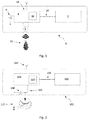
- Figure 1 shows a first smoke detector 1, for use in a fire alarm system.
- the smoke detector 1 comprises a smoke detector controller 2.
- the smoke detector controller 2 could be any microcontroller or processor suitable for controlling the smoke detector 1 during normal operation, i.e. after the smoke detector 1 has been initialised in the fire alarm system.
- the smoke detector controller 2 is configured to operate the smoke detector 1 during normal operation, for example, detecting an increase in smoke levels, determining that the smoke levels exceed a predetermined threshold value, and communicating to a fire alarm control panel via a network that the smoke levels have exceeded the threshold value.
- the smoke detector 1 also comprises a monitoring module 4.
- the monitoring module 4 comprises a RFID tag and an antenna 14 for receiving and transmitting wireless signals.
- the RFID tag is a semi-passive RFID tag and comprises a local source of power, such as an internal battery 6.
- the internal battery 6 provides the RFID tag with power so that it may function when the smoke detector 1 (and the smoke detector controller 2) is not being supplied with power through connection to a power source, such as the power source of the fire alarm system, e.g. a mains power source.
- the monitoring module 4 is configured to determine occurrence of a predetermined event 12 and to store an indication of the occurrence of the event.
- the monitoring module 4 is configured to determine if the smoke detector 1 has been exposed to a temperature above a predetermined temperature threshold. Exposure to high temperatures may internally damage the smoke detector 1 and modify its sensitivity, thus rendering it unsafe.
- the monitoring module 4 comprises a heat sensor 8.
- the heat sensor is powered by the internal battery 6.
- the heat sensor 8 is configured to detect an ambient temperature within the proximity of the smoke detector 1.
- the monitoring module 4 is configured to periodically interrogate the heat sensor 8 to determine whether the smoke detector 1 is being exposed to a temperature above a predetermined temperature threshold.
- the monitoring module 4 further comprises a memory 10. Responsive to determining that the smoke detector 1 has been exposed to a temperature exceeding the predetermined threshold, the monitoring module 4 will store a flag within the memory 10 as an indication of the occurrence of this event. Optionally, the monitoring module 4 may record additional information, such as a maximum temperature to which the smoke detector 1 was exposed.
- the monitoring module 4 comprises an RFID tag.
- the RFID tag allows an external RFID reader device to interrogate the monitoring module 4 to determine whether a flag has been stored in the memory 10 of the monitoring module 4 to indicate that the smoke detector 1 has been exposed to a temperature exceeding the predetermined temperature.
- the smoke detector controller 2 may be configured to internally communicate with the monitoring module 4 through a digital interface 16.
- the smoke detector controller 2 may be capable of interrogating the monitoring module 4 to determine whether a flag has been stored in the memory 10 of the monitoring module 4 to indicate that the smoke detector 1 has been exposed to a temperature exceeding the predetermined temperature.
- the smoke detector 1 When the smoke detector 1 is in a state where it is not being supplied with power (e.g. the smoke detector 1 is stored in a warehouse or is being transported), the smoke detector 1 may experience a predetermined event 12 such as exposure to a temperature above a predetermined threshold.
- a predetermined event 12 such as exposure to a temperature above a predetermined threshold.
- Exposure to a temperature above the predetermined threshold will trigger the heat sensor 8.
- the monitoring module 4 determines that the smoke detector 1 has been exposed to excessive temperature, and in response stores an indication of the occurrence of the event in the memory 10 of the monitoring module 4.
- the smoke detector 1 is therefore able to monitor the status of the smoke detector 1 during a period when it is not being supplied with power, and determine if the smoke detector 1 has been exposed to an excessive temperature that may have a negative impact on the normal mode of operation of the smoke detector 1.
- the monitoring module 4 can be interrogated in two ways.
- the monitoring module 4 may receive a RFID read request from a transceiver (interrogator) via the antenna 14 of the RFID tag. In response to the RFID read request, the monitoring module 4 is configured to transmit any stored indications to the transceiver. In this way a manufacturer can advantageously check, before delivery to an end user, if a smoke detector 1 has been exposed to an excessive temperature during a period of storage.
- the use of an RFID interrogator which does not require line-of-sight in order to interact with RFID tags like monitoring module 4, means that with a sufficiently powerful excitation field multiple smoke detectors 1 may be checked simultaneously, which can increase the speed and efficiency of the quality control procedure.
- a transceiver may be utilised by the end user to check if the smoke detector 1 has been exposed to excessive temperature prior to receipt by the end user.
- the smoke detector controller 2 upon commencing initialisation of the smoke detector 1 (e.g. when the smoke detector 1 is connected into an alarm system during installation and is supplied with power), the smoke detector controller 2 starts up and transmits a read request to the monitoring module 4 to see if an indication of the smoke detector 1 being exposed to excessive temperature has been stored. If such an indication is returned as a result of the read request, then the smoke detector controller 2 may notify a user (which may be a maintenance engineer, or the like, tasked with installing the smoke detector 1 in the fire alarm system) that the smoke detector 1 has been exposed to excessive temperature and may be internally damaged as a result. The smoke detector controller 2 notifies the user by activating a notification means (not shown) of the smoke detector 1, such as an LED or buzzer.
- a notification means not shown
- Figure 2 shows a second smoke detector 101 for use in a fire alarm system.
- the second smoke detector 101 operates in a similar manner to the first smoke detector 1 described above, but differs in the following aspects. Like elements are numbered with corresponding reference signs, but incremented by 100.
- the monitoring module 104 is configured to determine if the smoke detector 101 has been manipulated in a particular manner, and thus comprises a manipulation detection switch 108. Unauthorised manipulation of the smoke detector 101 may cause internal damage and the smoke detector 101 could become faulty and not suitable for installation in the fire alarm system.
- the manipulation switch 108 is an embedded mechanical switch, which in this embodiment connects the monitoring module 104 to the internal battery 106.
- the switch 108 connects the monitoring module 104 to the internal battery 106, which is normally disconnected from the monitoring module 104 in this embodiment. Therefore, upon supply of power from internal battery 106, the monitoring module 104 detects that the smoke detector 101 has been manipulated and the monitoring module 104 will store a flag within the memory 110 as an indication of the occurrence of this event.
- the smoke detector 101 When the smoke detector 101 is in a state where it is not being supplied with power (e.g. the smoke detector 101 is stored in a warehouse or is being transported), the smoke detector 101 may experience a predetermined event 112 such as unauthorised tampering with the smoke detector 101.
- a predetermined event 112 such as unauthorised tampering with the smoke detector 101.
- the unauthorised tampering particularly the removal of the housing of the smoke detector 101, will cause the switch 108 to connect the monitoring module 4 to the internal battery 106.
- the monitoring module 104 detects that power from the battery 106 has been supplied and therefore determines that the housing has been removed. In response, the monitoring module 104 stores an indication of the occurrence of manipulation in the memory 110 of the monitoring module 104.
- the monitoring module 104 may be interrogated by the smoke detector controller 102 or by an RFID interrogator.
- shock damage may be detected by a suitable shock sensor, for example including an accelerometer.
- the detection techniques used in either of the first and second smoke detectors 1, 101 may be used for detection of the other predetermined event.
- a mechanical switch could be provided for connecting the battery 6 to the monitoring module 4 when the temperature exceeds a predetermined temperature.
- an active sensor could be provided for detecting that the housing of the smoke detector 101 has been removed.
- a monitoring module 4 may comprise both a sensor 8 for detecting excessive temperature and a sensor 108 for detecting tampering. Then, the monitoring module 4 may store the indication of the occurrence of either predetermined event 12, 112. This advantageously allows the controller 2 or transceiver to quickly identify which particular predetermined event 12, 112 occurred, such that knowledge about the transport or storage conditions of the smoke detector 1 can be obtained.
Landscapes
- Engineering & Computer Science (AREA)
- Physics & Mathematics (AREA)
- General Physics & Mathematics (AREA)
- Theoretical Computer Science (AREA)
- Computer Vision & Pattern Recognition (AREA)
- Artificial Intelligence (AREA)
- General Engineering & Computer Science (AREA)
- Computer Networks & Wireless Communication (AREA)
- Computer Hardware Design (AREA)
- Microelectronics & Electronic Packaging (AREA)
- Computer Security & Cryptography (AREA)
- Fire Alarms (AREA)
- Alarm Systems (AREA)
Abstract
Description
- The present disclosure relates to a component for use in an alarm system, and particularly to a technique for detecting events when the component is unpowered.
- An alarm system, such as a fire alarm system or an intrusion alarm system, comprises a variety of components working in unison to detect and warn people in the event that a change in an environmental parameter has occurred.
- If any one of the components of the alarm system, upon installation in the alarm system, is faulty or has been damaged, this can seriously reduce the sensitivity and effectiveness of the alarm system, and thereby its safety.
- Testing each individual component or indeed the entire alarm system each time a new component is installed is very time consuming, and in some instances impractical.
- A need therefore exists for an improved alarm system component.
- Viewed from a first aspect, there is provided a component for use in an alarm system comprising: a component controller configured to control the component when power is supplied to the component; and a monitoring module comprising a power source and configured to monitor the component when power is not supplied to the component, wherein the monitoring module is configured to determine occurrence of a predetermined event and to store an indication of the occurrence of the event.
- The described component may advantageously determine if there has been an occurrence of a predetermined event and store an indication of the occurrence of the event despite power not being supplied to the component. The power source of the monitoring module provides the monitoring module with sufficient power to monitor the status of the component during this period and identify if the component has been manipulated or damaged. A user may check the status of the component and determine if the component is safe to use in an alarm system.
- The predetermined event may comprise exposure of the component to a temperature exceeding a predetermined threshold temperature.
- The predetermined event may comprise manipulation of the component in a predetermined manner.
- The monitoring module may comprise an RFID tag, which may be an active or semi-passive RFID tag. The power source may be an internal battery of the RFID tag. A semi-passive or active RFID tag may be configured to draw power from the internal battery for operation of sensors and the like. An active RFID may be further configured to draw power from the internal battery for RF communication over increased distances relative to a passive or semi-passive RFID tag.
- RFID readers do not require line-of-sight in order to interact with RFID tags which can increase speed and efficiency of an interrogation/request for information. For example, the use of RFID technology may allow for multiple monitoring modules to be interrogated at once.
- The monitoring module may comprise a memory, and the indication of the occurrence of the event may be stored in the memory. The monitoring module memory may be electrically erasable, programmable, read-only memory (EEPROM). The monitoring module memory may be read-write or write-once, read-multiple (WORM).
- The monitoring module may comprise at least one sensor, wherein the sensor is configured to determine the occurrence of a predetermined event.
- The at least one sensor may include at least one of a tamper detection sensor, a heat detection sensor, and a shock sensor.
- The tamper detection sensor may be a mechanical switch.
- The at least one sensor may be configured to be triggered in response to a predetermined threshold value of an environmental parameter being exceeded.
- The monitoring module may be configured to transmit the stored indication of the occurrence of an event in response to a read request.
- The component controller may be configured to issue the read request after power has been supplied to the component. The component controller may be configured to begin to initialise upon connection to a power source during installation of the component in an alarm system. Initialisation of the component controller may comprise the subsequent activation and start-up procedure of the component controller.
- The monitoring module may be configured to communicate with the component controller via a digital interface.
- The component controller may be configured to take an action in response to receiving the stored indication of the occurrence of the predetermined event from the monitoring module. The action may comprise triggering an alert. The action may comprise notifying a user of the occurrence of the event.
- The component may be configured to notify the user in response to the component controller receiving the stored indication of the occurrence of the predetermined event from the monitoring module. The component may comprise a notification means for generating the notification. The notification means may comprise an audible or visual alarm, such as a buzzer or an LED.
- The monitoring module may be configured to directly receive a read request from a wireless transceiver.
- The monitoring module may comprise a plurality of sensors. It is advantageous to have a sensor directed to each predetermined event that may possibly occur to the component while in storage or transit.
- The monitoring module may be configured to store the indication of the occurrence of an event in a dedicated field in the memory, wherein the dedicated field corresponds to the particular sensor triggered by the occurrence of a predetermined event. This advantageously allows the component controller to identify which particular predetermined event occurred by the location of the indication in the memory, such that knowledge about the transport or storage conditions of a component can be quickly obtained.
- The alarm system may be a fire alarm system.
- The component may be a fire detection component, such as a heat detector or a smoke detector.
- The component may be a fire alarm control panel, preferably an addressable fire alarm control panel. The component may be a fire suppression component such as a sprinkler system or fire door holder. The component may be a fire notification component, such as a visual or audible fire alarm, or voice evacuation system. The alarm system may be an intrusion alarm system. The component may be an infrared or motion sensor.
- Viewed from a second aspect, the present disclosure provides a method of monitoring a component for an alarm system, the method comprising: determining, by a monitoring module of the component, that a predetermined event has occurred whilst power is not being supplied to the component, wherein the monitoring module has a local source of power; and storing, by the monitoring module, an indication of the occurrence of the event.
- The component may be as discussed above in the first aspect and optionally may include any/all of the further features discussed above.
- The step of storing of an indication of the occurrence of the event may comprise storing the indication in a memory of the monitoring module.
- The step of determining that the predetermined event has occurred may comprise determining if at least one sensor has been triggered in response to a predetermined threshold value of an environmental parameter being exceeded.
- The step of storing of an indication of the occurrence of the predetermined event may comprise storing the indication in a dedicated field in the memory of the monitoring module, wherein the dedicated field corresponds to the particular sensor triggered by the occurrence of the event.
- The method of monitoring a component for an alarm system may further comprise transmitting the stored indication of the occurrence of the event in response to a read request.
- The step of transmitting the stored indication of the occurrence of the event in response to the read request may comprise: supplying power to the component; transmitting the read request, by the component controller, to the monitoring module; receiving, by the monitoring module, the read request; and transmitting, by the monitoring module, the stored indication of the occurrence of the event to the component controller in response to the read request.
- The method of monitoring a component for an alarm system may further comprise notifying, by the component, a user that the predetermined event has occurred in response to the component controller receiving the stored indication. Providing this safety feature of notifying a user that an event has occurred advantageously prevents the user from installing a potentially faulty component in an alarm system.
- The step of transmitting the stored indication of the occurrence of the event in response to the read request may comprise: receiving, by the monitoring module, wireless transmission of a read request; and transmitting, by the monitoring module, the stored indication of the occurrence of the event in response to the read request.
- Viewed from a third aspect, the present invention provides a computer-readable storage medium comprising instructions which, when executed by a monitoring module of a component for an alarm system, wherein the monitoring module has a local source of power, cause the monitoring module to carry out a method of monitoring the component, the method comprising: determining that a predetermined event has occurred whilst power is not being supplied to the component; and storing an indication of the occurrence of the event.
- The method may be as discussed above in relation to the second aspect and optional features thereof.
- An embodiment of the present disclosure will now be described in greater detail, by way of example only and with reference to the drawings, in which:
-
Figure 1 shows a schematic illustration of a first smoke detector for use in a fire alarm system; -
Figure 2 shows a schematic illustration of a second smoke detector for use in a fire alarm system. -
Figure 1 shows afirst smoke detector 1, for use in a fire alarm system. - The
smoke detector 1 comprises asmoke detector controller 2. Thesmoke detector controller 2 could be any microcontroller or processor suitable for controlling thesmoke detector 1 during normal operation, i.e. after thesmoke detector 1 has been initialised in the fire alarm system. - The
smoke detector controller 2 is configured to operate thesmoke detector 1 during normal operation, for example, detecting an increase in smoke levels, determining that the smoke levels exceed a predetermined threshold value, and communicating to a fire alarm control panel via a network that the smoke levels have exceeded the threshold value. - The
smoke detector 1 also comprises amonitoring module 4. Themonitoring module 4 comprises a RFID tag and anantenna 14 for receiving and transmitting wireless signals. - The RFID tag is a semi-passive RFID tag and comprises a local source of power, such as an
internal battery 6. Theinternal battery 6 provides the RFID tag with power so that it may function when the smoke detector 1 (and the smoke detector controller 2) is not being supplied with power through connection to a power source, such as the power source of the fire alarm system, e.g. a mains power source. - The
monitoring module 4 is configured to determine occurrence of apredetermined event 12 and to store an indication of the occurrence of the event. - In this embodiment, the
monitoring module 4 is configured to determine if thesmoke detector 1 has been exposed to a temperature above a predetermined temperature threshold. Exposure to high temperatures may internally damage thesmoke detector 1 and modify its sensitivity, thus rendering it unsafe. - The
monitoring module 4 comprises aheat sensor 8. The heat sensor is powered by theinternal battery 6. Theheat sensor 8 is configured to detect an ambient temperature within the proximity of thesmoke detector 1. Themonitoring module 4 is configured to periodically interrogate theheat sensor 8 to determine whether thesmoke detector 1 is being exposed to a temperature above a predetermined temperature threshold. - The
monitoring module 4 further comprises amemory 10. Responsive to determining that thesmoke detector 1 has been exposed to a temperature exceeding the predetermined threshold, themonitoring module 4 will store a flag within thememory 10 as an indication of the occurrence of this event. Optionally, themonitoring module 4 may record additional information, such as a maximum temperature to which thesmoke detector 1 was exposed. - As discussed above, the
monitoring module 4 comprises an RFID tag. The RFID tag allows an external RFID reader device to interrogate themonitoring module 4 to determine whether a flag has been stored in thememory 10 of themonitoring module 4 to indicate that thesmoke detector 1 has been exposed to a temperature exceeding the predetermined temperature. - Additionally, or alternatively, the
smoke detector controller 2 may be configured to internally communicate with themonitoring module 4 through adigital interface 16. For example, thesmoke detector controller 2 may be capable of interrogating themonitoring module 4 to determine whether a flag has been stored in thememory 10 of themonitoring module 4 to indicate that thesmoke detector 1 has been exposed to a temperature exceeding the predetermined temperature. - A method of monitoring the
smoke detector 1, while thesmoke detector 1 is not being supplied with power, is now described. - When the
smoke detector 1 is in a state where it is not being supplied with power (e.g. thesmoke detector 1 is stored in a warehouse or is being transported), thesmoke detector 1 may experience apredetermined event 12 such as exposure to a temperature above a predetermined threshold. - Exposure to a temperature above the predetermined threshold will trigger the
heat sensor 8. Themonitoring module 4 determines that thesmoke detector 1 has been exposed to excessive temperature, and in response stores an indication of the occurrence of the event in thememory 10 of themonitoring module 4. - The
smoke detector 1 is therefore able to monitor the status of thesmoke detector 1 during a period when it is not being supplied with power, and determine if thesmoke detector 1 has been exposed to an excessive temperature that may have a negative impact on the normal mode of operation of thesmoke detector 1. - In the illustrated embodiments, the
monitoring module 4 can be interrogated in two ways. - In a first instance, the
monitoring module 4 may receive a RFID read request from a transceiver (interrogator) via theantenna 14 of the RFID tag. In response to the RFID read request, themonitoring module 4 is configured to transmit any stored indications to the transceiver. In this way a manufacturer can advantageously check, before delivery to an end user, if asmoke detector 1 has been exposed to an excessive temperature during a period of storage. The use of an RFID interrogator, which does not require line-of-sight in order to interact with RFID tags likemonitoring module 4, means that with a sufficiently powerful excitation fieldmultiple smoke detectors 1 may be checked simultaneously, which can increase the speed and efficiency of the quality control procedure. Similarly, a transceiver may be utilised by the end user to check if thesmoke detector 1 has been exposed to excessive temperature prior to receipt by the end user. - In a second instance, upon commencing initialisation of the smoke detector 1 (e.g. when the
smoke detector 1 is connected into an alarm system during installation and is supplied with power), thesmoke detector controller 2 starts up and transmits a read request to themonitoring module 4 to see if an indication of thesmoke detector 1 being exposed to excessive temperature has been stored. If such an indication is returned as a result of the read request, then thesmoke detector controller 2 may notify a user (which may be a maintenance engineer, or the like, tasked with installing thesmoke detector 1 in the fire alarm system) that thesmoke detector 1 has been exposed to excessive temperature and may be internally damaged as a result. Thesmoke detector controller 2 notifies the user by activating a notification means (not shown) of thesmoke detector 1, such as an LED or buzzer. -
Figure 2 shows asecond smoke detector 101 for use in a fire alarm system. - The
second smoke detector 101 operates in a similar manner to thefirst smoke detector 1 described above, but differs in the following aspects. Like elements are numbered with corresponding reference signs, but incremented by 100. - In this embodiment, the
monitoring module 104 is configured to determine if thesmoke detector 101 has been manipulated in a particular manner, and thus comprises amanipulation detection switch 108. Unauthorised manipulation of thesmoke detector 101 may cause internal damage and thesmoke detector 101 could become faulty and not suitable for installation in the fire alarm system. - The
manipulation switch 108 is an embedded mechanical switch, which in this embodiment connects themonitoring module 104 to theinternal battery 106. When thesmoke detector 101 is manipulated in a particular manner, such as when the housing of thesmoke detector 101 is removed, theswitch 108 connects themonitoring module 104 to theinternal battery 106, which is normally disconnected from themonitoring module 104 in this embodiment. Therefore, upon supply of power frominternal battery 106, themonitoring module 104 detects that thesmoke detector 101 has been manipulated and themonitoring module 104 will store a flag within thememory 110 as an indication of the occurrence of this event. - A method of monitoring the
second smoke detector 101, while thesmoke detector 101 is not being supplied with power, is now described. - When the
smoke detector 101 is in a state where it is not being supplied with power (e.g. thesmoke detector 101 is stored in a warehouse or is being transported), thesmoke detector 101 may experience apredetermined event 112 such as unauthorised tampering with thesmoke detector 101. - The unauthorised tampering, particularly the removal of the housing of the
smoke detector 101, will cause theswitch 108 to connect themonitoring module 4 to theinternal battery 106. Themonitoring module 104 detects that power from thebattery 106 has been supplied and therefore determines that the housing has been removed. In response, themonitoring module 104 stores an indication of the occurrence of manipulation in thememory 110 of themonitoring module 104. - As above, the
monitoring module 104 may be interrogated by thesmoke detector controller 102 or by an RFID interrogator. - Whilst two exemplary events are illustrated above, being exposed to excessive temperature or manipulation of the housing, it will be appreciate that other types of events may be detected by similar techniques. For example, shock damage may be detected by a suitable shock sensor, for example including an accelerometer.
- Furthermore, the detection techniques used in either of the first and
second smoke detectors battery 6 to themonitoring module 4 when the temperature exceeds a predetermined temperature. Likewise, an active sensor could be provided for detecting that the housing of thesmoke detector 101 has been removed. - In a further alternative embodiment a
monitoring module 4 may comprise both asensor 8 for detecting excessive temperature and asensor 108 for detecting tampering. Then, themonitoring module 4 may store the indication of the occurrence of eitherpredetermined event controller 2 or transceiver to quickly identify which particularpredetermined event smoke detector 1 can be obtained. - Whilst the technique above has been described within the context of a smoke detector, it may be similarly employed in other components used within an alarm system.
Claims (15)
- A component for use in an alarm system comprising:a component controller configured to control the component when power is supplied to the component; anda monitoring module comprising a power source and configured to monitor the component when power is not supplied to the component,wherein the monitoring module is configured to determine occurrence of a predetermined event and to store an indication of the occurrence of the event.
- A component according to claim 1, wherein the predetermined event comprises exposure of the component to a temperature exceeding a predetermined threshold temperature.
- A component according to claim 1 or 2, wherein the predetermined event comprises manipulation of the component in a predetermined manner.
- A component according to any preceding claim, wherein the monitoring module comprises an RFID tag.
- A component according to any preceding claim, wherein the monitoring module is configured to transmit the stored indication of the occurrence of the predetermined event in response to a read request.
- A component according to claim 5, wherein the component controller is configured to issue the read request after power has been supplied to the component, and preferably wherein the component is configured to notify a user in response to the component controller receiving the stored indication of the occurrence of the predetermined event from the monitoring module.
- A component according to claim 5 or 6, wherein the monitoring module is configured to directly receive a read request from a wireless transceiver.
- A component according to any preceding claim, wherein the alarm system is a fire alarm system.
- A method of monitoring a component for an alarm system, the method comprising:determining, by a monitoring module of the component, that a predetermined event has occurred whilst power is not being supplied to the component, wherein the monitoring module has a local source of power; andstoring, by the monitoring module, an indication of the occurrence of the event.
- A method according to claim 9, wherein the monitoring module comprises an RFID tag.
- A method according to claim 9 or 10, wherein the step of determining that the predetermined event has occurred comprises:
determining if at least one sensor has been triggered in response to a predetermined threshold value of an environmental parameter being exceeded. - A method according to claim 9, 10 or 11, further comprising:
transmitting the stored indication of the occurrence of the event in response to a read request. - A method according to claim 12, wherein the step of transmitting the stored indication of the occurrence of the event in response to the read request comprises:supplying power to the component;transmitting the read request, by the component controller to the monitoring module;receiving, by the monitoring module, the read request; andtransmitting, by the monitoring module, the stored indication of the occurrence of the event to the component controller in response to the read request.
- A method according to claim 13, further comprising:
notifying, by the component, a user that the predetermined event has occurred in response to the component controller receiving the stored indication. - A method according to claim 12, wherein the step of transmitting the stored indication of the occurrence of the event in response to the read request comprises:receiving, by the monitoring module, wireless transmission of a read request; andtransmitting, by the monitoring module, the stored indication of the occurrence of the event in response to the read request.
Priority Applications (4)
| Application Number | Priority Date | Filing Date | Title |
|---|---|---|---|
| ES20382382T ES2972038T3 (en) | 2020-05-08 | 2020-05-08 | Alarm system component with non-powered event detection |
| EP20382382.8A EP3907717B1 (en) | 2020-05-08 | 2020-05-08 | Alarm system component with event detection while being unpowered |
| US17/116,500 US20210350195A1 (en) | 2020-05-08 | 2020-12-09 | Alarm system component with unpowered event detection |
| US18/446,836 US12229611B2 (en) | 2020-05-08 | 2023-08-09 | Alarm system component with unpowered event detection |
Applications Claiming Priority (1)
| Application Number | Priority Date | Filing Date | Title |
|---|---|---|---|
| EP20382382.8A EP3907717B1 (en) | 2020-05-08 | 2020-05-08 | Alarm system component with event detection while being unpowered |
Publications (2)
| Publication Number | Publication Date |
|---|---|
| EP3907717A1 true EP3907717A1 (en) | 2021-11-10 |
| EP3907717B1 EP3907717B1 (en) | 2024-02-14 |
Family
ID=70779645
Family Applications (1)
| Application Number | Title | Priority Date | Filing Date |
|---|---|---|---|
| EP20382382.8A Active EP3907717B1 (en) | 2020-05-08 | 2020-05-08 | Alarm system component with event detection while being unpowered |
Country Status (3)
| Country | Link |
|---|---|
| US (2) | US20210350195A1 (en) |
| EP (1) | EP3907717B1 (en) |
| ES (1) | ES2972038T3 (en) |
Families Citing this family (1)
| Publication number | Priority date | Publication date | Assignee | Title |
|---|---|---|---|---|
| EP3907717B1 (en) | 2020-05-08 | 2024-02-14 | Carrier Corporation | Alarm system component with event detection while being unpowered |
Citations (3)
| Publication number | Priority date | Publication date | Assignee | Title |
|---|---|---|---|---|
| US20080048857A1 (en) * | 2006-06-08 | 2008-02-28 | Patent Navigation Inc. | RFID affected by sensor event |
| US20120114010A1 (en) * | 2010-11-09 | 2012-05-10 | Shockwatch, Inc. | System, method and computer program product for monitoring temperature |
| CN204389068U (en) * | 2015-02-02 | 2015-06-10 | 武汉辉达工控技术有限公司 | A kind of sensor ageing monitoring system |
Family Cites Families (26)
| Publication number | Priority date | Publication date | Assignee | Title |
|---|---|---|---|---|
| US5339072A (en) | 1991-12-09 | 1994-08-16 | Nohmi Bosai, Ltd | Fire detector with anti-tampering measures for use in vehicles |
| US5473322A (en) | 1992-07-24 | 1995-12-05 | Schlumberger Industries, Inc. | Apparatus and method for sensing tampering with a utility meter |
| US6232886B1 (en) | 1998-12-23 | 2001-05-15 | Schlumberger Resource Management Services, Inc. | Method and apparatus for indicating meter tampering |
| US20020045992A1 (en) | 2000-09-25 | 2002-04-18 | Shincovich John T. | Point of use digital electric energy apparatus and method for measuring out-of-specification energy |
| US6943691B2 (en) | 2001-01-19 | 2005-09-13 | Bill Chambers | Tamper indicator for a smoke detector |
| WO2003049528A2 (en) | 2001-12-07 | 2003-06-19 | Michael Zoratti | Fire hydrant anti-tamper device |
| US7042349B2 (en) * | 2002-08-30 | 2006-05-09 | General Electric Company | Testing and installing sensors in a security system |
| US20040129312A1 (en) | 2003-01-03 | 2004-07-08 | Joseph Cuzzo | Water system tampering sensing device |
| US6940410B2 (en) | 2003-10-16 | 2005-09-06 | Dan Deacy | Tobacco smoke detection system with tamper detection |
| US20050128093A1 (en) | 2003-12-16 | 2005-06-16 | Genova James J. | Self-protected fire-sensing alarm apparatus and method |
| US7004784B2 (en) | 2004-02-26 | 2006-02-28 | Robert Bosch Gmbh | Tamper detection for security system |
| US7348875B2 (en) | 2004-05-04 | 2008-03-25 | Battelle Memorial Institute | Semi-passive radio frequency identification (RFID) tag with active beacon |
| US7274289B2 (en) | 2004-05-27 | 2007-09-25 | Eastman Kodak Company | System and device for detecting object tampering |
| US7746222B2 (en) * | 2006-10-23 | 2010-06-29 | Robert Bosch Gmbh | Method and apparatus for installing a wireless security system |
| US7847690B2 (en) | 2007-12-26 | 2010-12-07 | Elster Electricity Llc | System and method for detecting tampering of a utility meter |
| US20100231407A1 (en) | 2009-03-13 | 2010-09-16 | New Jersey Microsystems, Inc. | RFID power control and monitoring system |
| US9082057B2 (en) | 2009-08-19 | 2015-07-14 | Intelleflex Corporation | RF device with tamper detection |
| GB2484458A (en) * | 2010-10-04 | 2012-04-18 | Thorn Security | Commissioning detector units of an alarm system by means of a remote infrared based communication tool |
| EP2686839A4 (en) * | 2011-03-17 | 2014-10-01 | Assa Abloy Ab | Method for upgrading rfid readers in situ |
| US10352782B2 (en) * | 2017-03-06 | 2019-07-16 | Nxp Usa, Inc. | Thermal monitoring system in an integrated circuit die |
| US10337715B2 (en) * | 2017-04-24 | 2019-07-02 | HKC Corporation Limited | Lighting box and monitoring method therefor |
| US10359771B2 (en) * | 2017-06-08 | 2019-07-23 | Tyco Fire & Security Gmbh | Prediction of false alarms in sensor-based security systems |
| US10408684B2 (en) * | 2017-11-10 | 2019-09-10 | Seagate Technolgy Llc | Integrated thermal management of storage drives |
| US11651675B2 (en) * | 2018-02-02 | 2023-05-16 | Siemens Schweiz Ag | Safety device inspection |
| EP3907711A1 (en) * | 2020-05-08 | 2021-11-10 | Carrier Corporation | Configurable alarm system component |
| EP3907717B1 (en) | 2020-05-08 | 2024-02-14 | Carrier Corporation | Alarm system component with event detection while being unpowered |
-
2020
- 2020-05-08 EP EP20382382.8A patent/EP3907717B1/en active Active
- 2020-05-08 ES ES20382382T patent/ES2972038T3/en active Active
- 2020-12-09 US US17/116,500 patent/US20210350195A1/en not_active Abandoned
-
2023
- 2023-08-09 US US18/446,836 patent/US12229611B2/en active Active
Patent Citations (3)
| Publication number | Priority date | Publication date | Assignee | Title |
|---|---|---|---|---|
| US20080048857A1 (en) * | 2006-06-08 | 2008-02-28 | Patent Navigation Inc. | RFID affected by sensor event |
| US20120114010A1 (en) * | 2010-11-09 | 2012-05-10 | Shockwatch, Inc. | System, method and computer program product for monitoring temperature |
| CN204389068U (en) * | 2015-02-02 | 2015-06-10 | 武汉辉达工控技术有限公司 | A kind of sensor ageing monitoring system |
Also Published As
| Publication number | Publication date |
|---|---|
| EP3907717B1 (en) | 2024-02-14 |
| ES2972038T3 (en) | 2024-06-10 |
| US20210350195A1 (en) | 2021-11-11 |
| US12229611B2 (en) | 2025-02-18 |
| US20230385588A1 (en) | 2023-11-30 |
Similar Documents
| Publication | Publication Date | Title |
|---|---|---|
| KR101782437B1 (en) | Eas alarming tag with rfid features | |
| US7859404B2 (en) | Method and apparatus for proximity activated RFID system | |
| US7081815B2 (en) | Radio frequency security system, method for a building facility or the like, and apparatus and methods for remotely monitoring the status of fire extinguishers | |
| CN101460981B (en) | Security device for monitoring integrity of closed objects | |
| EA010438B1 (en) | Wireless monitoring device | |
| EP1468409B1 (en) | Method and apparatus for monitoring fire detectors | |
| EP1749285B1 (en) | System and device for detecting object tampering | |
| US7652575B2 (en) | Monitoring of packages | |
| US20100289647A1 (en) | Detection of Changes in Fasteners or Fastened Joints | |
| CN101065787A (en) | Mems sensor unit for security applications | |
| US11016189B2 (en) | Systems and methods for security system device tamper detection | |
| US12229611B2 (en) | Alarm system component with unpowered event detection | |
| US8736444B2 (en) | System and method for wireless heat detection | |
| US20040212479A1 (en) | Method and system for remote monitoring and control utilizing radio frequency devices | |
| CN105761415A (en) | Fire alarm smoke alarming device with positioning function | |
| US9589223B2 (en) | Modular radio-identification system with passive RFID module and active RFID module | |
| KR20090001767A (en) | Military and neck weapons tracking system and control method | |
| JP2005210248A (en) | Detection system and charging method therefor | |
| KR101102030B1 (en) | Material theft prevention system and method | |
| CN111310877B (en) | Asset monitoring method, equipment and storage medium | |
| KR101663776B1 (en) | Storage saving CCTV system using RFID and it's control method | |
| US11651187B2 (en) | Reusable seal and vehicle comprising a reusable seal | |
| KR102052622B1 (en) | Locking device and system for storage of computer | |
| CN104966365A (en) | Transformer anti-theft monitoring system | |
| KR20140095350A (en) | Apparatus and mehtod for protecting intrusion |
Legal Events
| Date | Code | Title | Description |
|---|---|---|---|
| PUAI | Public reference made under article 153(3) epc to a published international application that has entered the european phase |
Free format text: ORIGINAL CODE: 0009012 |
|
| STAA | Information on the status of an ep patent application or granted ep patent |
Free format text: STATUS: THE APPLICATION HAS BEEN PUBLISHED |
|
| AK | Designated contracting states |
Kind code of ref document: A1 Designated state(s): AL AT BE BG CH CY CZ DE DK EE ES FI FR GB GR HR HU IE IS IT LI LT LU LV MC MK MT NL NO PL PT RO RS SE SI SK SM TR |
|
| B565 | Issuance of search results under rule 164(2) epc |
Effective date: 20201110 |
|
| STAA | Information on the status of an ep patent application or granted ep patent |
Free format text: STATUS: REQUEST FOR EXAMINATION WAS MADE |
|
| 17P | Request for examination filed |
Effective date: 20220505 |
|
| RBV | Designated contracting states (corrected) |
Designated state(s): AL AT BE BG CH CY CZ DE DK EE ES FI FR GB GR HR HU IE IS IT LI LT LU LV MC MK MT NL NO PL PT RO RS SE SI SK SM TR |
|
| GRAP | Despatch of communication of intention to grant a patent |
Free format text: ORIGINAL CODE: EPIDOSNIGR1 |
|
| STAA | Information on the status of an ep patent application or granted ep patent |
Free format text: STATUS: GRANT OF PATENT IS INTENDED |
|
| INTG | Intention to grant announced |
Effective date: 20231009 |
|
| GRAS | Grant fee paid |
Free format text: ORIGINAL CODE: EPIDOSNIGR3 |
|
| GRAA | (expected) grant |
Free format text: ORIGINAL CODE: 0009210 |
|
| STAA | Information on the status of an ep patent application or granted ep patent |
Free format text: STATUS: THE PATENT HAS BEEN GRANTED |
|
| AK | Designated contracting states |
Kind code of ref document: B1 Designated state(s): AL AT BE BG CH CY CZ DE DK EE ES FI FR GB GR HR HU IE IS IT LI LT LU LV MC MK MT NL NO PL PT RO RS SE SI SK SM TR |
|
| REG | Reference to a national code |
Ref country code: GB Ref legal event code: FG4D |
|
| REG | Reference to a national code |
Ref country code: CH Ref legal event code: EP |
|
| REG | Reference to a national code |
Ref country code: DE Ref legal event code: R096 Ref document number: 602020025619 Country of ref document: DE |
|
| REG | Reference to a national code |
Ref country code: IE Ref legal event code: FG4D |
|
| REG | Reference to a national code |
Ref country code: LT Ref legal event code: MG9D Ref country code: ES Ref legal event code: FG2A Ref document number: 2972038 Country of ref document: ES Kind code of ref document: T3 Effective date: 20240610 |
|
| REG | Reference to a national code |
Ref country code: NL Ref legal event code: MP Effective date: 20240214 |
|
| PG25 | Lapsed in a contracting state [announced via postgrant information from national office to epo] |
Ref country code: IS Free format text: LAPSE BECAUSE OF FAILURE TO SUBMIT A TRANSLATION OF THE DESCRIPTION OR TO PAY THE FEE WITHIN THE PRESCRIBED TIME-LIMIT Effective date: 20240614 |
|
| PG25 | Lapsed in a contracting state [announced via postgrant information from national office to epo] |
Ref country code: LT Free format text: LAPSE BECAUSE OF FAILURE TO SUBMIT A TRANSLATION OF THE DESCRIPTION OR TO PAY THE FEE WITHIN THE PRESCRIBED TIME-LIMIT Effective date: 20240214 |
|
| PG25 | Lapsed in a contracting state [announced via postgrant information from national office to epo] |
Ref country code: GR Free format text: LAPSE BECAUSE OF FAILURE TO SUBMIT A TRANSLATION OF THE DESCRIPTION OR TO PAY THE FEE WITHIN THE PRESCRIBED TIME-LIMIT Effective date: 20240515 |
|
| REG | Reference to a national code |
Ref country code: AT Ref legal event code: MK05 Ref document number: 1657724 Country of ref document: AT Kind code of ref document: T Effective date: 20240214 |
|
| PG25 | Lapsed in a contracting state [announced via postgrant information from national office to epo] |
Ref country code: HR Free format text: LAPSE BECAUSE OF FAILURE TO SUBMIT A TRANSLATION OF THE DESCRIPTION OR TO PAY THE FEE WITHIN THE PRESCRIBED TIME-LIMIT Effective date: 20240214 Ref country code: RS Free format text: LAPSE BECAUSE OF FAILURE TO SUBMIT A TRANSLATION OF THE DESCRIPTION OR TO PAY THE FEE WITHIN THE PRESCRIBED TIME-LIMIT Effective date: 20240514 Ref country code: NL Free format text: LAPSE BECAUSE OF FAILURE TO SUBMIT A TRANSLATION OF THE DESCRIPTION OR TO PAY THE FEE WITHIN THE PRESCRIBED TIME-LIMIT Effective date: 20240214 |
|
| PG25 | Lapsed in a contracting state [announced via postgrant information from national office to epo] |
Ref country code: AT Free format text: LAPSE BECAUSE OF FAILURE TO SUBMIT A TRANSLATION OF THE DESCRIPTION OR TO PAY THE FEE WITHIN THE PRESCRIBED TIME-LIMIT Effective date: 20240214 |
|
| PG25 | Lapsed in a contracting state [announced via postgrant information from national office to epo] |
Ref country code: RS Free format text: LAPSE BECAUSE OF FAILURE TO SUBMIT A TRANSLATION OF THE DESCRIPTION OR TO PAY THE FEE WITHIN THE PRESCRIBED TIME-LIMIT Effective date: 20240514 Ref country code: NL Free format text: LAPSE BECAUSE OF FAILURE TO SUBMIT A TRANSLATION OF THE DESCRIPTION OR TO PAY THE FEE WITHIN THE PRESCRIBED TIME-LIMIT Effective date: 20240214 Ref country code: LT Free format text: LAPSE BECAUSE OF FAILURE TO SUBMIT A TRANSLATION OF THE DESCRIPTION OR TO PAY THE FEE WITHIN THE PRESCRIBED TIME-LIMIT Effective date: 20240214 Ref country code: IS Free format text: LAPSE BECAUSE OF FAILURE TO SUBMIT A TRANSLATION OF THE DESCRIPTION OR TO PAY THE FEE WITHIN THE PRESCRIBED TIME-LIMIT Effective date: 20240614 Ref country code: HR Free format text: LAPSE BECAUSE OF FAILURE TO SUBMIT A TRANSLATION OF THE DESCRIPTION OR TO PAY THE FEE WITHIN THE PRESCRIBED TIME-LIMIT Effective date: 20240214 Ref country code: GR Free format text: LAPSE BECAUSE OF FAILURE TO SUBMIT A TRANSLATION OF THE DESCRIPTION OR TO PAY THE FEE WITHIN THE PRESCRIBED TIME-LIMIT Effective date: 20240515 Ref country code: FI Free format text: LAPSE BECAUSE OF FAILURE TO SUBMIT A TRANSLATION OF THE DESCRIPTION OR TO PAY THE FEE WITHIN THE PRESCRIBED TIME-LIMIT Effective date: 20240214 Ref country code: BG Free format text: LAPSE BECAUSE OF FAILURE TO SUBMIT A TRANSLATION OF THE DESCRIPTION OR TO PAY THE FEE WITHIN THE PRESCRIBED TIME-LIMIT Effective date: 20240214 Ref country code: AT Free format text: LAPSE BECAUSE OF FAILURE TO SUBMIT A TRANSLATION OF THE DESCRIPTION OR TO PAY THE FEE WITHIN THE PRESCRIBED TIME-LIMIT Effective date: 20240214 |
|
| PG25 | Lapsed in a contracting state [announced via postgrant information from national office to epo] |
Ref country code: PL Free format text: LAPSE BECAUSE OF FAILURE TO SUBMIT A TRANSLATION OF THE DESCRIPTION OR TO PAY THE FEE WITHIN THE PRESCRIBED TIME-LIMIT Effective date: 20240214 Ref country code: PT Free format text: LAPSE BECAUSE OF FAILURE TO SUBMIT A TRANSLATION OF THE DESCRIPTION OR TO PAY THE FEE WITHIN THE PRESCRIBED TIME-LIMIT Effective date: 20240614 |
|
| PG25 | Lapsed in a contracting state [announced via postgrant information from national office to epo] |
Ref country code: SE Free format text: LAPSE BECAUSE OF FAILURE TO SUBMIT A TRANSLATION OF THE DESCRIPTION OR TO PAY THE FEE WITHIN THE PRESCRIBED TIME-LIMIT Effective date: 20240214 Ref country code: PT Free format text: LAPSE BECAUSE OF FAILURE TO SUBMIT A TRANSLATION OF THE DESCRIPTION OR TO PAY THE FEE WITHIN THE PRESCRIBED TIME-LIMIT Effective date: 20240614 Ref country code: PL Free format text: LAPSE BECAUSE OF FAILURE TO SUBMIT A TRANSLATION OF THE DESCRIPTION OR TO PAY THE FEE WITHIN THE PRESCRIBED TIME-LIMIT Effective date: 20240214 Ref country code: LV Free format text: LAPSE BECAUSE OF FAILURE TO SUBMIT A TRANSLATION OF THE DESCRIPTION OR TO PAY THE FEE WITHIN THE PRESCRIBED TIME-LIMIT Effective date: 20240214 |
|
| PG25 | Lapsed in a contracting state [announced via postgrant information from national office to epo] |
Ref country code: DK Free format text: LAPSE BECAUSE OF FAILURE TO SUBMIT A TRANSLATION OF THE DESCRIPTION OR TO PAY THE FEE WITHIN THE PRESCRIBED TIME-LIMIT Effective date: 20240214 |
|
| PG25 | Lapsed in a contracting state [announced via postgrant information from national office to epo] |
Ref country code: SM Free format text: LAPSE BECAUSE OF FAILURE TO SUBMIT A TRANSLATION OF THE DESCRIPTION OR TO PAY THE FEE WITHIN THE PRESCRIBED TIME-LIMIT Effective date: 20240214 |
|
| PG25 | Lapsed in a contracting state [announced via postgrant information from national office to epo] |
Ref country code: EE Free format text: LAPSE BECAUSE OF FAILURE TO SUBMIT A TRANSLATION OF THE DESCRIPTION OR TO PAY THE FEE WITHIN THE PRESCRIBED TIME-LIMIT Effective date: 20240214 Ref country code: CZ Free format text: LAPSE BECAUSE OF FAILURE TO SUBMIT A TRANSLATION OF THE DESCRIPTION OR TO PAY THE FEE WITHIN THE PRESCRIBED TIME-LIMIT Effective date: 20240214 |
|
| PG25 | Lapsed in a contracting state [announced via postgrant information from national office to epo] |
Ref country code: SK Free format text: LAPSE BECAUSE OF FAILURE TO SUBMIT A TRANSLATION OF THE DESCRIPTION OR TO PAY THE FEE WITHIN THE PRESCRIBED TIME-LIMIT Effective date: 20240214 |
|
| PG25 | Lapsed in a contracting state [announced via postgrant information from national office to epo] |
Ref country code: SM Free format text: LAPSE BECAUSE OF FAILURE TO SUBMIT A TRANSLATION OF THE DESCRIPTION OR TO PAY THE FEE WITHIN THE PRESCRIBED TIME-LIMIT Effective date: 20240214 Ref country code: SK Free format text: LAPSE BECAUSE OF FAILURE TO SUBMIT A TRANSLATION OF THE DESCRIPTION OR TO PAY THE FEE WITHIN THE PRESCRIBED TIME-LIMIT Effective date: 20240214 Ref country code: RO Free format text: LAPSE BECAUSE OF FAILURE TO SUBMIT A TRANSLATION OF THE DESCRIPTION OR TO PAY THE FEE WITHIN THE PRESCRIBED TIME-LIMIT Effective date: 20240214 Ref country code: EE Free format text: LAPSE BECAUSE OF FAILURE TO SUBMIT A TRANSLATION OF THE DESCRIPTION OR TO PAY THE FEE WITHIN THE PRESCRIBED TIME-LIMIT Effective date: 20240214 Ref country code: DK Free format text: LAPSE BECAUSE OF FAILURE TO SUBMIT A TRANSLATION OF THE DESCRIPTION OR TO PAY THE FEE WITHIN THE PRESCRIBED TIME-LIMIT Effective date: 20240214 Ref country code: CZ Free format text: LAPSE BECAUSE OF FAILURE TO SUBMIT A TRANSLATION OF THE DESCRIPTION OR TO PAY THE FEE WITHIN THE PRESCRIBED TIME-LIMIT Effective date: 20240214 |
|
| REG | Reference to a national code |
Ref country code: DE Ref legal event code: R097 Ref document number: 602020025619 Country of ref document: DE |
|
| REG | Reference to a national code |
Ref country code: DE Ref legal event code: R119 Ref document number: 602020025619 Country of ref document: DE |
|
| PG25 | Lapsed in a contracting state [announced via postgrant information from national office to epo] |
Ref country code: IT Free format text: LAPSE BECAUSE OF FAILURE TO SUBMIT A TRANSLATION OF THE DESCRIPTION OR TO PAY THE FEE WITHIN THE PRESCRIBED TIME-LIMIT Effective date: 20240214 |
|
| PLBE | No opposition filed within time limit |
Free format text: ORIGINAL CODE: 0009261 |
|
| STAA | Information on the status of an ep patent application or granted ep patent |
Free format text: STATUS: NO OPPOSITION FILED WITHIN TIME LIMIT |
|
| REG | Reference to a national code |
Ref country code: CH Ref legal event code: PL |
|
| PG25 | Lapsed in a contracting state [announced via postgrant information from national office to epo] |
Ref country code: IT Free format text: LAPSE BECAUSE OF FAILURE TO SUBMIT A TRANSLATION OF THE DESCRIPTION OR TO PAY THE FEE WITHIN THE PRESCRIBED TIME-LIMIT Effective date: 20240214 |
|
| PG25 | Lapsed in a contracting state [announced via postgrant information from national office to epo] |
Ref country code: MC Free format text: LAPSE BECAUSE OF FAILURE TO SUBMIT A TRANSLATION OF THE DESCRIPTION OR TO PAY THE FEE WITHIN THE PRESCRIBED TIME-LIMIT Effective date: 20240214 |
|
| PG25 | Lapsed in a contracting state [announced via postgrant information from national office to epo] |
Ref country code: LU Free format text: LAPSE BECAUSE OF NON-PAYMENT OF DUE FEES Effective date: 20240508 |
|
| 26N | No opposition filed |
Effective date: 20241115 |
|
| PG25 | Lapsed in a contracting state [announced via postgrant information from national office to epo] |
Ref country code: MC Free format text: LAPSE BECAUSE OF FAILURE TO SUBMIT A TRANSLATION OF THE DESCRIPTION OR TO PAY THE FEE WITHIN THE PRESCRIBED TIME-LIMIT Effective date: 20240214 Ref country code: LU Free format text: LAPSE BECAUSE OF NON-PAYMENT OF DUE FEES Effective date: 20240508 Ref country code: CH Free format text: LAPSE BECAUSE OF NON-PAYMENT OF DUE FEES Effective date: 20240531 |
|
| REG | Reference to a national code |
Ref country code: BE Ref legal event code: MM Effective date: 20240531 |
|
| PG25 | Lapsed in a contracting state [announced via postgrant information from national office to epo] |
Ref country code: DE Free format text: LAPSE BECAUSE OF NON-PAYMENT OF DUE FEES Effective date: 20241203 |
|
| PG25 | Lapsed in a contracting state [announced via postgrant information from national office to epo] |
Ref country code: IE Free format text: LAPSE BECAUSE OF NON-PAYMENT OF DUE FEES Effective date: 20240508 |
|
| PG25 | Lapsed in a contracting state [announced via postgrant information from national office to epo] |
Ref country code: SI Free format text: LAPSE BECAUSE OF FAILURE TO SUBMIT A TRANSLATION OF THE DESCRIPTION OR TO PAY THE FEE WITHIN THE PRESCRIBED TIME-LIMIT Effective date: 20240214 Ref country code: BE Free format text: LAPSE BECAUSE OF NON-PAYMENT OF DUE FEES Effective date: 20240531 |
|
| PGFP | Annual fee paid to national office [announced via postgrant information from national office to epo] |
Ref country code: GB Payment date: 20250423 Year of fee payment: 6 Ref country code: ES Payment date: 20250602 Year of fee payment: 6 |
|
| PGFP | Annual fee paid to national office [announced via postgrant information from national office to epo] |
Ref country code: NO Payment date: 20250424 Year of fee payment: 6 |
|
| PGFP | Annual fee paid to national office [announced via postgrant information from national office to epo] |
Ref country code: FR Payment date: 20250423 Year of fee payment: 6 |
|
| PG25 | Lapsed in a contracting state [announced via postgrant information from national office to epo] |
Ref country code: CY Free format text: LAPSE BECAUSE OF FAILURE TO SUBMIT A TRANSLATION OF THE DESCRIPTION OR TO PAY THE FEE WITHIN THE PRESCRIBED TIME-LIMIT; INVALID AB INITIO Effective date: 20200508 |
|
| PG25 | Lapsed in a contracting state [announced via postgrant information from national office to epo] |
Ref country code: HU Free format text: LAPSE BECAUSE OF FAILURE TO SUBMIT A TRANSLATION OF THE DESCRIPTION OR TO PAY THE FEE WITHIN THE PRESCRIBED TIME-LIMIT; INVALID AB INITIO Effective date: 20200508 |