EP3907551A1 - Head mounted display - Google Patents
Head mounted display Download PDFInfo
- Publication number
- EP3907551A1 EP3907551A1 EP20872066.4A EP20872066A EP3907551A1 EP 3907551 A1 EP3907551 A1 EP 3907551A1 EP 20872066 A EP20872066 A EP 20872066A EP 3907551 A1 EP3907551 A1 EP 3907551A1
- Authority
- EP
- European Patent Office
- Prior art keywords
- image display
- wearer
- eye
- optical element
- holographic optical
- Prior art date
- Legal status (The legal status is an assumption and is not a legal conclusion. Google has not performed a legal analysis and makes no representation as to the accuracy of the status listed.)
- Pending
Links
Images



Classifications
-
- G—PHYSICS
- G02—OPTICS
- G02B—OPTICAL ELEMENTS, SYSTEMS OR APPARATUS
- G02B27/00—Optical systems or apparatus not provided for by any of the groups G02B1/00 - G02B26/00, G02B30/00
- G02B27/01—Head-up displays
- G02B27/017—Head mounted
-
- G—PHYSICS
- G02—OPTICS
- G02B—OPTICAL ELEMENTS, SYSTEMS OR APPARATUS
- G02B27/00—Optical systems or apparatus not provided for by any of the groups G02B1/00 - G02B26/00, G02B30/00
- G02B27/01—Head-up displays
- G02B27/017—Head mounted
- G02B27/0172—Head mounted characterised by optical features
-
- G—PHYSICS
- G02—OPTICS
- G02B—OPTICAL ELEMENTS, SYSTEMS OR APPARATUS
- G02B27/00—Optical systems or apparatus not provided for by any of the groups G02B1/00 - G02B26/00, G02B30/00
- G02B27/01—Head-up displays
- G02B27/0101—Head-up displays characterised by optical features
- G02B27/0103—Head-up displays characterised by optical features comprising holographic elements
-
- G—PHYSICS
- G02—OPTICS
- G02B—OPTICAL ELEMENTS, SYSTEMS OR APPARATUS
- G02B27/00—Optical systems or apparatus not provided for by any of the groups G02B1/00 - G02B26/00, G02B30/00
- G02B27/42—Diffraction optics, i.e. systems including a diffractive element being designed for providing a diffractive effect
- G02B27/4205—Diffraction optics, i.e. systems including a diffractive element being designed for providing a diffractive effect having a diffractive optical element [DOE] contributing to image formation, e.g. whereby modulation transfer function MTF or optical aberrations are relevant
- G02B27/4227—Diffraction optics, i.e. systems including a diffractive element being designed for providing a diffractive effect having a diffractive optical element [DOE] contributing to image formation, e.g. whereby modulation transfer function MTF or optical aberrations are relevant in image scanning systems
-
- G—PHYSICS
- G02—OPTICS
- G02B—OPTICAL ELEMENTS, SYSTEMS OR APPARATUS
- G02B5/00—Optical elements other than lenses
- G02B5/32—Holograms used as optical elements
-
- G—PHYSICS
- G02—OPTICS
- G02B—OPTICAL ELEMENTS, SYSTEMS OR APPARATUS
- G02B27/00—Optical systems or apparatus not provided for by any of the groups G02B1/00 - G02B26/00, G02B30/00
- G02B27/01—Head-up displays
- G02B27/0101—Head-up displays characterised by optical features
- G02B2027/0123—Head-up displays characterised by optical features comprising devices increasing the field of view
-
- G—PHYSICS
- G02—OPTICS
- G02B—OPTICAL ELEMENTS, SYSTEMS OR APPARATUS
- G02B27/00—Optical systems or apparatus not provided for by any of the groups G02B1/00 - G02B26/00, G02B30/00
- G02B27/01—Head-up displays
- G02B27/017—Head mounted
- G02B27/0172—Head mounted characterised by optical features
- G02B2027/0174—Head mounted characterised by optical features holographic
-
- G—PHYSICS
- G02—OPTICS
- G02B—OPTICAL ELEMENTS, SYSTEMS OR APPARATUS
- G02B27/00—Optical systems or apparatus not provided for by any of the groups G02B1/00 - G02B26/00, G02B30/00
- G02B27/01—Head-up displays
- G02B27/017—Head mounted
- G02B2027/0178—Eyeglass type
Definitions
- the present invention relates to a head mounted display.
- a display unit that implements the augmented reality (AR), the mixed reality (MR), or the virtual reality (VR) includes a diffraction light guide plate using a diffraction phenomenon based on the wave nature of light.
- a type including a plurality of diffraction optical elements having a plurality of uneven grating patterns and a type having a transmissive holographic optical element as a photosensitive material on which an interference pattern has been recorded are mainly used.
- image crosstalk may occur due to low color separation efficiency thereof. Furthermore, in the case of the type having the diffraction optical element or the transmissive holographic optical element, a large overall light loss may occur.
- the background art described above is technology information, which has been possessed by the present inventors for deriving embodiments of the present invention or acquired in the process of deriving the embodiments of the present invention, and it may not be necessarily said that the background art is a publicly-known technology disclosed to the general public prior to the filing of the application for the embodiments of the present invention.
- Embodiments of the present invention intend to provide a head mounted display capable of securing a wide eye motion box while implementing a virtual image by using a reflective holographic optical element.
- An embodiment of the present invention provides a head mounted display including a lens unit disposed in front of an eye of a wearer; an holographic optical element disposed on one surface or the other surface of the lens unit; and an image display unit disposed on a lateral side of the eye of the wearer and configured to output image display light, wherein the image display unit outputs the image display light toward the holographic optical element by using at least one of a liquid crystal display panel and an organic light emitting display panel, and the holographic optical element directs the image display light, which is output from the display panel, toward the eye of the wearer through reflection using diffraction.
- the holographic optical element may be disposed on an eye side of the wearer who wears the lens unit.
- the display panel may be disposed to be spaced apart from a first surface, which extends along the eye side of the wearer who wears the lens unit, in a direction toward the rear of the eye of the wearer, and may output the image display light toward the eye side of the wearer who wears the lens unit.
- the lens unit may include a transparent or translucent substrate through which external light is able to transmit from a surface opposite to an eye side of the wearer.
- the lens unit and the image display unit may be installed on at least one of eyeglass frames, goggles, and a helmet.
- a pair of left and right lens units may be provided to correspond to both eyes of the wearer, respectively, and a pair of left and right image display units may be provided to correspond to both eyes of the wearer, respectively.
- the head mounted display according to an embodiment of the present invention can secure a wide eye motion box while implementing a virtual image by using a reflective holographic optical element.
- FIG. 1 is a schematic view of a head mounted display according to an embodiment of the present invention.
- the head mounted display 100 is a display device that can be mounted on the head of a wearer, and may include a lens unit 110, a holographic optical element 120, and an image display unit 130.
- the lens unit 110 may be disposed in front of an eye 10 of the wearer.
- the lens unit 110 may have a transparent or translucent substrate through which external light 20 can transmit from a surface 112 opposite to an eye side 111 of the wearer.
- a substrate may be made of a high refractive transparent glass or high refractive light transparent plastic material.
- the lens unit 110 has a flat shape; however, the present invention is not limited thereto and the lens unit 110 may have a curved shape.
- the holographic optical element 120 may be disposed on one surface or the other surface of the lens unit 110, and may be formed by recording a hologram so as to diffract incident image display light, which will be described below, in a direction designed in advance, that is, toward a side where the eye 10 of the wearer is located.
- the holographic optical element 120 may be formed by recording a hologram such that the image display light reaching the holographic optical element 120 may be diffracted into parallel light and reflected.
- the image display unit 130 may be disposed on the lateral side of the eye 10 of the wearer and may output the image display light. Specifically, the image display unit 130 may receive an electrical signal having image information and output the image display light for the image information.
- the image display unit 130 may include a liquid crystal display (LCD) panel or a display panel composed of organic light emitting diodes (OLEDs) (hereinafter, referred to as an organic light emitting display panel).
- OLEDs organic light emitting diodes
- the image display unit 130 may output the image display light toward the holographic optical element 120 by using at least one of the liquid crystal display panel and the organic light emitting display panel.
- the holographic optical element 120 directs the image display light, which is output from the display panel of the image display unit 130, toward the eye 10 of the wearer through reflection using diffraction, thereby forming a virtual image of the image display light including image information. Accordingly, the wearer may recognize the virtual image as if the wearer sees an image through a screen at a certain distance.
- no separate lens capable of condensing the image display light is disposed between the image display unit 130 configured as the display panel and the holographic optical element 120.
- the image display light outputted by the image display unit 130 spreads with a wide divergence angle, reaches the holographic optical element 120, and is diffracted by the holographic optical element 120, so that light reflected from the holographic optical element 120 may be directed toward the eye 10 of the wearer as wide-width parallel light.
- first image display light La outputted from the center of the image display unit 130 and second image display light Lb and third image display light Lc outputted from both ends of the image display unit 130 may travel while spreading until reaching the holographic optical element 120. Therefore, the first image display light La, the second image display light Lb, and the third image display light Lc may be incident onto the holographic optical element 120 with wide-width incident ranges La-La, Lb-Lb, and Lc-Lc, respectively, and may be diffracted and reflected as first reflected image display light La', second reflected image display light Lb', and third reflected image display light Lc', respectively, by the holographic optical element 120. Then, the first reflected image display light La', the second reflected image display light Lb', and the third reflected image display light Lc' may be directed toward the eye 10 of the wearer as the wide-width parallel light.
- a portion, where the reflection range La'-La' of the first reflected image display light La', the reflection range Lb'-Lb' of the second reflected image display light Lb', and the reflection range Lc'-Lc' of the third reflected image display light Lc' overlap one another, may be an eye motion box 1 (EMB1) where a plurality of exit pupils are located.
- EMB1 eye motion box 1
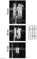
- FIG. 2 is a view illustrating a change in a field of view according to the size of the image display unit.
- the field of view in the embodiment is determined according to the size of the image display unit 130, and in order to secure a field of view of 15° or more, it is necessary to use the image display unit 130 having a size of 20 mm or more.
- FIG. 3 is a schematic view of a head mounted display according to a comparative example.
- the head mounted display 200 according to the comparative example may be the same as the head mounted display 100 according to the embodiment, except that an image display unit 230 is configured as a beam projector additionally including a lens 232 capable of condensing image display light together with a display panel 231.
- the image display light outputted by the display panel 231 according to the comparative example spreads with a wide divergence angle and is condensed by the lens 232, and then reaches the holographic optical element 220 in a narrower shape. Accordingly, light diffracted and reflected by the holographic optical element 220 may be directed toward the eye 10 of the wearer as narrow-width parallel light.
- first image display light Ld outputted from the center of the display panel 231 and second image display light Le and third image display light Lf outputted from both ends of the display panel 231 may travel while being narrowed by the lens 232 until reaching the holographic optical element 220. Therefore, the first image display light Ld, the second image display light Le, and the third image display light Lf may be incident onto the holographic optical element 220 with narrower incident ranges Ld-Ld, Le-Le, and Lf-Lf, respectively, than those of the embodiment, and may be diffracted and reflected as first reflected image display light Ld', second reflected image display light Le', and third reflected image display light Lf', respectively, by the holographic optical element 220. Then, the first reflected image display light Ld', the second reflected image display light Le', and the third reflected image display light Lf' may be directed toward the eye 10 of the wearer as the narrow-width parallel light.
- a portion, where the reflection range Ld'-Ld' of the first reflected image display light Ld', the reflection range Le'-Le' of the second reflected image display light Le', and the reflection range Lf'-Lf' of the third reflected image display light Lf' overlap one another, may be an eye motion box 2 (EMB2) where a plurality of exit pupils are located. Accordingly, it can be seen that the eye motion box 2 (EMB2), which is narrower than the eye motion box 1 (EMB1) of the embodiment, is formed.
- a wearer using the head mounted display 200 of the comparative example may not properly visually recognize image information formed by being reflected by the holographic optical element 220.
- FIG. 4 is a view illustrating an eye motion box of the head mounted display according to the embodiment
- FIG. 5 is a view illustrating an eye motion box of the head mounted display according to the comparative example.
- the size of the eye motion box (EMB) of the head mounted display is determined by the size of a reflective holographic optical element and the eye motion box (EMB) may have a size of 15 ⁇ 15 mm 2 or more.
- the size of the eye motion box (EMB) of the head mounted display according to the comparative example is limited by a lens, and even when user's eyes move only by 3 mm left and right, a cut image is seen.
- the holographic optical element 120 is preferably disposed on the eye side 111 of the wearer who wears the lens unit 110.
- the lens unit 110 is a lens for correcting the vision of the wearer
- the holographic optical element 120 when the holographic optical element 120 is disposed on the surface 112 opposite to the eye side 111 of the wearer who wears the lens unit 110, the image display light will reach the holographic optical element 120 via the lens unit 110 and be directed toward the eye 10 of the wearer via the lens unit 110 again.
- a phenomenon, in which the image display light by the holographic optical element 120 is distorted in the lens unit 110 may occur.
- the image display unit 130 is preferably disposed to be spaced apart from a first surface A, which extends along the eye side 111 of the wearer who wears the lens unit 110, in a direction toward the rear of the eye 10 of the wearer, and outputs the image display light toward the eye side 111 of the wearer who wears the lens unit 110. If the image display unit 130 is disposed on the first surface A, which extends along the eye side 111 of the wearer who wears the lens unit 110, or is disposed to be spaced apart from the first surface A in a direction toward the front of the eye 10 of the wearer from the first surface A, the image display light needs to be incident through the lateral side of the lens unit 110. In such a configuration, it is difficult to widely output the image display light and the size of the area of the holographic optical element 120 corresponding to the image display light is also limited. Therefore, it is difficult to form a wide eye motion box.
- the lens unit 110 and the image display unit 130 may be installed on at least one of eyeglass frames, goggles, and a helmet.
- FIG. 1 illustrates that the lens unit 110 and the image display unit 130 are implemented in a form corresponding to the right eye of the wearer; however, the present invention is not limited thereto and a pair of left and right lens units 110 may be provided to correspond to both eyes of the wearer, respectively, and a pair of left and right image display units 130 may be provided to correspond to both eyes of the wearer, respectively.
- the head mounted display it is possible to secure a wide eye motion box while implementing a virtual image by using a reflective holographic optical element.
Landscapes
- Physics & Mathematics (AREA)
- General Physics & Mathematics (AREA)
- Optics & Photonics (AREA)
- Diffracting Gratings Or Hologram Optical Elements (AREA)
Abstract
Description
- The present invention relates to a head mounted display.
- Recently, with an increase in interest in display devices that implement augmented reality (AR), mixed reality (MR), or virtual reality (VR), research on the display devices has been actively conducted. A display unit that implements the augmented reality (AR), the mixed reality (MR), or the virtual reality (VR) includes a diffraction light guide plate using a diffraction phenomenon based on the wave nature of light.
- As such a diffraction light guide plate, a type including a plurality of diffraction optical elements having a plurality of uneven grating patterns and a type having a transmissive holographic optical element as a photosensitive material on which an interference pattern has been recorded are mainly used.
- Meanwhile, in the case of the type having the diffraction optical element, image crosstalk may occur due to low color separation efficiency thereof. Furthermore, in the case of the type having the diffraction optical element or the transmissive holographic optical element, a large overall light loss may occur.
- On the other hand, in the case of a type having a reflective holographic optical element, color separation efficiency is high and light loss is also smaller than that of the diffraction optical element or the transmissive holographic optical element. However, when an image output unit that outputs an image to the reflective holographic optical element is used as a projector, the divergence angle of beams outputted based on individual pixels is limited, resulting in the limitation of the size of an area of the reflective holographic optical element. When the size of the area of the reflective holographic optical element is limited, even though the position of an eye is changed, the area of an eye motion box defined as an area, where an image diffractively reflected through the reflective holographic optical element is visible as is, is also limited.
- The background art described above is technology information, which has been possessed by the present inventors for deriving embodiments of the present invention or acquired in the process of deriving the embodiments of the present invention, and it may not be necessarily said that the background art is a publicly-known technology disclosed to the general public prior to the filing of the application for the embodiments of the present invention.
- Embodiments of the present invention intend to provide a head mounted display capable of securing a wide eye motion box while implementing a virtual image by using a reflective holographic optical element.
- Problems to be solved by the present invention are not limited to the aforementioned problems, and the other unmentioned problems will be clearly understood by those skilled in the art from the following description.
- An embodiment of the present invention provides a head mounted display including a lens unit disposed in front of an eye of a wearer; an holographic optical element disposed on one surface or the other surface of the lens unit; and an image display unit disposed on a lateral side of the eye of the wearer and configured to output image display light, wherein the image display unit outputs the image display light toward the holographic optical element by using at least one of a liquid crystal display panel and an organic light emitting display panel, and the holographic optical element directs the image display light, which is output from the display panel, toward the eye of the wearer through reflection using diffraction.
- According to an embodiment of the present invention, the holographic optical element may be disposed on an eye side of the wearer who wears the lens unit.
- According to an embodiment of the present invention, the display panel may be disposed to be spaced apart from a first surface, which extends along the eye side of the wearer who wears the lens unit, in a direction toward the rear of the eye of the wearer, and may output the image display light toward the eye side of the wearer who wears the lens unit.
- According to an embodiment of the present invention, the lens unit may include a transparent or translucent substrate through which external light is able to transmit from a surface opposite to an eye side of the wearer.
- According to an embodiment of the present invention, the lens unit and the image display unit may be installed on at least one of eyeglass frames, goggles, and a helmet.
- According to an embodiment of the present invention, a pair of left and right lens units may be provided to correspond to both eyes of the wearer, respectively, and a pair of left and right image display units may be provided to correspond to both eyes of the wearer, respectively.
- The head mounted display according to an embodiment of the present invention can secure a wide eye motion box while implementing a virtual image by using a reflective holographic optical element.
-
-
FIG. 1 is a schematic view of a head mounted display according to an embodiment of the present invention. -
FIG. 2 is a view illustrating a change in a field of view according to the size of an image display unit. -
FIG. 3 is a schematic view of a head mounted display according to a comparative example. -
FIG. 4 is a view illustrating an eye motion box of the head mounted display according to the embodiment. -
FIG. 5 is a view illustrating an eye motion box of the head mounted display according to the comparative example. - The present invention will become apparent by reference to the following detailed description in conjunction with the accompanying drawings. However, the present invention is not limited to such embodiments and may be realized in various forms. The embodiments to be described below are nothing but the ones provided to bring the disclosure of the present invention to perfection and assist those skilled in the art to which the present invention pertains to completely understand the scope of the present invention. The present invention is defined only by the scope of the appended claims. The terminology used herein is for the purpose of describing embodiments only and is not intended to limit the present invention. As used herein, the singular forms are intended to include the plural forms as well, unless the context clearly indicates otherwise. The terms "comprises" and/or "comprising" of stated component, step, operation and/or element, when used herein, do not exclude the presence or addition of one or more other components, steps, operations, and/or elements. The terms such as first and second may be used to describe various components, but the components are not limited by the terms. The terms are used only to distinguish one component from another component.
-
FIG. 1 is a schematic view of a head mounted display according to an embodiment of the present invention. - Referring to
FIG. 1 , the head mounteddisplay 100 according to the embodiment of the present invention is a display device that can be mounted on the head of a wearer, and may include alens unit 110, a holographicoptical element 120, and animage display unit 130. - The
lens unit 110 may be disposed in front of aneye 10 of the wearer. In an embodiment, thelens unit 110 may have a transparent or translucent substrate through whichexternal light 20 can transmit from asurface 112 opposite to aneye side 111 of the wearer. Such a substrate may be made of a high refractive transparent glass or high refractive light transparent plastic material. In the illustrated embodiment, thelens unit 110 has a flat shape; however, the present invention is not limited thereto and thelens unit 110 may have a curved shape. - The holographic
optical element 120 may be disposed on one surface or the other surface of thelens unit 110, and may be formed by recording a hologram so as to diffract incident image display light, which will be described below, in a direction designed in advance, that is, toward a side where theeye 10 of the wearer is located. In an embodiment, the holographicoptical element 120 may be formed by recording a hologram such that the image display light reaching the holographicoptical element 120 may be diffracted into parallel light and reflected. - The
image display unit 130 may be disposed on the lateral side of theeye 10 of the wearer and may output the image display light. Specifically, theimage display unit 130 may receive an electrical signal having image information and output the image display light for the image information. In an embodiment, theimage display unit 130 may include a liquid crystal display (LCD) panel or a display panel composed of organic light emitting diodes (OLEDs) (hereinafter, referred to as an organic light emitting display panel). In the present embodiment, theimage display unit 130 may output the image display light toward the holographicoptical element 120 by using at least one of the liquid crystal display panel and the organic light emitting display panel. - The holographic
optical element 120 directs the image display light, which is output from the display panel of theimage display unit 130, toward theeye 10 of the wearer through reflection using diffraction, thereby forming a virtual image of the image display light including image information. Accordingly, the wearer may recognize the virtual image as if the wearer sees an image through a screen at a certain distance. - In the present embodiment, no separate lens capable of condensing the image display light is disposed between the
image display unit 130 configured as the display panel and the holographicoptical element 120. - Accordingly, the image display light outputted by the
image display unit 130 spreads with a wide divergence angle, reaches the holographicoptical element 120, and is diffracted by the holographicoptical element 120, so that light reflected from the holographicoptical element 120 may be directed toward theeye 10 of the wearer as wide-width parallel light. - Specifically, first image display light La outputted from the center of the
image display unit 130 and second image display light Lb and third image display light Lc outputted from both ends of theimage display unit 130 may travel while spreading until reaching the holographicoptical element 120. Therefore, the first image display light La, the second image display light Lb, and the third image display light Lc may be incident onto the holographicoptical element 120 with wide-width incident ranges La-La, Lb-Lb, and Lc-Lc, respectively, and may be diffracted and reflected as first reflected image display light La', second reflected image display light Lb', and third reflected image display light Lc', respectively, by the holographicoptical element 120. Then, the first reflected image display light La', the second reflected image display light Lb', and the third reflected image display light Lc' may be directed toward theeye 10 of the wearer as the wide-width parallel light. - In such a case, a portion, where the reflection range La'-La' of the first reflected image display light La', the reflection range Lb'-Lb' of the second reflected image display light Lb', and the reflection range Lc'-Lc' of the third reflected image display light Lc' overlap one another, may be an eye motion box 1 (EMB1) where a plurality of exit pupils are located.
-
FIG. 2 is a view illustrating a change in a field of view according to the size of the image display unit. - Referring to
FIG. 2 , it can be seen that the field of view in the embodiment is determined according to the size of theimage display unit 130, and in order to secure a field of view of 15° or more, it is necessary to use theimage display unit 130 having a size of 20 mm or more. -
FIG. 3 is a schematic view of a head mounted display according to a comparative example. - The head mounted
display 200 according to the comparative example may be the same as the head mounteddisplay 100 according to the embodiment, except that animage display unit 230 is configured as a beam projector additionally including alens 232 capable of condensing image display light together with adisplay panel 231. -
- 200:
- head mounted display
- 210:
- lens unit
- 220:
- holographic optical element
- 230:
- image display unit
- The image display light outputted by the
display panel 231 according to the comparative example spreads with a wide divergence angle and is condensed by thelens 232, and then reaches the holographicoptical element 220 in a narrower shape. Accordingly, light diffracted and reflected by the holographicoptical element 220 may be directed toward theeye 10 of the wearer as narrow-width parallel light. - Specifically, first image display light Ld outputted from the center of the
display panel 231 and second image display light Le and third image display light Lf outputted from both ends of thedisplay panel 231 may travel while being narrowed by thelens 232 until reaching the holographicoptical element 220. Therefore, the first image display light Ld, the second image display light Le, and the third image display light Lf may be incident onto the holographicoptical element 220 with narrower incident ranges Ld-Ld, Le-Le, and Lf-Lf, respectively, than those of the embodiment, and may be diffracted and reflected as first reflected image display light Ld', second reflected image display light Le', and third reflected image display light Lf', respectively, by the holographicoptical element 220. Then, the first reflected image display light Ld', the second reflected image display light Le', and the third reflected image display light Lf' may be directed toward theeye 10 of the wearer as the narrow-width parallel light. - That is, a portion, where the reflection range Ld'-Ld' of the first reflected image display light Ld', the reflection range Le'-Le' of the second reflected image display light Le', and the reflection range Lf'-Lf' of the third reflected image display light Lf' overlap one another, may be an eye motion box 2 (EMB2) where a plurality of exit pupils are located. Accordingly, it can be seen that the eye motion box 2 (EMB2), which is narrower than the eye motion box 1 (EMB1) of the embodiment, is formed. In such a case, when the
eye 10 of the wearer is located within the area of the eye motion box 1 (EMB1) according to the embodiment but the position thereof is outside the area of the eye motion box 2 (EMB2) of the comparative example, a wearer using the head mounteddisplay 200 of the comparative example may not properly visually recognize image information formed by being reflected by the holographicoptical element 220. -
FIG. 4 is a view illustrating an eye motion box of the head mounted display according to the embodiment, andFIG. 5 is a view illustrating an eye motion box of the head mounted display according to the comparative example. - Referring to
FIG. 4 , the size of the eye motion box (EMB) of the head mounted display according to the embodiment is determined by the size of a reflective holographic optical element and the eye motion box (EMB) may have a size of 15 ×15 mm2 or more. - On the other hand, referring to
FIG. 5 , the size of the eye motion box (EMB) of the head mounted display according to the comparative example is limited by a lens, and even when user's eyes move only by 3 mm left and right, a cut image is seen. - Meanwhile, in the embodiment of the present invention, the holographic
optical element 120 is preferably disposed on theeye side 111 of the wearer who wears thelens unit 110. In a case that thelens unit 110 is a lens for correcting the vision of the wearer, when the holographicoptical element 120 is disposed on thesurface 112 opposite to theeye side 111 of the wearer who wears thelens unit 110, the image display light will reach the holographicoptical element 120 via thelens unit 110 and be directed toward theeye 10 of the wearer via thelens unit 110 again. In such a case, a phenomenon, in which the image display light by the holographicoptical element 120 is distorted in thelens unit 110, may occur. - In the embodiment of the present invention, the
image display unit 130 is preferably disposed to be spaced apart from a first surface A, which extends along theeye side 111 of the wearer who wears thelens unit 110, in a direction toward the rear of theeye 10 of the wearer, and outputs the image display light toward theeye side 111 of the wearer who wears thelens unit 110. If theimage display unit 130 is disposed on the first surface A, which extends along theeye side 111 of the wearer who wears thelens unit 110, or is disposed to be spaced apart from the first surface A in a direction toward the front of theeye 10 of the wearer from the first surface A, the image display light needs to be incident through the lateral side of thelens unit 110. In such a configuration, it is difficult to widely output the image display light and the size of the area of the holographicoptical element 120 corresponding to the image display light is also limited. Therefore, it is difficult to form a wide eye motion box. - In the embodiment of the present invention, the
lens unit 110 and theimage display unit 130 may be installed on at least one of eyeglass frames, goggles, and a helmet. - Furthermore,
FIG. 1 illustrates that thelens unit 110 and theimage display unit 130 are implemented in a form corresponding to the right eye of the wearer; however, the present invention is not limited thereto and a pair of left andright lens units 110 may be provided to correspond to both eyes of the wearer, respectively, and a pair of left and rightimage display units 130 may be provided to correspond to both eyes of the wearer, respectively. - In accordance with the head mounted display according to the embodiment of the present invention, it is possible to secure a wide eye motion box while implementing a virtual image by using a reflective holographic optical element.
- Although the present invention has been described in relation to the preferred embodiment described above, various corrections or modifications can be made without departing from the subject matter and scope of the disclosure. Therefore, the appended claims will include such corrections or modifications as long as they belong to the subject matter of the present invention.
-
- 100:
- head mounted display
- 110:
- lens unit
- 120:
- holographic optical element
- 130:
- image display unit
- A:
- first surface
- EMB1, EMB2:
- eye motion box
Claims (6)
- A head mounted display comprising:a lens unit disposed in front of an eye of a wearer;an holographic optical element disposed on one surface or the other surface of the lens unit; andan image display unit disposed on a lateral side of the eye of the wearer and configured to output image display light,wherein the image display unit outputs the image display light toward the holographic optical element by using at least one of a liquid crystal display panel and an organic light emitting display panel, andthe holographic optical element directs the image display light, which is output from the display panel, toward the eye of the wearer through reflection using diffraction.
- The head mounted display according to claim 1, wherein the holographic optical element is disposed on an eye side of the wearer who wears the lens unit.
- The head mounted display according to claim 1, wherein the display panel is disposed to be spaced apart from a first surface, which extends along the eye side of the wearer who wears the lens unit, in a direction toward rear of the eye of the wearer, and outputs the image display light toward the eye side of the wearer who wears the lens unit.
- The head mounted display according to claim 1, wherein the lens unit includes a transparent or translucent substrate through which external light is able to transmit from a surface opposite to an eye side of the wearer.
- The head mounted display according to claim 1, wherein the lens unit and the image display unit are installed on at least one of eyeglass frames, goggles, and a helmet.
- The head mounted display according to claim 1, wherein a pair of left and right lens units are provided to correspond to both eyes of the wearer, respectively, and a pair of left and right image display units are provided to correspond to both eyes of the wearer, respectively.
Applications Claiming Priority (3)
| Application Number | Priority Date | Filing Date | Title |
|---|---|---|---|
| KR20190121204 | 2019-09-30 | ||
| KR1020200095887A KR102570187B1 (en) | 2019-09-30 | 2020-07-31 | Head mounted display |
| PCT/KR2020/010499 WO2021066314A1 (en) | 2019-09-30 | 2020-08-07 | Head mounted display |
Publications (2)
| Publication Number | Publication Date |
|---|---|
| EP3907551A1 true EP3907551A1 (en) | 2021-11-10 |
| EP3907551A4 EP3907551A4 (en) | 2022-03-30 |
Family
ID=75469476
Family Applications (1)
| Application Number | Title | Priority Date | Filing Date |
|---|---|---|---|
| EP20872066.4A Pending EP3907551A4 (en) | 2019-09-30 | 2020-08-07 | VISUAL HEADSET |
Country Status (5)
| Country | Link |
|---|---|
| US (1) | US12393028B2 (en) |
| EP (1) | EP3907551A4 (en) |
| JP (2) | JP7276916B2 (en) |
| KR (1) | KR102570187B1 (en) |
| CN (1) | CN113287055A (en) |
Families Citing this family (1)
| Publication number | Priority date | Publication date | Assignee | Title |
|---|---|---|---|---|
| KR102843328B1 (en) * | 2019-10-24 | 2025-08-05 | 삼성전자주식회사 | Display apparatus having wide viewing window |
Family Cites Families (37)
| Publication number | Priority date | Publication date | Assignee | Title |
|---|---|---|---|---|
| KR960016722A (en) | 1994-11-17 | 1996-06-17 | 윤희철 | Method for preparing zirconium phosphate containing antimicrobial metal ions |
| JPH10319240A (en) | 1997-05-22 | 1998-12-04 | Fuji Xerox Co Ltd | Head-mounted display |
| JP3678264B2 (en) | 1998-03-12 | 2005-08-03 | 富士ゼロックス株式会社 | Video display device |
| JPH11326823A (en) * | 1998-05-18 | 1999-11-26 | Sony Corp | Virtual image observation optical system |
| JP4968362B2 (en) | 2000-09-11 | 2012-07-04 | コニカミノルタホールディングス株式会社 | Video display device |
| DE10103922A1 (en) | 2001-01-30 | 2002-08-01 | Physoptics Opto Electronic Gmb | Interactive data viewing and operating system |
| JP2004341027A (en) * | 2003-05-13 | 2004-12-02 | Minolta Co Ltd | Image display system |
| JP2005099751A (en) | 2003-08-22 | 2005-04-14 | Fuji Photo Film Co Ltd | Composition for hologram recording material, hologram recording material and hologram recording method |
| JP4591006B2 (en) | 2004-09-21 | 2010-12-01 | コニカミノルタホールディングス株式会社 | Observation optical system and image display device having holographic reflection surface |
| JP2009244869A (en) | 2008-03-11 | 2009-10-22 | Panasonic Corp | Display apparatus, display method, goggle-type head-mounted display, and vehicle |
| US20100149073A1 (en) | 2008-11-02 | 2010-06-17 | David Chaum | Near to Eye Display System and Appliance |
| JP2010072150A (en) | 2008-09-17 | 2010-04-02 | Konica Minolta Holdings Inc | Video display apparatus and head mount display |
| JP2010139589A (en) | 2008-12-10 | 2010-06-24 | Konica Minolta Opto Inc | Video image display apparatus and head mounted display |
| CN101726856B (en) | 2009-12-18 | 2012-06-06 | 中航华东光电有限公司 | Onboard goggle-type helmet display optical system |
| WO2011155357A1 (en) | 2010-06-07 | 2011-12-15 | コニカミノルタオプト株式会社 | Video display device, head-mounted display and head-up display |
| CN102033319B (en) | 2010-10-25 | 2015-07-15 | 北京理工大学 | Oxyopter type display device using holographic elements |
| JP5118266B2 (en) | 2011-03-25 | 2013-01-16 | パナソニック株式会社 | Display device |
| KR101969353B1 (en) | 2012-10-18 | 2019-04-16 | 엘지전자 주식회사 | Optical device and Wearable display |
| US8947783B2 (en) | 2013-01-02 | 2015-02-03 | Google Inc. | Optical combiner for near-eye display |
| KR20150136601A (en) | 2013-03-25 | 2015-12-07 | 에꼴 뽈리떼끄닉 뻬데랄 드 로잔느 (으뻬에프엘) | Method for displaying an image projected from a head-worn display with multiple exit pupils |
| CN105899997B (en) | 2014-03-17 | 2019-02-15 | 松下知识产权经营株式会社 | display device |
| JP6413291B2 (en) | 2014-03-27 | 2018-10-31 | セイコーエプソン株式会社 | Virtual image display device and head mounted display |
| KR20160143749A (en) * | 2014-04-09 | 2016-12-14 | 쓰리엠 이노베이티브 프로퍼티즈 컴파니 | Head mounted display and low conspicuity pupil illuminator |
| WO2016017966A1 (en) * | 2014-07-29 | 2016-02-04 | Samsung Electronics Co., Ltd. | Method of displaying image via head mounted display device and head mounted display device therefor |
| JP2016161670A (en) | 2015-02-27 | 2016-09-05 | セイコーエプソン株式会社 | Image display device |
| JP6534302B2 (en) | 2015-06-19 | 2019-06-26 | 株式会社Nttドコモ | Video display device |
| WO2017005614A1 (en) * | 2015-07-03 | 2017-01-12 | Essilor International (Compagnie Generale D'optique) | Methods and systems for augmented reality |
| US10146054B2 (en) * | 2015-07-06 | 2018-12-04 | Google Llc | Adding prescriptive correction to eyepieces for see-through head wearable displays |
| US10437071B2 (en) | 2015-10-12 | 2019-10-08 | North Inc. | Adjustable pupil distance wearable display |
| CN105572877B (en) | 2016-02-03 | 2018-11-09 | 上海群英软件有限公司 | A kind of wear-type augmented reality intelligent display device |
| US9964768B2 (en) | 2016-03-04 | 2018-05-08 | Sharp Kabushiki Kaisha | Head mounted display using spatial light modulator to generate a holographic image |
| CN205982840U (en) | 2016-08-30 | 2017-02-22 | 北京亮亮视野科技有限公司 | Very three -dimensional holographical display wear -type visual device |
| WO2018057660A2 (en) | 2016-09-20 | 2018-03-29 | Apple Inc. | Augmented reality system |
| CN107479197B (en) | 2017-07-31 | 2023-07-04 | 上海永微信息科技有限公司 | Holographic near-eye display system |
| CN207396866U (en) | 2017-07-31 | 2018-05-22 | 上海永微信息科技有限公司 | Holographic near-eye display system |
| US11231581B2 (en) * | 2017-09-27 | 2022-01-25 | Magic Leap, Inc. | Near eye 3D display with separate phase and amplitude modulators |
| EP3502763B1 (en) | 2017-12-22 | 2023-02-01 | Essilor International | Head mounted device comprising a fourier hologram |
-
2020
- 2020-07-31 KR KR1020200095887A patent/KR102570187B1/en active Active
- 2020-08-07 JP JP2021539518A patent/JP7276916B2/en active Active
- 2020-08-07 EP EP20872066.4A patent/EP3907551A4/en active Pending
- 2020-08-07 US US17/430,955 patent/US12393028B2/en active Active
- 2020-08-07 CN CN202080008542.7A patent/CN113287055A/en active Pending
-
2023
- 2023-02-03 JP JP2023015458A patent/JP2023057103A/en active Pending
Also Published As
| Publication number | Publication date |
|---|---|
| US12393028B2 (en) | 2025-08-19 |
| KR20210038304A (en) | 2021-04-07 |
| US20220146829A1 (en) | 2022-05-12 |
| CN113287055A (en) | 2021-08-20 |
| JP7276916B2 (en) | 2023-05-18 |
| JP2023057103A (en) | 2023-04-20 |
| JP2022516940A (en) | 2022-03-03 |
| EP3907551A4 (en) | 2022-03-30 |
| KR102570187B1 (en) | 2023-08-25 |
Similar Documents
| Publication | Publication Date | Title |
|---|---|---|
| EP3345040B1 (en) | Diffractive backlight display and system | |
| US10545337B2 (en) | See-through holographic display apparatus | |
| KR102594052B1 (en) | Method and system for waveguide projector with wide field of view | |
| EP3241053B1 (en) | Waveguide-based display system | |
| US9442291B1 (en) | Segmented diffractive optical elements for a head wearable display | |
| KR102877082B1 (en) | Near eye display device, agreegated reality glasses and method of its operation | |
| US12332443B2 (en) | Near-eye display device, augmented reality glasses including same, and operating method therefor | |
| US11500213B2 (en) | Head-mounted display capable of preventing damage of an image display apparatus | |
| JP7753489B2 (en) | Eyewear device and method | |
| US12393028B2 (en) | Head mounted display | |
| US12235448B2 (en) | Head mounted display | |
| CN118363173A (en) | Virtual image display device and head mounted display device | |
| WO2021066314A1 (en) | Head mounted display | |
| KR20250116778A (en) | Display devices having grids with gradient edges | |
| HK1250790A1 (en) | Diffractive backlight display and system |
Legal Events
| Date | Code | Title | Description |
|---|---|---|---|
| STAA | Information on the status of an ep patent application or granted ep patent |
Free format text: STATUS: THE INTERNATIONAL PUBLICATION HAS BEEN MADE |
|
| PUAI | Public reference made under article 153(3) epc to a published international application that has entered the european phase |
Free format text: ORIGINAL CODE: 0009012 |
|
| STAA | Information on the status of an ep patent application or granted ep patent |
Free format text: STATUS: REQUEST FOR EXAMINATION WAS MADE |
|
| 17P | Request for examination filed |
Effective date: 20210805 |
|
| AK | Designated contracting states |
Kind code of ref document: A1 Designated state(s): AL AT BE BG CH CY CZ DE DK EE ES FI FR GB GR HR HU IE IS IT LI LT LU LV MC MK MT NL NO PL PT RO RS SE SI SK SM TR |
|
| A4 | Supplementary search report drawn up and despatched |
Effective date: 20220228 |
|
| RIC1 | Information provided on ipc code assigned before grant |
Ipc: G02B 5/32 20060101ALI20220222BHEP Ipc: G02B 27/01 20060101AFI20220222BHEP |
|
| DAV | Request for validation of the european patent (deleted) | ||
| DAX | Request for extension of the european patent (deleted) | ||
| STAA | Information on the status of an ep patent application or granted ep patent |
Free format text: STATUS: EXAMINATION IS IN PROGRESS |
|
| 17Q | First examination report despatched |
Effective date: 20240909 |