EP3907521A1 - Methods and systems for determining alignment parameters of a radar sensor - Google Patents
Methods and systems for determining alignment parameters of a radar sensor Download PDFInfo
- Publication number
- EP3907521A1 EP3907521A1 EP20172809.4A EP20172809A EP3907521A1 EP 3907521 A1 EP3907521 A1 EP 3907521A1 EP 20172809 A EP20172809 A EP 20172809A EP 3907521 A1 EP3907521 A1 EP 3907521A1
- Authority
- EP
- European Patent Office
- Prior art keywords
- misalignment
- parameters
- implemented method
- computer implemented
- computer
- Prior art date
- Legal status (The legal status is an assumption and is not a legal conclusion. Google has not performed a legal analysis and makes no representation as to the accuracy of the status listed.)
- Withdrawn
Links
Images




Classifications
-
- G—PHYSICS
- G01—MEASURING; TESTING
- G01S—RADIO DIRECTION-FINDING; RADIO NAVIGATION; DETERMINING DISTANCE OR VELOCITY BY USE OF RADIO WAVES; LOCATING OR PRESENCE-DETECTING BY USE OF THE REFLECTION OR RERADIATION OF RADIO WAVES; ANALOGOUS ARRANGEMENTS USING OTHER WAVES
- G01S7/00—Details of systems according to groups G01S13/00, G01S15/00, G01S17/00
- G01S7/02—Details of systems according to groups G01S13/00, G01S15/00, G01S17/00 of systems according to group G01S13/00
- G01S7/40—Means for monitoring or calibrating
-
- G—PHYSICS
- G01—MEASURING; TESTING
- G01S—RADIO DIRECTION-FINDING; RADIO NAVIGATION; DETERMINING DISTANCE OR VELOCITY BY USE OF RADIO WAVES; LOCATING OR PRESENCE-DETECTING BY USE OF THE REFLECTION OR RERADIATION OF RADIO WAVES; ANALOGOUS ARRANGEMENTS USING OTHER WAVES
- G01S13/00—Systems using the reflection or reradiation of radio waves, e.g. radar systems; Analogous systems using reflection or reradiation of waves whose nature or wavelength is irrelevant or unspecified
- G01S13/88—Radar or analogous systems specially adapted for specific applications
- G01S13/93—Radar or analogous systems specially adapted for specific applications for anti-collision purposes
- G01S13/931—Radar or analogous systems specially adapted for specific applications for anti-collision purposes of land vehicles
-
- G—PHYSICS
- G01—MEASURING; TESTING
- G01S—RADIO DIRECTION-FINDING; RADIO NAVIGATION; DETERMINING DISTANCE OR VELOCITY BY USE OF RADIO WAVES; LOCATING OR PRESENCE-DETECTING BY USE OF THE REFLECTION OR RERADIATION OF RADIO WAVES; ANALOGOUS ARRANGEMENTS USING OTHER WAVES
- G01S7/00—Details of systems according to groups G01S13/00, G01S15/00, G01S17/00
- G01S7/02—Details of systems according to groups G01S13/00, G01S15/00, G01S17/00 of systems according to group G01S13/00
- G01S7/40—Means for monitoring or calibrating
- G01S7/4004—Means for monitoring or calibrating of parts of a radar system
- G01S7/4026—Antenna boresight
-
- G—PHYSICS
- G01—MEASURING; TESTING
- G01S—RADIO DIRECTION-FINDING; RADIO NAVIGATION; DETERMINING DISTANCE OR VELOCITY BY USE OF RADIO WAVES; LOCATING OR PRESENCE-DETECTING BY USE OF THE REFLECTION OR RERADIATION OF RADIO WAVES; ANALOGOUS ARRANGEMENTS USING OTHER WAVES
- G01S13/00—Systems using the reflection or reradiation of radio waves, e.g. radar systems; Analogous systems using reflection or reradiation of waves whose nature or wavelength is irrelevant or unspecified
- G01S13/02—Systems using reflection of radio waves, e.g. primary radar systems; Analogous systems
- G01S13/06—Systems determining position data of a target
- G01S13/42—Simultaneous measurement of distance and other co-ordinates
-
- G—PHYSICS
- G01—MEASURING; TESTING
- G01S—RADIO DIRECTION-FINDING; RADIO NAVIGATION; DETERMINING DISTANCE OR VELOCITY BY USE OF RADIO WAVES; LOCATING OR PRESENCE-DETECTING BY USE OF THE REFLECTION OR RERADIATION OF RADIO WAVES; ANALOGOUS ARRANGEMENTS USING OTHER WAVES
- G01S13/00—Systems using the reflection or reradiation of radio waves, e.g. radar systems; Analogous systems using reflection or reradiation of waves whose nature or wavelength is irrelevant or unspecified
- G01S13/02—Systems using reflection of radio waves, e.g. primary radar systems; Analogous systems
- G01S13/50—Systems of measurement based on relative movement of target
- G01S13/58—Velocity or trajectory determination systems; Sense-of-movement determination systems
- G01S13/60—Velocity or trajectory determination systems; Sense-of-movement determination systems wherein the transmitter and receiver are mounted on the moving object, e.g. for determining ground speed, drift angle, ground track
-
- G—PHYSICS
- G01—MEASURING; TESTING
- G01S—RADIO DIRECTION-FINDING; RADIO NAVIGATION; DETERMINING DISTANCE OR VELOCITY BY USE OF RADIO WAVES; LOCATING OR PRESENCE-DETECTING BY USE OF THE REFLECTION OR RERADIATION OF RADIO WAVES; ANALOGOUS ARRANGEMENTS USING OTHER WAVES
- G01S13/00—Systems using the reflection or reradiation of radio waves, e.g. radar systems; Analogous systems using reflection or reradiation of waves whose nature or wavelength is irrelevant or unspecified
- G01S13/87—Combinations of radar systems, e.g. primary radar and secondary radar
-
- G—PHYSICS
- G01—MEASURING; TESTING
- G01S—RADIO DIRECTION-FINDING; RADIO NAVIGATION; DETERMINING DISTANCE OR VELOCITY BY USE OF RADIO WAVES; LOCATING OR PRESENCE-DETECTING BY USE OF THE REFLECTION OR RERADIATION OF RADIO WAVES; ANALOGOUS ARRANGEMENTS USING OTHER WAVES
- G01S7/00—Details of systems according to groups G01S13/00, G01S15/00, G01S17/00
- G01S7/02—Details of systems according to groups G01S13/00, G01S15/00, G01S17/00 of systems according to group G01S13/00
- G01S7/41—Details of systems according to groups G01S13/00, G01S15/00, G01S17/00 of systems according to group G01S13/00 using analysis of echo signal for target characterisation; Target signature; Target cross-section
- G01S7/415—Identification of targets based on measurements of movement associated with the target
-
- G—PHYSICS
- G01—MEASURING; TESTING
- G01S—RADIO DIRECTION-FINDING; RADIO NAVIGATION; DETERMINING DISTANCE OR VELOCITY BY USE OF RADIO WAVES; LOCATING OR PRESENCE-DETECTING BY USE OF THE REFLECTION OR RERADIATION OF RADIO WAVES; ANALOGOUS ARRANGEMENTS USING OTHER WAVES
- G01S13/00—Systems using the reflection or reradiation of radio waves, e.g. radar systems; Analogous systems using reflection or reradiation of waves whose nature or wavelength is irrelevant or unspecified
- G01S13/02—Systems using reflection of radio waves, e.g. primary radar systems; Analogous systems
- G01S13/50—Systems of measurement based on relative movement of target
- G01S13/58—Velocity or trajectory determination systems; Sense-of-movement determination systems
- G01S13/589—Velocity or trajectory determination systems; Sense-of-movement determination systems measuring the velocity vector
-
- G—PHYSICS
- G01—MEASURING; TESTING
- G01S—RADIO DIRECTION-FINDING; RADIO NAVIGATION; DETERMINING DISTANCE OR VELOCITY BY USE OF RADIO WAVES; LOCATING OR PRESENCE-DETECTING BY USE OF THE REFLECTION OR RERADIATION OF RADIO WAVES; ANALOGOUS ARRANGEMENTS USING OTHER WAVES
- G01S13/00—Systems using the reflection or reradiation of radio waves, e.g. radar systems; Analogous systems using reflection or reradiation of waves whose nature or wavelength is irrelevant or unspecified
- G01S13/88—Radar or analogous systems specially adapted for specific applications
- G01S13/93—Radar or analogous systems specially adapted for specific applications for anti-collision purposes
- G01S13/931—Radar or analogous systems specially adapted for specific applications for anti-collision purposes of land vehicles
- G01S2013/932—Radar or analogous systems specially adapted for specific applications for anti-collision purposes of land vehicles using own vehicle data, e.g. ground speed, steering wheel direction
-
- G—PHYSICS
- G01—MEASURING; TESTING
- G01S—RADIO DIRECTION-FINDING; RADIO NAVIGATION; DETERMINING DISTANCE OR VELOCITY BY USE OF RADIO WAVES; LOCATING OR PRESENCE-DETECTING BY USE OF THE REFLECTION OR RERADIATION OF RADIO WAVES; ANALOGOUS ARRANGEMENTS USING OTHER WAVES
- G01S13/00—Systems using the reflection or reradiation of radio waves, e.g. radar systems; Analogous systems using reflection or reradiation of waves whose nature or wavelength is irrelevant or unspecified
- G01S13/88—Radar or analogous systems specially adapted for specific applications
- G01S13/93—Radar or analogous systems specially adapted for specific applications for anti-collision purposes
- G01S13/931—Radar or analogous systems specially adapted for specific applications for anti-collision purposes of land vehicles
- G01S2013/9327—Sensor installation details
- G01S2013/93271—Sensor installation details in the front of the vehicles
-
- G—PHYSICS
- G01—MEASURING; TESTING
- G01S—RADIO DIRECTION-FINDING; RADIO NAVIGATION; DETERMINING DISTANCE OR VELOCITY BY USE OF RADIO WAVES; LOCATING OR PRESENCE-DETECTING BY USE OF THE REFLECTION OR RERADIATION OF RADIO WAVES; ANALOGOUS ARRANGEMENTS USING OTHER WAVES
- G01S7/00—Details of systems according to groups G01S13/00, G01S15/00, G01S17/00
- G01S7/02—Details of systems according to groups G01S13/00, G01S15/00, G01S17/00 of systems according to group G01S13/00
- G01S7/40—Means for monitoring or calibrating
- G01S7/4004—Means for monitoring or calibrating of parts of a radar system
- G01S7/4026—Antenna boresight
- G01S7/403—Antenna boresight in azimuth, i.e. in the horizontal plane
-
- G—PHYSICS
- G01—MEASURING; TESTING
- G01S—RADIO DIRECTION-FINDING; RADIO NAVIGATION; DETERMINING DISTANCE OR VELOCITY BY USE OF RADIO WAVES; LOCATING OR PRESENCE-DETECTING BY USE OF THE REFLECTION OR RERADIATION OF RADIO WAVES; ANALOGOUS ARRANGEMENTS USING OTHER WAVES
- G01S7/00—Details of systems according to groups G01S13/00, G01S15/00, G01S17/00
- G01S7/02—Details of systems according to groups G01S13/00, G01S15/00, G01S17/00 of systems according to group G01S13/00
- G01S7/40—Means for monitoring or calibrating
- G01S7/4004—Means for monitoring or calibrating of parts of a radar system
- G01S7/4026—Antenna boresight
- G01S7/4034—Antenna boresight in elevation, i.e. in the vertical plane
-
- G—PHYSICS
- G01—MEASURING; TESTING
- G01S—RADIO DIRECTION-FINDING; RADIO NAVIGATION; DETERMINING DISTANCE OR VELOCITY BY USE OF RADIO WAVES; LOCATING OR PRESENCE-DETECTING BY USE OF THE REFLECTION OR RERADIATION OF RADIO WAVES; ANALOGOUS ARRANGEMENTS USING OTHER WAVES
- G01S7/00—Details of systems according to groups G01S13/00, G01S15/00, G01S17/00
- G01S7/02—Details of systems according to groups G01S13/00, G01S15/00, G01S17/00 of systems according to group G01S13/00
- G01S7/40—Means for monitoring or calibrating
- G01S7/4052—Means for monitoring or calibrating by simulation of echoes
- G01S7/4082—Means for monitoring or calibrating by simulation of echoes using externally generated reference signals, e.g. via remote reflector or transponder
- G01S7/4091—Means for monitoring or calibrating by simulation of echoes using externally generated reference signals, e.g. via remote reflector or transponder during normal radar operation
Definitions
- the present disclosure relates to methods and systems for determining alignment parameters of a radar sensor.
- Radar-sensors for example in automotive applications, need to be aligned with the chassis of a host-vehicle so that the location of detected objects is accurately known. Alignment procedures performed when the host-vehicle is assembled are not able to compensate for pitch or elevation errors caused by heavy cargo and yaw, azimuth or roll errors caused by miss-alignment of the wheels or chassis of the host-vehicle which may cause 'crabbing' or 'dog-tracking' by the host-vehicle while traveling.
- the present disclosure provides a computer implemented method, a radar system, a computer system, a vehicle, and a non-transitory computer readable medium according to the independent claims. Embodiments are given in the subclaims, the description and the drawings.
- the present disclosure is directed at a computer implemented method for determining alignment parameters of a radar sensor, the method comprising the following steps performed (in other words: carried out) by computer hardware components: determining measurement data using the radar sensor, the measurement data comprising a range-rate measurement, an azimuth measurement, and an elevation measurement; determining a velocity (in other words: speed) of the radar sensor using a velocity sensor; and determining the misalignment parameters based on the measurement data and the velocity, the misalignment parameters comprising an azimuth misalignment, an elevation misalignment, and a roll misalignment.
- misalignment parameters may be determined by comparing a velocity determined by a velocity sensor (which may be independent from the radar sensor) and velocity information which is determined based on radar measurement data.
- the measurements data may be related to the radar sensor, for example to a radar sensor mounted on a vehicle (for example at least partially autonomously driving vehicle, for example car), for example on the chassis of the vehicle.
- the velocity sensor may be external to the radar sensor; for example, the velocity sensor may be the velocity sensor of a vehicle, for example based on odometry measurements, gyroscope measurements, and/or acceleration measurements.
- the misalignment parameters further comprise a speed-scaling error.
- the computer implemented method further comprises the following step carried out by the computer hardware components: determining system parameters, the system parameters comprising at least one of a desired azimuth mounting angle, a desired elevation mounting angle, and a desired roll mounting angle; wherein the misalignment parameters are determined further based on the system parameters.
- the system parameters may be set by the manufacturer of the system (for example vehicle) on which the radar sensor is provided.
- the system parameters may describe or define how the radar sensor is provided (for example mounted) in the vehicle.
- the measurement data is related to a plurality of objects external to the radar sensor.
- measurement results related to at least three objects may be provided.
- measurement results related to at least four objects may be provided.
- measurement results related to at least five objects may be provided.
- the number of objects may be chosen so that the system for determining the misalignment parameters is at least not under-determined, for example so that the system is over-determined (i.e. more measurement results may be available than unknown misalignment parameters are to be determined; this may allow for implicit correction of measurement inaccuracies or measurement errors, for example by using regression methods to determine the misalignment parameters).
- the objects may be provided outside a vehicle in which the radar sensor is provided.
- the plurality of objects are stationary.
- the velocity determined by the velocity sensor is identical to the (relative) velocity of the stationary objects (relative to the radar sensor). This may be used for determining the misalignment parameters by determining the misalignment parameters so that the velocity determined based on the radar measurements is in agreement with the velocity determined by the velocity sensor (for example so that the difference between the velocity determined based on the radar measurements is in agreement with the velocity determined by the velocity sensor is minimized).
- the misalignment parameters are determined based on an iterative method.
- a closed-form solution to the determination of the misalignment parameters may not be available, or may be numerically instable.
- An iterative method may be used, starting from an initial estimate (or guess), for example with all misalignment parameters set to a default value (for example 0).
- the estimate values may be iteratively updated.
- the misalignment parameters may already be of reasonable accuracy after one iteration. Depending on the resources like time and computational power, more than one iteration may be performed.
- the iterations may continue until a pre-determined stop criterion is reached, for example a maximum time available for the determination of the misalignment parameters, or a pre-determined accuracy of the misalignment parameters (which may for example be determined based on how much (for example absolutely or relatively) the estimates for the misalignment parameters change from one iteration to the next iteration).
- a pre-determined stop criterion for example a maximum time available for the determination of the misalignment parameters, or a pre-determined accuracy of the misalignment parameters (which may for example be determined based on how much (for example absolutely or relatively) the estimates for the misalignment parameters change from one iteration to the next iteration).
- the misalignment parameters are determined based on an optimization method.
- the optimization method may optimize the misalignment parameters so that the difference between the velocity measured by the velocity sensor and the velocity which is determined based on the measurement data is minimized.
- the optimization method may determine the misalignment parameters from an overdetermined system (wherein more measurements, for example related to a plurality of objects, are available than would be required for a closed form determination of the misalignment parameters).
- the optimization method may use the Jacobian matrix, including partial derivatives of the modeled output with respect to the misalignment parameters.
- the misalignment parameters are determined based on a non-linear least squares regression method. According to another aspect, the misalignment parameters are determined based on an non-linear total least squares regression method.
- the misalignment parameters are determined based on filtering.
- the misalignment parameters that have been determined based on the optimization or regression method may be subject to filtering, for example Kalman filtering, to further improve the misalignment parameters.
- the overall performance of the alignment may be improved, which may have a positive impact on the performance of further radar processing.
- the present disclosure is directed at a computer implemented method for determining corrected measurement data, the method comprising the following steps carried out by computer hardware components: determining measurement data using a radar sensor; correcting the measurement data to obtain the corrected measurement data based on misalignment parameters determined according to the computer-implemented method described herein.
- the control of the radar sensor (for example the area in which the radar sensor is to determine measurements) may be adjusted (for example to the desired area or desired field of view).
- the present disclosure is directed at a computer system, said computer system comprising a plurality of computer hardware components configured to carry out several or all steps of the computer implemented method described herein.
- the computer system can be part of a vehicle.
- the computer system may comprise a plurality of computer hardware components (for example a processor, for example processing unit or processing network, at least one memory, for example memory unit or memory network, and at least one non-transitory data storage). It will be understood that further computer hardware components may be provided and used for carrying out steps of the computer implemented method in the computer system.
- the non-transitory data storage and/or the memory unit may comprise a computer program for instructing the computer to perform several or all steps or aspects of the computer implemented method described herein, for example using the processing unit and the at least one memory unit.
- the present disclosure is directed at a radar system comprising a radar sensor for which the misalignment parameters are determined according to the computer implemented method described herein.
- the present disclosure is directed at a vehicle comprising the radar system described herein.
- the present disclosure is directed at a non-transitory computer readable medium comprising instructions for carrying out several or all steps or aspects of the computer implemented method described herein.
- the computer readable medium may be configured as: an optical medium, such as a compact disc (CD) or a digital versatile disk (DVD); a magnetic medium, such as a hard disk drive (HDD); a solid state drive (SSD); a read only memory (ROM), such as a flash memory; or the like.
- the computer readable medium may be configured as a data storage that is accessible via a data connection, such as an internet connection.
- the computer readable medium may, for example, be an online data repository or a cloud storage.
- the present disclosure is also directed at a computer program for instructing a computer to perform several or all steps or aspects of the computer implemented method described herein.
- Radar alignment is a process of determining the angular misalignment of radar facing direction. Correction of those mounting errors may be crucial for proper operation of radar based tracking methods and most of the feature functions that operate on detections or tracked objects provided by a radar sensor.
- Two main classes of methods/approaches aimed at solving misalignment problem are:
- Fig. 1A and Fig. 1B shows illustrations 100 and 150 of misalignment and radar field-of-view relationship.
- Fig. 1A shows an illustration 100 of a radar field-of-view 110 when misaligned in azimuth (along a horizontal line 102) and elevation (along a vertical split line 104 at the front of the vehicle, which corresponds to 0 deg).
- the ideal (or desired or assumed) facing angle 106 is different from the real (or actual) facing angle 108, so that a misalignment 112 is present.
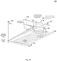
- Fig. 1B shows an illustration 150 of a three-dimensional misalignment in azimuth ( ⁇ ), elevation ( ⁇ ), and roll ( ⁇ ). Coordinates axis are illustrated in the vehicle coordinate system (VCS), i.e. X VCS 152, Y VCS 154, and Z VCS 156.
- VCS vehicle coordinate system
- the ground plane 158 is illustrated.
- the radar sensor may be mounted above ground plane 158 at the origin of the vehicle coordinate system. The desired boresight direction for perfect alignment would coincide with X VCS 152.
- the actual boresight direction 160 is different from X VCS 152 due to the misalignment, and the difference between the actual boresight direction 160 and X VCS 152 may be described by the three-dimensional misalignment in azimuth ( ⁇ ), elevation ( ⁇ ), and roll ( ⁇ ). Due to the misalignment, the desired FOV 162 (field of view) may be different from the actual FOV 164. However, the desired FOV 162 may be obtained by correction based on misalignment parameters based on the actual FOV 164.
- V X V Xm 1 + V c
- V Y V Ym 1 + V c
- V Z V Zm 1 + V c
- Various methods such as iterative non-linear least squares regression or error-in-variables methods, may be used to determine the unknown parameters. The parameters found by these methods may then further be refined by filtering in time methods such as Kalman filter.
- Fig. 2 shows a flow diagram 200 illustrating an overview of methods for determining alignment parameters according to various embodiments (either not taking into account a misalignment in roll angle, or taking into account a misalignment in roll angle, like will be described in more detail below).
- data acquisition may be carried out, which may include stationary detections, vehicle velocities, and radar information.
- regression may be carried out, for example including estimation of azimuth misalignment, estimation of elevation misalignment, estimation of roll misalignment (as will be described in more detail below), and estimation of speed-scaling error.
- filtering for example using a Kalman filter
- filtering for example using a Kalman filter
- Roll angle misalignment may influence the azimuth-elevation misalignment calculation itself.
- Fig. 3 shows an illustration 300 of a radar field-of-view after introduction of roll misalignment, similar to what is shown in Fig. 1A (wherein in Fig. 1A no roll misalignment is illustrated).
- Illustration 302 in the left portion of Fig. 3 shows an illustration from the ground perspective, and illustration 304 in the right portion of Fig. 3 shows an illustration from the sensor perspective.
- the azimuth misalignment may be taken as 0 (zero) or close to 0, and the elevation misalignment may be estimated to be greater than the correct value of the elevation misalignment, due to the fact that the ideal facing angle is exactly below the reported facing angle as seen by the radar sensor. This may result in finding wrong misalignment parameters, for example zero azimuth misalignment and too high elevation misalignment value.
- the impact of the roll angle misalignment may be almost unobservable for small angles (for example less than 1 [deg]), and may be growing exponentially with the roll, introducing highest error at the corners of field-of-view.
- a 30 [deg] radar roll i.e. a misalignment of the radar sensor in roll angle of 30 deg
- the error is reducing the field of view of radar by half (the sensor may observe ground in near vicinity of front of the vehicle, and the sky above on the opposite side of FOV; however, both the ground and the sky regions are irrelevant from the active safety methods perspective).
- a significant part of important information about objects located approximately 0.5 m above the ground is missed.
- an undetected roll angle misalignment may make the azimuth and elevation misalignment angles unreliable.
- an object at 60 deg azimuth and 5 deg elevation under influence of 5 deg sensor roll misalignment will be reported at azimuth 60.20 deg and -0.2484 deg elevation.
- the radar roll angle misalignment may be determined by extending the range rate equation, which makes estimation of the roll angle possible.
- the equation may further improve estimation of yaw and pitch angle misalignments.
- the measured detections may be corrected to represent detections in vehicle coordinate system or in extreme misalignment the estimated value may trigger an alert which will stop the execution of further radar functions.
- ⁇ ' SCS and ⁇ ' SCS may be visualized as detections with the same distance from radar center of view (0, 0), but rotated (aligned) w.r.t. horizon line (assuming desired roll mounting angle of 0 [deg]), forming a 'compensated field of view' as shown on Fig. 4 .
- Fig. 4 shows an illustration 400 of a radar field-of-view 110 and a compensated field-of-view 402 according to various embodiments.
- Various portions of Fig. 4 are similar or identical to portions of Fig. 1A , so that the same reference signs may be used and duplicate description may be omitted.
- ⁇ VCS ⁇ SCS cos ⁇ M + ⁇ B ⁇ ⁇ SCS sin ⁇ M + ⁇ B + ⁇ B + ⁇ M
- VCS ⁇ SCS sin ⁇ M + ⁇ B + ⁇ SCS cos ⁇ M + ⁇ B + ⁇ B + ⁇ M
- Equation (16) may be used to compose (create) a overdetermined system of equations which can be solved by various methods to find parameters of interest i.e. misalignment angles and speed compensation factor.
- equation (14) may be used as a model for non-linear least square regression.
- m is the number of successful alignment cycles (radar cycles).
- a misalignment of 0 in the azimuth, elevation and roll angles and in the speed-correction factor may be assumed as the starting point for the first iteration, and the results of the previous iteration may be used as starting point for the next iteration.
- the method according to various embodiments provides alignment parameters also for the roll axis, which accurately describes the physical model.
- Fig. 5 , Fig. 6 and Fig. 7 illustrate the performance of methods according to various embodiments over simulated data for random (nonzero) misalignments of all mounting angles i.e. azimuth, elevation and roll.
- the following simulation parameters were used:
- NL-LS in the method name may stand for non-linear least squares regression used to find the solution, and NL-TLS may stand for non-linear total least squares regression.
- a 2-axial alignment with no roll estimation is shown for comparison purposes.
- Fig. 5 shows a diagram 500 illustrating azimuth alignment error distribution according to various embodiments.
- the deviation angle is illustrated over a horizontal axis 502.
- the numbers of samples is illustrated over a vertical axis 504.
- the results for a 2 axial alignment are illustrated by curve 506.
- the results for a 3 axial alignment NL-LS method according to various embodiments are illustrated by curve 508.
- the results for a 3 axial alignment NL-TLS method according to various embodiments are illustrated by curve 510.
- Fig. 6 shows a diagram 600 illustrating elevation alignment error distribution according to various embodiments.
- the deviation angle is illustrated over a horizontal axis 602.
- the numbers of samples is illustrated over a vertical axis 604.
- the results for a 2 axial alignment are illustrated by curve 606.
- the results for a 3 axial alignment NL-LS method according to various embodiments are illustrated by curve 608.
- the results for a 3 axial alignment NL-TLS method according to various embodiments are illustrated by curve 610.
- Fig. 7 shows a diagram 700 illustrating roll alignment error distribution according to various embodiments.
- the deviation angle is illustrated over a horizontal axis 702.
- the numbers of samples is illustrated over a vertical axis 704.
- the results for a 3 axial alignment NL-LS method according to various embodiments are illustrated by curve 706.
- the results for a 3 axial alignment NL-TLS method according to various embodiments are illustrated by curve 708.
- Fig. 7 shows the error distribution of roll angle alignment, in this case 2 axial alignment is not available as it doesn't return the roll angle estimation.
- Fig. 8 shows a flow diagram 800 illustrating a method for determining alignment parameters of a radar sensor according to various embodiments.
- measurement data may be determined using the radar sensor, wherein the measurement data may include a range-rate measurement, an azimuth measurement, and an elevation measurement.
- a velocity of the radar sensor may be determined using a velocity sensor.
- the misalignment parameters may be determined based on the measurement data and the velocity, wherein the misalignment parameters may include an azimuth misalignment, an elevation misalignment, and a roll misalignment.
- the misalignment parameters may further include a speed-scaling error.
- system parameters may be determined, wherein the system parameters may include at least one of a desired azimuth mounting angle, a desired elevation mounting angle, and a desired roll mounting angle.
- the misalignment parameters may be determined further based on the system parameters.
- the measurement data may be related to a plurality of objects external to the radar sensor.
- the plurality of objects may be stationary.
- the misalignment parameters may be determined based on an iterative method.
- the misalignment parameters may be determined based on an optimization method.
- the misalignment parameters may be determined based on a non-linear least squares regression method.
- the misalignment parameters may be determined based on an non-linear total least squares regression method. According to various embodiments, the misalignment parameters may be determined based on filtering.
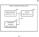
- Fig. 9 shows an alignment parameter estimation system 900 according to various embodiments.
- the alignment parameter estimation system 900 may include a measurement data determination circuit 902, a velocity determination circuit 904, and a misalignment parameters determination circuit 906.
- the measurement data determination circuit 902 may be configured to determine measurement data using a radar sensor, the measurement data comprising a range-rate measurement, an azimuth measurement, and an elevation measurement.
- the radar sensor may be a part of the measurement data determination circuit 902, or may be provided external to the measurement data determination circuit 902.
- the velocity determination circuit 904 may be configured to determine a velocity of the radar sensor using a velocity sensor.
- the velocity sensor may be a part of the velocity determination circuit 904, or may be provided external to the velocity determination circuit 904.
- the misalignment parameters determination circuit 906 may be configured to determine misalignment parameters of the radar sensor based on the measurement data and the velocity, the misalignment parameters comprising an azimuth misalignment, an elevation misalignment, and a roll misalignment
- the measurement data determination circuit 902, the velocity determination circuit 904, and the misalignment parameters determination circuit 906 may be coupled with each other, e.g. via an electrical connection 908, such as e.g. a cable or a computer bus or via any other suitable electrical connection to exchange electrical signals.
- an electrical connection 908 such as e.g. a cable or a computer bus or via any other suitable electrical connection to exchange electrical signals.
- a “circuit” may be understood as any kind of a logic implementing entity, which may be special purpose circuitry or a processor executing a program stored in a memory, firmware, or any combination thereof.
- Fig. 10 shows a computer system 1000 with a plurality of computer hardware components configured to carry out steps of a computer implemented method for determining alignment parameters of a radar sensor according to various embodiments.
- the computer system 1000 may include a processor 1002, a memory 1004, and a non-transitory data storage 1006.
- a radar sensor 1008 and/or a velocity sensor 1010 may be provided as part of the computer system 1000 (like illustrated in Fig. 10 ), or may be provided external to the computer system 1000.
- the processor 1002 may carry out instructions provided in the memory 1004.
- the non-transitory data storage 1006 may store a computer program, including the instructions that may be transferred to the memory 1004 and then executed by the processor 1002.
- the radar sensor 1008 may be used for determining measurement data as described above.
- the velocity sensor 1010 may be used to determine the velocity as described above.
- the processor 1002, the memory 1004, and the non-transitory data storage 1006 may be coupled with each other, e.g. via an electrical connection 1012, such as e.g. a cable or a computer bus or via any other suitable electrical connection to exchange electrical signals.
- the radar sensor 1008 and/or the velocity sensor 1010 may be coupled to the computer system 1000, for example via an external interface, or may be provided as parts of the computer system (in other words: internal to the computer system, for example coupled via the electrical connection 1012).
- Coupled or “connection” are intended to include a direct “coupling” (for example via a physical link) or direct “connection” as well as an indirect “coupling” or indirect “connection” (for example via a logical link), respectively.
Landscapes
- Engineering & Computer Science (AREA)
- Radar, Positioning & Navigation (AREA)
- Remote Sensing (AREA)
- Physics & Mathematics (AREA)
- Computer Networks & Wireless Communication (AREA)
- General Physics & Mathematics (AREA)
- Electromagnetism (AREA)
- Radar Systems Or Details Thereof (AREA)
Abstract
Description
- The present disclosure relates to methods and systems for determining alignment parameters of a radar sensor.
- Radar-sensors, for example in automotive applications, need to be aligned with the chassis of a host-vehicle so that the location of detected objects is accurately known. Alignment procedures performed when the host-vehicle is assembled are not able to compensate for pitch or elevation errors caused by heavy cargo and yaw, azimuth or roll errors caused by miss-alignment of the wheels or chassis of the host-vehicle which may cause 'crabbing' or 'dog-tracking' by the host-vehicle while traveling.
- Accordingly, there is a need to provide for reliable determination of alignment parameters.
- The present disclosure provides a computer implemented method, a radar system, a computer system, a vehicle, and a non-transitory computer readable medium according to the independent claims. Embodiments are given in the subclaims, the description and the drawings.
- In one aspect, the present disclosure is directed at a computer implemented method for determining alignment parameters of a radar sensor, the method comprising the following steps performed (in other words: carried out) by computer hardware components: determining measurement data using the radar sensor, the measurement data comprising a range-rate measurement, an azimuth measurement, and an elevation measurement; determining a velocity (in other words: speed) of the radar sensor using a velocity sensor; and determining the misalignment parameters based on the measurement data and the velocity, the misalignment parameters comprising an azimuth misalignment, an elevation misalignment, and a roll misalignment.
- According to various embodiments, misalignment parameters may be determined by comparing a velocity determined by a velocity sensor (which may be independent from the radar sensor) and velocity information which is determined based on radar measurement data.
- The measurements data may be related to the radar sensor, for example to a radar sensor mounted on a vehicle (for example at least partially autonomously driving vehicle, for example car), for example on the chassis of the vehicle. The velocity sensor may be external to the radar sensor; for example, the velocity sensor may be the velocity sensor of a vehicle, for example based on odometry measurements, gyroscope measurements, and/or acceleration measurements.
- According to another aspect, the misalignment parameters further comprise a speed-scaling error.
- It has been found that provided a three-axial-auto-alignment with speed-scaling-error estimation improves the detection quality of radar sensors.
- According to another aspect, the computer implemented method further comprises the following step carried out by the computer hardware components: determining system parameters, the system parameters comprising at least one of a desired azimuth mounting angle, a desired elevation mounting angle, and a desired roll mounting angle; wherein the misalignment parameters are determined further based on the system parameters.
- The system parameters may be set by the manufacturer of the system (for example vehicle) on which the radar sensor is provided. The system parameters may describe or define how the radar sensor is provided (for example mounted) in the vehicle.
- According to another aspect, the measurement data is related to a plurality of objects external to the radar sensor. For example, measurement results related to at least three objects may be provided. For example, measurement results related to at least four objects may be provided. For example, measurement results related to at least five objects may be provided. The number of objects may be chosen so that the system for determining the misalignment parameters is at least not under-determined, for example so that the system is over-determined (i.e. more measurement results may be available than unknown misalignment parameters are to be determined; this may allow for implicit correction of measurement inaccuracies or measurement errors, for example by using regression methods to determine the misalignment parameters).
- The objects may be provided outside a vehicle in which the radar sensor is provided.
- According to another aspect, the plurality of objects are stationary. Thus, it may be considered known that the velocity determined by the velocity sensor is identical to the (relative) velocity of the stationary objects (relative to the radar sensor). This may be used for determining the misalignment parameters by determining the misalignment parameters so that the velocity determined based on the radar measurements is in agreement with the velocity determined by the velocity sensor (for example so that the difference between the velocity determined based on the radar measurements is in agreement with the velocity determined by the velocity sensor is minimized).
- According to another aspect, the misalignment parameters are determined based on an iterative method.
- A closed-form solution to the determination of the misalignment parameters may not be available, or may be numerically instable. An iterative method may be used, starting from an initial estimate (or guess), for example with all misalignment parameters set to a default value (for example 0). The estimate values may be iteratively updated. The misalignment parameters may already be of reasonable accuracy after one iteration. Depending on the resources like time and computational power, more than one iteration may be performed. The iterations may continue until a pre-determined stop criterion is reached, for example a maximum time available for the determination of the misalignment parameters, or a pre-determined accuracy of the misalignment parameters (which may for example be determined based on how much (for example absolutely or relatively) the estimates for the misalignment parameters change from one iteration to the next iteration).
- According to another aspect, the misalignment parameters are determined based on an optimization method.
- The optimization method may optimize the misalignment parameters so that the difference between the velocity measured by the velocity sensor and the velocity which is determined based on the measurement data is minimized. The optimization method may determine the misalignment parameters from an overdetermined system (wherein more measurements, for example related to a plurality of objects, are available than would be required for a closed form determination of the misalignment parameters). The optimization method may use the Jacobian matrix, including partial derivatives of the modeled output with respect to the misalignment parameters.
- According to another aspect, the misalignment parameters are determined based on a non-linear least squares regression method. According to another aspect, the misalignment parameters are determined based on an non-linear total least squares regression method.
- According to another aspect, the misalignment parameters are determined based on filtering. For example, the misalignment parameters that have been determined based on the optimization or regression method may be subject to filtering, for example Kalman filtering, to further improve the misalignment parameters.
- With the method according to various embodiments, the overall performance of the alignment may be improved, which may have a positive impact on the performance of further radar processing.
- In another aspect, the present disclosure is directed at a computer implemented method for determining corrected measurement data, the method comprising the following steps carried out by computer hardware components: determining measurement data using a radar sensor; correcting the measurement data to obtain the corrected measurement data based on misalignment parameters determined according to the computer-implemented method described herein.
- With the corrected measurement data, improved detection results may be achieved.
- Based on the misalignment parameters, the control of the radar sensor (for example the area in which the radar sensor is to determine measurements) may be adjusted (for example to the desired area or desired field of view).
- In another aspect, the present disclosure is directed at a computer system, said computer system comprising a plurality of computer hardware components configured to carry out several or all steps of the computer implemented method described herein. The computer system can be part of a vehicle.
- The computer system may comprise a plurality of computer hardware components (for example a processor, for example processing unit or processing network, at least one memory, for example memory unit or memory network, and at least one non-transitory data storage). It will be understood that further computer hardware components may be provided and used for carrying out steps of the computer implemented method in the computer system. The non-transitory data storage and/or the memory unit may comprise a computer program for instructing the computer to perform several or all steps or aspects of the computer implemented method described herein, for example using the processing unit and the at least one memory unit.
- In another aspect, the present disclosure is directed at a radar system comprising a radar sensor for which the misalignment parameters are determined according to the computer implemented method described herein.
- In another aspect, the present disclosure is directed at a vehicle comprising the radar system described herein.
- In another aspect, the present disclosure is directed at a non-transitory computer readable medium comprising instructions for carrying out several or all steps or aspects of the computer implemented method described herein. The computer readable medium may be configured as: an optical medium, such as a compact disc (CD) or a digital versatile disk (DVD); a magnetic medium, such as a hard disk drive (HDD); a solid state drive (SSD); a read only memory (ROM), such as a flash memory; or the like. Furthermore, the computer readable medium may be configured as a data storage that is accessible via a data connection, such as an internet connection. The computer readable medium may, for example, be an online data repository or a cloud storage.
- The present disclosure is also directed at a computer program for instructing a computer to perform several or all steps or aspects of the computer implemented method described herein.
- Exemplary embodiments and functions of the present disclosure are described herein in conjunction with the following drawings, showing schematically:
- Fig. 1A
- an illustration of a radar field-of-view when misaligned in azimuth and elevation;
- Fig. 1B
- an illustration of a three-dimensional misalignment in azimuth, elevation, and roll;
- Fig. 2
- a flow diagram illustrating an overview of methods for determining alignment parameters according to various embodiments;
- Fig. 3
- an illustration of a radar field-of-view after introduction of roll misalignment;
- Fig. 4
- an illustration of a radar field-of-view and a compensated field-of-view according to various embodiments;
- Fig. 5
- a diagram illustrating azimuth alignment error distribution according to various embodiments;
- Fig. 6
- a diagram illustrating elevation alignment error distribution according to various embodiments;
- Fig. 7
- a diagram illustrating roll alignment error distribution according to various embodiments;
- Fig. 8
- a flow diagram illustrating a method for determining alignment parameters of a radar sensor according to various embodiments;
- Fig. 9
- an alignment parameter estimation system according to various embodiments; and
- Fig. 10
- a computer system with a plurality of computer hardware components configured to carry out steps of a computer implemented method for determining alignment parameters of a radar sensor according to various embodiments.
- Radar alignment is a process of determining the angular misalignment of radar facing direction. Correction of those mounting errors may be crucial for proper operation of radar based tracking methods and most of the feature functions that operate on detections or tracked objects provided by a radar sensor. Two main classes of methods/approaches aimed at solving misalignment problem are:
- 1) static alignment methods, which may also be called factory alignment, due to the reason that they require specialized equipment to perform the calibration process; most commonly used static methods use corner reflectors, Doppler generators, or steel plates;
- 2) dynamic alignment methods, which may also be called auto-alignment since they may not require any external (additional) equipment (devices) for the process. The radar sensor is correcting its facing angles based on observation of the environment while the car is moving (i.e. driving).
-
Fig. 1A andFig. 1B showsillustrations -
Fig. 1A shows anillustration 100 of a radar field-of-view 110 when misaligned in azimuth (along a horizontal line 102) and elevation (along avertical split line 104 at the front of the vehicle, which corresponds to 0 deg). The ideal (or desired or assumed) facingangle 106 is different from the real (or actual) facingangle 108, so that amisalignment 112 is present. -
Fig. 1B shows anillustration 150 of a three-dimensional misalignment in azimuth (α), elevation (β), and roll (γ). Coordinates axis are illustrated in the vehicle coordinate system (VCS), i.e.X VCS 152,Y VCS 154, andZ VCS 156. Theground plane 158 is illustrated. The radar sensor may be mounted aboveground plane 158 at the origin of the vehicle coordinate system. The desired boresight direction for perfect alignment would coincide withX VCS 152. However, the actualboresight direction 160 is different fromX VCS 152 due to the misalignment, and the difference between the actualboresight direction 160 andX VCS 152 may be described by the three-dimensional misalignment in azimuth (α), elevation (β), and roll (γ). Due to the misalignment, the desired FOV 162 (field of view) may be different from theactual FOV 164. However, the desiredFOV 162 may be obtained by correction based on misalignment parameters based on theactual FOV 164. - To calculate the misalignment in case of a misalignment in azimuth and elevation (disregarding a possible misalignment in roll), the range rate equation of stationary detections may be used. It may be derived from the projection of the negative vehicle velocity vector to the vector of distance, which forms the equation below:

- ṙ is the range rate (Doppler velocity of stationary detection);
- VX is the longitudinal velocity of the vehicle (which may be a vector facing forward from vehicle, parallel to the ground plane; VX may be the length of that vector);
- VY is the lateral velocity of the vehicle (which may be a vector facing left side of vehicle, parallel to the ground plane; VY may be the length of that vector);
- VZ is the vertical velocity of the vehicle (which may be a vector facing ground, perpendicular to the ground plane; VZ may be the length of that vector);
- αVCS is the azimuth measurement of detection aligned to vehicle coordinate system (wherein the 0 [deg] angle may be defined as facing the same direction as the front of the vehicle on which the radar sensor is mounted); and
- βVCS is the elevation measurement of detection aligned to vehicle coordinate system.
- VCS aligned measurement angles may be decomposed into sensor mounting angles, sensor detection measurement angles as well as sensor mounting misalignment angles:


- αSCS is the azimuth measurement of detection in sensor coordinate system (SCS);
- αB is the desired azimuth mounting angle;
- αM is the desired azimuth misalignment;
- βSCS is the elevation measurement of detection in sensor coordinate system;
- βB is the desired elevation mounting angle; and
- βM is the elevation misalignment.
- Further expanding the equation with speed correction factor Vc (which may also be referred to as (vehicle) speed-scaling-error or speed compensation factor) leads to:


- VXm is the measured longitudinal velocity of vehicle;
- VYm is the measured lateral velocity of vehicle;
- VZm is the measured vertical velocity of the vehicle; and
- Vc is the speed-scaling-error.
- An equation may be created which may be used to find unknown parameters (B), based on measurements (X), known constants (C) and equation result (Y) as follows:

- Various methods, such as iterative non-linear least squares regression or error-in-variables methods, may be used to determine the unknown parameters. The parameters found by these methods may then further be refined by filtering in time methods such as Kalman filter.
-
Fig. 2 shows a flow diagram 200 illustrating an overview of methods for determining alignment parameters according to various embodiments (either not taking into account a misalignment in roll angle, or taking into account a misalignment in roll angle, like will be described in more detail below). At 202, data acquisition may be carried out, which may include stationary detections, vehicle velocities, and radar information. At 204, regression may be carried out, for example including estimation of azimuth misalignment, estimation of elevation misalignment, estimation of roll misalignment (as will be described in more detail below), and estimation of speed-scaling error. At 206, filtering (for example using a Kalman filter) may be provided. - Significant roll misalignment angle of the sensor (desired sensor roll is usually zero) can greatly impact the azimuth and elevation measurements, because it reduces radar field of view as shown below.
- Roll angle misalignment may influence the azimuth-elevation misalignment calculation itself.
-
Fig. 3 shows anillustration 300 of a radar field-of-view after introduction of roll misalignment, similar to what is shown inFig. 1A (wherein inFig. 1A no roll misalignment is illustrated).Illustration 302 in the left portion ofFig. 3 shows an illustration from the ground perspective, andillustration 304 in the right portion ofFig. 3 shows an illustration from the sensor perspective. - As can be seen from
Fig. 3 , if the roll misalignment would not be taken into account, the azimuth misalignment may be taken as 0 (zero) or close to 0, and the elevation misalignment may be estimated to be greater than the correct value of the elevation misalignment, due to the fact that the ideal facing angle is exactly below the reported facing angle as seen by the radar sensor. This may result in finding wrong misalignment parameters, for example zero azimuth misalignment and too high elevation misalignment value. - The impact of the roll angle misalignment may be almost unobservable for small angles (for example less than 1 [deg]), and may be growing exponentially with the roll, introducing highest error at the corners of field-of-view. At a 30 [deg] radar roll (i.e. a misalignment of the radar sensor in roll angle of 30 deg), as is illustrated in
Fig. 3 andFig. 4 , the error is reducing the field of view of radar by half (the sensor may observe ground in near vicinity of front of the vehicle, and the sky above on the opposite side of FOV; however, both the ground and the sky regions are irrelevant from the active safety methods perspective). At the same time, a significant part of important information about objects located approximately 0.5 m above the ground is missed. Furthermore, an undetected roll angle misalignment may make the azimuth and elevation misalignment angles unreliable. For example, an object at 60 deg azimuth and 5 deg elevation under influence of 5 deg sensor roll misalignment will be reported at azimuth 60.20 deg and -0.2484 deg elevation. - The radar roll angle misalignment may be determined by extending the range rate equation, which makes estimation of the roll angle possible. The equation may further improve estimation of yaw and pitch angle misalignments. After the estimation of 3 angle misalignments (yaw, pitch, roll) the measured detections may be corrected to represent detections in vehicle coordinate system or in extreme misalignment the estimated value may trigger an alert which will stop the execution of further radar functions.
- The range rate equation (1) may be used together with equations (2) and (3), which may be extended with the roll angle influence, what leads to following equations:


- α'SCS is the azimuth measurement corrected by roll misalignment in sensor coordinate system;
- β'SCS is the elevation measurement corrected by roll misalignment in sensor coordinate system;
- γM is the roll misalignment; and
- γB is the roll ideal mounting position (which may usually be 0 deg or 180 deg).
- Therefore, α'SCS and β'SCS may be visualized as detections with the same distance from radar center of view (0, 0), but rotated (aligned) w.r.t. horizon line (assuming desired roll mounting angle of 0 [deg]), forming a 'compensated field of view' as shown on
Fig. 4 . -
Fig. 4 shows anillustration 400 of a radar field-of-view 110 and a compensated field-of-view 402 according to various embodiments. Various portions ofFig. 4 are similar or identical to portions ofFig. 1A , so that the same reference signs may be used and duplicate description may be omitted. - After substitution of eqns. (8) and (9) (α' and β'SCS ) to eqns. (2) (3) for αSCS and βSCS, respectively, the following equations may be obtained:


- This change modifies the general model in equation (7) to:

- The general form of this model can be derived from range rate equation (1)

- Eq. (13) can be simplified with the assumption of the vehicle moving only in forward direction (VYm and VZm equal to 0) and elevation and roll desired mounting angles 0 [deg], to get the following form:

- Equation (16) may be used to compose (create) a overdetermined system of equations which can be solved by various methods to find parameters of interest i.e. misalignment angles and speed compensation factor. In an example, equation (14) may be used as a model for non-linear least square regression. For example, the model may be iterative, which means that the method will iterate over the same dataset containing data from one time instance to converge to the solution of non-linear equation in multiple steps defined by linearization of the model around its operating point:

- The matrix equation (17) can be transformed to:

- ΔB is the update of parameters value in a single iteration (single step in a solution space);
- J are the partial derivatives of model function over the parameters (which may be referred to as Jacobian matrix); and
- ΔY is the difference between the measured output of the system and model output:

- The Jacobian matrix may take the following form:


- The non-linear regression model described by equations (18) to (24) may be solved after assuming initial values of parameters:

- Therefore, equation (26) may update model parameter values with values at i-th iteration:

- Bi may converge to real speed-scaling-error and misalignment angles at infinite number of iterations (or as iteration number approaches infinity):

- The method according to various embodiments provides alignment parameters also for the roll axis, which accurately describes the physical model.
-
Fig. 5 ,Fig. 6 andFig. 7 illustrate the performance of methods according to various embodiments over simulated data for random (nonzero) misalignments of all mounting angles i.e. azimuth, elevation and roll. The following simulation parameters were used: - number of test cases (samples): 500 000 (same inputs for each method);
- misalignments (azimuth, elevation and roll): pseudorandom values drawn from uniform distribution on interval [-5:5] deg;
- azimuth boresight pseudorandom value drawn from uniform distribution on interval [-180; 180] deg;
- vehicle moving in a straight line (XVCS direction);
- minimum vehicle speed: 11 m/s;
- number of detections: 64;
- azimuth Gaussian zero mean noise: Standard deviation 0.3 deg;
- elevation Gaussian zero mean noise:
Standard deviation 1 deg ; - range rate Gaussian zero mean noise: Standard deviation 0.03 m/s;
- vehicle velocity Gaussian zero mean noise in 3-axis : Standard deviation 0.2 m/s.
- The result of only a single iteration (first iteration) of each of compared method is shown in each of
Fig. 5 ,Fig. 6 , andFig. 7 . NL-LS in the method name may stand for non-linear least squares regression used to find the solution, and NL-TLS may stand for non-linear total least squares regression. A 2-axial alignment with no roll estimation is shown for comparison purposes. -
Fig. 5 shows a diagram 500 illustrating azimuth alignment error distribution according to various embodiments. The deviation angle is illustrated over ahorizontal axis 502. The numbers of samples is illustrated over avertical axis 504. The results for a 2 axial alignment are illustrated bycurve 506. The results for a 3 axial alignment NL-LS method according to various embodiments are illustrated bycurve 508. The results for a 3 axial alignment NL-TLS method according to various embodiments are illustrated bycurve 510. -
Fig. 6 shows a diagram 600 illustrating elevation alignment error distribution according to various embodiments. The deviation angle is illustrated over ahorizontal axis 602. The numbers of samples is illustrated over avertical axis 604. The results for a 2 axial alignment are illustrated bycurve 606. The results for a 3 axial alignment NL-LS method according to various embodiments are illustrated bycurve 608. The results for a 3 axial alignment NL-TLS method according to various embodiments are illustrated bycurve 610. -
Fig. 7 shows a diagram 700 illustrating roll alignment error distribution according to various embodiments. The deviation angle is illustrated over ahorizontal axis 702. The numbers of samples is illustrated over avertical axis 704. The results for a 3 axial alignment NL-LS method according to various embodiments are illustrated bycurve 706. The results for a 3 axial alignment NL-TLS method according to various embodiments are illustrated bycurve 708. - As shown in
Fig. 5 andFig. 6 , even one-time-instance-based (non-iterative) results are much better in case of azimuth and elevation misalignment estimation with 3-axial alignment compared to a 2-axial alignment. -
Fig. 7 shows the error distribution of roll angle alignment, in thiscase 2 axial alignment is not available as it doesn't return the roll angle estimation. -
Fig. 8 shows a flow diagram 800 illustrating a method for determining alignment parameters of a radar sensor according to various embodiments. At 802, measurement data may be determined using the radar sensor, wherein the measurement data may include a range-rate measurement, an azimuth measurement, and an elevation measurement. At 804, a velocity of the radar sensor may be determined using a velocity sensor. At 806, the misalignment parameters may be determined based on the measurement data and the velocity, wherein the misalignment parameters may include an azimuth misalignment, an elevation misalignment, and a roll misalignment. - According to various embodiments, the misalignment parameters may further include a speed-scaling error.
- According to various embodiments, system parameters may be determined, wherein the system parameters may include at least one of a desired azimuth mounting angle, a desired elevation mounting angle, and a desired roll mounting angle. The misalignment parameters may be determined further based on the system parameters.
- According to various embodiments, the measurement data may be related to a plurality of objects external to the radar sensor.
- According to various embodiments, the plurality of objects may be stationary.
- According to various embodiments, the misalignment parameters may be determined based on an iterative method.
- According to various embodiments, the misalignment parameters may be determined based on an optimization method.
- According to various embodiments, the misalignment parameters may be determined based on a non-linear least squares regression method.
- According to various embodiments, the misalignment parameters may be determined based on an non-linear total least squares regression method. According to various embodiments, the misalignment parameters may be determined based on filtering.
- Each of the
steps -
Fig. 9 shows an alignmentparameter estimation system 900 according to various embodiments. The alignmentparameter estimation system 900 may include a measurementdata determination circuit 902, avelocity determination circuit 904, and a misalignmentparameters determination circuit 906. - The measurement
data determination circuit 902 may be configured to determine measurement data using a radar sensor, the measurement data comprising a range-rate measurement, an azimuth measurement, and an elevation measurement. The radar sensor may be a part of the measurementdata determination circuit 902, or may be provided external to the measurementdata determination circuit 902. - The
velocity determination circuit 904 may be configured to determine a velocity of the radar sensor using a velocity sensor. The velocity sensor may be a part of thevelocity determination circuit 904, or may be provided external to thevelocity determination circuit 904. - The misalignment
parameters determination circuit 906 may be configured to determine misalignment parameters of the radar sensor based on the measurement data and the velocity, the misalignment parameters comprising an azimuth misalignment, an elevation misalignment, and a roll misalignment - The measurement
data determination circuit 902, thevelocity determination circuit 904, and the misalignmentparameters determination circuit 906 may be coupled with each other, e.g. via anelectrical connection 908, such as e.g. a cable or a computer bus or via any other suitable electrical connection to exchange electrical signals. - A "circuit" may be understood as any kind of a logic implementing entity, which may be special purpose circuitry or a processor executing a program stored in a memory, firmware, or any combination thereof.
-
Fig. 10 shows acomputer system 1000 with a plurality of computer hardware components configured to carry out steps of a computer implemented method for determining alignment parameters of a radar sensor according to various embodiments. Thecomputer system 1000 may include aprocessor 1002, amemory 1004, and anon-transitory data storage 1006. Aradar sensor 1008 and/or avelocity sensor 1010 may be provided as part of the computer system 1000 (like illustrated inFig. 10 ), or may be provided external to thecomputer system 1000. - The
processor 1002 may carry out instructions provided in thememory 1004. Thenon-transitory data storage 1006 may store a computer program, including the instructions that may be transferred to thememory 1004 and then executed by theprocessor 1002. Theradar sensor 1008 may be used for determining measurement data as described above. Thevelocity sensor 1010 may be used to determine the velocity as described above. - The
processor 1002, thememory 1004, and thenon-transitory data storage 1006 may be coupled with each other, e.g. via anelectrical connection 1012, such as e.g. a cable or a computer bus or via any other suitable electrical connection to exchange electrical signals. Theradar sensor 1008 and/or thevelocity sensor 1010 may be coupled to thecomputer system 1000, for example via an external interface, or may be provided as parts of the computer system (in other words: internal to the computer system, for example coupled via the electrical connection 1012). - The terms "coupling" or "connection" are intended to include a direct "coupling" (for example via a physical link) or direct "connection" as well as an indirect "coupling" or indirect "connection" (for example via a logical link), respectively.
- It will be understood that what has been described for one of the methods above may analogously hold true for the alignment
parameter estimation system 900 and/or for thecomputer system 1000. -
- 100
- illustration of a radar field-of-view when misaligned in azimuth and elevation
- 102
- horizontal line
- 104
- vertical split line
- 106
- ideal facing angle
- 108
- real facing angle
- 110
- radar field-of-view
- 112
- misalignment
- 150
- illustration of a three-dimensional misalignment in azimuth, elevation, and roll
- 152
- x axis
- 154
- y axis
- 156
- z axis
- 158
- ground plane
- 160
- actual boresight direction
- 162
- desired field of view
- 164
- actual field of view
- 200
- flow diagram illustrating an overview of methods for determining alignment parameters according to various embodiments
- 202
- data acquisition
- 204
- regression
- 206
- filtering
- 300
- illustration of a radar field-of-view after introduction of roll misalignment
- 302
- illustration from the ground perspective
- 304
- illustration from the sensor perspective
- 400
- illustration of a radar field-of-view and a compensated field-of-view according to various embodiments
- 402
- compensated field-of-view
- 500
- diagram illustrating azimuth alignment error distribution according to various embodiments
- 502
- horizontal axis
- 504
- vertical axis
- 506
- curve illustrating results for a 2 axial alignment
- 508
- curve illustrating results for a 3 axial alignment NL-LS method according to various embodiments
- 510
- curve illustrating results for a 3 axial alignment NL-TLS method according to various embodiments
- 600
- diagram illustrating elevation alignment error distribution according to various embodiments
- 602
- horizontal axis
- 604
- vertical axis
- 606
- curve illustrating results for a 2 axial alignment
- 608
- curve illustrating results for a 3 axial alignment NL-LS method according to various embodiments
- 610
- curve illustrating results for a 3 axial alignment NL-TLS method according to various embodiments
- 700
- diagram illustrating roll alignment error distribution according to various embodiments
- 702
- horizontal axis
- 704
- vertical axis
- 706
- curve illustrating results for a 3 axial alignment NL-LS method according to various embodiments
- 708
- curve illustrating results for a 3 axial alignment NL-TLS method according to various embodiments
- 800
- flow diagram illustrating a method for determining alignment parameters of a radar sensor according to various embodiments
- 802
- step of determining measurement data using the radar sensor
- 804
- step of determining a velocity of the radar sensor using a velocity sensor
- 806
- step of determining the misalignment parameters based on the measurement data and the velocity
- 900
- alignment parameter estimation system according to various embodiments
- 902
- measurement data determination circuit
- 904
- velocity determination circuit
- 906
- misalignment parameters determination circuit
- 908
- connection
- 1000
- computer system according to various embodiments
- 1002
- processor
- 1004
- memory
- 1006
- non-transitory data storage
- 1008
- radar sensor
- 1010
- velocity sensor
- 1012
- connection
Claims (15)
- Computer implemented method for determining alignment parameters of a radar sensor,
the method comprising the following steps carried out by computer hardware components:- determining measurement data using the radar sensor, the measurement data comprising a range-rate measurement, an azimuth measurement, and an elevation measurement;- determining a velocity of the radar sensor using a velocity sensor; and- determining the misalignment parameters based on the measurement data and the velocity, the misalignment parameters comprising an azimuth misalignment, an elevation misalignment, and a roll misalignment. - The computer implemented method of claim 1,
wherein the misalignment parameters further comprise a speed-scaling error. - The computer implemented method of at least one of claims 1 or 2, further comprising the following step carried out by the computer hardware components:determining system parameters, the system parameters comprising at least one of a desired azimuth mounting angle, a desired elevation mounting angle, and a desired roll mounting angle;wherein the misalignment parameters are determined further based on the system parameters.
- The computer implemented method of at least one of claims 1 to 3, wherein the measurement data is related to a plurality of objects external to the radar sensor.
- The computer implemented method of claim 4,
wherein the plurality of objects are stationary. - The computer implemented method of at least one of claims 1 to 5, wherein the misalignment parameters are determined based on an iterative method.
- The computer implemented method of at least one of claims 1 to 6, wherein the misalignment parameters are determined based on an optimization method.
- The computer implemented method of at least one of claims 1 to 7, wherein the misalignment parameters are determined based on a non-linear least squares regression method.
- The computer implemented method of at least one of claims 1 to 8, wherein the misalignment parameters are determined based on an non-linear total least squares regression method.
- The computer implemented method of at least one of claims 1 to 9, wherein the misalignment parameters are determined based on filtering.
- Computer implemented method for determining corrected measurement data,
the method comprising the following steps carried out by computer hardware components:determining measurement data using a radar sensor;correcting the measurement data to obtain the corrected measurement data based on misalignment parameters determined according to the computer-implemented method of at least one of claims 1 to 10. - Computer system, the computer system comprising a plurality of computer hardware components configured to carry out steps of the computer implemented method of at least one of claims 1 to 11.
- A radar system comprising a radar sensor for which the misalignment parameters are determined according to the computer implemented method of at least one of claims 1 to 11.
- A vehicle comprising the radar system of claim 13.
- Non-transitory computer readable medium comprising instructions for carrying out the computer implemented method of at least one of claims 1 to 11.
Priority Applications (4)
| Application Number | Priority Date | Filing Date | Title |
|---|---|---|---|
| EP20172809.4A EP3907521A1 (en) | 2020-05-04 | 2020-05-04 | Methods and systems for determining alignment parameters of a radar sensor |
| EP21166327.3A EP3907522A3 (en) | 2020-05-04 | 2021-03-31 | Methods and systems for determining alignment parameters of a radar sensor |
| US17/306,856 US20210341599A1 (en) | 2020-05-04 | 2021-05-03 | Methods and Systems for Determining Alignment Parameters of a Radar Sensor |
| CN202110488715.6A CN113608182B (en) | 2020-05-04 | 2021-05-06 | Method and system for determining alignment parameters of a radar sensor |
Applications Claiming Priority (1)
| Application Number | Priority Date | Filing Date | Title |
|---|---|---|---|
| EP20172809.4A EP3907521A1 (en) | 2020-05-04 | 2020-05-04 | Methods and systems for determining alignment parameters of a radar sensor |
Publications (1)
| Publication Number | Publication Date |
|---|---|
| EP3907521A1 true EP3907521A1 (en) | 2021-11-10 |
Family
ID=70553794
Family Applications (2)
| Application Number | Title | Priority Date | Filing Date |
|---|---|---|---|
| EP20172809.4A Withdrawn EP3907521A1 (en) | 2020-05-04 | 2020-05-04 | Methods and systems for determining alignment parameters of a radar sensor |
| EP21166327.3A Withdrawn EP3907522A3 (en) | 2020-05-04 | 2021-03-31 | Methods and systems for determining alignment parameters of a radar sensor |
Family Applications After (1)
| Application Number | Title | Priority Date | Filing Date |
|---|---|---|---|
| EP21166327.3A Withdrawn EP3907522A3 (en) | 2020-05-04 | 2021-03-31 | Methods and systems for determining alignment parameters of a radar sensor |
Country Status (3)
| Country | Link |
|---|---|
| US (1) | US20210341599A1 (en) |
| EP (2) | EP3907521A1 (en) |
| CN (1) | CN113608182B (en) |
Cited By (1)
| Publication number | Priority date | Publication date | Assignee | Title |
|---|---|---|---|---|
| EP4249942A1 (en) * | 2022-03-23 | 2023-09-27 | Veoneer Sweden AB | Alignment detection for a vehicle radar transceiver |
Families Citing this family (9)
| Publication number | Priority date | Publication date | Assignee | Title |
|---|---|---|---|---|
| TWI761203B (en) * | 2021-05-06 | 2022-04-11 | 同致電子企業股份有限公司 | Vehicle radar auxiliary fixture, vehicle radar installation method and vehicle radar test method |
| US12601596B2 (en) * | 2021-10-07 | 2026-04-14 | L3Harris Technologies, Inc. | Estimation of target location and sensor misalignment angles |
| EP4187276A1 (en) * | 2021-11-30 | 2023-05-31 | Aptiv Technologies Limited | Method and system for estimating a radar calibration matrix |
| WO2023141848A1 (en) * | 2022-01-27 | 2023-08-03 | Qualcomm Incorporated | Boresight direction alignment based on reference signal transmission and reception |
| DE102022204007A1 (en) * | 2022-04-26 | 2023-10-26 | Robert Bosch Gesellschaft mit beschränkter Haftung | Method for calibrating a radar sensor |
| EP4293381B1 (en) * | 2022-06-15 | 2025-09-24 | Aptiv Technologies AG | Method for estimating a mounting position of a radar sensor |
| US12578429B1 (en) * | 2023-07-31 | 2026-03-17 | Zoox, Inc. | Radar calibration validation and/or recalibration |
| EP4703760A1 (en) * | 2024-08-30 | 2026-03-04 | Robert Bosch GmbH | Detecting a sensor mounting roll angle of an environment detection sensor |
| US20260072131A1 (en) * | 2024-09-12 | 2026-03-12 | Torc Robotics, Inc. | Systems and methods for rapid radar misalignment monitoring |
Citations (3)
| Publication number | Priority date | Publication date | Assignee | Title |
|---|---|---|---|---|
| DE102014223461A1 (en) * | 2014-11-18 | 2016-05-19 | Robert Bosch Gmbh | Method and device for determining misalignment angles of a radar system |
| EP3279683A1 (en) * | 2016-07-22 | 2018-02-07 | Delphi Technologies, Inc. | Automated vehicle radar system with auto-alignment for azimuth, elevation, and vehicle speed-scaling-error |
| WO2019042523A1 (en) * | 2017-08-28 | 2019-03-07 | HELLA GmbH & Co. KGaA | Method for operation of a radar system |
Family Cites Families (6)
| Publication number | Priority date | Publication date | Assignee | Title |
|---|---|---|---|---|
| US3943508A (en) * | 1971-03-25 | 1976-03-09 | Hughes Aircraft Company | Electronic roll compensation system for a radar antenna |
| RU2410711C2 (en) * | 2008-12-16 | 2011-01-27 | Открытое акционерное общество "Ульяновский механический завод" | Method of measuring coordinates of mobile radar set target |
| DE102013209530A1 (en) * | 2013-05-23 | 2014-11-27 | Robert Bosch Gmbh | DETERMINATION OF AN ELVAGE DEJUSTING ANGLE OF A RADAR SENSOR OF A MOTOR VEHICLE |
| US9568592B1 (en) * | 2014-11-04 | 2017-02-14 | Google Inc. | Automotive sensor alignment with external IMU tool |
| CN117607841A (en) * | 2017-08-11 | 2024-02-27 | 祖克斯有限公司 | Calibration and positioning of vehicle sensors |
| EP3575827B1 (en) * | 2018-06-01 | 2024-07-31 | Aptiv Technologies AG | Method for robust estimation of the velocity of a target using a host vehicle |
-
2020
- 2020-05-04 EP EP20172809.4A patent/EP3907521A1/en not_active Withdrawn
-
2021
- 2021-03-31 EP EP21166327.3A patent/EP3907522A3/en not_active Withdrawn
- 2021-05-03 US US17/306,856 patent/US20210341599A1/en not_active Abandoned
- 2021-05-06 CN CN202110488715.6A patent/CN113608182B/en active Active
Patent Citations (3)
| Publication number | Priority date | Publication date | Assignee | Title |
|---|---|---|---|---|
| DE102014223461A1 (en) * | 2014-11-18 | 2016-05-19 | Robert Bosch Gmbh | Method and device for determining misalignment angles of a radar system |
| EP3279683A1 (en) * | 2016-07-22 | 2018-02-07 | Delphi Technologies, Inc. | Automated vehicle radar system with auto-alignment for azimuth, elevation, and vehicle speed-scaling-error |
| WO2019042523A1 (en) * | 2017-08-28 | 2019-03-07 | HELLA GmbH & Co. KGaA | Method for operation of a radar system |
Cited By (1)
| Publication number | Priority date | Publication date | Assignee | Title |
|---|---|---|---|---|
| EP4249942A1 (en) * | 2022-03-23 | 2023-09-27 | Veoneer Sweden AB | Alignment detection for a vehicle radar transceiver |
Also Published As
| Publication number | Publication date |
|---|---|
| US20210341599A1 (en) | 2021-11-04 |
| EP3907522A3 (en) | 2022-02-23 |
| CN113608182A (en) | 2021-11-05 |
| CN113608182B (en) | 2024-11-12 |
| EP3907522A2 (en) | 2021-11-10 |
Similar Documents
| Publication | Publication Date | Title |
|---|---|---|
| EP3907522A2 (en) | Methods and systems for determining alignment parameters of a radar sensor | |
| Huang et al. | Observability-based consistent EKF estimators for multi-robot cooperative localization | |
| CN115790603B (en) | Unmanned aerial vehicle dynamic target estimation method used in information refusing environment | |
| Wang et al. | An adaptive UKF based SLAM method for unmanned underwater vehicle | |
| US9846229B1 (en) | Radar velocity determination using direction of arrival measurements | |
| US9513130B1 (en) | Variable environment high integrity registration transformation system and related method | |
| CN107643519A (en) | Automatic Vehicle Radar System with Automatic Alignment for Azimuth, Elevation and Vehicle Velocity Scale Errors | |
| CN111751857A (en) | Vehicle pose estimation method, device, storage medium and system | |
| Guangcai et al. | An iterative Doppler velocity log error calibration algorithm based on Newton optimization | |
| JP2024507381A (en) | Method for determining at least one system state using Kalman filter | |
| CN114217283A (en) | Doppler radar static fusion smoothing structure-changing filtering method and device | |
| Song et al. | Gps-vio fusion with online rotational calibration | |
| CN113252029A (en) | Astronomical navigation attitude transfer method based on optical gyroscope measurement information | |
| Wu et al. | A self-adaptive unscented Kalman filtering for underwater gravity aided navigation | |
| Kwon et al. | Radar velocity measurements aided navigation system for UAVs | |
| CN116992213B (en) | An anti-interference antenna nulling and widening method assisted by inertial navigation information | |
| US20200271421A1 (en) | Robust angle only nine state target state estimator (tse) | |
| US20230408721A1 (en) | Method and device for analyzing 3d target maneuver using line array sensor | |
| Chu et al. | Performance comparison of tight and loose INS-Camera integration | |
| Kitsukawa et al. | Robustness Evaluation of Vehicle Localization in 3D Map Using Convergence of Scan Matching | |
| Huang et al. | Research on sensor fusion-based calibration and real-time point cloud mapping methods for laser lidar and IMU | |
| JP2019086386A (en) | Azimuth error function acquiring device, method and program | |
| CN119492380B (en) | A multi-robot consistent collaborative positioning method and system based on transformation | |
| CN115931007B (en) | A method for calibrating SINS/DVL installation error angles based on optimized alignment | |
| CN117804448B (en) | Autonomous system positioning method, device, computer equipment and storage medium |
Legal Events
| Date | Code | Title | Description |
|---|---|---|---|
| PUAI | Public reference made under article 153(3) epc to a published international application that has entered the european phase |
Free format text: ORIGINAL CODE: 0009012 |
|
| STAA | Information on the status of an ep patent application or granted ep patent |
Free format text: STATUS: THE APPLICATION HAS BEEN PUBLISHED |
|
| AK | Designated contracting states |
Kind code of ref document: A1 Designated state(s): AL AT BE BG CH CY CZ DE DK EE ES FI FR GB GR HR HU IE IS IT LI LT LU LV MC MK MT NL NO PL PT RO RS SE SI SK SM TR |
|
| B565 | Issuance of search results under rule 164(2) epc |
Effective date: 20201023 |
|
| STAA | Information on the status of an ep patent application or granted ep patent |
Free format text: STATUS: REQUEST FOR EXAMINATION WAS MADE |
|
| 17P | Request for examination filed |
Effective date: 20220506 |
|
| RBV | Designated contracting states (corrected) |
Designated state(s): AL AT BE BG CH CY CZ DE DK EE ES FI FR GB GR HR HU IE IS IT LI LT LU LV MC MK MT NL NO PL PT RO RS SE SI SK SM TR |
|
| RAP3 | Party data changed (applicant data changed or rights of an application transferred) |
Owner name: APTIV TECHNOLOGIES LIMITED |
|
| STAA | Information on the status of an ep patent application or granted ep patent |
Free format text: STATUS: EXAMINATION IS IN PROGRESS |
|
| 17Q | First examination report despatched |
Effective date: 20240111 |
|
| RAP1 | Party data changed (applicant data changed or rights of an application transferred) |
Owner name: APTIV TECHNOLOGIES AG |
|
| STAA | Information on the status of an ep patent application or granted ep patent |
Free format text: STATUS: THE APPLICATION HAS BEEN WITHDRAWN |
|
| 18W | Application withdrawn |
Effective date: 20240508 |