EP3907465A1 - Electronic apparatus control method performed through lid angle calculation, electronic apparatus thereof and software product - Google Patents
Electronic apparatus control method performed through lid angle calculation, electronic apparatus thereof and software product Download PDFInfo
- Publication number
- EP3907465A1 EP3907465A1 EP21171687.3A EP21171687A EP3907465A1 EP 3907465 A1 EP3907465 A1 EP 3907465A1 EP 21171687 A EP21171687 A EP 21171687A EP 3907465 A1 EP3907465 A1 EP 3907465A1
- Authority
- EP
- European Patent Office
- Prior art keywords
- lid
- angle
- value
- reliability
- signals
- Prior art date
- Legal status (The legal status is an assumption and is not a legal conclusion. Google has not performed a legal analysis and makes no representation as to the accuracy of the status listed.)
- Granted
Links
Images


Classifications
-
- G—PHYSICS
- G01—MEASURING; TESTING
- G01B—MEASURING LENGTH, THICKNESS OR SIMILAR LINEAR DIMENSIONS; MEASURING ANGLES; MEASURING AREAS; MEASURING IRREGULARITIES OF SURFACES OR CONTOURS
- G01B7/00—Measuring arrangements characterised by the use of electric or magnetic techniques
- G01B7/30—Measuring arrangements characterised by the use of electric or magnetic techniques for measuring angles or tapers; for testing the alignment of axes
-
- G—PHYSICS
- G01—MEASURING; TESTING
- G01D—MEASURING NOT SPECIALLY ADAPTED FOR A SPECIFIC VARIABLE; ARRANGEMENTS FOR MEASURING TWO OR MORE VARIABLES NOT COVERED IN A SINGLE OTHER SUBCLASS; TARIFF METERING APPARATUS; MEASURING OR TESTING NOT OTHERWISE PROVIDED FOR
- G01D18/00—Testing or calibrating apparatus or arrangements provided for in groups G01D1/00 - G01D15/00
-
- G—PHYSICS
- G01—MEASURING; TESTING
- G01D—MEASURING NOT SPECIALLY ADAPTED FOR A SPECIFIC VARIABLE; ARRANGEMENTS FOR MEASURING TWO OR MORE VARIABLES NOT COVERED IN A SINGLE OTHER SUBCLASS; TARIFF METERING APPARATUS; MEASURING OR TESTING NOT OTHERWISE PROVIDED FOR
- G01D5/00—Mechanical means for transferring the output of a sensing member; Means for converting the output of a sensing member to another variable where the form or nature of the sensing member does not constrain the means for converting; Transducers not specially adapted for a specific variable
- G01D5/12—Mechanical means for transferring the output of a sensing member; Means for converting the output of a sensing member to another variable where the form or nature of the sensing member does not constrain the means for converting; Transducers not specially adapted for a specific variable using electric or magnetic means
- G01D5/14—Mechanical means for transferring the output of a sensing member; Means for converting the output of a sensing member to another variable where the form or nature of the sensing member does not constrain the means for converting; Transducers not specially adapted for a specific variable using electric or magnetic means influencing the magnitude of a current or voltage
- G01D5/142—Mechanical means for transferring the output of a sensing member; Means for converting the output of a sensing member to another variable where the form or nature of the sensing member does not constrain the means for converting; Transducers not specially adapted for a specific variable using electric or magnetic means influencing the magnitude of a current or voltage using Hall-effect devices
-
- G—PHYSICS
- G01—MEASURING; TESTING
- G01D—MEASURING NOT SPECIALLY ADAPTED FOR A SPECIFIC VARIABLE; ARRANGEMENTS FOR MEASURING TWO OR MORE VARIABLES NOT COVERED IN A SINGLE OTHER SUBCLASS; TARIFF METERING APPARATUS; MEASURING OR TESTING NOT OTHERWISE PROVIDED FOR
- G01D5/00—Mechanical means for transferring the output of a sensing member; Means for converting the output of a sensing member to another variable where the form or nature of the sensing member does not constrain the means for converting; Transducers not specially adapted for a specific variable
- G01D5/12—Mechanical means for transferring the output of a sensing member; Means for converting the output of a sensing member to another variable where the form or nature of the sensing member does not constrain the means for converting; Transducers not specially adapted for a specific variable using electric or magnetic means
- G01D5/14—Mechanical means for transferring the output of a sensing member; Means for converting the output of a sensing member to another variable where the form or nature of the sensing member does not constrain the means for converting; Transducers not specially adapted for a specific variable using electric or magnetic means influencing the magnitude of a current or voltage
- G01D5/16—Mechanical means for transferring the output of a sensing member; Means for converting the output of a sensing member to another variable where the form or nature of the sensing member does not constrain the means for converting; Transducers not specially adapted for a specific variable using electric or magnetic means influencing the magnitude of a current or voltage by varying resistance
-
- G—PHYSICS
- G05—CONTROLLING; REGULATING
- G05B—CONTROL OR REGULATING SYSTEMS IN GENERAL; FUNCTIONAL ELEMENTS OF SUCH SYSTEMS; MONITORING OR TESTING ARRANGEMENTS FOR SUCH SYSTEMS OR ELEMENTS
- G05B17/00—Systems involving the use of models or simulators of said systems
- G05B17/02—Systems involving the use of models or simulators of said systems electric
-
- G—PHYSICS
- G06—COMPUTING OR CALCULATING; COUNTING
- G06F—ELECTRIC DIGITAL DATA PROCESSING
- G06F1/00—Details not covered by groups G06F3/00 - G06F13/00 and G06F21/00
- G06F1/16—Constructional details or arrangements
- G06F1/1613—Constructional details or arrangements for portable computers
- G06F1/1615—Constructional details or arrangements for portable computers with several enclosures having relative motions, each enclosure supporting at least one I/O or computing function
- G06F1/1616—Constructional details or arrangements for portable computers with several enclosures having relative motions, each enclosure supporting at least one I/O or computing function with folding flat displays, e.g. laptop computers or notebooks having a clamshell configuration, with body parts pivoting to an open position around an axis parallel to the plane they define in closed position
Definitions
- the present invention relates to an electronic apparatus control method performed via calculation of an angle of lid opening, to an electronic apparatus thereof and to a software product.
- a portable device 1 of a known type is typically formed by two functional blocks 2, 4, where the functional block 2 accommodates a screen 2a and the functional block 4 accommodates a keypad 4a and the control unit and memory 4b, 4c.
- the functional blocks 2 and 4 are coupled together by a pivot 6, configured for enabling a rotary movement of the functional block 2 with respect to the functional block 4.
- An angle ⁇ LID known as opening angle or by the term “lid angle" is formed between the functional block 2 (i.e., at the screen 2a) and the functional block 4 (i.e., at the keypad 4a).
- the angle ⁇ LID is formed between respective surfaces of the functional block 2 and of the functional block 4.
- the angle ⁇ LID is equal to 0° when the surface of the functional block 4 is parallel to and directly facing the surface of the functional block 2; and is equal to 360° when the surface of the functional block 4 is parallel to the surface of the functional block 2 but oriented in the opposite direction.
- the measurement of the angle ⁇ LID enables, for example, adaptation or modification of a user interface displayed by the screen 2a in order to improve user experience of the portable device 1.
- Known solutions for detecting the angle ⁇ LID envisage the use of an accelerometer mounted on the functional block 2 and of an accelerometer mounted on the functional block 4. Said accelerometers supply data indicating the direction of the force of gravity with respect to respective systems of co-ordinates centred on the accelerometers themselves, thus making it possible to identify a position of the functional block 2 with respect to the functional block 4.
- this solution being based exclusively upon the information deriving from the force gravity, does not make it possible to provide indications useful for all the possible orientations and arrangements in space of the portable device 1. In fact, this solution does not enable a reliable measurement if the portable device 1 is oriented with the pivot 6 parallel to the direction of the force of gravity (i.e., vertical position, or book-like position, of the portable device 1).
- the accelerometers are subject to environmental vibrational stimuli that may cause the measurement to be imprecise or wrong.
- the measurement of the angle ⁇ LID is unreliable when the portable device is moving or else is subjected to external vibrations, for example when a person who is carrying the portable device is walking or is travelling in a means of transport.
- a filter e.g., a lowpass filter
- each functional block further includes a respective gyroscope.
- Gyroscopes are used in order to improve the reactivity of the measurement of the angle ⁇ LID and to enable, through a data-fusion approach, said measurement to be made even when the portable device is rotated in the vertical position.
- the aim of the present invention is to provide an electronic apparatus control method performed through lid angle calculation, an electronic apparatus thereof and a software product that overcome the drawbacks of the prior art.
- an electronic apparatus control method performed through lid angle calculation, an electronic apparatus thereof and a software product are provided, as defined in the attached claims.
- an electronic apparatus in particular, a portable device 10 is illustrated in a triaxial cartesian reference system XYZ defined by the axes X, Y and Z.
- a vector g or acceleration vector g
- a vector B which represents the Earth's magnetic field vector (hereinafter, magnetic field B or magnetic-field vector B)
- magnetic field B or magnetic-field vector B
- the magnetic field B acts in a plane YZ defined by the axes Y, Z, and in particular forms with the axis Y an inclination angle ⁇ , for example equal to about 45°, and forms with the acceleration vector a respective angle, for example equal to the angle of inclination ⁇ .
- the device 10 is of a portable type (in particular, a notebook) and is here represented in an operative condition of open device.
- the portable device 10 includes a lid portion 12 and a base portion 14, mechanically coupled to each other by means of a hinge 15, which enables rotation of the lid portion 12 with respect to the base portion 14, forming a rotation constraint about a rotation axis R (or axis R), in Figure 2 represented by way of example parallel to the axis X.
- the base portion 14 comprises at least one interface device 16 (e.g., a keypad and/or a trackpad), extending at a surface 14a of the base portion 14.
- the lid portion 12 comprises a display region 18 (e.g., a screen or monitor), extending at a surface 12a of the lid portion 12.
- the surfaces 12a, 14a face one another.
- the lid portion 12 accommodates (e.g., integrates within it) a first magnetometer 20 configured for detecting and/or calculating the orientation, along respective sensing axes x 1 , y 1 , z 1 , of the lid portion 12 with respect to the magnetic field B; and the base portion 14 accommodates (e.g., integrates within it) a second magnetometer 22, configured for detecting and/or calculating the orientation, along respective sensing axes x 2 , y 2 , z 2 , of the base portion 14 with respect to the magnetic field B.
- the first and second magnetometers 20, 22 are configured for generating a first magnetic-field signal (hereinafter, first signal B 1 ) and, respectively, a second magnetic-field signal (hereinafter, second signal B 2 ).
- first and second magnetometers 20, 22 are configured to detect a change of orientation of the portable device 10 by means of measurements of the magnetic field B.
- the first and second magnetometers 20, 22 are, for example, magnetometers obtained with MEMS technology (e.g., MEMS magnetometers based upon AMR, Anisotropic MagnetoResistance, technology).
- the first signal B 1 is indicative of the components of the magnetic field B along the sensing axes x 1 , y 1 , z 1
- the second signal B 2 is indicative of the components of the magnetic field B along the sensing axes x 2 , y 2 , z 2 .
- the axis R of the hinge 15 is always parallel to the sensing axes x 1 , x 2 in any operative condition (lid portion 12 closed or open) and for any orientation of the device 10 in the triaxial reference system XYZ.
- the portable device 10 further comprises a processing unit that includes a microcontroller or control unit 27 and a memory 28, coupled together.
- the control unit 27 and/or the memory 28 are moreover operatively coupled to the first and second magnetometers 20, 22 for receiving therefrom the respective signals B 1 , B 2 , generated according to operation in itself known of magnetometers.
- the signals B 1 , B 2 received at input from the control unit 27 are processed as better described hereinafter with reference to Figure 5 .
- the first and second magnetometers 20, 22 are configured to detect the variation of a mutual orientation between the lid portion 12 and the base portion 14 (for example, due to opening and closing, with respect to the base portion 14, of the lid portion 12 turning about the axis R due to the hinge 15).
- the first and second magnetometers 20, 22 are used for determining an opening angle ⁇ LID , supplementary to an angle between the sensing axis y 1 and the sensing axis y 2 of the respective first and second magnetometers 20, 22.
- the opening angle ⁇ LID is therefore correlated to the angle existing between the surface 12a of the lid portion 12 and the surface 14a of the base portion 14 and is also known as "lid angle".
- the value of the lid angle ⁇ LID with a use mode of the portable device 10 (e.g., a lid angle ⁇ LID having a value of about 130° suggests a laptop-use mode, whereas a lid angle ⁇ LID having a value of 360° suggests a tablet-use mode. It is therefore possible to adapt the graphic interface represented in the display region 18 to the type of operating mode, or else adapt other operating parameters of the portable device 10, for example enabling a touchscreen function when the tablet-use mode is detected, or vary other parameters still, such as switching-on/switching-off of the display region 18 or of the portable device 10 if the value the lid angle ⁇ LID is greater/less than a certain threshold.
- FIG 3 illustrates, in lateral view in the plane YZ, the portable device 10 of Figure 2 , where the lid portion 12 is represented in three possible operative conditions S1-S3: lid portion 12 closed on the base portion 14, defining a lid angle ⁇ LID of zero value (S1); lid portion 12 defining a lid angle ⁇ LID of 90° with respect to the base portion 14 (S2); and lid portion 12 defining a lid angle ⁇ LID of 180° with respect to the base portion 14 (S3).
- S1-S3 lid portion 12 closed on the base portion 14, defining a lid angle ⁇ LID of zero value (S1); lid portion 12 defining a lid angle ⁇ LID of 90° with respect to the base portion 14 (S2); and lid portion 12 defining a lid angle ⁇ LID of 180° with respect to the base portion 14 (S3).
- the lid angle ⁇ LID is the relative angle between the sensing axis y 1 and the sensing axis y 2 of the magnetometers 20 and 22 (in detail, between the positive semi-axis of the axis y 1 and the negative semi-axis of the axis y 2 ) and, since it has been assumed that said sensing axes y 1 , y 2 are parallel to the surfaces 12a, 14a of the lid portion 12 and the base portion 14, the lid angle ⁇ LID is also the relative angle between the surfaces 12a, 14a of the lid portions 12 and the base portion 14. In other words, the lid angle ⁇ LID coincides with the opening angle (or lid angle) of the lid portion 12 with respect to the base portion 14.
- the same angular quantity may likewise be defined between the axes z 1 and z 2 (in detail, between the positive semi-axis of the axis z 1 and the negative semi-axis of the axis z 2 ), which are always normal to the surfaces 12a, 14a.
- the first magnetometer 20 detects a variation of the components of the magnetic field B along the axes z 1 and y 1 , and this makes it possible to determine the fact that the lid angle ⁇ LID increases (whereas the opposite is true, in the passage from the condition S2 to the condition S1, or from the condition S3 to the condition S2).
- the magnetic field B is given, in the operative condition S1, by first values detected on the axes y 1 , z 1 and, in the operative condition S2, by second values detected on the axes y 1 , z 1 , said second values being different from the first values.
- Gz 1 is the component of the magnetic field B detected by the first magnetometer 20 along the sensing axis z 1
- Gy 1 is the component of the magnetic field B detected by the first magnetometer 20 along the sensing axis y 1
- Gz 2 is the component of the magnetic field B detected by the second magnetometer 22 along the sensing axis z 2
- Gy 2 is the component of the magnetic field B detected by the second magnetometer 22 along the sensing axis y 2
- the value ⁇ LID_MAG measured via the magnetometers 20, 22 represents a relative orientation (i.e., an orientation that is not absolute in space) between the lid portion 12 and the base portion 14.
- Figure 4A shows a mode of use of the portable device 10 where the portable device 10 is oriented with the axis R parallel to the magnetic-field vector B.
- the portable device 10 is oriented with the axis R parallel to the magnetic-field vector B.
- passage into the operative conditions S1-S2-S3 does not cause a variation of the component of magnetic field B along the sensing axes z 1 , z 2 , and y 1 , y 2 of the first and second magnetometers 20, 22, since the components of the magnetic field B along the axes referred to are always zero or substantially zero (i.e., the values Gz 1 , Gz 2 , Gy 1 , Gy 2 of Eq. (1) are approximately equal to zero). Consequently, in this situation the value ⁇ LID_MAG cannot be calculated accurately.
- the components Gx 1 and Gx 2 In operative conditions where the sensing axes x 1 and x 2 are parallel to the magnetic field B and the sensing axes y 1 and y 2 are perpendicular to the magnetic field B ( Figure 4A ), the components Gx 1 and Gx 2 have a maximum value, and the components Gy 1 and Gy 2 have a minimum value; instead, in operative conditions where the sensing axes x 1 and x 2 are perpendicular to the magnetic field B and the sensing axes y 1 and y 2 are parallel to the magnetic field B, the components Gx 1 and Gx 2 have a minimum value and the components Gy 1 and Gy 2 have a maximum value (the minimum and maximum values depend upon the type of inertial sensor used and are defined by the manufacturer).
- the reliability of the calculation of the value ⁇ LID_MAG is therefore correlated to a first reliability angle ⁇ 1 , which represents the measurement of the reliability angle ⁇ made via the magnetometers 20, 22.
- the first angle ⁇ a therefore varies between 0° and 90°.
- a second angle ⁇ b is calculated via the second magnetometer 22.
- the first reliability angle ⁇ 1 is correlated to the first angle ⁇ a and/or the second angle ⁇ b .
- the first reliability angle ⁇ 1 is equal to the first angle ⁇ a or to the second angle ⁇ b ; according to a different aspect of the present invention, the first reliability angle ⁇ 1 is equal to an average (alternatively, a weighted average) of the first and second angles ⁇ a , ⁇ b .
- the measurement of the value ⁇ LID_MAG is considered reliable; and if the first reliability angle ⁇ 1 is smaller than or equal to the threshold angle ⁇ th , the measurement of the value ⁇ LID_MAG is considered unreliable.
- the threshold angle ⁇ th is equal to approximately 20°.
- the measurement of the value ⁇ LID_MAG is considered reliable only if both of the angles ⁇ a , ⁇ b are greater than the threshold angle ⁇ th .
- control unit 27 with the possible support of the memory 28, is configured for executing the operations illustrated in Figure 5 and described hereinafter.
- Figure 5 is a schematic illustration of functional blocks implemented, via software and in an iterative way, by the control unit 27 and memory 28.
- the control unit 27 acquires the first signal B 1 and the second signal B 2 via the first magnetometer 20 and the second magnetometer 22, respectively.
- the first signal B 1 represents (e.g., comprises) the components Gx 1 , Gy 1 , and Gz 1 (in particular, Gx 1 (t), Gy 1 (t), and Gz 1 (t))
- the second signal B 2 represents (e.g., comprises) the components Gx 2 , Gy 2 , and Gz 2 (in particular, Gx 2 (t), Gy 2 (t), and Gz 2 (t)).
- a calibration block 49 receives at input the components Gx 1 (t), Gy 1 (t), Gz 1 (t), Gx 2 (t), Gy 2 (t), and Gz 2 (t), and returns at output a first calibration value J 1 , indicative of the possible presence of magnetic interference and magnetic distortion of the magnetometers 20, 22.
- the first calibration value J 1 is correlated to a calibration reliability of the magnetometers 20, 22.
- the calibration block 49 is illustrated in detail in Figure 5A , with reference to the case where the first calibration value J 1 assumes a binary value.
- the first calibration value J 1 is initialised at 0 (unreliable calibration).
- the control unit 27 acquires, via the magnetometers 20, 22, calibration data D 1 (e.g., equal to the signals B 1 , B 2 , or else comprising a result of processing of the signals B 1 , B 2 acquired in a first calibration interval).
- the calibration parameters P cal include a soft iron matrix (SI) and a hard-iron vector (HI), and are calculated in a way in itself known.
- calibrated data D 2 are generated on the basis of the calibration data D 1 and of the calibration parameters P cal .
- the calibrated data D 2 are the result of processing of the calibration data D 1 performed via the calibration parameters P cal .
- a condition regarding calibration of the magnetometers 20, 22 is evaluated. In particular, it is determined whether it is necessary to carry out a calibration of the magnetometers 20, 22. This calibration enables compensation of electromagnetic effects to which the magnetometers 20, 22 are subjected, due to factors such as variations in time of magnetization of components arranged in the proximity to the magnetometers themselves or the presence of ferromagnetic material.
- the control unit 27 compares the calibrated data D 2 with an expected range (e.g., defined between approximately 0.25 gauss and approximately 0.75 gauss), correlated to an expected intensity of the Earth's magnetic field.
- of the calibrated data D 2 satisfies, at the current iteration t, a first relation (e.g., it is comprised in said expected range and, for instance, is comprised between approximately 0.25 gauss and approximately 0.75 gauss, extremes included) the condition on the calibration of the magnetometers 20, 22 yields a negative result, and it is not necessary to carry out a new calibration; if the Euclidean norm
- said first relation e.g., it is not comprised in the expected range, and for instance it is less than 0.25 gauss or greater than 0.
- the portable device 10 is rotated freely in three-dimensional space by the operator, and simultaneously the control unit 27 acquires the signals B 1 , B 2 during a second calibration interval, via the magnetometers 20, 22.
- the signals B 1 , B 2 acquired during the second calibration interval are processed according to known techniques for generating new calibration parameters P cal , which replace the previous calibration parameters P cal .
- the first calibration value J 1 is set at 0.
- the first calibration value J 1 is set at 1, to indicate that the calibration is reliable.
- a condition regarding magnetic interference e.g., interference caused by electromagnetic sources set in the proximity of the portable device 10.
- the calibrated data D 2 are evaluated in time to determine whether the magnetometers 20, 22 are subjected to magnetic interference.
- the second relation is satisfied if the variance of the Euclidean norm
- the first calibration value J 1 is set at 0 in a block 49f following block 49e in the case of output "YES", to indicate that the calibration is unreliable.
- the first calibration value J 1 which, if it is equal to 0, indicates that the calibration is unreliable (and therefore also the measurement of the value ⁇ LID_MAG will not be reliable), whereas, if it is equal to 1, indicates that the calibration is reliable (and therefore the measurement of the value ⁇ LID_MAG could be reliable, as described hereinafter).
- the base portion 14 lies in a horizontal plane XY, resting on an ideally flat surface. Since the magnetometers 20, 22 are in a fixed position and the orientation of the respective sensing axes is known, it is possible to calculate, via the control unit 27, the value ⁇ LID_MAG (in particular, ⁇ LID_MAG (t)) of the lid angle ⁇ LID (in particular, ⁇ LID (t)) as expressed by Eq. (1).
- a first calculation block 50 implements Eq.
- a first reliability block 52 receives at input, from the first and second magnetometers 20, 22, the components Gx 1 (t), Gy 1 (t), Gz 1 (t), Gx 2 (t), Gy 2 (t), and Gz 2 (t) and implements Eq. (2) for calculating the first reliability angle ⁇ 1 (in particular, ⁇ 1 (t)), as described previously.
- the first reliability angle ⁇ 1 (t) is then compared, as discussed previously, with the threshold angle ⁇ th to establish the reliability of the calculation of the value ⁇ LID_MAG (t).
- the first reliability value K 1 will therefore vary between a minimum value and a maximum value the more the components Gx 1 (t) and Gx 2 (t) decrease and the components Gy 1 (t), Gy 2 (t), Gz 1 (t) and Gz 2 (t) increase; the minimum reliability value K 1 may be the zero value, whereas the maximum reliability value K 1 is chosen between 0 (excluded) and 1 according to the considerations that will be made in what follows with reference to block 56. Moreover, the first reliability value K 1 is correlated to the first calibration value J 1 .
- a determination block 53 receives at input the first reliability value K 1 from the first reliability block 52 and the value ⁇ LID_MAG (t) from the first calculation block 50, and determines the lid angle ⁇ LID (t).
- the lid angle ⁇ LID (t) is set equal to a predefined value; for example, it is set equal to 0°.
- the lid angle ⁇ LID (t) is calculated, on the basis of the value ⁇ LID_MAG (t) and as a function of the first reliability value K 1 , via a dynamic lowpass filter or a complementary filter.
- the lid angle ⁇ LID (t) is set equal to a predefined value; for example, it is set equal to 0°.
- ⁇ LID (t) is, for example set at a value equal to ⁇ LID_MAG (t), or else at a predefined value.
- ⁇ LID t 1 ⁇ J 1 ⁇ K 1 ⁇ ⁇ LID t ⁇ 1 + J 1 ⁇ K 1 ⁇ ⁇ LID_MAG t rad
- Figure 6 shows the portable device 10 in a different embodiment, analogous to the one illustrated in Figure 2 .
- the lid portion 12 moreover accommodates (e.g., integrates within it) a first accelerometer 30, configured for detecting and/or calculating values of acceleration of the lid portion 12 along respective sensing axes x 3 , y 3 , z 3 , parallel to the sensing axes x 1 , y 1 , z 1 , respectively, of the first magnetometer 20; and the base portion 14 moreover accommodates (e.g., integrates within it) a second accelerometer 32, configured for detecting and/or calculating values of acceleration of the base portion 14 along respective sensing axes x 4 , y 4 , z 4 , parallel to the sensing axes x 2 , y 2 , z 2 , respectively, of the second magnetometer 22.
- a first accelerometer 30 configured for detecting and/or calculating values of acceleration of the lid portion 12 along respective sensing axes x 3 , y 3 , z 3 , parallel to the sensing axes x 1 ,
- the axis R of the hinge 15 is always parallel to the sensing axes x 1 , x 2 , x 3 , x 4 in any operative condition (lid portion 12 closed or open) and for any orientation of the device 10 in the triaxial reference system XYZ.
- the first and second accelerometers 30, 32 are operatively coupled to the control unit 27 and/or to the memory 28 and are configured to detect a movement and/or change of orientation of the portable device 10 by measuring accelerations.
- the first and second accelerometers 30, 32 are, for example, accelerometers obtained with MEMS technology.
- the first accelerometer 30 detects a variation of the component of the acceleration of gravity g along the axes z 3 and y 3 and determines that the angle ⁇ LID has increased (the reverse applies in the passage from the condition S2 to the condition S1, or from the condition S3 to the condition S2) .
- the acceleration of gravity g is given, in the operative condition S1, exclusively by the value detected along the axis z 3 and, in the operative condition S2, exclusively by the value detected along the axis y 3 .
- both of the axes y 3 and z 3 yield the same value of acceleration.
- the sensing axis z 3 is parallel to the gravity acceleration vector g (the projection of the gravity acceleration vector g on the axis z 3 is maximum), in the operative condition S2, the sensing axis z 3 is orthogonal to the gravity acceleration vector g (the projection of the gravity acceleration vector g on the axis z 3 is minimum), and in the operative condition S3, the sensing axis z 3 is parallel to the gravity acceleration vector g, but has an opposite orientation as compared to the operative condition S1 (the projection of the gravity acceleration vector g on the axis z 3 is maximum, but with opposite sign).
- the reliability of the calculation of the value ⁇ LID_ACC is therefore correlated to a second reliability angle ⁇ 2 , which represents the measurement of the reliability angle ⁇ made via the accelerometers 30, 32.
- the third angle ⁇ c therefore varies between 0° and 90°.
- a fourth angle ⁇ d is calculated via the second accelerometer 32.
- the second reliability angle ⁇ 2 is correlated to the third angle ⁇ c and/or to the fourth angle ⁇ d , as has been described previously with reference to the first reliability angle ⁇ 1 .
- the measurement of the value ⁇ LID_ACC is considered reliable, and if the second reliability angle ⁇ 2 is smaller than or equal to said further threshold angle, the measurement of the value ⁇ LID_ACC is considered unreliable.
- the measurement of the value ⁇ LID_ACC is considered reliable only if both of the angles ⁇ c , ⁇ d are greater than the further threshold angle.
- the measurements obtained by the first and second accelerometers 30, 32 are fused with the measurements obtained by the first and second magnetometers 20, 22; for example, the measurements obtained from the first and second accelerometers 30, 32 are more weighted (and, accordingly, the measurements obtained from the first and second magnetometers 20, 22 are less weighted), the smaller the angle between the axis R and the magnetic field B (i.e., the more closely the condition of Figure 4A is approached).
- the reliability of the measurement of the angle ⁇ LID is guaranteed both when the axis R is parallel to the magnetic field B and when it is parallel to the acceleration of gravity g (i.e., parallel to the axis Z). Since the magnetic field B and the acceleration of gravity g are mutually orthogonal, the measurement of the angle ⁇ LID , made as described more fully hereinafter, is always reliable.
- control unit 27 with the optional support of the memory 28, is moreover operatively connected to the accelerometers 30, 32 and is configured for executing the operations illustrated in Figure 7 and described hereinafter.
- Figure 7 is a schematic illustration of functional blocks analogous to the ones illustrated in Figure 5 .
- a second calculation block 55 is represented in Figure 7 and configured for receiving at input the values of acceleration (comprising, in detail, the components Ay 3 , Az 3 , Ay 4 and Az 4 ) detected by the first and second accelerometers 30, 32, and calculating the value ⁇ LID_ACC of the lid angle ⁇ LID on the basis of Eq. (4) .
- a second reliability block 54 is moreover present, receiving at input, from the first and second accelerometers 30, 32, the components Ax 3 (t), Ay 3 (t), Az 3 (t), Ax 4 (t), Ay 4 (t), and Az 4 (t), and implementing Eq. (5) for calculating the second reliability angle ⁇ 2 (in particular, ⁇ 2 (t)).
- the second reliability angle ⁇ 2 (t) is then compared with the further threshold angle to establish the reliability of the calculation of the value ⁇ LID_ACC (t).
- the second reliability block 54 therefore generates at output a second reliability value K 2 analogous to the first reliability value K 1 .
- a first fusion block 56 replacing in Figure 7 the determination block 53 of Figure 5 , has the function of generating a final value, deemed reliable, of the lid angle ⁇ LID on the basis of the first reliability value K 1 and/or the second reliability value K 2 .
- the first fusion block 56 receives at input the first reliability value K 1 and/or the second reliability value K 2 and both of the values ⁇ LID_MAG ⁇ LID_ACC calculated, respectively, according to Eq. (1) (i.e., using just the signals of the magnetometers 20, 22) and according to Eq. (4) (i.e., using just the signals of the accelerometers 30, 32).
- a further calibration block receives at input the components Ax 3 (t), Ay 3 (t), Az 3 (t), Ax 4 (t), Ay 4 (t), and Az 4 (t), verifies whether said components are calibrated and returns at output calibrated components (said components at output being equal to the components at input if the components at input are calibrated, and being different from the components at input if the components at input are not calibrated).
- the lid portion 12 moreover accommodates (e.g., integrates within it) a first gyroscope 40, configured for detecting and/or calculating an orientation and rotation of the lid portion 12 along, and about, sensing axes l 1 , m 1 , n 1 that are parallel, respectively, to the sensing axes x 1 , y 1 , z 1 of the first magnetometer 20; and the base portion 14 moreover accommodates (e.g., integrates within it) a second gyroscope 42, configured for detecting and/or calculating an orientation and rotation of the base portion 14 along, and about, sensing axes l 2 , m 2 , n 2 that are parallel, respectively, to the sensing axes x 2 , y 2 , z 2 of the second magnetometer 22.
- a first gyroscope 40 configured for detecting and/or calculating an orientation and rotation of the lid portion 12 along, and about, sensing axes l 1 ,
- the axis R of the hinge 15 is always parallel to the sensing axes x 1 , x 2 , l 1 , l 2 in any operative condition (lid portion 12 closed or open) and for any orientation of the device 10 in the triaxial reference system XYZ.
- the first and second gyroscopes 40, 42 are operatively coupled to the control unit 27 and/or to the memory 28 and are configured to detect a movement of the portable device 10 by measuring angular velocities.
- the first and second gyroscopes 40, 42 are, for example, gyroscopes obtained with MEMS technology.
- the measurements obtained from the first and second gyroscopes 40, 42 are fused with the measurements obtained from the first and second magnetometers 20, 22; for example, the measurements obtained from the first and second gyroscopes 40, 42 are more weighted (and, accordingly, the measurements obtained from the first and second magnetometers 20, 22 are less weighted), the more the angle between the axis R and the magnetic field B decreases (i.e., the more closely the condition of Figure 4A is approached). In this way, the reliability of the measurement of the angle ⁇ LID is guaranteed even when the axis R is parallel to the magnetic field B.
- a complementary filter is used (but it is also possible to use other types of filtering, e.g., Kalman filtering), and the magnetometric component is rejected or attenuated, the more the angle between the axis R and the magnetic field B decreases.
- the magnetometric component specifically has the function of correcting the drift of the angle calculated by the gyroscopes 40, 42.
- ⁇ ⁇ ⁇ x 2 ⁇ ⁇ x 1 ⁇ dt rad
- ⁇ x1 is the angular velocity measured by the first gyroscope 40 with respect to the sensing axis l 1
- ⁇ x2 is the angular velocity measured by the second gyroscope 42 with respect to the sensing axis l 2 .
- the value dt represents the time that has elapsed between the instant t - 1 and the instant t (data-sampling or data-acquisition time of the gyroscopes 40, 42, which in turn may depend upon the updating time of the system, for example comprised between 25 Hz and 200 Hz). For instance, if sampling of the output of the gyroscopes 40, 42 occurs at 100 Hz, the parameter dt is equal to 0.01 s.
- control unit 27 with the possible support of the memory 28, is moreover operatively connected to the gyroscopes 40, 42 and is configured for executing the operations illustrated in Figure 9 and described hereinafter.
- Figure 9 is a schematic illustration of functional blocks analogous to the ones represented in Figure 5 .
- Figure 9 further comprises a third calculation block 58 configured for receiving at input the values of angular velocity ⁇ x1 , ⁇ x2 detected by the first and second gyroscopes 40, 42, and calculating a value ⁇ LID_GYR of the lid angle ⁇ LID on the basis of Eq. (8) referred to in what follows.
- the third calculation block 58 includes a sub-block 58a configured for calculating (at the instant t) the variation ⁇ ⁇ of the value ⁇ LID (t) of the lid angle ⁇ LID with respect to the value ⁇ LID (t - 1) previously measured (at the previous instant t - 1), according to Eq. (7) provided above.
- the third calculation block 58 includes a further sub-block 58b, configured for receiving the variation value ⁇ ⁇ and the last value ⁇ LID (t - 1) of the lid angle ⁇ LID calculated and deemed reliable (e.g., generated at output from a second fusion block 60, described hereinafter), and updating in a recursive way said last value ⁇ LID (t - 1) of the lid angle ⁇ LID using the variation value ⁇ ⁇ .
- the second fusion block 60 has the function of generating a final value, deemed reliable, of the lid angle ⁇ LID on the basis of the first reliability value K 1 calculated by the first reliability block 52.
- the second fusion block 60 receives at input both of the values ⁇ LID_MAG (t), ⁇ LID_GYR (t) calculated according to Eq. (1) (i.e., using just the signals of the magnetometers 20, 22) and, respectively, according to Eq. (8) (i.e., by updating the value ⁇ LID (t - 1) with the variation ⁇ ⁇ obtained via measurements supplied by the gyroscopes 40, 42).
- the operations of calculation of the lid angle ⁇ LID between the lid portion 12 and the base portion 14 do not require the calculation of the absolute orientation of the lid portion 12 and of the base portion 14, unlike the prior art where measurements are made of absolute orientation in space of respective functional blocks, with respect to which it is desired to calculate a lid angle.
- the presence of the magnetometers 20, 22 enables reduction of the overall cost of the portable device 10.
- the magnetometers 20, 22 are immune from effects due to linear accelerations and drift in time.
- the magnetometers 20, 22 guarantee a reliable measurement when the portable device 10 is open like a book (i.e., when the axis R is parallel to the acceleration of gravity g).
- Real-time calibration of the magnetometers 20, 22 prevents magnetic interference (block 49e) and magnetic distortion (block 49b) from affecting the measurement of the lid angle ⁇ LID .
- the simultaneous measurement made by the magnetometers 20, 22 and the accelerometers 30, 32 makes it possible, in addition to the advantages already listed with reference to Figure 2 , to guarantee, via the accelerometers 30, 32 a reliable measurement even in the case where the axis R is parallel to the magnetic field B, and in the case of magnetic anomalies.
- the simultaneous measurement made by the magnetometers 20, 22 and the gyroscopes 40, 42 makes it possible, in addition to the advantages already listed with reference to Figure 2 , to guarantee, via the gyroscopes 40, 42, a reliable measurement even in the case where the axis R is parallel to the magnetic field B.
- the gyroscopes 40, 42 moreover determine an ample bandwidth of the measurement of the lid angle ⁇ LID .
- this embodiment enables reliable measurements both in the case where the portable device 10 is open like a book and, simultaneously, magnetic anomalies are present and in the case where the portable device 10 is open like a book and is simultaneously subjected to shaking (and therefore to linear accelerations).
- the gyroscopes 40, 42 are not sensitive to high-frequency disturbance, as occurs, instead, for the accelerometers, or to magnetic disturbance, as occurs, instead, for the magnetometers; at the same time, the drawbacks associated to the calculation of the lid angle ⁇ LID performed only by means of gyroscopes (storage of error and lack of knowledge of the initial lid angle upon switching-on of the portable device 10) are solved thanks to the simultaneous measurement made by the magnetometers 20, 22.
- the lid angle ⁇ LID is the angle between two elements (even separate from one another, i.e., not having the hinge 15) or parts that concur in forming an electronic device or system for display of information (electronic apparatus).
- elements or parts are for example: a keypad and a screen; a dual-screen device; a keypad and a tablet; a keypad and a smartphone; a smartphone and a tablet; two smartphones; two portions of display of a foldable smartphone; two tablets; or any other combination of keypad, tablet, smartphone, and screen.
- the magnetometers 20, 22, the accelerometers 30, 32, and the gyroscopes 40, 42 may be implemented in: (i) modules separate from one another; (ii) 6-axes inertial-sensor modules (e.g., a first module integrating the first magnetometer 20 and the first accelerometer 30, and a second module integrating the second magnetometer 22 and the second accelerometer 32); (iii) 9-axes inertial-sensor modules (a first module integrating the first magnetometer 20, the first accelerometer 30, and the first gyroscope 40, and a second module integrating the second magnetometer 22, the second accelerometer 32, and the second gyroscope 42).
- 6-axes inertial-sensor modules e.g., a first module integrating the first magnetometer 20 and the first accelerometer 30, and a second module integrating the second magnetometer 22 and the second accelerometer 32
- 9-axes inertial-sensor modules a first module integrating the first magnetometer 20, the first accelerometer 30, and the first gyroscope
Landscapes
- Physics & Mathematics (AREA)
- General Physics & Mathematics (AREA)
- Engineering & Computer Science (AREA)
- Automation & Control Theory (AREA)
- Measuring Magnetic Variables (AREA)
- Jib Cranes (AREA)
Abstract
Description
- The present invention relates to an electronic apparatus control method performed via calculation of an angle of lid opening, to an electronic apparatus thereof and to a software product.
- As illustrated in
Figure 1 , aportable device 1 of a known type (e.g., a notebook) is typically formed by twofunctional blocks functional block 2 accommodates ascreen 2a and thefunctional block 4 accommodates akeypad 4a and the control unit andmemory functional blocks functional block 2 with respect to thefunctional block 4. An angle αLID, known as opening angle or by the term "lid angle", is formed between the functional block 2 (i.e., at thescreen 2a) and the functional block 4 (i.e., at thekeypad 4a). For instance, the angle αLID is formed between respective surfaces of thefunctional block 2 and of thefunctional block 4. By convention, the angle αLID is equal to 0° when the surface of thefunctional block 4 is parallel to and directly facing the surface of thefunctional block 2; and is equal to 360° when the surface of thefunctional block 4 is parallel to the surface of thefunctional block 2 but oriented in the opposite direction. - The measurement of the angle αLID enables, for example, adaptation or modification of a user interface displayed by the
screen 2a in order to improve user experience of theportable device 1. - Moreover, it is necessary to measure the angle αLID in portable devices such as tablets, foldable smartphones, and portable devices to which external keypads are operatively coupled (for example, integrated in a cover of the portable device and connected to the portable device by means of a wireless connection) in order to adapt or personalise the user interface or the configuration of the portable device and make available new possibilities of use thereof.
- Known solutions for detecting the angle αLID envisage the use of an accelerometer mounted on the
functional block 2 and of an accelerometer mounted on thefunctional block 4. Said accelerometers supply data indicating the direction of the force of gravity with respect to respective systems of co-ordinates centred on the accelerometers themselves, thus making it possible to identify a position of thefunctional block 2 with respect to thefunctional block 4. However, this solution, being based exclusively upon the information deriving from the force gravity, does not make it possible to provide indications useful for all the possible orientations and arrangements in space of theportable device 1. In fact, this solution does not enable a reliable measurement if theportable device 1 is oriented with the pivot 6 parallel to the direction of the force of gravity (i.e., vertical position, or book-like position, of the portable device 1). Furthermore, the accelerometers are subject to environmental vibrational stimuli that may cause the measurement to be imprecise or wrong. In particular, given that accelerometers are sensitive to linear accelerations, the measurement of the angle αLID is unreliable when the portable device is moving or else is subjected to external vibrations, for example when a person who is carrying the portable device is walking or is travelling in a means of transport. It is possible to use a filter (e.g., a lowpass filter) for reducing the effect of the linear accelerations on the measurement of the angle αLID, but this increases the response time in estimation of the angle αLID. - The patent document
EP3407157 discloses a portable device analogous to the one illustrated inFigure 1 , where each functional block further includes a respective gyroscope. Gyroscopes are used in order to improve the reactivity of the measurement of the angle αLID and to enable, through a data-fusion approach, said measurement to be made even when the portable device is rotated in the vertical position. - The aim of the present invention is to provide an electronic apparatus control method performed through lid angle calculation, an electronic apparatus thereof and a software product that overcome the drawbacks of the prior art.
- According to the present invention an electronic apparatus control method performed through lid angle calculation, an electronic apparatus thereof and a software product are provided, as defined in the attached claims.
- For a better understanding of the present invention, a preferred embodiment thereof is now described purely by way of non-limiting example, with reference to the attached drawings, wherein:
-
Figure 1 is a schematic perspective view of a portable device, in particular a notebook, configured for enabling calculation of an opening angle of the screen with respect to the keypad, according to an embodiment of a known type; -
Figure 2 is a schematic perspective view of a portable device, in particular a notebook, provided with magnetometers configured for enabling calculation of an opening angle of a screen with respect to a keypad, according to one embodiment; -
Figure 3 is a side view of the portable device ofFigure 2 , in three operative conditions alternative to one another; -
Figures 4A-4B are schematic perspective views of the portable device ofFigure 2 in respective further operative conditions; -
Figure 5 is a schematic illustration of functional blocks implemented by the portable device ofFigure 2 , according to an embodiment of the present invention; -
Figure 5A is a schematic illustration of functional blocks included in one of the functional blocks ofFigure 5 , according to an embodiment of the present invention; -
Figure 6 is a schematic perspective view of a portable device, in particular a notebook, provided with magnetometers and accelerometers configured for enabling calculation of an opening angle of a screen with respect to a keypad, according to a different embodiment; -
Figure 7 is a schematic illustration of functional blocks implemented by the portable device ofFigure 6 , according to an embodiment of the present invention; -
Figure 8 is a schematic perspective view of a portable device, in particular a notebook, provided with magnetometers and gyroscopes configured for enabling calculation of an opening angle of a screen with respect to a keypad, according to a further embodiment; and -
Figure 9 is a schematic illustration of functional blocks implemented by the portable device ofFigure 8 , according to an embodiment of the present invention. - Elements and steps common to different embodiments of the present invention are designated hereinafter by the same reference numbers.
- With reference to
Figure 2 , according to one aspect of the present invention, an electronic apparatus (in particular, a portable device) 10 is illustrated in a triaxial cartesian reference system XYZ defined by the axes X, Y and Z. In the reference system XYZ, a vector g (or acceleration vector g), which represents the gravity acceleration vector acting in a direction parallel to the axis Z and having an opposite orientation with respect thereto, and a vector B, which represents the Earth's magnetic field vector (hereinafter, magnetic field B or magnetic-field vector B), are considered. According to an aspect of the present invention, the magnetic field B acts in a plane YZ defined by the axes Y, Z, and in particular forms with the axis Y an inclination angle δ, for example equal to about 45°, and forms with the acceleration vector a respective angle, for example equal to the angle of inclination δ. - The
device 10 is of a portable type (in particular, a notebook) and is here represented in an operative condition of open device. Theportable device 10 includes alid portion 12 and abase portion 14, mechanically coupled to each other by means of ahinge 15, which enables rotation of thelid portion 12 with respect to thebase portion 14, forming a rotation constraint about a rotation axis R (or axis R), inFigure 2 represented by way of example parallel to the axis X. Thebase portion 14 comprises at least one interface device 16 (e.g., a keypad and/or a trackpad), extending at asurface 14a of thebase portion 14. Thelid portion 12 comprises a display region 18 (e.g., a screen or monitor), extending at asurface 12a of thelid portion 12. In an operative condition of closed device, thesurfaces lid portion 12 accommodates (e.g., integrates within it) afirst magnetometer 20 configured for detecting and/or calculating the orientation, along respective sensing axes x1, y1, z1, of thelid portion 12 with respect to the magnetic field B; and thebase portion 14 accommodates (e.g., integrates within it) asecond magnetometer 22, configured for detecting and/or calculating the orientation, along respective sensing axes x2, y2, z2, of thebase portion 14 with respect to the magnetic field B. The first andsecond magnetometers second magnetometers portable device 10 by means of measurements of the magnetic field B. The first andsecond magnetometers - It is here pointed out that, in the embodiment of the
portable device 10 here considered, the axis R of thehinge 15 is always parallel to the sensing axes x1, x2 in any operative condition (lid portion 12 closed or open) and for any orientation of thedevice 10 in the triaxial reference system XYZ. - The
portable device 10 further comprises a processing unit that includes a microcontroller orcontrol unit 27 and amemory 28, coupled together. Thecontrol unit 27 and/or thememory 28 are moreover operatively coupled to the first andsecond magnetometers control unit 27 are processed as better described hereinafter with reference toFigure 5 . - In particular, the first and
second magnetometers lid portion 12 and the base portion 14 (for example, due to opening and closing, with respect to thebase portion 14, of thelid portion 12 turning about the axis R due to the hinge 15). In this latter case, in particular, the first andsecond magnetometers second magnetometers surface 12a of thelid portion 12 and thesurface 14a of thebase portion 14 and is also known as "lid angle". In use, it is possible to correlate the value of the lid angle αLID with a use mode of the portable device 10 (e.g., a lid angle αLID having a value of about 130° suggests a laptop-use mode, whereas a lid angle αLID having a value of 360° suggests a tablet-use mode. It is therefore possible to adapt the graphic interface represented in thedisplay region 18 to the type of operating mode, or else adapt other operating parameters of theportable device 10, for example enabling a touchscreen function when the tablet-use mode is detected, or vary other parameters still, such as switching-on/switching-off of thedisplay region 18 or of theportable device 10 if the value the lid angle αLID is greater/less than a certain threshold. -
Figure 3 illustrates, in lateral view in the plane YZ, theportable device 10 ofFigure 2 , where thelid portion 12 is represented in three possible operative conditions S1-S3:lid portion 12 closed on thebase portion 14, defining a lid angle αLID of zero value (S1);lid portion 12 defining a lid angle αLID of 90° with respect to the base portion 14 (S2); andlid portion 12 defining a lid angle αLID of 180° with respect to the base portion 14 (S3). - In the operative conditions S1-S3, the lid angle αLID is the relative angle between the sensing axis y1 and the sensing axis y2 of the
magnetometers 20 and 22 (in detail, between the positive semi-axis of the axis y1 and the negative semi-axis of the axis y2) and, since it has been assumed that said sensing axes y1, y2 are parallel to thesurfaces lid portion 12 and thebase portion 14, the lid angle αLID is also the relative angle between thesurfaces lid portions 12 and thebase portion 14. In other words, the lid angle αLID coincides with the opening angle (or lid angle) of thelid portion 12 with respect to thebase portion 14. The same angular quantity may likewise be defined between the axes z1 and z2 (in detail, between the positive semi-axis of the axis z1 and the negative semi-axis of the axis z2), which are always normal to thesurfaces - Passing from the operative condition S1 to the operative condition S2 (or likewise from the operative condition S2 to the operative condition S3), the
first magnetometer 20 detects a variation of the components of the magnetic field B along the axes z1 and y1, and this makes it possible to determine the fact that the lid angle αLID increases (whereas the opposite is true, in the passage from the condition S2 to the condition S1, or from the condition S3 to the condition S2). - It may, in particular, be noted that the magnetic field B is given, in the operative condition S1, by first values detected on the axes y1, z1 and, in the operative condition S2, by second values detected on the axes y1, z1, said second values being different from the first values.
- In order to calculate a value of the lid angle αLID, it is possible to exploit the projection of the magnetic field B on the respective three sensing axes of the first and
second magnetometers hinge 15. In this case, a value αLID_MAG of the angle αLID calculated via themagnetometers 
- where arctan2 is the known trigonometric function, Gz1 is the component of the magnetic field B detected by the
first magnetometer 20 along the sensing axis z1, Gy1 is the component of the magnetic field B detected by thefirst magnetometer 20 along the sensing axis y1, Gz2 is the component of the magnetic field B detected by thesecond magnetometer 22 along the sensing axis z2, and Gy2 is the component of the magnetic field B detected by thesecond magnetometer 22 along the sensing axis y2. As represented by Eq. (1), the value αLID_MAG measured via themagnetometers lid portion 12 and thebase portion 14. -
Figure 4A shows a mode of use of theportable device 10 where theportable device 10 is oriented with the axis R parallel to the magnetic-field vector B. In this case, passage into the operative conditions S1-S2-S3 does not cause a variation of the component of magnetic field B along the sensing axes z1, z2, and y1, y2 of the first andsecond magnetometers Figure 4A may be applied, in a way in itself obvious, also to the operative condition (not illustrated) where theportable device 10 is oriented with the axis R parallel to the magnetic-field vector B, but rotated through 180° with respect to the orientation shown inFigure 4A . - With reference to
Figure 4B an intermediate situation of orientation is shown, where the axis R forms with the magnetic-field vector B a reliability angle ϕ other than 0° and smaller than or equal to 90°. These intermediate situations of orientation lead to measurements of the value αLID_MAG that are all the more erroneous, the more closely they approach the condition ofFigure 4A (axis R parallel to the magnetic-field vector B), i.e., the closer the reliability angle ϕ is to 0°. - In operative conditions where the sensing axes x1 and x2 are parallel to the magnetic field B and the sensing axes y1 and y2 are perpendicular to the magnetic field B (
Figure 4A ), the components Gx1 and Gx2 have a maximum value, and the components Gy1 and Gy2 have a minimum value; instead, in operative conditions where the sensing axes x1 and x2 are perpendicular to the magnetic field B and the sensing axes y1 and y2 are parallel to the magnetic field B, the components Gx1 and Gx2 have a minimum value and the components Gy1 and Gy2 have a maximum value (the minimum and maximum values depend upon the type of inertial sensor used and are defined by the manufacturer). - The reliability of the calculation of the value αLID_MAG is therefore correlated to a first reliability angle ϕ1, which represents the measurement of the reliability angle ϕ made via the
magnetometers - According to an aspect of the present invention, a first angle ϕa is calculated via the
first magnetometer 20 according to the following expression:
- The first angle ϕa therefore varies between 0° and 90°. Likewise, a second angle ϕb is calculated via the
second magnetometer 22. - The first reliability angle ϕ1 is correlated to the first angle ϕa and/or the second angle ϕb. According to one aspect of the present invention, the first reliability angle ϕ1 is equal to the first angle ϕa or to the second angle ϕb; according to a different aspect of the present invention, the first reliability angle ϕ1 is equal to an average (alternatively, a weighted average) of the first and second angles ϕa, ϕb.
- If the first reliability angle ϕ1 is greater than a threshold angle ϕth, the measurement of the value αLID_MAG is considered reliable; and if the first reliability angle ϕ1 is smaller than or equal to the threshold angle ϕth, the measurement of the value αLID_MAG is considered unreliable. For instance, the threshold angle ϕth is equal to approximately 20°. Alternatively, the measurement of the value αLID_MAG is considered reliable only if both of the angles ϕa, ϕb are greater than the threshold angle ϕth.
- According to an aspect of the present invention, the
control unit 27, with the possible support of thememory 28, is configured for executing the operations illustrated inFigure 5 and described hereinafter.Figure 5 is a schematic illustration of functional blocks implemented, via software and in an iterative way, by thecontrol unit 27 andmemory 28. - It is evident that the functional blocks of
Figure 5 can be implemented in hardware in a way in itself evident to the person skilled in the art. - In particular, at each instant (or iteration) t (e.g., 0 < t < N, with N > 1), the
control unit 27 acquires the first signal B1 and the second signal B2 via thefirst magnetometer 20 and thesecond magnetometer 22, respectively. The first signal B1 represents (e.g., comprises) the components Gx1, Gy1, and Gz1 (in particular, Gx1(t), Gy1(t), and Gz1(t)), and the second signal B2 represents (e.g., comprises) the components Gx2, Gy2, and Gz2 (in particular, Gx2(t), Gy2(t), and Gz2(t)). - A
calibration block 49 receives at input the components Gx1(t), Gy1(t), Gz1(t), Gx2(t), Gy2(t), and Gz2(t), and returns at output a first calibration value J1, indicative of the possible presence of magnetic interference and magnetic distortion of themagnetometers magnetometers - The
calibration block 49 is illustrated in detail inFigure 5A , with reference to the case where the first calibration value J1 assumes a binary value. - In a
block 49a, the first calibration value J1 is initialised at 0 (unreliable calibration). In addition, inblock 49a thecontrol unit 27 acquires, via themagnetometers magnetometers - In a
block 49b that followsblock 49a, a condition regarding calibration of themagnetometers magnetometers magnetometers block 49b thecontrol unit 27 compares the calibrated data D2 with an expected range (e.g., defined between approximately 0.25 gauss and approximately 0.75 gauss), correlated to an expected intensity of the Earth's magnetic field. If a Euclidean norm |D2| of the calibrated data D2 satisfies, at the current iteration t, a first relation (e.g., it is comprised in said expected range and, for instance, is comprised between approximately 0.25 gauss and approximately 0.75 gauss, extremes included) the condition on the calibration of themagnetometers magnetometers - If it is necessary to carry out calibration of the
magnetometers 20, 22 (output "YES" fromblock 49b), said calibration is carried out, according to known techniques (e.g., via sphere-fitting or ellipsoid-fitting algorithms), in ablock 49c, which followsblock 49b in the case of output "YES". In detail, theportable device 10 is rotated freely in three-dimensional space by the operator, and simultaneously thecontrol unit 27 acquires the signals B1, B2 during a second calibration interval, via themagnetometers - In a
block 49d following block 49c, the first calibration value J1 is set at 1, to indicate that the calibration is reliable. - If it is not necessary to carry out calibration of the
magnetometers 20, 22 (output "NO" fromblock 49b), a condition regarding magnetic interference (e.g., interference caused by electromagnetic sources set in the proximity of the portable device 10) is evaluated. In particular, in ablock 49e following block 49b in the case of output "NO", it is determined whether themagnetometers magnetometers - If no magnetic interference is present (output "NO" from
block 49e), the procedure described ofblock 49d is again carried out, and then the first calibration value J1 is set at 1 to indicate that the calibration is reliable. - If magnetic interference is present (output "YES" from
block 49e), the first calibration value J1 is set at 0 in ablock 49f following block 49e in the case of output "YES", to indicate that the calibration is unreliable. - At output from the
calibration block 49, there is therefore the first calibration value J1, which, if it is equal to 0, indicates that the calibration is unreliable (and therefore also the measurement of the value αLID_MAG will not be reliable), whereas, if it is equal to 1, indicates that the calibration is reliable (and therefore the measurement of the value αLID_MAG could be reliable, as described hereinafter). - With reference to
Figure 5 , in a typical condition of use of theportable device 10, thebase portion 14 lies in a horizontal plane XY, resting on an ideally flat surface. Since themagnetometers control unit 27, the value αLID_MAG (in particular, αLID_MAG (t)) of the lid angle αLID (in particular, αLID(t)) as expressed by Eq. (1). In detail, afirst calculation block 50 implements Eq. (1), receiving at input the components Gx1(t), Gy1(t), Gz1(t), Gx2(t), Gy2(t), and Gz2(t), and returning at output the value αLID_MAG(t) of the lid angle αLID(t) . - A
first reliability block 52 receives at input, from the first andsecond magnetometers first reliability block 52 therefore generates at output a first reliability value K1, which may be a binary value in the case of single threshold (reliable/unreliable, for example K1 = 1 and, respectively, K1 = 0), or else a value proportional to a degree of reliability detected. In this latter case, it is possible to envisage a plurality of thresholds of comparison of the first reliability angle ϕ1(t), so that the first reliability value K1 will vary according to a staircase function, associating a different first reliability value K1 when each threshold provided is exceeded. The first reliability value K1 will therefore vary between a minimum value and a maximum value the more the components Gx1(t) and Gx2(t) decrease and the components Gy1(t), Gy2(t), Gz1(t) and Gz2(t) increase; the minimum reliability value K1 may be the zero value, whereas the maximum reliability value K1 is chosen between 0 (excluded) and 1 according to the considerations that will be made in what follows with reference to block 56. Moreover, the first reliability value K1 is correlated to the first calibration value J1. In detail, if the first calibration value J1 is equal to 0 (unreliable calibration), the first reliability value K1 is set at 0 (measurement of the value αLID_MAG(t) unreliable); if the first calibration value J1 is equal to 1 (reliable calibration), the first reliability value K1 is determined on the basis of what has been described previously. Likewise, if the first calibration value J1 assumes said proportional values, the first reliability value K1 is determined on the basis of what has been described previously and moreover is weighted as a function of the first calibration value J1 in a known way (e.g., K1 = K1 · J1). - A
determination block 53 receives at input the first reliability value K1 from thefirst reliability block 52 and the value αLID_MAG(t) from thefirst calculation block 50, and determines the lid angle αLID(t). - According to one embodiment, where the first reliability value K1 assumes a binary value, the lid angle αLID(t) is equal to the value αLID_MAG(t) if K1 = 1 (i.e., if the measurement of the value αLID_MAG(t) is reliable), and is independent of the value αLID_MAG(t) if K1 = 0 (i.e., if the measurement of the value αLID_MAG(t) is unreliable). For instance, if K1 = 0 the lid angle αLID(t) is not updated and therefore is equal to αLID_MAG (t - 1). In the case where at the first iteration (t = 1) the measurement of the value αLID_MAG(t) is not reliable, the lid angle αLID(t) is set equal to a predefined value; for example, it is set equal to 0°.
- According to a different embodiment, where the first reliability value K1 assumes said proportional values, the lid angle αLID(t) is calculated, on the basis of the value αLID_MAG(t) and as a function of the first reliability value K1, via a dynamic lowpass filter or a complementary filter. For instance, the lid angle αLID(t) is calculated via the following expression:

magnetometers - Alternatively, calculation of the lid angle αLID may take into account directly and explicitly the first calibration value J1. In this case, the first reliability value K1 is not correlated to the first calibration value J1 and, for example, Eq. (3) implemented in the
determination block 53 is replaced by the following expression:
-
Figure 6 shows theportable device 10 in a different embodiment, analogous to the one illustrated inFigure 2 . - In particular, with reference to the embodiment of
Figure 6 , thelid portion 12 moreover accommodates (e.g., integrates within it) afirst accelerometer 30, configured for detecting and/or calculating values of acceleration of thelid portion 12 along respective sensing axes x3, y3, z3, parallel to the sensing axes x1, y1, z1, respectively, of thefirst magnetometer 20; and thebase portion 14 moreover accommodates (e.g., integrates within it) asecond accelerometer 32, configured for detecting and/or calculating values of acceleration of thebase portion 14 along respective sensing axes x4, y4, z4, parallel to the sensing axes x2, y2, z2, respectively, of thesecond magnetometer 22. It is here pointed out that, in the embodiment here considered, the axis R of thehinge 15 is always parallel to the sensing axes x1, x2, x3, x4 in any operative condition (lid portion 12 closed or open) and for any orientation of thedevice 10 in the triaxial reference system XYZ. The first andsecond accelerometers control unit 27 and/or to thememory 28 and are configured to detect a movement and/or change of orientation of theportable device 10 by measuring accelerations. The first andsecond accelerometers - In particular, as has been described with reference to
Figure 3 , in the passage from the operative condition S1 to the operative condition S2 (or likewise from the operative condition S2 to the operative condition S3), thefirst accelerometer 30 detects a variation of the component of the acceleration of gravity g along the axes z3 and y3 and determines that the angle αLID has increased (the reverse applies in the passage from the condition S2 to the condition S1, or from the condition S3 to the condition S2) . - It is to be noted, in particular, that the acceleration of gravity g is given, in the operative condition S1, exclusively by the value detected along the axis z3 and, in the operative condition S2, exclusively by the value detected along the axis y3. In an intermediate condition, for example when the angle αLID is equal to 45°, both of the axes y3 and z3 yield the same value of acceleration.
- In the operative condition S1, the sensing axis z3 is parallel to the gravity acceleration vector g (the projection of the gravity acceleration vector g on the axis z3 is maximum), in the operative condition S2, the sensing axis z3 is orthogonal to the gravity acceleration vector g (the projection of the gravity acceleration vector g on the axis z3 is minimum), and in the operative condition S3, the sensing axis z3 is parallel to the gravity acceleration vector g, but has an opposite orientation as compared to the operative condition S1 (the projection of the gravity acceleration vector g on the axis z3 is maximum, but with opposite sign).
- In order to calculate a value of the angle αLID, it is possible to exploit the projection of the gravity acceleration vector g on the respective three sensing axes of the first and
second accelerometers hinge 15. In this case, a value αLID_ACC of the angle αLID can be calculated as:
first accelerometer 30 along the sensing axis z3, Ay3 is the value of acceleration detected by thefirst accelerometer 30 along the sensing axis y3, Az4 is the value of acceleration detected by thesecond accelerometer 32 along the sensing axis z4, and Ay4 is the value of acceleration detected by thesecond accelerometer 32 along the sensing axis y4. Eq. (4) shows how the value αLID_ACC measured via theaccelerometers lid portion 12 and thebase portion 14. - When the
portable device 10 is oriented with the axis R parallel to the axis Z, i.e., parallel to the gravity vector g (portable device 10 open like a book), passage into the operative conditions S1-S2-S3 does not cause a variation of the component of acceleration along the sensing axes z3, z4, y3, and y4 of the first andsecond accelerometers - Situations of intermediate orientation, where the axis R forms an angle of less than 90°, but greater than 0°, with the axis Z, lead to measurements of the value αLID_ACC that are all the more erroneous the more closely they approach the condition where the axis R is parallel to the axis Z.
- What has been described previously may be applied, in a way in itself obvious, also to the operative condition where the
portable device 10 is oriented with the axis R parallel to the axis Z, but rotated through 180° with respect to what has been discussed previously. - In particular, the reliability of the calculation of the value αLID_ACC is therefore correlated to a second reliability angle ϕ2, which represents the measurement of the reliability angle ϕ made via the
accelerometers - According to one aspect of the present invention, a third angle ϕc is calculated via the
first accelerometer 30 according to the following expression:
first accelerometer 30 along the sensing axis x3. The third angle ϕc therefore varies between 0° and 90°. Likewise, a fourth angle ϕd is calculated via thesecond accelerometer 32. - The second reliability angle ϕ2 is correlated to the third angle ϕc and/or to the fourth angle ϕd, as has been described previously with reference to the first reliability angle ϕ1.
- If the second reliability angle ϕ2 is greater than a further threshold angle (e.g., equal to the threshold angle ϕth), the measurement of the value αLID_ACC is considered reliable, and if the second reliability angle ϕ2 is smaller than or equal to said further threshold angle, the measurement of the value αLID_ACC is considered unreliable. Alternatively, the measurement of the value αLID_ACC is considered reliable only if both of the angles ϕc, ϕd are greater than the further threshold angle.
- In order to prevent the measurements of the angle αLID from presenting an increasingly lower reliability the more closely they approach the condition of
Figure 4A (axis R parallel to the magnetic field B), as described for theportable device 10 ofFigure 2 , in the embodiment ofFigure 6 the measurements obtained by the first andsecond accelerometers second magnetometers second accelerometers second magnetometers Figure 4A is approached). In this way, the reliability of the measurement of the angle αLID is guaranteed both when the axis R is parallel to the magnetic field B and when it is parallel to the acceleration of gravity g (i.e., parallel to the axis Z). Since the magnetic field B and the acceleration of gravity g are mutually orthogonal, the measurement of the angle αLID, made as described more fully hereinafter, is always reliable. - According to one aspect of the present invention, the
control unit 27, with the optional support of thememory 28, is moreover operatively connected to theaccelerometers Figure 7 and described hereinafter.Figure 7 is a schematic illustration of functional blocks analogous to the ones illustrated inFigure 5 . - In particular, moreover, a
second calculation block 55 is represented inFigure 7 and configured for receiving at input the values of acceleration (comprising, in detail, the components Ay3, Az3, Ay4 and Az4) detected by the first andsecond accelerometers - Optionally, a
second reliability block 54 is moreover present, receiving at input, from the first andsecond accelerometers second reliability block 54 therefore generates at output a second reliability value K2 analogous to the first reliability value K1. - A
first fusion block 56, replacing inFigure 7 thedetermination block 53 ofFigure 5 , has the function of generating a final value, deemed reliable, of the lid angle αLID on the basis of the first reliability value K1 and/or the second reliability value K2. Thefirst fusion block 56 receives at input the first reliability value K1 and/or the second reliability value K2 and both of the values αLID_MAG αLID_ACC calculated, respectively, according to Eq. (1) (i.e., using just the signals of themagnetometers 20, 22) and according to Eq. (4) (i.e., using just the signals of theaccelerometers 30, 32). - According to one embodiment, the
first fusion block 56 implements a lowpass filter that enables filtering of the noise of themagnetometers accelerometers 
- if K1 = 0 and K2 ≠ 0 (i.e.,
magnetometers accelerometers 
- if K1 ≠ 0 and K2 = 0 (i.e.,
accelerometers magnetometers 
- if K1 ≠ 0 and K2 ≠ 0 (i.e.,
accelerometers magnetometers 
- Furthermore, if K1 = 0 and K2 = 0 (i.e.,
accelerometers magnetometers - Moreover, optionally a further calibration block, of a type in itself known, analogous to the
calibration block 49 and not illustrated, receives at input the components Ax3(t), Ay3(t), Az3(t), Ax4(t), Ay4(t), and Az4(t), verifies whether said components are calibrated and returns at output calibrated components (said components at output being equal to the components at input if the components at input are calibrated, and being different from the components at input if the components at input are not calibrated). - According to a different embodiment, illustrated in
Figure 8 and analogous to the one shown inFigure 2 , thelid portion 12 moreover accommodates (e.g., integrates within it) afirst gyroscope 40, configured for detecting and/or calculating an orientation and rotation of thelid portion 12 along, and about, sensing axes l1, m1, n1 that are parallel, respectively, to the sensing axes x1, y1, z1 of thefirst magnetometer 20; and thebase portion 14 moreover accommodates (e.g., integrates within it) asecond gyroscope 42, configured for detecting and/or calculating an orientation and rotation of thebase portion 14 along, and about, sensing axes l2, m2, n2 that are parallel, respectively, to the sensing axes x2, y2, z2 of thesecond magnetometer 22. It is here pointed out that, in the embodiment here considered, the axis R of thehinge 15 is always parallel to the sensing axes x1, x2, l1, l2 in any operative condition (lid portion 12 closed or open) and for any orientation of thedevice 10 in the triaxial reference system XYZ. The first andsecond gyroscopes control unit 27 and/or to thememory 28 and are configured to detect a movement of theportable device 10 by measuring angular velocities. The first andsecond gyroscopes - In order to prevent the measurements of the angle αLID from presenting an increasingly lower reliability, the closer they approach the condition of
Figure 4A (axis R parallel to the magnetic field B), as described for theportable device 10 ofFigure 2 , in the embodiment ofFigure 8 the measurements obtained from the first andsecond gyroscopes second magnetometers second gyroscopes second magnetometers Figure 4A is approached). In this way, the reliability of the measurement of the angle αLID is guaranteed even when the axis R is parallel to the magnetic field B. - The fusion of the measurements of the
magnetometers gyroscopes gyroscopes - The gyroscopic contribution obtained by means of the measurements of the first and
second gyroscopes 
first gyroscope 40 with respect to the sensing axis l1, ωx2 is the angular velocity measured by thesecond gyroscope 42 with respect to the sensing axis l2. The value dt represents the time that has elapsed between the instant t - 1 and the instant t (data-sampling or data-acquisition time of thegyroscopes gyroscopes - According to one aspect of the present invention, the
control unit 27, with the possible support of thememory 28, is moreover operatively connected to thegyroscopes Figure 9 and described hereinafter.Figure 9 is a schematic illustration of functional blocks analogous to the ones represented inFigure 5 . - In particular,
Figure 9 further comprises athird calculation block 58 configured for receiving at input the values of angular velocity ωx1, ωx2 detected by the first andsecond gyroscopes - For this purpose, the
third calculation block 58 includes a sub-block 58a configured for calculating (at the instant t) the variation Δα of the value αLID(t) of the lid angle αLID with respect to the value αLID(t - 1) previously measured (at the previous instant t - 1), according to Eq. (7) provided above. - In addition, the
third calculation block 58 includes afurther sub-block 58b, configured for receiving the variation value Δα and the last value αLID(t - 1) of the lid angle αLID calculated and deemed reliable (e.g., generated at output from asecond fusion block 60, described hereinafter), and updating in a recursive way said last value αLID(t - 1) of the lid angle αLID using the variation value Δα. The sub-block 58b therefore implements the following expression:
- The
second fusion block 60 has the function of generating a final value, deemed reliable, of the lid angle αLID on the basis of the first reliability value K1 calculated by thefirst reliability block 52. Thesecond fusion block 60 receives at input both of the values αLID_MAG(t), αLID_GYR(t) calculated according to Eq. (1) (i.e., using just the signals of themagnetometers 20, 22) and, respectively, according to Eq. (8) (i.e., by updating the value αLID(t - 1) with the variation Δα obtained via measurements supplied by thegyroscopes 40, 42). - According to one embodiment, the
second fusion block 60 implements a complementary filter between the values αLID_MAG(t) and αLID_GYR(t), according to the following expression:
magnetometers - In particular, since the value αLID (t - 1) does not exist at the first iteration (t = 1), for example αLID(t) is set at a value equal to αLID_MAG(t) or else at a predefined value (e.g., 0°).
- From an examination of the characteristics of the invention provided according to the present disclosure the advantages that it affords emerge clearly.
- In particular, the operations of calculation of the lid angle αLID between the
lid portion 12 and thebase portion 14 do not require the calculation of the absolute orientation of thelid portion 12 and of thebase portion 14, unlike the prior art where measurements are made of absolute orientation in space of respective functional blocks, with respect to which it is desired to calculate a lid angle. - In particular, the presence of the
magnetometers portable device 10. In addition, themagnetometers magnetometers portable device 10 is open like a book (i.e., when the axis R is parallel to the acceleration of gravity g). - Furthermore, use of the first reliability value K1, associated, as has been said, to an evaluation of reliability of the measurements obtained via the
magnetometers - Real-time calibration of the
magnetometers block 49e) and magnetic distortion (block 49b) from affecting the measurement of the lid angle αLID. - With reference to the embodiment of
Figure 6 , the simultaneous measurement made by themagnetometers accelerometers Figure 2 , to guarantee, via theaccelerometers 30, 32 a reliable measurement even in the case where the axis R is parallel to the magnetic field B, and in the case of magnetic anomalies. - With reference to the embodiment of
Figure 8 , the simultaneous measurement made by themagnetometers gyroscopes Figure 2 , to guarantee, via thegyroscopes gyroscopes portable device 10 is open like a book and, simultaneously, magnetic anomalies are present and in the case where theportable device 10 is open like a book and is simultaneously subjected to shaking (and therefore to linear accelerations). The recursive use of formulae, in a closed-loop system, moreover makes the system as a whole stable, rapid, and with a low computational load required. In fact, thegyroscopes magnetometers - Finally, it is clear that modifications and variations may be made to the invention described and illustrated herein, without thereby departing from the scope thereof, as defined in the annexed claims.
- In general, in the context of the present disclosure, the lid angle αLID is the angle between two elements (even separate from one another, i.e., not having the hinge 15) or parts that concur in forming an electronic device or system for display of information (electronic apparatus). Such elements or parts are for example: a keypad and a screen; a dual-screen device; a keypad and a tablet; a keypad and a smartphone; a smartphone and a tablet; two smartphones; two portions of display of a foldable smartphone; two tablets; or any other combination of keypad, tablet, smartphone, and screen.
- Furthermore, it should be noted that the
magnetometers accelerometers gyroscopes first magnetometer 20 and thefirst accelerometer 30, and a second module integrating thesecond magnetometer 22 and the second accelerometer 32); (iii) 9-axes inertial-sensor modules (a first module integrating thefirst magnetometer 20, thefirst accelerometer 30, and thefirst gyroscope 40, and a second module integrating thesecond magnetometer 22, thesecond accelerometer 32, and the second gyroscope 42). In this latter case, it is also possible to make a 9-axes measurement for guaranteeing an accurate measurement of the lid angle αLID in any condition of use and external factors of theportable device 10.
Claims (21)
- A method for controlling at least one function of an electronic apparatus (10) as a function of a value of a lid angle (αLID) between a first hardware element (12; 14) and a second hardware element (14; 12) of said electronic apparatus (10), wherein the first hardware element (12; 14) accommodates a first magnetometer (20; 22) and the second hardware element (14; 12) accommodates a second magnetometer (22; 20) and is orientable with respect to the first hardware element (12; 14),
comprising the steps of:generating, by the first magnetometer (20) and by the second magnetometer (22), first signals (B1, B2) that are measurements of a magnetic field (B) external to the electronic apparatus (10) and are indicative of a relative orientation of the first hardware element with respect to the second hardware element;acquiring, by a processing unit (27, 28) of the electronic apparatus (10), said first signals (B1, B2);generating, by the processing unit (27, 28) and as a function of the first signals (B1, B2), a calibration parameter (J1) indicative of a condition of calibration of the first and second magnetometers (20, 22);generating, by the processing unit (27, 28) and as a function of the first signals (B1, B2), a reliability value (K1) indicative of a condition of reliability of the first signals (B1, B2);calculating (50), by the processing unit (27, 28), a first intermediate value (αLID_MAG) of said lid angle (αLID) on the basis of the first signals (B1, B2);calculating (53), by the processing unit (27, 28), a current value of said lid angle (αLID) on the basis of the calibration parameter (J1), of the reliability value (K1), and of said first intermediate value (αLID_MAG) of the lid angle (αLID); andcontrolling said function of the electronic apparatus (10) as a function of the current value of the lid angle (αLID). - The control method according to claim 1, wherein the first and second hardware elements (12, 14) are rotatable with respect to one another about a rotation axis (R),
wherein the first and second hardware elements (12, 14) have a respective first surface (12a) and a respective second surface (14a) directly faceable one another and defining between them the lid angle (αLID),
and wherein the first magnetometer (20) is a triaxial magnetometer having a respective first sensing axis (x1), a respective second sensing axis (y1), and a respective third sensing axis (z1), and the second magnetometer (22) is a triaxial magnetometer having a respective first sensing axis (x2), a respective second sensing axis (y2), and a respective third sensing axis (z2), the first sensing axes (x1, x2) being parallel to the rotation axis (R). - The control method according to claim 2, wherein the step of calculating the first intermediate value (αLID_MAG) includes executing the operation:

- The control method according to any one of the preceding claims, wherein the step of generating the reliability value (K1) includes:calculating a reliability angle (ϕ1; ϕa, ϕb) on the basis of the first signals (B1, B2); andgenerating the reliability value (K1) on the basis of a comparison between the reliability angle (ϕ1; ϕa, ϕb) and a threshold angle.
- The control method according to claims 3 and 4, wherein the reliability angle (ϕ1) is measured between the rotation axis (R) and the magnetic field (B) external to the electronic apparatus (10), and wherein the step of calculating the reliability angle (ϕ1) includes:calculating a first (ϕa) intermediate angle on the basis of the first signal (B1) of the first magnetometer (20) by executing the operation:
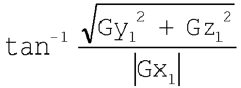 and/or calculating a second (ϕb) intermediate angle on the basis of the first signal (B2) of the second magnetometer (22) by executing the operation:
 generating the reliability angle (ϕ1) on the basis of the first intermediate angle (ϕa) and/or of the second intermediate angle (ϕb), wherein: the reliability angle (ϕ1) is equal to the first angle (ϕa); or the reliability angle (ϕ1) is equal to the second angle (ϕb); or the reliability angle (ϕ1) is equal to an average of the of the first and second angles (ϕa, ϕb); or the reliability angle (ϕ1) is equal to a weighted average of the first and second angles (ϕa, ϕb).
 - The control method according to claim 3, wherein the step of generating the reliability value (K1) includes:calculating a first reliability angle (ϕa) on the basis of the first signals (B1, B2) by executing the operation:
 where Gx1 is a component of the first signal (B1) detected by the first magnetometer (20) along the respective first sensing axis (x1);calculating a second reliability angle (ϕb) on the basis of the first signals (B1, B2) by executing the operation:
 where Gx2 is a component of the second signal (B2) detected by the second magnetometer (22) along the respective first sensing axis (x2); andgenerating the reliability value (K1) on the basis of a first comparison between the first reliability angle (ϕa) and a threshold angle and on the basis of a second comparison between the second reliability angle (ϕb) and said threshold angle.
 - The control method according to any one of the preceding claims, wherein the step of generating the calibration parameter (J1) includes:generating (49a) calibrated data (D2) on the basis of the first signals (B1, B2) through calibration parameters (Pcal);comparing the calibrated data (D2) with respective comparison data, generating a result of said comparison that indicates a need or otherwise to calibrate the first and second magnetometers (20, 22); andif the result of said comparison indicates the need to calibrate the first and second magnetometers, executing the steps of:calibrating (49c) the first and second magnetometers (20, 22) to generate new calibration parameters (Pcal),assigning (49d) to the calibration parameter (J1) a first value indicating execution of the calibration of the first and second magnetometers (20, 22), andreplacing (49c) said calibration parameters (Pcal) with the new calibration parameters (Pcal) generated by calibrating the first and second magnetometers (20, 22).
- The control method according to claim 7, wherein the step of generating (49) the calibration parameter (J1) further includes:
if the result of said comparison does not indicate the need to calibrate the first and second magnetometers, executing the steps of:determining (49e), on the basis of the calibrated data (D2), whether a condition of magnetic interference has been verified at the first and second magnetometers (20, 22); andin the absence of said magnetic interference, assigning (49d) to the calibration parameter (J1) said first value; orin the presence of said magnetic interference, assigning (49f) to the calibration parameter (J1) a second value different from the first value. - The control method according to any one of the preceding claims, wherein the reliability value (K1) is a function of the calibration parameter (J1),
wherein the step of calculating (53) the current value of said lid angle (αLID) comprises recursively updating said current value of the lid angle (αLID) by executing the operation:
- The control method according to any one of the preceding claims, wherein the first hardware element (12; 14) further accommodates a first accelerometer (30; 32), and the second hardware element (14; 12) further accommodates a second accelerometer (32; 30),
the control method further comprising the steps of:acquiring, by the processing unit (27, 28) through the first and second accelerometers (30, 32), second signals indicative of measurements of relative orientation of the first and second hardware elements;calculating (55), by the processing unit (27, 28), a second intermediate value (αLID_ACC) of said lid angle (αLID) on the basis of the second signals; andcalculating (56), by the processing unit (27, 28), said current value of the lid angle (αLID) further on the basis of said second intermediate value (αLID_ACC) of the lid angle (αLID). - The control method according to claim 10, further comprising the step of generating (54), by the processing unit (27, 28) and as a function of the second signals, a further reliability value (K2) indicative of a condition of reliability of the second signals.
- The control method according to claim 11, wherein the step of calculating (56) the current value of the lid angle (αLID) includes executing the operation:
 - the second intermediate value (αLID_ACC), if the reliability value (K1) is equal to 0 and the further reliability value (K2) is other than 0; or- the first intermediate value (αLID_MAG), if the reliability value (K1) is other than 0 and the further reliability value (K2) is equal to 0; or- (K1 · αLID_MAG(t) + K2 . αLID_ACC(t))/(K1 + K2), if the reliability value (K1) is other than 0 and the further reliability value (K2) is other than 0, where αLID_MAG(t) is the first intermediate value, and αLID_ACC(t) is the second intermediate value, K1 is the reliability value and K2 is the further reliability value,and where KLP is equal to 0 if the reliability value (K1) is equal to 0 and the further reliability value (K2) is equal to 0.
 - The control method according to any one of claims 1-9, wherein the first hardware element (12; 14) further accommodates a first gyroscope (40; 42) and the second hardware element (14; 12) further accommodates a second gyroscope (42; 40),
the method further comprising the steps of:acquiring, by the processing unit (27, 28) and through the first and second gyroscopes (40, 42), second signals indicative of measurements of relative orientation of the first and second hardware elements;calculating (58), by the processing unit (27, 28), a second intermediate value (αLID_GYR) of said lid angle (αLID) on the basis of the second signals; andcalculating (60), by the processing unit (27, 28), said current value of the lid angle (αLID) further on the basis of said second intermediate value (αLID_GYR) of the lid angle (αLID). - The control method according to claim 13, wherein the step of calculating the current value of the lid angle (αLID) includes the step of executing a weighted sum of the first intermediate value (αLID_MAG) and of the second intermediate value (αLID_GYR) .
- The control method according to claim 14, wherein the step of executing the weighted sum includes executing the operation:

- An electronic apparatus (10) including:- a first hardware element (12; 14) accommodating a first magnetometer (20; 22); and- a second hardware element (14; 12) accommodating a second magnetometer (22; 20), orientable with respect to the first hardware element (12), and defining a lid angle (αLID) with said first hardware element (12; 14);wherein the first and second magnetometers (20, 22) are configured for generating first signals (B1, B2) that are measurements of a magnetic field (B) external to the electronic apparatus (10) and are indicative of a relative orientation of the first hardware element with respect to the second hardware element,
the electronic apparatus (10) further comprising a processing unit (27, 28) configured for executing the operations of:acquiring said first signals (B1, B2);generating, as a function of the first signals (B1, B2), a calibration parameter (J1) indicative of a condition of calibration of the first and second magnetometers (20, 22) ;generating, as a function of the first signals (B1, B2), a reliability value (K1) indicative of a condition of reliability of the first signals (B1, B2) ;calculating (50) a first intermediate value (αLID_MAG) of said lid angle (αLID) on the basis of the first signals (B1, B2);calculating (53) a current value of said lid angle (αLID) on the basis of the calibration parameter (J1), of the reliability value (K1), and of said first intermediate value (αLID_MAG) of the lid angle (αLID); andcontrolling said function of the electronic apparatus (10) as a function of the current value of the lid angle (αLID). - The electronic apparatus according to claim 16, wherein the first magnetometer (20) is a triaxial magnetometer having a respective first sensing axis (x1), a respective second sensing axis (y1), and a respective third sensing axis (z1) sensing axis, and the second magnetometer (22) is a triaxial magnetometer having a respective first sensing axis (x2), a respective second sensing axis (y2), and a respective third sensing axis (z2), the first sensing axes (x1, x2) being parallel to one another,
and wherein, when said magnetic field (B) acts in a direction parallel to a rotation axis (R) about which the first and second hardware elements (12, 14) are rotatable with respect to one another, only the first sensing axes (x1, x2) are subject to the magnetic field (B), and the processing unit (27, 28) is configured for assigning to the reliability value (K1) a predefined value indicative of unreliability of the first signals (B1, B2). - The electronic apparatus according to claim 16 or claim 17, wherein the first hardware element (12; 14) further accommodates a first accelerometer (30; 32);
wherein the second hardware element (14; 12) further accommodates a second accelerometer (32; 30); and
wherein the processing unit (27, 28) is further configured for executing the operations of:acquiring, through the first and second accelerometers (30, 32), second signals indicative of measurements of relative orientation of the first and second hardware elements;calculating (55) a second intermediate value (αLID_ACC) of said lid angle (αLID) on the basis of the second signals; andcalculating (56) said current value of the lid angle (αLID) further on the basis of said second intermediate value (αLID_ACC) of the lid angle (αLID). - The electronic apparatus according to claim 16 or claim 17, wherein the first hardware element (12; 14) further accommodates a first gyroscope (40; 42), and the second hardware element (14; 12) further accommodates a second gyroscope (42; 40); and
wherein the processing unit (27, 28) is further configured for executing the operations of:acquiring, through the first and second gyroscopes (40, 42), second signals indicative of measurements of relative orientation of the first and second hardware elements;calculating (58) a second intermediate value (αLID_GYR) of said lid angle (αLID) on the basis of the second signals; andcalculating (60) said current value of the lid angle (αLID) on the basis of said second intermediate value (αLID_GYR) of the lid angle (αLID). - The electronic apparatus according to any one of claims 16-19, wherein the first hardware element (12) is provided with a first user-interaction device (18) and the second hardware element (14) is provided with a second user-interaction device (16), and wherein the operation of controlling said function of the electronic apparatus (10) comprises adapting operative features or operation features of the first interaction device (18) and/or of the second interaction device (16) as a function of the current value of the lid angle (αLID).
- A software product to be loaded into a processing unit (27, 28) of an electronic apparatus (10) comprising a first hardware element (12; 14) accommodating a first magnetometer (20; 22), and a second hardware element (14; 12) accommodating a second magnetometer (22; 20), orientable with respect to the first hardware element (12), and defining a lid angle (αLID) with said first hardware element (12; 14); wherein the first and second magnetometers (20, 22) are configured for generating first signals (B1, B2) that are measurements of a magnetic field (B) external to the electronic apparatus (10) and are indicative of a relative orientation of the first hardware element with respect to the second hardware element,
said software product being designed in such a way that, when it is run, the processing unit (27, 28) becomes configured for:acquiring said first signals (B1, B2);generating, as a function of the first signals (B1, B2), a calibration parameter (J1) indicative of a condition of calibration of the first and second magnetometers (20, 22) ;generating, as a function of the first signals (B1, B2), a reliability value (K1) indicative of a condition of reliability of the first signals (B1, B2);calculating (50) a first intermediate value (αLID_MAG) of said lid angle (αLID) on the basis of the first signals (B1, B2);calculating (53) a current value of said lid angle (αLID) on the basis of the calibration parameter (J1), of the reliability value (K1), and of said first intermediate value (αLID_MAG) of the lid angle (αLID); andcontrolling said function of the electronic apparatus (10) as a function of the current value of the lid angle (αLID).
Applications Claiming Priority (1)
| Application Number | Priority Date | Filing Date | Title |
|---|---|---|---|
| IT102020000009937A IT202000009937A1 (en) | 2020-05-05 | 2020-05-05 | METHOD OF CHECKING AN ELECTRONIC DEVICE BY CALCULATION OF AN OPENING ANGLE, RELATED ELECTRONIC DEVICE AND SOFTWARE PRODUCT |
Publications (2)
| Publication Number | Publication Date |
|---|---|
| EP3907465A1 true EP3907465A1 (en) | 2021-11-10 |
| EP3907465B1 EP3907465B1 (en) | 2022-11-23 |
Family
ID=71452689
Family Applications (1)
| Application Number | Title | Priority Date | Filing Date |
|---|---|---|---|
| EP21171687.3A Active EP3907465B1 (en) | 2020-05-05 | 2021-04-30 | Electronic apparatus control method performed through lid angle calculation, electronic apparatus thereof and software product |
Country Status (3)
| Country | Link |
|---|---|
| US (1) | US11656071B2 (en) |
| EP (1) | EP3907465B1 (en) |
| IT (1) | IT202000009937A1 (en) |
Cited By (2)
| Publication number | Priority date | Publication date | Assignee | Title |
|---|---|---|---|---|
| EP4390467A1 (en) * | 2022-12-22 | 2024-06-26 | Advanced Magnetic Interaction, AMI | Passive accessories |
| EP4390634A1 (en) * | 2022-12-22 | 2024-06-26 | Advanced Magnetic Interaction, AMI | Electronic device comprising magnetometers |
Families Citing this family (12)
| Publication number | Priority date | Publication date | Assignee | Title |
|---|---|---|---|---|
| IT201700057066A1 (en) | 2017-05-25 | 2018-11-25 | St Microelectronics Srl | PROCESSING SYSTEM IMPLEMENTING AN ALGORITHM FOR THE MERGER OF DATA FROM INERTIAL SENSORS, AND METHOD |
| US11407098B2 (en) | 2019-11-26 | 2022-08-09 | Stmicroelectronics S.R.L. | Smart push button device utilizing MEMS sensors |
| CN113608576B (en) | 2020-05-05 | 2024-06-25 | 意法半导体股份有限公司 | Electronic device control method, electronic device and software product thereof |
| EP3913326B1 (en) * | 2020-05-20 | 2023-12-27 | Roche Diagnostics GmbH | Sample container spring check apparatus |
| US12487642B2 (en) * | 2021-07-19 | 2025-12-02 | Invensense, Inc. | Method and system for determining hinge angle |
| CN116781809B (en) * | 2021-11-19 | 2024-07-05 | 荣耀终端有限公司 | Hinge angle detection method and related equipment |
| CN116366750B (en) * | 2021-12-28 | 2024-04-16 | 荣耀终端有限公司 | Method for determining folding screen angle and related equipment |
| CN219435121U (en) * | 2022-05-20 | 2023-07-28 | 台湾东电化股份有限公司 | Optical element driving mechanism |
| US12259760B2 (en) | 2022-05-27 | 2025-03-25 | Stmicroelectronics S.R.L. | Lid angle detection |
| US12146894B2 (en) | 2022-05-27 | 2024-11-19 | Stmicroelectronics S.R.L. | Lid angle detection |
| CN117631756A (en) * | 2022-08-09 | 2024-03-01 | 北京小米移动软件有限公司 | Device control method, device, medium, and program product |
| CN118042043A (en) * | 2022-11-04 | 2024-05-14 | 荣耀终端有限公司 | Method for controlling screen brightness and electronic device |
Citations (4)
| Publication number | Priority date | Publication date | Assignee | Title |
|---|---|---|---|---|
| US20170010657A1 (en) * | 2015-07-06 | 2017-01-12 | Google Inc. | Accelerometer based hall effect sensor filtering for computing devices |
| US20170235355A1 (en) * | 2016-02-17 | 2017-08-17 | Lenovo Enterprise Solutions (Singapore) Pte. Ltd. | Laptop component power consumption settings responsive to multiple lid angles |
| EP3407157A1 (en) | 2017-05-25 | 2018-11-28 | STMicroelectronics S.r.l. | Computing system implementing an algorithm for fusing data from inertial sensors, and method |
| WO2019168735A1 (en) * | 2018-02-28 | 2019-09-06 | Idhl Holdings, Inc. | Methods and apparatus for planar magnetometer calibration, heading determination, gyroscope assisted magnetometer amplitude calibration, magnetometer amplitude and alignment calibration, magnetometer mapping, and sensor fusion |
Family Cites Families (48)
| Publication number | Priority date | Publication date | Assignee | Title |
|---|---|---|---|---|
| US5704435A (en) | 1995-08-17 | 1998-01-06 | Milwaukee Electric Tool Corporation | Hand held power tool including inertia switch |
| FR2752084B1 (en) | 1996-08-05 | 1998-10-09 | Socomec Sa | SWITCHING APPARATUS FOR AN ELECTRICAL INSTALLATION, MULTIPOLAR SWITCH AND INVERTER SWITCH PROVIDED WITH SAID APPARATUS |
| DE19942156A1 (en) | 1999-09-03 | 2001-03-08 | Hilti Ag | Switching device for multifunctional hand-held machine tools |
| JP4061473B2 (en) | 2002-04-26 | 2008-03-19 | 日本電気株式会社 | Folding mobile phone |
| DE10353050B4 (en) | 2003-11-13 | 2007-01-04 | Siemens Ag | Device for compensating a caused by the gyrostatic effect torque |
| KR101123338B1 (en) | 2007-04-13 | 2012-03-27 | 키네틱 인코포레이티드 | A Movement Sensing Apparatus of an Object |
| US9062971B2 (en) | 2008-03-06 | 2015-06-23 | Texas Instruments Incorporated | E-compass, tilt sensor, memory and processor with coarse detilting procedure |
| TW201006528A (en) | 2008-08-06 | 2010-02-16 | Cywee Group Ltd | Inertia sensing device |
| KR101569776B1 (en) | 2009-01-09 | 2015-11-19 | 삼성전자주식회사 | Foldable Display Device And Operation Method thereof |
| US10054444B2 (en) | 2009-05-29 | 2018-08-21 | Qualcomm Incorporated | Method and apparatus for accurate acquisition of inertial sensor data |
| CN201493816U (en) | 2009-07-13 | 2010-06-02 | 南京德朔实业有限公司 | Electric tool |
| US8118815B2 (en) | 2009-07-24 | 2012-02-21 | OrthAlign, Inc. | Systems and methods for joint replacement |
| JP5611780B2 (en) | 2010-11-11 | 2014-10-22 | 株式会社マキタ | Shift switch |
| US9436231B2 (en) | 2011-04-07 | 2016-09-06 | Qualcomm Incorporated | Rest detection using accelerometer |
| US10509466B1 (en) | 2011-05-11 | 2019-12-17 | Snap Inc. | Headwear with computer and optical element for use therewith and systems utilizing same |
| CA2847182C (en) | 2011-09-02 | 2020-02-11 | Stryker Corporation | Surgical instrument including a cutting accessory extending from a housing and actuators that establish the position of the cutting accessory relative to the housing |
| JP5821032B2 (en) | 2011-09-20 | 2015-11-24 | パナソニックIpマネジメント株式会社 | Slide switch for electric tools |
| US9193055B2 (en) | 2012-04-13 | 2015-11-24 | Black & Decker Inc. | Electronic clutch for power tool |
| US8847979B2 (en) | 2012-06-08 | 2014-09-30 | Samuel G. Smith | Peek mode and graphical user interface (GUI) experience |
| CN104684841A (en) | 2012-06-13 | 2015-06-03 | 普渡研究基金会 | Microelectromechanical system and methods of use |
| US9135705B2 (en) * | 2012-10-16 | 2015-09-15 | Qualcomm Incorporated | Sensor calibration and position estimation based on vanishing point determination |
| US10132829B2 (en) * | 2013-03-13 | 2018-11-20 | Invensense, Inc. | Heading confidence interval estimation |
| CN104461330A (en) | 2013-09-18 | 2015-03-25 | 联想(北京)有限公司 | Information processing method and electronic device |
| US9606664B2 (en) | 2013-11-13 | 2017-03-28 | Dell Products, Lp | Dynamic hover sensitivity and gesture adaptation in a dual display system |
| US9524139B2 (en) | 2013-10-29 | 2016-12-20 | Dell Products, Lp | System and method for positioning an application window based on usage context for dual screen display device |
| US9916031B2 (en) * | 2013-12-26 | 2018-03-13 | Intel Corporation | Mechanism to avoid unintentional user interaction with a convertible mobile device during conversion |
| EP2930467A1 (en) | 2014-04-11 | 2015-10-14 | Airbus Defence and Space GmbH | A system and method for sensing the inclination of a moving platform with respect to gravity |
| DE102014112982A1 (en) | 2014-09-09 | 2016-03-10 | Johnson Electric Germany GmbH & Co. KG | Electric switch |
| CN107072674A (en) | 2014-09-23 | 2017-08-18 | 思外科有限公司 | Many plane variable-geometry saw cut radial type borer systems |
| US9557775B2 (en) | 2014-11-21 | 2017-01-31 | Google Inc. | Detecting an operating mode of a computing device using accelerometers |
| WO2016119748A1 (en) | 2015-01-29 | 2016-08-04 | 苏州宝时得电动工具有限公司 | Hand-held power tool and operating method thereof |
| US9612625B2 (en) | 2015-03-02 | 2017-04-04 | Blackberry Limited | System and method of rendering data based on an angle of a carrying case flap |
| CN105983949B (en) | 2015-03-03 | 2018-11-09 | 苏州宝时得电动工具有限公司 | Power tool and its operating method |
| US20170299388A9 (en) | 2015-05-22 | 2017-10-19 | InvenSense, Incorporated | Systems and methods for synthetic sensor signal generation |
| US10114464B2 (en) | 2015-06-30 | 2018-10-30 | Stmicroelectronics S.R.L. | Device and method for determination of angular position in three-dimensional space, and corresponding electronic apparatus |
| KR20170028193A (en) | 2015-09-03 | 2017-03-13 | 삼성전자주식회사 | Electronic device including hidden display and method for displaying information thereof |
| US9897465B2 (en) | 2015-09-22 | 2018-02-20 | Apple Inc. | Portable computer sleep mode system with angle sensor |
| US10386203B1 (en) | 2015-11-05 | 2019-08-20 | Invensense, Inc. | Systems and methods for gyroscope calibration |
| CN205289837U (en) | 2015-12-05 | 2016-06-08 | 温州敦和电子科技有限公司 | Sustainable power supply electric hand drill |
| CN105424040B (en) | 2016-01-15 | 2019-09-13 | 极翼机器人(上海)有限公司 | A kind of novel MEMS inertial sensor array redundant configurations method |
| US10403960B2 (en) * | 2016-03-31 | 2019-09-03 | Dell Products L.P. | System and method for antenna optimization |
| US10558277B2 (en) | 2016-08-04 | 2020-02-11 | Microsoft Technology Licensing, Llc | Folding angle sensing of a foldable device |
| CN106482734A (en) | 2016-09-28 | 2017-03-08 | 湖南优象科技有限公司 | A kind of filtering method for IMU Fusion |
| US10198086B2 (en) | 2016-10-27 | 2019-02-05 | Fluidity Technologies, Inc. | Dynamically balanced, multi-degrees-of-freedom hand controller |
| EP3700713B1 (en) | 2017-10-26 | 2023-07-12 | Milwaukee Electric Tool Corporation | Kickback control methods for power tools |
| JP2019130626A (en) | 2018-01-31 | 2019-08-08 | 株式会社マキタ | Electric tool |
| CN108762324A (en) | 2018-05-23 | 2018-11-06 | 深圳市道通智能航空技术有限公司 | Horizontal stage electric machine angle and angular speed evaluation method, device, holder and aircraft |
| US11407098B2 (en) | 2019-11-26 | 2022-08-09 | Stmicroelectronics S.R.L. | Smart push button device utilizing MEMS sensors |
-
2020
- 2020-05-05 IT IT102020000009937A patent/IT202000009937A1/en unknown
-
2021
- 2021-04-22 US US17/237,844 patent/US11656071B2/en active Active
- 2021-04-30 EP EP21171687.3A patent/EP3907465B1/en active Active
Patent Citations (4)
| Publication number | Priority date | Publication date | Assignee | Title |
|---|---|---|---|---|
| US20170010657A1 (en) * | 2015-07-06 | 2017-01-12 | Google Inc. | Accelerometer based hall effect sensor filtering for computing devices |
| US20170235355A1 (en) * | 2016-02-17 | 2017-08-17 | Lenovo Enterprise Solutions (Singapore) Pte. Ltd. | Laptop component power consumption settings responsive to multiple lid angles |
| EP3407157A1 (en) | 2017-05-25 | 2018-11-28 | STMicroelectronics S.r.l. | Computing system implementing an algorithm for fusing data from inertial sensors, and method |
| WO2019168735A1 (en) * | 2018-02-28 | 2019-09-06 | Idhl Holdings, Inc. | Methods and apparatus for planar magnetometer calibration, heading determination, gyroscope assisted magnetometer amplitude calibration, magnetometer amplitude and alignment calibration, magnetometer mapping, and sensor fusion |
Cited By (4)
| Publication number | Priority date | Publication date | Assignee | Title |
|---|---|---|---|---|
| EP4390467A1 (en) * | 2022-12-22 | 2024-06-26 | Advanced Magnetic Interaction, AMI | Passive accessories |
| EP4390634A1 (en) * | 2022-12-22 | 2024-06-26 | Advanced Magnetic Interaction, AMI | Electronic device comprising magnetometers |
| WO2024132875A1 (en) * | 2022-12-22 | 2024-06-27 | Advanced Magnetic Interaction, Ami | Electronic device comprising magnetometers |
| WO2024132880A1 (en) * | 2022-12-22 | 2024-06-27 | Advanced Magnetic Interaction, Ami | Passive accessories |
Also Published As
| Publication number | Publication date |
|---|---|
| US20210348911A1 (en) | 2021-11-11 |
| EP3907465B1 (en) | 2022-11-23 |
| IT202000009937A1 (en) | 2021-11-05 |
| US11656071B2 (en) | 2023-05-23 |
Similar Documents
| Publication | Publication Date | Title |
|---|---|---|
| EP3907465B1 (en) | Electronic apparatus control method performed through lid angle calculation, electronic apparatus thereof and software product | |
| US12007237B2 (en) | Electronic apparatus control method performed through lid angle calculation, electronic apparatus thereof and software product | |
| US11473894B2 (en) | Computing system implementing an algorithm for fusing data from inertial sensors, and method | |
| US10816570B2 (en) | Heading confidence interval estimation | |
| CN103153790B (en) | The measurement data of the magnetometer using motion sensor and be attached to device estimates equipment and the method for this device yaw angle in gravitational frame of reference | |
| US10209078B2 (en) | Local perturbation rejection using time shifting | |
| CN103941309B (en) | Geomagnetic sensor calibration device and method thereof | |
| Roetenberg et al. | Inertial and magnetic sensing of human movement near ferromagnetic materials | |
| KR20110081205A (en) | Electronic compass | |
| CN114719846B (en) | System and method for fast magnetometer calibration using a gyroscope | |
| JP6983565B2 (en) | Methods and systems for compensating for soft iron magnetic disturbances in vehicle heading reference systems | |
| Ghasemi‐Moghadam et al. | Attitude determination by combining arrays of MEMS accelerometers, gyros, and magnetometers via quaternion‐based complementary filter | |
| CN119572213B (en) | Well deviation and geomagnetic field intensity measurement system based on high-precision fluxgate sensor | |
| US20150241390A1 (en) | Automatically updating hard iron and soft iron coefficients of a magnetic sensor | |
| Velázquez et al. | A new algorithm for fault tolerance in redundant sensor systems based on real-time variance estimation | |
| US20190346281A1 (en) | System and method for sensor calibration | |
| Bangera et al. | MEMS-based IMU for pose estimation | |
| CN114964214B (en) | Extended Kalman filtering attitude calculation method of attitude heading reference system | |
| US10444030B1 (en) | Automatic calibration of magnetic sensors based on optical image tracking | |
| CA2822336C (en) | Stabilizing orientation values of an electronic device | |
| JP2012251870A (en) | Angular velocity detection method and apparatus for the same |
Legal Events
| Date | Code | Title | Description |
|---|---|---|---|
| PUAI | Public reference made under article 153(3) epc to a published international application that has entered the european phase |
Free format text: ORIGINAL CODE: 0009012 |
|
| STAA | Information on the status of an ep patent application or granted ep patent |
Free format text: STATUS: THE APPLICATION HAS BEEN PUBLISHED |
|
| AK | Designated contracting states |
Kind code of ref document: A1 Designated state(s): AL AT BE BG CH CY CZ DE DK EE ES FI FR GB GR HR HU IE IS IT LI LT LU LV MC MK MT NL NO PL PT RO RS SE SI SK SM TR |
|
| B565 | Issuance of search results under rule 164(2) epc |
Effective date: 20210917 |
|
| STAA | Information on the status of an ep patent application or granted ep patent |
Free format text: STATUS: REQUEST FOR EXAMINATION WAS MADE |
|
| 17P | Request for examination filed |
Effective date: 20220222 |
|
| RBV | Designated contracting states (corrected) |
Designated state(s): AL AT BE BG CH CY CZ DE DK EE ES FI FR GB GR HR HU IE IS IT LI LT LU LV MC MK MT NL NO PL PT RO RS SE SI SK SM TR |
|
| GRAP | Despatch of communication of intention to grant a patent |
Free format text: ORIGINAL CODE: EPIDOSNIGR1 |
|
| STAA | Information on the status of an ep patent application or granted ep patent |
Free format text: STATUS: GRANT OF PATENT IS INTENDED |
|
| INTG | Intention to grant announced |
Effective date: 20220617 |
|
| GRAS | Grant fee paid |
Free format text: ORIGINAL CODE: EPIDOSNIGR3 |
|
| GRAA | (expected) grant |
Free format text: ORIGINAL CODE: 0009210 |
|
| STAA | Information on the status of an ep patent application or granted ep patent |
Free format text: STATUS: THE PATENT HAS BEEN GRANTED |
|
| AK | Designated contracting states |
Kind code of ref document: B1 Designated state(s): AL AT BE BG CH CY CZ DE DK EE ES FI FR GB GR HR HU IE IS IT LI LT LU LV MC MK MT NL NO PL PT RO RS SE SI SK SM TR |
|
| REG | Reference to a national code |
Ref country code: GB Ref legal event code: FG4D |
|
| REG | Reference to a national code |
Ref country code: CH Ref legal event code: EP |
|
| REG | Reference to a national code |
Ref country code: AT Ref legal event code: REF Ref document number: 1533377 Country of ref document: AT Kind code of ref document: T Effective date: 20221215 Ref country code: DE Ref legal event code: R096 Ref document number: 602021000812 Country of ref document: DE |
|
| REG | Reference to a national code |
Ref country code: IE Ref legal event code: FG4D |
|
| REG | Reference to a national code |
Ref country code: LT Ref legal event code: MG9D |
|
| REG | Reference to a national code |
Ref country code: NL Ref legal event code: MP Effective date: 20221123 |
|
| REG | Reference to a national code |
Ref country code: AT Ref legal event code: MK05 Ref document number: 1533377 Country of ref document: AT Kind code of ref document: T Effective date: 20221123 |
|
| PG25 | Lapsed in a contracting state [announced via postgrant information from national office to epo] |
Ref country code: SE Free format text: LAPSE BECAUSE OF FAILURE TO SUBMIT A TRANSLATION OF THE DESCRIPTION OR TO PAY THE FEE WITHIN THE PRESCRIBED TIME-LIMIT Effective date: 20221123 Ref country code: PT Free format text: LAPSE BECAUSE OF FAILURE TO SUBMIT A TRANSLATION OF THE DESCRIPTION OR TO PAY THE FEE WITHIN THE PRESCRIBED TIME-LIMIT Effective date: 20230323 Ref country code: NO Free format text: LAPSE BECAUSE OF FAILURE TO SUBMIT A TRANSLATION OF THE DESCRIPTION OR TO PAY THE FEE WITHIN THE PRESCRIBED TIME-LIMIT Effective date: 20230223 Ref country code: LT Free format text: LAPSE BECAUSE OF FAILURE TO SUBMIT A TRANSLATION OF THE DESCRIPTION OR TO PAY THE FEE WITHIN THE PRESCRIBED TIME-LIMIT Effective date: 20221123 Ref country code: FI Free format text: LAPSE BECAUSE OF FAILURE TO SUBMIT A TRANSLATION OF THE DESCRIPTION OR TO PAY THE FEE WITHIN THE PRESCRIBED TIME-LIMIT Effective date: 20221123 Ref country code: ES Free format text: LAPSE BECAUSE OF FAILURE TO SUBMIT A TRANSLATION OF THE DESCRIPTION OR TO PAY THE FEE WITHIN THE PRESCRIBED TIME-LIMIT Effective date: 20221123 Ref country code: AT Free format text: LAPSE BECAUSE OF FAILURE TO SUBMIT A TRANSLATION OF THE DESCRIPTION OR TO PAY THE FEE WITHIN THE PRESCRIBED TIME-LIMIT Effective date: 20221123 |
|
| PG25 | Lapsed in a contracting state [announced via postgrant information from national office to epo] |
Ref country code: RS Free format text: LAPSE BECAUSE OF FAILURE TO SUBMIT A TRANSLATION OF THE DESCRIPTION OR TO PAY THE FEE WITHIN THE PRESCRIBED TIME-LIMIT Effective date: 20221123 Ref country code: PL Free format text: LAPSE BECAUSE OF FAILURE TO SUBMIT A TRANSLATION OF THE DESCRIPTION OR TO PAY THE FEE WITHIN THE PRESCRIBED TIME-LIMIT Effective date: 20221123 Ref country code: LV Free format text: LAPSE BECAUSE OF FAILURE TO SUBMIT A TRANSLATION OF THE DESCRIPTION OR TO PAY THE FEE WITHIN THE PRESCRIBED TIME-LIMIT Effective date: 20221123 Ref country code: IS Free format text: LAPSE BECAUSE OF FAILURE TO SUBMIT A TRANSLATION OF THE DESCRIPTION OR TO PAY THE FEE WITHIN THE PRESCRIBED TIME-LIMIT Effective date: 20230323 Ref country code: HR Free format text: LAPSE BECAUSE OF FAILURE TO SUBMIT A TRANSLATION OF THE DESCRIPTION OR TO PAY THE FEE WITHIN THE PRESCRIBED TIME-LIMIT Effective date: 20221123 Ref country code: GR Free format text: LAPSE BECAUSE OF FAILURE TO SUBMIT A TRANSLATION OF THE DESCRIPTION OR TO PAY THE FEE WITHIN THE PRESCRIBED TIME-LIMIT Effective date: 20230224 |
|
| PG25 | Lapsed in a contracting state [announced via postgrant information from national office to epo] |
Ref country code: NL Free format text: LAPSE BECAUSE OF FAILURE TO SUBMIT A TRANSLATION OF THE DESCRIPTION OR TO PAY THE FEE WITHIN THE PRESCRIBED TIME-LIMIT Effective date: 20221123 |
|
| PG25 | Lapsed in a contracting state [announced via postgrant information from national office to epo] |
Ref country code: SM Free format text: LAPSE BECAUSE OF FAILURE TO SUBMIT A TRANSLATION OF THE DESCRIPTION OR TO PAY THE FEE WITHIN THE PRESCRIBED TIME-LIMIT Effective date: 20221123 Ref country code: RO Free format text: LAPSE BECAUSE OF FAILURE TO SUBMIT A TRANSLATION OF THE DESCRIPTION OR TO PAY THE FEE WITHIN THE PRESCRIBED TIME-LIMIT Effective date: 20221123 Ref country code: EE Free format text: LAPSE BECAUSE OF FAILURE TO SUBMIT A TRANSLATION OF THE DESCRIPTION OR TO PAY THE FEE WITHIN THE PRESCRIBED TIME-LIMIT Effective date: 20221123 Ref country code: DK Free format text: LAPSE BECAUSE OF FAILURE TO SUBMIT A TRANSLATION OF THE DESCRIPTION OR TO PAY THE FEE WITHIN THE PRESCRIBED TIME-LIMIT Effective date: 20221123 Ref country code: CZ Free format text: LAPSE BECAUSE OF FAILURE TO SUBMIT A TRANSLATION OF THE DESCRIPTION OR TO PAY THE FEE WITHIN THE PRESCRIBED TIME-LIMIT Effective date: 20221123 |
|
| REG | Reference to a national code |
Ref country code: DE Ref legal event code: R097 Ref document number: 602021000812 Country of ref document: DE |
|
| PG25 | Lapsed in a contracting state [announced via postgrant information from national office to epo] |
Ref country code: SK Free format text: LAPSE BECAUSE OF FAILURE TO SUBMIT A TRANSLATION OF THE DESCRIPTION OR TO PAY THE FEE WITHIN THE PRESCRIBED TIME-LIMIT Effective date: 20221123 Ref country code: AL Free format text: LAPSE BECAUSE OF FAILURE TO SUBMIT A TRANSLATION OF THE DESCRIPTION OR TO PAY THE FEE WITHIN THE PRESCRIBED TIME-LIMIT Effective date: 20221123 |
|
| PLBE | No opposition filed within time limit |
Free format text: ORIGINAL CODE: 0009261 |
|
| STAA | Information on the status of an ep patent application or granted ep patent |
Free format text: STATUS: NO OPPOSITION FILED WITHIN TIME LIMIT |
|
| 26N | No opposition filed |
Effective date: 20230824 |
|
| PG25 | Lapsed in a contracting state [announced via postgrant information from national office to epo] |
Ref country code: SI Free format text: LAPSE BECAUSE OF FAILURE TO SUBMIT A TRANSLATION OF THE DESCRIPTION OR TO PAY THE FEE WITHIN THE PRESCRIBED TIME-LIMIT Effective date: 20221123 |
|
| PG25 | Lapsed in a contracting state [announced via postgrant information from national office to epo] |
Ref country code: LU Free format text: LAPSE BECAUSE OF NON-PAYMENT OF DUE FEES Effective date: 20230430 |
|
| REG | Reference to a national code |
Ref country code: BE Ref legal event code: MM Effective date: 20230430 |
|
| PG25 | Lapsed in a contracting state [announced via postgrant information from national office to epo] |
Ref country code: MC Free format text: LAPSE BECAUSE OF FAILURE TO SUBMIT A TRANSLATION OF THE DESCRIPTION OR TO PAY THE FEE WITHIN THE PRESCRIBED TIME-LIMIT Effective date: 20221123 |
|
| PG25 | Lapsed in a contracting state [announced via postgrant information from national office to epo] |
Ref country code: MC Free format text: LAPSE BECAUSE OF FAILURE TO SUBMIT A TRANSLATION OF THE DESCRIPTION OR TO PAY THE FEE WITHIN THE PRESCRIBED TIME-LIMIT Effective date: 20221123 Ref country code: FR Free format text: LAPSE BECAUSE OF NON-PAYMENT OF DUE FEES Effective date: 20230430 |
|
| REG | Reference to a national code |
Ref country code: IE Ref legal event code: MM4A |
|
| PG25 | Lapsed in a contracting state [announced via postgrant information from national office to epo] |
Ref country code: BE Free format text: LAPSE BECAUSE OF NON-PAYMENT OF DUE FEES Effective date: 20230430 |
|
| PG25 | Lapsed in a contracting state [announced via postgrant information from national office to epo] |
Ref country code: IE Free format text: LAPSE BECAUSE OF NON-PAYMENT OF DUE FEES Effective date: 20230430 |
|
| PG25 | Lapsed in a contracting state [announced via postgrant information from national office to epo] |
Ref country code: IE Free format text: LAPSE BECAUSE OF NON-PAYMENT OF DUE FEES Effective date: 20230430 |
|
| PG25 | Lapsed in a contracting state [announced via postgrant information from national office to epo] |
Ref country code: IT Free format text: LAPSE BECAUSE OF FAILURE TO SUBMIT A TRANSLATION OF THE DESCRIPTION OR TO PAY THE FEE WITHIN THE PRESCRIBED TIME-LIMIT Effective date: 20221123 |
|
| PG25 | Lapsed in a contracting state [announced via postgrant information from national office to epo] |
Ref country code: BG Free format text: LAPSE BECAUSE OF FAILURE TO SUBMIT A TRANSLATION OF THE DESCRIPTION OR TO PAY THE FEE WITHIN THE PRESCRIBED TIME-LIMIT Effective date: 20221123 |
|
| PG25 | Lapsed in a contracting state [announced via postgrant information from national office to epo] |
Ref country code: BG Free format text: LAPSE BECAUSE OF FAILURE TO SUBMIT A TRANSLATION OF THE DESCRIPTION OR TO PAY THE FEE WITHIN THE PRESCRIBED TIME-LIMIT Effective date: 20221123 |
|
| REG | Reference to a national code |
Ref country code: CH Ref legal event code: PL |
|
| PG25 | Lapsed in a contracting state [announced via postgrant information from national office to epo] |
Ref country code: CH Free format text: LAPSE BECAUSE OF NON-PAYMENT OF DUE FEES Effective date: 20240430 |
|
| PGFP | Annual fee paid to national office [announced via postgrant information from national office to epo] |
Ref country code: DE Payment date: 20250319 Year of fee payment: 5 |
|
| PG25 | Lapsed in a contracting state [announced via postgrant information from national office to epo] |
Ref country code: CY Free format text: LAPSE BECAUSE OF FAILURE TO SUBMIT A TRANSLATION OF THE DESCRIPTION OR TO PAY THE FEE WITHIN THE PRESCRIBED TIME-LIMIT; INVALID AB INITIO Effective date: 20210430 |
|
| PG25 | Lapsed in a contracting state [announced via postgrant information from national office to epo] |
Ref country code: HU Free format text: LAPSE BECAUSE OF FAILURE TO SUBMIT A TRANSLATION OF THE DESCRIPTION OR TO PAY THE FEE WITHIN THE PRESCRIBED TIME-LIMIT; INVALID AB INITIO Effective date: 20210430 |
|
| PG25 | Lapsed in a contracting state [announced via postgrant information from national office to epo] |
Ref country code: TR Free format text: LAPSE BECAUSE OF FAILURE TO SUBMIT A TRANSLATION OF THE DESCRIPTION OR TO PAY THE FEE WITHIN THE PRESCRIBED TIME-LIMIT Effective date: 20221123 |
|
| GBPC | Gb: european patent ceased through non-payment of renewal fee |
Effective date: 20250430 |
|
| PG25 | Lapsed in a contracting state [announced via postgrant information from national office to epo] |
Ref country code: GB Free format text: LAPSE BECAUSE OF NON-PAYMENT OF DUE FEES Effective date: 20250430 |