EP3907452B1 - Refrigeration and freezing apparatus - Google Patents
Refrigeration and freezing apparatus Download PDFInfo
- Publication number
- EP3907452B1 EP3907452B1 EP19906611.9A EP19906611A EP3907452B1 EP 3907452 B1 EP3907452 B1 EP 3907452B1 EP 19906611 A EP19906611 A EP 19906611A EP 3907452 B1 EP3907452 B1 EP 3907452B1
- Authority
- EP
- European Patent Office
- Prior art keywords
- cylinder body
- refrigerating
- generating module
- electromagnetic
- disposed
- Prior art date
- Legal status (The legal status is an assumption and is not a legal conclusion. Google has not performed a legal analysis and makes no representation as to the accuracy of the status listed.)
- Active
Links
Images




Classifications
-
- H—ELECTRICITY
- H05—ELECTRIC TECHNIQUES NOT OTHERWISE PROVIDED FOR
- H05B—ELECTRIC HEATING; ELECTRIC LIGHT SOURCES NOT OTHERWISE PROVIDED FOR; CIRCUIT ARRANGEMENTS FOR ELECTRIC LIGHT SOURCES, IN GENERAL
- H05B6/00—Heating by electric, magnetic or electromagnetic fields
- H05B6/64—Heating using microwaves
- H05B6/72—Radiators or antennas
-
- F—MECHANICAL ENGINEERING; LIGHTING; HEATING; WEAPONS; BLASTING
- F25—REFRIGERATION OR COOLING; COMBINED HEATING AND REFRIGERATION SYSTEMS; HEAT PUMP SYSTEMS; MANUFACTURE OR STORAGE OF ICE; LIQUEFACTION SOLIDIFICATION OF GASES
- F25D—REFRIGERATORS; COLD ROOMS; ICE-BOXES; COOLING OR FREEZING APPARATUS NOT OTHERWISE PROVIDED FOR
- F25D31/00—Other cooling or freezing apparatus
- F25D31/005—Combined cooling and heating devices
-
- F—MECHANICAL ENGINEERING; LIGHTING; HEATING; WEAPONS; BLASTING
- F25—REFRIGERATION OR COOLING; COMBINED HEATING AND REFRIGERATION SYSTEMS; HEAT PUMP SYSTEMS; MANUFACTURE OR STORAGE OF ICE; LIQUEFACTION SOLIDIFICATION OF GASES
- F25D—REFRIGERATORS; COLD ROOMS; ICE-BOXES; COOLING OR FREEZING APPARATUS NOT OTHERWISE PROVIDED FOR
- F25D23/00—General constructional features
- F25D23/12—Arrangements of compartments additional to cooling compartments; Combinations of refrigerators with other equipment, e.g. stove
-
- H—ELECTRICITY
- H05—ELECTRIC TECHNIQUES NOT OTHERWISE PROVIDED FOR
- H05B—ELECTRIC HEATING; ELECTRIC LIGHT SOURCES NOT OTHERWISE PROVIDED FOR; CIRCUIT ARRANGEMENTS FOR ELECTRIC LIGHT SOURCES, IN GENERAL
- H05B6/00—Heating by electric, magnetic or electromagnetic fields
- H05B6/02—Induction heating
- H05B6/10—Induction heating apparatus, other than furnaces, for specific applications
- H05B6/12—Cooking devices
-
- H—ELECTRICITY
- H05—ELECTRIC TECHNIQUES NOT OTHERWISE PROVIDED FOR
- H05B—ELECTRIC HEATING; ELECTRIC LIGHT SOURCES NOT OTHERWISE PROVIDED FOR; CIRCUIT ARRANGEMENTS FOR ELECTRIC LIGHT SOURCES, IN GENERAL
- H05B6/00—Heating by electric, magnetic or electromagnetic fields
- H05B6/64—Heating using microwaves
- H05B6/80—Apparatus for specific applications
-
- A—HUMAN NECESSITIES
- A23—FOODS OR FOODSTUFFS; TREATMENT THEREOF, NOT COVERED BY OTHER CLASSES
- A23B—PRESERVATION OF FOODS, FOODSTUFFS OR NON-ALCOHOLIC BEVERAGES; CHEMICAL RIPENING OF FRUIT OR VEGETABLES
- A23B2/00—Preservation of foods or foodstuffs, in general
- A23B2/80—Freezing; Subsequent thawing; Cooling
- A23B2/82—Thawing subsequent to freezing
-
- F—MECHANICAL ENGINEERING; LIGHTING; HEATING; WEAPONS; BLASTING
- F25—REFRIGERATION OR COOLING; COMBINED HEATING AND REFRIGERATION SYSTEMS; HEAT PUMP SYSTEMS; MANUFACTURE OR STORAGE OF ICE; LIQUEFACTION SOLIDIFICATION OF GASES
- F25D—REFRIGERATORS; COLD ROOMS; ICE-BOXES; COOLING OR FREEZING APPARATUS NOT OTHERWISE PROVIDED FOR
- F25D23/00—General constructional features
- F25D23/006—General constructional features for mounting refrigerating machinery components
-
- F—MECHANICAL ENGINEERING; LIGHTING; HEATING; WEAPONS; BLASTING
- F25—REFRIGERATION OR COOLING; COMBINED HEATING AND REFRIGERATION SYSTEMS; HEAT PUMP SYSTEMS; MANUFACTURE OR STORAGE OF ICE; LIQUEFACTION SOLIDIFICATION OF GASES
- F25D—REFRIGERATORS; COLD ROOMS; ICE-BOXES; COOLING OR FREEZING APPARATUS NOT OTHERWISE PROVIDED FOR
- F25D2400/00—General features of, or devices for refrigerators, cold rooms, ice-boxes, or for cooling or freezing apparatus not covered by any other subclass
- F25D2400/40—Refrigerating devices characterised by electrical wiring
Definitions
- the present invention relates to a refrigerating and freezing device with an electromagnetic wave heating unit.
- the quality of the food is maintained, but the frozen food needs to be thawed before processing or eating.
- the food is generally thawed by an electromagnetic wave device.
- WO 2018/225597 A1 discloses a refrigerator comprising a determination unit that determines timing of completion by detecting either the storage time or a change in the physical property of a stored item, and a notification unit that notifies a user of completion.
- CN 109000408 A teaches a refrigerator with a quick thawing function.
- a refrigerator including a box body and a thawing device defining a refrigerating compartment, a temperature changing compartment and a freezing compartment.
- JPS 57210278 (A ) discloses a high frequency heating chamber heated by high frequency radio waves guided from a high frequency generator provided outside the storage chamber through a waveguide circuit in the storage chamber of the main body formed by a heat insulating wall.
- An objective of the present invention is to provide a refrigerating and freezing device with a high safety coefficient.
- a further objective of the present invention is to improve the heating efficiency.
- a refrigerating and freezing device comprising:
- Figure 1 is a schematic structural view of a heating unit 100 according to one embodiment of the present invention.
- Figure 2 is a schematic cross-sectional view of the heating unit 100 as shown in Figure 1 , wherein an electromagnetic generating module 161 and a power supply module 162 are omitted.
- the heating unit 100 may include a cylinder body 110, a door body 120 and an electromagnetic generating system.
- the cylinder body 110 is configured to place an object to be processed, and a front wall or a top wall thereof may be provided with a pick-and-place opening for picking and placing the object to be processed.
- the door body 120 is installed together with the cylinder body 110 by an appropriate method, such as a sliding rail connection, a hinged connection, etc., and is configured to open and close the pick-and-place opening.
- the heating unit 100 also includes a drawer 140 for carrying the object to be processed; a front end plate of the drawer 140 is configured to be fixedly connected with the door body 120, and two lateral side plates of the drawer are movably connected with the cylinder body 110 by sliding rails.
- the electromagnetic generating system is disposed such that at least a part thereof is disposed in the cylinder body 110 or accessed into the cylinder body 110, so as to generate electromagnetic waves in the cylinder body 110 to heat the object to be processed in the cylinder body 110.
- the cylinder body 110 and the door body 120 are respectively provided with electromagnetic shielding features, so that the door body 120 is conductively connected with the cylinder body 110 when the door body is in a closed state, so as to prevent electromagnetic leakage.
- the electromagnetic generating system includes an electromagnetic generating module 161, a power supply module 162 and a radiating antenna 150.
- the power supply module 162 is configured to be electrically connected with the electromagnetic generating module 161 to provide electric energy to the electromagnetic generating module 161, so that the electromagnetic generating module 161 generates electromagnetic wave signals.
- the radiating antenna 150 may be disposed in the cylinder body 110 and is electrically connected with the electromagnetic generating module 161 to generate electromagnetic waves of corresponding frequencies according to the electromagnetic wave signals, so as to heat the object to be processed in the cylinder body 110.
- the cylinder body 110 is made of metals to serve as a receiving pole to receive electromagnetic waves generated by the radiating antenna 150.
- a receiving pole plate may be disposed on the top wall of the cylinder body 110 to receive electromagnetic waves generated by the radiating antenna 150.
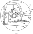
- FIG 4 is a schematic structural view of an electrical appliance chamber 112 according to one embodiment of the present invention.
- Figure 6 is a schematic structural view of the electrical appliance chamber 112 according to another embodiment of the present invention.
- the peripheral edge of the radiating antenna 150 may be formed by smooth curves, so as to make the distribution of electromagnetic waves in the cylinder body 110 more uniform, thereby improving the temperature uniformity of the object to be processed.
- a smooth curve refers to a curve of which the first derivative of the curve equation is continuous, which means that the peripheral edge of the radiating antenna 150 has no sharp corner in engineering.
- the heating unit 100 may further include an antenna housing 130 to separate the inner space of the cylinder body 110 into a heating chamber 111 and an electrical appliance chamber 112.
- the object to be processed and the radiating antenna 150 may be respectively disposed in the heating chamber 111 and the electrical appliance chamber 112 to separate the object to be processed from the radiating antenna 150, so as to prevent the radiating antenna 150 from being dirty or damaged by accidental touch.
- the antenna housing 130 may be made of an insulating material, so that the electromagnetic waves generated by the radiating antenna 150 may pass through the antenna housing 130 to heat the object to be processed. Further, the antenna housing 130 may be made of a non-transparent material to reduce the electromagnetic loss of electromagnetic waves at the antenna housing 130, thereby increasing the heating rate of the object to be processed.
- the above-mentioned non-transparent material is a translucent material or an opaque material.
- the non-transparent material may be a PP material, a PC material or an ABS material.
- the antenna housing 130 may also be configured to fix the radiating antenna 150 to simplify the assembly process of the heating unit 100 and facilitate the positioning and installation of the radiating antenna 150.
- the antenna housing 130 may include a clapboard 131 for separating the heating chamber 111 and the electrical appliance chamber 112, and a skirt part 132 fixedly connected with the inner wall of the cylinder body 110, wherein the radiating antenna 150 may be configured to be fixedly connected with the clapboard 131.
- the radiating antenna 150 may be configured to be engaged with the antenna housing 130.
- Figure 5 is a schematic enlarged view of a region B in Figure 4 .
- the radiating antenna 150 may be provided with a plurality of engaging holes 151; the antenna housing 130 may be correspondingly provided with a plurality of buckles 133; and the plurality of buckles 133 are configured to respectively pass through the plurality of engaging holes 151 to be engaged with the radiating antenna 150.
- each of the buckles 133 may be composed of two barbs disposed at an interval and in mirror symmetry.
- each of the buckles 133 may be composed of a fixing part perpendicular to the radiating antenna 150 and having a hollow middle part, and an elastic part extending inclining to the fixing part from the inner end edge of the fixing part and toward the antenna.
- the radiating antenna 150 may be configured to be fixed to the antenna housing 130 through an electroplating process.
- the antenna housing 130 may further include a plurality of reinforcing ribs, and the reinforcing ribs are configured to connect the clapboard 131 and the skirt part 132 so as to improve the structural strength of the antenna housing 130.
- the antenna housing 130 may be disposed at the bottom of the cylinder body 110 to avoid the damage to the antenna housing 130 due to the fact that a user places an object to be processed with an excessive height.
- the radiating antenna 150 may be horizontally fixed on the lower surface of the clapboard 131.
- the radiating antenna 150 may be disposed at the height of 1/3 to 1/2, such as 1/3, 2/5 or 1/2, of the cylinder body 110, so that the volume of the heating chamber 111 is relatively large, and meanwhile, the electromagnetic waves in the heating chamber 111 have a relatively high energy density so as to make the object to be processed heated quickly.
- FIG 3 is a schematic enlarged view of a region A in Figure 2 .
- the heating unit 100 may further include a signal processing and measurement and control circuit 170.
- the signal processing and measurement and control circuit 170 may include a detection unit 171, a control unit 172 and a matching unit 173.
- the detection unit 171 may be connected in series between the electromagnetic generating module 161 and the radiating antenna 150, and is configured to detect in real time the specific parameters of incident wave signals and reflected wave signals passing through the detection unit.
- the control unit 172 may be configured to acquire the specific parameters from the detection unit 171, and calculate the power of incident waves and reflected waves according to the specific parameters.
- the specific parameters may be voltage values and/or current values.
- the control unit 172 may further calculate an electromagnetic wave absorption rate of the object to be processed according to the power of incident waves and reflected waves, compare the electromagnetic wave absorption rate with a preset absorption threshold, and send an adjusting command to the matching unit 173 when the electromagnetic wave absorption rate is less than the preset absorption threshold.
- the preset absorption threshold may be 60% to 80%, such as 60%, 70% or 80%.
- the matching unit 173 may be connected in series between the electromagnetic generating module 161 and the radiating antenna 150, and is configured to adjust a load impedance of the electromagnetic generating module 161 according to an adjusting command of the control unit 172, so as to improve the matching degree between the output impedance and the load impedance of the electromagnetic generating module 161, so that when foods with different fixed attributes (such as type, weight and volume) are placed in the heating chamber 111, or during the temperature change of the foods, relatively more electromagnetic wave energy is radiated in the heating chamber 111, thereby increasing the heating rate.
- different fixed attributes such as type, weight and volume
- the heating unit 100 may be used for thawing.
- the control unit 172 may also be configured to calculate an imaginary part change rate of a dielectric coefficient of the object to be processed according to the power of incident waves and reflected waves, compare the imaginary part change rate with a preset change threshold, and send a stop command to the electromagnetic generating module 161 when the imaginary part change rate of the dielectric coefficient of the object to be processed is greater than or equal to the preset change threshold, so that the electromagnetic generating module 161 stops working, and the thawing program is terminated.
- the preset change threshold may be obtained by testing the imaginary part change rate of the dielectric coefficient of foods with different fixed attributes at -3°C to 0°C, so that the foods have good shear strength. For example, when the object to be processed is raw beef, the preset change threshold may be set to be 2.
- the control unit 172 may also be configured to receive a user command and control the electromagnetic generating module 161 to start working according to the user command, wherein the control unit 172 is configured to be electrically connected with the power supply module 162 to obtain electric energy from the power supply module 162 and to be always in a standby state.
- the signal processing and measurement and control circuit 170 may be integrated on a circuit board and disposed in parallel with the radiating antenna 150 to facilitate the electrical connection between the radiating antenna 150 and a matching module.
- the antenna housing 130 and the cylinder body 110 may be provided with heat dissipation holes 190 respectively in positions corresponding to the matching unit 173, so that the heat generated by the matching unit 173 during working is discharged through the heat dissipation holes 190.
- the signal processing and measurement and control circuit 170 may be disposed on the rear side of the radiating antenna 150.
- the heat dissipation holes 190 may be formed in the rear walls of the antenna housing 130 and the cylinder body 110.
- the metal cylinder body 110 is configured to be grounded to discharge the electric charges thereon, thereby improving the safety of the heating unit 100.
- the heating unit 100 may further include a metal bracket 180.
- the metal bracket 180 may be configured to connect the circuit board and the cylinder body 110 to support the circuit board and discharge the electric charges on the circuit board through the cylinder body 110.
- the metal bracket 180 may be composed of two parts perpendicular to each other.
- the present invention provides a refrigerating and freezing device 200.
- Figure 8 is a schematic structural view of a refrigerating and freezing device 200 according to the present invention.
- the refrigerating and freezing device 200 may include a cabinet defining at least one storage compartment, at least one cabinet door configured to respectively open and close the at least one storage compartment, and a refrigerating system configured to provide cooling capacity to the at least one storage compartment.
- the cylinder body of the heating unit 100 is disposed in one storage compartment.
- at least one means one, two, or more than two.
- a refrigerating compartment 221 there are two storage compartments, namely a refrigerating compartment 221 and a freezing compartment 222 disposed under the refrigerating compartment 221.
- the cylinder body of the heating unit 100 is disposed in the freezing compartment 222.
- the refrigerating system includes a compressor 241, a condenser 243, an evaporator 242, a refrigerating fan 244 for blowing the cooling capacity generated by the evaporator 242 into the freezing compartment 222, and a heat dissipation fan 245 for heat dissipation of the condenser 243.
- the cabinet includes an inner liner 220, a shell 230 and an insulating layer 210 disposed between the inner liner 220 and the shell 230.
- the shell 230 includes two side panels respectively located on two lateral sides of the insulating layer 210, bottom steel 231 located at the bottom of the insulating layer 210, and a back plate located at the rear part of the insulating layer 210.
- the refrigerating and freezing device 200 further includes a power line (not shown in the figure) for receiving commercial power, so as to supply power to the heating unit 100 and the refrigerating system.
- the power line includes a grounding wire which is connected with a ground wire in the commercial power and is conductively connected with the bottom steel 231, so as to prevent the electric leakage of the refrigerating and freezing device 200.
- Figure 9 is a schematic structural view of a compressor chamber 2311 in Figure 8 .
- the bottom steel 231 defines a compressor chamber 2311, and the compressor 241, the condenser 243 and the heat dissipation fan 245 are disposed in the compressor chamber 2311.
- Two lateral side walls of the compressor chamber 2311 may be respectively provided with an air vent 2312 to allow ambient air to enter the compressor chamber 2311 to dissipate heat from the condenser 243 and the compressor 241.
- the electromagnetic generating module 161 is disposed in the compressor chamber 2311 to use the heat dissipation fan 245 to dissipate heat from the electromagnetic generating module 161.
- a heat dissipation fin 270 may also be disposed in the compressor chamber 2311 and is disposed above the electromagnetic generating module 161 and thermally connected with the electromagnetic generating module 161, so as to increase the heat dissipation area of the electromagnetic generating module 161 and improve the heat dissipation efficiency of the electromagnetic generating module 161.
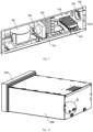
- Figure 10 is a schematic structural view of a part of a heating unit located in a storage compartment when viewed from the rear to the front.
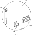
- Figure 11 is a schematic enlarged view of a region D in Figure 10 .
- a part of the metal bracket 180 may be disposed at the rear part of the circuit board and extend vertically along a lateral direction, and it is provided with two wiring ports, so that a wiring terminal 175 of the detection unit 171 (or the matching unit 173) and a wiring terminal 174 of the control unit 172 respectively extend out from a wiring port, and are electrically connected with the electromagnetic generating module 161 through a signal transmission wire 251.
- the cylinder body 110 is conductively connected with the bottom steel 231 through a lead wire 252 to guide the electric charges thereon to the bottom steel 231 so as to avoid potential safety hazards.
- the signal transmission wire 251 and the lead wire 252 are disposed in the insulating layer 210 in advance, and pass through the inner liner 220 and the bottom steel 231 to respectively reserve wiring terminals in the freezing compartment 222 and the compressor chamber 2311, so that the signal transmission wire 251 and the lead wire 252 are routed together so as to save the assembly cost.
- Two wiring terminals of the lead wire 252 are conductively connected with the cylinder body 110 and the bottom steel 231 respectively by a fastener 261 and a fastener 262. During assembly, a stable and reliable conductive connection of the lead wire 252 with the cylinder body 110 and the bottom steel 231 are realized only by tightening the fasteners.
Landscapes
- Engineering & Computer Science (AREA)
- Physics & Mathematics (AREA)
- Chemical & Material Sciences (AREA)
- Thermal Sciences (AREA)
- Combustion & Propulsion (AREA)
- Mechanical Engineering (AREA)
- General Engineering & Computer Science (AREA)
- Electromagnetism (AREA)
- Devices That Are Associated With Refrigeration Equipment (AREA)
- Life Sciences & Earth Sciences (AREA)
- Wood Science & Technology (AREA)
- Zoology (AREA)
- Food Science & Technology (AREA)
- Polymers & Plastics (AREA)
Description
- The present invention relates to a refrigerating and freezing device with an electromagnetic wave heating unit.
- In the freezing process of food, the quality of the food is maintained, but the frozen food needs to be thawed before processing or eating. In order to facilitate users freezing and thawing the food, in the prior art, the food is generally thawed by an electromagnetic wave device.
- However, when the electromagnetic wave device works, a high-voltage electromagnetic field is formed in a chamber of the electromagnetic wave device, which easily causes potential safety hazards. By comprehensive consideration, a refrigerating and freezing device, which has an electromagnetic wave heating unit, with a high safety coefficient is required in design.
-
WO 2018/225597 A1 discloses a refrigerator comprising a determination unit that determines timing of completion by detecting either the storage time or a change in the physical property of a stored item, and a notification unit that notifies a user of completion. -
CN 109000408 A teaches a refrigerator with a quick thawing function. In particular it provides a refrigerator including a box body and a thawing device defining a refrigerating compartment, a temperature changing compartment and a freezing compartment. -
JPS 57210278 (A - An objective of the present invention is to provide a refrigerating and freezing device with a high safety coefficient.
- A further objective of the present invention is to improve the heating efficiency.
- A refrigerating and freezing device, comprising:
- a cabinet, defining at least one storage compartment;
- a refrigerating system, configured to provide cooling capacity to the at least one storage compartment; and
- a heating unit (100), wherein the heating unit (100) comprises:
- a metal cylinder body (110), disposed in one of the storage compartments and provided with a pick-and-place opening;
- a door body (120), disposed at the pick-and-place opening and configured to open and close the pick-and-place opening; and
- an electromagnetic generating system (161), at least a part of which is disposed in the cylinder body (110) or accessed into the cylinder body (110), so as to generate electromagnetic waves in the cylinder body (110) to heat an object to be processed, wherein the cylinder body (110) is configured to be grounded, wherein
- the cabinet comprises an inner liner (220), a shell (230) and an insulating layer (210) disposed between the inner liner (220) and the shell (230), and the shell (230) comprises bottom steel (231) disposed at a bottom of the insulating layer (210); and the refrigerating and freezing device further comprises:
- a power line, configured to receive commercial power and supply power to the refrigerating system, and the power line comprising a grounding wire connected with a ground wire in the commercial power and conductively connected with the bottom steel (231); and
- a lead wire (252), one end of which is configured to be conductively connected with the metal cylinder body (110), and the other end of which is configured to be conductively connected with the bottom steel (231), wherein
- the bottom steel (231) defines a compressor chamber (2311) comprising a compressor (241) of the refrigerating system; and
- the lead wire (252) is disposed in the insulating layer (210) in advance, and passes through the inner liner (220) and the bottom steel (231) to reserve wiring terminals (174, 175) respectively in the storage compartment where the cylinder body (110) is located and the compressor chamber (2311), wherein the electromagnetic generating system (161) comprises:
- an electromagnetic generating module (161), configured to generate an electromagnetic wave signal; and
- a radiating antenna (150), disposed in the cylinder body (110) and electrically connected with the electromagnetic generating module (161) to generate electromagnetic waves of a corresponding frequency in the cylinder body (110) according to the electromagnetic wave signal, wherein
- the electromagnetic generating module (161) is disposed in the compressor chamber (2311) to facilitate heat dissipation of the electromagnetic generating module (161);
- the refrigerating and freezing device further comprising a condenser (243), an evaporator (242), a refrigerating fan (244) for blowing the cooling capacity generated by the evaporator (242) into a freezing compartment (222), and a heat dissipation fan (245) for heat dissipation of the condenser (243), wherein the electromagnetic generating module (161) is disposed in the compressor chamber (2311) to use the heat dissipation fan (245) to dissipate heat from the electromagnetic generating module (161).
- According to the following detailed descriptions of specific embodiments of the present invention in conjunction with the drawings, those skilled in the art will more clearly understand the above and other objectives, advantages and features of the present invention.
- Some specific embodiments of the present invention are described in detail below with reference to the drawings by way of example and not limitation. The same reference numerals in the drawings indicate the same or similar components or parts. Those skilled in the art should understand that these drawings are not necessarily drawn in scale. In figures:
-
Figure 1 is a schematic structural view of a heating unit according to one embodiment of the present invention. -
Figure 2 is a schematic cross-sectional view of the heating unit as shown inFigure 1 , wherein an electromagnetic generating module and a power supply module are omitted. -
Figure 3 is a schematic enlarged view of a region A inFigure 2 . -
Figure 4 is a schematic structural view of an electrical appliance chamber according to one embodiment of the present invention. -
Figure 5 is a schematic enlarged view of a region B inFigure 4 . -
Figure 6 is a schematic structural view of an electrical appliance chamber according to another embodiment of the present invention. -
Figure 7 is a schematic enlarged view of a region C inFigure 6 . -
Figure 8 is a schematic structural view of a refrigerating and freezing device according to one embodiment of the present invention. -
Figure 9 is a schematic structural view of a compressor chamber inFigure 8 . -
Figure 10 is a schematic structural view of a part of a heating unit located in a storage compartment when viewed from the rear to the front. -
Figure 11 is a schematic enlarged view of a region D inFigure 10 . - The invention is defined by the claims.
Figure 1 is a schematic structural view of aheating unit 100 according to one embodiment of the present invention.Figure 2 is a schematic cross-sectional view of theheating unit 100 as shown inFigure 1 , wherein anelectromagnetic generating module 161 and apower supply module 162 are omitted. Referring toFigure 1 andFigure 2 , theheating unit 100 may include acylinder body 110, adoor body 120 and an electromagnetic generating system. - The
cylinder body 110 is configured to place an object to be processed, and a front wall or a top wall thereof may be provided with a pick-and-place opening for picking and placing the object to be processed. - The
door body 120 is installed together with thecylinder body 110 by an appropriate method, such as a sliding rail connection, a hinged connection, etc., and is configured to open and close the pick-and-place opening. In an illustrated embodiment, theheating unit 100 also includes adrawer 140 for carrying the object to be processed; a front end plate of thedrawer 140 is configured to be fixedly connected with thedoor body 120, and two lateral side plates of the drawer are movably connected with thecylinder body 110 by sliding rails. - The electromagnetic generating system is disposed such that at least a part thereof is disposed in the
cylinder body 110 or accessed into thecylinder body 110, so as to generate electromagnetic waves in thecylinder body 110 to heat the object to be processed in thecylinder body 110. - The
cylinder body 110 and thedoor body 120 are respectively provided with electromagnetic shielding features, so that thedoor body 120 is conductively connected with thecylinder body 110 when the door body is in a closed state, so as to prevent electromagnetic leakage. - The electromagnetic generating system includes an
electromagnetic generating module 161, apower supply module 162 and aradiating antenna 150. - The
power supply module 162 is configured to be electrically connected with theelectromagnetic generating module 161 to provide electric energy to theelectromagnetic generating module 161, so that theelectromagnetic generating module 161 generates electromagnetic wave signals. Theradiating antenna 150 may be disposed in thecylinder body 110 and is electrically connected with theelectromagnetic generating module 161 to generate electromagnetic waves of corresponding frequencies according to the electromagnetic wave signals, so as to heat the object to be processed in thecylinder body 110. - The
cylinder body 110 is made of metals to serve as a receiving pole to receive electromagnetic waves generated by theradiating antenna 150. In some other embodiments, a receiving pole plate may be disposed on the top wall of thecylinder body 110 to receive electromagnetic waves generated by theradiating antenna 150. -
Figure 4 is a schematic structural view of anelectrical appliance chamber 112 according to one embodiment of the present invention.Figure 6 is a schematic structural view of theelectrical appliance chamber 112 according to another embodiment of the present invention. Referring toFigure 4 andFigure 6 , the peripheral edge of theradiating antenna 150 may be formed by smooth curves, so as to make the distribution of electromagnetic waves in thecylinder body 110 more uniform, thereby improving the temperature uniformity of the object to be processed. A smooth curve refers to a curve of which the first derivative of the curve equation is continuous, which means that the peripheral edge of the radiatingantenna 150 has no sharp corner in engineering. - Referring to
Figure 2 andFigure 4 , theheating unit 100 may further include anantenna housing 130 to separate the inner space of thecylinder body 110 into aheating chamber 111 and anelectrical appliance chamber 112. The object to be processed and the radiatingantenna 150 may be respectively disposed in theheating chamber 111 and theelectrical appliance chamber 112 to separate the object to be processed from the radiatingantenna 150, so as to prevent the radiatingantenna 150 from being dirty or damaged by accidental touch. - In some embodiments, the
antenna housing 130 may be made of an insulating material, so that the electromagnetic waves generated by the radiatingantenna 150 may pass through theantenna housing 130 to heat the object to be processed. Further, theantenna housing 130 may be made of a non-transparent material to reduce the electromagnetic loss of electromagnetic waves at theantenna housing 130, thereby increasing the heating rate of the object to be processed. The above-mentioned non-transparent material is a translucent material or an opaque material. The non-transparent material may be a PP material, a PC material or an ABS material. - The
antenna housing 130 may also be configured to fix the radiatingantenna 150 to simplify the assembly process of theheating unit 100 and facilitate the positioning and installation of the radiatingantenna 150. Specifically, theantenna housing 130 may include aclapboard 131 for separating theheating chamber 111 and theelectrical appliance chamber 112, and askirt part 132 fixedly connected with the inner wall of thecylinder body 110, wherein the radiatingantenna 150 may be configured to be fixedly connected with theclapboard 131. - In some embodiments, the radiating
antenna 150 may be configured to be engaged with theantenna housing 130.Figure 5 is a schematic enlarged view of a region B inFigure 4 . Referring toFigure 5 , the radiatingantenna 150 may be provided with a plurality of engagingholes 151; theantenna housing 130 may be correspondingly provided with a plurality ofbuckles 133; and the plurality ofbuckles 133 are configured to respectively pass through the plurality of engagingholes 151 to be engaged with the radiatingantenna 150. - In one embodiment of the present invention, each of the
buckles 133 may be composed of two barbs disposed at an interval and in mirror symmetry. -
Figure 7 is a schematic enlarged view of a region C inFigure 6 . Referring toFigure 7 , in another embodiment of the present invention, each of thebuckles 133 may be composed of a fixing part perpendicular to the radiatingantenna 150 and having a hollow middle part, and an elastic part extending inclining to the fixing part from the inner end edge of the fixing part and toward the antenna. - In some other embodiments, the radiating
antenna 150 may be configured to be fixed to theantenna housing 130 through an electroplating process. - The
antenna housing 130 may further include a plurality of reinforcing ribs, and the reinforcing ribs are configured to connect theclapboard 131 and theskirt part 132 so as to improve the structural strength of theantenna housing 130. - In some embodiments, the
antenna housing 130 may be disposed at the bottom of thecylinder body 110 to avoid the damage to theantenna housing 130 due to the fact that a user places an object to be processed with an excessive height. The radiatingantenna 150 may be horizontally fixed on the lower surface of theclapboard 131. - The radiating
antenna 150 may be disposed at the height of 1/3 to 1/2, such as 1/3, 2/5 or 1/2, of thecylinder body 110, so that the volume of theheating chamber 111 is relatively large, and meanwhile, the electromagnetic waves in theheating chamber 111 have a relatively high energy density so as to make the object to be processed heated quickly. -
Figure 3 is a schematic enlarged view of a region A inFigure 2 . referring toFigure 1 to Figure 3 , theheating unit 100 may further include a signal processing and measurement andcontrol circuit 170. Specifically, the signal processing and measurement andcontrol circuit 170 may include adetection unit 171, acontrol unit 172 and amatching unit 173. - The
detection unit 171 may be connected in series between theelectromagnetic generating module 161 and the radiatingantenna 150, and is configured to detect in real time the specific parameters of incident wave signals and reflected wave signals passing through the detection unit. - The
control unit 172 may be configured to acquire the specific parameters from thedetection unit 171, and calculate the power of incident waves and reflected waves according to the specific parameters. In the present invention, the specific parameters may be voltage values and/or current values. - The
control unit 172 may further calculate an electromagnetic wave absorption rate of the object to be processed according to the power of incident waves and reflected waves, compare the electromagnetic wave absorption rate with a preset absorption threshold, and send an adjusting command to thematching unit 173 when the electromagnetic wave absorption rate is less than the preset absorption threshold. The preset absorption threshold may be 60% to 80%, such as 60%, 70% or 80%. - The
matching unit 173 may be connected in series between theelectromagnetic generating module 161 and the radiatingantenna 150, and is configured to adjust a load impedance of theelectromagnetic generating module 161 according to an adjusting command of thecontrol unit 172, so as to improve the matching degree between the output impedance and the load impedance of theelectromagnetic generating module 161, so that when foods with different fixed attributes (such as type, weight and volume) are placed in theheating chamber 111, or during the temperature change of the foods, relatively more electromagnetic wave energy is radiated in theheating chamber 111, thereby increasing the heating rate. - In some embodiments, the
heating unit 100 may be used for thawing. Thecontrol unit 172 may also be configured to calculate an imaginary part change rate of a dielectric coefficient of the object to be processed according to the power of incident waves and reflected waves, compare the imaginary part change rate with a preset change threshold, and send a stop command to theelectromagnetic generating module 161 when the imaginary part change rate of the dielectric coefficient of the object to be processed is greater than or equal to the preset change threshold, so that theelectromagnetic generating module 161 stops working, and the thawing program is terminated. - The preset change threshold may be obtained by testing the imaginary part change rate of the dielectric coefficient of foods with different fixed attributes at -3°C to 0°C, so that the foods have good shear strength. For example, when the object to be processed is raw beef, the preset change threshold may be set to be 2.
- The
control unit 172 may also be configured to receive a user command and control theelectromagnetic generating module 161 to start working according to the user command, wherein thecontrol unit 172 is configured to be electrically connected with thepower supply module 162 to obtain electric energy from thepower supply module 162 and to be always in a standby state. - In some embodiments, the signal processing and measurement and
control circuit 170 may be integrated on a circuit board and disposed in parallel with the radiatingantenna 150 to facilitate the electrical connection between the radiatingantenna 150 and a matching module. - The
antenna housing 130 and thecylinder body 110 may be provided with heat dissipation holes 190 respectively in positions corresponding to thematching unit 173, so that the heat generated by thematching unit 173 during working is discharged through the heat dissipation holes 190. In some embodiments, the signal processing and measurement andcontrol circuit 170 may be disposed on the rear side of the radiatingantenna 150. The heat dissipation holes 190 may be formed in the rear walls of theantenna housing 130 and thecylinder body 110. - The
metal cylinder body 110 is configured to be grounded to discharge the electric charges thereon, thereby improving the safety of theheating unit 100. - The
heating unit 100 may further include ametal bracket 180. Themetal bracket 180 may be configured to connect the circuit board and thecylinder body 110 to support the circuit board and discharge the electric charges on the circuit board through thecylinder body 110. In some embodiments, themetal bracket 180 may be composed of two parts perpendicular to each other. - Based on the
heating unit 100 according to any one of the above embodiments, the present invention provides a refrigerating and freezingdevice 200.Figure 8 is a schematic structural view of a refrigerating and freezingdevice 200 according to the present invention. Referring toFigure 8 , the refrigerating and freezingdevice 200 may include a cabinet defining at least one storage compartment, at least one cabinet door configured to respectively open and close the at least one storage compartment, and a refrigerating system configured to provide cooling capacity to the at least one storage compartment. The cylinder body of theheating unit 100 is disposed in one storage compartment. In the present invention, at least one means one, two, or more than two. - In an illustrated embodiment, there are two storage compartments, namely a
refrigerating compartment 221 and a freezingcompartment 222 disposed under therefrigerating compartment 221. The cylinder body of theheating unit 100 is disposed in the freezingcompartment 222. - The refrigerating system includes a
compressor 241, acondenser 243, anevaporator 242, a refrigeratingfan 244 for blowing the cooling capacity generated by theevaporator 242 into the freezingcompartment 222, and aheat dissipation fan 245 for heat dissipation of thecondenser 243. - The cabinet includes an
inner liner 220, ashell 230 and an insulatinglayer 210 disposed between theinner liner 220 and theshell 230. Theshell 230 includes two side panels respectively located on two lateral sides of the insulatinglayer 210,bottom steel 231 located at the bottom of the insulatinglayer 210, and a back plate located at the rear part of the insulatinglayer 210. - The refrigerating and freezing
device 200 further includes a power line (not shown in the figure) for receiving commercial power, so as to supply power to theheating unit 100 and the refrigerating system. The power line includes a grounding wire which is connected with a ground wire in the commercial power and is conductively connected with thebottom steel 231, so as to prevent the electric leakage of the refrigerating and freezingdevice 200. -
Figure 9 is a schematic structural view of acompressor chamber 2311 inFigure 8 . Referring toFigure 9 , thebottom steel 231 defines acompressor chamber 2311, and thecompressor 241, thecondenser 243 and theheat dissipation fan 245 are disposed in thecompressor chamber 2311. Two lateral side walls of thecompressor chamber 2311 may be respectively provided with anair vent 2312 to allow ambient air to enter thecompressor chamber 2311 to dissipate heat from thecondenser 243 and thecompressor 241. - According to the invention, the
electromagnetic generating module 161 is disposed in thecompressor chamber 2311 to use theheat dissipation fan 245 to dissipate heat from theelectromagnetic generating module 161. Aheat dissipation fin 270 may also be disposed in thecompressor chamber 2311 and is disposed above theelectromagnetic generating module 161 and thermally connected with theelectromagnetic generating module 161, so as to increase the heat dissipation area of theelectromagnetic generating module 161 and improve the heat dissipation efficiency of theelectromagnetic generating module 161. -
Figure 10 is a schematic structural view of a part of a heating unit located in a storage compartment when viewed from the rear to the front.Figure 11 is a schematic enlarged view of a region D inFigure 10 . Referring toFigure 4 ,Figure 10 andFigure 11 , a part of themetal bracket 180 may be disposed at the rear part of the circuit board and extend vertically along a lateral direction, and it is provided with two wiring ports, so that awiring terminal 175 of the detection unit 171 (or the matching unit 173) and awiring terminal 174 of thecontrol unit 172 respectively extend out from a wiring port, and are electrically connected with theelectromagnetic generating module 161 through asignal transmission wire 251. - Specifically, the
cylinder body 110 is conductively connected with thebottom steel 231 through alead wire 252 to guide the electric charges thereon to thebottom steel 231 so as to avoid potential safety hazards. - The
signal transmission wire 251 and thelead wire 252 are disposed in the insulatinglayer 210 in advance, and pass through theinner liner 220 and thebottom steel 231 to respectively reserve wiring terminals in the freezingcompartment 222 and thecompressor chamber 2311, so that thesignal transmission wire 251 and thelead wire 252 are routed together so as to save the assembly cost. - Two wiring terminals of the
lead wire 252 are conductively connected with thecylinder body 110 and thebottom steel 231 respectively by afastener 261 and afastener 262. During assembly, a stable and reliable conductive connection of thelead wire 252 with thecylinder body 110 and thebottom steel 231 are realized only by tightening the fasteners.
Claims (6)
- A refrigerating and freezing device, comprising:a cabinet, defining at least one storage compartment;a refrigerating system, configured to provide cooling capacity to the at least one storage compartment; anda heating unit (100), wherein the heating unit (100) comprises:a metal cylinder body (110), disposed in one of the storage compartments and provided with a pick-and-place opening;a door body (120), disposed at the pick-and-place opening and configured to open and close the pick-and-place opening; andan electromagnetic generating system (161), at least a part of which is disposed in the cylinder body (110) or accessed into the cylinder body (110), so as to generate electromagnetic waves in the cylinder body (110) to heat an object to be processed, wherein the cylinder body (110) is configured to be grounded, whereinthe cabinet comprises an inner liner (220), a shell (230) and an insulating layer (210) disposed between the inner liner (220) and the shell (230), and the shell (230) comprises bottom steel (231) disposed at a bottom of the insulating layer (210); and the refrigerating and freezing device further comprises:a power line, configured to receive commercial power and supply power to the refrigerating system, and the power line comprising a grounding wire connected with a ground wire in the commercial power and conductively connected with the bottom steel (231); anda lead wire (252), one end of which is configured to be conductively connected with the metal cylinder body (110), and the other end of which is configured to be conductively connected with the bottom steel (231), whereinthe bottom steel (231) defines a compressor chamber (2311) comprising a compressor (241) of the refrigerating system; andthe lead wire (252) is disposed in the insulating layer (210) in advance, and passes through the inner liner (220) and the bottom steel (231) to reserve wiring terminals (174, 175) respectively in the storage compartment where the cylinder body (110) is located and the compressor chamber (2311), wherein the electromagnetic generating system (161) comprises:an electromagnetic generating module (161), configured to generate an electromagnetic wave signal; anda radiating antenna (150), disposed in the cylinder body (110) and electrically connected with the electromagnetic generating module (161) to generate electromagnetic waves of a corresponding frequency in the cylinder body (110) according to the electromagnetic wave signal, whereinthe electromagnetic generating module (161) is disposed in the compressor chamber (2311) to facilitate heat dissipation of the electromagnetic generating module (161);the refrigerating and freezing device further comprising a condenser (243), an evaporator (242), a refrigerating fan (244) for blowing the cooling capacity generated by the evaporator (242) into a freezing compartment (222), and a heat dissipation fan (245) for heat dissipation of the condenser (243), wherein the electromagnetic generating module (161) is disposed in the compressor chamber (2311) to use the heat dissipation fan (245) to dissipate heat from the electromagnetic generating module (161).
- The refrigerating and freezing device according to claim 1, wherein the wiring terminals (174, 175) are configured to be respectively fixed to and conductively connected with the cylinder body (110) and the bottom steel (231) by fasteners.
- The refrigerating and freezing device according to claim 1, further comprising:a heat dissipation fin (270), configured to be thermally connected with the electromagnetic generating module (161) to increase a heat dissipation area of the electromagnetic generating module (161); andtwo lateral side walls of the compressor chamber (2311) being respectively provided with an air vent (2312) to allow ambient air to enter the compressor chamber (2311) and exchange heat with the electromagnetic generating module (161) and the heat dissipation fin (270).
- The refrigerating and freezing device according to claim 1, further comprising:
a signal processing and measurement and control circuit, comprising:a detection unit (171), connected in series between the electromagnetic generating module (161) and the radiating antenna (150), and configured to detect specific parameters of an incident wave signal and a reflected wave signal passing through the detection unit (171);a control unit (172), configured to calculate an electromagnetic wave absorption rate of the object to be processed according to the specific parameters; anda matching unit (173), connected in series between the electromagnetic generating module (161) and the radiating antenna (150), and configured to adjust a load impedance of the electromagnetic generating module (161) according to the electromagnetic wave absorption rate. - The refrigerating and freezing device according to claim 4, wherein
the signal processing and measurement and control circuit is integrated on a circuit board, and the circuit board is configured to be conductively connected with the cylinder body (110). - The refrigerating and freezing device according to claim 5, wherein
the circuit board and the radiating antenna (150) are disposed in parallel to facilitate an electrical connection between the signal processing and measurement and control circuit and the radiating antenna (150).
Applications Claiming Priority (2)
| Application Number | Priority Date | Filing Date | Title |
|---|---|---|---|
| CN201920013449.XU CN209893774U (en) | 2019-01-04 | 2019-01-04 | Refrigerating and freezing device |
| PCT/CN2019/124873 WO2020140722A1 (en) | 2019-01-04 | 2019-12-12 | Refrigeration and freezing apparatus |
Publications (3)
| Publication Number | Publication Date |
|---|---|
| EP3907452A1 EP3907452A1 (en) | 2021-11-10 |
| EP3907452A4 EP3907452A4 (en) | 2022-03-02 |
| EP3907452B1 true EP3907452B1 (en) | 2023-04-12 |
Family
ID=69015676
Family Applications (1)
| Application Number | Title | Priority Date | Filing Date |
|---|---|---|---|
| EP19906611.9A Active EP3907452B1 (en) | 2019-01-04 | 2019-12-12 | Refrigeration and freezing apparatus |
Country Status (5)
| Country | Link |
|---|---|
| US (1) | US12298074B2 (en) |
| EP (1) | EP3907452B1 (en) |
| CN (1) | CN209893774U (en) |
| AU (1) | AU2019418577B2 (en) |
| WO (1) | WO2020140722A1 (en) |
Families Citing this family (4)
| Publication number | Priority date | Publication date | Assignee | Title |
|---|---|---|---|---|
| CN209893774U (en) * | 2019-01-04 | 2020-01-03 | 青岛海尔股份有限公司 | Refrigerating and freezing device |
| CN111473593A (en) * | 2019-01-23 | 2020-07-31 | 青岛海尔股份有限公司 | Heating device and refrigerator |
| CN111473594B (en) * | 2019-01-23 | 2025-02-28 | 海尔智家股份有限公司 | Heating device and refrigerator |
| CN115143675B (en) * | 2021-03-31 | 2023-11-14 | 青岛海尔电冰箱有限公司 | Refrigerating and freezing device |
Citations (2)
| Publication number | Priority date | Publication date | Assignee | Title |
|---|---|---|---|---|
| DE3149410A1 (en) * | 1980-12-15 | 1982-07-22 | Linde Ag, 6200 Wiesbaden | Vending chest freezer |
| CN204063776U (en) * | 2014-08-15 | 2014-12-31 | 合肥美菱股份有限公司 | A kind of leakage protection structure of refrigerator heater |
Family Cites Families (68)
| Publication number | Priority date | Publication date | Assignee | Title |
|---|---|---|---|---|
| US4296298A (en) * | 1978-06-12 | 1981-10-20 | Raytheon Company | Dielectric cooking apparatus |
| US4392357A (en) * | 1981-04-27 | 1983-07-12 | Emhart Industries, Inc. | Method and means controlling defrost cycles of a cooling unit |
| JPS57210278A (en) * | 1981-06-19 | 1982-12-23 | Sanyo Electric Co | Refrigerator |
| TW299950U (en) * | 1992-07-30 | 1997-03-01 | Sharp Kk | Communication means for an electrical device in a refrigerator |
| KR100239514B1 (en) * | 1996-07-29 | 2000-01-15 | 윤종용 | Microwave oven |
| CA2255689C (en) * | 1997-03-17 | 2013-07-09 | Akinori Ito | Method and equipment for treating electrostatic field and electrode used therein |
| JPH10304860A (en) * | 1997-05-08 | 1998-11-17 | Houjiya Houjiya:Kk | Thawing freshness preserver for frozen food |
| KR20030004899A (en) * | 2001-07-07 | 2003-01-15 | 엘지전자 주식회사 | Refrigerator with condenser and backcover in one |
| CN2503634Y (en) * | 2001-09-28 | 2002-07-31 | 廖文庆 | Electromagnetic earthing wire |
| JP2003336855A (en) * | 2002-03-13 | 2003-11-28 | Seibu Kin | Electric carpet cover having field cutoff function, electric carpet having field cutoff function, electric heating bedding cover, and electric heating bedding |
| DE20301800U1 (en) | 2003-02-05 | 2003-04-24 | BSH Bosch und Siemens Hausgeräte GmbH, 81669 München | The refrigerator |
| KR100557099B1 (en) * | 2003-12-09 | 2006-03-03 | 엘지전자 주식회사 | Heat Sink of Built-in Refrigerator |
| SE0402261D0 (en) * | 2004-09-17 | 2004-09-17 | Electrolux Home Prod Corp | Capacitive Sensor System |
| KR101330335B1 (en) | 2007-09-21 | 2013-11-15 | 엘지전자 주식회사 | Supercooling apparatus |
| CN201829940U (en) * | 2010-10-29 | 2011-05-11 | 张伟洁 | Anti-electric leakage circuit for ground wire of electrical appliance |
| US20130160467A1 (en) * | 2011-12-22 | 2013-06-27 | Electrolux Home Products, Inc. | Refrigeration device with a region for storing food items in a generated field |
| KR20130094024A (en) * | 2012-02-15 | 2013-08-23 | 동부대우전자 주식회사 | Defrosting apparatus and defrosting method for refrigerator |
| CN202998534U (en) * | 2012-11-14 | 2013-06-12 | 明达实业(厦门)有限公司 | Electromagnetic field generator circuit structure |
| JP6092027B2 (en) * | 2013-07-12 | 2017-03-08 | 東芝ライフスタイル株式会社 | refrigerator |
| US9942951B2 (en) * | 2014-11-21 | 2018-04-10 | Elwha Llc | Microwave heating element |
| CN108605390B (en) * | 2016-02-17 | 2021-03-12 | 松下电器产业株式会社 | microwave heating device |
| CN106288626A (en) * | 2016-08-29 | 2017-01-04 | 合肥华凌股份有限公司 | A kind of thawing apparatus, refrigerator and unfreezing control method thereof |
| CN106568269B (en) * | 2016-10-24 | 2019-08-27 | 青岛海尔股份有限公司 | refrigerator |
| CN106885399B (en) * | 2017-02-15 | 2019-05-28 | 美的集团股份有限公司 | Cooling Components and Refrigeration Units |
| CN109000418B (en) * | 2017-06-06 | 2020-06-23 | 青岛海尔股份有限公司 | Defrost device and refrigerator having the same |
| CN207095131U (en) * | 2017-06-06 | 2018-03-13 | 青岛海尔股份有限公司 | Refrigerator |
| CN109000400B (en) * | 2017-06-06 | 2020-06-23 | 青岛海尔股份有限公司 | side door refrigerator |
| CN109000403B (en) * | 2017-06-06 | 2020-05-26 | 海尔智家股份有限公司 | Thawing method for thawing device |
| CN207095130U (en) * | 2017-06-06 | 2018-03-13 | 青岛海尔股份有限公司 | Refrigerator |
| CN109000402B (en) * | 2017-06-06 | 2020-05-26 | 青岛海尔股份有限公司 | refrigerator |
| CN109000405B (en) * | 2017-06-06 | 2020-06-23 | 青岛海尔股份有限公司 | Refrigerator with a door |
| CN109000404B (en) * | 2017-06-06 | 2020-06-23 | 青岛海尔股份有限公司 | Refrigerator with a door |
| CN109000396B (en) * | 2017-06-06 | 2020-06-23 | 青岛海尔股份有限公司 | Defrost method for refrigerator and refrigerator |
| CN109000408B (en) * | 2017-06-06 | 2020-06-23 | 青岛海尔股份有限公司 | refrigerator |
| CN207095160U (en) * | 2017-06-06 | 2018-03-13 | 青岛海尔股份有限公司 | Thawing apparatus and the refrigerator with the thawing apparatus |
| CN207081264U (en) * | 2017-06-06 | 2018-03-09 | 青岛海尔股份有限公司 | Refrigerator |
| CN207081265U (en) * | 2017-06-06 | 2018-03-09 | 青岛海尔股份有限公司 | Refrigerator |
| CN109000401B (en) * | 2017-06-06 | 2020-06-23 | 青岛海尔股份有限公司 | Refrigerator with a door |
| WO2018225597A1 (en) * | 2017-06-07 | 2018-12-13 | パナソニックIpマネジメント株式会社 | Refrigerator |
| CN207881331U (en) * | 2017-07-31 | 2018-09-18 | 青岛海尔智能技术研发有限公司 | Thawing apparatus and refrigerator with the thawing apparatus |
| CN207247701U (en) * | 2017-07-31 | 2018-04-17 | 青岛海尔智能技术研发有限公司 | Refrigerator |
| CN207247702U (en) * | 2017-07-31 | 2018-04-17 | 青岛海尔智能技术研发有限公司 | Thawing apparatus and the refrigerator with the thawing apparatus |
| US10917948B2 (en) * | 2017-11-07 | 2021-02-09 | Nxp Usa, Inc. | Apparatus and methods for defrosting operations in an RF heating system |
| CN109990554B (en) * | 2017-12-29 | 2021-02-26 | 海尔智家股份有限公司 | Defrost device and refrigerator having the same |
| CN108266959B (en) * | 2017-12-29 | 2020-06-23 | 青岛海尔股份有限公司 | Heat dissipation control method of refrigerator and refrigerator |
| CN108302891B (en) * | 2017-12-29 | 2020-04-21 | 青岛海尔股份有限公司 | Refrigerator cooling control method and refrigerator |
| CN111919109B (en) * | 2018-04-06 | 2024-10-25 | 松下控股株式会社 | Dielectric constant estimation device and microwave heating device having the same |
| CN109259045A (en) * | 2018-10-19 | 2019-01-25 | 恩智浦美国有限公司 | With the thawing equipment that can relocate electrode |
| JP7607257B2 (en) * | 2018-10-23 | 2024-12-27 | パナソニックIpマネジメント株式会社 | Heating device and refrigerator equipped with heating device |
| CN209897305U (en) * | 2019-01-04 | 2020-01-03 | 青岛海尔股份有限公司 | Heating device and refrigerator with same |
| CN111417226B (en) * | 2019-01-04 | 2025-02-28 | 海尔智家股份有限公司 | Heating device |
| CN209897307U (en) * | 2019-01-04 | 2020-01-03 | 青岛海尔股份有限公司 | Heating device |
| CN111417227B (en) * | 2019-01-04 | 2025-08-05 | 海尔智家股份有限公司 | Heating device |
| CN111417228B (en) * | 2019-01-04 | 2025-02-25 | 海尔智家股份有限公司 | Heating device |
| CN111417231A (en) * | 2019-01-04 | 2020-07-14 | 青岛海尔股份有限公司 | Electromagnetic wave generating system and heating device having the same |
| CN111417230B (en) * | 2019-01-04 | 2025-06-06 | 海尔智家股份有限公司 | Electromagnetic wave generating system and heating device having the same |
| CN209893774U (en) * | 2019-01-04 | 2020-01-03 | 青岛海尔股份有限公司 | Refrigerating and freezing device |
| CN111473593A (en) * | 2019-01-23 | 2020-07-31 | 青岛海尔股份有限公司 | Heating device and refrigerator |
| CN111473594B (en) * | 2019-01-23 | 2025-02-28 | 海尔智家股份有限公司 | Heating device and refrigerator |
| CN209897300U (en) * | 2019-01-28 | 2020-01-03 | 青岛海尔特种电冰箱有限公司 | Heating device and refrigerator with same |
| CN209893782U (en) * | 2019-01-30 | 2020-01-03 | 青岛海尔特种电冰箱有限公司 | Refrigerator and freezer |
| KR102721117B1 (en) * | 2019-04-03 | 2024-10-24 | 엘지전자 주식회사 | Refrigerator |
| JP2021060174A (en) * | 2019-10-09 | 2021-04-15 | パナソニックIpマネジメント株式会社 | refrigerator |
| CN113498225B (en) * | 2020-04-02 | 2025-07-08 | 青岛海尔电冰箱有限公司 | Heating unit and refrigerating and freezing device with same |
| CN213029670U (en) * | 2020-08-04 | 2021-04-23 | 青岛海尔特种电冰箱有限公司 | Heating device |
| CN114076497A (en) * | 2020-08-18 | 2022-02-22 | 博西华电器(江苏)有限公司 | Radio frequency power source equipment, heating device and refrigeration equipment |
| CN213486747U (en) * | 2020-08-20 | 2021-06-22 | 青岛海尔特种制冷电器有限公司 | heating equipment |
| WO2022130915A1 (en) * | 2020-12-14 | 2022-06-23 | 株式会社村田製作所 | Heating electromagnetic wave control body and heating electromagnetic wave control body-mounted product |
-
2019
- 2019-01-04 CN CN201920013449.XU patent/CN209893774U/en active Active
- 2019-12-12 US US17/420,590 patent/US12298074B2/en active Active
- 2019-12-12 EP EP19906611.9A patent/EP3907452B1/en active Active
- 2019-12-12 WO PCT/CN2019/124873 patent/WO2020140722A1/en not_active Ceased
- 2019-12-12 AU AU2019418577A patent/AU2019418577B2/en active Active
Patent Citations (2)
| Publication number | Priority date | Publication date | Assignee | Title |
|---|---|---|---|---|
| DE3149410A1 (en) * | 1980-12-15 | 1982-07-22 | Linde Ag, 6200 Wiesbaden | Vending chest freezer |
| CN204063776U (en) * | 2014-08-15 | 2014-12-31 | 合肥美菱股份有限公司 | A kind of leakage protection structure of refrigerator heater |
Also Published As
| Publication number | Publication date |
|---|---|
| US20220079191A1 (en) | 2022-03-17 |
| AU2019418577B2 (en) | 2022-07-14 |
| EP3907452A4 (en) | 2022-03-02 |
| CN209893774U (en) | 2020-01-03 |
| WO2020140722A1 (en) | 2020-07-09 |
| AU2019418577A1 (en) | 2021-07-22 |
| US12298074B2 (en) | 2025-05-13 |
| EP3907452A1 (en) | 2021-11-10 |
Similar Documents
| Publication | Publication Date | Title |
|---|---|---|
| EP3916326B1 (en) | Refrigeration and freezing apparatus | |
| US12235042B2 (en) | Heating device and refrigerator with heating device | |
| US12513792B2 (en) | Heating device and refrigerator with heating device | |
| CN209893783U (en) | Heating device and refrigerator having the same | |
| US12298074B2 (en) | Refrigerating and freezing device | |
| US12150229B2 (en) | Heating device | |
| EP3910272B1 (en) | Heating apparatus and refrigerator | |
| EP3905848A1 (en) | Heating device | |
| RU2778309C1 (en) | Refrigerating and freezing device | |
| RU2776309C1 (en) | Heating apparatus and refrigerator with a heating apparatus | |
| RU2777607C1 (en) | Refrigerating and freezing device | |
| RU2829350C2 (en) | Refrigerating and freezing device | |
| RU2778872C1 (en) | Heating apparatus and refrigerator with a heating apparatus | |
| CN211120207U (en) | Refrigerator and freezer |
Legal Events
| Date | Code | Title | Description |
|---|---|---|---|
| STAA | Information on the status of an ep patent application or granted ep patent |
Free format text: STATUS: THE INTERNATIONAL PUBLICATION HAS BEEN MADE |
|
| PUAI | Public reference made under article 153(3) epc to a published international application that has entered the european phase |
Free format text: ORIGINAL CODE: 0009012 |
|
| STAA | Information on the status of an ep patent application or granted ep patent |
Free format text: STATUS: REQUEST FOR EXAMINATION WAS MADE |
|
| 17P | Request for examination filed |
Effective date: 20210729 |
|
| AK | Designated contracting states |
Kind code of ref document: A1 Designated state(s): AL AT BE BG CH CY CZ DE DK EE ES FI FR GB GR HR HU IE IS IT LI LT LU LV MC MK MT NL NO PL PT RO RS SE SI SK SM TR |
|
| STAA | Information on the status of an ep patent application or granted ep patent |
Free format text: STATUS: EXAMINATION IS IN PROGRESS |
|
| A4 | Supplementary search report drawn up and despatched |
Effective date: 20220131 |
|
| RIC1 | Information provided on ipc code assigned before grant |
Ipc: F25D 31/00 20060101ALI20220125BHEP Ipc: A23L 3/365 20060101ALI20220125BHEP Ipc: H05B 6/12 20060101ALI20220125BHEP Ipc: F25D 23/12 20060101AFI20220125BHEP |
|
| 17Q | First examination report despatched |
Effective date: 20220211 |
|
| DAV | Request for validation of the european patent (deleted) | ||
| DAX | Request for extension of the european patent (deleted) | ||
| GRAP | Despatch of communication of intention to grant a patent |
Free format text: ORIGINAL CODE: EPIDOSNIGR1 |
|
| STAA | Information on the status of an ep patent application or granted ep patent |
Free format text: STATUS: GRANT OF PATENT IS INTENDED |
|
| INTG | Intention to grant announced |
Effective date: 20221213 |
|
| GRAS | Grant fee paid |
Free format text: ORIGINAL CODE: EPIDOSNIGR3 |
|
| GRAA | (expected) grant |
Free format text: ORIGINAL CODE: 0009210 |
|
| STAA | Information on the status of an ep patent application or granted ep patent |
Free format text: STATUS: THE PATENT HAS BEEN GRANTED |
|
| AK | Designated contracting states |
Kind code of ref document: B1 Designated state(s): AL AT BE BG CH CY CZ DE DK EE ES FI FR GB GR HR HU IE IS IT LI LT LU LV MC MK MT NL NO PL PT RO RS SE SI SK SM TR |
|
| REG | Reference to a national code |
Ref country code: GB Ref legal event code: FG4D |
|
| REG | Reference to a national code |
Ref country code: CH Ref legal event code: EP |
|
| REG | Reference to a national code |
Ref country code: DE Ref legal event code: R096 Ref document number: 602019027584 Country of ref document: DE |
|
| REG | Reference to a national code |
Ref country code: IE Ref legal event code: FG4D |
|
| REG | Reference to a national code |
Ref country code: AT Ref legal event code: REF Ref document number: 1559997 Country of ref document: AT Kind code of ref document: T Effective date: 20230515 |
|
| REG | Reference to a national code |
Ref country code: LT Ref legal event code: MG9D |
|
| REG | Reference to a national code |
Ref country code: NL Ref legal event code: MP Effective date: 20230412 |
|
| REG | Reference to a national code |
Ref country code: AT Ref legal event code: MK05 Ref document number: 1559997 Country of ref document: AT Kind code of ref document: T Effective date: 20230412 |
|
| PG25 | Lapsed in a contracting state [announced via postgrant information from national office to epo] |
Ref country code: NL Free format text: LAPSE BECAUSE OF FAILURE TO SUBMIT A TRANSLATION OF THE DESCRIPTION OR TO PAY THE FEE WITHIN THE PRESCRIBED TIME-LIMIT Effective date: 20230412 |
|
| PG25 | Lapsed in a contracting state [announced via postgrant information from national office to epo] |
Ref country code: SE Free format text: LAPSE BECAUSE OF FAILURE TO SUBMIT A TRANSLATION OF THE DESCRIPTION OR TO PAY THE FEE WITHIN THE PRESCRIBED TIME-LIMIT Effective date: 20230412 Ref country code: PT Free format text: LAPSE BECAUSE OF FAILURE TO SUBMIT A TRANSLATION OF THE DESCRIPTION OR TO PAY THE FEE WITHIN THE PRESCRIBED TIME-LIMIT Effective date: 20230814 Ref country code: NO Free format text: LAPSE BECAUSE OF FAILURE TO SUBMIT A TRANSLATION OF THE DESCRIPTION OR TO PAY THE FEE WITHIN THE PRESCRIBED TIME-LIMIT Effective date: 20230712 Ref country code: ES Free format text: LAPSE BECAUSE OF FAILURE TO SUBMIT A TRANSLATION OF THE DESCRIPTION OR TO PAY THE FEE WITHIN THE PRESCRIBED TIME-LIMIT Effective date: 20230412 Ref country code: AT Free format text: LAPSE BECAUSE OF FAILURE TO SUBMIT A TRANSLATION OF THE DESCRIPTION OR TO PAY THE FEE WITHIN THE PRESCRIBED TIME-LIMIT Effective date: 20230412 |
|
| PG25 | Lapsed in a contracting state [announced via postgrant information from national office to epo] |
Ref country code: RS Free format text: LAPSE BECAUSE OF FAILURE TO SUBMIT A TRANSLATION OF THE DESCRIPTION OR TO PAY THE FEE WITHIN THE PRESCRIBED TIME-LIMIT Effective date: 20230412 Ref country code: PL Free format text: LAPSE BECAUSE OF FAILURE TO SUBMIT A TRANSLATION OF THE DESCRIPTION OR TO PAY THE FEE WITHIN THE PRESCRIBED TIME-LIMIT Effective date: 20230412 Ref country code: LV Free format text: LAPSE BECAUSE OF FAILURE TO SUBMIT A TRANSLATION OF THE DESCRIPTION OR TO PAY THE FEE WITHIN THE PRESCRIBED TIME-LIMIT Effective date: 20230412 Ref country code: LT Free format text: LAPSE BECAUSE OF FAILURE TO SUBMIT A TRANSLATION OF THE DESCRIPTION OR TO PAY THE FEE WITHIN THE PRESCRIBED TIME-LIMIT Effective date: 20230412 Ref country code: IS Free format text: LAPSE BECAUSE OF FAILURE TO SUBMIT A TRANSLATION OF THE DESCRIPTION OR TO PAY THE FEE WITHIN THE PRESCRIBED TIME-LIMIT Effective date: 20230812 Ref country code: HR Free format text: LAPSE BECAUSE OF FAILURE TO SUBMIT A TRANSLATION OF THE DESCRIPTION OR TO PAY THE FEE WITHIN THE PRESCRIBED TIME-LIMIT Effective date: 20230412 Ref country code: GR Free format text: LAPSE BECAUSE OF FAILURE TO SUBMIT A TRANSLATION OF THE DESCRIPTION OR TO PAY THE FEE WITHIN THE PRESCRIBED TIME-LIMIT Effective date: 20230713 Ref country code: AL Free format text: LAPSE BECAUSE OF FAILURE TO SUBMIT A TRANSLATION OF THE DESCRIPTION OR TO PAY THE FEE WITHIN THE PRESCRIBED TIME-LIMIT Effective date: 20230412 |
|
| PG25 | Lapsed in a contracting state [announced via postgrant information from national office to epo] |
Ref country code: FI Free format text: LAPSE BECAUSE OF FAILURE TO SUBMIT A TRANSLATION OF THE DESCRIPTION OR TO PAY THE FEE WITHIN THE PRESCRIBED TIME-LIMIT Effective date: 20230412 |
|
| REG | Reference to a national code |
Ref country code: DE Ref legal event code: R097 Ref document number: 602019027584 Country of ref document: DE |
|
| PG25 | Lapsed in a contracting state [announced via postgrant information from national office to epo] |
Ref country code: SK Free format text: LAPSE BECAUSE OF FAILURE TO SUBMIT A TRANSLATION OF THE DESCRIPTION OR TO PAY THE FEE WITHIN THE PRESCRIBED TIME-LIMIT Effective date: 20230412 |
|
| PG25 | Lapsed in a contracting state [announced via postgrant information from national office to epo] |
Ref country code: SM Free format text: LAPSE BECAUSE OF FAILURE TO SUBMIT A TRANSLATION OF THE DESCRIPTION OR TO PAY THE FEE WITHIN THE PRESCRIBED TIME-LIMIT Effective date: 20230412 Ref country code: SK Free format text: LAPSE BECAUSE OF FAILURE TO SUBMIT A TRANSLATION OF THE DESCRIPTION OR TO PAY THE FEE WITHIN THE PRESCRIBED TIME-LIMIT Effective date: 20230412 Ref country code: RO Free format text: LAPSE BECAUSE OF FAILURE TO SUBMIT A TRANSLATION OF THE DESCRIPTION OR TO PAY THE FEE WITHIN THE PRESCRIBED TIME-LIMIT Effective date: 20230412 Ref country code: EE Free format text: LAPSE BECAUSE OF FAILURE TO SUBMIT A TRANSLATION OF THE DESCRIPTION OR TO PAY THE FEE WITHIN THE PRESCRIBED TIME-LIMIT Effective date: 20230412 Ref country code: DK Free format text: LAPSE BECAUSE OF FAILURE TO SUBMIT A TRANSLATION OF THE DESCRIPTION OR TO PAY THE FEE WITHIN THE PRESCRIBED TIME-LIMIT Effective date: 20230412 Ref country code: CZ Free format text: LAPSE BECAUSE OF FAILURE TO SUBMIT A TRANSLATION OF THE DESCRIPTION OR TO PAY THE FEE WITHIN THE PRESCRIBED TIME-LIMIT Effective date: 20230412 |
|
| PLBE | No opposition filed within time limit |
Free format text: ORIGINAL CODE: 0009261 |
|
| STAA | Information on the status of an ep patent application or granted ep patent |
Free format text: STATUS: NO OPPOSITION FILED WITHIN TIME LIMIT |
|
| 26N | No opposition filed |
Effective date: 20240115 |
|
| PG25 | Lapsed in a contracting state [announced via postgrant information from national office to epo] |
Ref country code: SI Free format text: LAPSE BECAUSE OF FAILURE TO SUBMIT A TRANSLATION OF THE DESCRIPTION OR TO PAY THE FEE WITHIN THE PRESCRIBED TIME-LIMIT Effective date: 20230412 |
|
| PG25 | Lapsed in a contracting state [announced via postgrant information from national office to epo] |
Ref country code: SI Free format text: LAPSE BECAUSE OF FAILURE TO SUBMIT A TRANSLATION OF THE DESCRIPTION OR TO PAY THE FEE WITHIN THE PRESCRIBED TIME-LIMIT Effective date: 20230412 |
|
| REG | Reference to a national code |
Ref country code: CH Ref legal event code: PL |
|
| PG25 | Lapsed in a contracting state [announced via postgrant information from national office to epo] |
Ref country code: LU Free format text: LAPSE BECAUSE OF NON-PAYMENT OF DUE FEES Effective date: 20231212 |
|
| PG25 | Lapsed in a contracting state [announced via postgrant information from national office to epo] |
Ref country code: MC Free format text: LAPSE BECAUSE OF FAILURE TO SUBMIT A TRANSLATION OF THE DESCRIPTION OR TO PAY THE FEE WITHIN THE PRESCRIBED TIME-LIMIT Effective date: 20230412 |
|
| REG | Reference to a national code |
Ref country code: BE Ref legal event code: MM Effective date: 20231231 |
|
| PG25 | Lapsed in a contracting state [announced via postgrant information from national office to epo] |
Ref country code: MC Free format text: LAPSE BECAUSE OF FAILURE TO SUBMIT A TRANSLATION OF THE DESCRIPTION OR TO PAY THE FEE WITHIN THE PRESCRIBED TIME-LIMIT Effective date: 20230412 Ref country code: LU Free format text: LAPSE BECAUSE OF NON-PAYMENT OF DUE FEES Effective date: 20231212 |
|
| REG | Reference to a national code |
Ref country code: IE Ref legal event code: MM4A |
|
| PG25 | Lapsed in a contracting state [announced via postgrant information from national office to epo] |
Ref country code: IE Free format text: LAPSE BECAUSE OF NON-PAYMENT OF DUE FEES Effective date: 20231212 |
|
| PG25 | Lapsed in a contracting state [announced via postgrant information from national office to epo] |
Ref country code: BE Free format text: LAPSE BECAUSE OF NON-PAYMENT OF DUE FEES Effective date: 20231231 |
|
| PG25 | Lapsed in a contracting state [announced via postgrant information from national office to epo] |
Ref country code: CH Free format text: LAPSE BECAUSE OF NON-PAYMENT OF DUE FEES Effective date: 20231231 |
|
| PG25 | Lapsed in a contracting state [announced via postgrant information from national office to epo] |
Ref country code: IE Free format text: LAPSE BECAUSE OF NON-PAYMENT OF DUE FEES Effective date: 20231212 Ref country code: CH Free format text: LAPSE BECAUSE OF NON-PAYMENT OF DUE FEES Effective date: 20231231 Ref country code: BE Free format text: LAPSE BECAUSE OF NON-PAYMENT OF DUE FEES Effective date: 20231231 |
|
| PG25 | Lapsed in a contracting state [announced via postgrant information from national office to epo] |
Ref country code: BG Free format text: LAPSE BECAUSE OF FAILURE TO SUBMIT A TRANSLATION OF THE DESCRIPTION OR TO PAY THE FEE WITHIN THE PRESCRIBED TIME-LIMIT Effective date: 20230412 |
|
| PG25 | Lapsed in a contracting state [announced via postgrant information from national office to epo] |
Ref country code: BG Free format text: LAPSE BECAUSE OF FAILURE TO SUBMIT A TRANSLATION OF THE DESCRIPTION OR TO PAY THE FEE WITHIN THE PRESCRIBED TIME-LIMIT Effective date: 20230412 |
|
| PG25 | Lapsed in a contracting state [announced via postgrant information from national office to epo] |
Ref country code: CY Free format text: LAPSE BECAUSE OF FAILURE TO SUBMIT A TRANSLATION OF THE DESCRIPTION OR TO PAY THE FEE WITHIN THE PRESCRIBED TIME-LIMIT; INVALID AB INITIO Effective date: 20191212 |
|
| PG25 | Lapsed in a contracting state [announced via postgrant information from national office to epo] |
Ref country code: HU Free format text: LAPSE BECAUSE OF FAILURE TO SUBMIT A TRANSLATION OF THE DESCRIPTION OR TO PAY THE FEE WITHIN THE PRESCRIBED TIME-LIMIT; INVALID AB INITIO Effective date: 20191212 |
|
| PG25 | Lapsed in a contracting state [announced via postgrant information from national office to epo] |
Ref country code: TR Free format text: LAPSE BECAUSE OF FAILURE TO SUBMIT A TRANSLATION OF THE DESCRIPTION OR TO PAY THE FEE WITHIN THE PRESCRIBED TIME-LIMIT Effective date: 20230412 |
|
| PGFP | Annual fee paid to national office [announced via postgrant information from national office to epo] |
Ref country code: GB Payment date: 20251229 Year of fee payment: 7 |
|
| PGFP | Annual fee paid to national office [announced via postgrant information from national office to epo] |
Ref country code: IT Payment date: 20251210 Year of fee payment: 7 |
|
| PGFP | Annual fee paid to national office [announced via postgrant information from national office to epo] |
Ref country code: FR Payment date: 20251230 Year of fee payment: 7 |
|
| PGFP | Annual fee paid to national office [announced via postgrant information from national office to epo] |
Ref country code: DE Payment date: 20251231 Year of fee payment: 7 |