EP3907450A1 - Refrigerator appliance door gasket assembly - Google Patents
Refrigerator appliance door gasket assembly Download PDFInfo
- Publication number
- EP3907450A1 EP3907450A1 EP21168229.9A EP21168229A EP3907450A1 EP 3907450 A1 EP3907450 A1 EP 3907450A1 EP 21168229 A EP21168229 A EP 21168229A EP 3907450 A1 EP3907450 A1 EP 3907450A1
- Authority
- EP
- European Patent Office
- Prior art keywords
- door
- engagement member
- retention
- gasket
- refrigerator appliance
- Prior art date
- Legal status (The legal status is an assumption and is not a legal conclusion. Google has not performed a legal analysis and makes no representation as to the accuracy of the status listed.)
- Granted
Links
Images




Classifications
-
- F—MECHANICAL ENGINEERING; LIGHTING; HEATING; WEAPONS; BLASTING
- F25—REFRIGERATION OR COOLING; COMBINED HEATING AND REFRIGERATION SYSTEMS; HEAT PUMP SYSTEMS; MANUFACTURE OR STORAGE OF ICE; LIQUEFACTION SOLIDIFICATION OF GASES
- F25D—REFRIGERATORS; COLD ROOMS; ICE-BOXES; COOLING OR FREEZING APPARATUS NOT OTHERWISE PROVIDED FOR
- F25D23/00—General constructional features
- F25D23/08—Parts formed wholly or mainly of plastics materials
- F25D23/082—Strips
- F25D23/087—Sealing strips
-
- F—MECHANICAL ENGINEERING; LIGHTING; HEATING; WEAPONS; BLASTING
- F25—REFRIGERATION OR COOLING; COMBINED HEATING AND REFRIGERATION SYSTEMS; HEAT PUMP SYSTEMS; MANUFACTURE OR STORAGE OF ICE; LIQUEFACTION SOLIDIFICATION OF GASES
- F25D—REFRIGERATORS; COLD ROOMS; ICE-BOXES; COOLING OR FREEZING APPARATUS NOT OTHERWISE PROVIDED FOR
- F25D11/00—Self-contained movable devices, e.g. domestic refrigerators
- F25D11/02—Self-contained movable devices, e.g. domestic refrigerators with cooling compartments at different temperatures
-
- F—MECHANICAL ENGINEERING; LIGHTING; HEATING; WEAPONS; BLASTING
- F25—REFRIGERATION OR COOLING; COMBINED HEATING AND REFRIGERATION SYSTEMS; HEAT PUMP SYSTEMS; MANUFACTURE OR STORAGE OF ICE; LIQUEFACTION SOLIDIFICATION OF GASES
- F25D—REFRIGERATORS; COLD ROOMS; ICE-BOXES; COOLING OR FREEZING APPARATUS NOT OTHERWISE PROVIDED FOR
- F25D23/00—General constructional features
- F25D23/02—Doors; Covers
-
- F—MECHANICAL ENGINEERING; LIGHTING; HEATING; WEAPONS; BLASTING
- F25—REFRIGERATION OR COOLING; COMBINED HEATING AND REFRIGERATION SYSTEMS; HEAT PUMP SYSTEMS; MANUFACTURE OR STORAGE OF ICE; LIQUEFACTION SOLIDIFICATION OF GASES
- F25D—REFRIGERATORS; COLD ROOMS; ICE-BOXES; COOLING OR FREEZING APPARATUS NOT OTHERWISE PROVIDED FOR
- F25D23/00—General constructional features
- F25D23/08—Parts formed wholly or mainly of plastics materials
- F25D23/082—Strips
-
- F—MECHANICAL ENGINEERING; LIGHTING; HEATING; WEAPONS; BLASTING
- F25—REFRIGERATION OR COOLING; COMBINED HEATING AND REFRIGERATION SYSTEMS; HEAT PUMP SYSTEMS; MANUFACTURE OR STORAGE OF ICE; LIQUEFACTION SOLIDIFICATION OF GASES
- F25D—REFRIGERATORS; COLD ROOMS; ICE-BOXES; COOLING OR FREEZING APPARATUS NOT OTHERWISE PROVIDED FOR
- F25D23/00—General constructional features
- F25D23/08—Parts formed wholly or mainly of plastics materials
- F25D23/082—Strips
- F25D23/085—Breaking strips
-
- E—FIXED CONSTRUCTIONS
- E05—LOCKS; KEYS; WINDOW OR DOOR FITTINGS; SAFES
- E05C—BOLTS OR FASTENING DEVICES FOR WINGS, SPECIALLY FOR DOORS OR WINDOWS
- E05C19/00—Other devices specially designed for securing wings, e.g. with suction cups
- E05C19/16—Devices holding the wing by magnetic or electromagnetic attraction
- E05C19/161—Devices holding the wing by magnetic or electromagnetic attraction magnetic gaskets
-
- F—MECHANICAL ENGINEERING; LIGHTING; HEATING; WEAPONS; BLASTING
- F25—REFRIGERATION OR COOLING; COMBINED HEATING AND REFRIGERATION SYSTEMS; HEAT PUMP SYSTEMS; MANUFACTURE OR STORAGE OF ICE; LIQUEFACTION SOLIDIFICATION OF GASES
- F25D—REFRIGERATORS; COLD ROOMS; ICE-BOXES; COOLING OR FREEZING APPARATUS NOT OTHERWISE PROVIDED FOR
- F25D23/00—General constructional features
- F25D23/02—Doors; Covers
- F25D23/028—Details
Definitions
- the present disclosure generally relates to a gasket assembly, and more specifically, to a gasket assembly for an appliance door.
- Door assemblies are commonly coupled with appliances and are sealed by gasket assemblies.
- An improved gasket assembly is disclosed herein.
- a refrigerator appliance includes a cabinet that defines a compartment.
- a door is hingedly coupled with the cabinet and is configured to selectively seal the compartment.
- the door includes a door trim breaker.
- An engagement member extends from the door trim breaker.
- a first retention ridge extends from a first side of the engagement member, and a second retention ridge extends from a second side of the engagement member. The first retention ridge is offset from the second retention ridge.
- a gasket is configured to fit over the engagement member.
- the gasket includes a coupling portion that defines a first retention space and a second retention space. The first retention space is configured to receive the first retention ridge, and the second retention space is configured to receive the second retention ridge.
- a contact portion is integrally formed with the coupling portion and is configured to at least partially abut the cabinet when the door is closed.
- a refrigerator appliance includes a cabinet that defines a compartment.
- the compartment is accessible by a compartment opening.
- the compartment opening is defined by a compartment trim breaker.
- a door is configured to selectively seal the compartment and includes a door trim breaker operably coupled with a door liner.
- An engagement member extends from the door trim breaker.
- the engagement member has a first retention ridge extending from a first side of the engagement member and a second retention ridge extending from a second side of the engagement member.
- the first retention ridge is offset from the second retention ridge.
- An exterior gasket is operably coupled with the door trim breaker and is configured to abut the compartment trim breaker when the door is closed.
- An interior gasket is configured to fit over the engagement member.
- the interior gasket includes a coupling portion configured to snap-engage with the engagement member and a contact portion integrally formed with the coupling portion.
- a gasket assembly for an appliance door includes a door trim breaker.
- the door trim breaker defines a gasket channel and includes an engagement member.
- the engagement member includes a first retention ridge extending from a first side of the engagement member and a second retention ridge extending from a second side of the engagement member.
- An exterior gasket includes an anchor. The anchor is positioned within the gasket channel and couples the exterior gasket with the door trim breaker.
- An interior gasket includes a coupling portion configured to snap-engage with the engagement member and a contact portion integrally formed with the coupling portion and extending toward the exterior gasket.
- the terms “upper,” “lower,” “right,” “left,” “rear,” “front,” “vertical,” “horizontal,” and derivatives thereof shall relate to the disclosure as oriented in FIG. 1 .
- the term “front” shall refer to the surface of the element closer to an intended viewer, and the term “rear” shall refer to the surface of the element further from the intended viewer.
- the disclosure may assume various alternative orientations, except where expressly specified to the contrary.
- the specific devices and processes illustrated in the attached drawings, and described in the following specification are simply exemplary embodiments of the inventive concepts defined in the appended claims. Hence, specific dimensions and other physical characteristics relating to the embodiments disclosed herein are not to be considered as limiting, unless the claims expressly state otherwise.
- reference numeral 10 generally designates a refrigerator appliance.
- the refrigerator appliance 10 includes a cabinet 12 that defines a compartment 14, 16.
- a door 18, 20 is hingedly coupled with the cabinet 12 and is configured to selectively seal the compartment 14, 16.
- the door 18, 20 includes a door trim breaker 22.
- An engagement member 24 extends from the door trim breaker 22.
- a first retention ridge 26 extends from a first side 28 of the engagement member 24, and a second retention ridge 30 extends from a second side 32 of the engagement member 24.
- the first retention ridge 26 is offset from the second retention ridge 30.
- An interior gasket 34 is positioned interior of an outer edge of the door 20 and is configured to fit over the engagement member 24.
- the gasket 34 includes a coupling portion 36 that defines a first retention space 38 and a second retention space 40.
- the first retention space 38 is configured to receive the first retention ridge 26, and the second retention space 40 is configured to receive the second retention ridge 30.
- a contact portion 42 is integrally formed with the coupling portion 36 and is configured to at least partially abut the cabinet 12 when the door 20 is closed.
- the refrigerator appliance 10 is illustrated including a cabinet 12 formed by an exterior wrapper 50 and one or more liners 52a, 52b.
- the cabinet 12 defines a refrigerator compartment 14 configured to refrigerate consumables and a freezer compartment 16 configured to freeze consumables during normal use.
- the refrigerator compartment 14 may be kept at a temperature above the freezing point of water and generally below a temperature of from about 35° F to about 50° F, more typically below about 38° F and the freezer compartment 16 may be kept at a temperature below the freezing point of water.
- a mullion 58 may separate the refrigerator compartment 14 and the freezer compartment 16.
- FIGS. 1 and 2 generally show a refrigerator of the bottom mount type with a swinging lower door, but it is understood that this disclosure could apply to any type of refrigerator, such as a side-by-side, French-door bottom mount, or top-mount refrigerator.
- the refrigerator compartment 14 is selectively accessible via a refrigerator compartment opening 60 defined by a refrigerator compartment trim breaker 62, and the freezer compartment 16 is selectively accessible via a freezer compartment opening 66 defined by a freezer compartment trim breaker 68.
- the refrigerator compartment 14 is selectively sealed by a refrigerator compartment door 18, and the freezer compartment 16 is selectively sealed by a freezer compartment door 20.
- the freezer compartment door 20 is closed, the freezer compartment door 20 is at least partially received by the freezer compartment opening 66.
- the freezer compartment door 20 includes an exterior gasket 70 positioned along an exterior edge of the freezer compartment door 20 and an interior gasket 34 positioned interior of the exterior gasket 70.
- the interior and exterior gaskets 34, 70 are configured to seal the freezer compartment 16 when the freezer compartment door 20 is closed.
- the refrigerator compartment door 18 may have the same or similar components without departing from the scope of the present disclosure.
- the freezer compartment door 20 includes the door trim breaker 22 extending along an outer periphery of the freezer compartment door 20.
- the door trim breaker 22 extends from a body 72 of a door liner 74 and is operably coupled with the door liner 74.
- the door trim breaker 22 may define a slot 76 extending along the length of the door trim breaker 22 and configured to receive an inner peripheral edge 78 of the inner door liner 74.
- the door trim breaker 22 may have any number of connection points for coupling the door trim breaker 22 with various panels or liners of the freezer compartment door 20 without departing from the scope of the present disclosure.
- the door trim breaker 22 defines a gasket channel 80 extending about a periphery of the freezer compartment door 20.
- the gasket channel 80 may be defined exterior of the inner door liner 74 and is configured to receive an anchor 82 of the exterior gasket 70.
- a plurality of tabs 86 may be positioned within the gasket channel 80 and to retain the anchor 82 within the gasket channel 80.
- each of the plurality of tabs 86 may extend from the door trim breaker 22 into the gasket channel 80.
- the exterior gasket 70 further includes a compressible portion 84 integrally formed with the anchor 82 and extending from the door trim breaker 22 when the anchor 82 is received by the gasket channel 80.
- the compressible portion 84 defines one or more spaces 92. When the freezer compartment door 20 is closed, the compressible portion 84 is compressed, as discussed in more detail elsewhere herein.
- the door trim breaker 22 further includes a raised portion 88 configured to be received by the compartment opening 66 ( FIGS. 8A and 8B ).
- the engagement member 24 extends from the raised portion 88 away from the door liner 74 and parallel to the exterior gasket 70.
- the engagement member 24 may extend about the entire of the periphery of the door 20 or a portion of the periphery of the door 20.
- the engagement member 24 may be a single member along its length, as illustrated, or may be a plurality of engagement members 24 interspaced along the periphery of the door trim breaker 22 without departing from the scope of the present disclosure.
- the engagement member 24 includes first and second opposing sides 28, 32 joined by a top wall 90.
- the first side 28 is positioned proximate to the exterior gasket 70 such that the interior gasket 34 is positioned interior of the exterior gasket 70.
- the engagement member 24 is positioned to be at least partially received by the freezer compartment opening 66 when the freezer compartment door 20 is closed.
- the engagement member 24 may be beveled where the top wall 90 meets the first and second sides 28, 32 of the engagement member 24.
- the engagement member 24 may define the slot 76 opposite the top wall 90 of the engagement member 24.
- the slot 76 is configured to receive the edge 78 of the inner door liner 74 such that the second side 32 of the engagement member is parallel with the edge 78 of the inner door liner 74 and is perpendicular with the body 72 of the inner door liner 74.
- the first side 28 of the engagement member 24 includes the first retention ridge 26, and the second side 32 of the engagement member 24 includes the second retention ridge 30.
- the first retention ridge 26 extends from the first side 28 of the engagement member 24 toward the exterior gasket 70
- the second retention ridge 30 extends from the second side 32 of the engagement member 24 toward the center of the freezer compartment door 20.
- Each of the first and second retention ridges 26, 30 may be generally curved and may be configured to snap-engage with the interior gasket 34, as described in more detail elsewhere herein.
- the first retention ridge 26 is positioned a first distance D1 from the top wall 90 of the engagement member 24, and the second retention ridge 30 is positioned a second distance D2 from the top wall 90 of the engagement member 24. As illustrated, the first distance D1 is greater than the second distance D2 such that the first retention ridge 26 is positioned further from the top wall 90 than the second retention ridge 30. This offsets the first and second retention ridges 26, 30 to form a poka-yoke feature to guide installation of the interior gasket 34.
- the secondary gasket 34 is configured to be positioned over the engagement member 24 of the door trim breaker 22 to couple the interior gasket 34 with the door trim breaker 22 and, subsequently, to couple the interior gasket 34 with the freezer compartment door 20.
- the interior gasket 34 includes the coupling portion 36 configured to couple with the engagement member 24 ( FIGS. 5 and 6 ) and the contact portion 42 extending from the coupling portion 36.
- the contact portion 42 is configured to at least partially abut the freezer compartment trim breaker 68 to provide a secondary seal when the freezer compartment door 20 is closed.
- the coupling portion 36 of the interior gasket 34 is shaped to complement and receive the engagement member 24.
- the coupling portion 36 defines a receiving channel 100 configured to receive the engagement member 24 such that, when the engagement member 24 is positioned within the receiving channel 100, an inner surface 102 of the coupling portion 36 is in substantially continuous contact with the engagement member 24.
- the coupling portion 36 of the interior gasket 34 may be formed of a rigid material such as, for example, a rigid PVC. The rigid material may prevent inadvertent uncoupling of the interior gasket 34 from the engagement member 24.
- the coupling portion 36 of the interior gasket 34 is configured to snap-engage with the engagement member 24, as illustrated in FIG. 5 .
- the coupling portion 36 includes a first leg 104 and a second leg 106 configured to fit over each of the first and second retention ridges 26, 30 ( FIG. 5 ).
- the first leg 104 defines a first retention space 38
- the second leg 106 of the coupling portion 36 defines a second retention space 40.
- Each of the first and second retention spaces 38, 40 are in communication with the receiving channel 100.
- the first retention space 38 is configured to snap-engage with and receive the first retention ridge 26 of the engagement member 24, and the second retention space 40 is configured to snap-engage with and receive the second retention ridge 30 of the engagement member 24 ( FIG. 5 ).
- the positioning of the first and second retention spaces 38, 40 along the first and second legs 104, 106 of the coupling portion 36 is configured to accommodate and match the offset of the first and second retention ridges 26, 30.
- the first retention space 38 is defined to be spaced a third distance D3 from a top wall 110 of the coupling portion 36.
- the third distance D3 is configured to complement the first distance D1 between the top wall 90 of the engagement member 24 and the first retention ridge 26.
- the second retention space 40 is defined to be spaced a fourth distance D4 from the top wall 110 of the coupling portion 36, and the fourth distance D4 is configured to complement the second distance D2 between the top wall 90 of the engagement member 24 and the second retention ridge 30.
- a first foot 114 extends from the first leg 104 and is angled outward from the first leg 104. The angle of the first foot 114 allows the first leg 104 to snap over the first retention ridge 26 when the interior gasket 34 is coupled with the engagement member 24.
- a second foot 118 extends from the second leg 106 and is angled outward from the second leg 106 in a direction opposite the first foot 114. The angle of the second foot 118 allows the second leg 106 to snap over the second retention ridge 30 when the interior gasket 34 is coupled with the engagement member 24.
- the contact portion 42 of the interior gasket 34 is integrally formed with the coupling portion 36 and is formed of a compressible and/or flexible material such as, for example, a flexible polyvinyl chloride (PVC).
- PVC polyvinyl chloride
- the contact portion 42 may extend over the coupling portion 36 and extend from the first leg 104 of the coupling portion 36 to the second leg 106 of the coupling portion 36.
- the coupling portion 36 defines a compressible space 120 extending from the first side 28 of the engagement member 24 when the interior gasket 34 is coupled with the engagement member 24.
- the contact portion 42 of the interior gasket 34 includes a base section 124 proximate the coupling portion 36 and an extension section 126 integrally formed with and extending from the base section 124.
- the extension section 126 may extend from the base section 124 at an angle and/or may be generally arcuate.
- the extension section 126 defines an extension space 130 in communication with the compressible space 120 of the contact portion 42.
- the extension section 126 is shaped and positioned to at least partially abut the freezer compartment trim breaker 68 when the freezer compartment door 20 is closed, as illustrated in FIGS. 8A and 8B .
- the compressible portion 84 of the exterior gasket 70 contacts the freezer compartment trim breaker 68. This contact forms a primary seal for the freezer compartment door 20.
- the compressible portion 84 may include a magnet assembly 140 configured to retain the freezer compartment door 20 when the freezer compartment door 20 is closed.
- the exterior gasket 70 may be configured to extend about the entire exterior periphery of the door 20 or may extend only partially about the periphery of the door 20 without departing from the scope of the present disclosure.
- the raised portion 88 of the door trim breaker 22 is received by the freezer compartment opening 66.
- the engagement member 24 of the door trim breaker 22 and the interior gasket 34 are at least partially received by the freezer compartment opening 66 proximate the freezer compartment trim breaker 68 such that at least the extension section 126 of the contact portion 42 abuts the freezer compartment trim breaker 68.
- the contact between the extension section 126 and the freezer compartment trim breaker 68 is configured to provide a secondary seal for the freezer compartment door 20.
- the interior gasket 34 is coupled with the engagement member 24 of the door trim breaker 22 to provide the secondary seal for the freezer compartment door 20 when the freezer compartment door 20 is closed.
- the secondary seal may provide additional sealing for the door 20 which may improve the seal between the freezer compartment door 20 and the freezer compartment 16.
- the poka-yoke feature provided by the first and second retention ridges 26, 30 and the first and second retention spaces 38, 40 may provide for easier installation of the interior gasket 34.
- the term "coupled” in all of its forms, couple, coupling, coupled, etc. generally means the joining of two components (electrical or mechanical) directly or indirectly to one another. Such joining may be stationary in nature or movable in nature. Such joining may be achieved with the two components (electrical or mechanical) and any additional intermediate members being integrally formed as a single unitary body with one another or with the two components. Such joining may be permanent in nature or may be removable or releasable in nature unless otherwise stated.
- elements shown as integrally formed may be constructed of multiple parts or elements shown as multiple parts may be integrally formed, the operation of the interfaces may be reversed or otherwise varied, the length or width of the structures and/or members or connector or other elements of the system may be varied, the nature or number of adjustment positions provided between the elements may be varied.
- the elements and/or assemblies of the system may be constructed from any of a wide variety of materials that provide sufficient strength or durability, in any of a wide variety of colors, textures, and combinations. Accordingly, all such modifications are intended to be included within the scope of the present innovations. Other substitutions, modifications, changes, and omissions may be made in the design, operating conditions, and arrangement of the desired and other exemplary embodiments without departing from the spirit of the present innovations.
Landscapes
- Engineering & Computer Science (AREA)
- Physics & Mathematics (AREA)
- Mechanical Engineering (AREA)
- Chemical & Material Sciences (AREA)
- Combustion & Propulsion (AREA)
- Thermal Sciences (AREA)
- General Engineering & Computer Science (AREA)
- Refrigerator Housings (AREA)
- Civil Engineering (AREA)
- Structural Engineering (AREA)
- Electromagnetism (AREA)
Abstract
Description
- The present disclosure generally relates to a gasket assembly, and more specifically, to a gasket assembly for an appliance door.
- Door assemblies are commonly coupled with appliances and are sealed by gasket assemblies. An improved gasket assembly is disclosed herein.
- According to one aspect of the present disclosure, a refrigerator appliance includes a cabinet that defines a compartment. A door is hingedly coupled with the cabinet and is configured to selectively seal the compartment. The door includes a door trim breaker. An engagement member extends from the door trim breaker. A first retention ridge extends from a first side of the engagement member, and a second retention ridge extends from a second side of the engagement member. The first retention ridge is offset from the second retention ridge. A gasket is configured to fit over the engagement member. The gasket includes a coupling portion that defines a first retention space and a second retention space. The first retention space is configured to receive the first retention ridge, and the second retention space is configured to receive the second retention ridge. A contact portion is integrally formed with the coupling portion and is configured to at least partially abut the cabinet when the door is closed.
- According to another aspect of the present disclosure, a refrigerator appliance includes a cabinet that defines a compartment. The compartment is accessible by a compartment opening. The compartment opening is defined by a compartment trim breaker. A door is configured to selectively seal the compartment and includes a door trim breaker operably coupled with a door liner. An engagement member extends from the door trim breaker. The engagement member has a first retention ridge extending from a first side of the engagement member and a second retention ridge extending from a second side of the engagement member. The first retention ridge is offset from the second retention ridge. An exterior gasket is operably coupled with the door trim breaker and is configured to abut the compartment trim breaker when the door is closed. An interior gasket is configured to fit over the engagement member. The interior gasket includes a coupling portion configured to snap-engage with the engagement member and a contact portion integrally formed with the coupling portion.
- According to yet another aspect of the present disclosure, a gasket assembly for an appliance door includes a door trim breaker. The door trim breaker defines a gasket channel and includes an engagement member. The engagement member includes a first retention ridge extending from a first side of the engagement member and a second retention ridge extending from a second side of the engagement member. An exterior gasket includes an anchor. The anchor is positioned within the gasket channel and couples the exterior gasket with the door trim breaker. An interior gasket includes a coupling portion configured to snap-engage with the engagement member and a contact portion integrally formed with the coupling portion and extending toward the exterior gasket.
- These and other features, advantages, and objects of the present disclosure will be further understood and appreciated by those skilled in the art by reference to the following specification, claims, and appended drawings.
- In the drawings:
-
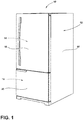
FIG. 1 is a side perspective view of a refrigerator appliance including an upper door and a lower door, according to various examples; -
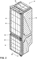
FIG. 2 is a side perspective view of a refrigerator appliance with a wrapper removed; -
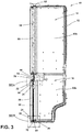
FIG. 3 is a cross-sectional view of the refrigerator appliance ofFIG. 2 taken at line III-III; -
FIG. 4 is a rear perspective view of the lower door ofFIG. 2 ; -
FIG. 5 is a cross-sectional segmented view of the lower door ofFIG. 4 taken at line V-V; -
FIG. 6 is the cross-sectional segmented view ofFIG. 4 with a gasket separated from the lower door; and -
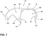
FIG. 7 is a cross-sectional view of the gasket ofFIG. 5 ; -
FIG. 8A is an enlarged view of area VIIIA ofFIG. 3 and illustrates an upper portion of a gasket assembly of the lower door; and -
FIG. 8B is an enlarged view of area VIIIB ofFIG. 3 and illustrates a lower portion of the gasket assembly of the lower door. - The components in the figures are not necessarily to scale, emphasis instead being placed upon illustrating the principles described herein.
- The present illustrated embodiments reside primarily in combinations of method steps and apparatus components related to a gasket assembly for an appliance door. Accordingly, the apparatus components and method steps have been represented, where appropriate, by conventional symbols in the drawings, showing only those specific details that are pertinent to understanding the embodiments of the present disclosure so as not to obscure the disclosure with details that will be readily apparent to those of ordinary skill in the art having the benefit of the description herein. Further, like numerals in the description and drawings represent like elements.
- For purposes of description herein, the terms "upper," "lower," "right," "left," "rear," "front," "vertical," "horizontal," and derivatives thereof shall relate to the disclosure as oriented in
FIG. 1 . Unless stated otherwise, the term "front" shall refer to the surface of the element closer to an intended viewer, and the term "rear" shall refer to the surface of the element further from the intended viewer. However, it is to be understood that the disclosure may assume various alternative orientations, except where expressly specified to the contrary. It is also to be understood that the specific devices and processes illustrated in the attached drawings, and described in the following specification are simply exemplary embodiments of the inventive concepts defined in the appended claims. Hence, specific dimensions and other physical characteristics relating to the embodiments disclosed herein are not to be considered as limiting, unless the claims expressly state otherwise. - The terms "including," "comprises," "comprising," or any other variation thereof, are intended to cover a non-exclusive inclusion, such that a process, method, article, or apparatus that comprises a list of elements does not include only those elements but may include other elements not expressly listed or inherent to such process, method, article, or apparatus. An element proceeded by "comprises a ..." does not, without more constraints, preclude the existence of additional identical elements in the process, method, article, or apparatus that comprises the element.
- Referring to
FIGS. 1-8B ,reference numeral 10 generally designates a refrigerator appliance. Therefrigerator appliance 10 includes acabinet 12 that defines acompartment door cabinet 12 and is configured to selectively seal thecompartment door door trim breaker 22. Anengagement member 24 extends from thedoor trim breaker 22. Afirst retention ridge 26 extends from afirst side 28 of theengagement member 24, and asecond retention ridge 30 extends from asecond side 32 of theengagement member 24. Thefirst retention ridge 26 is offset from thesecond retention ridge 30. Aninterior gasket 34 is positioned interior of an outer edge of thedoor 20 and is configured to fit over theengagement member 24. Thegasket 34 includes acoupling portion 36 that defines afirst retention space 38 and asecond retention space 40. Thefirst retention space 38 is configured to receive thefirst retention ridge 26, and thesecond retention space 40 is configured to receive thesecond retention ridge 30. Acontact portion 42 is integrally formed with thecoupling portion 36 and is configured to at least partially abut thecabinet 12 when thedoor 20 is closed. - Referring now to
FIGS. 1-3 , therefrigerator appliance 10 is illustrated including acabinet 12 formed by anexterior wrapper 50 and one ormore liners cabinet 12 defines arefrigerator compartment 14 configured to refrigerate consumables and afreezer compartment 16 configured to freeze consumables during normal use. Accordingly, therefrigerator compartment 14 may be kept at a temperature above the freezing point of water and generally below a temperature of from about 35° F to about 50° F, more typically below about 38° F and thefreezer compartment 16 may be kept at a temperature below the freezing point of water. Amullion 58 may separate therefrigerator compartment 14 and thefreezer compartment 16.FIGS. 1 and2 generally show a refrigerator of the bottom mount type with a swinging lower door, but it is understood that this disclosure could apply to any type of refrigerator, such as a side-by-side, French-door bottom mount, or top-mount refrigerator. - The
refrigerator compartment 14 is selectively accessible via a refrigerator compartment opening 60 defined by a refrigerator compartmenttrim breaker 62, and thefreezer compartment 16 is selectively accessible via a freezer compartment opening 66 defined by a freezer compartmenttrim breaker 68. Therefrigerator compartment 14 is selectively sealed by arefrigerator compartment door 18, and thefreezer compartment 16 is selectively sealed by afreezer compartment door 20. When thefreezer compartment door 20 is closed, thefreezer compartment door 20 is at least partially received by thefreezer compartment opening 66. As illustrated inFIG. 3 , thefreezer compartment door 20 includes anexterior gasket 70 positioned along an exterior edge of thefreezer compartment door 20 and aninterior gasket 34 positioned interior of theexterior gasket 70. The interior andexterior gaskets freezer compartment 16 when thefreezer compartment door 20 is closed. However, it is contemplated that therefrigerator compartment door 18 may have the same or similar components without departing from the scope of the present disclosure. - Referring now to
FIGS. 4-6 , thefreezer compartment door 20 includes the doortrim breaker 22 extending along an outer periphery of thefreezer compartment door 20. As best shown inFIGS. 5 and6 , the doortrim breaker 22 extends from abody 72 of adoor liner 74 and is operably coupled with thedoor liner 74. As illustrated, the doortrim breaker 22 may define aslot 76 extending along the length of the doortrim breaker 22 and configured to receive an innerperipheral edge 78 of theinner door liner 74. It will be understood that the doortrim breaker 22 may have any number of connection points for coupling the doortrim breaker 22 with various panels or liners of thefreezer compartment door 20 without departing from the scope of the present disclosure. - Referring still to
FIGS. 5 and6 , the doortrim breaker 22 defines agasket channel 80 extending about a periphery of thefreezer compartment door 20. Thegasket channel 80 may be defined exterior of theinner door liner 74 and is configured to receive ananchor 82 of theexterior gasket 70. A plurality oftabs 86 may be positioned within thegasket channel 80 and to retain theanchor 82 within thegasket channel 80. For example, each of the plurality oftabs 86 may extend from the doortrim breaker 22 into thegasket channel 80. When theanchor 82 of theexterior gasket 70 is received by thegasket channel 80, a portion of theanchor 82 is prevented from inadvertent removal from thegasket channel 80 by the plurality oftabs 86. The engagement of theanchor 82 with the plurality oftabs 86 is configured to couple theexterior gasket 70 with the doortrim breaker 22. - The
exterior gasket 70 further includes acompressible portion 84 integrally formed with theanchor 82 and extending from the doortrim breaker 22 when theanchor 82 is received by thegasket channel 80. Thecompressible portion 84 defines one ormore spaces 92. When thefreezer compartment door 20 is closed, thecompressible portion 84 is compressed, as discussed in more detail elsewhere herein. - Referring still to
FIGS. 5 and6 , the doortrim breaker 22 further includes a raisedportion 88 configured to be received by the compartment opening 66 (FIGS. 8A and8B ). Theengagement member 24 extends from the raisedportion 88 away from thedoor liner 74 and parallel to theexterior gasket 70. Theengagement member 24 may extend about the entire of the periphery of thedoor 20 or a portion of the periphery of thedoor 20. Theengagement member 24 may be a single member along its length, as illustrated, or may be a plurality ofengagement members 24 interspaced along the periphery of the doortrim breaker 22 without departing from the scope of the present disclosure. - The
engagement member 24 includes first and second opposingsides top wall 90. Thefirst side 28 is positioned proximate to theexterior gasket 70 such that theinterior gasket 34 is positioned interior of theexterior gasket 70. Theengagement member 24 is positioned to be at least partially received by thefreezer compartment opening 66 when thefreezer compartment door 20 is closed. In various examples, theengagement member 24 may be beveled where thetop wall 90 meets the first andsecond sides engagement member 24. - As illustrated in
FIG. 5 , theengagement member 24 may define theslot 76 opposite thetop wall 90 of theengagement member 24. Theslot 76 is configured to receive theedge 78 of theinner door liner 74 such that thesecond side 32 of the engagement member is parallel with theedge 78 of theinner door liner 74 and is perpendicular with thebody 72 of theinner door liner 74. - With continued reference to
FIGS. 5 and6 , thefirst side 28 of theengagement member 24 includes thefirst retention ridge 26, and thesecond side 32 of theengagement member 24 includes thesecond retention ridge 30. Thefirst retention ridge 26 extends from thefirst side 28 of theengagement member 24 toward theexterior gasket 70, and thesecond retention ridge 30 extends from thesecond side 32 of theengagement member 24 toward the center of thefreezer compartment door 20. Each of the first andsecond retention ridges interior gasket 34, as described in more detail elsewhere herein. - The
first retention ridge 26 is positioned a first distance D1 from thetop wall 90 of theengagement member 24, and thesecond retention ridge 30 is positioned a second distance D2 from thetop wall 90 of theengagement member 24. As illustrated, the first distance D1 is greater than the second distance D2 such that thefirst retention ridge 26 is positioned further from thetop wall 90 than thesecond retention ridge 30. This offsets the first andsecond retention ridges interior gasket 34. - Referring still to
FIGS. 5 and6 , thesecondary gasket 34 is configured to be positioned over theengagement member 24 of the doortrim breaker 22 to couple theinterior gasket 34 with the doortrim breaker 22 and, subsequently, to couple theinterior gasket 34 with thefreezer compartment door 20. As illustrated in detail inFIG. 7 , theinterior gasket 34 includes thecoupling portion 36 configured to couple with the engagement member 24 (FIGS. 5 and6 ) and thecontact portion 42 extending from thecoupling portion 36. As illustrated inFIGS. 8A and8B , and discussed in more detail elsewhere herein, thecontact portion 42 is configured to at least partially abut the freezer compartmenttrim breaker 68 to provide a secondary seal when thefreezer compartment door 20 is closed. - Referring now to
FIGS. 5-7 , thecoupling portion 36 of theinterior gasket 34 is shaped to complement and receive theengagement member 24. As best shown inFIG. 7 , thecoupling portion 36 defines a receivingchannel 100 configured to receive theengagement member 24 such that, when theengagement member 24 is positioned within the receivingchannel 100, aninner surface 102 of thecoupling portion 36 is in substantially continuous contact with theengagement member 24. Thecoupling portion 36 of theinterior gasket 34 may be formed of a rigid material such as, for example, a rigid PVC. The rigid material may prevent inadvertent uncoupling of theinterior gasket 34 from theengagement member 24. - The
coupling portion 36 of theinterior gasket 34 is configured to snap-engage with theengagement member 24, as illustrated inFIG. 5 . As illustrated in detail inFIG. 7 , thecoupling portion 36 includes afirst leg 104 and asecond leg 106 configured to fit over each of the first andsecond retention ridges 26, 30 (FIG. 5 ). Thefirst leg 104 defines afirst retention space 38, and thesecond leg 106 of thecoupling portion 36 defines asecond retention space 40. Each of the first andsecond retention spaces channel 100. Thefirst retention space 38 is configured to snap-engage with and receive thefirst retention ridge 26 of theengagement member 24, and thesecond retention space 40 is configured to snap-engage with and receive thesecond retention ridge 30 of the engagement member 24 (FIG. 5 ). - Referring again to
FIGS. 5-7 , the positioning of the first andsecond retention spaces second legs coupling portion 36 is configured to accommodate and match the offset of the first andsecond retention ridges first retention space 38 is defined to be spaced a third distance D3 from atop wall 110 of thecoupling portion 36. The third distance D3 is configured to complement the first distance D1 between thetop wall 90 of theengagement member 24 and thefirst retention ridge 26. Thesecond retention space 40 is defined to be spaced a fourth distance D4 from thetop wall 110 of thecoupling portion 36, and the fourth distance D4 is configured to complement the second distance D2 between thetop wall 90 of theengagement member 24 and thesecond retention ridge 30. - As shown in
FIGS. 6 and7 , to facilitate snap-engaging thecoupling portion 36 over theengagement member 24, afirst foot 114 extends from thefirst leg 104 and is angled outward from thefirst leg 104. The angle of thefirst foot 114 allows thefirst leg 104 to snap over thefirst retention ridge 26 when theinterior gasket 34 is coupled with theengagement member 24. Asecond foot 118 extends from thesecond leg 106 and is angled outward from thesecond leg 106 in a direction opposite thefirst foot 114. The angle of thesecond foot 118 allows thesecond leg 106 to snap over thesecond retention ridge 30 when theinterior gasket 34 is coupled with theengagement member 24. - As best shown in
FIG. 7 , thecontact portion 42 of theinterior gasket 34 is integrally formed with thecoupling portion 36 and is formed of a compressible and/or flexible material such as, for example, a flexible polyvinyl chloride (PVC). In various examples, thecontact portion 42 may extend over thecoupling portion 36 and extend from thefirst leg 104 of thecoupling portion 36 to thesecond leg 106 of thecoupling portion 36. Thecoupling portion 36 defines acompressible space 120 extending from thefirst side 28 of theengagement member 24 when theinterior gasket 34 is coupled with theengagement member 24. - The
contact portion 42 of theinterior gasket 34 includes abase section 124 proximate thecoupling portion 36 and anextension section 126 integrally formed with and extending from thebase section 124. Theextension section 126 may extend from thebase section 124 at an angle and/or may be generally arcuate. Theextension section 126 defines anextension space 130 in communication with thecompressible space 120 of thecontact portion 42. Theextension section 126 is shaped and positioned to at least partially abut the freezer compartmenttrim breaker 68 when thefreezer compartment door 20 is closed, as illustrated inFIGS. 8A and8B . - As illustrated in
FIGS. 8A and8B , when thefreezer compartment door 20 is closed, all or a portion of thecompressible portion 84 of theexterior gasket 70 contacts the freezer compartmenttrim breaker 68. This contact forms a primary seal for thefreezer compartment door 20. In various examples, thecompressible portion 84 may include amagnet assembly 140 configured to retain thefreezer compartment door 20 when thefreezer compartment door 20 is closed. Theexterior gasket 70 may be configured to extend about the entire exterior periphery of thedoor 20 or may extend only partially about the periphery of thedoor 20 without departing from the scope of the present disclosure. - When the
freezer compartment door 20 is closed, the raisedportion 88 of the doortrim breaker 22 is received by thefreezer compartment opening 66. Theengagement member 24 of the doortrim breaker 22 and theinterior gasket 34 are at least partially received by the freezer compartment opening 66 proximate the freezer compartmenttrim breaker 68 such that at least theextension section 126 of thecontact portion 42 abuts the freezer compartmenttrim breaker 68. The contact between theextension section 126 and the freezer compartmenttrim breaker 68 is configured to provide a secondary seal for thefreezer compartment door 20. - Referring again to
FIGS. 1-8B , theinterior gasket 34 is coupled with theengagement member 24 of the doortrim breaker 22 to provide the secondary seal for thefreezer compartment door 20 when thefreezer compartment door 20 is closed. The secondary seal may provide additional sealing for thedoor 20 which may improve the seal between thefreezer compartment door 20 and thefreezer compartment 16. Additionally, the poka-yoke feature provided by the first andsecond retention ridges second retention spaces interior gasket 34. - It will be understood by one having ordinary skill in the art that construction of the described disclosure and other components is not limited to any specific material. Other exemplary embodiments of the disclosure disclosed herein may be formed from a wide variety of materials, unless described otherwise herein.
- For purposes of this disclosure, the term "coupled" (in all of its forms, couple, coupling, coupled, etc.) generally means the joining of two components (electrical or mechanical) directly or indirectly to one another. Such joining may be stationary in nature or movable in nature. Such joining may be achieved with the two components (electrical or mechanical) and any additional intermediate members being integrally formed as a single unitary body with one another or with the two components. Such joining may be permanent in nature or may be removable or releasable in nature unless otherwise stated.
- It is also important to note that the construction and arrangement of the elements of the disclosure as shown in the exemplary embodiments is illustrative only. Although only a few embodiments of the present innovations have been described in detail in this disclosure, those skilled in the art who review this disclosure will readily appreciate that many modifications are possible (e.g., variations in sizes, dimensions, structures, shapes and proportions of the various elements, values of parameters, mounting arrangements, use of materials, colors, orientations, etc.) without materially departing from the novel teachings and advantages of the subject matter recited. For example, elements shown as integrally formed may be constructed of multiple parts or elements shown as multiple parts may be integrally formed, the operation of the interfaces may be reversed or otherwise varied, the length or width of the structures and/or members or connector or other elements of the system may be varied, the nature or number of adjustment positions provided between the elements may be varied. It should be noted that the elements and/or assemblies of the system may be constructed from any of a wide variety of materials that provide sufficient strength or durability, in any of a wide variety of colors, textures, and combinations. Accordingly, all such modifications are intended to be included within the scope of the present innovations. Other substitutions, modifications, changes, and omissions may be made in the design, operating conditions, and arrangement of the desired and other exemplary embodiments without departing from the spirit of the present innovations.
- It will be understood that any described processes or steps within described processes may be combined with other disclosed processes or steps to form structures within the scope of the present disclosure. The exemplary structures and processes disclosed herein are for illustrative purposes and are not to be construed as limiting.
Claims (14)
- A refrigerator appliance (10) comprising:a cabinet (12) defining a compartment (14, 16);a door (18, 20) hingedly coupled with the cabinet (12) and configured to selectively seal the compartment (14, 16), wherein the door (18, 20) includes a door trim breaker (22);an engagement member (24) extending from the door trim breaker (22) and having a first retention ridge (26) extending from a first side (28) of the engagement member (24) and a second retention ridge (30) extending from a second side (32) of the engagement member (24), wherein the first retention ridge (26) is offset from the second retention ridge (30); anda gasket (34) configured to fit over the engagement member (24), wherein the gasket (34) includes:a coupling portion (36) defining a first retention space (38) and a second retention space (40), wherein the first retention space (38) is configured to receive the first retention ridge (26) and the second retention space (40) is configured to receive the second retention ridge (30); anda contact portion (42) integrally formed with the coupling portion (36) and configured to at least partially abut the cabinet (12) when the door (18, 20) is closed.
- The refrigerator appliance (10) of claim 1, further comprising:
a door liner (74) coupled with the door trim breaker (22), wherein the door liner (74) has an edge (78) positioned perpendicular to a body (72) of the door liner (74). - The refrigerator appliance (10) of claim 2, wherein the door trim breaker (22) defines a slot (76) configured to receive the edge (78) of the door liner (74).
- The refrigerator appliance (10) of any one of claims 1-3, wherein the compartment (14, 16) is accessible by a compartment opening (60, 66), and further wherein the compartment opening (60, 66) is defined by a compartment trim breaker (62, 68).
- The refrigerator appliance (10) of claim 4, wherein the contact portion (42) abuts the compartment trim breaker (62, 68) when the door (18, 20) is closed.
- The refrigerator appliance (10) of either of claims 4 or 5, wherein the engagement member (24) is at least partially received by the compartment opening (60, 66) when the door (18, 20) is closed.
- The refrigerator appliance (10) of any one of claims 1-6, wherein the contact portion (42) includes an extension section (126) integrally formed with and extending from a base section (124), and further wherein the base section (124) is integrally formed with the coupling portion (36).
- The refrigerator appliance (10) of any one of claims 1-7, wherein an exterior gasket (70) includes a magnet assembly (170) configured to bias the door (18, 20) closed.
- The refrigerator appliance (10) of claim 8, wherein the door trim breaker (22) defines a gasket channel (80) configured to receive an anchor (82) of the exterior gasket (70) to couple the exterior gasket (70) with the door (18, 20).
- The refrigerator appliance (10) of any one of claims 1-9, wherein the coupling portion (36) is formed of a first material and the contact portion (42) is formed of a second material, and wherein the second material is more flexible than the first material.
- The refrigerator appliance (10) of any one of claims 1-10, wherein the engagement member (24) is beveled where a top wall (90) of the engagement member (24) meets the first and second sides (28, 32) of the engagement member (24).
- The refrigerator appliance (10) of claim 9, further comprising:
a plurality of tabs (86) positioned within the gasket channel (80) to retain the anchor (82) within the gasket channel (80). - The refrigerator appliance (10) of any one of claims 1-12, wherein the coupling portion (36) includes a first leg (104) defining the first retention space (38) and a second leg (106) defining the second retention space (40).
- The refrigerator appliance (10) of claim 13, wherein the first leg (104) includes a first foot (114) extending outward from the first leg (104) and the second leg (106) includes a second foot (118) extending outward from the second leg (106).
Applications Claiming Priority (1)
| Application Number | Priority Date | Filing Date | Title |
|---|---|---|---|
| US16/870,399 US11898791B2 (en) | 2020-05-08 | 2020-05-08 | Appliance door gasket assembly |
Publications (2)
| Publication Number | Publication Date |
|---|---|
| EP3907450A1 true EP3907450A1 (en) | 2021-11-10 |
| EP3907450B1 EP3907450B1 (en) | 2023-06-21 |
Family
ID=75529796
Family Applications (1)
| Application Number | Title | Priority Date | Filing Date |
|---|---|---|---|
| EP21168229.9A Active EP3907450B1 (en) | 2020-05-08 | 2021-04-13 | Refrigerator appliance with door gasket assembly |
Country Status (3)
| Country | Link |
|---|---|
| US (1) | US11898791B2 (en) |
| EP (1) | EP3907450B1 (en) |
| CN (1) | CN113623929A (en) |
Families Citing this family (6)
| Publication number | Priority date | Publication date | Assignee | Title |
|---|---|---|---|---|
| US11486629B2 (en) | 2020-06-25 | 2022-11-01 | Whirlpool Corporation | Refrigeration appliance cabinet assembly |
| USD1075858S1 (en) * | 2021-08-26 | 2025-05-20 | Jinlong Lin | Refrigerator door |
| US12398947B2 (en) * | 2023-07-21 | 2025-08-26 | Whirlpool Corporation | Refrigeration appliance with a door projection to reduce thermal transfer at door and cabinet interface |
| US20250044016A1 (en) * | 2023-08-03 | 2025-02-06 | Whirlpool Corporation | Support system for a vacuum insulated panel |
| US12504217B2 (en) | 2023-08-04 | 2025-12-23 | Whirlpool Corporation | Insulated structure for a refrigeration unit |
| US20250341359A1 (en) * | 2024-05-03 | 2025-11-06 | Whirlpool Corporation | Trim breaker profile for a vacuum insulated structure |
Citations (3)
| Publication number | Priority date | Publication date | Assignee | Title |
|---|---|---|---|---|
| US5289657A (en) * | 1992-03-13 | 1994-03-01 | The Standard Products Company | Refrigerator gasket and retainer |
| EP3623731A1 (en) * | 2018-09-13 | 2020-03-18 | Whirlpool Corporation | Ferromagnetic cover for a trim breaker of an appliance cabinet |
| EP3647696A1 (en) * | 2018-10-31 | 2020-05-06 | Whirlpool Corporation | Polymer trim breaker having gas-blocking flakes and an epoxy coating |
Family Cites Families (17)
| Publication number | Priority date | Publication date | Assignee | Title |
|---|---|---|---|---|
| US4509292A (en) | 1983-03-03 | 1985-04-09 | Arthur Smith Industries, Inc. | Door gasket |
| DE3525539C1 (en) | 1985-07-17 | 1986-11-27 | Bosch-Siemens Hausgeräte GmbH, 8000 München | Door seal, especially door seal for refrigerators and freezers or the like. |
| US4916864A (en) | 1989-05-05 | 1990-04-17 | White Consolidated Industries, Inc. | Snap-in gasket system for refrigerator and freezer doors |
| DE4304500A1 (en) * | 1993-02-15 | 1994-08-18 | Bosch Siemens Hausgeraete | Sealing arrangement, in particular for the door of a refrigerating unit or freezing unit |
| JP2000154968A (en) * | 1998-11-19 | 2000-06-06 | Sharp Corp | refrigerator |
| JP3871500B2 (en) * | 2000-07-07 | 2007-01-24 | 株式会社東芝 | Refrigerator door |
| SE519195C2 (en) | 2001-06-14 | 2003-01-28 | Electrolux Ab | Door seal at a refrigerator or freezer |
| ITMI20050121A1 (en) | 2005-01-28 | 2006-07-29 | Ilpea Ind Spa | GASKET FOR REFRIGERATED FURNITURE WITH HIGH PROPERTIES OF THERMAL INSULATION |
| ITMI20050455A1 (en) | 2005-03-21 | 2006-09-22 | Ilpea Ind Spa | GASKET FOR REFRIGERATED FURNITURE DOORS WITH HIGH PROPERTIES OF THERMAL INSULATION |
| IT1402926B1 (en) | 2010-12-10 | 2013-09-27 | Ilpea Ind Spa | MAGNETIC GASKET FOR REFRIGERATED FURNITURE |
| JP6207453B2 (en) * | 2014-04-17 | 2017-10-04 | 三菱電機株式会社 | refrigerator |
| US11320193B2 (en) * | 2016-07-26 | 2022-05-03 | Whirlpool Corporation | Vacuum insulated structure trim breaker |
| US9879900B1 (en) * | 2016-09-06 | 2018-01-30 | Whirlpool Corporation | Column cabinet construction and method for door construction |
| US10234194B2 (en) * | 2017-03-16 | 2019-03-19 | Sub-Zero, Inc. | Door manufacturing method for a freezer drawer |
| US10408528B2 (en) * | 2017-03-16 | 2019-09-10 | Sub-Zero, Inc. | Single door covering a freezer compartment and a refrigerator compartment |
| US11313611B2 (en) * | 2019-05-01 | 2022-04-26 | Whirlpool Corporation | Construction method for vacuum insulated door |
| US11340008B1 (en) * | 2021-01-20 | 2022-05-24 | Whirlpool Corporation | Appliance trim breaker assembly |
-
2020
- 2020-05-08 US US16/870,399 patent/US11898791B2/en active Active
-
2021
- 2021-04-13 EP EP21168229.9A patent/EP3907450B1/en active Active
- 2021-05-08 CN CN202110500448.XA patent/CN113623929A/en active Pending
Patent Citations (3)
| Publication number | Priority date | Publication date | Assignee | Title |
|---|---|---|---|---|
| US5289657A (en) * | 1992-03-13 | 1994-03-01 | The Standard Products Company | Refrigerator gasket and retainer |
| EP3623731A1 (en) * | 2018-09-13 | 2020-03-18 | Whirlpool Corporation | Ferromagnetic cover for a trim breaker of an appliance cabinet |
| EP3647696A1 (en) * | 2018-10-31 | 2020-05-06 | Whirlpool Corporation | Polymer trim breaker having gas-blocking flakes and an epoxy coating |
Also Published As
| Publication number | Publication date |
|---|---|
| CN113623929A (en) | 2021-11-09 |
| EP3907450B1 (en) | 2023-06-21 |
| US11898791B2 (en) | 2024-02-13 |
| US20210348831A1 (en) | 2021-11-11 |
Similar Documents
| Publication | Publication Date | Title |
|---|---|---|
| US11898791B2 (en) | Appliance door gasket assembly | |
| US11340008B1 (en) | Appliance trim breaker assembly | |
| US12007156B2 (en) | Door vent sealing assembly | |
| US3380615A (en) | Refrigeration apparatus cabinet construction | |
| EP3647697B1 (en) | Cabinet assembly of an appliance | |
| US20220252333A1 (en) | Trim breaker for an insulated appliance | |
| EP3851779A1 (en) | Illuminated trim assembly for an appliance | |
| US2786241A (en) | Refrigerator door and gasket seal | |
| US8490333B2 (en) | Sealing gaskets | |
| EP4227617A1 (en) | Refrigeration unit | |
| US11768029B2 (en) | Door gasket assembly for a refrigerated appliance | |
| RU2210704C2 (en) | Plastic section with corrugated lining | |
| US12313332B2 (en) | Appliance trim breaker | |
| US3174642A (en) | Refrigerator cabinet construction | |
| JP3857802B2 (en) | Cooling storage | |
| JP2000097550A (en) | Refrigerator | |
| EP0942245A3 (en) | Door for domestic refrigerators | |
| CN217154646U (en) | Refrigeration device | |
| EP1240468B1 (en) | A gasket arrangement for the cabinet door of a refrigeration appliance | |
| JP2005090845A (en) | refrigerator | |
| EP4317872A1 (en) | Attachment assembly for an insulated door | |
| KR20030085305A (en) | Refrigerator door | |
| KR100217405B1 (en) | Middle hinge of door for refrigerator | |
| JPH05164457A (en) | Connecting device for cabinets such as refrigerators | |
| EP2843334A1 (en) | Gasket for heat insulated cabinets |
Legal Events
| Date | Code | Title | Description |
|---|---|---|---|
| PUAI | Public reference made under article 153(3) epc to a published international application that has entered the european phase |
Free format text: ORIGINAL CODE: 0009012 |
|
| STAA | Information on the status of an ep patent application or granted ep patent |
Free format text: STATUS: THE APPLICATION HAS BEEN PUBLISHED |
|
| AK | Designated contracting states |
Kind code of ref document: A1 Designated state(s): AL AT BE BG CH CY CZ DE DK EE ES FI FR GB GR HR HU IE IS IT LI LT LU LV MC MK MT NL NO PL PT RO RS SE SI SK SM TR |
|
| B565 | Issuance of search results under rule 164(2) epc |
Effective date: 20211012 |
|
| STAA | Information on the status of an ep patent application or granted ep patent |
Free format text: STATUS: REQUEST FOR EXAMINATION WAS MADE |
|
| 17P | Request for examination filed |
Effective date: 20220504 |
|
| RBV | Designated contracting states (corrected) |
Designated state(s): AL AT BE BG CH CY CZ DE DK EE ES FI FR GB GR HR HU IE IS IT LI LT LU LV MC MK MT NL NO PL PT RO RS SE SI SK SM TR |
|
| RIC1 | Information provided on ipc code assigned before grant |
Ipc: F25D 23/08 20060101ALI20230127BHEP Ipc: F25D 23/02 20060101AFI20230127BHEP |
|
| GRAP | Despatch of communication of intention to grant a patent |
Free format text: ORIGINAL CODE: EPIDOSNIGR1 |
|
| STAA | Information on the status of an ep patent application or granted ep patent |
Free format text: STATUS: GRANT OF PATENT IS INTENDED |
|
| INTG | Intention to grant announced |
Effective date: 20230328 |
|
| GRAS | Grant fee paid |
Free format text: ORIGINAL CODE: EPIDOSNIGR3 |
|
| GRAA | (expected) grant |
Free format text: ORIGINAL CODE: 0009210 |
|
| STAA | Information on the status of an ep patent application or granted ep patent |
Free format text: STATUS: THE PATENT HAS BEEN GRANTED |
|
| AK | Designated contracting states |
Kind code of ref document: B1 Designated state(s): AL AT BE BG CH CY CZ DE DK EE ES FI FR GB GR HR HU IE IS IT LI LT LU LV MC MK MT NL NO PL PT RO RS SE SI SK SM TR |
|
| REG | Reference to a national code |
Ref country code: CH Ref legal event code: EP |
|
| REG | Reference to a national code |
Ref country code: DE Ref legal event code: R096 Ref document number: 602021002992 Country of ref document: DE |
|
| REG | Reference to a national code |
Ref country code: AT Ref legal event code: REF Ref document number: 1581154 Country of ref document: AT Kind code of ref document: T Effective date: 20230715 |
|
| REG | Reference to a national code |
Ref country code: IE Ref legal event code: FG4D |
|
| REG | Reference to a national code |
Ref country code: LT Ref legal event code: MG9D |
|
| REG | Reference to a national code |
Ref country code: NL Ref legal event code: MP Effective date: 20230621 |
|
| PG25 | Lapsed in a contracting state [announced via postgrant information from national office to epo] |
Ref country code: SE Free format text: LAPSE BECAUSE OF FAILURE TO SUBMIT A TRANSLATION OF THE DESCRIPTION OR TO PAY THE FEE WITHIN THE PRESCRIBED TIME-LIMIT Effective date: 20230621 Ref country code: NO Free format text: LAPSE BECAUSE OF FAILURE TO SUBMIT A TRANSLATION OF THE DESCRIPTION OR TO PAY THE FEE WITHIN THE PRESCRIBED TIME-LIMIT Effective date: 20230921 |
|
| REG | Reference to a national code |
Ref country code: AT Ref legal event code: MK05 Ref document number: 1581154 Country of ref document: AT Kind code of ref document: T Effective date: 20230621 |
|
| PG25 | Lapsed in a contracting state [announced via postgrant information from national office to epo] |
Ref country code: RS Free format text: LAPSE BECAUSE OF FAILURE TO SUBMIT A TRANSLATION OF THE DESCRIPTION OR TO PAY THE FEE WITHIN THE PRESCRIBED TIME-LIMIT Effective date: 20230621 Ref country code: NL Free format text: LAPSE BECAUSE OF FAILURE TO SUBMIT A TRANSLATION OF THE DESCRIPTION OR TO PAY THE FEE WITHIN THE PRESCRIBED TIME-LIMIT Effective date: 20230621 Ref country code: LV Free format text: LAPSE BECAUSE OF FAILURE TO SUBMIT A TRANSLATION OF THE DESCRIPTION OR TO PAY THE FEE WITHIN THE PRESCRIBED TIME-LIMIT Effective date: 20230621 Ref country code: LT Free format text: LAPSE BECAUSE OF FAILURE TO SUBMIT A TRANSLATION OF THE DESCRIPTION OR TO PAY THE FEE WITHIN THE PRESCRIBED TIME-LIMIT Effective date: 20230621 Ref country code: HR Free format text: LAPSE BECAUSE OF FAILURE TO SUBMIT A TRANSLATION OF THE DESCRIPTION OR TO PAY THE FEE WITHIN THE PRESCRIBED TIME-LIMIT Effective date: 20230621 Ref country code: GR Free format text: LAPSE BECAUSE OF FAILURE TO SUBMIT A TRANSLATION OF THE DESCRIPTION OR TO PAY THE FEE WITHIN THE PRESCRIBED TIME-LIMIT Effective date: 20230922 |
|
| PG25 | Lapsed in a contracting state [announced via postgrant information from national office to epo] |
Ref country code: FI Free format text: LAPSE BECAUSE OF FAILURE TO SUBMIT A TRANSLATION OF THE DESCRIPTION OR TO PAY THE FEE WITHIN THE PRESCRIBED TIME-LIMIT Effective date: 20230621 |
|
| PG25 | Lapsed in a contracting state [announced via postgrant information from national office to epo] |
Ref country code: SK Free format text: LAPSE BECAUSE OF FAILURE TO SUBMIT A TRANSLATION OF THE DESCRIPTION OR TO PAY THE FEE WITHIN THE PRESCRIBED TIME-LIMIT Effective date: 20230621 |
|
| PG25 | Lapsed in a contracting state [announced via postgrant information from national office to epo] |
Ref country code: ES Free format text: LAPSE BECAUSE OF FAILURE TO SUBMIT A TRANSLATION OF THE DESCRIPTION OR TO PAY THE FEE WITHIN THE PRESCRIBED TIME-LIMIT Effective date: 20230621 |
|
| PG25 | Lapsed in a contracting state [announced via postgrant information from national office to epo] |
Ref country code: IS Free format text: LAPSE BECAUSE OF FAILURE TO SUBMIT A TRANSLATION OF THE DESCRIPTION OR TO PAY THE FEE WITHIN THE PRESCRIBED TIME-LIMIT Effective date: 20231021 |
|
| PG25 | Lapsed in a contracting state [announced via postgrant information from national office to epo] |
Ref country code: SM Free format text: LAPSE BECAUSE OF FAILURE TO SUBMIT A TRANSLATION OF THE DESCRIPTION OR TO PAY THE FEE WITHIN THE PRESCRIBED TIME-LIMIT Effective date: 20230621 Ref country code: SK Free format text: LAPSE BECAUSE OF FAILURE TO SUBMIT A TRANSLATION OF THE DESCRIPTION OR TO PAY THE FEE WITHIN THE PRESCRIBED TIME-LIMIT Effective date: 20230621 Ref country code: RO Free format text: LAPSE BECAUSE OF FAILURE TO SUBMIT A TRANSLATION OF THE DESCRIPTION OR TO PAY THE FEE WITHIN THE PRESCRIBED TIME-LIMIT Effective date: 20230621 Ref country code: PT Free format text: LAPSE BECAUSE OF FAILURE TO SUBMIT A TRANSLATION OF THE DESCRIPTION OR TO PAY THE FEE WITHIN THE PRESCRIBED TIME-LIMIT Effective date: 20231023 Ref country code: IS Free format text: LAPSE BECAUSE OF FAILURE TO SUBMIT A TRANSLATION OF THE DESCRIPTION OR TO PAY THE FEE WITHIN THE PRESCRIBED TIME-LIMIT Effective date: 20231021 Ref country code: ES Free format text: LAPSE BECAUSE OF FAILURE TO SUBMIT A TRANSLATION OF THE DESCRIPTION OR TO PAY THE FEE WITHIN THE PRESCRIBED TIME-LIMIT Effective date: 20230621 Ref country code: EE Free format text: LAPSE BECAUSE OF FAILURE TO SUBMIT A TRANSLATION OF THE DESCRIPTION OR TO PAY THE FEE WITHIN THE PRESCRIBED TIME-LIMIT Effective date: 20230621 Ref country code: CZ Free format text: LAPSE BECAUSE OF FAILURE TO SUBMIT A TRANSLATION OF THE DESCRIPTION OR TO PAY THE FEE WITHIN THE PRESCRIBED TIME-LIMIT Effective date: 20230621 Ref country code: AT Free format text: LAPSE BECAUSE OF FAILURE TO SUBMIT A TRANSLATION OF THE DESCRIPTION OR TO PAY THE FEE WITHIN THE PRESCRIBED TIME-LIMIT Effective date: 20230621 |
|
| PG25 | Lapsed in a contracting state [announced via postgrant information from national office to epo] |
Ref country code: PL Free format text: LAPSE BECAUSE OF FAILURE TO SUBMIT A TRANSLATION OF THE DESCRIPTION OR TO PAY THE FEE WITHIN THE PRESCRIBED TIME-LIMIT Effective date: 20230621 |
|
| REG | Reference to a national code |
Ref country code: DE Ref legal event code: R097 Ref document number: 602021002992 Country of ref document: DE |
|
| PLBE | No opposition filed within time limit |
Free format text: ORIGINAL CODE: 0009261 |
|
| STAA | Information on the status of an ep patent application or granted ep patent |
Free format text: STATUS: NO OPPOSITION FILED WITHIN TIME LIMIT |
|
| PG25 | Lapsed in a contracting state [announced via postgrant information from national office to epo] |
Ref country code: DK Free format text: LAPSE BECAUSE OF FAILURE TO SUBMIT A TRANSLATION OF THE DESCRIPTION OR TO PAY THE FEE WITHIN THE PRESCRIBED TIME-LIMIT Effective date: 20230621 |
|
| PG25 | Lapsed in a contracting state [announced via postgrant information from national office to epo] |
Ref country code: SI Free format text: LAPSE BECAUSE OF FAILURE TO SUBMIT A TRANSLATION OF THE DESCRIPTION OR TO PAY THE FEE WITHIN THE PRESCRIBED TIME-LIMIT Effective date: 20230621 |
|
| 26N | No opposition filed |
Effective date: 20240322 |
|
| PG25 | Lapsed in a contracting state [announced via postgrant information from national office to epo] |
Ref country code: SI Free format text: LAPSE BECAUSE OF FAILURE TO SUBMIT A TRANSLATION OF THE DESCRIPTION OR TO PAY THE FEE WITHIN THE PRESCRIBED TIME-LIMIT Effective date: 20230621 |
|
| PGFP | Annual fee paid to national office [announced via postgrant information from national office to epo] |
Ref country code: DE Payment date: 20240429 Year of fee payment: 4 |
|
| PGFP | Annual fee paid to national office [announced via postgrant information from national office to epo] |
Ref country code: IT Payment date: 20240430 Year of fee payment: 4 Ref country code: FR Payment date: 20240430 Year of fee payment: 4 |
|
| PG25 | Lapsed in a contracting state [announced via postgrant information from national office to epo] |
Ref country code: BG Free format text: LAPSE BECAUSE OF FAILURE TO SUBMIT A TRANSLATION OF THE DESCRIPTION OR TO PAY THE FEE WITHIN THE PRESCRIBED TIME-LIMIT Effective date: 20230621 |
|
| PG25 | Lapsed in a contracting state [announced via postgrant information from national office to epo] |
Ref country code: MC Free format text: LAPSE BECAUSE OF FAILURE TO SUBMIT A TRANSLATION OF THE DESCRIPTION OR TO PAY THE FEE WITHIN THE PRESCRIBED TIME-LIMIT Effective date: 20230621 |
|
| PG25 | Lapsed in a contracting state [announced via postgrant information from national office to epo] |
Ref country code: MC Free format text: LAPSE BECAUSE OF FAILURE TO SUBMIT A TRANSLATION OF THE DESCRIPTION OR TO PAY THE FEE WITHIN THE PRESCRIBED TIME-LIMIT Effective date: 20230621 Ref country code: BG Free format text: LAPSE BECAUSE OF FAILURE TO SUBMIT A TRANSLATION OF THE DESCRIPTION OR TO PAY THE FEE WITHIN THE PRESCRIBED TIME-LIMIT Effective date: 20230621 |
|
| REG | Reference to a national code |
Ref country code: CH Ref legal event code: PL |
|
| PG25 | Lapsed in a contracting state [announced via postgrant information from national office to epo] |
Ref country code: LU Free format text: LAPSE BECAUSE OF NON-PAYMENT OF DUE FEES Effective date: 20240413 |
|
| REG | Reference to a national code |
Ref country code: BE Ref legal event code: MM Effective date: 20240430 |
|
| PG25 | Lapsed in a contracting state [announced via postgrant information from national office to epo] |
Ref country code: LU Free format text: LAPSE BECAUSE OF NON-PAYMENT OF DUE FEES Effective date: 20240413 |
|
| PG25 | Lapsed in a contracting state [announced via postgrant information from national office to epo] |
Ref country code: BE Free format text: LAPSE BECAUSE OF NON-PAYMENT OF DUE FEES Effective date: 20240430 |
|
| PG25 | Lapsed in a contracting state [announced via postgrant information from national office to epo] |
Ref country code: BE Free format text: LAPSE BECAUSE OF NON-PAYMENT OF DUE FEES Effective date: 20240430 Ref country code: CH Free format text: LAPSE BECAUSE OF NON-PAYMENT OF DUE FEES Effective date: 20240430 |
|
| PG25 | Lapsed in a contracting state [announced via postgrant information from national office to epo] |
Ref country code: IE Free format text: LAPSE BECAUSE OF NON-PAYMENT OF DUE FEES Effective date: 20240413 |
|
| PG25 | Lapsed in a contracting state [announced via postgrant information from national office to epo] |
Ref country code: CY Free format text: LAPSE BECAUSE OF FAILURE TO SUBMIT A TRANSLATION OF THE DESCRIPTION OR TO PAY THE FEE WITHIN THE PRESCRIBED TIME-LIMIT; INVALID AB INITIO Effective date: 20210413 |
|
| PG25 | Lapsed in a contracting state [announced via postgrant information from national office to epo] |
Ref country code: HU Free format text: LAPSE BECAUSE OF FAILURE TO SUBMIT A TRANSLATION OF THE DESCRIPTION OR TO PAY THE FEE WITHIN THE PRESCRIBED TIME-LIMIT; INVALID AB INITIO Effective date: 20210413 |
|
| REG | Reference to a national code |
Ref country code: DE Ref legal event code: R119 Ref document number: 602021002992 Country of ref document: DE |
|
| GBPC | Gb: european patent ceased through non-payment of renewal fee |
Effective date: 20250413 |
|
| PG25 | Lapsed in a contracting state [announced via postgrant information from national office to epo] |
Ref country code: DE Free format text: LAPSE BECAUSE OF NON-PAYMENT OF DUE FEES Effective date: 20251104 |
|
| PG25 | Lapsed in a contracting state [announced via postgrant information from national office to epo] |
Ref country code: GB Free format text: LAPSE BECAUSE OF NON-PAYMENT OF DUE FEES Effective date: 20250413 |
|
| PG25 | Lapsed in a contracting state [announced via postgrant information from national office to epo] |
Ref country code: FR Free format text: LAPSE BECAUSE OF NON-PAYMENT OF DUE FEES Effective date: 20250430 |
|
| PG25 | Lapsed in a contracting state [announced via postgrant information from national office to epo] |
Ref country code: IT Free format text: LAPSE BECAUSE OF NON-PAYMENT OF DUE FEES Effective date: 20250413 |