EP3907392A1 - Gas turbine engine aft bearing arrangement - Google Patents
Gas turbine engine aft bearing arrangement Download PDFInfo
- Publication number
- EP3907392A1 EP3907392A1 EP21175715.8A EP21175715A EP3907392A1 EP 3907392 A1 EP3907392 A1 EP 3907392A1 EP 21175715 A EP21175715 A EP 21175715A EP 3907392 A1 EP3907392 A1 EP 3907392A1
- Authority
- EP
- European Patent Office
- Prior art keywords
- turbine
- hub
- spool
- gas turbine
- bearings
- Prior art date
- Legal status (The legal status is an assumption and is not a legal conclusion. Google has not performed a legal analysis and makes no representation as to the accuracy of the status listed.)
- Withdrawn
Links
- 239000000446 fuel Substances 0.000 description 4
- 230000003068 static effect Effects 0.000 description 2
- 230000004323 axial length Effects 0.000 description 1
- 230000006835 compression Effects 0.000 description 1
- 238000007906 compression Methods 0.000 description 1
- 238000012986 modification Methods 0.000 description 1
- 230000004048 modification Effects 0.000 description 1
Images


Classifications
-
- F—MECHANICAL ENGINEERING; LIGHTING; HEATING; WEAPONS; BLASTING
- F02—COMBUSTION ENGINES; HOT-GAS OR COMBUSTION-PRODUCT ENGINE PLANTS
- F02C—GAS-TURBINE PLANTS; AIR INTAKES FOR JET-PROPULSION PLANTS; CONTROLLING FUEL SUPPLY IN AIR-BREATHING JET-PROPULSION PLANTS
- F02C7/00—Features, components parts, details or accessories, not provided for in, or of interest apart form groups F02C1/00 - F02C6/00; Air intakes for jet-propulsion plants
- F02C7/06—Arrangements of bearings; Lubricating
-
- F—MECHANICAL ENGINEERING; LIGHTING; HEATING; WEAPONS; BLASTING
- F01—MACHINES OR ENGINES IN GENERAL; ENGINE PLANTS IN GENERAL; STEAM ENGINES
- F01D—NON-POSITIVE DISPLACEMENT MACHINES OR ENGINES, e.g. STEAM TURBINES
- F01D25/00—Component parts, details, or accessories, not provided for in, or of interest apart from, other groups
- F01D25/16—Arrangement of bearings; Supporting or mounting bearings in casings
- F01D25/162—Bearing supports
-
- F—MECHANICAL ENGINEERING; LIGHTING; HEATING; WEAPONS; BLASTING
- F02—COMBUSTION ENGINES; HOT-GAS OR COMBUSTION-PRODUCT ENGINE PLANTS
- F02C—GAS-TURBINE PLANTS; AIR INTAKES FOR JET-PROPULSION PLANTS; CONTROLLING FUEL SUPPLY IN AIR-BREATHING JET-PROPULSION PLANTS
- F02C3/00—Gas-turbine plants characterised by the use of combustion products as the working fluid
-
- F—MECHANICAL ENGINEERING; LIGHTING; HEATING; WEAPONS; BLASTING
- F05—INDEXING SCHEMES RELATING TO ENGINES OR PUMPS IN VARIOUS SUBCLASSES OF CLASSES F01-F04
- F05D—INDEXING SCHEME FOR ASPECTS RELATING TO NON-POSITIVE-DISPLACEMENT MACHINES OR ENGINES, GAS-TURBINES OR JET-PROPULSION PLANTS
- F05D2240/00—Components
- F05D2240/50—Bearings
- F05D2240/52—Axial thrust bearings
-
- F—MECHANICAL ENGINEERING; LIGHTING; HEATING; WEAPONS; BLASTING
- F05—INDEXING SCHEMES RELATING TO ENGINES OR PUMPS IN VARIOUS SUBCLASSES OF CLASSES F01-F04
- F05D—INDEXING SCHEME FOR ASPECTS RELATING TO NON-POSITIVE-DISPLACEMENT MACHINES OR ENGINES, GAS-TURBINES OR JET-PROPULSION PLANTS
- F05D2250/00—Geometry
- F05D2250/30—Arrangement of components
- F05D2250/38—Arrangement of components angled, e.g. sweep angle
-
- F—MECHANICAL ENGINEERING; LIGHTING; HEATING; WEAPONS; BLASTING
- F05—INDEXING SCHEMES RELATING TO ENGINES OR PUMPS IN VARIOUS SUBCLASSES OF CLASSES F01-F04
- F05D—INDEXING SCHEME FOR ASPECTS RELATING TO NON-POSITIVE-DISPLACEMENT MACHINES OR ENGINES, GAS-TURBINES OR JET-PROPULSION PLANTS
- F05D2260/00—Function
- F05D2260/96—Preventing, counteracting or reducing vibration or noise
-
- Y—GENERAL TAGGING OF NEW TECHNOLOGICAL DEVELOPMENTS; GENERAL TAGGING OF CROSS-SECTIONAL TECHNOLOGIES SPANNING OVER SEVERAL SECTIONS OF THE IPC; TECHNICAL SUBJECTS COVERED BY FORMER USPC CROSS-REFERENCE ART COLLECTIONS [XRACs] AND DIGESTS
- Y02—TECHNOLOGIES OR APPLICATIONS FOR MITIGATION OR ADAPTATION AGAINST CLIMATE CHANGE
- Y02T—CLIMATE CHANGE MITIGATION TECHNOLOGIES RELATED TO TRANSPORTATION
- Y02T50/00—Aeronautics or air transport
- Y02T50/60—Efficient propulsion technologies, e.g. for aircraft
Definitions
- This disclosure relates to a bearing arrangement for a gas turbine engine.
- a typical jet engine has two or three spools, or shafts, that transmit torque between the turbine and compressor sections of the engine.
- Each of these spools is typically supported by two bearings.
- One bearing for example, a ball bearing, is arranged at a forward end of the spool and is configured to react to both axial and radial loads.
- Another bearing for example, a roller bearing or journal bearing is arranged at the aft end of the spool and is configured to react only to radial loads. This bearing arrangement fully constrains the shaft except for rotation, and axial movement of one free end is permitted to accommodate engine axial growth.
- An example gas turbine engine includes a turbine and first and second spools coaxial with one another.
- the first spool is arranged within the second spool and extends between forward and aft ends.
- the aft end extends axially beyond the second spool and supports the turbine.
- a housing is arranged downstream from the turbine.
- First and second bearings are mounted to the aft end of the first spool and supported by the housing portion.
- a combustor is included, as well as high and low pressure turbines arranged downstream from the combustor.
- the high pressure turbine is mounted on the second spool.
- the low pressure turbine is mounted on the first spool and corresponds to the turbine.
- the housing portion corresponds to a turbine exhaust case and includes a bearing hub removably secured to an annular flange.
- the first and second bearings are mounted on the bearing hub.
- a bearing compartment is includes, and first and second bearings are arranged in the bearing compartment aft of the second spool.
- the low pressure turbine includes multiple turbine rotors.
- the first bearing is arranged axially forward of an aft side of a last rotor stage of the low pressure turbine.
- the bearing hub includes first and second hub walls respectively supporting the first and second bearings.
- the first and second hub walls are inclined radially outward to the first and second bearings from an annular apex at which the first and second hub walls are joined near the annular flange.
- a portion of the first hub wall is arranged radially beneath the low pressure turbine.
- first and second bearings are spaced apart from one another approximately 4-12 inches (10-30 cm).
- the first hub wall is oriented at a first angle of between 30° and 60°.
- the second hub wall is oriented at a second angle of between 30° and 60°.
- the annular flange is oriented relative to the first hub wall at a third angle of between 0° and 30°.
- the first angle is about 45° and the third angle is about 0°.
- the multiple turbine rotors include first, second and third turbine rotors.
- the third turbine rotor corresponds to the last rotor stage.
- the first turbine rotor corresponds to a forward-most rotor stage, and the second turbine rotor is arranged axially between the first and second rotors.
- a low pressure turbine hub is included and is mounted on the first spool and secured to the second turbine hub for supporting the multiple turbine rotors.
- a bearing hub for a gas turbine engine includes first and second hub walls integrally formed with one another to provide a unitary structure.
- the first and second hub walls are inclined radially outward from an annular apex; and first and second bearings respectively supported by the first and second walls opposite the apex.
- first and second bearings are roller bearings.
- first and second hub walls each are respectively oriented at first and second angles each of between 30° and 60° relative to an axis of the bearing hub.
- first and second angles are each about 45°.
- a gas turbine engine in another embodiment, includes a fan and a compressor section fluidly connected to the fan.
- the compressor includes a high pressure compressor and a low pressure compressor.
- a combustor is fluidly connected to the compressor section, and a turbine section is fluidly connected to the combustor.
- the turbine section includes a high pressure turbine coupled to the high pressure compressor via a shaft, and a low pressure turbine.
- First and second hub walls are integrally formed with one another to provide a unitary structure. The first and second hub walls are inclined radially outward from an annular apex at which the first and second hub walls are joined.
- a turbine exhaust case is arranged downstream from the low pressure turbine supporting the annular apex.
- First and second bearings are respectively supported by the first and second walls opposite the apex.
- the gas turbine engine is a high bypass geared aircraft engine having a bypass ratio of greater than about six (6).
- the gas turbine engine includes a low Fan Pressure Ratio of less than about 1.45.
- the low pressure turbine has a pressure ratio that is greater than about 5.
- FIG. 1 schematically illustrates a gas turbine engine 20.
- the gas turbine engine 20 is disclosed herein as a two-spool turbofan that generally incorporates a fan section 22, a compressor section 24, a combustor section 26 and a turbine section 28.
- Alternative engines might include an augmentor section (not shown) among other systems or features.
- the fan section 22 drives air along a bypass flowpath while the compressor section 24 drives air along a core flowpath for compression and communication into the combustor section 26 then expansion through the turbine section 28.
- FIG. 1 schematically illustrates a gas turbine engine 20.
- the gas turbine engine 20 is disclosed herein as a two-spool turbofan that generally incorporates a fan section 22, a compressor section 24, a combustor section 26 and a turbine section 28.
- Alternative engines might include an augmentor section (not shown) among other systems or features.
- the fan section 22 drives air along a bypass flowpath while the compressor section 24 drives air along a core flowpath for compression and communication into the combustor section 26
- the engine 20 generally includes a low speed spool 30 and a high speed spool 32 mounted for rotation about an engine central longitudinal axis A relative to an engine static structure or housing 58 via several bearing systems 38. It should be understood that various bearing systems 38 at various locations may alternatively or additionally be provided.
- the housing 58 includes first, second, third, and fourth housing portions 58A, 58B, 58C, 58D. The third and fourth housing portions 58C, 58D respectively correspond to a mid-turbine frame and a turbine exhaust case.
- the low speed spool 30 generally includes an inner shaft 40 that interconnects a fan 42, a low pressure compressor 44 and a low pressure turbine 46.
- the inner shaft 40 is connected to the fan 42 through a geared architecture 48 to drive the fan 42 at a lower speed than the low speed spool 30.
- the high speed spool 32 includes an outer shaft 50 that interconnects a high pressure compressor 52 and high pressure turbine 54.
- a combustor 56 is arranged between the high pressure compressor 52 and the high pressure turbine 54.
- the mid-turbine frame 58C of the engine static structure 58 is arranged generally between the high pressure turbine 54 and the low pressure turbine 46.
- the mid-turbine frame 58C supports one or more bearing systems 38 in the turbine section 28.
- the turbine exhaust case 58D is arranged downstream from the low pressure turbine 46 and may support one or more bearing systems as well.
- the inner shaft 40 and the outer shaft 50 are concentric and rotate via bearing systems 38 about the engine central longitudinal axis A, which is collinear with their longitudinal axes.
- the core airflow is compressed by the low pressure compressor 44 then the high pressure compressor 52, mixed and burned with fuel in the combustor 56, then expanded over the high pressure turbine 54 and low pressure turbine 46.
- the mid-turbine frame 58C includes airfoils 59 which are in the core airflow path.
- the turbines 46, 54 rotationally drive the respective low speed spool 30 and high speed spool 32 in response to the expansion.
- the engine 20 is, in one example, a high-bypass geared aircraft engine.
- the engine 20 bypass ratio is greater than about six, with an example embodiment being greater than ten
- the geared architecture 48 is an epicyclic gear train, such as a planetary gear system or other gear system, with a gear reduction ratio of greater than about 2.3
- the low pressure turbine 46 has a pressure ratio that is greater than about 5.
- the engine 20 bypass ratio is greater than about ten
- the fan diameter is significantly larger than that of the low pressure compressor 44
- the low pressure turbine 46 has a pressure ratio that is greater than about 5:1.
- Low pressure turbine 46 pressure ratio is pressure measured prior to inlet of low pressure turbine 46 as related to the pressure at the outlet of the low pressure turbine 46 prior to an exhaust nozzle.
- the geared architecture 48 may be an epicycle gear train, such as a planetary gear system or other gear system, with a gear reduction ratio of greater than about 2.5:1. It should be understood, however, that the above parameters are only exemplary of one embodiment of a geared architecture engine and that the present invention is applicable to other gas turbine engines including direct drive turbofans.
- the fan section 22 of the engine 20 is designed for a particular flight condition -- typically cruise at about 0.8 Mach and about 35,000 feet (10,668 m).
- the flight condition of 0.8 Mach and 35,000 ft (10,668 m), with the engine at its best fuel consumption - also known as "bucket cruise Thrust Specific Fuel Consumption ('TSFC')" - is the industry standard parameter of lbm of fuel being burned divided by lbf of thrust the engine produces at that minimum point.
- "Low fan pressure ratio” is the pressure ratio across the fan blade alone, without a Fan Exit Guide Vane (“FEGV”) system.
- the low fan pressure ratio as disclosed herein according to one non-limiting embodiment is less than about 1.45.
- the "Low corrected fan tip speed" as disclosed herein according to one non-limiting embodiment is less than about 1150 ft / second (350.5 m/s).
- the low speed spool 30 extends axially between forward and aft ends, with the aft end extending beyond the high speed spool 32.
- the high speed spool 32 is supported for rotation by first and second bearings 38A, 38B.
- the first bearing 38A is of a type that may react to both axial and radial loads, such as a ball bearing.
- the second bearing 38B is of a type that reacts to radial loads, such as a roller bearing or a journal bearing.
- the low speed spool 30 is supported by first, second and third bearings 38C, 38D, 38E.
- the first bearing 38C is of a type that reacts to both axial and radial loads.
- the second and third bearings 38D, 38E are of a type that reacts to radial loads.
- the second and third bearings 38D, 38E support an aft end of the low speed spool 30.
- the low speed spool 30 has a higher length/diameter (L/D) ratio than the high speed spool 32. From a rotor dynamics standpoint, a shaft will reach a critical speed of instability at a lower speed as the L/D ratio gets larger. Providing at least two bearings at the aft end of the low speed spool 30 increases the critical speed of the low speed spool 30, which enables higher overall engine speeds and lower weight thereby allowing the engine 20 to be faster and smaller for a given level of thrust.
- L/D length/diameter
- Figure 3 illustrates a more detailed view of the engine 20 shown in Figure 2 .
- the second bearing 38B supporting the low speed spool 30 is arranged within a first bearing compartment 60.
- the first bearing compartment 60 is provided by first and second walls 62, 64, which are sealed relative to the third housing portion 16C and the second spool 30.
- the low pressure turbine 46 includes a low pressure turbine rotor hub 66 secured to the low speed spool 30.
- the low pressure turbine rotor hub 66 supports multiple low pressure turbine blades 68 in one example.
- Low pressure turbine stator vanes 70 are provided between the low pressure turbine blades 68 and supported by the housing 16.
- the low pressure turbine rotor hub 66 is canted in an aft direction, which accommodates a second bearing compartment 72.
- the second and third bearings 38D, 38E are arranged within the second bearing compartment 72, which is provided by first and second walls 80, 82 and a cover 84, for example.
- the cover 84 is removably secured over the aft end and encloses the second and third bearings 38D, 38E.
- the turbine exhaust case 58D includes a radially rearward canted annular flange 76, which removably supports a hub 74 secured to the flange 76 by fasteners 78.
- the hub 74 includes first and second hub walls 86, 88 canted toward one another in opposing directions and adjoining one another at an annular apex 89 provided near the flange 76 in the example shown.
- the first and second hub walls 86, 88 provide an integrated, unitary structure.
- Each of the first and second hub walls 86, 88 supports one of the second and third bearings 38D, 38E.
- the aft-canted low pressure turbine rotor hub 66 accommodates at least the second bearing 38D and a portion of the first hub wall 86 is arranged radially beneath the low pressure turbine 46 such that axial length need not be added to the low speed spool 30.
- the second bearing 38D is arranged axially forward of an aft side 98 of a last rotor stage 96.
- the second and third bearings 38D, 38E are spaced apart from one another a span 90 that is approximately 4-12 inches (10-30 cm), for example.
- the first hub wall 86 is oriented at a first angle 92 of between 30° and 60°
- the second hub wall 88 is oriented at a second angle 94 of between 30° and 60°.
- the annular flange 76 is oriented relative to the first hub wall 86 at a third angle 95 of between 0° and 30°, for example.
- the first angle 92 is about 45° and the third angle 95 is about 0°.
- the multiple turbine rotors include first, second and third turbine rotors 69A, 69B, 69C.
- the third turbine rotor is part of the last rotor stage 96.
- the first turbine rotor 69A corresponds to a forward-most rotor stage.
- the second turbine rotor 69B is arranged axially between the first and third rotors 69A, 69C.
- the low pressure turbine rotor hub 66 is mounted on the low speed spool 30 and is secured to the second turbine hub 69B for supporting the low pressure turbine 46.
- the bearing hub 74 includes a moment stiffness of 80,000,000 in-lb/rad (9,144,000 cm-kg/rad), for example, and a lateral stiffness of 5,000,000 lb/in (886,000 kg/cm).
Landscapes
- Engineering & Computer Science (AREA)
- Chemical & Material Sciences (AREA)
- Combustion & Propulsion (AREA)
- Mechanical Engineering (AREA)
- General Engineering & Computer Science (AREA)
- Turbine Rotor Nozzle Sealing (AREA)
- Rolling Contact Bearings (AREA)
Abstract
Description
- This application claims priority to
United States Application No. 13/364,502, filed on February 2, 2012 United States Provisional Application No. 61/593,050, filed on January 31, 2012 - This disclosure relates to a bearing arrangement for a gas turbine engine.
- A typical jet engine has two or three spools, or shafts, that transmit torque between the turbine and compressor sections of the engine. Each of these spools is typically supported by two bearings. One bearing, for example, a ball bearing, is arranged at a forward end of the spool and is configured to react to both axial and radial loads. Another bearing, for example, a roller bearing or journal bearing is arranged at the aft end of the spool and is configured to react only to radial loads. This bearing arrangement fully constrains the shaft except for rotation, and axial movement of one free end is permitted to accommodate engine axial growth.
- An example gas turbine engine includes a turbine and first and second spools coaxial with one another. The first spool is arranged within the second spool and extends between forward and aft ends. The aft end extends axially beyond the second spool and supports the turbine. A housing is arranged downstream from the turbine. First and second bearings are mounted to the aft end of the first spool and supported by the housing portion.
- In a further embodiment of any of the above, a combustor is included, as well as high and low pressure turbines arranged downstream from the combustor. The high pressure turbine is mounted on the second spool. The low pressure turbine is mounted on the first spool and corresponds to the turbine.
- In a further embodiment of any of the above, the housing portion corresponds to a turbine exhaust case and includes a bearing hub removably secured to an annular flange. The first and second bearings are mounted on the bearing hub.
- In a further embodiment of any of the above, a bearing compartment is includes, and first and second bearings are arranged in the bearing compartment aft of the second spool.
- In a further embodiment of any of the above, the low pressure turbine includes multiple turbine rotors. The first bearing is arranged axially forward of an aft side of a last rotor stage of the low pressure turbine.
- In a further embodiment of any of the above, the bearing hub includes first and second hub walls respectively supporting the first and second bearings. The first and second hub walls are inclined radially outward to the first and second bearings from an annular apex at which the first and second hub walls are joined near the annular flange. A portion of the first hub wall is arranged radially beneath the low pressure turbine.
- In a further embodiment of any of the above, the first and second bearings are spaced apart from one another approximately 4-12 inches (10-30 cm). The first hub wall is oriented at a first angle of between 30° and 60°.
- In a further embodiment of any of the above, the second hub wall is oriented at a second angle of between 30° and 60°.
- In a further embodiment of any of the above, the annular flange is oriented relative to the first hub wall at a third angle of between 0° and 30°.
- In a further embodiment of any of the above, the first angle is about 45° and the third angle is about 0°.
- In a further embodiment of any of the above, the multiple turbine rotors include first, second and third turbine rotors. The third turbine rotor corresponds to the last rotor stage. The first turbine rotor corresponds to a forward-most rotor stage, and the second turbine rotor is arranged axially between the first and second rotors. A low pressure turbine hub is included and is mounted on the first spool and secured to the second turbine hub for supporting the multiple turbine rotors.
- A bearing hub for a gas turbine engine includes first and second hub walls integrally formed with one another to provide a unitary structure. The first and second hub walls are inclined radially outward from an annular apex; and first and second bearings respectively supported by the first and second walls opposite the apex.
- In a further embodiment of any of the above, the first and second bearings are roller bearings.
- In a further embodiment of any of the above, the first and second hub walls each are respectively oriented at first and second angles each of between 30° and 60° relative to an axis of the bearing hub.
- In a further embodiment of any of the above, the first and second angles are each about 45°.
- In another embodiment, a gas turbine engine includes a fan and a compressor section fluidly connected to the fan. The compressor includes a high pressure compressor and a low pressure compressor. A combustor is fluidly connected to the compressor section, and a turbine section is fluidly connected to the combustor. The turbine section includes a high pressure turbine coupled to the high pressure compressor via a shaft, and a low pressure turbine. First and second hub walls are integrally formed with one another to provide a unitary structure. The first and second hub walls are inclined radially outward from an annular apex at which the first and second hub walls are joined. A turbine exhaust case is arranged downstream from the low pressure turbine supporting the annular apex. First and second bearings are respectively supported by the first and second walls opposite the apex.
- In a further embodiment of any of the above, the gas turbine engine is a high bypass geared aircraft engine having a bypass ratio of greater than about six (6).
- In a further embodiment of any of the above, the gas turbine engine includes a low Fan Pressure Ratio of less than about 1.45.
- In a further embodiment of any of the above, the low pressure turbine has a pressure ratio that is greater than about 5.
- The disclosure can be further understood by reference to the following detailed description when considered in connection with the accompanying drawings.
-
Figure 1 schematically illustrates an example gas turbine engine. -
Figure 2 is another schematic view of the gas turbine engine illustrating an example bearing arrangement. -
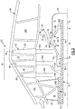
Figure 3 is a more detailed schematic view of an aft bearing arrangement illustrated inFigure 2 . -
Figure 1 schematically illustrates agas turbine engine 20. Thegas turbine engine 20 is disclosed herein as a two-spool turbofan that generally incorporates afan section 22, acompressor section 24, acombustor section 26 and aturbine section 28. Alternative engines might include an augmentor section (not shown) among other systems or features. Thefan section 22 drives air along a bypass flowpath while thecompressor section 24 drives air along a core flowpath for compression and communication into thecombustor section 26 then expansion through theturbine section 28. Although depicted as a turbofan gas turbine engine in the disclosed non-limiting embodiment, it should be understood that the concepts described herein are not limited to use with turbofans as the teachings may be applied to other types of turbine engines including three-spool architectures. - The
engine 20 generally includes alow speed spool 30 and ahigh speed spool 32 mounted for rotation about an engine central longitudinal axis A relative to an engine static structure orhousing 58 viaseveral bearing systems 38. It should be understood thatvarious bearing systems 38 at various locations may alternatively or additionally be provided. Thehousing 58 includes first, second, third, andfourth housing portions fourth housing portions - The
low speed spool 30 generally includes aninner shaft 40 that interconnects afan 42, alow pressure compressor 44 and alow pressure turbine 46. Theinner shaft 40 is connected to thefan 42 through a gearedarchitecture 48 to drive thefan 42 at a lower speed than thelow speed spool 30. Thehigh speed spool 32 includes anouter shaft 50 that interconnects ahigh pressure compressor 52 andhigh pressure turbine 54. Acombustor 56 is arranged between thehigh pressure compressor 52 and thehigh pressure turbine 54. Themid-turbine frame 58C of the enginestatic structure 58 is arranged generally between thehigh pressure turbine 54 and thelow pressure turbine 46. Themid-turbine frame 58C supports one ormore bearing systems 38 in theturbine section 28. Theturbine exhaust case 58D is arranged downstream from thelow pressure turbine 46 and may support one or more bearing systems as well. Theinner shaft 40 and theouter shaft 50 are concentric and rotate via bearingsystems 38 about the engine central longitudinal axis A, which is collinear with their longitudinal axes. - The core airflow is compressed by the
low pressure compressor 44 then thehigh pressure compressor 52, mixed and burned with fuel in thecombustor 56, then expanded over thehigh pressure turbine 54 andlow pressure turbine 46. Themid-turbine frame 58C includesairfoils 59 which are in the core airflow path. Theturbines low speed spool 30 andhigh speed spool 32 in response to the expansion. - The
engine 20 is, in one example, a high-bypass geared aircraft engine. In a further example, theengine 20 bypass ratio is greater than about six, with an example embodiment being greater than ten, the gearedarchitecture 48 is an epicyclic gear train, such as a planetary gear system or other gear system, with a gear reduction ratio of greater than about 2.3 and thelow pressure turbine 46 has a pressure ratio that is greater than about 5. In one disclosed embodiment, theengine 20 bypass ratio is greater than about ten, the fan diameter is significantly larger than that of thelow pressure compressor 44, and thelow pressure turbine 46 has a pressure ratio that is greater than about 5:1.Low pressure turbine 46 pressure ratio is pressure measured prior to inlet oflow pressure turbine 46 as related to the pressure at the outlet of thelow pressure turbine 46 prior to an exhaust nozzle. The gearedarchitecture 48 may be an epicycle gear train, such as a planetary gear system or other gear system, with a gear reduction ratio of greater than about 2.5:1. It should be understood, however, that the above parameters are only exemplary of one embodiment of a geared architecture engine and that the present invention is applicable to other gas turbine engines including direct drive turbofans. - A significant amount of thrust is provided by the bypass flow B due to the high bypass ratio. The
fan section 22 of theengine 20 is designed for a particular flight condition -- typically cruise at about 0.8 Mach and about 35,000 feet (10,668 m). The flight condition of 0.8 Mach and 35,000 ft (10,668 m), with the engine at its best fuel consumption - also known as "bucket cruise Thrust Specific Fuel Consumption ('TSFC')" - is the industry standard parameter of lbm of fuel being burned divided by lbf of thrust the engine produces at that minimum point. "Low fan pressure ratio" is the pressure ratio across the fan blade alone, without a Fan Exit Guide Vane ("FEGV") system. The low fan pressure ratio as disclosed herein according to one non-limiting embodiment is less than about 1.45. "Low corrected fan tip speed" is the actual fan tip speed in ft/sec divided by an industry standard temperature correction of [(Tram °R) / (518.7 °R)]0.5, where °R = 9/5 x K. The "Low corrected fan tip speed" as disclosed herein according to one non-limiting embodiment is less than about 1150 ft / second (350.5 m/s). - An example bearing arrangement for the
gas turbine engine 20 is schematically depicted inFigure 2 . Thelow speed spool 30 extends axially between forward and aft ends, with the aft end extending beyond thehigh speed spool 32. Thehigh speed spool 32 is supported for rotation by first andsecond bearings first bearing 38A is of a type that may react to both axial and radial loads, such as a ball bearing. Thesecond bearing 38B is of a type that reacts to radial loads, such as a roller bearing or a journal bearing. Thelow speed spool 30 is supported by first, second andthird bearings first bearing 38C is of a type that reacts to both axial and radial loads. The second andthird bearings third bearings low speed spool 30. - The
low speed spool 30 has a higher length/diameter (L/D) ratio than thehigh speed spool 32. From a rotor dynamics standpoint, a shaft will reach a critical speed of instability at a lower speed as the L/D ratio gets larger. Providing at least two bearings at the aft end of thelow speed spool 30 increases the critical speed of thelow speed spool 30, which enables higher overall engine speeds and lower weight thereby allowing theengine 20 to be faster and smaller for a given level of thrust. -
Figure 3 illustrates a more detailed view of theengine 20 shown inFigure 2 . Thesecond bearing 38B supporting thelow speed spool 30 is arranged within afirst bearing compartment 60. Thefirst bearing compartment 60 is provided by first andsecond walls second spool 30. - The
low pressure turbine 46 includes a low pressureturbine rotor hub 66 secured to thelow speed spool 30. The low pressureturbine rotor hub 66 supports multiple lowpressure turbine blades 68 in one example. Low pressureturbine stator vanes 70 are provided between the lowpressure turbine blades 68 and supported by the housing 16. The low pressureturbine rotor hub 66 is canted in an aft direction, which accommodates asecond bearing compartment 72. The second andthird bearings second bearing compartment 72, which is provided by first andsecond walls cover 84, for example. Thecover 84 is removably secured over the aft end and encloses the second andthird bearings - In the example, the
turbine exhaust case 58D includes a radially rearward cantedannular flange 76, which removably supports ahub 74 secured to theflange 76 byfasteners 78. Thehub 74 includes first andsecond hub walls annular apex 89 provided near theflange 76 in the example shown. In the example shown, the first andsecond hub walls second hub walls third bearings turbine rotor hub 66 accommodates at least thesecond bearing 38D and a portion of thefirst hub wall 86 is arranged radially beneath thelow pressure turbine 46 such that axial length need not be added to thelow speed spool 30. Thesecond bearing 38D is arranged axially forward of anaft side 98 of alast rotor stage 96. - In one example, the second and
third bearings first hub wall 86 is oriented at afirst angle 92 of between 30° and 60°, and thesecond hub wall 88 is oriented at asecond angle 94 of between 30° and 60°. Theannular flange 76 is oriented relative to thefirst hub wall 86 at athird angle 95 of between 0° and 30°, for example. In one example, thefirst angle 92 is about 45° and thethird angle 95 is about 0°. The above values are exemplary for one example engine design. - The multiple turbine rotors include first, second and
third turbine rotors last rotor stage 96. Thefirst turbine rotor 69A corresponds to a forward-most rotor stage. Thesecond turbine rotor 69B is arranged axially between the first andthird rotors turbine rotor hub 66 is mounted on thelow speed spool 30 and is secured to thesecond turbine hub 69B for supporting thelow pressure turbine 46. In one example, the bearinghub 74 includes a moment stiffness of 80,000,000 in-lb/rad (9,144,000 cm-kg/rad), for example, and a lateral stiffness of 5,000,000 lb/in (886,000 kg/cm). - Although example embodiments have been disclosed, a worker of ordinary skill in this art would recognize that certain modifications would come within the scope of the claims. For that reason, the following claims should be studied to determine their true scope and content.
Claims (15)
- A bearing hub (74) for a gas turbine engine (20) comprising:first and second hub walls (86, 88) integrally formed with one another to provide a unitary structure, the first and second hub walls (86, 88) inclined radially outward from an annular apex (89); andfirst and second bearings (38D, 38E) respectively supported by the first and second walls (86, 88) opposite the apex (89), wherein the first and second hub walls (86, 88) each are respectively oriented at first and second angles (92, 94) each of between 30° and 60° relative to an axis (A) of the bearing hub (74).
- The bearing hub according to claim 1, wherein the first and second bearings (38D, 38E) are roller bearings.
- The bearing hub according to claim 1 or 2, wherein the first and second angles (92, 94) are each about 45°.
- The bearing hub according to claim 1, 2 or 3, wherein the first and second bearings (38D, 38E) are configured to support an aft end of a low speed spool (30) of a gas turbine engine (20).
- A gas turbine engine (20) comprising:a fan (42);a compressor section (24) fluidly connected to the fan (42), the compressor section (24) comprising a high pressure compressor (52) and a low pressure compressor (44);a combustor (56) fluidly connected to the compressor section (24);a turbine section (28) fluidly connected to the combustor (56), the turbine section (28) comprising:a high pressure turbine (54) coupled to the high pressure compressor (52) via a shaft (50);a low pressure turbine (46);the bearing hub (74) of claim 1, 2 or 3, the first and second hub walls (86, 88) joined at the annular apex (89); anda turbine exhaust case (58D) arranged downstream from the low pressure turbine (46) supporting the annular apex (89).
- The gas turbine engine according to claim 5, wherein the gas turbine engine (20) includes a low Fan Pressure Ratio of less than about 1.45, and/or the low pressure turbine (46) has a pressure ratio that is greater than about 5.
- A gas turbine engine (20) comprising:a turbine (46, 54);a spool (30, 32) extending between forward and aft ends, the aft end supporting the turbine (46, 54);a housing portion (58D) arranged downstream from the turbine (46, 54); andfirst and second bearings (38D, 38E) mounted to the aft end of the spool (30, 32) and supported by the housing portion (58D),wherein the housing portion (58D) includes a bearing hub (74) removably secured to an annular flange (76), the first and second bearings (38D, 38E) are mounted to the bearing hub (74), the first and second bearings (38D, 38E) are arranged in a bearing compartment (72), the bearing hub (74) includes first and second hub walls (86, 88) respectively supporting the first and second bearings (38D, 38E), the first and second hub walls (86, 88) are inclined radially to the first and second bearings (38D, 38E) from an annular apex (89) at which the first and second hub walls (86, 88) are joined near the annular flange (76), and a portion of the first hub wall (86) is arranged radially beneath the turbine (46, 54), andwherein the first hub wall (86) is oriented at a first angle (92) of between 30° and 60° relative to a line parallel to the longitudinal axis (A), the second hub wall (88) is oriented at a second angle (94) of between 30° and 60° relative to a line parallel to the longitudinal axis (A), and the first and second hub walls (86,88) are canted toward one another in opposing directions and provide an integrated, unitary structure.
- The gas turbine engine according to claim 7, wherein the housing portion (58D) corresponds to a turbine exhaust case (58D).
- The gas turbine engine according to claim 7 or 8, wherein the spool (30, 32) is one of first and second spools (30, 32) coaxial with one another, the first spool (30) arranged within the second spool (32), and, optionally, the bearing compartment (72) is aft of the second spool (32).
- The gas turbine engine according to claim 9, comprising a combustor (56), and high and low pressure turbines (46, 54) downstream from the combustor (56), the high pressure turbine (54) mounted on the second spool (32), and the low pressure turbine (46) mounted on the first spool (30) and corresponding to the turbine, and, optionally, the low pressure turbine (46) has a pressure ratio that is greater than five.
- The gas turbine engine according to claim 10, wherein the low pressure turbine (46) includes multiple turbine rotors (69A, 69B, 69C), and the first bearing (38D) is arranged axially forward of an aft side (98) of a last rotor stage (96) of the low pressure turbine (46).
- The gas turbine engine according to claim 11, wherein the multiple turbine rotors (69A, 69B, 69C) include first, second and third turbine rotors (69A, 69B, 69C), the third turbine rotor (69C) corresponding to the last rotor stage (96), the first turbine rotor (69A) corresponding to a forward-most rotor stage, and the second turbine rotor (69B) arranged axially between the first and third rotors (69A, 69C), and comprising a low pressure turbine hub (66) mounted on the first spool (30) and secured to the second turbine rotor (69B) for supporting the multiple turbine rotors (69A, 69B, 69C).
- The gas turbine engine according to any of claims 7 to 12, wherein the first and second bearings (38D, 38E) are spaced apart from one another approximately four to twelve inches (10-30 cm).
- The gas turbine engine according to any of claims 7 to 13, wherein the annular flange (76) is oriented relative to the first hub wall (86) at a third angle (95) of between 0° and 30°, and, optionally, the first angle (92) is about 45° and the third angle (95) is about 0°.
- The gas turbine engine according to any of claims 5 to 14, wherein the gas turbine engine (20) is a high bypass geared aircraft engine having a bypass ratio of greater than about six.
Applications Claiming Priority (4)
| Application Number | Priority Date | Filing Date | Title |
|---|---|---|---|
| US201261593050P | 2012-01-31 | 2012-01-31 | |
| US13/364,502 US20130340435A1 (en) | 2012-01-31 | 2012-02-02 | Gas turbine engine aft spool bearing arrangement and hub wall configuration |
| PCT/US2013/020750 WO2013147977A1 (en) | 2012-01-31 | 2013-01-09 | Gas turbine engine aft bearing arrangement |
| EP13767684.7A EP2809902B1 (en) | 2012-01-31 | 2013-01-09 | Gas turbine engine aft bearing arrangement |
Related Parent Applications (1)
| Application Number | Title | Priority Date | Filing Date |
|---|---|---|---|
| EP13767684.7A Division EP2809902B1 (en) | 2012-01-31 | 2013-01-09 | Gas turbine engine aft bearing arrangement |
Publications (1)
| Publication Number | Publication Date |
|---|---|
| EP3907392A1 true EP3907392A1 (en) | 2021-11-10 |
Family
ID=49260979
Family Applications (2)
| Application Number | Title | Priority Date | Filing Date |
|---|---|---|---|
| EP21175715.8A Withdrawn EP3907392A1 (en) | 2012-01-31 | 2013-01-09 | Gas turbine engine aft bearing arrangement |
| EP13767684.7A Active EP2809902B1 (en) | 2012-01-31 | 2013-01-09 | Gas turbine engine aft bearing arrangement |
Family Applications After (1)
| Application Number | Title | Priority Date | Filing Date |
|---|---|---|---|
| EP13767684.7A Active EP2809902B1 (en) | 2012-01-31 | 2013-01-09 | Gas turbine engine aft bearing arrangement |
Country Status (3)
| Country | Link |
|---|---|
| US (2) | US20130340435A1 (en) |
| EP (2) | EP3907392A1 (en) |
| WO (1) | WO2013147977A1 (en) |
Families Citing this family (10)
| Publication number | Priority date | Publication date | Assignee | Title |
|---|---|---|---|---|
| US20160333786A1 (en) * | 2015-05-13 | 2016-11-17 | General Electric Company | System for supporting rotor shafts of an indirect drive turbofan engine |
| US10823064B2 (en) * | 2016-10-06 | 2020-11-03 | General Electric Company | Gas turbine engine |
| US10823001B2 (en) * | 2017-09-20 | 2020-11-03 | General Electric Company | Turbomachine with alternatingly spaced turbine rotor blades |
| FR3104192B1 (en) * | 2019-12-10 | 2022-07-15 | Safran Aircraft Engines | CONTRAROTATIVE TURBINE TURBOMACHINE FOR AN AIRCRAFT |
| GB201918782D0 (en) | 2019-12-19 | 2020-02-05 | Rolls Royce Plc | Shaft bearing arrangement |
| GB201918779D0 (en) * | 2019-12-19 | 2020-02-05 | Rolls Royce Plc | Shaft bearings |
| GB201918783D0 (en) | 2019-12-19 | 2020-02-05 | Rolls Royce Plc | Shaft with three bearings |
| GB201918780D0 (en) | 2019-12-19 | 2020-02-05 | Rolls Royce Plc | Shaft bearings for gas turbine engine |
| GB201918777D0 (en) * | 2019-12-19 | 2020-02-05 | Rolls Royce Plc | Shaft bearing arrangement |
| GB201918781D0 (en) * | 2019-12-19 | 2020-02-05 | Rolls Royce Plc | Improved shaft bearing positioning in a gas turbine engine |
Citations (5)
| Publication number | Priority date | Publication date | Assignee | Title |
|---|---|---|---|---|
| US3823553A (en) * | 1972-12-26 | 1974-07-16 | Gen Electric | Gas turbine with removable self contained power turbine module |
| US20060201160A1 (en) * | 2005-03-14 | 2006-09-14 | Rolls-Royce Plc | Multi-shaft arrangement for a turbine engine |
| US20080031727A1 (en) * | 2004-10-06 | 2008-02-07 | Volvo Aero Corporation | Bearing Support Structure and a Gas Turbine Engine Comprising the Bearing Support Structure |
| US20110030387A1 (en) * | 2006-04-04 | 2011-02-10 | United Technologies Corporation | Mid-turbine frame torque box having a concave surface |
| US20120017603A1 (en) * | 2009-04-17 | 2012-01-26 | Snecma | Double-body gas turbine engine provided with an inter-shaft bearing |
Family Cites Families (11)
| Publication number | Priority date | Publication date | Assignee | Title |
|---|---|---|---|---|
| US3722212A (en) * | 1971-03-04 | 1973-03-27 | Avco Corp | Gas turbine engine lubrication system |
| US4483149A (en) * | 1982-05-20 | 1984-11-20 | United Technologies Corporation | Diffuser case for a gas turbine engine |
| US6846158B2 (en) * | 2002-09-06 | 2005-01-25 | General Electric Company | Method and apparatus for varying the critical speed of a shaft |
| GB0406174D0 (en) * | 2004-03-19 | 2004-04-21 | Rolls Royce Plc | Turbine engine arrangement |
| US7097413B2 (en) * | 2004-05-12 | 2006-08-29 | United Technologies Corporation | Bearing support |
| US7610763B2 (en) * | 2006-05-09 | 2009-11-03 | United Technologies Corporation | Tailorable design configuration topologies for aircraft engine mid-turbine frames |
| US7594405B2 (en) * | 2006-07-27 | 2009-09-29 | United Technologies Corporation | Catenary mid-turbine frame design |
| US8209950B2 (en) * | 2006-10-12 | 2012-07-03 | United Technologies Corporation | Detecting ice buildup on an aircraft engine and actuating the turbofan exit nozzle to break the ice |
| US7942635B1 (en) * | 2007-08-02 | 2011-05-17 | Florida Turbine Technologies, Inc. | Twin spool rotor assembly for a small gas turbine engine |
| EP2479414B1 (en) * | 2007-08-08 | 2015-06-10 | Rohr, Inc. | Variable area fan nozzle with bypass flow |
| US8181441B2 (en) * | 2009-02-27 | 2012-05-22 | United Technologies Corporation | Controlled fan stream flow bypass |
-
2012
- 2012-02-02 US US13/364,502 patent/US20130340435A1/en not_active Abandoned
- 2012-08-06 US US13/567,178 patent/US20140060080A1/en not_active Abandoned
-
2013
- 2013-01-09 EP EP21175715.8A patent/EP3907392A1/en not_active Withdrawn
- 2013-01-09 EP EP13767684.7A patent/EP2809902B1/en active Active
- 2013-01-09 WO PCT/US2013/020750 patent/WO2013147977A1/en not_active Ceased
Patent Citations (5)
| Publication number | Priority date | Publication date | Assignee | Title |
|---|---|---|---|---|
| US3823553A (en) * | 1972-12-26 | 1974-07-16 | Gen Electric | Gas turbine with removable self contained power turbine module |
| US20080031727A1 (en) * | 2004-10-06 | 2008-02-07 | Volvo Aero Corporation | Bearing Support Structure and a Gas Turbine Engine Comprising the Bearing Support Structure |
| US20060201160A1 (en) * | 2005-03-14 | 2006-09-14 | Rolls-Royce Plc | Multi-shaft arrangement for a turbine engine |
| US20110030387A1 (en) * | 2006-04-04 | 2011-02-10 | United Technologies Corporation | Mid-turbine frame torque box having a concave surface |
| US20120017603A1 (en) * | 2009-04-17 | 2012-01-26 | Snecma | Double-body gas turbine engine provided with an inter-shaft bearing |
Also Published As
| Publication number | Publication date |
|---|---|
| US20140060080A1 (en) | 2014-03-06 |
| WO2013147977A1 (en) | 2013-10-03 |
| EP2809902A1 (en) | 2014-12-10 |
| EP2809902A4 (en) | 2015-10-14 |
| US20130340435A1 (en) | 2013-12-26 |
| EP2809902B1 (en) | 2021-05-26 |
Similar Documents
| Publication | Publication Date | Title |
|---|---|---|
| EP2809890B1 (en) | Gas turbine engine bearing arrangement | |
| EP3473834B1 (en) | Gas turbine engine shaft bearing configuration | |
| EP2809902B1 (en) | Gas turbine engine aft bearing arrangement | |
| US11149689B2 (en) | Gas turbine engine shaft bearing configuration | |
| EP2877725B1 (en) | Geared fan with inner counter rotating compressor | |
| EP3372782B1 (en) | Vaneless counterrotating turbine | |
| EP3036416B1 (en) | High thrust geared gas turbine engine | |
| US9194290B2 (en) | Counter-rotating low pressure turbine without turbine exhaust case | |
| EP3036410B1 (en) | Integral gutter and front center body | |
| US10060291B2 (en) | Mid-turbine frame rod and turbine case flange | |
| US20150089959A1 (en) | Gas turbine engine shaft bearing configuration | |
| EP3054141B1 (en) | Gear reduction for geared turbofan | |
| WO2014058455A1 (en) | Bearing support stiffness control | |
| EP3036420B1 (en) | Load balanced journal bearing pin | |
| EP2809937B1 (en) | Gas turbine engine shaft bearing arrangement | |
| EP3081768B1 (en) | Gas turbine engine shaft bearing configuration | |
| EP3084142B1 (en) | Shortened support for compressor variable vane |
Legal Events
| Date | Code | Title | Description |
|---|---|---|---|
| PUAI | Public reference made under article 153(3) epc to a published international application that has entered the european phase |
Free format text: ORIGINAL CODE: 0009012 |
|
| STAA | Information on the status of an ep patent application or granted ep patent |
Free format text: STATUS: THE APPLICATION HAS BEEN PUBLISHED |
|
| AC | Divisional application: reference to earlier application |
Ref document number: 2809902 Country of ref document: EP Kind code of ref document: P |
|
| AK | Designated contracting states |
Kind code of ref document: A1 Designated state(s): AL AT BE BG CH CY CZ DE DK EE ES FI FR GB GR HR HU IE IS IT LI LT LU LV MC MK MT NL NO PL PT RO RS SE SI SK SM TR |
|
| B565 | Issuance of search results under rule 164(2) epc |
Effective date: 20211008 |
|
| STAA | Information on the status of an ep patent application or granted ep patent |
Free format text: STATUS: REQUEST FOR EXAMINATION WAS MADE |
|
| 17P | Request for examination filed |
Effective date: 20220510 |
|
| RBV | Designated contracting states (corrected) |
Designated state(s): AL AT BE BG CH CY CZ DE DK EE ES FI FR GB GR HR HU IE IS IT LI LT LU LV MC MK MT NL NO PL PT RO RS SE SI SK SM TR |
|
| RAP3 | Party data changed (applicant data changed or rights of an application transferred) |
Owner name: RTX CORPORATION |
|
| STAA | Information on the status of an ep patent application or granted ep patent |
Free format text: STATUS: EXAMINATION IS IN PROGRESS |
|
| 17Q | First examination report despatched |
Effective date: 20231103 |
|
| STAA | Information on the status of an ep patent application or granted ep patent |
Free format text: STATUS: THE APPLICATION IS DEEMED TO BE WITHDRAWN |
|
| 18D | Application deemed to be withdrawn |
Effective date: 20240504 |