EP3907376A1 - Shrouded aircraft engine seal carrier - Google Patents
Shrouded aircraft engine seal carrier Download PDFInfo
- Publication number
- EP3907376A1 EP3907376A1 EP21172338.2A EP21172338A EP3907376A1 EP 3907376 A1 EP3907376 A1 EP 3907376A1 EP 21172338 A EP21172338 A EP 21172338A EP 3907376 A1 EP3907376 A1 EP 3907376A1
- Authority
- EP
- European Patent Office
- Prior art keywords
- carrier
- tab
- seal
- rotation inhibiting
- seal configuration
- Prior art date
- Legal status (The legal status is an assumption and is not a legal conclusion. Google has not performed a legal analysis and makes no representation as to the accuracy of the status listed.)
- Granted
Links
Images
Classifications
-
- F—MECHANICAL ENGINEERING; LIGHTING; HEATING; WEAPONS; BLASTING
- F01—MACHINES OR ENGINES IN GENERAL; ENGINE PLANTS IN GENERAL; STEAM ENGINES
- F01D—NON-POSITIVE DISPLACEMENT MACHINES OR ENGINES, e.g. STEAM TURBINES
- F01D11/00—Preventing or minimising internal leakage of working-fluid, e.g. between stages
- F01D11/003—Preventing or minimising internal leakage of working-fluid, e.g. between stages by packing rings; Mechanical seals
-
- F—MECHANICAL ENGINEERING; LIGHTING; HEATING; WEAPONS; BLASTING
- F16—ENGINEERING ELEMENTS AND UNITS; GENERAL MEASURES FOR PRODUCING AND MAINTAINING EFFECTIVE FUNCTIONING OF MACHINES OR INSTALLATIONS; THERMAL INSULATION IN GENERAL
- F16J—PISTONS; CYLINDERS; SEALINGS
- F16J15/00—Sealings
- F16J15/16—Sealings between relatively-moving surfaces
- F16J15/34—Sealings between relatively-moving surfaces with slip-ring pressed against a more or less radial face on one member
- F16J15/36—Sealings between relatively-moving surfaces with slip-ring pressed against a more or less radial face on one member connected by a diaphragm or bellow to the other member
- F16J15/363—Sealings between relatively-moving surfaces with slip-ring pressed against a more or less radial face on one member connected by a diaphragm or bellow to the other member the diaphragm or bellow being made of metal
-
- F—MECHANICAL ENGINEERING; LIGHTING; HEATING; WEAPONS; BLASTING
- F01—MACHINES OR ENGINES IN GENERAL; ENGINE PLANTS IN GENERAL; STEAM ENGINES
- F01D—NON-POSITIVE DISPLACEMENT MACHINES OR ENGINES, e.g. STEAM TURBINES
- F01D25/00—Component parts, details, or accessories, not provided for in, or of interest apart from, other groups
- F01D25/18—Lubricating arrangements
- F01D25/183—Sealing means
-
- F—MECHANICAL ENGINEERING; LIGHTING; HEATING; WEAPONS; BLASTING
- F05—INDEXING SCHEMES RELATING TO ENGINES OR PUMPS IN VARIOUS SUBCLASSES OF CLASSES F01-F04
- F05D—INDEXING SCHEME FOR ASPECTS RELATING TO NON-POSITIVE-DISPLACEMENT MACHINES OR ENGINES, GAS-TURBINES OR JET-PROPULSION PLANTS
- F05D2260/00—Function
- F05D2260/30—Retaining components in desired mutual position
- F05D2260/36—Retaining components in desired mutual position by a form fit connection, e.g. by interlocking
-
- F—MECHANICAL ENGINEERING; LIGHTING; HEATING; WEAPONS; BLASTING
- F05—INDEXING SCHEMES RELATING TO ENGINES OR PUMPS IN VARIOUS SUBCLASSES OF CLASSES F01-F04
- F05D—INDEXING SCHEME FOR ASPECTS RELATING TO NON-POSITIVE-DISPLACEMENT MACHINES OR ENGINES, GAS-TURBINES OR JET-PROPULSION PLANTS
- F05D2260/00—Function
- F05D2260/30—Retaining components in desired mutual position
- F05D2260/38—Retaining components in desired mutual position by a spring, i.e. spring loaded or biased towards a certain position
Definitions
- the present disclosure relates generally to aircraft engine seals, and more particularly to a shrouded aircraft engine seal.
- Gas turbine engines such as those utilized in commercial and military aircraft, include a compressor section that compresses air, a combustor section in which the compressed air is mixed with a fuel and ignited, and a turbine section across which the resultant combustion products are expanded.
- the expansion of the combustion products drives the turbine section to rotate.
- the turbine section is connected to the compressor section via a shaft, the rotation of the turbine section further drives the compressor section to rotate.
- a fan is also connected to the shaft and is driven to rotate via rotation of the turbine as well.
- Some such seals are carbon seals and include a stationary sealing component in contact with an adjacent rotating component.
- portions of the seal housing that maintain the seal in a stationary state can become disconnected resulting in a system where rotation of the adjacent component can be translated to the seal element, resulting in the seal element being driven to rotate. While certain sealing configurations are resistant to this undesirable rotation, failure modes in which the rotation can occur remain possible.
- a seal configuration for an aircraft engine includes a ring shaped sealing component defining an axis, a carrier disposed radially outward of the ring shaped sealing component and supporting the ring shaped sealing component, a housing including a shroud portion, the shroud portion fully surrounding the carrier, wherein the housing is maintained in a static position relative to the carrier via a bellows spring, and a plurality of rotation inhibiting features, each rotation inhibiting feature in the plurality of rotation inhibiting features including a tab protruding radially outward from the carrier and received in a slot intruding into the shroud portion.
- the plurality of rotation inhibiting features are disposed in a radially balanced configuration.
- each tab is positioned at an axial end of the carrier.
- the axial end of the carrier is an axial end nearest the bellows spring.
- the tab is maintained out of contact with slot surfaces while the seal configuration is in a non-failed state.
- the plurality of rotation inhibiting features includes at least three rotation inhibiting features.
- the plurality of rotation inhibiting features includes at least four rotation inhibiting features.
- the ring shaped sealing component includes an axial protrusion at a first axial end of the ring shaped sealing component.
- the axial protrusion extends beyond an axial end of the shroud portion.
- each slot has an axial length such that the corresponding tab is out of contact with an axial end of the slot while the bellows spring is in a fully compressed state.
- a gas turbine engine includes a compressor section, a combustor section fluidly connected to the compressor section, and a turbine section fluidly connected to the combustor section, and a plurality of seals disposed within the gas turbine engine.
- Each of the seals including: a ring shaped sealing component defining an axis, a carrier disposed radially outward of the ring shaped sealing component and supporting the ring shaped sealing component, a housing including a shroud portion, the shroud portion fully surrounding the carrier, wherein the housing is maintained in a static position relative to the carrier via a bellows spring, and a plurality of rotation inhibiting features, each rotation inhibiting feature in the plurality of rotation inhibiting features including a tab protruding radially outward from the carrier and received in a slot intruding into the shroud portion.
- At least one of the seals in the plurality of seals is disposed proximate a bearing.
- the plurality of rotation inhibiting features are disposed in a radially balanced configuration.
- the plurality of rotation inhibiting features includes from two to four rotation inhibiting features.
- An exemplary method for preventing rotation of a seal element includes allowing at least a portion of a carrier to rotate until a radially outward protruding tab of the carrier contacts a shroud and preventing continued rotation of the seal element via interfacing a tab protruding radially outward from the carrier and a slot wall of the shroud.
- Another example of the above described method for preventing rotation of a seal element further includes preventing contact between the tab and the shroud while a bellows spring is in a non-failed state.
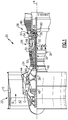
- FIG. 1 schematically illustrates a gas turbine engine 20.
- the gas turbine engine 20 is disclosed herein as a two-spool turbofan that generally incorporates a fan section 22, a compressor section 24, a combustor section 26 and a turbine section 28.
- Alternative engines might include an augmentor section (not shown) among other systems or features.
- the fan section 22 drives air along a bypass flow path B in a bypass duct defined within a nacelle 15, and also drives air along a core flow path C for compression and communication into the combustor section 26 then expansion through the turbine section 28.
- the exemplary engine 20 generally includes a low speed spool 30 and a high speed spool 32 mounted for rotation about an engine central longitudinal axis A relative to an engine static structure 36 via several bearing systems 38. It should be understood that various bearing systems 38 at various locations may alternatively or additionally be provided, and the location of bearing systems 38 may be varied as appropriate to the application.
- the low speed spool 30 generally includes an inner shaft 40 that interconnects a fan 42, a first (or low) pressure compressor 44 and a first (or low) pressure turbine 46.
- the inner shaft 40 is connected to the fan 42 through a speed change mechanism, which in exemplary gas turbine engine 20 is illustrated as a geared architecture 48 to drive the fan 42 at a lower speed than the low speed spool 30.
- the high speed spool 32 includes an outer shaft 50 that interconnects a second (or high) pressure compressor 52 and a second (or high) pressure turbine 54.
- a combustor 56 is arranged in exemplary gas turbine engine 20 between the high pressure compressor 52 and the high pressure turbine 54.
- a mid-turbine frame 57 of the engine static structure 36 is arranged generally between the high pressure turbine 54 and the low pressure turbine 46.
- the mid-turbine frame 57 further supports bearing systems 38 in the turbine section 28.
- the inner shaft 40 and the outer shaft 50 are concentric and rotate via bearing systems 38 about the engine central longitudinal axis A which is collinear with their longitudinal axes.
- the core airflow is compressed by the low pressure compressor 44 then the high pressure compressor 52, mixed and burned with fuel in the combustor 56, then expanded over the high pressure turbine 54 and low pressure turbine 46.
- the mid-turbine frame 57 includes airfoils 59 which are in the core airflow path C.
- the turbines 46, 54 rotationally drive the respective low speed spool 30 and high speed spool 32 in response to the expansion.
- gear system 48 may be located aft of combustor section 26 or even aft of turbine section 28, and fan section 22 may be positioned forward or aft of the location of gear system 48.
- the engine 20 in one example is a high-bypass geared aircraft engine.
- the engine 20 bypass ratio is greater than about six (6), with an example embodiment being greater than about ten (10)
- the geared architecture 48 is an epicyclic gear train, such as a planetary gear system or other gear system, with a gear reduction ratio of greater than about 2.3
- the low pressure turbine 46 has a pressure ratio that is greater than about five.
- the engine 20 bypass ratio is greater than about ten (10:1)
- the fan diameter is significantly larger than that of the low pressure compressor 44
- the low pressure turbine 46 has a pressure ratio that is greater than about five 5:1.
- Low pressure turbine 46 pressure ratio is pressure measured prior to inlet of low pressure turbine 46 as related to the pressure at the outlet of the low pressure turbine 46 prior to an exhaust nozzle.
- the geared architecture 48 may be an epicycle gear train, such as a planetary gear system or other gear system, with a gear reduction ratio of greater than about 2.3:1. It should be understood, however, that the above parameters are only exemplary of one embodiment of a geared architecture engine and that the present invention is applicable to other gas turbine engines including direct drive turbofans.
- the fan section 22 of the engine 20 is designed for a particular flight condition -- typically cruise at about 0.8 Mach and about 35,000 feet (10,668 meters).
- the flight condition of 0.8 Mach and 35,000 ft (10,668 meters), with the engine at its best fuel consumption - also known as "bucket cruise Thrust Specific Fuel Consumption ('TSFC')" - is the industry standard parameter of lbm of fuel being burned divided by lbf of thrust the engine produces at that minimum point.
- "Low fan pressure ratio” is the pressure ratio across the fan blade alone, without a Fan Exit Guide Vane (“FEGV”) system.
- the low fan pressure ratio as disclosed herein according to one non-limiting embodiment is less than about 1.45.
- the "Low corrected fan tip speed” as disclosed herein according to one non-limiting embodiment is less than about 1150 ft / second (350.5 meters/second).
- Each of the seal locations 60 includes a stationary carbon seal disposed against an adjacent rotating engine part. While illustrated at three locations in the exemplary engine 20 of Figure 1 , one of skill in the art will appreciate that the number, and location, of the carbon seals will vary depending on the specific configuration of the given engine according to the needs of the engine.
- Some carbon seal designs utilize a bellows spring configuration to apply an axial load to the carbon seal face, thereby maintaining a sealing element in a stationary position relative to the rotating component contacting the sealing element. Due to vibrations induced by engine operations, or other external occurrences, the bellows spring can be excited and fail. When such a failure occurs, it is possible for the failure to occur at the weld points, resulting in a portion of the bellows spring becoming decoupled from the seal housing. The decoupling allows the decoupled portion of the bellows spring and the corresponding seal element to rotate along with the adjacent component.
- Such a rotation is undesirable and can result in a loss of centering of the seal element, damage to the seal element, the seal carrier, and further damage to the bellows spring, debris entering the sealed compartment and placing other hardware at risk, as well as potentially allowing oil to pass through the seal and contaminating an adjacent area.
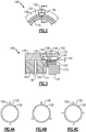
- Figure 2 schematically illustrates an axial end partial view of an exemplary seal configuration 100.
- Figure 3 schematically illustrates a cross sectional view along cross section A-A of the exemplary seal configuration 100 of Figure 2 .
- the seal configuration 100 includes a ring shaped seal element 110.
- axis and “radius” refers to an axis and a radius defined by the ring shaped element 110.
- the ring shaped seal element 110 can, in some examples, be a carbon seal.
- the ring shaped seal element 110 is mounted within a carrier 120.
- a housing 130 is disposed radially outward of the carrier 120, and is maintained in position relative to an engine static structure via any known static housing connection.
- the housing 130 is coupled to the carrier 120 via a bellows spring 140 (hidden in Figure 2 , visible in Figure 3 ). Also included in the housing 130 is a shroud portion 132.
- the shroud portion 132 is radially outward of, and radially surrounds, the carrier 120 and a majority of the seal element 110 with an axial extension 112 of the seal element 110 extending axially beyond an axial end 133 of the shroud portion 132.
- a first portion 142 of the bellows spring 140 can be decoupled from a second portion 144 of the bellows spring 140, allowing the second portion 144, and thus the carrier 120 and the seal element 110, to rotate about the axis.
- the illustrated bellows spring 140 of Figure 3 is depicted in such a failure mode.
- the illustrated failure mode includes a second portion 144 decoupled from a first portion 142, the features further described herein can be applicable to any failure mode that would allow the carrier 120 and the seal element 110 to rotate about the axis.
- the seal configuration 100 includes a slot 134 in the shroud 132 portion of the housing 130.
- the slot 134 is a radial intrusion into the shroud portion 132 and has an axial length such that the tab is maintained out of contact with an axial end of the slot 134 while the bellows spring 140 is in a fully compressed state.
- Received in the slot 134 is a radially outward extending protrusion 122 of the carrier 120.
- the radially outward extending protrusion is disposed at an axial end 124 of the carrier 120.
- a gap 141 is defined between a radially outward facing surface of the carrier 120 and a radially inward facing surface of the shroud portion 132.
- the gap 134 is a tightly controlled gap, thereby further maintaining performance of the shrouded seal.
- the radial gap 134 operates as an enclosure to entrap viscous fluid around the bellows spring 140, and as a radial pilot/deflection limiter.
- the radially outward protrusion 122 (alternately referred to as a tab) is received in the slot 134 without contacting the interior walls of the slot 134 during normal operations of the seal configuration 100.
- the carrier 120 rotates slightly until the radially outward protrusion 122 contacts a side surface 135 of the slot 134.
- Axially adjacent to the radial protrusion 122 is a radial intrusion 126.
- the radial intrusion intrudes into the seal carrier 120.
- the intrusion assists in manufacturing of the seal carrier 120.
- the radial intrusion 126 can be omitted and the radially outward facing surface of the seal carrier is uninterrupted from the radial protrusion 122 to the axial end opposite the radial protrusion 122.
- Also included on the carrier 120 is an interface tab 125.
- the interface tab 125 interfaces the carrier 120 with the bellows spring 140.
- the seal configuration 100 is able to prevent rotation of the carbon seal 120 in the event of a bellows fracture.
- the shrouded portion 132 provides a circumferentially controlled radial gap 141 that limits movement of the carbon carrier 120 composite and prevents the progression of unstable dynamic modes, which have been shown to contribute to bellows failure and carbon damage.
- the shroud portion 132 provides viscous damping to the overall seal configuration 100 without substantially impacting the sealing performance.
- the radial protrusions 122, and corresponding slots 134 are evenly distributed around the circumference of the carbon seal 110.
- Figures 4A, 4B, and 4C illustrate highly schematic views of the carrier 120 and the housing 130.
- the carrier 120 includes two radially outward protrusions 122.
- the carrier 120 includes three radially outward protrusions 122.
- the carrier 120 includes four radially outward protrusions 122. It is appreciated that in alternative examples, alternative numbers of circumferentially evenly distributed radially outward protrusions and slots can be utilized to similar effect and are within the bounds of this disclosure.
Landscapes
- Engineering & Computer Science (AREA)
- General Engineering & Computer Science (AREA)
- Mechanical Engineering (AREA)
- Chemical & Material Sciences (AREA)
- Combustion & Propulsion (AREA)
- Sealing Using Fluids, Sealing Without Contact, And Removal Of Oil (AREA)
- Structures Of Non-Positive Displacement Pumps (AREA)
Abstract
Description
- The present disclosure relates generally to aircraft engine seals, and more particularly to a shrouded aircraft engine seal.
- Gas turbine engines, such as those utilized in commercial and military aircraft, include a compressor section that compresses air, a combustor section in which the compressed air is mixed with a fuel and ignited, and a turbine section across which the resultant combustion products are expanded. The expansion of the combustion products drives the turbine section to rotate. As the turbine section is connected to the compressor section via a shaft, the rotation of the turbine section further drives the compressor section to rotate. In some examples, a fan is also connected to the shaft and is driven to rotate via rotation of the turbine as well.
- Included within the gas turbine engine at multiple locations, such as at bearing supports, are multiple engine seals. Some such seals are carbon seals and include a stationary sealing component in contact with an adjacent rotating component. In certain failure modes, portions of the seal housing that maintain the seal in a stationary state can become disconnected resulting in a system where rotation of the adjacent component can be translated to the seal element, resulting in the seal element being driven to rotate. While certain sealing configurations are resistant to this undesirable rotation, failure modes in which the rotation can occur remain possible.
- In one exemplary embodiment a seal configuration for an aircraft engine includes a ring shaped sealing component defining an axis, a carrier disposed radially outward of the ring shaped sealing component and supporting the ring shaped sealing component, a housing including a shroud portion, the shroud portion fully surrounding the carrier, wherein the housing is maintained in a static position relative to the carrier via a bellows spring, and a plurality of rotation inhibiting features, each rotation inhibiting feature in the plurality of rotation inhibiting features including a tab protruding radially outward from the carrier and received in a slot intruding into the shroud portion.
- In another example of the above described seal configuration for an aircraft engine the plurality of rotation inhibiting features are disposed in a radially balanced configuration.
- In another example of any of the above described seal configurations for an aircraft engine each tab is positioned at an axial end of the carrier.
- In another example of any of the above described seal configurations the axial end of the carrier is an axial end nearest the bellows spring.
- In another example of any of the above described seal configurations the tab is maintained out of contact with slot surfaces while the seal configuration is in a non-failed state.
- In another example of any of the above described seal configurations the plurality of rotation inhibiting features includes at least three rotation inhibiting features.
- In another example of any of the above described seal configurations the plurality of rotation inhibiting features includes at least four rotation inhibiting features.
- In another example of any of the above described seal configurations the ring shaped sealing component includes an axial protrusion at a first axial end of the ring shaped sealing component.
- In another example of any of the above described seal configurations the axial protrusion extends beyond an axial end of the shroud portion.
- In another example of any of the above described seal configurations each slot has an axial length such that the corresponding tab is out of contact with an axial end of the slot while the bellows spring is in a fully compressed state.
- In one exemplary embodiment a gas turbine engine includes a compressor section, a combustor section fluidly connected to the compressor section, and a turbine section fluidly connected to the combustor section, and a plurality of seals disposed within the gas turbine engine. Each of the seals including: a ring shaped sealing component defining an axis, a carrier disposed radially outward of the ring shaped sealing component and supporting the ring shaped sealing component, a housing including a shroud portion, the shroud portion fully surrounding the carrier, wherein the housing is maintained in a static position relative to the carrier via a bellows spring, and a plurality of rotation inhibiting features, each rotation inhibiting feature in the plurality of rotation inhibiting features including a tab protruding radially outward from the carrier and received in a slot intruding into the shroud portion.
- In another example of the above described gas turbine engine at least one of the seals in the plurality of seals is disposed proximate a bearing.
- In another example of any of the above described gas turbine engines the plurality of rotation inhibiting features are disposed in a radially balanced configuration.
- In another example of any of the above described gas turbine engines the plurality of rotation inhibiting features includes from two to four rotation inhibiting features.
- An exemplary method for preventing rotation of a seal element includes allowing at least a portion of a carrier to rotate until a radially outward protruding tab of the carrier contacts a shroud and preventing continued rotation of the seal element via interfacing a tab protruding radially outward from the carrier and a slot wall of the shroud.
- In another example of the above described method for preventing rotation of a seal element interfacing the tab and the slot wall comprises using the slot wall to oppose circumferential rotation of the tab.
- Another example of the above described method for preventing rotation of a seal element further includes preventing contact between the tab and the shroud while a bellows spring is in a non-failed state.
- These and other features of the present invention can be best understood from the following specification and drawings, the following of which is a brief description.
-
-
Figure 1 illustrates a high level schematic view of an exemplary gas turbine engine. -
Figure 2 schematically illustrates a partial axial end view of an exemplary seal configuration. -
Figure 3 schematically illustrates a cross sectional view along cross section A-A of the exemplary seal configuration ofFigure 2 . -
Figure 4A illustrates a highly schematic seal carrier configuration including a first example arrangement of anti-rotation features. -
Figure 4B illustrates a highly schematic seal carrier configuration including a second example arrangement of anti-rotation features. -
Figure 4C illustrates a highly schematic seal carrier configuration including a third example arrangement of anti-rotation features. -
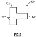
Figure 5 schematically illustrates an alternative example seal carrier for utilization in the seal configuration ofFigures 2 and 3 . -
Figure 1 schematically illustrates agas turbine engine 20. Thegas turbine engine 20 is disclosed herein as a two-spool turbofan that generally incorporates afan section 22, acompressor section 24, a combustor section 26 and aturbine section 28. Alternative engines might include an augmentor section (not shown) among other systems or features. Thefan section 22 drives air along a bypass flow path B in a bypass duct defined within anacelle 15, and also drives air along a core flow path C for compression and communication into the combustor section 26 then expansion through theturbine section 28. Although depicted as a two-spool turbofan gas turbine engine in the disclosed non-limiting embodiment, it should be understood that the concepts described herein are not limited to use with two-spool turbofans as the teachings may be applied to other types of turbine engines including three-spool architectures. - The
exemplary engine 20 generally includes alow speed spool 30 and ahigh speed spool 32 mounted for rotation about an engine central longitudinal axis A relative to an enginestatic structure 36 viaseveral bearing systems 38. It should be understood thatvarious bearing systems 38 at various locations may alternatively or additionally be provided, and the location ofbearing systems 38 may be varied as appropriate to the application. - The
low speed spool 30 generally includes aninner shaft 40 that interconnects afan 42, a first (or low)pressure compressor 44 and a first (or low)pressure turbine 46. Theinner shaft 40 is connected to thefan 42 through a speed change mechanism, which in exemplarygas turbine engine 20 is illustrated as a gearedarchitecture 48 to drive thefan 42 at a lower speed than thelow speed spool 30. Thehigh speed spool 32 includes anouter shaft 50 that interconnects a second (or high)pressure compressor 52 and a second (or high)pressure turbine 54. Acombustor 56 is arranged in exemplarygas turbine engine 20 between thehigh pressure compressor 52 and thehigh pressure turbine 54. Amid-turbine frame 57 of the enginestatic structure 36 is arranged generally between thehigh pressure turbine 54 and thelow pressure turbine 46. Themid-turbine frame 57 further supports bearingsystems 38 in theturbine section 28. Theinner shaft 40 and theouter shaft 50 are concentric and rotate viabearing systems 38 about the engine central longitudinal axis A which is collinear with their longitudinal axes. - The core airflow is compressed by the
low pressure compressor 44 then thehigh pressure compressor 52, mixed and burned with fuel in thecombustor 56, then expanded over thehigh pressure turbine 54 andlow pressure turbine 46. Themid-turbine frame 57 includesairfoils 59 which are in the core airflow path C. Theturbines low speed spool 30 andhigh speed spool 32 in response to the expansion. It will be appreciated that each of the positions of thefan section 22,compressor section 24, combustor section 26,turbine section 28, and fandrive gear system 48 may be varied. For example,gear system 48 may be located aft of combustor section 26 or even aft ofturbine section 28, andfan section 22 may be positioned forward or aft of the location ofgear system 48. - The
engine 20 in one example is a high-bypass geared aircraft engine. In a further example, theengine 20 bypass ratio is greater than about six (6), with an example embodiment being greater than about ten (10), the gearedarchitecture 48 is an epicyclic gear train, such as a planetary gear system or other gear system, with a gear reduction ratio of greater than about 2.3 and thelow pressure turbine 46 has a pressure ratio that is greater than about five. In one disclosed embodiment, theengine 20 bypass ratio is greater than about ten (10:1), the fan diameter is significantly larger than that of thelow pressure compressor 44, and thelow pressure turbine 46 has a pressure ratio that is greater than about five 5:1.Low pressure turbine 46 pressure ratio is pressure measured prior to inlet oflow pressure turbine 46 as related to the pressure at the outlet of thelow pressure turbine 46 prior to an exhaust nozzle. The gearedarchitecture 48 may be an epicycle gear train, such as a planetary gear system or other gear system, with a gear reduction ratio of greater than about 2.3:1. It should be understood, however, that the above parameters are only exemplary of one embodiment of a geared architecture engine and that the present invention is applicable to other gas turbine engines including direct drive turbofans. - A significant amount of thrust is provided by the bypass flow B due to the high bypass ratio. The
fan section 22 of theengine 20 is designed for a particular flight condition -- typically cruise at about 0.8 Mach and about 35,000 feet (10,668 meters). The flight condition of 0.8 Mach and 35,000 ft (10,668 meters), with the engine at its best fuel consumption - also known as "bucket cruise Thrust Specific Fuel Consumption ('TSFC')" - is the industry standard parameter of lbm of fuel being burned divided by lbf of thrust the engine produces at that minimum point. "Low fan pressure ratio" is the pressure ratio across the fan blade alone, without a Fan Exit Guide Vane ("FEGV") system. The low fan pressure ratio as disclosed herein according to one non-limiting embodiment is less than about 1.45. "Low corrected fan tip speed" is the actual fan tip speed in ft/sec divided by an industry standard temperature correction of [(Tram °R) / (518.7°R)]0.5 (where °R = K x 9/5). The "Low corrected fan tip speed" as disclosed herein according to one non-limiting embodiment is less than about 1150 ft / second (350.5 meters/second). - Included within the
engine 20 aremultiple seal locations 60 at or near the engine bearings. Each of theseal locations 60 includes a stationary carbon seal disposed against an adjacent rotating engine part. While illustrated at three locations in theexemplary engine 20 ofFigure 1 , one of skill in the art will appreciate that the number, and location, of the carbon seals will vary depending on the specific configuration of the given engine according to the needs of the engine. - Some carbon seal designs utilize a bellows spring configuration to apply an axial load to the carbon seal face, thereby maintaining a sealing element in a stationary position relative to the rotating component contacting the sealing element. Due to vibrations induced by engine operations, or other external occurrences, the bellows spring can be excited and fail. When such a failure occurs, it is possible for the failure to occur at the weld points, resulting in a portion of the bellows spring becoming decoupled from the seal housing. The decoupling allows the decoupled portion of the bellows spring and the corresponding seal element to rotate along with the adjacent component. Such a rotation is undesirable and can result in a loss of centering of the seal element, damage to the seal element, the seal carrier, and further damage to the bellows spring, debris entering the sealed compartment and placing other hardware at risk, as well as potentially allowing oil to pass through the seal and contaminating an adjacent area.
- Additionally, elevated or unanticipated inputs from the system, such as unexpected vibrations and jerks, can cause high stresses within the bellows spring itself. If left uncontrolled, these issues can lead to excessive carbon seal wear or bellows fracture. This can, in turn, result in a loss of compartment sealing capability, damage to surrounding engine hardware, and other potential issues for the system.
- With continued reference to
Figure 1 ,Figure 2 schematically illustrates an axial end partial view of anexemplary seal configuration 100.Figure 3 schematically illustrates a cross sectional view along cross section A-A of theexemplary seal configuration 100 ofFigure 2 . Theseal configuration 100 includes a ring shapedseal element 110. As used herein, reference to the "axis" and "radius" refers to an axis and a radius defined by the ring shapedelement 110. The ring shapedseal element 110 can, in some examples, be a carbon seal. The ring shapedseal element 110 is mounted within acarrier 120. Ahousing 130 is disposed radially outward of thecarrier 120, and is maintained in position relative to an engine static structure via any known static housing connection. Thehousing 130 is coupled to thecarrier 120 via a bellows spring 140 (hidden inFigure 2 , visible inFigure 3 ). Also included in thehousing 130 is ashroud portion 132. Theshroud portion 132 is radially outward of, and radially surrounds, thecarrier 120 and a majority of theseal element 110 with anaxial extension 112 of theseal element 110 extending axially beyond anaxial end 133 of theshroud portion 132. - In situations where the bellows spring 140 encounters a failure mode, a
first portion 142 of thebellows spring 140 can be decoupled from a second portion 144 of thebellows spring 140, allowing the second portion 144, and thus thecarrier 120 and theseal element 110, to rotate about the axis. The illustrated bellowsspring 140 ofFigure 3 is depicted in such a failure mode. Further, while the illustrated failure mode includes a second portion 144 decoupled from afirst portion 142, the features further described herein can be applicable to any failure mode that would allow thecarrier 120 and theseal element 110 to rotate about the axis. - In order to prevent the undesirable rotation, and thus minimize the negative impact of the failure mode, the
seal configuration 100 includes aslot 134 in theshroud 132 portion of thehousing 130. Theslot 134 is a radial intrusion into theshroud portion 132 and has an axial length such that the tab is maintained out of contact with an axial end of theslot 134 while thebellows spring 140 is in a fully compressed state. Received in theslot 134 is a radially outward extendingprotrusion 122 of thecarrier 120. In the example ofFigures 2 and 3 , the radially outward extending protrusion is disposed at anaxial end 124 of thecarrier 120. Agap 141 is defined between a radially outward facing surface of thecarrier 120 and a radially inward facing surface of theshroud portion 132. Thegap 134 is a tightly controlled gap, thereby further maintaining performance of the shrouded seal. During operation of the engine including theseal configuration 100, theradial gap 134 operates as an enclosure to entrap viscous fluid around thebellows spring 140, and as a radial pilot/deflection limiter. - The radially outward protrusion 122 (alternately referred to as a tab) is received in the
slot 134 without contacting the interior walls of theslot 134 during normal operations of theseal configuration 100. In the event of the bellows breakage (such as the breakage illustrated inFigure 3 ), thecarrier 120 rotates slightly until the radiallyoutward protrusion 122 contacts a side surface 135 of theslot 134. - Axially adjacent to the
radial protrusion 122 is a radial intrusion 126. The radial intrusion intrudes into theseal carrier 120. The intrusion assists in manufacturing of theseal carrier 120. In alternative examples, such as the alternative example ofFigure 5 , the radial intrusion 126 can be omitted and the radially outward facing surface of the seal carrier is uninterrupted from theradial protrusion 122 to the axial end opposite theradial protrusion 122. Also included on thecarrier 120 is aninterface tab 125. Theinterface tab 125 interfaces thecarrier 120 with thebellows spring 140. - By integrating the anti-rotation features of the carbon seal carrier 120 (the radially
outward protrusion 122 and the slot 134), and a radiallyoutward shroud portion 132 surrounding thecarbon seal 120, theseal configuration 100 is able to prevent rotation of thecarbon seal 120 in the event of a bellows fracture. In addition, the shroudedportion 132 provides a circumferentially controlledradial gap 141 that limits movement of thecarbon carrier 120 composite and prevents the progression of unstable dynamic modes, which have been shown to contribute to bellows failure and carbon damage. In addition, theshroud portion 132 provides viscous damping to theoverall seal configuration 100 without substantially impacting the sealing performance. - With continued reference to the
seal configuration 100 ofFigures 2 and 3 , it is appreciated that in some examples, theradial protrusions 122, and correspondingslots 134 are evenly distributed around the circumference of thecarbon seal 110.Figures 4A, 4B, and 4C illustrate highly schematic views of thecarrier 120 and thehousing 130. In the example ofFigure 4A , thecarrier 120 includes two radiallyoutward protrusions 122. In the example ofFigure 4B , thecarrier 120 includes three radiallyoutward protrusions 122. In the example ofFigure 4C , thecarrier 120 includes four radiallyoutward protrusions 122. It is appreciated that in alternative examples, alternative numbers of circumferentially evenly distributed radially outward protrusions and slots can be utilized to similar effect and are within the bounds of this disclosure. - It is further understood that any of the above described concepts can be used alone or in combination with any or all of the other above described concepts. Although an embodiment of this invention has been disclosed, a worker of ordinary skill in this art would recognize that certain modifications would come within the scope of this invention. For that reason, the following claims should be studied to determine the true scope and content of this invention.
Claims (15)
- A seal configuration (100) for an aircraft engine comprising:a ring shaped sealing component (110) defining an axis;a carrier (120) disposed radially outward of the ring shaped sealing component (110) and supporting the ring shaped sealing component (110);a housing (130) including a shroud portion (132), the shroud portion (132) fully surrounding the carrier (120), wherein the housing (130) is maintained in a static position relative to the carrier (120) via a bellows spring (140); anda plurality of rotation inhibiting features, each rotation inhibiting feature in the plurality of rotation inhibiting features including a tab (122) protruding radially outward from the carrier (120) and received in a slot (134) intruding into the shroud portion (132).
- The seal configuration (100) of claim 1, wherein the plurality of rotation inhibiting features are disposed in a radially balanced configuration.
- The seal configuration (100) of claim 1 or 2, wherein each tab (122) is positioned at an axial end of the carrier (120).
- The seal configuration (100) of claim 3, wherein the axial end of the carrier (120) is an axial end nearest the bellows spring (140).
- The seal configuration (100) of any preceding claim wherein the tab (122) is maintained out of contact with slot surfaces (135) while the seal configuration (100) is in a non-failed state.
- The seal configuration (100) of any preceding claim, wherein the plurality of rotation inhibiting features includes at least three rotation inhibiting features.
- The seal configuration (100) of claim 6, wherein the plurality of rotation inhibiting features includes at least four rotation inhibiting features.
- The seal configuration (100) of any preceding claim, wherein the ring shaped sealing component (110) includes an axial protrusion (112) at a first axial end of the ring shaped sealing component (110), optionally wherein the axial protrusion (112) extends beyond an axial end (133) of the shroud portion (132).
- The seal configuration (100) of any preceding claim, wherein each slot (134) has an axial length such that the corresponding tab (122) is out of contact with an axial end of the slot (134) while the bellows spring (140) is in a fully compressed state.
- A gas turbine engine (20) comprising:a compressor section (24), a combustor section (26) fluidly connected to the compressor section (24), and a turbine section (28) fluidly connected to the combustor section (26); anda plurality of seals disposed within the gas turbine engine, each of the seals including the seal configuration (100) of any preceding claim.
- The gas turbine engine (20) of claim 10, wherein at least one of the seals in the plurality of seals is disposed proximate a bearing (38).
- The gas turbine engine (20) of claim 10 or 11, wherein the plurality of rotation inhibiting features includes from two to four rotation inhibiting features.
- A method for preventing rotation of a seal element (110) comprising:allowing at least a portion of a carrier (120) to rotate until a radially outward protruding tab (122) of the carrier (120) contacts a shroud (132); andpreventing continued rotation of the seal element (110) via interfacing a tab (122) protruding radially outward from the carrier (120) a slot wall (135) of the shroud (132).
- The method of claim 13, wherein interfacing the tab (122) and the slot wall (135) comprises using the slot wall (135) to oppose circumferential rotation of the tab (122).
- The method of claim 13 or 14, further comprising preventing contact between the tab (122) and the shroud (132) while a bellows spring (140) is in a non-failed state.
Applications Claiming Priority (1)
| Application Number | Priority Date | Filing Date | Title |
|---|---|---|---|
| US16/866,633 US11313471B2 (en) | 2020-05-05 | 2020-05-05 | Shrouded aircraft engine seal carrier |
Publications (2)
| Publication Number | Publication Date |
|---|---|
| EP3907376A1 true EP3907376A1 (en) | 2021-11-10 |
| EP3907376B1 EP3907376B1 (en) | 2024-08-28 |
Family
ID=75825574
Family Applications (1)
| Application Number | Title | Priority Date | Filing Date |
|---|---|---|---|
| EP21172338.2A Active EP3907376B1 (en) | 2020-05-05 | 2021-05-05 | Shrouded aircraft engine seal carrier |
Country Status (2)
| Country | Link |
|---|---|
| US (1) | US11313471B2 (en) |
| EP (1) | EP3907376B1 (en) |
Families Citing this family (1)
| Publication number | Priority date | Publication date | Assignee | Title |
|---|---|---|---|---|
| US11608751B2 (en) | 2021-03-19 | 2023-03-21 | Raytheon Technologies Corporation | Self-guiding carbon seal system |
Citations (2)
| Publication number | Priority date | Publication date | Assignee | Title |
|---|---|---|---|---|
| US20170268360A1 (en) * | 2016-03-18 | 2017-09-21 | Pratt & Whitney Canada Corp. | Magnetic seal system |
| EP3524783A1 (en) * | 2018-02-12 | 2019-08-14 | United Technologies Corporation | Aircraft engine seal carrier including anti-rotation feature |
Family Cites Families (21)
| Publication number | Priority date | Publication date | Assignee | Title |
|---|---|---|---|---|
| US3129983A (en) * | 1962-07-06 | 1964-04-21 | United Aircraft Corp | Oil divider |
| US3288474A (en) * | 1963-06-14 | 1966-11-29 | Gits Bros Mfg Co | Bellows seal structure |
| US4365816A (en) | 1980-10-29 | 1982-12-28 | Eg&G Sealol, Inc. | Self-damping bellows seal assembly |
| US4453722A (en) * | 1982-12-20 | 1984-06-12 | United Technologies Corporation | Seal means |
| US6311983B1 (en) * | 1989-09-26 | 2001-11-06 | The Boeing Company | Combination static lift-off face contact seal and floating ring shaft seal |
| FR2685425B1 (en) * | 1991-12-23 | 1994-01-28 | Cga Hbs Cie Gle Automatisme | TURNING SHAFT SEALING ASSEMBLY. |
| GB9214282D0 (en) * | 1992-07-04 | 1992-08-19 | Crane John Uk Ltd | Seals |
| US5370427A (en) * | 1994-01-10 | 1994-12-06 | General Electric Company | Expansion joint for fluid piping with rotation prevention member |
| US7021632B2 (en) * | 2004-03-04 | 2006-04-04 | Flowserve Management Company | Self-energized gasket and manufacturing method therefor |
| US7837199B2 (en) | 2005-11-03 | 2010-11-23 | United Technologies Corporation | Shrouded face seal and components thereof |
| GB201214472D0 (en) | 2012-08-14 | 2012-09-26 | Rolls Royce Plc | Intershaft seal |
| US9683451B2 (en) * | 2013-01-04 | 2017-06-20 | United Technologies Corporation | Seal assembly for arranging between a stator and a rotor |
| US10024241B2 (en) * | 2013-03-15 | 2018-07-17 | United Technologies Corporation | Turbine engine face seal arrangement including anti-rotation features |
| AU2013408176B9 (en) | 2013-12-18 | 2017-11-02 | Halliburton Energy Services, Inc. | Rotary seal assembly for accommodating radial deflection and tilting |
| US9394799B1 (en) * | 2014-07-09 | 2016-07-19 | S & J Design Llc | Air riding seal for a turbine |
| US9890650B2 (en) | 2016-06-21 | 2018-02-13 | United Technologies Corporation | Carbon seal spring assembly |
| US10513938B2 (en) * | 2017-04-25 | 2019-12-24 | United Technologies Corporation | Intershaft compartment buffering arrangement |
| US10563772B2 (en) | 2017-11-13 | 2020-02-18 | General Electric Company | Seal assembly and an associated method thereof |
| CN107975600B (en) * | 2017-11-23 | 2024-12-27 | 西安航天动力研究所 | A self-forced cooling high temperature resistant mechanical sealing device |
| CN110131200A (en) * | 2018-11-30 | 2019-08-16 | 北京星际荣耀空间科技有限公司 | Cryogenic engine turbine pump and sealing mechanism |
| FR3104225B1 (en) * | 2019-12-05 | 2023-01-13 | Eaton Intelligent Power Ltd | Mechanical seal with welded bellows |
-
2020
- 2020-05-05 US US16/866,633 patent/US11313471B2/en active Active
-
2021
- 2021-05-05 EP EP21172338.2A patent/EP3907376B1/en active Active
Patent Citations (2)
| Publication number | Priority date | Publication date | Assignee | Title |
|---|---|---|---|---|
| US20170268360A1 (en) * | 2016-03-18 | 2017-09-21 | Pratt & Whitney Canada Corp. | Magnetic seal system |
| EP3524783A1 (en) * | 2018-02-12 | 2019-08-14 | United Technologies Corporation | Aircraft engine seal carrier including anti-rotation feature |
Also Published As
| Publication number | Publication date |
|---|---|
| US11313471B2 (en) | 2022-04-26 |
| US20210348563A1 (en) | 2021-11-11 |
| EP3907376B1 (en) | 2024-08-28 |
Similar Documents
| Publication | Publication Date | Title |
|---|---|---|
| US9726031B2 (en) | Piston ring coated carbon seal | |
| US11391172B2 (en) | Piloted retaining plate for a face seal arrangement | |
| US20150322816A1 (en) | Gas turbine engine and seal assembly therefore | |
| EP1425502B1 (en) | Sealing method and device for a gas turbine shaft | |
| EP3447251B1 (en) | Seal assembly for gas turbine engines | |
| EP3620608B1 (en) | Bearing assembly with a reduced axial space self-pressurizing damper and corresponding method for maintaining pressure in said damper | |
| EP2852741B1 (en) | Gas turbine engine with debris discourager | |
| EP3012494B1 (en) | Sliding seal | |
| EP2906807B1 (en) | Geared turbofan engine with inter-shaft deflection feature | |
| EP3524783B1 (en) | Aircraft engine seal carrier including anti-rotation feature | |
| EP3907376B1 (en) | Shrouded aircraft engine seal carrier | |
| EP3708773A2 (en) | Seal for a rotor stack, corresponding gas turbine engine and method of sealing a shaft relatively to a rotor disk | |
| EP4012162B1 (en) | Rotating sleeve controlling clearance of seal assembly of gas turbine engine | |
| EP3835606B1 (en) | Curved beam centering spring for a thrust bearing | |
| EP3282101B1 (en) | Shim for gas turbine engine | |
| EP3783195B1 (en) | Heatshield with damper member | |
| EP4006310B1 (en) | Face seal arrangement with reduced balance ratio | |
| EP3789587B1 (en) | Gas turbine engine with blade outer air seal | |
| EP3851642B1 (en) | Combustor to vane sealing assembly and method of forming same |
Legal Events
| Date | Code | Title | Description |
|---|---|---|---|
| PUAI | Public reference made under article 153(3) epc to a published international application that has entered the european phase |
Free format text: ORIGINAL CODE: 0009012 |
|
| STAA | Information on the status of an ep patent application or granted ep patent |
Free format text: STATUS: THE APPLICATION HAS BEEN PUBLISHED |
|
| AK | Designated contracting states |
Kind code of ref document: A1 Designated state(s): AL AT BE BG CH CY CZ DE DK EE ES FI FR GB GR HR HU IE IS IT LI LT LU LV MC MK MT NL NO PL PT RO RS SE SI SK SM TR |
|
| B565 | Issuance of search results under rule 164(2) epc |
Effective date: 20210928 |
|
| STAA | Information on the status of an ep patent application or granted ep patent |
Free format text: STATUS: REQUEST FOR EXAMINATION WAS MADE |
|
| 17P | Request for examination filed |
Effective date: 20220330 |
|
| RBV | Designated contracting states (corrected) |
Designated state(s): AL AT BE BG CH CY CZ DE DK EE ES FI FR GB GR HR HU IE IS IT LI LT LU LV MC MK MT NL NO PL PT RO RS SE SI SK SM TR |
|
| RAP3 | Party data changed (applicant data changed or rights of an application transferred) |
Owner name: RTX CORPORATION |
|
| GRAP | Despatch of communication of intention to grant a patent |
Free format text: ORIGINAL CODE: EPIDOSNIGR1 |
|
| STAA | Information on the status of an ep patent application or granted ep patent |
Free format text: STATUS: GRANT OF PATENT IS INTENDED |
|
| INTG | Intention to grant announced |
Effective date: 20240320 |
|
| GRAS | Grant fee paid |
Free format text: ORIGINAL CODE: EPIDOSNIGR3 |
|
| GRAA | (expected) grant |
Free format text: ORIGINAL CODE: 0009210 |
|
| STAA | Information on the status of an ep patent application or granted ep patent |
Free format text: STATUS: THE PATENT HAS BEEN GRANTED |
|
| AK | Designated contracting states |
Kind code of ref document: B1 Designated state(s): AL AT BE BG CH CY CZ DE DK EE ES FI FR GB GR HR HU IE IS IT LI LT LU LV MC MK MT NL NO PL PT RO RS SE SI SK SM TR |
|
| REG | Reference to a national code |
Ref country code: CH Ref legal event code: EP |
|
| REG | Reference to a national code |
Ref country code: DE Ref legal event code: R096 Ref document number: 602021017759 Country of ref document: DE |
|
| REG | Reference to a national code |
Ref country code: IE Ref legal event code: FG4D |
|
| REG | Reference to a national code |
Ref country code: LT Ref legal event code: MG9D |
|
| PG25 | Lapsed in a contracting state [announced via postgrant information from national office to epo] |
Ref country code: NO Free format text: LAPSE BECAUSE OF FAILURE TO SUBMIT A TRANSLATION OF THE DESCRIPTION OR TO PAY THE FEE WITHIN THE PRESCRIBED TIME-LIMIT Effective date: 20241128 |
|
| REG | Reference to a national code |
Ref country code: AT Ref legal event code: MK05 Ref document number: 1718136 Country of ref document: AT Kind code of ref document: T Effective date: 20240828 |
|
| PG25 | Lapsed in a contracting state [announced via postgrant information from national office to epo] |
Ref country code: NL Free format text: LAPSE BECAUSE OF FAILURE TO SUBMIT A TRANSLATION OF THE DESCRIPTION OR TO PAY THE FEE WITHIN THE PRESCRIBED TIME-LIMIT Effective date: 20240828 Ref country code: PT Free format text: LAPSE BECAUSE OF FAILURE TO SUBMIT A TRANSLATION OF THE DESCRIPTION OR TO PAY THE FEE WITHIN THE PRESCRIBED TIME-LIMIT Effective date: 20241230 Ref country code: GR Free format text: LAPSE BECAUSE OF FAILURE TO SUBMIT A TRANSLATION OF THE DESCRIPTION OR TO PAY THE FEE WITHIN THE PRESCRIBED TIME-LIMIT Effective date: 20241129 Ref country code: PL Free format text: LAPSE BECAUSE OF FAILURE TO SUBMIT A TRANSLATION OF THE DESCRIPTION OR TO PAY THE FEE WITHIN THE PRESCRIBED TIME-LIMIT Effective date: 20240828 Ref country code: FI Free format text: LAPSE BECAUSE OF FAILURE TO SUBMIT A TRANSLATION OF THE DESCRIPTION OR TO PAY THE FEE WITHIN THE PRESCRIBED TIME-LIMIT Effective date: 20240828 |
|
| PG25 | Lapsed in a contracting state [announced via postgrant information from national office to epo] |
Ref country code: BG Free format text: LAPSE BECAUSE OF FAILURE TO SUBMIT A TRANSLATION OF THE DESCRIPTION OR TO PAY THE FEE WITHIN THE PRESCRIBED TIME-LIMIT Effective date: 20240828 |
|
| PG25 | Lapsed in a contracting state [announced via postgrant information from national office to epo] |
Ref country code: LV Free format text: LAPSE BECAUSE OF FAILURE TO SUBMIT A TRANSLATION OF THE DESCRIPTION OR TO PAY THE FEE WITHIN THE PRESCRIBED TIME-LIMIT Effective date: 20240828 |
|
| REG | Reference to a national code |
Ref country code: NL Ref legal event code: MP Effective date: 20240828 |
|
| PG25 | Lapsed in a contracting state [announced via postgrant information from national office to epo] |
Ref country code: AT Free format text: LAPSE BECAUSE OF FAILURE TO SUBMIT A TRANSLATION OF THE DESCRIPTION OR TO PAY THE FEE WITHIN THE PRESCRIBED TIME-LIMIT Effective date: 20240828 Ref country code: IS Free format text: LAPSE BECAUSE OF FAILURE TO SUBMIT A TRANSLATION OF THE DESCRIPTION OR TO PAY THE FEE WITHIN THE PRESCRIBED TIME-LIMIT Effective date: 20241228 |
|
| PG25 | Lapsed in a contracting state [announced via postgrant information from national office to epo] |
Ref country code: HR Free format text: LAPSE BECAUSE OF FAILURE TO SUBMIT A TRANSLATION OF THE DESCRIPTION OR TO PAY THE FEE WITHIN THE PRESCRIBED TIME-LIMIT Effective date: 20240828 |
|
| PG25 | Lapsed in a contracting state [announced via postgrant information from national office to epo] |
Ref country code: ES Free format text: LAPSE BECAUSE OF FAILURE TO SUBMIT A TRANSLATION OF THE DESCRIPTION OR TO PAY THE FEE WITHIN THE PRESCRIBED TIME-LIMIT Effective date: 20240828 Ref country code: RS Free format text: LAPSE BECAUSE OF FAILURE TO SUBMIT A TRANSLATION OF THE DESCRIPTION OR TO PAY THE FEE WITHIN THE PRESCRIBED TIME-LIMIT Effective date: 20241128 |
|
| PG25 | Lapsed in a contracting state [announced via postgrant information from national office to epo] |
Ref country code: RS Free format text: LAPSE BECAUSE OF FAILURE TO SUBMIT A TRANSLATION OF THE DESCRIPTION OR TO PAY THE FEE WITHIN THE PRESCRIBED TIME-LIMIT Effective date: 20241128 Ref country code: PT Free format text: LAPSE BECAUSE OF FAILURE TO SUBMIT A TRANSLATION OF THE DESCRIPTION OR TO PAY THE FEE WITHIN THE PRESCRIBED TIME-LIMIT Effective date: 20241230 Ref country code: PL Free format text: LAPSE BECAUSE OF FAILURE TO SUBMIT A TRANSLATION OF THE DESCRIPTION OR TO PAY THE FEE WITHIN THE PRESCRIBED TIME-LIMIT Effective date: 20240828 Ref country code: NO Free format text: LAPSE BECAUSE OF FAILURE TO SUBMIT A TRANSLATION OF THE DESCRIPTION OR TO PAY THE FEE WITHIN THE PRESCRIBED TIME-LIMIT Effective date: 20241128 Ref country code: NL Free format text: LAPSE BECAUSE OF FAILURE TO SUBMIT A TRANSLATION OF THE DESCRIPTION OR TO PAY THE FEE WITHIN THE PRESCRIBED TIME-LIMIT Effective date: 20240828 Ref country code: LV Free format text: LAPSE BECAUSE OF FAILURE TO SUBMIT A TRANSLATION OF THE DESCRIPTION OR TO PAY THE FEE WITHIN THE PRESCRIBED TIME-LIMIT Effective date: 20240828 Ref country code: IS Free format text: LAPSE BECAUSE OF FAILURE TO SUBMIT A TRANSLATION OF THE DESCRIPTION OR TO PAY THE FEE WITHIN THE PRESCRIBED TIME-LIMIT Effective date: 20241228 Ref country code: HR Free format text: LAPSE BECAUSE OF FAILURE TO SUBMIT A TRANSLATION OF THE DESCRIPTION OR TO PAY THE FEE WITHIN THE PRESCRIBED TIME-LIMIT Effective date: 20240828 Ref country code: GR Free format text: LAPSE BECAUSE OF FAILURE TO SUBMIT A TRANSLATION OF THE DESCRIPTION OR TO PAY THE FEE WITHIN THE PRESCRIBED TIME-LIMIT Effective date: 20241129 Ref country code: FI Free format text: LAPSE BECAUSE OF FAILURE TO SUBMIT A TRANSLATION OF THE DESCRIPTION OR TO PAY THE FEE WITHIN THE PRESCRIBED TIME-LIMIT Effective date: 20240828 Ref country code: ES Free format text: LAPSE BECAUSE OF FAILURE TO SUBMIT A TRANSLATION OF THE DESCRIPTION OR TO PAY THE FEE WITHIN THE PRESCRIBED TIME-LIMIT Effective date: 20240828 Ref country code: BG Free format text: LAPSE BECAUSE OF FAILURE TO SUBMIT A TRANSLATION OF THE DESCRIPTION OR TO PAY THE FEE WITHIN THE PRESCRIBED TIME-LIMIT Effective date: 20240828 Ref country code: AT Free format text: LAPSE BECAUSE OF FAILURE TO SUBMIT A TRANSLATION OF THE DESCRIPTION OR TO PAY THE FEE WITHIN THE PRESCRIBED TIME-LIMIT Effective date: 20240828 |
|
| PG25 | Lapsed in a contracting state [announced via postgrant information from national office to epo] |
Ref country code: RO Free format text: LAPSE BECAUSE OF FAILURE TO SUBMIT A TRANSLATION OF THE DESCRIPTION OR TO PAY THE FEE WITHIN THE PRESCRIBED TIME-LIMIT Effective date: 20240828 Ref country code: DK Free format text: LAPSE BECAUSE OF FAILURE TO SUBMIT A TRANSLATION OF THE DESCRIPTION OR TO PAY THE FEE WITHIN THE PRESCRIBED TIME-LIMIT Effective date: 20240828 Ref country code: SM Free format text: LAPSE BECAUSE OF FAILURE TO SUBMIT A TRANSLATION OF THE DESCRIPTION OR TO PAY THE FEE WITHIN THE PRESCRIBED TIME-LIMIT Effective date: 20240828 |
|
| PG25 | Lapsed in a contracting state [announced via postgrant information from national office to epo] |
Ref country code: EE Free format text: LAPSE BECAUSE OF FAILURE TO SUBMIT A TRANSLATION OF THE DESCRIPTION OR TO PAY THE FEE WITHIN THE PRESCRIBED TIME-LIMIT Effective date: 20240828 |
|
| PG25 | Lapsed in a contracting state [announced via postgrant information from national office to epo] |
Ref country code: CZ Free format text: LAPSE BECAUSE OF FAILURE TO SUBMIT A TRANSLATION OF THE DESCRIPTION OR TO PAY THE FEE WITHIN THE PRESCRIBED TIME-LIMIT Effective date: 20240828 |
|
| PG25 | Lapsed in a contracting state [announced via postgrant information from national office to epo] |
Ref country code: IT Free format text: LAPSE BECAUSE OF FAILURE TO SUBMIT A TRANSLATION OF THE DESCRIPTION OR TO PAY THE FEE WITHIN THE PRESCRIBED TIME-LIMIT Effective date: 20240828 Ref country code: SK Free format text: LAPSE BECAUSE OF FAILURE TO SUBMIT A TRANSLATION OF THE DESCRIPTION OR TO PAY THE FEE WITHIN THE PRESCRIBED TIME-LIMIT Effective date: 20240828 |
|
| REG | Reference to a national code |
Ref country code: DE Ref legal event code: R097 Ref document number: 602021017759 Country of ref document: DE |
|
| PLBE | No opposition filed within time limit |
Free format text: ORIGINAL CODE: 0009261 |
|
| STAA | Information on the status of an ep patent application or granted ep patent |
Free format text: STATUS: NO OPPOSITION FILED WITHIN TIME LIMIT |
|
| PGFP | Annual fee paid to national office [announced via postgrant information from national office to epo] |
Ref country code: DE Payment date: 20250423 Year of fee payment: 5 |
|
| PGFP | Annual fee paid to national office [announced via postgrant information from national office to epo] |
Ref country code: GB Payment date: 20250423 Year of fee payment: 5 |
|
| PGFP | Annual fee paid to national office [announced via postgrant information from national office to epo] |
Ref country code: FR Payment date: 20250423 Year of fee payment: 5 |
|
| 26N | No opposition filed |
Effective date: 20250530 |
|
| PG25 | Lapsed in a contracting state [announced via postgrant information from national office to epo] |
Ref country code: SE Free format text: LAPSE BECAUSE OF FAILURE TO SUBMIT A TRANSLATION OF THE DESCRIPTION OR TO PAY THE FEE WITHIN THE PRESCRIBED TIME-LIMIT Effective date: 20240828 |
|
| REG | Reference to a national code |
Ref country code: CH Ref legal event code: H13 Free format text: ST27 STATUS EVENT CODE: U-0-0-H10-H13 (AS PROVIDED BY THE NATIONAL OFFICE) Effective date: 20251223 |
|
| PG25 | Lapsed in a contracting state [announced via postgrant information from national office to epo] |
Ref country code: LU Free format text: LAPSE BECAUSE OF NON-PAYMENT OF DUE FEES Effective date: 20250505 |
|
| PG25 | Lapsed in a contracting state [announced via postgrant information from national office to epo] |
Ref country code: CH Free format text: LAPSE BECAUSE OF NON-PAYMENT OF DUE FEES Effective date: 20250531 |
|
| REG | Reference to a national code |
Ref country code: BE Ref legal event code: MM Effective date: 20250531 |
|
| PG25 | Lapsed in a contracting state [announced via postgrant information from national office to epo] |
Ref country code: MC Free format text: LAPSE BECAUSE OF FAILURE TO SUBMIT A TRANSLATION OF THE DESCRIPTION OR TO PAY THE FEE WITHIN THE PRESCRIBED TIME-LIMIT Effective date: 20240828 |
|
| PG25 | Lapsed in a contracting state [announced via postgrant information from national office to epo] |
Ref country code: IE Free format text: LAPSE BECAUSE OF NON-PAYMENT OF DUE FEES Effective date: 20250505 |
|
| PG25 | Lapsed in a contracting state [announced via postgrant information from national office to epo] |
Ref country code: BE Free format text: LAPSE BECAUSE OF NON-PAYMENT OF DUE FEES Effective date: 20250531 |