EP3907130A1 - Aircraft landing gear monitoring and alerting system and method - Google Patents
Aircraft landing gear monitoring and alerting system and method Download PDFInfo
- Publication number
- EP3907130A1 EP3907130A1 EP21161608.1A EP21161608A EP3907130A1 EP 3907130 A1 EP3907130 A1 EP 3907130A1 EP 21161608 A EP21161608 A EP 21161608A EP 3907130 A1 EP3907130 A1 EP 3907130A1
- Authority
- EP
- European Patent Office
- Prior art keywords
- aperture
- landing gear
- locking pin
- disposed
- gear assembly
- Prior art date
- Legal status (The legal status is an assumption and is not a legal conclusion. Google has not performed a legal analysis and makes no representation as to the accuracy of the status listed.)
- Granted
Links
Images




Classifications
-
- B—PERFORMING OPERATIONS; TRANSPORTING
- B64—AIRCRAFT; AVIATION; COSMONAUTICS
- B64C—AEROPLANES; HELICOPTERS
- B64C25/00—Alighting gear
- B64C25/02—Undercarriages
- B64C25/08—Undercarriages non-fixed, e.g. jettisonable
- B64C25/10—Undercarriages non-fixed, e.g. jettisonable retractable, foldable, or the like
-
- B—PERFORMING OPERATIONS; TRANSPORTING
- B64—AIRCRAFT; AVIATION; COSMONAUTICS
- B64C—AEROPLANES; HELICOPTERS
- B64C25/00—Alighting gear
- B64C25/02—Undercarriages
- B64C25/08—Undercarriages non-fixed, e.g. jettisonable
- B64C25/10—Undercarriages non-fixed, e.g. jettisonable retractable, foldable, or the like
- B64C25/18—Operating mechanisms
- B64C25/26—Control or locking systems therefor
- B64C25/28—Control or locking systems therefor with indicating or warning devices
-
- B—PERFORMING OPERATIONS; TRANSPORTING
- B64—AIRCRAFT; AVIATION; COSMONAUTICS
- B64D—EQUIPMENT FOR FITTING IN OR TO AIRCRAFT; FLIGHT SUITS; PARACHUTES; ARRANGEMENT OR MOUNTING OF POWER PLANTS OR PROPULSION TRANSMISSIONS IN AIRCRAFT
- B64D45/00—Aircraft indicators or protectors not otherwise provided for
- B64D45/04—Landing aids; Safety measures to prevent collision with earth's surface
- B64D45/06—Landing aids; Safety measures to prevent collision with earth's surface mechanical
-
- B—PERFORMING OPERATIONS; TRANSPORTING
- B64—AIRCRAFT; AVIATION; COSMONAUTICS
- B64C—AEROPLANES; HELICOPTERS
- B64C25/00—Alighting gear
- B64C25/02—Undercarriages
- B64C25/08—Undercarriages non-fixed, e.g. jettisonable
- B64C25/10—Undercarriages non-fixed, e.g. jettisonable retractable, foldable, or the like
- B64C25/18—Operating mechanisms
- B64C25/26—Control or locking systems therefor
-
- B—PERFORMING OPERATIONS; TRANSPORTING
- B64—AIRCRAFT; AVIATION; COSMONAUTICS
- B64D—EQUIPMENT FOR FITTING IN OR TO AIRCRAFT; FLIGHT SUITS; PARACHUTES; ARRANGEMENT OR MOUNTING OF POWER PLANTS OR PROPULSION TRANSMISSIONS IN AIRCRAFT
- B64D43/00—Arrangements or adaptations of instruments
-
- B—PERFORMING OPERATIONS; TRANSPORTING
- B64—AIRCRAFT; AVIATION; COSMONAUTICS
- B64D—EQUIPMENT FOR FITTING IN OR TO AIRCRAFT; FLIGHT SUITS; PARACHUTES; ARRANGEMENT OR MOUNTING OF POWER PLANTS OR PROPULSION TRANSMISSIONS IN AIRCRAFT
- B64D45/00—Aircraft indicators or protectors not otherwise provided for
- B64D45/0005—Devices specially adapted to indicate the position of a movable element of the aircraft, e.g. landing gear
-
- B—PERFORMING OPERATIONS; TRANSPORTING
- B64—AIRCRAFT; AVIATION; COSMONAUTICS
- B64D—EQUIPMENT FOR FITTING IN OR TO AIRCRAFT; FLIGHT SUITS; PARACHUTES; ARRANGEMENT OR MOUNTING OF POWER PLANTS OR PROPULSION TRANSMISSIONS IN AIRCRAFT
- B64D45/00—Aircraft indicators or protectors not otherwise provided for
- B64D2045/0085—Devices for aircraft health monitoring, e.g. monitoring flutter or vibration
Definitions
- the present disclosure generally relates to aircraft, and more particularly, to an aircraft landing gear monitoring and alerting system and method.
- Some aircraft include a landing gear.
- the landing gear of an aircraft comes in contact with a surface of an airport runway to facilitate a smooth landing.
- the landing gear is used during taxiing to facilitate movement of the aircraft on the airport runway.
- the present disclosure describes an aircraft landing gear monitoring and alerting system and method.
- the landing gear monitoring and alerting system alerts the flight crew and ground crew when a locking pin is disposed within an aperture of a linkage of an extended landing gear assembly.
- This locking pin inhibits movement of the linkage, thereby precluding the landing gear assembly from moving from the extended position to a retracted position. It is desirable to remove the locking pin from the aperture of the linkage before aircraft take-off to allow the landing gear assembly to retract. Failure to do so may increase the drag acting on the aircraft, thereby increasing the fuel consumed by the aircraft. As a consequence, the aircraft may have to divert from its flight plan in order to return to the airport to allow the ground crew to remove the locking pin from the aperture of the linkage.
- This flight diversion may result in a financial cost to the air carrier in the form of airport parking fees, additional fuel costs, and unexpected departure slot wait times, among others. It is therefore desirable to develop a system and a method for alerting the ground crew and the flight crew of an aircraft when the locking pin is disposed inside the aperture of the linkage of the landing gear assembly.
- the presently disclosed aircraft landing gear monitoring and alerting system detects when the locking pin is disposed inside the aperture extending through the linkage of a landing gear assembly in an extended position. Upon detection of the locking pin inside the aperture, the presently disclosed aircraft gear monitoring and alerting system alerts the flight crew and the ground crew that the locking pin is disposed within the aperture extending through the linkage of the landing gear assembly, allowing the ground crew to remove the locking pin from the aperture before aircraft take-off.
- the landing gear monitoring and alerting system includes a locking pin configured to be inserted into an aperture extending through at least one linkage of an extended landing gear assembly. When inserted into the aperture, the locking pin inhibits movement of the linkage to establish a locked state of the extended landing gear assembly.
- the aircraft landing gear monitoring and alerting system further includes a magnetic sensor disposed proximate the aperture and configured to sense a magnetic response indicative of the locking pin being disposed within the aperture to establish the locked state of the extended landing gear assembly. The magnetic sensor is configured to generate a sensor output indicative of the locking pin being disposed within the aperture.
- the aircraft landing gear monitoring and alerting system includes a communication module having a transmitter.
- the transmitter is coupled to the magnetic sensor so as to receive the sensor output indicative of the locking pin being disposed within the aperture of the linkage.
- the communication module is configured to responsively transmit a signal indicative of the locking pin being disposed within the aperture, establishing the locked state of the extended landing gear assembly.
- the landing gear monitoring and alerting system may include a display device within a primary field of view in a cockpit of an aircraft.
- the display device is configured to display information about the locking pin being disposed within the aperture to establish the locked state of the extended landing gear assembly in response to the transmitted signal being received by the display device via a data network of the aircraft.
- the magnetic sensor may include a magnetic sensor-activated switch, wherein the magnetic sensor is configured to activate the magnetic sensor-activated switch upon magnetically sensing that the locking pin is disposed within the aperture.
- the magnetic sensor-activated switch also provides the sensor output to the communication module.
- the linkage may include a pair of pivotally coupled linkage members.
- the aperture of the linkage extends through the pair of pivotally coupled linkage members.
- the locking pin is configured to be inserted within the aperture extending through the pair of pivotally coupled linkage members to inhibit movement of the pair of pivotally coupled linkage members relative to each other, such that the pair of pivotally coupled linkage members are held in fixed relation to each other.
- the communication module may include a microcontroller configured to receive the sensor output from the magnetic sensor.
- the communication module may include integrated wifi components configured to wirelessly transmit the signal indicative of the locking pin being disposed within the aperture of the linkage.
- the microcontroller may be a universal host controller interface that transmits the signal indicative of the locking pin being disposed within the aperture via a universal asynchronous receiver-transmitter.
- the communication module may be configured to transmit the signal indicative of the locking pin being disposed within the aperture of the linkage to a ground crew handheld device in response to receiving the sensor output indicative of the locking pin being disposed within the aperture.
- the communication module may be configured to transmit the signal indicative of the locking pin being disposed within the aperture in response to: (a) receiving the sensor output indicative of the locking pin being disposed within the aperture; and (b) receiving flight phase information indicative of a taxiing movement by an aircraft.
- the landing gear monitoring and alerting system may further include a display device within a primary field of view in a cockpit of an aircraft.
- the display device is configured to display information about the locking pin being disposed within the aperture of the linkage to establish the locked state of the extended landing gear assembly on a synoptic page, in response to the transmitted signal being received by the display device via a data network of the aircraft.
- a synoptic page may include a status display or summary display of information about the status of the aircraft, for example.
- the present disclosure also describes a method of operating a landing gear monitoring and alerting system.
- the method includes monitoring a magnetic field proximate an aperture of a landing gear assembly.
- the landing gear assembly includes at least one linkage.
- the aperture extends through the linkage.
- the landing gear assembly includes a locking pin configured to be inserted into the aperture when the landing gear assembly is in an extended position to inhibit movement of the linkage and to establish a locked state of the landing gear assembly in the extended position.
- the method further includes sensing a magnetic response indicative of the locking pin being disposed within the aperture to establish the locked state of the landing gear assembly in the extended position.
- the method includes transmitting a signal indicative of the locking pin being inserted into the aperture, establishing the locked state of the landing gear assembly in response to sensing the magnetic response indicative of the locking pin being disposed within the aperture to establish the locked state of the landing gear assembly in the extended position.
- the method may further include displaying information about the locking pin being disposed within the aperture on a display device of an aircraft in response to the transmitted signal being received by the display device via a data network of the aircraft.
- the display device has a primary field of view in a cockpit of the aircraft.
- sensing the magnetic response may include activating a magnetic sensor-activated switch upon magnetically sensing that the locking pin is disposed within the aperture and transmitting a sensor output from the magnetic sensor-activated switch to a communication module of the landing gear monitoring and alerting system in response to activating the magnetic sensor-activated switch.
- transmitting the signal indicative of the locking pin being inserted into the aperture may include wirelessly transmitting the signal indicative of the locking pin being inserted into the aperture.
- transmitting the signal indicative of the locking pin being inserted into the aperture may include transmitting the signal indicative of the locking pin being inserted into the aperture with a universal asynchronous receiver-transmitter.
- transmitting the signal indicative of the locking pin being inserted into the aperture may include transmitting the signal indicative of the locking pin being disposed within the aperture to a ground crew handheld device in response to sensing the magnetic response indicative of the locking pin being disposed within the aperture to establish the locked state of the landing gear assembly in the extended position.
- transmitting the signal indicative of the locking pin being inserted into the aperture may include transmitting the signal indicative of the locking pin being disposed within the aperture in response to sensing the magnetic response indicative of the locking pin being disposed within the aperture to establish the locked state of the landing gear assembly in the extended position and receiving flight phase information indicative of a taxiing movement by an aircraft.
- the presently disclosed method may further include displaying information about the locking pin being disposed within the aperture on a synoptic page displayed by a display device in response to the transmitted signal being received by the display device via a data network of an aircraft.
- the present disclosure also describes an aircraft including a fuselage and a landing gear assembly movable relative to the fuselage.
- the landing gear assembly has an extended position and includes at least one linkage and an aperture extending through the linkage.
- the landing gear assembly also includes a locking pin configured to be inserted into the aperture extending through the linkage. When inserted into the aperture, the locking pin inhibits movement of the linkage to establish a locked state of the landing gear assembly in the extended position.
- the aircraft further includes a landing gear monitoring and alerting system coupled to the landing gear assembly.
- the landing gear monitoring and alerting system includes a magnetic sensor disposed proximate the aperture and configured to sense a magnetic response indicative of the locking pin being disposed within the aperture to establish the locked state of the landing gear assembly in the extended position.
- the magnetic sensor is configured to generate a sensor output indicative of the locking pin being disposed within the aperture.
- the landing gear monitoring and alerting system further includes a communication module having a transmitter. The transmitter is coupled to the magnetic sensor so as to receive the sensor output indicative of the locking pin being disposed within the aperture.
- the communication module is configured to responsively transmit a signal indicative of the locking pin being disposed within the aperture, establishing the locked state of the landing gear assembly in the extended position.
- the aircraft may further include a cockpit and a display device disposed in the cockpit.
- the display device is within a primary field of view in the cockpit.
- the display device is configured to display information about the locking pin being disposed within the aperture to establish the locked state of the landing gear assembly in the extended position, in response to the transmitted signal being received by the display device via a data network of the aircraft.
- the magnetic sensor of the aircraft may include a magnetic sensor-activated switch, wherein the magnetic sensor is configured to activate the magnetic-sensor activated switch upon magnetically sensing that the locking pin is disposed within the aperture.
- the magnetic-sensor activated switch is also configured to provide the sensor output to the communication module.
- an aircraft 100 includes a fuselage 102 and two or more wings 104 coupled to the fuselage 102.
- the aircraft 100 includes one or more landing gear assemblies 106 indirectly or directly coupled to the fuselage 102.
- the aircraft 100 may include two landing gear assemblies 106 each coupled under a respective wing 104 and one landing gear assembly 106 coupled to a nose 108 of the fuselage 102.
- each landing gear assembly 106 is movable relative to the fuselage 102 between a retracted position and an extended position (as shown in FIG. 1 ). During landing and take-off, each landing gear assembly 106 is in the extended position to facilitate movement of the aircraft 100 on the ground. When the aircraft 100 is on the air, the landing gear assemblies 106 are in the retracted position to minimize drag.
- each of the landing gear assemblies 106 includes a shock strut 110, one or more tires 112, and a shock absorber 113 coupled between the shock strut 110 and the tires 112.
- the shock absorber 113 is movable relative to the shock strut 110 to dampen movement on the landing gear assembly 106.
- the landing gear assembly 106 may include one or more trunnions 114 coupled to the shock strut 110 to allow the landing gear assembly 106 to rotate relative to the fuselage 102 ( FIG. 1 ).
- the landing gear assembly 106 further includes torque links 116 pivotally coupled to each other. The torque links 116 are connected to the shock strut 110 and the shock absorber 113 and allow linear movement of the shock absorber 113 relative to the shock strut 110 while preventing relative rotation of the shock absorber 113 and the shock strut 110.
- the landing gear assembly 106 further includes at least one linkage 118 pivotally coupled to the shock strut 110.
- the linkage 118 facilitates movement of the landing gear assembly 106 relative to the fuselage 102 between the retracted position and the extended position.
- the landing gear assembly 106 includes an actuator 120.
- the actuator 120 is a hydraulic actuator. It is envisioned, however, the actuator 120 may be another kind of actuation system capable of moving the linkage 118.
- the actuator 120 may include an actuating cylinder 122 and hydraulic tubing 125 in fluid communication with the actuating cylinder 122.
- the actuating cylinder 122 connected to the linkage 118. Upon actuation, the actuator 120 moves the linkage 118 to move the landing gear assembly 106 between the retracted position and the extended position.
- the linkage 118 includes a pair of pivotally coupled linkage members 124.
- the linkage 118 includes a first linkage member 124a and a second linkage member 124b pivotally coupled to each other.
- the first linkage member 124a may be referred to as a lower drag brace
- the second linkage member 124b may be referred to as an upper drag brace.
- the landing gear assembly 106 has an aperture 126 extending through at least one linkage 118 when the landing gear assembly 106 is in the extended position.
- the aperture 126 extends through the pair of pivotally coupled linkage members 124.
- the aperture 126 extends through the first linkage member 124a and the second linkage member 124b.
- the landing gear assembly 106 includes a locking pin 128 configured, sized, and shaped to be inserted within the aperture 126 extending through the linkage 118.
- the locking pin 128 inhibits movement of the pair of pivotally coupled linkage members 124 to establish a locked state of the landing gear assembly 106 in the extended position.
- the pair of pivotally coupled linkage members 124 are held in a fixed relation to each other, thereby establishing the locked state of the landing gear assembly 106 in the extended position.
- the landing gear assembly 106 may further include a flag 130 attached to the locking pin 128 to remind the ground crew that the locking pin 128 should be removed from the aperture 126 before the aircraft 100 starts taxiing.
- the landing gear assembly 106 may further include a locking hook 132 and a locking actuating rod 134 coupled to the locking hook 132 to lock the locking pin 128 in the aperture 126.
- the locking actuating rod 134 drives the locking hook 132 toward the locking pin 128 to lock the locking pin 128 within the aperture 126.
- the aircraft 100 further includes a cockpit 136 inside the nose 108 of the fuselage 102.
- the cockpit 136 includes one or more display devices 138 to visually provide information to the flight crew of the aircraft 100.
- the display devices 138 may be part of an instrument panel 140 of the aircraft 100, which may include analog gauges.
- the display devices 138 may be liquid-crystal display (LCD) screens. Regardless of the kind of display device 138 employed, each of the display devices 138 is within a primary field of view in the cockpit 136 of the aircraft 100, thereby allowing the flight crew to view the information outputted by the display device 138.
- LCD liquid-crystal display
- At least one of the display devices 138 is configured to display information about whether the locking pin 128 is disposed within the aperture 126 to establish the locked state of the extended landing gear assembly 106 in response to receiving a signal transmitted by a landing gear monitoring and alerting system 300 ( FIG. 9 ) as discussed in detail below.
- the information about whether or not the locking pin 128 is disposed with in the aperture 126 may be outputted on a synoptic page 142 of one of the display devices 138 upon receipt of the signal transmitted by the landing gear monitoring and altering system 300.
- the display devices 138 may be configured as a multi-function display (MFD), an electronic flight bag (EFB), or illuminated symbols or words on the instrument panel 140.
- the display device 138 may display an image 144 of the aircraft 100 with the landing gear assemblies 106.
- the display device 138 may, for example, change the color (e.g., from black to red) of the image 144 of the landing gear assemblies 106 that has the locking pin 128 disposed within the aperture 126 of the linkage 118.
- the display device 138 may display a message 146, indicating that the locking pin 128 is disposed in the aperture 126 in one or more of the landing gear assemblies 106.
- the message 146 shown in the display device 138 states "NOSE-WHEEL PIN ENGAGED" to indicate that the locking pin 128 of the landing gear assembly 106 that is located in the nose 108 is disposed in the aperture 126 of that landing gear assembly 106.
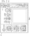
- the display devices 138 of the instrument panel 140 are configured as illuminated words. Each display device 138 may correspond to one of the landing gear assemblies 106.
- three display devices 138 include the respective messages, namely, "NOSE GEAR", “LEFT GEAR”, and “RIGHT GEAR” to indicate which of the landing gear assemblies 106 has the locking pin 128 inserted into the aperture 126.
- the display devices 138 are configured as associated landing gear lights 141 and may be positioned above the landing gear down and lock lights 143.
- the display devices 138 may light up the message or messages corresponding to the landing gear assembly 106 that still has the aperture 126 inserted into the aperture 126 in response to receiving a signal from the landing gear monitoring and alerting system 300 ( FIG. 9 ) as discussed in detail below.
- the display device 138 may include an engine-indicating and crew-alerting system (EICAS) page 148.
- EICAS engine-indicating and crew-alerting system
- the display device 138 Upon receipt of the signal from the landing gear monitoring and altering system 300, the display device 138 displays information on the EICAS page 148, indicating that the locking pin 128 of one or more landing gear assemblies 106 is in the aperture 126 of the linkage 118.
- the display device 138 may display information in the form of indicia 150, such as "NOSE PIN”, to indicate that the locking pin 128 in one of the landing gear assemblies 106 is still in the aperture 126.
- NOSE PIN the display device 138 indicates that the aperture 126 of the landing gear assembly 106 that is located in the nose 108 is inserted into the aperture 126 of the linkage 118.
- the landing gear monitoring and alerting system 300 monitors whether the locking pin 128 is disposed within the aperture 126 of at least one linkage 118.
- the locking pin 128 may extend through the linkage 118 (e.g., first linkage member 124a and second linkage member 124b) via the aperture 126 to establish a locked state of the extended landing gear assembly 106.
- This locking pin 128, which may be considered to be part of the landing gear monitoring and alerting system 300, inhibits movement of the linkage 118 when inserted into the aperture 126 to lock the landing gear assembly 106 in the extended position.
- the aperture 126 should be removed to allow the landing gear assembly 106 to move from the extended position to the retracted position. If the locking pin 128 is not removed, the landing gear monitoring and alerting system 300 alerts the aircraft operators (e.g., flight crew and ground crew) that the locking pin 128 is disposed inside the aperture 126 of the linkage 118.
- the landing gear monitoring and alerting system 300 includes a magnetic sensor 302 disposed proximate the aperture 126.
- the magnetic sensor 302 is configured to sense a magnetic response indicative of the locking pin 128 being disposed within the aperture 126 of the linkage 118 to establish the locked state of the extended landing gear assembly 106.
- the magnetic sensor 302 senses disturbances as well as changes in the magnetic field proximate the aperture 126 of the linkage 118, such as strength, direction, and flux, in order to determine whether the locking pin 128 is inside the aperture 126 of the linkage 118.
- the magnetic sensor 302 may be a Hall-effect magnetic sensor.
- testing may be conducted to sense the strength, direction, or flux of the magnetic field proximate the aperture 126 when the locking pin 128 is inserted within the aperture 126 and when the locking pin 128 is not within the aperture 126. Based on this testing, the magnetic sensor 302 determines whether the locking pin 128 is disposed within the aperture 126 of the linkage 118 in response to detecting the strength, direction, or flux of the magnetic field identified during testing when the aperture 126 is disposed within the aperture 126.
- the magnetic sensor 302 includes a magnetic sensor-activated switch 304. The magnetic sensor 302 is configured to activate the magnetic sensor-activated switch 304 upon magnetically sensing that the locking pin 128 is disposed within the aperture 126 of the linkage 118.
- the magnetic sensor 302 In response to the activation of the magnetic sensor-activated switch 304, the magnetic sensor 302 generates and provides a sensor output. The sensor output is indicative of the locking pin 128 being disposed within the aperture 126 of the linkage 118.
- the magnetic sensor 302 may further include a sensor communication module 306 configured to transmit the sensor output.
- the sensor communication module 306 of the magnetic sensor 302 may transmit the sensor output through wires or wirelessly.
- the sensor communication module 306 includes a transmitter configured to transmit wireless signals (e.g., a wireless sensor output).
- the sensor communication module 306 may be configured as a system on chip microcontroller including a built-in antenna capable of transmitting wireless signals, such as WI-FI® and BLUETOOTH® signals, to minimize the size and cost of the landing gear monitoring and alerting system 300.
- the landing gear monitoring and alerting system 300 further includes a communication module 308 in wired or wireless communication with the magnetic sensor 302.
- the communication module 308 includes a transmitter 310 coupled to the magnetic sensor 302. Consequently, the communication module 308 is configured to receive the sensor output that originates from the magnetic sensor 302. As discussed above, the sensor output is indicative of the locking pin 128 being disposed within the aperture 126 of the linkage 118.
- the communication module 308 is configured to responsively transmit a signal indicative of the locking pin 128 being disposed within the aperture 126 of the linkage 118, thereby establishing the locked state of the extended landing gear assembly 106.
- the communication module 308 is configured to transmit a signal indicative of the locking pin 128 being disposed with the aperture 126 of the linkage 118 in response to receiving the sensor output from the magnetic sensor 302, wherein the sensor output is indicative of the locking pin 128 being disposed with the aperture 126 of the linkage 118.
- the communication module 308 includes a microcontroller 312 configured to receive the sensor output from the magnetic sensor 302.
- the communication module 308 may include integrated wifi components 314 configured to wirelessly transmit the signal indicative of the locking pin 128 being disposed within the aperture 126 of the linkage 118 in order to minimize the size of the communication module 308.
- the integrated wifi components 314 may include a built-in antenna integrated on the microcontroller 312, and the microcontroller 312 may be an integrated chip.
- the microcontroller 312 may be a universal host controller interface that transmits the signal indicative of the locking pin 128 being disposed within the aperture 126 of the linkage 118 via a universal asynchronous receiver-transmitter.
- the microcontroller 312 may be a universal host controller interface to reduce or minimize the power needed to operate the microcontroller 312.
- the transmitter 310 may be a universal asynchronous receiver-transmitter to allow the magnetic sensor 302 and the communication module 308 to exchange data at their own pace.
- the communication module 308 is in communication with the flight management system (FMS) 316 of the aircraft 100. As a result, the communication module 308 is configured to receive information from the FMS 316 about the flight phase of the aircraft 100. For example, the FMS 316 may transmit flight phase information to the communication module 308 indicative of a taxiing movement of the aircraft 100. In some examples, the communication module 308 is configured to transmit the signal indicative of the locking pin 128 is disposed within the aperture 126 of the linkage 118 in response to: (a) receiving the sensor output indicative of the locking pin 128 being disposed within the aperture 126; and (b) receiving flight phase information (from the FMS 316) indicative of a taxiing movement by the aircraft 100.
- FMS flight management system
- the communication module 308 is in communication with at least one display device 138 via a data network 318.
- the data network 318 may be a wired or wireless data network.
- the display device 138 may be within the primary field of view in the cockpit 136 of the aircraft 100 and is configured to receive the signal from the communication module 308, which is indicative of the locking pin 128 being disposed within the aperture 126 of the linkage 118 to establish the locked state of the extended landing gear assembly 106.
- the display device 138 is configured to display information about the locking pin 128 being disposed within the aperture 126 to establish the locked state of the extended landing gear assembly 106.
- the information about whether the locking pin 128 is disposed with in the aperture 126 may be outputted on a synoptic page 142 of one of the display devices 138.
- the display device 138 may display information on the EICAS page 148, indicating that the locking pin 128 of one or more of landing gear assemblies 106 is disposed within the aperture 126 of the linkage 118.
- the display devices 138 may be considered to be part of the landing gear monitoring and altering system 300.
- the communication module 308 Upon receipt of the sensor output from the magnetic sensor 302 indicating that the locking pin 128 is within the aperture 126, the communication module 308 is configured to transmit the signal indicative of the locking pin 128 being disposed within the aperture 126 of the linkage 118 to a ground crew handheld device 320.
- the ground crew handheld device 320 may be, for instance, a mobile phone or any other suitable device capable of displaying information to a ground crew member that the locking pin 128 is disposed within the aperture 126 of the linkage 118.
- the ground crew may remove the locking pin 128 from the aperture 126 of the linkage 118.
- the communication module 308 may transmit the signal indicative of the locking pin 128 being disposed within the aperture 126 of the linkage 118 through an onboard networking system (ONS) 322 of the aircraft 100.
- the ONS 322 then transmits this signal to an airline operations control (AOC) server 324 via an airport wireless data network (e.g ., airport WI-FI® network) or an aircraft communications addressing and reporting system (ACARS) 326.
- AOC airline operations control
- ACARS aircraft communications addressing and reporting system
- FIG. 10 is a flowchart of a method 400 of operating the landing gear monitoring and alerting system 300.
- the method 400 begins at block 402 (i.e., the Start block). Then, the method 400 proceeds to block 404.
- the landing gear monitoring and alerting system 300 monitors a magnetic field proximate the aperture 126 of one or more landing gear assemblies 106. To do so, the microcontroller 312 reads the sensor output from the magnetic sensor 302. Next, the method 400 proceeds to block 406.
- the microcontroller 312 determines whether or not the locking pin 128 is inserted into the aperture 126 of the linkage 118 by sensing a magnetic response indicative of the locking pin 128 being disposed within the aperture 126 of the linkage 118 to establish the locked state of the landing gear assembly 106 in the extended position using the sensor output of the magnetic sensor 302.
- Sensing the magnetic response may entail activating a magnetic sensor-activated switch 304 upon magnetically sensing that the locking pin 128 is disposed within the aperture 126.
- sensing the magnetic response may entail transmitting a sensor output from the magnetic sensor-activated switch 304 to the communication module 308 of the landing gear monitoring and alerting system 300 in response to activating the magnetic sensor-activated switch 304.
- the microcontroller 312 determines that the locking pin 128 is disposed inside the aperture 126 of the linkage 118. If the locking pin 128 is not inserted into the aperture 126, then the method 400 proceeds to block 412, where the communication module 308 transmits a signal regarding the state of the locking pin 128. In this case, this signal is indicative that the locking pin 128 is not disposed within the aperture of the linkage 118 and, consequently, no alert is activated. On the other hand, if the locking pin 128 is inserted into the aperture 126 as determined at block 406, then the method 400 continues to block 408.
- the communication module 308 receives the signal from the FMS 316 indicative of the flight phase of the aircraft 100. After block 408, the method 400 proceeds to block 410.
- the microcontroller 312 determines whether the flight phase has transitioned to taxiing based on the signal received from the FMS 316. If the flight phase of the aircraft 100 has not transitioned to taxiing, the method 400 proceeds to block 412. As discussed above, at block 412, the microcontroller 312 transmits a signal that is indicative that the locking pin 128 is not disposed within the aperture of the linkage 118. After block 412, the method 400 continues to block 416. At block 416, the signal indicative that the locking pin 128 is not disposed within the aperture 126 of the linkage 118 is transmitted to the ONS 322. If the flight phase has transitioned to taxiing as determined at block 410, then the method 400 proceeds to block 414.
- the communication module 308 transmits a signal indicative of the locking pin 128 being inserted into the aperture 126 (i.e., the alert signal) in response to: (a) sensing the magnetic response indicative of the locking pin 128 being disposed within the aperture 126 of the linkage 118 to establish the locked state of the landing gear assembly in the extended position; and (b) receiving flight phase information indicative of a taxiing movement by the aircraft 100.
- the method 400 continues to block 416.
- the communication module 308 transmits the signal indicative of the locking pin 128 being inserted into the aperture 126 to the ONS 322 of the aircraft 100.
- the signal indicative that the locking pin 128 is not inserted within the aperture 126 is transmitted to the ONS 322.
- the signal indicating that the locking pin 128 is not inserted within the aperture 126 may be transmitted to the ONS 322 once the locking pin 128 is removed from the aperture 126 and the locking pin 128 is securely stored in a safety locking pin case. These signals may be transmitted wirelessly.
- the method 400 proceeds to block 418.
- the signal indicative of the locking pin 128 being inserted into the aperture 126 i.e., the alert signal
- the signal indicative of the locking pin 128 being inserted into the aperture 126 i.e., the alert signal
- the signal indicative of the locking pin 128 being inserted into the aperture 126 is transmitted in response to sensing the magnetic response indicative of the locking pin 128 being disposed within the aperture 126 to establish the locked state of the landing gear assembly 106 in the extended position
- the method 400 then proceeds to blocks 420, 422, and 424.
- the method 400 entails displaying information about the locking pin 128 being disposed within the aperture 126 on the display device 138 of the aircraft 100 in response to the transmitted signal being received by the display device via the data network 318 of the aircraft 100.
- the display device 138 has a primary field of view in the cockpit 136 of the aircraft 100.
- display information about the locking pin 128 being disposed within the aperture 126 entails illuminating associated landing gear lights 141 as shown in FIG. 7 . These lights may be located above the lands gear down and lock lights 143.
- a flash alert may be displayed on the display device 138.
- the image 144 of the relevant landing gear assembly 106 may change colors (e.g., from black to red) to indicate which of the landing gear assemblies 106 has the locking pin 128 disposed within the aperture 126 as shown in FIG. 6 .
- the display device 138 may display a message 146, indicating that the locking pin 128 is disposed in the aperture 126 in one or more of the landing gear assemblies 106 as also shown in FIG. 6 .
- a flash alert may be displayed on the synoptic page 142 or other suitable page on the display device 138, indicating which of the landing gear assemblies 106 is in the locked state. For example, as shown in FIG.
- the EICAS page 148 of the display device 138 display a message in red in the form of indicia 150.
- the indicia 150 indicates which of the landing gear assemblies 106 is in the locked state because the locking pin 128 is disposed within the aperture 126 of the linkage 118.
- a system, apparatus, structure, article, element, component, or hardware “configured to” perform a specified function is indeed capable of performing the specified function without any alteration, rather than merely having potential to perform the specified function after further modification.
- the system, apparatus, structure, article, element, component, or hardware “configured to” perform a specified function is specifically selected, created, implemented, utilized, programmed, and/or designed for the purpose of performing the specified function.
- "configured to” denotes existing characteristics of a system, apparatus, structure, article, element, component, or hardware that enable the system, apparatus, structure, article, element, component, or hardware to perform the specified function without further modification.
- a system, apparatus, structure, article, element, component, or hardware described as being “configured to” perform a particular function may additionally or alternatively be described as being “adapted to” and/or as being “operative to” perform that function.
Landscapes
- Engineering & Computer Science (AREA)
- Aviation & Aerospace Engineering (AREA)
- Mechanical Engineering (AREA)
- Traffic Control Systems (AREA)
- Alarm Systems (AREA)
Abstract
Description
- The present disclosure generally relates to aircraft, and more particularly, to an aircraft landing gear monitoring and alerting system and method.
- Some aircraft include a landing gear. During landing, the landing gear of an aircraft comes in contact with a surface of an airport runway to facilitate a smooth landing. In addition, the landing gear is used during taxiing to facilitate movement of the aircraft on the airport runway.
- The present disclosure describes an aircraft landing gear monitoring and alerting system and method. The landing gear monitoring and alerting system alerts the flight crew and ground crew when a locking pin is disposed within an aperture of a linkage of an extended landing gear assembly. This locking pin inhibits movement of the linkage, thereby precluding the landing gear assembly from moving from the extended position to a retracted position. It is desirable to remove the locking pin from the aperture of the linkage before aircraft take-off to allow the landing gear assembly to retract. Failure to do so may increase the drag acting on the aircraft, thereby increasing the fuel consumed by the aircraft. As a consequence, the aircraft may have to divert from its flight plan in order to return to the airport to allow the ground crew to remove the locking pin from the aperture of the linkage. This flight diversion may result in a financial cost to the air carrier in the form of airport parking fees, additional fuel costs, and unexpected departure slot wait times, among others. It is therefore desirable to develop a system and a method for alerting the ground crew and the flight crew of an aircraft when the locking pin is disposed inside the aperture of the linkage of the landing gear assembly.
- The presently disclosed aircraft landing gear monitoring and alerting system detects when the locking pin is disposed inside the aperture extending through the linkage of a landing gear assembly in an extended position. Upon detection of the locking pin inside the aperture, the presently disclosed aircraft gear monitoring and alerting system alerts the flight crew and the ground crew that the locking pin is disposed within the aperture extending through the linkage of the landing gear assembly, allowing the ground crew to remove the locking pin from the aperture before aircraft take-off.
- In some examples of the present disclosure, the landing gear monitoring and alerting system includes a locking pin configured to be inserted into an aperture extending through at least one linkage of an extended landing gear assembly. When inserted into the aperture, the locking pin inhibits movement of the linkage to establish a locked state of the extended landing gear assembly. The aircraft landing gear monitoring and alerting system further includes a magnetic sensor disposed proximate the aperture and configured to sense a magnetic response indicative of the locking pin being disposed within the aperture to establish the locked state of the extended landing gear assembly. The magnetic sensor is configured to generate a sensor output indicative of the locking pin being disposed within the aperture. Additionally, the aircraft landing gear monitoring and alerting system includes a communication module having a transmitter. The transmitter is coupled to the magnetic sensor so as to receive the sensor output indicative of the locking pin being disposed within the aperture of the linkage. The communication module is configured to responsively transmit a signal indicative of the locking pin being disposed within the aperture, establishing the locked state of the extended landing gear assembly.
- In some examples of the present disclosure, the landing gear monitoring and alerting system may include a display device within a primary field of view in a cockpit of an aircraft. The display device is configured to display information about the locking pin being disposed within the aperture to establish the locked state of the extended landing gear assembly in response to the transmitted signal being received by the display device via a data network of the aircraft.
- In examples of the present disclosure, the magnetic sensor may include a magnetic sensor-activated switch, wherein the magnetic sensor is configured to activate the magnetic sensor-activated switch upon magnetically sensing that the locking pin is disposed within the aperture. The magnetic sensor-activated switch also provides the sensor output to the communication module.
- In examples of the present disclosure, the linkage may include a pair of pivotally coupled linkage members. The aperture of the linkage extends through the pair of pivotally coupled linkage members. The locking pin is configured to be inserted within the aperture extending through the pair of pivotally coupled linkage members to inhibit movement of the pair of pivotally coupled linkage members relative to each other, such that the pair of pivotally coupled linkage members are held in fixed relation to each other.
- In some examples of the present disclosure, the communication module may include a microcontroller configured to receive the sensor output from the magnetic sensor. The communication module may include integrated wifi components configured to wirelessly transmit the signal indicative of the locking pin being disposed within the aperture of the linkage.
- In examples of the present disclosure, the microcontroller may be a universal host controller interface that transmits the signal indicative of the locking pin being disposed within the aperture via a universal asynchronous receiver-transmitter.
- In some examples of the present disclosure, the communication module may be configured to transmit the signal indicative of the locking pin being disposed within the aperture of the linkage to a ground crew handheld device in response to receiving the sensor output indicative of the locking pin being disposed within the aperture.
- In some examples of the present disclosure, the communication module may be configured to transmit the signal indicative of the locking pin being disposed within the aperture in response to: (a) receiving the sensor output indicative of the locking pin being disposed within the aperture; and (b) receiving flight phase information indicative of a taxiing movement by an aircraft.
- In examples of the present disclosure, the landing gear monitoring and alerting system may further include a display device within a primary field of view in a cockpit of an aircraft. The display device is configured to display information about the locking pin being disposed within the aperture of the linkage to establish the locked state of the extended landing gear assembly on a synoptic page, in response to the transmitted signal being received by the display device via a data network of the aircraft. A synoptic page may include a status display or summary display of information about the status of the aircraft, for example.
- The present disclosure also describes a method of operating a landing gear monitoring and alerting system. In some examples of the present disclosure, the method includes monitoring a magnetic field proximate an aperture of a landing gear assembly. The landing gear assembly includes at least one linkage. The aperture extends through the linkage. The landing gear assembly includes a locking pin configured to be inserted into the aperture when the landing gear assembly is in an extended position to inhibit movement of the linkage and to establish a locked state of the landing gear assembly in the extended position. The method further includes sensing a magnetic response indicative of the locking pin being disposed within the aperture to establish the locked state of the landing gear assembly in the extended position. In addition, the method includes transmitting a signal indicative of the locking pin being inserted into the aperture, establishing the locked state of the landing gear assembly in response to sensing the magnetic response indicative of the locking pin being disposed within the aperture to establish the locked state of the landing gear assembly in the extended position.
- In some examples of the present disclosure, the method may further include displaying information about the locking pin being disposed within the aperture on a display device of an aircraft in response to the transmitted signal being received by the display device via a data network of the aircraft. The display device has a primary field of view in a cockpit of the aircraft.
- In the presently disclosed method, sensing the magnetic response may include activating a magnetic sensor-activated switch upon magnetically sensing that the locking pin is disposed within the aperture and transmitting a sensor output from the magnetic sensor-activated switch to a communication module of the landing gear monitoring and alerting system in response to activating the magnetic sensor-activated switch.
- In the presently disclosed method, transmitting the signal indicative of the locking pin being inserted into the aperture may include wirelessly transmitting the signal indicative of the locking pin being inserted into the aperture.
- In the presently disclosed method, transmitting the signal indicative of the locking pin being inserted into the aperture may include transmitting the signal indicative of the locking pin being inserted into the aperture with a universal asynchronous receiver-transmitter.
- In the presently disclosed method, transmitting the signal indicative of the locking pin being inserted into the aperture may include transmitting the signal indicative of the locking pin being disposed within the aperture to a ground crew handheld device in response to sensing the magnetic response indicative of the locking pin being disposed within the aperture to establish the locked state of the landing gear assembly in the extended position.
- In the presently disclosed method, transmitting the signal indicative of the locking pin being inserted into the aperture may include transmitting the signal indicative of the locking pin being disposed within the aperture in response to sensing the magnetic response indicative of the locking pin being disposed within the aperture to establish the locked state of the landing gear assembly in the extended position and receiving flight phase information indicative of a taxiing movement by an aircraft.
- The presently disclosed method may further include displaying information about the locking pin being disposed within the aperture on a synoptic page displayed by a display device in response to the transmitted signal being received by the display device via a data network of an aircraft.
- The present disclosure also describes an aircraft including a fuselage and a landing gear assembly movable relative to the fuselage. The landing gear assembly has an extended position and includes at least one linkage and an aperture extending through the linkage. The landing gear assembly also includes a locking pin configured to be inserted into the aperture extending through the linkage. When inserted into the aperture, the locking pin inhibits movement of the linkage to establish a locked state of the landing gear assembly in the extended position. The aircraft further includes a landing gear monitoring and alerting system coupled to the landing gear assembly. The landing gear monitoring and alerting system includes a magnetic sensor disposed proximate the aperture and configured to sense a magnetic response indicative of the locking pin being disposed within the aperture to establish the locked state of the landing gear assembly in the extended position. The magnetic sensor is configured to generate a sensor output indicative of the locking pin being disposed within the aperture. The landing gear monitoring and alerting system further includes a communication module having a transmitter. The transmitter is coupled to the magnetic sensor so as to receive the sensor output indicative of the locking pin being disposed within the aperture. The communication module is configured to responsively transmit a signal indicative of the locking pin being disposed within the aperture, establishing the locked state of the landing gear assembly in the extended position.
- In some examples of the present disclosure, the aircraft may further include a cockpit and a display device disposed in the cockpit. The display device is within a primary field of view in the cockpit. Also, the display device is configured to display information about the locking pin being disposed within the aperture to establish the locked state of the landing gear assembly in the extended position, in response to the transmitted signal being received by the display device via a data network of the aircraft.
- In some examples of the present disclosure, the magnetic sensor of the aircraft may include a magnetic sensor-activated switch, wherein the magnetic sensor is configured to activate the magnetic-sensor activated switch upon magnetically sensing that the locking pin is disposed within the aperture. The magnetic-sensor activated switch is also configured to provide the sensor output to the communication module.
- The above features and advantages and other features and advantages of the present teachings are readily apparent from the following detailed description of the modes for carrying out the present teachings when taken in connection with the accompanying drawings.
- The accompanying drawings, which are incorporated into and constitute a part of this specification, illustrate implementations of the disclosure and together with the description, serve to explain the principles of the disclosure.
-
FIG. 1 is a schematic, perspective view of an aircraft including a landing gear assembly and a landing gear monitoring and alerting system. -
FIG. 2 is a schematic, perspective view of a landing gear assembly of the aircraft shown inFIG. 1 . -
FIG. 3 is a schematic, side view of a portion of the landing gear assembly shown inFIG. 2 . -
FIG. 4 is a schematic, exploded perspective view of a linkage of the landing gear assembly shown inFIG. 3 , depicting a locking pin spaced apart from an aperture extending through the linkage. -
FIG. 5 is a schematic, perspective view of a cockpit of the aircraft shown inFIG. 1 . -
FIG. 6 is a schematic, front view of a display device of the aircraft shown inFIG. 1 , depicting animage 144 of the aircraft with the landing gear assemblies. -
FIG. 7 is a schematic, front view of an instrument panel of the aircraft shown inFIG. 1 , including landing gear lights. -
FIG. 8 is a schematic, front view of a display device of the aircraft shown inFIG. 1 , including an engine-indicating and crew-alerting system (EICAS) page. -
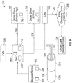
FIG. 9 is a schematic block diagram of a landing gear monitoring and altering system of the aircraft shown inFIG. 1 . -
FIG. 10 is a flowchart of a method of operating the landing gear monitoring and alerting system shown inFIG. 9 . - The foregoing summary, as well as the following detailed description of certain examples will be better understood when read in conjunction with the appended drawings. As used herein, an element or step recited in the singular and preceded by the word "a" or "an" should be understood as not necessarily excluding the plural of the elements or steps. Further, references to "one example" are not intended to be interpreted as excluding the existence of additional examples that also incorporate the recited features. Moreover, unless explicitly stated to the contrary, examples "comprising" or "having" an element or a plurality of elements having a particular property may include additional elements not having that property.
- With reference to
FIG. 1 , anaircraft 100 includes afuselage 102 and two ormore wings 104 coupled to thefuselage 102. In addition to thewings 104, theaircraft 100 includes one or morelanding gear assemblies 106 indirectly or directly coupled to thefuselage 102. As a non-limiting example, theaircraft 100 may include twolanding gear assemblies 106 each coupled under arespective wing 104 and onelanding gear assembly 106 coupled to anose 108 of thefuselage 102. Irrespective of the quantity, eachlanding gear assembly 106 is movable relative to thefuselage 102 between a retracted position and an extended position (as shown inFIG. 1 ). During landing and take-off, eachlanding gear assembly 106 is in the extended position to facilitate movement of theaircraft 100 on the ground. When theaircraft 100 is on the air, thelanding gear assemblies 106 are in the retracted position to minimize drag. - With reference to
FIGS. 2-4 , each of thelanding gear assemblies 106 includes ashock strut 110, one ormore tires 112, and a shock absorber 113 coupled between theshock strut 110 and thetires 112. The shock absorber 113 is movable relative to theshock strut 110 to dampen movement on thelanding gear assembly 106. In addition to the shock absorber 113, thelanding gear assembly 106 may include one ormore trunnions 114 coupled to theshock strut 110 to allow thelanding gear assembly 106 to rotate relative to the fuselage 102 (FIG. 1 ). Thelanding gear assembly 106 further includestorque links 116 pivotally coupled to each other. The torque links 116 are connected to theshock strut 110 and the shock absorber 113 and allow linear movement of the shock absorber 113 relative to theshock strut 110 while preventing relative rotation of the shock absorber 113 and theshock strut 110. - The
landing gear assembly 106 further includes at least onelinkage 118 pivotally coupled to theshock strut 110. Thelinkage 118 facilitates movement of thelanding gear assembly 106 relative to thefuselage 102 between the retracted position and the extended position. To move thelinkage 118, thelanding gear assembly 106 includes anactuator 120. In the depicted example, theactuator 120 is a hydraulic actuator. It is envisioned, however, theactuator 120 may be another kind of actuation system capable of moving thelinkage 118. Theactuator 120 may include anactuating cylinder 122 andhydraulic tubing 125 in fluid communication with theactuating cylinder 122. Theactuating cylinder 122 connected to thelinkage 118. Upon actuation, theactuator 120 moves thelinkage 118 to move thelanding gear assembly 106 between the retracted position and the extended position. - The
linkage 118 includes a pair of pivotally coupledlinkage members 124. In the depicted example, thelinkage 118 includes afirst linkage member 124a and asecond linkage member 124b pivotally coupled to each other. Thefirst linkage member 124a may be referred to as a lower drag brace, and thesecond linkage member 124b may be referred to as an upper drag brace. Thelanding gear assembly 106 has anaperture 126 extending through at least onelinkage 118 when thelanding gear assembly 106 is in the extended position. In particular, theaperture 126 extends through the pair of pivotally coupledlinkage members 124. In the depicted example, theaperture 126 extends through thefirst linkage member 124a and thesecond linkage member 124b. Thelanding gear assembly 106 includes alocking pin 128 configured, sized, and shaped to be inserted within theaperture 126 extending through thelinkage 118. When inserted into theaperture 126, the lockingpin 128 inhibits movement of the pair of pivotally coupledlinkage members 124 to establish a locked state of thelanding gear assembly 106 in the extended position. Specifically, when thelocking pin 128 is inserted into theaperture 126, the pair of pivotally coupledlinkage members 124 are held in a fixed relation to each other, thereby establishing the locked state of thelanding gear assembly 106 in the extended position. In other words, when thelocking pin 128 is inserted into theaperture 126, thefirst linkage member 124a and thesecond linkage member 124b are locked relative to each other, preventing thelanding gear assembly 106 from moving from the extended position to the retracted position. As a result, thelanding gear assembly 106 is locked in the extended position. Thelanding gear assembly 106 may further include aflag 130 attached to thelocking pin 128 to remind the ground crew that thelocking pin 128 should be removed from theaperture 126 before theaircraft 100 starts taxiing. - The
landing gear assembly 106 may further include alocking hook 132 and a lockingactuating rod 134 coupled to thelocking hook 132 to lock thelocking pin 128 in theaperture 126. Upon actuation by theactuator 120, for example, the lockingactuating rod 134 drives thelocking hook 132 toward thelocking pin 128 to lock thelocking pin 128 within theaperture 126. - With reference to
FIG. 5 , theaircraft 100 further includes acockpit 136 inside thenose 108 of thefuselage 102. Thecockpit 136 includes one ormore display devices 138 to visually provide information to the flight crew of theaircraft 100. Thedisplay devices 138 may be part of aninstrument panel 140 of theaircraft 100, which may include analog gauges. As a non-limiting example, thedisplay devices 138 may be liquid-crystal display (LCD) screens. Regardless of the kind ofdisplay device 138 employed, each of thedisplay devices 138 is within a primary field of view in thecockpit 136 of theaircraft 100, thereby allowing the flight crew to view the information outputted by thedisplay device 138. At least one of thedisplay devices 138 is configured to display information about whether thelocking pin 128 is disposed within theaperture 126 to establish the locked state of the extendedlanding gear assembly 106 in response to receiving a signal transmitted by a landing gear monitoring and alerting system 300 (FIG. 9 ) as discussed in detail below. The information about whether or not thelocking pin 128 is disposed with in theaperture 126 may be outputted on asynoptic page 142 of one of thedisplay devices 138 upon receipt of the signal transmitted by the landing gear monitoring and alteringsystem 300. As non-limiting examples, thedisplay devices 138 may be configured as a multi-function display (MFD), an electronic flight bag (EFB), or illuminated symbols or words on theinstrument panel 140. - With reference
FIG. 6 , thedisplay device 138, such as an MFD or an EFB, may display animage 144 of theaircraft 100 with thelanding gear assemblies 106. In response to receiving a signal from the landing gear monitoring and alteringsystem 300, thedisplay device 138 may, for example, change the color (e.g., from black to red) of theimage 144 of thelanding gear assemblies 106 that has thelocking pin 128 disposed within theaperture 126 of thelinkage 118. In addition, thedisplay device 138 may display amessage 146, indicating that thelocking pin 128 is disposed in theaperture 126 in one or more of thelanding gear assemblies 106. For example, in the depicted example, themessage 146 shown in thedisplay device 138 states "NOSE-WHEEL PIN ENGAGED" to indicate that thelocking pin 128 of thelanding gear assembly 106 that is located in thenose 108 is disposed in theaperture 126 of thatlanding gear assembly 106. - With reference to
FIG. 7 , thedisplay devices 138 of theinstrument panel 140 are configured as illuminated words. Eachdisplay device 138 may correspond to one of thelanding gear assemblies 106. For example, in the depicted example, threedisplay devices 138 include the respective messages, namely, "NOSE GEAR", "LEFT GEAR", and "RIGHT GEAR" to indicate which of thelanding gear assemblies 106 has thelocking pin 128 inserted into theaperture 126. In this example, thedisplay devices 138 are configured as associatedlanding gear lights 141 and may be positioned above the landing gear down and locklights 143. Thedisplay devices 138 may light up the message or messages corresponding to thelanding gear assembly 106 that still has theaperture 126 inserted into theaperture 126 in response to receiving a signal from the landing gear monitoring and alerting system 300 (FIG. 9 ) as discussed in detail below. - With reference to
FIG. 8 , thedisplay device 138 may include an engine-indicating and crew-alerting system (EICAS)page 148. Upon receipt of the signal from the landing gear monitoring and alteringsystem 300, thedisplay device 138 displays information on theEICAS page 148, indicating that thelocking pin 128 of one or morelanding gear assemblies 106 is in theaperture 126 of thelinkage 118. For example, thedisplay device 138 may display information in the form ofindicia 150, such as "NOSE PIN", to indicate that thelocking pin 128 in one of thelanding gear assemblies 106 is still in theaperture 126. By displaying theindicia 150, "NOSE PIN", thedisplay device 138 indicates that theaperture 126 of thelanding gear assembly 106 that is located in thenose 108 is inserted into theaperture 126 of thelinkage 118. - With reference to
FIG. 9 , the landing gear monitoring and alertingsystem 300 monitors whether thelocking pin 128 is disposed within theaperture 126 of at least onelinkage 118. As discussed above, the lockingpin 128 may extend through the linkage 118 (e.g.,first linkage member 124a andsecond linkage member 124b) via theaperture 126 to establish a locked state of the extendedlanding gear assembly 106. Thislocking pin 128, which may be considered to be part of the landing gear monitoring and alertingsystem 300, inhibits movement of thelinkage 118 when inserted into theaperture 126 to lock thelanding gear assembly 106 in the extended position. Before theaircraft 100 takes off, theaperture 126 should be removed to allow thelanding gear assembly 106 to move from the extended position to the retracted position. If thelocking pin 128 is not removed, the landing gear monitoring and alertingsystem 300 alerts the aircraft operators (e.g., flight crew and ground crew) that thelocking pin 128 is disposed inside theaperture 126 of thelinkage 118. - The landing gear monitoring and alerting
system 300 includes amagnetic sensor 302 disposed proximate theaperture 126. As such, themagnetic sensor 302 is configured to sense a magnetic response indicative of thelocking pin 128 being disposed within theaperture 126 of thelinkage 118 to establish the locked state of the extendedlanding gear assembly 106. In other words, themagnetic sensor 302 senses disturbances as well as changes in the magnetic field proximate theaperture 126 of thelinkage 118, such as strength, direction, and flux, in order to determine whether thelocking pin 128 is inside theaperture 126 of thelinkage 118. As a non-limiting example, themagnetic sensor 302 may be a Hall-effect magnetic sensor. To calibrate themagnetic sensor 302, testing may be conducted to sense the strength, direction, or flux of the magnetic field proximate theaperture 126 when thelocking pin 128 is inserted within theaperture 126 and when thelocking pin 128 is not within theaperture 126. Based on this testing, themagnetic sensor 302 determines whether thelocking pin 128 is disposed within theaperture 126 of thelinkage 118 in response to detecting the strength, direction, or flux of the magnetic field identified during testing when theaperture 126 is disposed within theaperture 126. In certain examples, themagnetic sensor 302 includes a magnetic sensor-activatedswitch 304. Themagnetic sensor 302 is configured to activate the magnetic sensor-activatedswitch 304 upon magnetically sensing that thelocking pin 128 is disposed within theaperture 126 of thelinkage 118. In response to the activation of the magnetic sensor-activatedswitch 304, themagnetic sensor 302 generates and provides a sensor output. The sensor output is indicative of thelocking pin 128 being disposed within theaperture 126 of thelinkage 118. Themagnetic sensor 302 may further include asensor communication module 306 configured to transmit the sensor output. Thesensor communication module 306 of themagnetic sensor 302 may transmit the sensor output through wires or wirelessly. In some examples, thesensor communication module 306 includes a transmitter configured to transmit wireless signals (e.g., a wireless sensor output). As a non-limiting example, thesensor communication module 306 may be configured as a system on chip microcontroller including a built-in antenna capable of transmitting wireless signals, such as WI-FI® and BLUETOOTH® signals, to minimize the size and cost of the landing gear monitoring and alertingsystem 300. - The landing gear monitoring and alerting
system 300 further includes acommunication module 308 in wired or wireless communication with themagnetic sensor 302. Thecommunication module 308 includes atransmitter 310 coupled to themagnetic sensor 302. Consequently, thecommunication module 308 is configured to receive the sensor output that originates from themagnetic sensor 302. As discussed above, the sensor output is indicative of thelocking pin 128 being disposed within theaperture 126 of thelinkage 118. Thecommunication module 308 is configured to responsively transmit a signal indicative of thelocking pin 128 being disposed within theaperture 126 of thelinkage 118, thereby establishing the locked state of the extendedlanding gear assembly 106. In other words, due to thetransmitter 310, thecommunication module 308 is configured to transmit a signal indicative of thelocking pin 128 being disposed with theaperture 126 of thelinkage 118 in response to receiving the sensor output from themagnetic sensor 302, wherein the sensor output is indicative of thelocking pin 128 being disposed with theaperture 126 of thelinkage 118. As a non-limiting example, thecommunication module 308 includes amicrocontroller 312 configured to receive the sensor output from themagnetic sensor 302. Thecommunication module 308 may includeintegrated wifi components 314 configured to wirelessly transmit the signal indicative of thelocking pin 128 being disposed within theaperture 126 of thelinkage 118 in order to minimize the size of thecommunication module 308. For instance, theintegrated wifi components 314 may include a built-in antenna integrated on themicrocontroller 312, and themicrocontroller 312 may be an integrated chip. Themicrocontroller 312 may be a universal host controller interface that transmits the signal indicative of thelocking pin 128 being disposed within theaperture 126 of thelinkage 118 via a universal asynchronous receiver-transmitter. Themicrocontroller 312 may be a universal host controller interface to reduce or minimize the power needed to operate themicrocontroller 312. Further, thetransmitter 310 may be a universal asynchronous receiver-transmitter to allow themagnetic sensor 302 and thecommunication module 308 to exchange data at their own pace. - The
communication module 308 is in communication with the flight management system (FMS) 316 of theaircraft 100. As a result, thecommunication module 308 is configured to receive information from theFMS 316 about the flight phase of theaircraft 100. For example, theFMS 316 may transmit flight phase information to thecommunication module 308 indicative of a taxiing movement of theaircraft 100. In some examples, thecommunication module 308 is configured to transmit the signal indicative of thelocking pin 128 is disposed within theaperture 126 of thelinkage 118 in response to: (a) receiving the sensor output indicative of thelocking pin 128 being disposed within theaperture 126; and (b) receiving flight phase information (from the FMS 316) indicative of a taxiing movement by theaircraft 100. - The
communication module 308 is in communication with at least onedisplay device 138 via adata network 318. Thedata network 318 may be a wired or wireless data network. As discussed above, thedisplay device 138 may be within the primary field of view in thecockpit 136 of theaircraft 100 and is configured to receive the signal from thecommunication module 308, which is indicative of thelocking pin 128 being disposed within theaperture 126 of thelinkage 118 to establish the locked state of the extendedlanding gear assembly 106. In response to receiving this signal from thecommunication module 308, thedisplay device 138 is configured to display information about thelocking pin 128 being disposed within theaperture 126 to establish the locked state of the extendedlanding gear assembly 106. The information about whether thelocking pin 128 is disposed with in theaperture 126 may be outputted on asynoptic page 142 of one of thedisplay devices 138. Alternatively, thedisplay device 138 may display information on theEICAS page 148, indicating that thelocking pin 128 of one or more oflanding gear assemblies 106 is disposed within theaperture 126 of thelinkage 118. Regardless of the configuration of thedisplay devices 138, thedisplay devices 138 may be considered to be part of the landing gear monitoring and alteringsystem 300. - Upon receipt of the sensor output from the
magnetic sensor 302 indicating that thelocking pin 128 is within theaperture 126, thecommunication module 308 is configured to transmit the signal indicative of thelocking pin 128 being disposed within theaperture 126 of thelinkage 118 to a groundcrew handheld device 320. The groundcrew handheld device 320 may be, for instance, a mobile phone or any other suitable device capable of displaying information to a ground crew member that thelocking pin 128 is disposed within theaperture 126 of thelinkage 118. Upon receiving this information on the groundcrew handheld device 320, the ground crew may remove thelocking pin 128 from theaperture 126 of thelinkage 118. Thecommunication module 308 may transmit the signal indicative of thelocking pin 128 being disposed within theaperture 126 of thelinkage 118 through an onboard networking system (ONS) 322 of theaircraft 100. TheONS 322 then transmits this signal to an airline operations control (AOC)server 324 via an airport wireless data network (e.g., airport WI-FI® network) or an aircraft communications addressing and reporting system (ACARS) 326. TheAOC server 324 then transmits this signal to the groundcrew handheld device 320. -
FIG. 10 is a flowchart of amethod 400 of operating the landing gear monitoring and alertingsystem 300. Themethod 400 begins at block 402 (i.e., the Start block). Then, themethod 400 proceeds to block 404. Atblock 404, the landing gear monitoring and alertingsystem 300 monitors a magnetic field proximate theaperture 126 of one or morelanding gear assemblies 106. To do so, themicrocontroller 312 reads the sensor output from themagnetic sensor 302. Next, themethod 400 proceeds to block 406. - At
block 406, themicrocontroller 312 determines whether or not thelocking pin 128 is inserted into theaperture 126 of thelinkage 118 by sensing a magnetic response indicative of thelocking pin 128 being disposed within theaperture 126 of thelinkage 118 to establish the locked state of thelanding gear assembly 106 in the extended position using the sensor output of themagnetic sensor 302. Sensing the magnetic response may entail activating a magnetic sensor-activatedswitch 304 upon magnetically sensing that thelocking pin 128 is disposed within theaperture 126. In addition, sensing the magnetic response may entail transmitting a sensor output from the magnetic sensor-activatedswitch 304 to thecommunication module 308 of the landing gear monitoring and alertingsystem 300 in response to activating the magnetic sensor-activatedswitch 304. In response to receiving the sensor output indicative that thelocking pin 128 is disposed within theaperture 126 of thelinkage 118, themicrocontroller 312 determines that thelocking pin 128 is disposed inside theaperture 126 of thelinkage 118. If thelocking pin 128 is not inserted into theaperture 126, then themethod 400 proceeds to block 412, where thecommunication module 308 transmits a signal regarding the state of thelocking pin 128. In this case, this signal is indicative that thelocking pin 128 is not disposed within the aperture of thelinkage 118 and, consequently, no alert is activated. On the other hand, if thelocking pin 128 is inserted into theaperture 126 as determined atblock 406, then themethod 400 continues to block 408. - At
block 408, thecommunication module 308 receives the signal from theFMS 316 indicative of the flight phase of theaircraft 100. Afterblock 408, themethod 400 proceeds to block 410. - At
block 410, themicrocontroller 312 determines whether the flight phase has transitioned to taxiing based on the signal received from theFMS 316. If the flight phase of theaircraft 100 has not transitioned to taxiing, themethod 400 proceeds to block 412. As discussed above, atblock 412, themicrocontroller 312 transmits a signal that is indicative that thelocking pin 128 is not disposed within the aperture of thelinkage 118. Afterblock 412, themethod 400 continues to block 416. Atblock 416, the signal indicative that thelocking pin 128 is not disposed within theaperture 126 of thelinkage 118 is transmitted to theONS 322. If the flight phase has transitioned to taxiing as determined atblock 410, then themethod 400 proceeds to block 414. - At
block 414, thecommunication module 308 transmits a signal indicative of thelocking pin 128 being inserted into the aperture 126 (i.e., the alert signal) in response to: (a) sensing the magnetic response indicative of thelocking pin 128 being disposed within theaperture 126 of thelinkage 118 to establish the locked state of the landing gear assembly in the extended position; and (b) receiving flight phase information indicative of a taxiing movement by theaircraft 100. Afterblock 414, themethod 400 continues to block 416. - At
block 416, thecommunication module 308 transmits the signal indicative of thelocking pin 128 being inserted into theaperture 126 to theONS 322 of theaircraft 100. Alternatively, atblock 416, the signal indicative that thelocking pin 128 is not inserted within theaperture 126 is transmitted to theONS 322. The signal indicating that thelocking pin 128 is not inserted within theaperture 126 may be transmitted to theONS 322 once the lockingpin 128 is removed from theaperture 126 and thelocking pin 128 is securely stored in a safety locking pin case. These signals may be transmitted wirelessly. Afterblock 416, themethod 400 proceeds to block 418. - At
block 418, the signal indicative of thelocking pin 128 being inserted into the aperture 126 (i.e., the alert signal) or the signal indicating that thelocking pin 128 is not inserted within theaperture 126 is transmitted to thedisplay devices 138 and the groundcrew handheld device 320 through theAOC server 324. The signal indicative of thelocking pin 128 being inserted into the aperture 126 (i.e., the alert signal) is transmitted in response to sensing the magnetic response indicative of thelocking pin 128 being disposed within theaperture 126 to establish the locked state of thelanding gear assembly 106 in the extended position Themethod 400 then proceeds toblocks - At each of
blocks method 400 entails displaying information about thelocking pin 128 being disposed within theaperture 126 on thedisplay device 138 of theaircraft 100 in response to the transmitted signal being received by the display device via thedata network 318 of theaircraft 100. As discussed above, thedisplay device 138 has a primary field of view in thecockpit 136 of theaircraft 100. For someaircraft 100 atblock 420, display information about thelocking pin 128 being disposed within theaperture 126 entails illuminating associatedlanding gear lights 141 as shown inFIG. 7 . These lights may be located above the lands gear down and locklights 143. Foraircraft 100 with EFBs atblock 422, a flash alert may be displayed on thedisplay device 138. For example, theimage 144 of the relevantlanding gear assembly 106 may change colors (e.g., from black to red) to indicate which of thelanding gear assemblies 106 has thelocking pin 128 disposed within theaperture 126 as shown inFIG. 6 . In addition, thedisplay device 138 may display amessage 146, indicating that thelocking pin 128 is disposed in theaperture 126 in one or more of thelanding gear assemblies 106 as also shown inFIG. 6 . Foraircraft 100 with EICAS and MFD pages atblock 424, a flash alert may be displayed on thesynoptic page 142 or other suitable page on thedisplay device 138, indicating which of thelanding gear assemblies 106 is in the locked state. For example, as shown inFIG. 8 , theEICAS page 148 of thedisplay device 138 display a message in red in the form ofindicia 150. Theindicia 150 indicates which of thelanding gear assemblies 106 is in the locked state because thelocking pin 128 is disposed within theaperture 126 of thelinkage 118. - Further, the disclosure comprises examples according to the following clauses:
-
Clause 1. A landing gear monitoring and alerting system (300), comprising: a locking pin (128) configured to be inserted into an aperture (126) extending through at least one linkage (118) of an extended landing gear assembly (106), which when inserted inhibits movement of the at least one linkage (118) to establish a locked state of the extended landing gear assembly (106); a magnetic sensor (302) disposed proximate the aperture (126) and configured to sense a magnetic response indicative of the locking pin (128) being disposed within the aperture (126) to establish the locked state of the extended landing gear assembly (106), and the magnetic sensor (302) being configured to generate a sensor output indicative of the locking pin (128) being disposed within the aperture (126); and a communication module (308) having a transmitter (310) being coupled to the magnetic sensor (302) so as to receive the sensor output indicative of the locking pin (128) being disposed within the aperture (126), and the communication module (308) being configured to responsively transmit a signal indicative of the locking pin (128) being disposed within the aperture (126), establishing the locked state of the extended landing gear assembly (106). - Clause 2. The landing gear monitoring and alerting system (300) of
clause 1, further comprising a display device (138) within a primary field of view in a cockpit (136) of an aircraft (100), the display device (138) being configured to display information about the locking pin (128) being disposed within the aperture (126) to establish the locked state of the extended landing gear assembly (106), in response to the transmitted signal being received by the display device (138) via a data network (318) of the aircraft (100). - Clause 3. The landing gear monitoring and alerting system (300) of
clause 1 or 2, wherein the magnetic sensor (302) comprises a magnetic sensor-activated switch (304), wherein the magnetic sensor (302) is configured to activate the magnetic sensor-activated switch (304) upon magnetically sensing that the locking pin (128) is disposed within the aperture (126), and provide the sensor output to the communication module (308). - Clause 4. The landing gear monitoring and alerting system (300) of any of
clauses 1 to 3, wherein the at least one linkage (118) includes a pair of pivotally coupled linkage members (124), the aperture (126) extends through the pair of pivotally coupled linkage members (124), and the locking pin (128) is configured to be inserted within the aperture (126) extending through the pair of pivotally coupled linkage members (124) to inhibit movement of the pair of pivotally coupled linkage members (124) relative to each other such that the pair of pivotally coupled linkage members (124) are held in fixed relation to each other. -
Clause 5. The landing gear monitoring and alerting system (300) of any ofclauses 1 to 4, wherein the communication module (308) comprises a microcontroller (312) configured to receive the sensor output from the magnetic sensor (302), and the communication module (308) includes integrated wifi components (314) configured to wirelessly transmit the signal indicative of the locking pin (128) being disposed within the aperture (126). - Clause 6. The landing gear monitoring and alerting system (300) of
clause 5, wherein the microcontroller (312) is a universal host controller interface that transmits the signal indicative of the locking pin (128) being disposed within the aperture (126) via a universal asynchronous receiver-transmitter. - Clause 7. The landing gear monitoring and alerting system (300) of any of
clauses 1 to 6, wherein the communication module (308) is configured to transmit the signal indicative of the locking pin (128) being disposed within the aperture (126) to a ground crew handheld device (320) in response to receiving the sensor output indicative of the locking pin (128) being disposed within the aperture (126). - Clause 8. The landing gear monitoring and alerting system (300) of any of
clauses 1 to 7, wherein the communication module (308) is configured to transmit the signal indicative of the locking pin (128) being disposed within the aperture (126) in response to receiving the sensor output indicative of the locking pin (128) being disposed within the aperture (126) and receiving flight phase information indicative of a taxiing movement by an aircraft (100). - Clause 9. The landing gear monitoring and alerting system (300) of any of
clauses 1 to 8, further comprising a display device (138) within a primary field of view in a cockpit (136) of an aircraft (100), the display device (138) being configured to display information about the locking pin (128) being disposed within the aperture (126) to establish the locked state of the extended landing gear assembly (106) on a synoptic page (142), in response to the transmitted signal being received by the display device (138) via a data network (318) of the aircraft (100). -
Clause 10. A method (400) of operating a landing gear monitoring and alerting system (300), comprising: monitoring a magnetic field proximate an aperture (126) of a landing gear assembly (106), the landing gear assembly (106) including at least one linkage (118), the aperture (126) extending through the at least one linkage (118), the landing gear assembly (106) including a locking pin (128) configured to be inserted into the aperture (126) when the landing gear assembly (106) is in an extended position to inhibit movement of the at least one linkage (118) and a establish a locked state of the landing gear assembly (106) in the extended position; sensing a magnetic response indicative of the locking pin (128) being disposed within the aperture (126) to establish the locked state of the landing gear assembly (106) in the extended position; and transmitting a signal indicative of the locking pin (128) being inserted into the aperture (126), establishing the locked state of the landing gear assembly (106) in response to sensing the magnetic response indicative of the locking pin (128) being disposed within the aperture (126) to establish the locked state of the landing gear assembly (106) in the extended position. - Clause 11. The method (400) of
clause 10, further comprising displaying information about the locking pin (128) being disposed within the aperture (126) on a display device (138) of an aircraft (100) in response to the transmitted signal being received by the display device (138) via a data network (318) of the aircraft (100), and the display device (138) having a primary field of view in a cockpit (136) of the aircraft (100). -
Clause 12. The method (400) ofclause 10 or 11, wherein sensing the magnetic response includes activating a magnetic sensor-activated switch (304) upon magnetically sensing that the locking pin (128) is disposed within the aperture (126) and transmitting a sensor output from the magnetic sensor-activated switch (304) to a communication module (308) of the landing gear monitoring and alerting system (300) in response to activating the magnetic sensor-activated switch (304). - Clause 13. The method (400) of any of
clauses 10 to 12, wherein transmitting the signal indicative of the locking pin (128) being inserted into the aperture (126) includes wirelessly transmitting the signal indicative of the locking pin (128) being inserted into the aperture (126). - Clause 14. The method (400) of any of
clauses 10 to 13, wherein transmitting the signal indicative of the locking pin (128) being inserted into the aperture (126) includes transmitting the signal indicative of the locking pin (128) being inserted into the aperture (126) with a universal asynchronous receiver-transmitter. - Clause 15. The method (400) of any of
clauses 10 to 14, wherein transmitting the signal indicative of the locking pin (128) being inserted into the aperture (126) includes transmitting the signal indicative of the locking pin (128) being disposed within the aperture (126) to a ground crew handheld device (320) in response to sensing the magnetic response indicative of the locking pin (128) being disposed within the aperture (126) to establish the locked state of the landing gear assembly (106) in the extended position. - Clause 16. The method (400) of any of
clauses 10 to 15, wherein transmitting the signal indicative of the locking pin (128) being inserted into the aperture (126) includes transmitting the signal indicative of the locking pin (128) being disposed within the aperture (126) in response to sensing the magnetic response indicative of the locking pin (128) being disposed within the aperture (126) to establish the locked state of the landing gear assembly (106) in the extended position and receiving flight phase information indicative of a taxiing movement by an aircraft (100). - Clause 17. The method (400) of any of
clauses 10 to 16, further comprising displaying information about the locking pin (128) being disposed within the aperture (126) on a synoptic page (142) displayed by a display device (138) in response to the transmitted signal being received by the display device (138) via a data network (318) of an aircraft (100). -
Clause 18. An aircraft (100), comprising: a fuselage (102); a landing gear assembly (106) movable relative to the fuselage (102), the landing gear assembly (106) having an extended position, the landing gear assembly (106) including at least one linkage (118) and an aperture (126) extending through the at least one linkage (118), the landing gear assembly (106) including a locking pin (128) configured to be inserted into the aperture (126) extending through the at least one linkage (118), which when inserted inhibits movement of the at least one linkage (118) to establish a locked state of the landing gear assembly (106) in the extended position; a landing gear monitoring and alerting system (300) coupled to the landing gear assembly (106), the landing gear monitoring and alerting system (300) including: a magnetic sensor (302) disposed proximate the aperture (126) and configured to sense a magnetic response indicative of the locking pin (128) being disposed within the aperture (126) to establish the locked state of the landing gear assembly (106) in the extended position, and the magnetic sensor (302) being configured to generate a sensor output indicative of the locking pin (128) being disposed within the aperture (126); and a communication module (308) having a transmitter (310) being coupled to the magnetic sensor (302) so as to receive the sensor output indicative of the locking pin (128) being disposed within the aperture (126), and the communication module (308) being configured to responsively transmit a signal indicative of the locking pin (128) being disposed within the aperture (126), establishing the locked state of the landing gear assembly (106) in the extended position. - Clause 19. The aircraft (100) of
clause 18, further comprising a cockpit (136) and a display device (138) disposed in the cockpit (136), the display device (138) being within a primary field of view in the cockpit (136), the display device (138) being configured to display information about the locking pin (128) being disposed within the aperture (126) to establish the locked state of the landing gear assembly (106) in the extended position, in response to the transmitted signal being received by the display device (138) via a data network (318) of the aircraft (100). - Clause 20. The aircraft (100) of
clause 18 or 19, wherein the magnetic sensor (302) comprises a magnetic sensor-activated switch (304), wherein the magnetic sensor (302) is configured to activate the magnetic sensor-activated switch (304) upon magnetically sensing that the locking pin (128) is disposed within the aperture (126), and provide the sensor output to the communication module (308). - As used herein, a system, apparatus, structure, article, element, component, or hardware "configured to" perform a specified function is indeed capable of performing the specified function without any alteration, rather than merely having potential to perform the specified function after further modification. In other words, the system, apparatus, structure, article, element, component, or hardware "configured to" perform a specified function is specifically selected, created, implemented, utilized, programmed, and/or designed for the purpose of performing the specified function. As used herein, "configured to" denotes existing characteristics of a system, apparatus, structure, article, element, component, or hardware that enable the system, apparatus, structure, article, element, component, or hardware to perform the specified function without further modification. For purposes of this disclosure, a system, apparatus, structure, article, element, component, or hardware described as being "configured to" perform a particular function may additionally or alternatively be described as being "adapted to" and/or as being "operative to" perform that function.
- The illustrations of the examples described herein are intended to provide a general understanding of the structure of the various examples. The illustrations are not intended to serve as a complete description of all of the elements and features of apparatus and systems that utilize the structures or methods described herein. Many other examples may be apparent to those of skill in the art upon reviewing the disclosure. Other examples may be utilized and derived from the disclosure, such that structural and logical substitutions and changes may be made without departing from the scope of the disclosure. For example, the operations listed in the
method 400 ofFIG. 4 may be performed in a different order than illustrated, two or more of the operations may be performed concurrently (or combined), or one or more of the operations may be omitted. To illustrate, the electrical field strength data may be generated before the electrical arc is produced, such as concurrently with applying the voltage to the corona generator. Accordingly, the disclosure and the figures are to be regarded as illustrative rather than restrictive.
Claims (15)
- A landing gear monitoring and alerting system (300), comprising:a locking pin (128) configured to be inserted into an aperture (126) extending through at least one linkage (118) of an extended landing gear assembly (106), which when inserted inhibits movement of the at least one linkage (118) to establish a locked state of the extended landing gear assembly (106);a magnetic sensor (302) disposed proximate the aperture (126) and configured to sense a magnetic response indicative of the locking pin (128) being disposed within the aperture (126) to establish the locked state of the extended landing gear assembly (106), and the magnetic sensor (302) being configured to generate a sensor output indicative of the locking pin (128) being disposed within the aperture (126); anda communication module (308) having a transmitter (310) being coupled to the magnetic sensor (302) so as to receive the sensor output indicative of the locking pin (128) being disposed within the aperture (126), and the communication module (308) being configured to responsively transmit a signal indicative of the locking pin (128) being disposed within the aperture (126), establishing the locked state of the extended landing gear assembly (106).
- The landing gear monitoring and alerting system (300) of claim 1, further comprising a display device (138) within a primary field of view in a cockpit (136) of an aircraft (100), the display device (138) being configured to display information about the locking pin (128) being disposed within the aperture (126) to establish the locked state of the extended landing gear assembly (106), in response to the transmitted signal being received by the display device (138) via a data network (318) of the aircraft (100).
- The landing gear monitoring and alerting system (300) of any of claims 1 to 2, wherein the magnetic sensor (302) comprises a magnetic sensor-activated switch (304), wherein the magnetic sensor (302) is configured to activate the magnetic sensor-activated switch (304) upon magnetically sensing that the locking pin (128) is disposed within the aperture (126), and provide the sensor output to the communication module (308).
- The landing gear monitoring and alerting system (300) of any of claims 1 to 3, wherein the at least one linkage (118) includes a pair of pivotally coupled linkage members (124), the aperture (126) extending through the pair of pivotally coupled linkage members (124), and the locking pin (128) is configured to be inserted within the aperture (126) extending through the pair of pivotally coupled linkage members (124) to inhibit movement of the pair of pivotally coupled linkage members (124) relative to each other such that the pair of pivotally coupled linkage members (124) are held in fixed relation to each other.
- The landing gear monitoring and alerting system (300) of any of claims 1 to 4, wherein the communication module (308) comprises a microcontroller (312) configured to receive the sensor output from the magnetic sensor (302), and the communication module (308) includes integrated wifi components (314) configured to wirelessly transmit the signal indicative of the locking pin (128) being disposed within the aperture (126).
- The landing gear monitoring and alerting system (300) of claim 5, wherein the microcontroller (312) is a universal host controller interface configured to transmit the signal indicative of the locking pin (128) being disposed within the aperture (126) via a universal asynchronous receiver-transmitter.
- The landing gear monitoring and alerting system (300) of any of claims 1 to 6, wherein the communication module (308) is configured to transmit the signal indicative of the locking pin (128) being disposed within the aperture (126) to a ground crew handheld device (320) in response to receiving the sensor output indicative of the locking pin (128) being disposed within the aperture (126).
- The landing gear monitoring and alerting system (300) of any of claims 1 to 7, wherein the communication module (308) is configured to transmit the signal indicative of the locking pin (128) being disposed within the aperture (126) in response to receiving the sensor output indicative of the locking pin (128) being disposed within the aperture (126) and receiving flight phase information indicative of a taxiing movement by an aircraft (100).
- The landing gear monitoring and alerting system of any of claims 1 to 8, wherein the landing gear monitoring and alerting system is included in an aircraft (100) comprising:a fuselage (102);a landing gear assembly (106) movable relative to the fuselage (102), the landing gear assembly (106) having an extended position, the landing gear assembly (106) including at least one linkage (118) and an aperture (126) extending through the at least one linkage (118), the landing gear assembly (106) including a locking pin (128) configured to be inserted into the aperture (126) extending through the at least one linkage (118), which when inserted inhibits movement of the at least one linkage (118) to establish a locked state of the landing gear assembly (106) in the extended position; anda cockpit (136) and a display device (138) disposed in the cockpit (136), the display device (138) being within a primary field of view in the cockpit (136), the display device (138) being configured to display information about the locking pin (128) being disposed within the aperture (126) to establish the locked state of the landing gear assembly (106) in the extended position, in response to the transmitted signal being received by the display device (138) via a data network (318) of the aircraft (100).
- A method (400) of operating a landing gear monitoring and alerting system (300), comprising:monitoring a magnetic field proximate an aperture (126) of a landing gear assembly (106), the landing gear assembly (106) including at least one linkage (118), the aperture (126) extending through the at least one linkage (118), the landing gear assembly (106) including a locking pin (128) configured to be inserted into the aperture (126) when the landing gear assembly (106) is in an extended position to inhibit movement of the at least one linkage (118) and to establish a locked state of the landing gear assembly (106) in the extended position;sensing a magnetic response indicative of the locking pin (128) being disposed within the aperture (126) to establish the locked state of the landing gear assembly (106) in the extended position; andtransmitting a signal indicative of the locking pin (128) being inserted into the aperture (126), establishing the locked state of the landing gear assembly (106) in response to sensing the magnetic response indicative of the locking pin (128) being disposed within the aperture (126) to establish the locked state of the landing gear assembly (106) in the extended position.
- The method (400) of claim 10, further comprising displaying information about the locking pin (128) being disposed within the aperture (126) on a display device (138) of an aircraft (100) in response to the transmitted signal being received by the display device (138) via a data network (318) of the aircraft (100), and the display device (138) having a primary field of view in a cockpit (136) of the aircraft (100).
- The method (400) of any of claims 10 to 11, wherein sensing the magnetic response includes activating a magnetic sensor-activated switch (304) upon magnetically sensing that the locking pin (128) is disposed within the aperture (126) and transmitting a sensor output from the magnetic sensor-activated switch (304) to a communication module (308) of the landing gear monitoring and alerting system (300) in response to activating the magnetic sensor-activated switch (304).
- The method (400) of any of claims 10 to 12, wherein transmitting the signal indicative of the locking pin (128) being inserted into the aperture (126) includes wirelessly transmitting the signal indicative of the locking pin (128) being inserted into the aperture (126), or transmitting the signal indicative of the locking pin (128) being inserted into the aperture (126) with a universal asynchronous receiver-transmitter.
- The method (400) of any of claims 10 to 13, wherein transmitting the signal indicative of the locking pin (128) being inserted into the aperture (126) includes transmitting the signal indicative of the locking pin (128) being disposed within the aperture (126) in response to sensing the magnetic response indicative of the locking pin (128) being disposed within the aperture (126) to establish the locked state of the landing gear assembly (106) in the extended position and receiving flight phase information indicative of a taxiing movement by an aircraft (100) .
- The method (400) of any of claims 10 to 14, further comprising displaying information about the locking pin (128) being disposed within the aperture (126) on a synoptic page (142) displayed by a display device (138) in response to the transmitted signal being received by the display device (138) via a data network (318) of an aircraft (100).
Applications Claiming Priority (1)
| Application Number | Priority Date | Filing Date | Title |
|---|---|---|---|
| US16/867,985 US11919657B2 (en) | 2020-05-06 | 2020-05-06 | Aircraft landing gear monitoring and alerting system and method |
Publications (2)
| Publication Number | Publication Date |
|---|---|
| EP3907130A1 true EP3907130A1 (en) | 2021-11-10 |
| EP3907130B1 EP3907130B1 (en) | 2023-08-09 |
Family
ID=74870628
Family Applications (1)
| Application Number | Title | Priority Date | Filing Date |
|---|---|---|---|
| EP21161608.1A Active EP3907130B1 (en) | 2020-05-06 | 2021-03-09 | Aircraft landing gear monitoring and alerting system and method |
Country Status (6)
| Country | Link |
|---|---|
| US (1) | US11919657B2 (en) |
| EP (1) | EP3907130B1 (en) |
| JP (1) | JP7674901B2 (en) |
| CN (1) | CN113619775B (en) |
| AU (1) | AU2021200942A1 (en) |
| BR (1) | BR102021002626A2 (en) |
Cited By (1)
| Publication number | Priority date | Publication date | Assignee | Title |
|---|---|---|---|---|
| CN117048820A (en) * | 2023-09-04 | 2023-11-14 | 厦门大学 | A magnetic aircraft landing gear |
Families Citing this family (1)
| Publication number | Priority date | Publication date | Assignee | Title |
|---|---|---|---|---|
| EP4410683B1 (en) * | 2023-01-31 | 2025-11-12 | Airbus SAS | Method and system for monitoring operations of landing gears of aircrafts |
Citations (4)
| Publication number | Priority date | Publication date | Assignee | Title |
|---|---|---|---|---|
| US20090242696A1 (en) * | 2006-05-17 | 2009-10-01 | Airbus | Device for locking a movable component of an aircraft |
| US8256703B1 (en) * | 2010-06-21 | 2012-09-04 | Jefferson Ernest T | Aircraft ground maintenance tether asssembly |
| US20180265215A1 (en) * | 2015-11-23 | 2018-09-20 | The Boeing Company | Methods and apparatus for determing seatbelt status |
| US20180286258A1 (en) * | 2017-03-31 | 2018-10-04 | Airprox USA, Inc. | Virtual Radar Apparatus and Method |
Family Cites Families (17)
| Publication number | Priority date | Publication date | Assignee | Title |
|---|---|---|---|---|
| US6405975B1 (en) * | 1995-12-19 | 2002-06-18 | The Boeing Company | Airplane ground maneuvering camera system |
| US5839692A (en) * | 1997-06-13 | 1998-11-24 | The Boeing Company | Splayable aircraft nose landing gear |
| KR200393583Y1 (en) * | 2005-04-28 | 2005-08-24 | 조원명 | Downlock pin warning system |
| FR2886620B1 (en) * | 2005-06-07 | 2008-12-19 | Airbus France Sas | TRAPPING OPENING AND CLOSING SYSTEM FOR LANDING TRAIN BOX OF AN AIRCRAFT |
| US7719416B2 (en) * | 2005-09-09 | 2010-05-18 | Microstrain, Inc. | Energy harvesting, wireless structural health monitoring system |
| GB0704878D0 (en) * | 2007-03-14 | 2007-04-18 | Trw Ltd | Aircraft landing gear monitoring apparatus |
| FR2917217B1 (en) * | 2007-06-07 | 2009-07-24 | Messier Bugatti Sa | LIGHTER EQUIPPED WITH A COMMUNICATION DEVICE BETWEEN A WHEEL AND THE LICENSEE |
| GB2466223A (en) * | 2008-12-15 | 2010-06-16 | Robert John Sykes | Aircraft ground lock detection device. |
| US8517301B1 (en) * | 2010-06-21 | 2013-08-27 | Serias Design LLC | Aircraft ground maintenance tether assembly |
| BRPI1003411A2 (en) * | 2010-09-17 | 2013-01-08 | Nascimento Rud Elenton Fernandes Do | aircraft landing gear safety sensor presence sensor |
| FR3007545B1 (en) * | 2013-06-21 | 2020-03-27 | Thales | SYSTEM METHOD AND COMPUTER PROGRAM FOR PROVIDING DATA RELATING TO AN OPERATION OF AN AIRCRAFT ON A MAN-MACHINE INTERFACE |
| WO2015138327A1 (en) * | 2014-03-11 | 2015-09-17 | Cessna Aircraft Company | Touch screen instrument panel |
| US20180232097A1 (en) * | 2014-03-11 | 2018-08-16 | Textron Aviation Inc. | Touch Screen Instrument Panel |
| ITUA20162712A1 (en) * | 2016-04-19 | 2017-10-19 | Magnaghi Aeronautica S P A | System Structure Trolley for Aircraft equipped with electromechanical actuation and Aircraft equipped with this Structure |
| US10941826B2 (en) * | 2018-09-12 | 2021-03-09 | Honeywell International Inc. | Determining estimated remaining use of brake assembly |
| US11498662B2 (en) * | 2019-10-09 | 2022-11-15 | Goodrich Corporation | Electrically operated landing gear lock system |
| EP3805097B1 (en) * | 2019-10-09 | 2023-04-12 | Goodrich Corporation | Electrically operated landing gear lock system |
-
2020
- 2020-05-06 US US16/867,985 patent/US11919657B2/en active Active
-
2021
- 2021-02-11 BR BR102021002626-0A patent/BR102021002626A2/en unknown
- 2021-02-12 AU AU2021200942A patent/AU2021200942A1/en active Pending
- 2021-03-09 EP EP21161608.1A patent/EP3907130B1/en active Active
- 2021-04-30 JP JP2021077035A patent/JP7674901B2/en active Active
- 2021-04-30 CN CN202110483567.9A patent/CN113619775B/en active Active
Patent Citations (4)
| Publication number | Priority date | Publication date | Assignee | Title |
|---|---|---|---|---|
| US20090242696A1 (en) * | 2006-05-17 | 2009-10-01 | Airbus | Device for locking a movable component of an aircraft |
| US8256703B1 (en) * | 2010-06-21 | 2012-09-04 | Jefferson Ernest T | Aircraft ground maintenance tether asssembly |
| US20180265215A1 (en) * | 2015-11-23 | 2018-09-20 | The Boeing Company | Methods and apparatus for determing seatbelt status |
| US20180286258A1 (en) * | 2017-03-31 | 2018-10-04 | Airprox USA, Inc. | Virtual Radar Apparatus and Method |
Cited By (1)
| Publication number | Priority date | Publication date | Assignee | Title |
|---|---|---|---|---|
| CN117048820A (en) * | 2023-09-04 | 2023-11-14 | 厦门大学 | A magnetic aircraft landing gear |
Also Published As
| Publication number | Publication date |
|---|---|
| JP2021185072A (en) | 2021-12-09 |
| US20210347498A1 (en) | 2021-11-11 |
| CN113619775A (en) | 2021-11-09 |
| BR102021002626A2 (en) | 2021-11-09 |
| JP7674901B2 (en) | 2025-05-12 |
| US11919657B2 (en) | 2024-03-05 |
| EP3907130B1 (en) | 2023-08-09 |
| AU2021200942A1 (en) | 2021-11-25 |
| CN113619775B (en) | 2025-11-21 |
Similar Documents
| Publication | Publication Date | Title |
|---|---|---|
| EP3907130A1 (en) | Aircraft landing gear monitoring and alerting system and method | |
| CN101443234B (en) | Locking device, detection system of the device and aircraft with the system | |
| EP2261878B1 (en) | Method and system for approach decision display | |
| US10301007B2 (en) | Wing fold controller | |
| CA2829281C (en) | Wing fold controller | |
| EP3812280B1 (en) | Tanker aircraft comprising a referencing system | |
| PT925568E (en) | MAN-MACHINE INTERFACE FOR THE CONTROL OF AIRPORT TRAFFIC | |
| BR112015027535B1 (en) | AIRCRAFT, VEHICLE ENVIRONMENT SENSING SYSTEM, AND, METHOD FOR PROVIDING INFORMATION REGARDING THE SURROUNDINGS OF A VEHICLE | |
| CN105644800A (en) | Take-off warning system | |
| EP2982601B1 (en) | Aircraft safety system | |
| CN108172029A (en) | The oiling mode implementation method and device of a kind of tanker aircraft airborne collision avoidance system | |
| CN113129620A (en) | Vehicle signal lamp system at intersection of aircraft taxiway and service lane based on radar | |
| US7908079B1 (en) | Portable runway intersection display and monitoring system | |
| CN103832595B (en) | Display system for airborne vehicle driving cabin | |
| EP0469094B2 (en) | An aircraft parking and information system | |
| US12131657B2 (en) | Collision avoidance system | |
| GB2466223A (en) | Aircraft ground lock detection device. | |
| CN222213539U (en) | Runway release variable indication marking device for airport | |
| JPH11120499A (en) | Navigation position indicator | |
| CN109709629A (en) | Integrated display system for flight environment of vehicle | |
| CN110517613A (en) | Remote control security warning sign | |
| Prinzel III et al. | Flight deck display technologies for 4dt and surface equivalent visual operations | |
| KR101674612B1 (en) | Instrument landing facility integrated monitoring and control system | |
| CN121306040A (en) | A rearview mirror device and method for displaying the connection status of a bridge-mounted static transformer power supply | |
| GB2585263A (en) | Heavy assisted logic |
Legal Events
| Date | Code | Title | Description |
|---|---|---|---|
| PUAI | Public reference made under article 153(3) epc to a published international application that has entered the european phase |
Free format text: ORIGINAL CODE: 0009012 |
|
| STAA | Information on the status of an ep patent application or granted ep patent |
Free format text: STATUS: THE APPLICATION HAS BEEN PUBLISHED |
|
| AK | Designated contracting states |
Kind code of ref document: A1 Designated state(s): AL AT BE BG CH CY CZ DE DK EE ES FI FR GB GR HR HU IE IS IT LI LT LU LV MC MK MT NL NO PL PT RO RS SE SI SK SM TR |
|
| B565 | Issuance of search results under rule 164(2) epc |
Effective date: 20210901 |
|
| STAA | Information on the status of an ep patent application or granted ep patent |
Free format text: STATUS: REQUEST FOR EXAMINATION WAS MADE |
|
| 17P | Request for examination filed |
Effective date: 20220419 |
|
| RBV | Designated contracting states (corrected) |
Designated state(s): AL AT BE BG CH CY CZ DE DK EE ES FI FR GB GR HR HU IE IS IT LI LT LU LV MC MK MT NL NO PL PT RO RS SE SI SK SM TR |
|
| GRAP | Despatch of communication of intention to grant a patent |
Free format text: ORIGINAL CODE: EPIDOSNIGR1 |
|
| STAA | Information on the status of an ep patent application or granted ep patent |
Free format text: STATUS: GRANT OF PATENT IS INTENDED |
|
| RAP3 | Party data changed (applicant data changed or rights of an application transferred) |
Owner name: THE BOEING COMPANY |
|
| RIC1 | Information provided on ipc code assigned before grant |
Ipc: B64D 43/00 20060101ALN20230217BHEP Ipc: B64D 45/00 20060101ALI20230217BHEP Ipc: B64C 25/28 20060101AFI20230217BHEP |
|
| INTG | Intention to grant announced |
Effective date: 20230309 |
|
| GRAS | Grant fee paid |
Free format text: ORIGINAL CODE: EPIDOSNIGR3 |
|
| GRAA | (expected) grant |
Free format text: ORIGINAL CODE: 0009210 |
|
| STAA | Information on the status of an ep patent application or granted ep patent |
Free format text: STATUS: THE PATENT HAS BEEN GRANTED |
|
| P01 | Opt-out of the competence of the unified patent court (upc) registered |
Effective date: 20230612 |
|
| AK | Designated contracting states |
Kind code of ref document: B1 Designated state(s): AL AT BE BG CH CY CZ DE DK EE ES FI FR GB GR HR HU IE IS IT LI LT LU LV MC MK MT NL NO PL PT RO RS SE SI SK SM TR |
|
| REG | Reference to a national code |
Ref country code: GB Ref legal event code: FG4D |
|
| REG | Reference to a national code |
Ref country code: CH Ref legal event code: EP |
|
| REG | Reference to a national code |
Ref country code: IE Ref legal event code: FG4D |
|
| REG | Reference to a national code |
Ref country code: DE Ref legal event code: R096 Ref document number: 602021004053 Country of ref document: DE |
|
| REG | Reference to a national code |
Ref country code: LT Ref legal event code: MG9D |
|
| REG | Reference to a national code |
Ref country code: NL Ref legal event code: MP Effective date: 20230809 |
|
| REG | Reference to a national code |
Ref country code: AT Ref legal event code: MK05 Ref document number: 1597261 Country of ref document: AT Kind code of ref document: T Effective date: 20230809 |
|
| PG25 | Lapsed in a contracting state [announced via postgrant information from national office to epo] |
Ref country code: GR Free format text: LAPSE BECAUSE OF FAILURE TO SUBMIT A TRANSLATION OF THE DESCRIPTION OR TO PAY THE FEE WITHIN THE PRESCRIBED TIME-LIMIT Effective date: 20231110 |
|
| PG25 | Lapsed in a contracting state [announced via postgrant information from national office to epo] |
Ref country code: IS Free format text: LAPSE BECAUSE OF FAILURE TO SUBMIT A TRANSLATION OF THE DESCRIPTION OR TO PAY THE FEE WITHIN THE PRESCRIBED TIME-LIMIT Effective date: 20231209 |
|
| PG25 | Lapsed in a contracting state [announced via postgrant information from national office to epo] |
Ref country code: SE Free format text: LAPSE BECAUSE OF FAILURE TO SUBMIT A TRANSLATION OF THE DESCRIPTION OR TO PAY THE FEE WITHIN THE PRESCRIBED TIME-LIMIT Effective date: 20230809 Ref country code: RS Free format text: LAPSE BECAUSE OF FAILURE TO SUBMIT A TRANSLATION OF THE DESCRIPTION OR TO PAY THE FEE WITHIN THE PRESCRIBED TIME-LIMIT Effective date: 20230809 Ref country code: PT Free format text: LAPSE BECAUSE OF FAILURE TO SUBMIT A TRANSLATION OF THE DESCRIPTION OR TO PAY THE FEE WITHIN THE PRESCRIBED TIME-LIMIT Effective date: 20231211 Ref country code: NO Free format text: LAPSE BECAUSE OF FAILURE TO SUBMIT A TRANSLATION OF THE DESCRIPTION OR TO PAY THE FEE WITHIN THE PRESCRIBED TIME-LIMIT Effective date: 20231109 Ref country code: NL Free format text: LAPSE BECAUSE OF FAILURE TO SUBMIT A TRANSLATION OF THE DESCRIPTION OR TO PAY THE FEE WITHIN THE PRESCRIBED TIME-LIMIT Effective date: 20230809 Ref country code: LV Free format text: LAPSE BECAUSE OF FAILURE TO SUBMIT A TRANSLATION OF THE DESCRIPTION OR TO PAY THE FEE WITHIN THE PRESCRIBED TIME-LIMIT Effective date: 20230809 Ref country code: LT Free format text: LAPSE BECAUSE OF FAILURE TO SUBMIT A TRANSLATION OF THE DESCRIPTION OR TO PAY THE FEE WITHIN THE PRESCRIBED TIME-LIMIT Effective date: 20230809 Ref country code: IS Free format text: LAPSE BECAUSE OF FAILURE TO SUBMIT A TRANSLATION OF THE DESCRIPTION OR TO PAY THE FEE WITHIN THE PRESCRIBED TIME-LIMIT Effective date: 20231209 Ref country code: HR Free format text: LAPSE BECAUSE OF FAILURE TO SUBMIT A TRANSLATION OF THE DESCRIPTION OR TO PAY THE FEE WITHIN THE PRESCRIBED TIME-LIMIT Effective date: 20230809 Ref country code: GR Free format text: LAPSE BECAUSE OF FAILURE TO SUBMIT A TRANSLATION OF THE DESCRIPTION OR TO PAY THE FEE WITHIN THE PRESCRIBED TIME-LIMIT Effective date: 20231110 Ref country code: FI Free format text: LAPSE BECAUSE OF FAILURE TO SUBMIT A TRANSLATION OF THE DESCRIPTION OR TO PAY THE FEE WITHIN THE PRESCRIBED TIME-LIMIT Effective date: 20230809 Ref country code: AT Free format text: LAPSE BECAUSE OF FAILURE TO SUBMIT A TRANSLATION OF THE DESCRIPTION OR TO PAY THE FEE WITHIN THE PRESCRIBED TIME-LIMIT Effective date: 20230809 |
|
| PG25 | Lapsed in a contracting state [announced via postgrant information from national office to epo] |
Ref country code: PL Free format text: LAPSE BECAUSE OF FAILURE TO SUBMIT A TRANSLATION OF THE DESCRIPTION OR TO PAY THE FEE WITHIN THE PRESCRIBED TIME-LIMIT Effective date: 20230809 |
|
| PG25 | Lapsed in a contracting state [announced via postgrant information from national office to epo] |
Ref country code: ES Free format text: LAPSE BECAUSE OF FAILURE TO SUBMIT A TRANSLATION OF THE DESCRIPTION OR TO PAY THE FEE WITHIN THE PRESCRIBED TIME-LIMIT Effective date: 20230809 |
|
| PG25 | Lapsed in a contracting state [announced via postgrant information from national office to epo] |
Ref country code: SM Free format text: LAPSE BECAUSE OF FAILURE TO SUBMIT A TRANSLATION OF THE DESCRIPTION OR TO PAY THE FEE WITHIN THE PRESCRIBED TIME-LIMIT Effective date: 20230809 Ref country code: RO Free format text: LAPSE BECAUSE OF FAILURE TO SUBMIT A TRANSLATION OF THE DESCRIPTION OR TO PAY THE FEE WITHIN THE PRESCRIBED TIME-LIMIT Effective date: 20230809 Ref country code: ES Free format text: LAPSE BECAUSE OF FAILURE TO SUBMIT A TRANSLATION OF THE DESCRIPTION OR TO PAY THE FEE WITHIN THE PRESCRIBED TIME-LIMIT Effective date: 20230809 Ref country code: EE Free format text: LAPSE BECAUSE OF FAILURE TO SUBMIT A TRANSLATION OF THE DESCRIPTION OR TO PAY THE FEE WITHIN THE PRESCRIBED TIME-LIMIT Effective date: 20230809 Ref country code: DK Free format text: LAPSE BECAUSE OF FAILURE TO SUBMIT A TRANSLATION OF THE DESCRIPTION OR TO PAY THE FEE WITHIN THE PRESCRIBED TIME-LIMIT Effective date: 20230809 Ref country code: CZ Free format text: LAPSE BECAUSE OF FAILURE TO SUBMIT A TRANSLATION OF THE DESCRIPTION OR TO PAY THE FEE WITHIN THE PRESCRIBED TIME-LIMIT Effective date: 20230809 Ref country code: SK Free format text: LAPSE BECAUSE OF FAILURE TO SUBMIT A TRANSLATION OF THE DESCRIPTION OR TO PAY THE FEE WITHIN THE PRESCRIBED TIME-LIMIT Effective date: 20230809 |
|
| REG | Reference to a national code |
Ref country code: DE Ref legal event code: R097 Ref document number: 602021004053 Country of ref document: DE |
|
| PG25 | Lapsed in a contracting state [announced via postgrant information from national office to epo] |
Ref country code: IT Free format text: LAPSE BECAUSE OF FAILURE TO SUBMIT A TRANSLATION OF THE DESCRIPTION OR TO PAY THE FEE WITHIN THE PRESCRIBED TIME-LIMIT Effective date: 20230809 |
|
| PLBE | No opposition filed within time limit |
Free format text: ORIGINAL CODE: 0009261 |
|
| STAA | Information on the status of an ep patent application or granted ep patent |
Free format text: STATUS: NO OPPOSITION FILED WITHIN TIME LIMIT |
|
| 26N | No opposition filed |
Effective date: 20240513 |
|
| PG25 | Lapsed in a contracting state [announced via postgrant information from national office to epo] |
Ref country code: SI Free format text: LAPSE BECAUSE OF FAILURE TO SUBMIT A TRANSLATION OF THE DESCRIPTION OR TO PAY THE FEE WITHIN THE PRESCRIBED TIME-LIMIT Effective date: 20230809 |
|
| REG | Reference to a national code |
Ref country code: CH Ref legal event code: PL |
|
| PG25 | Lapsed in a contracting state [announced via postgrant information from national office to epo] |
Ref country code: BG Free format text: LAPSE BECAUSE OF FAILURE TO SUBMIT A TRANSLATION OF THE DESCRIPTION OR TO PAY THE FEE WITHIN THE PRESCRIBED TIME-LIMIT Effective date: 20230809 |
|
| PG25 | Lapsed in a contracting state [announced via postgrant information from national office to epo] |
Ref country code: LU Free format text: LAPSE BECAUSE OF NON-PAYMENT OF DUE FEES Effective date: 20240309 |
|
| PG25 | Lapsed in a contracting state [announced via postgrant information from national office to epo] |
Ref country code: MC Free format text: LAPSE BECAUSE OF FAILURE TO SUBMIT A TRANSLATION OF THE DESCRIPTION OR TO PAY THE FEE WITHIN THE PRESCRIBED TIME-LIMIT Effective date: 20230809 |
|
| PG25 | Lapsed in a contracting state [announced via postgrant information from national office to epo] |
Ref country code: MC Free format text: LAPSE BECAUSE OF FAILURE TO SUBMIT A TRANSLATION OF THE DESCRIPTION OR TO PAY THE FEE WITHIN THE PRESCRIBED TIME-LIMIT Effective date: 20230809 Ref country code: LU Free format text: LAPSE BECAUSE OF NON-PAYMENT OF DUE FEES Effective date: 20240309 Ref country code: BG Free format text: LAPSE BECAUSE OF FAILURE TO SUBMIT A TRANSLATION OF THE DESCRIPTION OR TO PAY THE FEE WITHIN THE PRESCRIBED TIME-LIMIT Effective date: 20230809 |
|
| REG | Reference to a national code |
Ref country code: BE Ref legal event code: MM Effective date: 20240331 |
|
| PG25 | Lapsed in a contracting state [announced via postgrant information from national office to epo] |
Ref country code: BE Free format text: LAPSE BECAUSE OF NON-PAYMENT OF DUE FEES Effective date: 20240331 |
|
| PG25 | Lapsed in a contracting state [announced via postgrant information from national office to epo] |
Ref country code: IE Free format text: LAPSE BECAUSE OF NON-PAYMENT OF DUE FEES Effective date: 20240309 |
|
| PG25 | Lapsed in a contracting state [announced via postgrant information from national office to epo] |
Ref country code: IE Free format text: LAPSE BECAUSE OF NON-PAYMENT OF DUE FEES Effective date: 20240309 Ref country code: BE Free format text: LAPSE BECAUSE OF NON-PAYMENT OF DUE FEES Effective date: 20240331 Ref country code: CH Free format text: LAPSE BECAUSE OF NON-PAYMENT OF DUE FEES Effective date: 20240331 |
|
| PG25 | Lapsed in a contracting state [announced via postgrant information from national office to epo] |
Ref country code: CY Free format text: LAPSE BECAUSE OF FAILURE TO SUBMIT A TRANSLATION OF THE DESCRIPTION OR TO PAY THE FEE WITHIN THE PRESCRIBED TIME-LIMIT; INVALID AB INITIO Effective date: 20210309 |
|
| PG25 | Lapsed in a contracting state [announced via postgrant information from national office to epo] |
Ref country code: HU Free format text: LAPSE BECAUSE OF FAILURE TO SUBMIT A TRANSLATION OF THE DESCRIPTION OR TO PAY THE FEE WITHIN THE PRESCRIBED TIME-LIMIT; INVALID AB INITIO Effective date: 20210309 |
|
| PG25 | Lapsed in a contracting state [announced via postgrant information from national office to epo] |
Ref country code: TR Free format text: LAPSE BECAUSE OF FAILURE TO SUBMIT A TRANSLATION OF THE DESCRIPTION OR TO PAY THE FEE WITHIN THE PRESCRIBED TIME-LIMIT Effective date: 20230809 |
|
| PGFP | Annual fee paid to national office [announced via postgrant information from national office to epo] |
Ref country code: GB Payment date: 20260327 Year of fee payment: 6 |
|
| PGFP | Annual fee paid to national office [announced via postgrant information from national office to epo] |
Ref country code: DE Payment date: 20260327 Year of fee payment: 6 |
|
| PGFP | Annual fee paid to national office [announced via postgrant information from national office to epo] |
Ref country code: FR Payment date: 20260325 Year of fee payment: 6 |