EP3907030A1 - Cutting insert - Google Patents
Cutting insert Download PDFInfo
- Publication number
- EP3907030A1 EP3907030A1 EP20858318.7A EP20858318A EP3907030A1 EP 3907030 A1 EP3907030 A1 EP 3907030A1 EP 20858318 A EP20858318 A EP 20858318A EP 3907030 A1 EP3907030 A1 EP 3907030A1
- Authority
- EP
- European Patent Office
- Prior art keywords
- edge
- end surface
- cutting
- outer peripheral
- cutting edge
- Prior art date
- Legal status (The legal status is an assumption and is not a legal conclusion. Google has not performed a legal analysis and makes no representation as to the accuracy of the status listed.)
- Granted
Links
Images




Classifications
-
- B—PERFORMING OPERATIONS; TRANSPORTING
- B23—MACHINE TOOLS; METAL-WORKING NOT OTHERWISE PROVIDED FOR
- B23C—MILLING
- B23C5/00—Milling-cutters
- B23C5/16—Milling-cutters characterised by physical features other than shape
- B23C5/20—Milling-cutters characterised by physical features other than shape with removable cutter bits or teeth or cutting inserts
-
- B—PERFORMING OPERATIONS; TRANSPORTING
- B23—MACHINE TOOLS; METAL-WORKING NOT OTHERWISE PROVIDED FOR
- B23B—TURNING; BORING
- B23B27/00—Tools for turning or boring machines; Tools of a similar kind in general; Accessories therefor
-
- B—PERFORMING OPERATIONS; TRANSPORTING
- B23—MACHINE TOOLS; METAL-WORKING NOT OTHERWISE PROVIDED FOR
- B23B—TURNING; BORING
- B23B27/00—Tools for turning or boring machines; Tools of a similar kind in general; Accessories therefor
- B23B27/14—Cutting tools of which the bits or tips or cutting inserts are of special material
- B23B27/16—Cutting tools of which the bits or tips or cutting inserts are of special material with exchangeable cutting bits or cutting inserts, e.g. able to be clamped
- B23B27/1677—Cutting tools of which the bits or tips or cutting inserts are of special material with exchangeable cutting bits or cutting inserts, e.g. able to be clamped with plate-like cutting inserts clamped by a clamping member acting almost perpendicularly on the chip-forming plane and at the same time upon the wall of a hole in the insert
-
- B—PERFORMING OPERATIONS; TRANSPORTING
- B23—MACHINE TOOLS; METAL-WORKING NOT OTHERWISE PROVIDED FOR
- B23C—MILLING
- B23C5/00—Milling-cutters
- B23C5/16—Milling-cutters characterised by physical features other than shape
- B23C5/20—Milling-cutters characterised by physical features other than shape with removable cutter bits or teeth or cutting inserts
- B23C5/202—Plate-like cutting inserts with special form
-
- B—PERFORMING OPERATIONS; TRANSPORTING
- B23—MACHINE TOOLS; METAL-WORKING NOT OTHERWISE PROVIDED FOR
- B23B—TURNING; BORING
- B23B2205/00—Fixation of cutting inserts in holders
- B23B2205/04—Fixation screws, bolts or pins of particular form
-
- B—PERFORMING OPERATIONS; TRANSPORTING
- B23—MACHINE TOOLS; METAL-WORKING NOT OTHERWISE PROVIDED FOR
- B23B—TURNING; BORING
- B23B2205/00—Fixation of cutting inserts in holders
- B23B2205/12—Seats for cutting inserts
-
- B—PERFORMING OPERATIONS; TRANSPORTING
- B23—MACHINE TOOLS; METAL-WORKING NOT OTHERWISE PROVIDED FOR
- B23B—TURNING; BORING
- B23B2210/00—Details of turning tools
- B23B2210/02—Tool holders having multiple cutting inserts
-
- B—PERFORMING OPERATIONS; TRANSPORTING
- B23—MACHINE TOOLS; METAL-WORKING NOT OTHERWISE PROVIDED FOR
- B23C—MILLING
- B23C2200/00—Details of milling cutting inserts
- B23C2200/04—Overall shape
- B23C2200/0494—Rectangular
-
- B—PERFORMING OPERATIONS; TRANSPORTING
- B23—MACHINE TOOLS; METAL-WORKING NOT OTHERWISE PROVIDED FOR
- B23C—MILLING
- B23C2200/00—Details of milling cutting inserts
- B23C2200/20—Top or side views of the cutting edge
- B23C2200/203—Curved cutting edges
-
- B—PERFORMING OPERATIONS; TRANSPORTING
- B23—MACHINE TOOLS; METAL-WORKING NOT OTHERWISE PROVIDED FOR
- B23C—MILLING
- B23C2200/00—Details of milling cutting inserts
- B23C2200/20—Top or side views of the cutting edge
- B23C2200/208—Wiper, i.e. an auxiliary cutting edge to improve surface finish
-
- B—PERFORMING OPERATIONS; TRANSPORTING
- B23—MACHINE TOOLS; METAL-WORKING NOT OTHERWISE PROVIDED FOR
- B23C—MILLING
- B23C2200/00—Details of milling cutting inserts
- B23C2200/36—Other features of the milling insert not covered by B23C2200/04 - B23C2200/32
- B23C2200/361—Fixation holes
-
- B—PERFORMING OPERATIONS; TRANSPORTING
- B23—MACHINE TOOLS; METAL-WORKING NOT OTHERWISE PROVIDED FOR
- B23C—MILLING
- B23C2210/00—Details of milling cutters
- B23C2210/04—Angles
- B23C2210/0407—Cutting angles
- B23C2210/0421—Cutting angles negative
- B23C2210/0428—Cutting angles negative axial rake angle
-
- B—PERFORMING OPERATIONS; TRANSPORTING
- B23—MACHINE TOOLS; METAL-WORKING NOT OTHERWISE PROVIDED FOR
- B23C—MILLING
- B23C2210/00—Details of milling cutters
- B23C2210/04—Angles
- B23C2210/0407—Cutting angles
- B23C2210/0442—Cutting angles positive
- B23C2210/045—Cutting angles positive axial rake angle
-
- B—PERFORMING OPERATIONS; TRANSPORTING
- B23—MACHINE TOOLS; METAL-WORKING NOT OTHERWISE PROVIDED FOR
- B23C—MILLING
- B23C2220/00—Details of milling processes
- B23C2220/52—Orbital drilling, i.e. use of a milling cutter moved in a spiral path to produce a hole
-
- B—PERFORMING OPERATIONS; TRANSPORTING
- B23—MACHINE TOOLS; METAL-WORKING NOT OTHERWISE PROVIDED FOR
- B23C—MILLING
- B23C2270/00—Details of milling machines, milling processes or milling tools not otherwise provided for
- B23C2270/14—Constructions comprising exactly two similar components
-
- B—PERFORMING OPERATIONS; TRANSPORTING
- B23—MACHINE TOOLS; METAL-WORKING NOT OTHERWISE PROVIDED FOR
- B23C—MILLING
- B23C5/00—Milling-cutters
- B23C5/02—Milling-cutters characterised by the shape of the cutter
- B23C5/10—Shank-type cutters, i.e. with an integral shaft
- B23C5/109—Shank-type cutters, i.e. with an integral shaft with removable cutting inserts
Definitions
- the present disclosure relates to a cutting insert.
- An end mill is provided with a main cutting edge that cuts in the radial direction and an inner edge that cuts in the axial direction. If the inner edge extends from the outer peripheral surface of the tool body to the center of rotation, then it is possible to perform a drilling process that cuts directly below.
- An end mill capable of drilling is provided with, for example, a pair of cutting inserts.
- One of the cutting inserts is referred to as a center edge, which has an inner edge extending from the outer peripheral surface of the tool body to the center of rotation and a main cutting edge locating on the outer peripheral surface of the tool body.
- the other cutting insert is referred to as an outer peripheral edge, which has a main cutting edge on a side that is opposite to the main cutting edge of the center edge by 180°.
- Such an end mill needs two cutting inserts with different shapes, which results in inconvenience in tool management.
- a cutting insert is proposed, where a cutting insert with one shape may be used as either the center edge or the outer peripheral edge (for example, please refer to Patent Document 1).
- a cutting insert used as the center edge may be reused as the outer peripheral edge.
- Patent Document 1 International Publication No. 2012/114848
- an objective of the present disclosure is to provide a cutting insert that is economical and can be stably fixed to a tool body.
- a cutting insert has a first end surface, a second end surface opposite to the first end surface, and a peripheral side surface connecting the first end surface and the second end surface, wherein a first edge line at which the first end surface intersects the peripheral side surface is a rectangle having a first side and a third side as long sides and a second side and a fourth side as short sides; a cutting edge is respectively formed at the first side, the second side and the third side respectively; no cutting edge is formed at the fourth side; a second edge line at which the second end surface intersects the peripheral side surface is a rectangle having an identical shape to the first edge line; a sixth side where a cutting edge is formed is opposite to the fourth side, and an eighth side where a cutting edge is not formed is opposite to the second side; the peripheral side surface includes a fourth side surface facing the fourth side and the sixth side; the fourth side surface extends from the first end surface to the second end surface and is inclined in a direction from the second side to the fourth side.
- the first side longer than the second side may be formed into an inner edge
- the second side may be formed into a main cutting edge of a center edge
- the third side may be formed into the main cutting edge of an outer peripheral edge.
- Both the center edge and the outer peripheral edge may be composed of cutting inserts of the same shape, avoiding the need to provide two types of cutting inserts for the center edge and the outer peripheral edge. Since the cutting edge of the center edge and the cutting edge of the outer peripheral edge are formed at the first edge line and the second edge line respectively, the center edge and the outer peripheral edge can be interchanged and the cutting insert can be reused.
- the first edge line and the second edge line have the same shape, so the cutting insert can be reused by interchanging front and back surfaces.
- the same cutting insert can be used four times.
- the fourth side surface and the second end surface may define an acute angle, and one end of the cutting insert may form a wedge shape.
- the fourth side surface that does not form a cutting edge on a side of the first end surface can bite into a corner of an insert pocket of the tool body to be fixed. In this way, the present disclosure provides a cutting insert that is economical and can be stably fixed to the tool body.
- a pair of two cutting inserts may be attached to the tool body to form an end mill capable of drilling.
- the two cutting inserts may have an identical shape and may be interchangeable.
- One of the cutting inserts may be a center edge in which the first side may extend from the outer peripheral surface of the tool body to a rotation axis of the tool body in a state where the fourth side is attached in a direction along the rotation axis.
- the other of the cutting inserts may be an outer peripheral edge in which the second side may be located on the outer peripheral surface opposite to the center edge in a state where the third side may be attached in a direction along the rotation axis.
- the first side since the first side extends to the rotation axis of the tool body, it is possible to perform a drilling process stably. It should be noted that even when the first side is just a little short of reaching the rotation axis, it is still possible to perform a drilling process while crushing a cutting residue with the tool body. However, such processing may put a heavy burden on the end mill.
- a wiper cutting edge for smoothing a finished surface of a material cut by the main cutting edge of the outer peripheral edge may also be provided at the second side.
- the wiper cutting edge of the outer peripheral edge may be inclined with respect to the main cutting edge of the center edge.
- the wiper cutting edge may be retracted from the main cutting edge in the advancing direction of the tool body.
- the wiper cutting edge may be retracted from the finished surface smoothed by the wiper cutting edge.
- the other cutting edge may be damaged at the same time. For example, when a cutting insert used as a center edge is reused as an outer peripheral edge, a wiper cutting edge that has already been damaged before replacement will have to be used. Fortunately, such damage can be suppressed according to the technical solution.
- a mounting hole may be provided through which a fastening screw screwed into the tool body passes.
- the mounting hole may penetrate the first end surface and the second end surface, and a center axis of the mounting hole may be inclined with respect to the first end surface and the second end surface.
- the cutting insert may be more stably fixed to the tool body.
- the peripheral side surface may include a first side surface facing the first side.
- the main cutting edge of the outer peripheral edge bulges in a direction from the second end surface to the first end surface.
- the present disclosure can provide a cutting insert that is economical and can be stably fixed to the tool body.
- cutting inserts 2 are attached to a tool body 3 in a set of two to form an end mill 1 capable of drilling.
- the set of two cutting inserts 2 have the same shape and are interchangeable.
- a first end surface 10 and a second end surface 20 opposite to the first end surface are formed in the same shape and are interchangeable. Therefore, a cutting insert used as a center edge 2C may be reused as an outer peripheral edge 2P.
- the cutting insert 2 may be reused by interchanging the first end surface 10 (front surface) and the second end surface 20 (back surface). That is, a cutting insert 2 may be used four times in total.
- a first edge line 10R of the first end surface 10 is formed in a roughly rectangular shape
- a second edge line 20R of the second end surface 20 is formed in the same roughly rectangular shape.
- cutting edges are formed at a first side 11, a second side 12 and a third side 13.
- no cutting edge is formed at a fourth side 14 that is a short side.
- the second edge line 20R has the same structure. Short sides (the fourth and eighth sides 14 and 24), at which no cutting edges are formed, have a dovetail shape; they bite into insert pockets 91 and 92 of the tool body 3 in a wedge shape and are firmly restrained. The structures are described in detail below with reference to FIGs. 1 to 11 .
- FIG. 1 is a perspective view illustrating an example of the end mill 1 provided with the cutting insert 2 according to an implementation of the present disclosure.
- the tool body 3 driven to rotate and the replaceable cutting insert 2 are combined to form the end mill 1 with a replaceable cutter head.
- the insert pockets 91 and 92 are provided at a front end of the tool body 3.
- a feature of the cutting insert 2 of the present disclosure is that it may be fixed to either the insert pocket 91 for the center edge or the insert pocket 92 for the outer peripheral edge.
- the center edge 2C extends from an outer peripheral surface 3P of the tool body 3 to a rotation axis Z thereof.
- the outer peripheral edge 2P is located on an outer peripheral surface 3P on a side that is opposite to the center edge 2C by 180°.
- FIG. 2 is a perspective view of the end mill 1 shown in FIG. 1 viewed from the outer peripheral edge 2P.
- one insert pocket 92 for the outer peripheral edge is provided.
- a clamping means for fixing the cutting inserts 2 to the insert pockets 91 and 92 is configured as a screw-on type, in which a fastening screw 9 is inserted into a mounting hole 40 of the cutting insert 2.
- the tool body 3 is not limited to the screw-on type, and may adopt a lever lock type, among others.
- FIG. 3 is a perspective view illustrating an example of the cutting insert 2 according to an implementation of the present disclosure.
- the cutting insert 2 has a first end surface 10, a second end surface 20 opposite to the first end surface 10 and a peripheral side surface 30 connecting the first end surface 10 and the second end surface 20.
- the first end surface 10 and the second end surface 20 have roughly the same shape and function.
- the first end surface 10 may be a rake surface and the second end surface 20 a restraining surface.
- the second end surface 20 may be a rake surface and the first end surface 10 a restraining surface. Therefore, the first end surface 10 is taken as a representative for detailed description, and the second end surface 20 may not be repeatedly described.
- a first edge line 10R at which the first end surface 10 intersects the peripheral side surface 30 is a rectangle having a first side 11 and a third side 13 as long sides and a second side 12 and a fourth side 14 as short sides (refer to FIG. 4 ).
- a second edge line 20R at which the second end surface 20 intersects the peripheral side surface 30 has the same shape as the first edge line 10R, that is, the second edge line is a rectangle having a fifth side 21 and a seventh side 23 as long sides and a sixth side 22 and an eighth side 24 as short sides.
- the first side 11 and the seventh side 23 are opposite to each other
- the second side 12 and the eighth side 24 are opposite to each other
- the third side 13 and the fifth side 21 are opposite to each other.
- cutting edges are formed at the first side 11, the second side 12 and the third side 13, but no cutting edge is formed at the fourth side 14.
- cutting edges are formed at the fifth side 21, the sixth side 22 and the seventh side 23, but no cutting edge is formed at the eighth side 24.
- a main cutting edge 11P of an outer peripheral edge 2P is formed at the first side 11; a wiper cutting edge 12P of the outer peripheral edge 2P and a main cutting edge 12C of a center edge 2C are adjacently formed at the second side 12; an inner edge 13C of the center edge 2C is formed at the third side 13.
- a main cutting edge of the outer peripheral edge 2P is formed at the fifth side 21; a wiper cutting edge of the outer peripheral edge 2P and a main cutting edge of the center edge 2C are formed adjacently at the sixth side 22; an inner edge of the center edge 2C is formed at the seventh side 23.
- the peripheral side surface 30 includes a first side surface 31, a second side surface 32, a third side surface 33 and a fourth side surface 34 partitioned by a first corner R1, a second corner R2, a third corner R3 and a fourth corner R4 respectively.
- the first side surface 31 is formed facing the first side 11 and the seventh side 23.
- the second side surface 32 is formed facing the second side 12 and the eighth side 24.
- the third side surface 33 is formed facing the third side 13 and the fifth side 21.
- the fourth side surface 34 is formed facing the fourth side 14 and the sixth side 22.
- the fourth side surface 34 facing the fourth side 14 extends from the first end surface 10 to the second end surface 20 and is inclined in a direction from the second side 12 to the fourth side 14.
- the second side surface 32 facing the eighth side 24 extends from the second end surface 20 to the first end surface 10 and is inclined in a direction from the sixth side 22 to the eighth side 24.
- the first side surface 31 and the third side surface 33 are formed into rough parallelograms where inner angles are not right angles.
- FIG. 4 is a front view illustrating the first end surface 10 of the cutting insert 2 shown in FIG. 3 .
- a mounting hole 40 is formed in the cutting insert 2, and the mounting hole 40 penetrates the center of the first end surface 10 and the center of the second end surface 20.
- FIG. 5 is a cross-sectional view taken along line V-V in FIG. 4 .
- a center axis O of the mounting hole 40 is not perpendicular to the first end surface 10 and the second end surface 20 but is inclined with respect to the first end surface 10 and the second end surface 20.
- the mounting hole 40 is formed in such a way that the second side surface 32 and the fourth side surface 34 are parallel to the center axis O.
- FIG. 6 is a side view illustrating the main cutting edge 11P of the outer peripheral edge 2P shown in FIG. 3 .
- the main cutting edge 11P of the outer peripheral edge 2P slightly bulges to an arc shape in a direction from the second end surface 20 to the first end surface 10.
- FIG. 7 is a side view illustrating the wiper cutting edge 12P of the outer peripheral edge 2P shown in FIG. 3 .
- the wiper cutting edge 12P of the outer peripheral edge 2P constituting the second side 12 and the main cutting edge 12C of the center edge 2C are not collinear.
- the wiper cutting edge 12P is slightly inclined with respect to the main cutting edge 12C. In the example shown in the figure, the wiper cutting edge 12P is inclined by 2° with respect to the main cutting edge 12C.
- FIG. 8 is a diagram illustrating a rake angle ⁇ of the main cutting edge 11C of the center edge 2C in a state of being attached to the tool body 3.
- the fourth side 14 of the center edge 2C is attached in a direction along the rotation axis Z of the tool body 3.
- the main cutting edge 11C of the center edge 2C is formed in a negative shape with a rake angle ⁇ of zero.
- FIG. 9 a diagram illustrating a rake angle ⁇ of the main cutting edge 11P of the outer peripheral edge 2P in a state of being attached to the tool body 3.
- the third side 13 of the outer peripheral edge 2P is attached in a direction along the rotation axis Z.
- the main cutting edge 11P of the outer peripheral edge 2P is formed in a positive shape with a positive rake angle ⁇ .
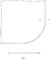
- FIG. 10 is a diagram schematically showing rotation trajectories C, P of the center edge 2C and the outer peripheral edge 2P in a state of being attached to the tool body 3.
- FIG. 11 is an enlarged view illustrating a lower right part in FIG. 10 .
- the rotation trajectory P of the main cutting edge 11P of the outer peripheral edge 2P protrudes more towards the outer side of a radial direction Dr of the tool body than the rotation trajectory C of the main cutting edge 12C of the center edge 2C.
- the outer peripheral edge 2P protrudes 0.02 mm more than the center edge 2C towards the outer side.
- contours of the rotation trajectories C and P approach each other as they move toward the rotation axis Z of the tool body 3.
- the cutting inserts 2 attached in a pair of two have the same shape such that the center edge 2C and the outer peripheral edge 2P are interchangeable.
- the first end surface 10 and the second end surface 20 of the cutting insert 2 have the same shape such that the front surface and the back surface are interchangeable.
- the cutting insert 2 may be used four times in total.
- Short sides (the fourth and eighth sides 14 and 24), which are not formed into cutting edges, have a dovetail shape, and they are bite into the insert pockets 91 and 92 of the tool body 3 in a wedge shape and is firmly restrained.
- the center axis O of the mounting hole 40 of the cutting insert 2 is not perpendicular to the rake surface but is inclined.
- the main cutting edge 11P of the outer peripheral edge 2P slightly bulges to an arc shape in a direction from the second end surface 20 to the first end surface 10.
- the rotation trajectory P of the main cutting edge 11P in the present disclosure is closer to an ideal imaginary cylindrical surface; as a result, a smooth finished surface can be formed.
- the outer peripheral edge 2P has a wiper cutting edge 12P for smoothing a finished surface of a material cut by the main cutting edge 11P
- the center edge 2C does not have such a wiper cutting edge.
- both the finished surface cut by the main cutting edge 11P of the outer peripheral edge 2P and the finished surface cut by the main cutting edge 12C of the center edge 2C can be smoothed by the wiper cutting edge 12P of the outer peripheral edge 2P.
- the wiper cutting edge 12P of the outer peripheral edge 2P is slightly inclined with respect to the main cutting edge 12C of the center edge 2C.
- the wiper cutting edge 12P is retracted from the main cutting edge in the advancing direction of the tool body 3.
- the wiper cutting edge 12P is used, the main cutting edge12C is retracted from the finished surface smoothed by the wiper cutting edge 12P.
- the wiper cutting edge 12P of the outer peripheral edge 2P is not easily damaged.
- the main cutting edge 12C of the center edge 2C is not easily damaged.
- center edge 24...eighth side, 30...peripheral side surface, 31...first side surface, 32...second side surface, 33...third side surface, 40...mounting hole, 91...insert pocket of center edge, 92...insert pocket of outer peripheral edge, C... rotation trajectory of center edge, Dz...axial direction of tool body, D ⁇ ...circumferential direction of tool body, O...center axis of mounting hole, P...rotation trajectory of outer peripheral edge, R1...first corner, R2...second corner, R3...third corner, R4...fourth corner, Z... rotation axis of tool body.
Landscapes
- Engineering & Computer Science (AREA)
- Mechanical Engineering (AREA)
- Milling Processes (AREA)
Abstract
Description
- The present disclosure relates to a cutting insert.
- An end mill is provided with a main cutting edge that cuts in the radial direction and an inner edge that cuts in the axial direction. If the inner edge extends from the outer peripheral surface of the tool body to the center of rotation, then it is possible to perform a drilling process that cuts directly below.
- An end mill capable of drilling is provided with, for example, a pair of cutting inserts. One of the cutting inserts is referred to as a center edge, which has an inner edge extending from the outer peripheral surface of the tool body to the center of rotation and a main cutting edge locating on the outer peripheral surface of the tool body. The other cutting insert is referred to as an outer peripheral edge, which has a main cutting edge on a side that is opposite to the main cutting edge of the center edge by 180°. Such an end mill needs two cutting inserts with different shapes, which results in inconvenience in tool management.
- In order to facilitate tool management, a cutting insert is proposed, where a cutting insert with one shape may be used as either the center edge or the outer peripheral edge (for example, please refer to Patent Document 1). According to
Patent Document 1, a cutting insert used as the center edge may be reused as the outer peripheral edge. - Patent Document 1: International Publication No.
2012/114848 - In
Patent Document 1, since the front and back surfaces of the cutting insert have asymmetric, complex shapes, the front and the back surfaces cannot be interchanged for further use. In view of this, an objective of the present disclosure is to provide a cutting insert that is economical and can be stably fixed to a tool body. - In a technical solution of the present disclosure, a cutting insert has a first end surface, a second end surface opposite to the first end surface, and a peripheral side surface connecting the first end surface and the second end surface, wherein a first edge line at which the first end surface intersects the peripheral side surface is a rectangle having a first side and a third side as long sides and a second side and a fourth side as short sides; a cutting edge is respectively formed at the first side, the second side and the third side respectively; no cutting edge is formed at the fourth side; a second edge line at which the second end surface intersects the peripheral side surface is a rectangle having an identical shape to the first edge line; a sixth side where a cutting edge is formed is opposite to the fourth side, and an eighth side where a cutting edge is not formed is opposite to the second side; the peripheral side surface includes a fourth side surface facing the fourth side and the sixth side; the fourth side surface extends from the first end surface to the second end surface and is inclined in a direction from the second side to the fourth side.
- According to the technical solution, the first side longer than the second side may be formed into an inner edge, the second side may be formed into a main cutting edge of a center edge, and the third side may be formed into the main cutting edge of an outer peripheral edge. Both the center edge and the outer peripheral edge may be composed of cutting inserts of the same shape, avoiding the need to provide two types of cutting inserts for the center edge and the outer peripheral edge. Since the cutting edge of the center edge and the cutting edge of the outer peripheral edge are formed at the first edge line and the second edge line respectively, the center edge and the outer peripheral edge can be interchanged and the cutting insert can be reused. The first edge line and the second edge line have the same shape, so the cutting insert can be reused by interchanging front and back surfaces. In other words, the same cutting insert can be used four times. In the cutting insert, the fourth side surface and the second end surface may define an acute angle, and one end of the cutting insert may form a wedge shape. When the cutting insert is fixed as the center edge or as the outer peripheral edge, the fourth side surface that does not form a cutting edge on a side of the first end surface can bite into a corner of an insert pocket of the tool body to be fixed. In this way, the present disclosure provides a cutting insert that is economical and can be stably fixed to the tool body.
- In the technical solution above, a pair of two cutting inserts may be attached to the tool body to form an end mill capable of drilling. The two cutting inserts may have an identical shape and may be interchangeable. One of the cutting inserts may be a center edge in which the first side may extend from the outer peripheral surface of the tool body to a rotation axis of the tool body in a state where the fourth side is attached in a direction along the rotation axis. The other of the cutting inserts may be an outer peripheral edge in which the second side may be located on the outer peripheral surface opposite to the center edge in a state where the third side may be attached in a direction along the rotation axis.
- According to the technical solution, since the first side extends to the rotation axis of the tool body, it is possible to perform a drilling process stably. It should be noted that even when the first side is just a little short of reaching the rotation axis, it is still possible to perform a drilling process while crushing a cutting residue with the tool body. However, such processing may put a heavy burden on the end mill.
- In the above technical solution, in addition to the main cutting edge of the center edge, a wiper cutting edge for smoothing a finished surface of a material cut by the main cutting edge of the outer peripheral edge may also be provided at the second side. Preferably, the wiper cutting edge of the outer peripheral edge may be inclined with respect to the main cutting edge of the center edge.
- In this implementation, even if the main cutting edge of the center edge and the wiper cutting edge of the outer peripheral edge are adjacent to each other, there may be an angular deviation between them. When the main cutting edge is used, the wiper cutting edge may be retracted from the main cutting edge in the advancing direction of the tool body. When the wiper cutting edge is used, the main cutting edge may be retracted from the finished surface smoothed by the wiper cutting edge. If the main cutting edge of the center edge and the wiper cutting edge are on the same plane, when one of the cutting edges is used, the other cutting edge may be damaged at the same time. For example, when a cutting insert used as a center edge is reused as an outer peripheral edge, a wiper cutting edge that has already been damaged before replacement will have to be used. Fortunately, such damage can be suppressed according to the technical solution.
- In the above technical solution, a mounting hole may be provided through which a fastening screw screwed into the tool body passes. The mounting hole may penetrate the first end surface and the second end surface, and a center axis of the mounting hole may be inclined with respect to the first end surface and the second end surface.
- According to the technical solution, during tightening, since one end of the wedge-shaped cutting insert may be pressed into the corner of the insert pocket of the tool body, the cutting insert may be more stably fixed to the tool body.
- In the above technical solution, the peripheral side surface may include a first side surface facing the first side. When viewed from the first side surface, the main cutting edge of the outer peripheral edge bulges in a direction from the second end surface to the first end surface.
- According to the technical solution, since the rotation trajectory of the main cutting edge is close to an ideal imaginary cylindrical surface, a smooth finished surface can be formed.
- In view of this, the present disclosure can provide a cutting insert that is economical and can be stably fixed to the tool body.
-
-
FIG. 1 is a perspective view illustrating an example of an end mill provided with a cutting insert according to an implementation of the present disclosure. -
FIG. 2 is a perspective view of the end mill shown inFIG. 1 viewed from an outer peripheral edge. -
FIG. 3 is a perspective view illustrating an example of the cutting insert according to an implementation of the present disclosure. -
FIG. 4 is a front view illustrating a first end surface of the cutting insert shown inFIG. 3 . -
FIG. 5 is a cross-sectional view taken along line V-V inFIG. 4 . -
FIG. 6 is a side view illustrating a main cutting edge of the outer peripheral edge shown inFIG. 3 . -
FIG. 7 is a side view illustrating a wiper cutting edge of the outer peripheral edge shown inFIG. 3 . -
FIG. 8 is a diagram illustrating a rake angle of the main cutting edge of a center edge in a state of being attached to a tool body. -
FIG. 9 is a diagram illustrating a rake angle of the main cutting edge of the outer peripheral edge in a state of being attached to the tool body. -
FIG. 10 is a diagram schematically showing rotation trajectories of the center edge and the outer peripheral edge in a state of being attached to the tool body. -
FIG. 11 is an enlarged view illustrating a lower right part inFIG. 10 . - The preferred implementations of the present disclosure are described below with reference to the accompanying drawings. It should be noted that in each figure, components marked with the same symbols have the same structure. In an implementation of the present disclosure, cutting
inserts 2 are attached to atool body 3 in a set of two to form anend mill 1 capable of drilling. - The set of two
cutting inserts 2 have the same shape and are interchangeable. In addition, in the cutting insert 2, afirst end surface 10 and asecond end surface 20 opposite to the first end surface are formed in the same shape and are interchangeable. Therefore, a cutting insert used as acenter edge 2C may be reused as an outerperipheral edge 2P. In addition, the cuttinginsert 2 may be reused by interchanging the first end surface 10 (front surface) and the second end surface 20 (back surface). That is, a cuttinginsert 2 may be used four times in total. - In the
cutting insert 2, afirst edge line 10R of thefirst end surface 10 is formed in a roughly rectangular shape, and asecond edge line 20R of thesecond end surface 20 is formed in the same roughly rectangular shape. At thefirst edge line 10R, cutting edges are formed at afirst side 11, asecond side 12 and athird side 13. On the other hand, no cutting edge is formed at afourth side 14 that is a short side. Thesecond edge line 20R has the same structure. Short sides (the fourth andeighth sides 14 and 24), at which no cutting edges are formed, have a dovetail shape; they bite into insert pockets 91 and 92 of thetool body 3 in a wedge shape and are firmly restrained. The structures are described in detail below with reference toFIGs. 1 to 11 . -
FIG. 1 is a perspective view illustrating an example of theend mill 1 provided with the cuttinginsert 2 according to an implementation of the present disclosure. As shown inFIG. 1 , thetool body 3 driven to rotate and thereplaceable cutting insert 2 are combined to form theend mill 1 with a replaceable cutter head. The insert pockets 91 and 92 are provided at a front end of thetool body 3. A feature of the cuttinginsert 2 of the present disclosure is that it may be fixed to either theinsert pocket 91 for the center edge or theinsert pocket 92 for the outer peripheral edge. As shown inFIG. 1 , thecenter edge 2C extends from an outerperipheral surface 3P of thetool body 3 to a rotation axis Z thereof. The outerperipheral edge 2P is located on an outerperipheral surface 3P on a side that is opposite to thecenter edge 2C by 180°. -
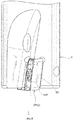
FIG. 2 is a perspective view of theend mill 1 shown inFIG. 1 viewed from the outerperipheral edge 2P. In the example shown in the figure, oneinsert pocket 92 for the outer peripheral edge is provided. There may also be two or more insert pockets 92 for the outer peripheral edge. In the example shown in the figure, a clamping means for fixing the cutting inserts 2 to the insert pockets 91 and 92 is configured as a screw-on type, in which afastening screw 9 is inserted into a mountinghole 40 of the cuttinginsert 2. It should be noted that thetool body 3 is not limited to the screw-on type, and may adopt a lever lock type, among others. -
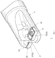
FIG. 3 is a perspective view illustrating an example of the cuttinginsert 2 according to an implementation of the present disclosure. There is no particular material limitation for the cuttinginsert 2, and various materials including cemented carbide may be used for the cutting insert. As shown inFIG. 3 , the cuttinginsert 2 has afirst end surface 10, asecond end surface 20 opposite to thefirst end surface 10 and aperipheral side surface 30 connecting thefirst end surface 10 and thesecond end surface 20. - The
first end surface 10 and thesecond end surface 20 have roughly the same shape and function. In theend mill 1, thefirst end surface 10 may be a rake surface and the second end surface 20 a restraining surface. Alternatively, thesecond end surface 20 may be a rake surface and the first end surface 10 a restraining surface. Therefore, thefirst end surface 10 is taken as a representative for detailed description, and thesecond end surface 20 may not be repeatedly described. - A
first edge line 10R at which thefirst end surface 10 intersects theperipheral side surface 30 is a rectangle having afirst side 11 and athird side 13 as long sides and asecond side 12 and afourth side 14 as short sides (refer toFIG. 4 ). Asecond edge line 20R at which thesecond end surface 20 intersects theperipheral side surface 30 has the same shape as thefirst edge line 10R, that is, the second edge line is a rectangle having afifth side 21 and aseventh side 23 as long sides and asixth side 22 and aneighth side 24 as short sides. In theperipheral side surface 30, thefirst side 11 and theseventh side 23 are opposite to each other, thesecond side 12 and theeighth side 24 are opposite to each other, and thethird side 13 and thefifth side 21 are opposite to each other. - At the
first edge line 10R, cutting edges are formed at thefirst side 11, thesecond side 12 and thethird side 13, but no cutting edge is formed at thefourth side 14. Similarly, at thesecond edge line 20R, cutting edges are formed at thefifth side 21, thesixth side 22 and theseventh side 23, but no cutting edge is formed at theeighth side 24. - Specifically, a
main cutting edge 11P of an outerperipheral edge 2P is formed at thefirst side 11; awiper cutting edge 12P of the outerperipheral edge 2P and amain cutting edge 12C of acenter edge 2C are adjacently formed at thesecond side 12; an inner edge 13C of thecenter edge 2C is formed at thethird side 13. Like thefirst edge line 10R, a main cutting edge of the outerperipheral edge 2P is formed at thefifth side 21; a wiper cutting edge of the outerperipheral edge 2P and a main cutting edge of thecenter edge 2C are formed adjacently at thesixth side 22; an inner edge of thecenter edge 2C is formed at theseventh side 23. - The
peripheral side surface 30 includes afirst side surface 31, asecond side surface 32, athird side surface 33 and afourth side surface 34 partitioned by a first corner R1, a second corner R2, a third corner R3 and a fourth corner R4 respectively. Thefirst side surface 31 is formed facing thefirst side 11 and theseventh side 23. Thesecond side surface 32 is formed facing thesecond side 12 and theeighth side 24. Thethird side surface 33 is formed facing thethird side 13 and thefifth side 21. Thefourth side surface 34 is formed facing thefourth side 14 and thesixth side 22. - The
fourth side surface 34 facing thefourth side 14 extends from thefirst end surface 10 to thesecond end surface 20 and is inclined in a direction from thesecond side 12 to thefourth side 14. Similarly, thesecond side surface 32 facing theeighth side 24 extends from thesecond end surface 20 to thefirst end surface 10 and is inclined in a direction from thesixth side 22 to theeighth side 24. Thefirst side surface 31 and thethird side surface 33 are formed into rough parallelograms where inner angles are not right angles. -
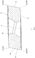
FIG. 4 is a front view illustrating thefirst end surface 10 of the cuttinginsert 2 shown inFIG. 3 . As shown inFIG. 4 , a mountinghole 40 is formed in thecutting insert 2, and the mountinghole 40 penetrates the center of thefirst end surface 10 and the center of thesecond end surface 20.FIG. 5 is a cross-sectional view taken along line V-V inFIG. 4 . As shown inFIG. 5 , a center axis O of the mountinghole 40 is not perpendicular to thefirst end surface 10 and thesecond end surface 20 but is inclined with respect to thefirst end surface 10 and thesecond end surface 20. In the example shown in the figure, the mountinghole 40 is formed in such a way that thesecond side surface 32 and thefourth side surface 34 are parallel to the center axis O. -
FIG. 6 is a side view illustrating themain cutting edge 11P of the outerperipheral edge 2P shown inFIG. 3 . As shown inFIG. 6 , when viewed from thefirst side surface 31, themain cutting edge 11P of the outerperipheral edge 2P slightly bulges to an arc shape in a direction from thesecond end surface 20 to thefirst end surface 10.FIG. 7 is a side view illustrating thewiper cutting edge 12P of the outerperipheral edge 2P shown inFIG. 3 . As shown inFIG. 7 , thewiper cutting edge 12P of the outerperipheral edge 2P constituting thesecond side 12 and themain cutting edge 12C of thecenter edge 2C are not collinear. Thewiper cutting edge 12P is slightly inclined with respect to themain cutting edge 12C. In the example shown in the figure, thewiper cutting edge 12P is inclined by 2° with respect to themain cutting edge 12C. -
FIG. 8 is a diagram illustrating a rake angle α of the main cutting edge 11C of thecenter edge 2C in a state of being attached to thetool body 3. In the example shown in the figure, thefourth side 14 of thecenter edge 2C is attached in a direction along the rotation axis Z of thetool body 3. As shown inFIG. 8 , the main cutting edge 11C of thecenter edge 2C is formed in a negative shape with a rake angle α of zero. -
FIG. 9 a diagram illustrating a rake angle β of themain cutting edge 11P of the outerperipheral edge 2P in a state of being attached to thetool body 3. In the example shown in the figure, thethird side 13 of the outerperipheral edge 2P is attached in a direction along the rotation axis Z. As shown inFIG. 9 , themain cutting edge 11P of the outerperipheral edge 2P is formed in a positive shape with a positive rake angle β. -
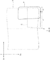
FIG. 10 is a diagram schematically showing rotation trajectories C, P of thecenter edge 2C and the outerperipheral edge 2P in a state of being attached to thetool body 3.FIG. 11 is an enlarged view illustrating a lower right part inFIG. 10 . As shown inFIG. 11 , on an outer peripheral side of thetool body 3, the rotation trajectory P of themain cutting edge 11P of the outerperipheral edge 2P protrudes more towards the outer side of a radial direction Dr of the tool body than the rotation trajectory C of themain cutting edge 12C of thecenter edge 2C. - In the example shown in the figure, in the radial direction Dr of the
tool body 3, the outerperipheral edge 2P protrudes 0.02 mm more than thecenter edge 2C towards the outer side. As shown inFIG. 10 , contours of the rotation trajectories C and P approach each other as they move toward the rotation axis Z of thetool body 3. In the example shown in the figure, the contours of the rotation trajectories C and P intersect at a position of L1:L2=8:2. - In the
cutting insert 2 configured as described above and theend mill 1 provided with the cuttinginsert 2 in an implementation of the present disclosure, the cutting inserts 2 attached in a pair of two have the same shape such that thecenter edge 2C and the outerperipheral edge 2P are interchangeable. In addition, thefirst end surface 10 and thesecond end surface 20 of the cuttinginsert 2 have the same shape such that the front surface and the back surface are interchangeable. Thus, the cuttinginsert 2 may be used four times in total. - Short sides (the fourth and
eighth sides 14 and 24), which are not formed into cutting edges, have a dovetail shape, and they are bite into the insert pockets 91 and 92 of thetool body 3 in a wedge shape and is firmly restrained. As shown inFIG. 5 , the center axis O of the mountinghole 40 of the cuttinginsert 2 is not perpendicular to the rake surface but is inclined. When tightening with thefastening screw 9, since the cuttinginsert 2 may be pushed by pressing thefourth side 14 of the wedge-shapedcutting insert 2 into the corner of theinsert pocket insert 2 can be more stably fixed to thetool body 3. - As shown in
FIG. 6 , when viewed from thefirst side surface 31, themain cutting edge 11P of the outerperipheral edge 2P slightly bulges to an arc shape in a direction from thesecond end surface 20 to thefirst end surface 10. Compared with amain cutting edge 11P that is not bulged, the rotation trajectory P of themain cutting edge 11P in the present disclosure is closer to an ideal imaginary cylindrical surface; as a result, a smooth finished surface can be formed. - The outer
peripheral edge 2P has awiper cutting edge 12P for smoothing a finished surface of a material cut by themain cutting edge 11P Thecenter edge 2C does not have such a wiper cutting edge. However, as shown inFIGS. 10 and11 , since the rotation trajectory P of the outerperipheral edge 2P is slightly ahead of the rotation trajectory C of thecenter edge 2C, both the finished surface cut by themain cutting edge 11P of the outerperipheral edge 2P and the finished surface cut by themain cutting edge 12C of thecenter edge 2C can be smoothed by thewiper cutting edge 12P of the outerperipheral edge 2P. - As shown in
FIG. 7 , thewiper cutting edge 12P of the outerperipheral edge 2P is slightly inclined with respect to themain cutting edge 12C of thecenter edge 2C. When themain cutting edge 12C is used, thewiper cutting edge 12P is retracted from the main cutting edge in the advancing direction of thetool body 3. When thewiper cutting edge 12P is used, the main cutting edge12C is retracted from the finished surface smoothed by thewiper cutting edge 12P. When the cuttinginsert 2 is used as thecenter edge 2C, thewiper cutting edge 12P of the outerperipheral edge 2P is not easily damaged. When the cuttinginsert 2 is used as the outerperipheral edge 2P, themain cutting edge 12C of thecenter edge 2C is not easily damaged. - The implementations described above are intended to facilitate the understanding of the present disclosure and are not for limiting and interpreting the present disclosure. The various elements and the arrangement, materials, conditions, shapes and dimensions thereof described in the implementations are not limited to the implementations, and may be appropriately changed. In addition, the structures shown in different implementations may be partially replaced or combined. Reference Numerals:
- 1...end mill, 2...cutting insert, 2C...center edge, 2P...outer peripheral edge, 3... tool body, 3P...outer peripheral surface, 9...fastening screw, 10...first end surface, 10R...first edge line, 11...first side, 11P...main cutting edge of outer peripheral edge, 12...second side, 12P...wiper cutting edge of outer peripheral edge, 12C...main cutting edge of center edge, 13...third side, 13C...inner edge of center edge, 14...fourth side, 20...second end surface, 20R...second edge line, 21...fifth side, 21P...main cutting edge of outer peripheral edge, 22...sixth side, 22P...wiper cutting edge of outer peripheral edge, 22C...main cutting edge of center edge, 23...seventh side, 23C... inner edge of center edge, 24...eighth side, 30...peripheral side surface, 31...first side surface, 32...second side surface, 33...third side surface, 40...mounting hole, 91...insert pocket of center edge, 92...insert pocket of outer peripheral edge, C... rotation trajectory of center edge, Dz...axial direction of tool body, Dθ...circumferential direction of tool body, O...center axis of mounting hole, P...rotation trajectory of outer peripheral edge, R1...first corner, R2...second corner, R3...third corner, R4...fourth corner, Z... rotation axis of tool body.
Claims (5)
- A cutting insert having a first end surface, a second end surface opposite to the first end surface, and a peripheral side surface connecting the first end surface and the second end surface, whereina first edge line at which the first end surface intersects the peripheral side surface is a rectangle having a first side and a third side as long sides and a second side and a fourth side as short sides; a cutting edge is respectively formed at the first side, the second side, and the third side; no cutting edge is formed at the fourth side;a second edge line at which the second end surface intersects the peripheral side surface is a rectangle having an identical shape to the first edge line; a sixth side where a cutting edge is formed is opposite to the fourth side, and an eighth side where a cutting edge is not formed is opposite to the second side;the peripheral side surface comprises a fourth side surface facing the fourth side and the sixth side;the fourth side surface extends from the first end surface to the second end surface and is inclined in a direction from the second side to the fourth side.
- The cutting insert according to claim 1, wherein a pair of two cutting inserts are attached to a tool body to form an end mill capable of drilling;the two cutting inserts have an identical shape and are interchangeable;one of the cutting inserts is a center edge in which the first side extends from an outer peripheral surface of the tool body to a rotation axis of the tool body in a state where the fourth side is attached in a direction along the rotation axis;the other of the cutting inserts is an outer peripheral edge in which the second side is located on an outer peripheral surface opposite to the center edge in a state where the third side is attached in the direction along the rotation axis.
- The cutting insert according to claim 2, whereinin addition to a main cutting edge of the center edge, a wiper cutting edge for smoothing a finished surface of a material cut by the main cutting edge of the outer peripheral edge is also provided at the second side;the wiper cutting edge of the outer peripheral edge is inclined with respect to the main cutting edge of the center edge.
- The cutting insert according to claim 2 or 3, whereinthe cutting insert is provided with a mounting hole through which a fastening screw screwed into the tool body passes;the mounting hole penetrates the first end surface and the second end surface, and a center axis of the mounting hole is inclined with respect to the first end surface and the second end surface.
- The cutting insert according to any one of claims 2 to 4, whereinthe peripheral side surface comprises a first side surface facing the first side;when viewed from the first side surface, the main cutting edge of the outer peripheral edge bulges in a direction from the second end surface to the first end surface.
Applications Claiming Priority (2)
| Application Number | Priority Date | Filing Date | Title |
|---|---|---|---|
| JP2019155770A JP6921385B2 (en) | 2019-08-28 | 2019-08-28 | Cutting insert |
| PCT/JP2020/032394 WO2021039913A1 (en) | 2019-08-28 | 2020-08-27 | Cutting insert |
Publications (3)
| Publication Number | Publication Date |
|---|---|
| EP3907030A1 true EP3907030A1 (en) | 2021-11-10 |
| EP3907030A4 EP3907030A4 (en) | 2022-10-19 |
| EP3907030B1 EP3907030B1 (en) | 2023-12-06 |
Family
ID=74674683
Family Applications (1)
| Application Number | Title | Priority Date | Filing Date |
|---|---|---|---|
| EP20858318.7A Active EP3907030B1 (en) | 2019-08-28 | 2020-08-27 | Cutting insert |
Country Status (5)
| Country | Link |
|---|---|
| US (1) | US11980952B2 (en) |
| EP (1) | EP3907030B1 (en) |
| JP (1) | JP6921385B2 (en) |
| CN (1) | CN113272089B (en) |
| WO (1) | WO2021039913A1 (en) |
Cited By (1)
| Publication number | Priority date | Publication date | Assignee | Title |
|---|---|---|---|---|
| EP4119271A1 (en) * | 2021-07-15 | 2023-01-18 | Tungaloy Corporation | Cutting insert, indexable rotary cutting tool, and body of the same |
Families Citing this family (4)
| Publication number | Priority date | Publication date | Assignee | Title |
|---|---|---|---|---|
| DE102021119229B4 (en) | 2021-07-26 | 2023-11-30 | Audi Aktiengesellschaft | Milling tool |
| JP7312364B1 (en) | 2022-10-31 | 2023-07-21 | 株式会社タンガロイ | Cutting tools and their tool bodies |
| JP7416305B1 (en) | 2023-03-27 | 2024-01-17 | 株式会社タンガロイ | Cutting inserts, bodies and cutting tools |
| JP7505634B1 (en) | 2023-12-28 | 2024-06-25 | 株式会社タンガロイ | CUTTING INSERT AND CUTTING TOOL HAVING SAME |
Family Cites Families (31)
| Publication number | Priority date | Publication date | Assignee | Title |
|---|---|---|---|---|
| JPS60161B2 (en) * | 1978-01-23 | 1985-01-07 | 住友電気工業株式会社 | throw away tool |
| US6939090B1 (en) * | 1999-08-17 | 2005-09-06 | Mitsubishi Materials Corporation | Throwaway tip and throwaway-type cutting tool |
| EP1077100B1 (en) * | 1999-08-17 | 2005-02-23 | Mitsubishi Materials Corporation | Throwaway tip and cutting tool |
| JP2001198724A (en) * | 2000-01-21 | 2001-07-24 | Mitsubishi Materials Corp | Indexable inserts and indexable milling tools |
| DE10144449A1 (en) * | 2001-09-10 | 2005-03-24 | Gustav Werthwein | Cutting insert for tools for machining workpieces and tools for the use of this insert |
| JP2004160606A (en) * | 2002-11-13 | 2004-06-10 | Osg Corp | Indexable inserts and indexable rotary cutting tools |
| FR2858946B1 (en) * | 2003-08-18 | 2006-12-15 | Safety | CUTTING PLATE FOR STRAWBERRY TREBLE |
| US7040844B1 (en) * | 2005-03-08 | 2006-05-09 | Mitsubishi Materials Corporation | Throwaway insert and throwaway-type rotary cutting tool |
| JP2007044779A (en) * | 2005-08-08 | 2007-02-22 | Sumitomo Electric Hardmetal Corp | Throw-away tip and milling cutter using the same |
| DE202008001348U1 (en) * | 2008-01-31 | 2009-06-10 | Kennametal Inc. | drilling |
| EP2394766A1 (en) * | 2010-06-10 | 2011-12-14 | Lamina Technologies SA | Double-sided indexable cutting insert and cutting tool |
| JP5196077B2 (en) * | 2010-06-21 | 2013-05-15 | 株式会社タンガロイ | Cutting inserts and cutting edge changeable turning tools |
| CN103025462B (en) * | 2010-08-11 | 2015-03-18 | 京瓷株式会社 | Cutting insert, cutting tool, and method for producing cut article using cutting insert and cutting tool |
| CN102958634B (en) * | 2010-10-05 | 2015-08-26 | 京瓷株式会社 | Cutting insert and cutting element and use the manufacture method of machining thing of this cutting element |
| JP5553128B2 (en) * | 2011-02-24 | 2014-07-16 | 株式会社タンガロイ | Cutting insert and cutting edge exchangeable end mill |
| JP6449783B2 (en) * | 2013-12-18 | 2019-01-09 | 京セラ株式会社 | Cutting insert, cutting tool, and manufacturing method of cut workpiece |
| EP3100811B1 (en) * | 2014-01-28 | 2022-09-21 | MOLDINO Tool Engineering, Ltd. | Insert and indexable rotary cutting tool |
| US10315258B2 (en) | 2014-02-26 | 2019-06-11 | Tungaloy Corporation | Cutting insert and cutting tool |
| US10022803B2 (en) * | 2014-04-22 | 2018-07-17 | Tungaloy Corporation | Cutting insert having constant-width wiper surface and cutting tool |
| US10245659B2 (en) * | 2014-06-27 | 2019-04-02 | Kyocera Corporation | Cutting insert, cutting tool, and method for manufacturing machined product |
| KR101517979B1 (en) * | 2014-07-08 | 2015-05-06 | 한국야금 주식회사 | Cutting insert and cutting tool for mounting the same |
| KR101631675B1 (en) * | 2014-11-28 | 2016-06-17 | 한국야금 주식회사 | Cutting insert and tool holder for coupling the same |
| EP3050655B1 (en) * | 2015-01-30 | 2017-03-22 | Sandvik Intellectual Property AB | A milling insert and a milling tool |
| JP6365363B2 (en) * | 2015-03-17 | 2018-08-01 | 三菱マテリアル株式会社 | Cutting insert, cutting insert group and cutting edge exchangeable cutting tool |
| CN107635704B (en) * | 2015-06-19 | 2020-01-07 | 株式会社泰珂洛 | Tool body and cutting tool |
| JP5967330B1 (en) * | 2015-09-25 | 2016-08-10 | 三菱日立ツール株式会社 | Cutting insert and cutting edge exchangeable rotary cutting tool |
| JP6691549B2 (en) * | 2015-10-28 | 2020-04-28 | 京セラ株式会社 | Drill holder, drill, and manufacturing method of machined product |
| DE112018003811T5 (en) * | 2017-07-26 | 2020-04-09 | Kyocera Corporation | CUTTING INSERT, CUTTING TOOL AND METHOD FOR PRODUCING A MACHINED PRODUCT |
| JP6562983B2 (en) * | 2017-08-10 | 2019-08-21 | 株式会社タンガロイ | Cutting insert and cutting tool |
| US11027342B2 (en) * | 2019-03-27 | 2021-06-08 | Iscar, Ltd. | Double-sided cutting insert having diagonally opposed raised corners and diagonally opposed lowered corners, and rotary cutting tool |
| JP6940832B1 (en) * | 2020-09-07 | 2021-09-29 | 株式会社タンガロイ | Rolling tool |
-
2019
- 2019-08-28 JP JP2019155770A patent/JP6921385B2/en active Active
-
2020
- 2020-08-27 CN CN202080007697.9A patent/CN113272089B/en active Active
- 2020-08-27 EP EP20858318.7A patent/EP3907030B1/en active Active
- 2020-08-27 WO PCT/JP2020/032394 patent/WO2021039913A1/en not_active Ceased
- 2020-08-27 US US17/422,224 patent/US11980952B2/en active Active
Cited By (1)
| Publication number | Priority date | Publication date | Assignee | Title |
|---|---|---|---|---|
| EP4119271A1 (en) * | 2021-07-15 | 2023-01-18 | Tungaloy Corporation | Cutting insert, indexable rotary cutting tool, and body of the same |
Also Published As
| Publication number | Publication date |
|---|---|
| JP2021030401A (en) | 2021-03-01 |
| JP6921385B2 (en) | 2021-08-18 |
| CN113272089B (en) | 2023-09-08 |
| CN113272089A (en) | 2021-08-17 |
| US11980952B2 (en) | 2024-05-14 |
| US20220080517A1 (en) | 2022-03-17 |
| EP3907030B1 (en) | 2023-12-06 |
| WO2021039913A1 (en) | 2021-03-04 |
| EP3907030A4 (en) | 2022-10-19 |
Similar Documents
| Publication | Publication Date | Title |
|---|---|---|
| EP3907030B1 (en) | Cutting insert | |
| EP0213494B1 (en) | Cutting tool insert having cutting edges with recesses | |
| US7086812B2 (en) | Cutting tool | |
| EP1635977B1 (en) | A milling tool with co-operating projections and recessess between the cutting insert and the holder | |
| EP0490122B1 (en) | Drill with replaceable cutting inserts | |
| US10076794B2 (en) | Star-shaped cutting insert for a front and back chamfering rotary milling cutter | |
| JPWO2007142224A1 (en) | Cutting tools and cutting inserts | |
| EP1635976B1 (en) | Indexable insert with corners with different radii | |
| US20130266384A1 (en) | Left-Handed and Right-Handed Cutting Tool | |
| US20220055126A1 (en) | Milling tool for milling workpieces | |
| EP0790878B1 (en) | Multi-handed milling cutter having indexable wedges and inserts | |
| US6761514B2 (en) | Hollow mill tool | |
| EP3838459A1 (en) | Cutting insert, cutting edge-replaceable rotary cutting tool and rotary cutting method | |
| CN100402211C (en) | Knives with inserts mounted on their edges | |
| CA2286507C (en) | End mill | |
| US20030039518A1 (en) | Cutting insert | |
| JP5564958B2 (en) | Replaceable cutting edge grooving tool and end face grooving method | |
| US4799834A (en) | Cutter insert for KEVLAR | |
| JPH06335816A (en) | Minimum diameter end mill | |
| JP2001079708A (en) | Mounting structure and mounting method of round throw-away tip | |
| JP2020116707A (en) | Indexable End Mill | |
| US20250214149A1 (en) | Cutting insert and cutting tool comprising the same | |
| JP2008100316A (en) | Cutting tools and finishing blade inserts | |
| JP2841167B2 (en) | Cutting tool for centering | |
| JPH0212015Y2 (en) |
Legal Events
| Date | Code | Title | Description |
|---|---|---|---|
| STAA | Information on the status of an ep patent application or granted ep patent |
Free format text: STATUS: THE INTERNATIONAL PUBLICATION HAS BEEN MADE |
|
| PUAI | Public reference made under article 153(3) epc to a published international application that has entered the european phase |
Free format text: ORIGINAL CODE: 0009012 |
|
| STAA | Information on the status of an ep patent application or granted ep patent |
Free format text: STATUS: REQUEST FOR EXAMINATION WAS MADE |
|
| 17P | Request for examination filed |
Effective date: 20210807 |
|
| AK | Designated contracting states |
Kind code of ref document: A1 Designated state(s): AL AT BE BG CH CY CZ DE DK EE ES FI FR GB GR HR HU IE IS IT LI LT LU LV MC MK MT NL NO PL PT RO RS SE SI SK SM TR |
|
| RIC1 | Information provided on ipc code assigned before grant |
Ipc: B23C 5/20 20060101ALI20220905BHEP Ipc: B23C 5/10 20060101AFI20220905BHEP |
|
| A4 | Supplementary search report drawn up and despatched |
Effective date: 20220915 |
|
| RIC1 | Information provided on ipc code assigned before grant |
Ipc: B23C 5/20 20060101ALI20220909BHEP Ipc: B23C 5/10 20060101AFI20220909BHEP |
|
| DAV | Request for validation of the european patent (deleted) | ||
| DAX | Request for extension of the european patent (deleted) | ||
| GRAP | Despatch of communication of intention to grant a patent |
Free format text: ORIGINAL CODE: EPIDOSNIGR1 |
|
| STAA | Information on the status of an ep patent application or granted ep patent |
Free format text: STATUS: GRANT OF PATENT IS INTENDED |
|
| INTG | Intention to grant announced |
Effective date: 20230704 |
|
| GRAS | Grant fee paid |
Free format text: ORIGINAL CODE: EPIDOSNIGR3 |
|
| GRAA | (expected) grant |
Free format text: ORIGINAL CODE: 0009210 |
|
| STAA | Information on the status of an ep patent application or granted ep patent |
Free format text: STATUS: THE PATENT HAS BEEN GRANTED |
|
| AK | Designated contracting states |
Kind code of ref document: B1 Designated state(s): AL AT BE BG CH CY CZ DE DK EE ES FI FR GB GR HR HU IE IS IT LI LT LU LV MC MK MT NL NO PL PT RO RS SE SI SK SM TR |
|
| REG | Reference to a national code |
Ref country code: GB Ref legal event code: FG4D |
|
| REG | Reference to a national code |
Ref country code: CH Ref legal event code: EP |
|
| REG | Reference to a national code |
Ref country code: DE Ref legal event code: R096 Ref document number: 602020022471 Country of ref document: DE |
|
| REG | Reference to a national code |
Ref country code: IE Ref legal event code: FG4D |
|
| REG | Reference to a national code |
Ref country code: LT Ref legal event code: MG9D |
|
| PG25 | Lapsed in a contracting state [announced via postgrant information from national office to epo] |
Ref country code: GR Free format text: LAPSE BECAUSE OF FAILURE TO SUBMIT A TRANSLATION OF THE DESCRIPTION OR TO PAY THE FEE WITHIN THE PRESCRIBED TIME-LIMIT Effective date: 20240307 |
|
| REG | Reference to a national code |
Ref country code: NL Ref legal event code: MP Effective date: 20231206 |
|
| PG25 | Lapsed in a contracting state [announced via postgrant information from national office to epo] |
Ref country code: LT Free format text: LAPSE BECAUSE OF FAILURE TO SUBMIT A TRANSLATION OF THE DESCRIPTION OR TO PAY THE FEE WITHIN THE PRESCRIBED TIME-LIMIT Effective date: 20231206 |
|
| PG25 | Lapsed in a contracting state [announced via postgrant information from national office to epo] |
Ref country code: ES Free format text: LAPSE BECAUSE OF FAILURE TO SUBMIT A TRANSLATION OF THE DESCRIPTION OR TO PAY THE FEE WITHIN THE PRESCRIBED TIME-LIMIT Effective date: 20231206 |
|
| PG25 | Lapsed in a contracting state [announced via postgrant information from national office to epo] |
Ref country code: LT Free format text: LAPSE BECAUSE OF FAILURE TO SUBMIT A TRANSLATION OF THE DESCRIPTION OR TO PAY THE FEE WITHIN THE PRESCRIBED TIME-LIMIT Effective date: 20231206 Ref country code: GR Free format text: LAPSE BECAUSE OF FAILURE TO SUBMIT A TRANSLATION OF THE DESCRIPTION OR TO PAY THE FEE WITHIN THE PRESCRIBED TIME-LIMIT Effective date: 20240307 Ref country code: ES Free format text: LAPSE BECAUSE OF FAILURE TO SUBMIT A TRANSLATION OF THE DESCRIPTION OR TO PAY THE FEE WITHIN THE PRESCRIBED TIME-LIMIT Effective date: 20231206 Ref country code: BG Free format text: LAPSE BECAUSE OF FAILURE TO SUBMIT A TRANSLATION OF THE DESCRIPTION OR TO PAY THE FEE WITHIN THE PRESCRIBED TIME-LIMIT Effective date: 20240306 |
|
| REG | Reference to a national code |
Ref country code: AT Ref legal event code: MK05 Ref document number: 1637935 Country of ref document: AT Kind code of ref document: T Effective date: 20231206 |
|
| PG25 | Lapsed in a contracting state [announced via postgrant information from national office to epo] |
Ref country code: NL Free format text: LAPSE BECAUSE OF FAILURE TO SUBMIT A TRANSLATION OF THE DESCRIPTION OR TO PAY THE FEE WITHIN THE PRESCRIBED TIME-LIMIT Effective date: 20231206 |
|
| PG25 | Lapsed in a contracting state [announced via postgrant information from national office to epo] |
Ref country code: SE Free format text: LAPSE BECAUSE OF FAILURE TO SUBMIT A TRANSLATION OF THE DESCRIPTION OR TO PAY THE FEE WITHIN THE PRESCRIBED TIME-LIMIT Effective date: 20231206 Ref country code: RS Free format text: LAPSE BECAUSE OF FAILURE TO SUBMIT A TRANSLATION OF THE DESCRIPTION OR TO PAY THE FEE WITHIN THE PRESCRIBED TIME-LIMIT Effective date: 20231206 Ref country code: NO Free format text: LAPSE BECAUSE OF FAILURE TO SUBMIT A TRANSLATION OF THE DESCRIPTION OR TO PAY THE FEE WITHIN THE PRESCRIBED TIME-LIMIT Effective date: 20240306 Ref country code: NL Free format text: LAPSE BECAUSE OF FAILURE TO SUBMIT A TRANSLATION OF THE DESCRIPTION OR TO PAY THE FEE WITHIN THE PRESCRIBED TIME-LIMIT Effective date: 20231206 Ref country code: LV Free format text: LAPSE BECAUSE OF FAILURE TO SUBMIT A TRANSLATION OF THE DESCRIPTION OR TO PAY THE FEE WITHIN THE PRESCRIBED TIME-LIMIT Effective date: 20231206 Ref country code: HR Free format text: LAPSE BECAUSE OF FAILURE TO SUBMIT A TRANSLATION OF THE DESCRIPTION OR TO PAY THE FEE WITHIN THE PRESCRIBED TIME-LIMIT Effective date: 20231206 |
|
| PG25 | Lapsed in a contracting state [announced via postgrant information from national office to epo] |
Ref country code: IS Free format text: LAPSE BECAUSE OF FAILURE TO SUBMIT A TRANSLATION OF THE DESCRIPTION OR TO PAY THE FEE WITHIN THE PRESCRIBED TIME-LIMIT Effective date: 20240406 |
|
| PG25 | Lapsed in a contracting state [announced via postgrant information from national office to epo] |
Ref country code: CZ Free format text: LAPSE BECAUSE OF FAILURE TO SUBMIT A TRANSLATION OF THE DESCRIPTION OR TO PAY THE FEE WITHIN THE PRESCRIBED TIME-LIMIT Effective date: 20231206 Ref country code: AT Free format text: LAPSE BECAUSE OF FAILURE TO SUBMIT A TRANSLATION OF THE DESCRIPTION OR TO PAY THE FEE WITHIN THE PRESCRIBED TIME-LIMIT Effective date: 20231206 |
|
| PG25 | Lapsed in a contracting state [announced via postgrant information from national office to epo] |
Ref country code: SK Free format text: LAPSE BECAUSE OF FAILURE TO SUBMIT A TRANSLATION OF THE DESCRIPTION OR TO PAY THE FEE WITHIN THE PRESCRIBED TIME-LIMIT Effective date: 20231206 |
|
| PG25 | Lapsed in a contracting state [announced via postgrant information from national office to epo] |
Ref country code: SM Free format text: LAPSE BECAUSE OF FAILURE TO SUBMIT A TRANSLATION OF THE DESCRIPTION OR TO PAY THE FEE WITHIN THE PRESCRIBED TIME-LIMIT Effective date: 20231206 Ref country code: SK Free format text: LAPSE BECAUSE OF FAILURE TO SUBMIT A TRANSLATION OF THE DESCRIPTION OR TO PAY THE FEE WITHIN THE PRESCRIBED TIME-LIMIT Effective date: 20231206 Ref country code: RO Free format text: LAPSE BECAUSE OF FAILURE TO SUBMIT A TRANSLATION OF THE DESCRIPTION OR TO PAY THE FEE WITHIN THE PRESCRIBED TIME-LIMIT Effective date: 20231206 Ref country code: IT Free format text: LAPSE BECAUSE OF FAILURE TO SUBMIT A TRANSLATION OF THE DESCRIPTION OR TO PAY THE FEE WITHIN THE PRESCRIBED TIME-LIMIT Effective date: 20231206 Ref country code: IS Free format text: LAPSE BECAUSE OF FAILURE TO SUBMIT A TRANSLATION OF THE DESCRIPTION OR TO PAY THE FEE WITHIN THE PRESCRIBED TIME-LIMIT Effective date: 20240406 Ref country code: EE Free format text: LAPSE BECAUSE OF FAILURE TO SUBMIT A TRANSLATION OF THE DESCRIPTION OR TO PAY THE FEE WITHIN THE PRESCRIBED TIME-LIMIT Effective date: 20231206 Ref country code: CZ Free format text: LAPSE BECAUSE OF FAILURE TO SUBMIT A TRANSLATION OF THE DESCRIPTION OR TO PAY THE FEE WITHIN THE PRESCRIBED TIME-LIMIT Effective date: 20231206 Ref country code: AT Free format text: LAPSE BECAUSE OF FAILURE TO SUBMIT A TRANSLATION OF THE DESCRIPTION OR TO PAY THE FEE WITHIN THE PRESCRIBED TIME-LIMIT Effective date: 20231206 |
|
| PG25 | Lapsed in a contracting state [announced via postgrant information from national office to epo] |
Ref country code: PL Free format text: LAPSE BECAUSE OF FAILURE TO SUBMIT A TRANSLATION OF THE DESCRIPTION OR TO PAY THE FEE WITHIN THE PRESCRIBED TIME-LIMIT Effective date: 20231206 Ref country code: PT Free format text: LAPSE BECAUSE OF FAILURE TO SUBMIT A TRANSLATION OF THE DESCRIPTION OR TO PAY THE FEE WITHIN THE PRESCRIBED TIME-LIMIT Effective date: 20240408 |
|
| PG25 | Lapsed in a contracting state [announced via postgrant information from national office to epo] |
Ref country code: PT Free format text: LAPSE BECAUSE OF FAILURE TO SUBMIT A TRANSLATION OF THE DESCRIPTION OR TO PAY THE FEE WITHIN THE PRESCRIBED TIME-LIMIT Effective date: 20240408 Ref country code: PL Free format text: LAPSE BECAUSE OF FAILURE TO SUBMIT A TRANSLATION OF THE DESCRIPTION OR TO PAY THE FEE WITHIN THE PRESCRIBED TIME-LIMIT Effective date: 20231206 |
|
| REG | Reference to a national code |
Ref country code: DE Ref legal event code: R097 Ref document number: 602020022471 Country of ref document: DE |
|
| PG25 | Lapsed in a contracting state [announced via postgrant information from national office to epo] |
Ref country code: DK Free format text: LAPSE BECAUSE OF FAILURE TO SUBMIT A TRANSLATION OF THE DESCRIPTION OR TO PAY THE FEE WITHIN THE PRESCRIBED TIME-LIMIT Effective date: 20231206 |
|
| PLBE | No opposition filed within time limit |
Free format text: ORIGINAL CODE: 0009261 |
|
| STAA | Information on the status of an ep patent application or granted ep patent |
Free format text: STATUS: NO OPPOSITION FILED WITHIN TIME LIMIT |
|
| PG25 | Lapsed in a contracting state [announced via postgrant information from national office to epo] |
Ref country code: SI Free format text: LAPSE BECAUSE OF FAILURE TO SUBMIT A TRANSLATION OF THE DESCRIPTION OR TO PAY THE FEE WITHIN THE PRESCRIBED TIME-LIMIT Effective date: 20231206 |
|
| PG25 | Lapsed in a contracting state [announced via postgrant information from national office to epo] |
Ref country code: SI Free format text: LAPSE BECAUSE OF FAILURE TO SUBMIT A TRANSLATION OF THE DESCRIPTION OR TO PAY THE FEE WITHIN THE PRESCRIBED TIME-LIMIT Effective date: 20231206 Ref country code: DK Free format text: LAPSE BECAUSE OF FAILURE TO SUBMIT A TRANSLATION OF THE DESCRIPTION OR TO PAY THE FEE WITHIN THE PRESCRIBED TIME-LIMIT Effective date: 20231206 |
|
| 26N | No opposition filed |
Effective date: 20240909 |
|
| REG | Reference to a national code |
Ref country code: CH Ref legal event code: PL |
|
| PG25 | Lapsed in a contracting state [announced via postgrant information from national office to epo] |
Ref country code: LU Free format text: LAPSE BECAUSE OF NON-PAYMENT OF DUE FEES Effective date: 20240827 |
|
| GBPC | Gb: european patent ceased through non-payment of renewal fee |
Effective date: 20240827 |
|
| PG25 | Lapsed in a contracting state [announced via postgrant information from national office to epo] |
Ref country code: MC Free format text: LAPSE BECAUSE OF FAILURE TO SUBMIT A TRANSLATION OF THE DESCRIPTION OR TO PAY THE FEE WITHIN THE PRESCRIBED TIME-LIMIT Effective date: 20231206 Ref country code: CH Free format text: LAPSE BECAUSE OF NON-PAYMENT OF DUE FEES Effective date: 20240831 |
|
| REG | Reference to a national code |
Ref country code: BE Ref legal event code: MM Effective date: 20240831 |
|
| PG25 | Lapsed in a contracting state [announced via postgrant information from national office to epo] |
Ref country code: GB Free format text: LAPSE BECAUSE OF NON-PAYMENT OF DUE FEES Effective date: 20240827 |
|
| PG25 | Lapsed in a contracting state [announced via postgrant information from national office to epo] |
Ref country code: BE Free format text: LAPSE BECAUSE OF NON-PAYMENT OF DUE FEES Effective date: 20240831 |
|
| PG25 | Lapsed in a contracting state [announced via postgrant information from national office to epo] |
Ref country code: FR Free format text: LAPSE BECAUSE OF NON-PAYMENT OF DUE FEES Effective date: 20240831 |
|
| PG25 | Lapsed in a contracting state [announced via postgrant information from national office to epo] |
Ref country code: IE Free format text: LAPSE BECAUSE OF NON-PAYMENT OF DUE FEES Effective date: 20240827 |
|
| PG25 | Lapsed in a contracting state [announced via postgrant information from national office to epo] |
Ref country code: FI Free format text: LAPSE BECAUSE OF FAILURE TO SUBMIT A TRANSLATION OF THE DESCRIPTION OR TO PAY THE FEE WITHIN THE PRESCRIBED TIME-LIMIT Effective date: 20231207 |
|
| PGFP | Annual fee paid to national office [announced via postgrant information from national office to epo] |
Ref country code: DE Payment date: 20250702 Year of fee payment: 6 |
|
| PG25 | Lapsed in a contracting state [announced via postgrant information from national office to epo] |
Ref country code: CY Free format text: LAPSE BECAUSE OF FAILURE TO SUBMIT A TRANSLATION OF THE DESCRIPTION OR TO PAY THE FEE WITHIN THE PRESCRIBED TIME-LIMIT; INVALID AB INITIO Effective date: 20200827 |
|
| PG25 | Lapsed in a contracting state [announced via postgrant information from national office to epo] |
Ref country code: HU Free format text: LAPSE BECAUSE OF FAILURE TO SUBMIT A TRANSLATION OF THE DESCRIPTION OR TO PAY THE FEE WITHIN THE PRESCRIBED TIME-LIMIT; INVALID AB INITIO Effective date: 20200827 |