EP3906802A1 - Buckle tongue with blocking element - Google Patents
Buckle tongue with blocking element Download PDFInfo
- Publication number
- EP3906802A1 EP3906802A1 EP21172607.0A EP21172607A EP3906802A1 EP 3906802 A1 EP3906802 A1 EP 3906802A1 EP 21172607 A EP21172607 A EP 21172607A EP 3906802 A1 EP3906802 A1 EP 3906802A1
- Authority
- EP
- European Patent Office
- Prior art keywords
- belt strap
- tongue
- blocking element
- belt
- recesses
- Prior art date
- Legal status (The legal status is an assumption and is not a legal conclusion. Google has not performed a legal analysis and makes no representation as to the accuracy of the status listed.)
- Granted
Links
Images

Classifications
-
- A—HUMAN NECESSITIES
- A44—HABERDASHERY; JEWELLERY
- A44B—BUTTONS, PINS, BUCKLES, SLIDE FASTENERS, OR THE LIKE
- A44B11/00—Buckles; Similar fasteners for interconnecting straps or the like, e.g. for safety belts
- A44B11/25—Buckles; Similar fasteners for interconnecting straps or the like, e.g. for safety belts with two or more separable parts
- A44B11/2503—Safety buckles
- A44B11/2546—Details
- A44B11/2553—Attachment of buckle to strap
- A44B11/2557—Attachment of buckle to strap with strap length adjustment
-
- A—HUMAN NECESSITIES
- A44—HABERDASHERY; JEWELLERY
- A44B—BUTTONS, PINS, BUCKLES, SLIDE FASTENERS, OR THE LIKE
- A44B11/00—Buckles; Similar fasteners for interconnecting straps or the like, e.g. for safety belts
- A44B11/25—Buckles; Similar fasteners for interconnecting straps or the like, e.g. for safety belts with two or more separable parts
- A44B11/2503—Safety buckles
- A44B11/2546—Details
- A44B11/2553—Attachment of buckle to strap
-
- A—HUMAN NECESSITIES
- A44—HABERDASHERY; JEWELLERY
- A44B—BUTTONS, PINS, BUCKLES, SLIDE FASTENERS, OR THE LIKE
- A44B11/00—Buckles; Similar fasteners for interconnecting straps or the like, e.g. for safety belts
- A44B11/25—Buckles; Similar fasteners for interconnecting straps or the like, e.g. for safety belts with two or more separable parts
- A44B11/2503—Safety buckles
- A44B11/2546—Details
- A44B11/2561—Tongue elements
-
- B—PERFORMING OPERATIONS; TRANSPORTING
- B60—VEHICLES IN GENERAL
- B60R—VEHICLES, VEHICLE FITTINGS, OR VEHICLE PARTS, NOT OTHERWISE PROVIDED FOR
- B60R22/00—Safety belts or body harnesses in vehicles
- B60R22/18—Anchoring devices
-
- B—PERFORMING OPERATIONS; TRANSPORTING
- B60—VEHICLES IN GENERAL
- B60R—VEHICLES, VEHICLE FITTINGS, OR VEHICLE PARTS, NOT OTHERWISE PROVIDED FOR
- B60R22/00—Safety belts or body harnesses in vehicles
- B60R22/18—Anchoring devices
- B60R2022/1812—Connections between seat belt and buckle tongue
Definitions
- the present invention relates to a buckle tongue comprising a tongue body, wherein the tongue body extends in an insertion direction, forms a belt slot that extends transversely to the insertion direction and is provided for guiding a belt strap through it, and has a contact section, wherein the belt strap rests against the contact section at least in a load position, and wherein the contact section has several recesses, which in the load position minimize the belt strap slipping transversely to the insertion direction or preferably even completely prevent it from doing so, and with a blocking element that is movably arranged in the tongue body, wherein in an unloaded pass-through position of the blocking element, the belt strap can be moved through the belt slot, and in the load position brought about by a tensile force introduced into the belt strap, the movability of the belt strap is at least inhibited by means of the blocking element.
- a buckle tongue with the aforementioned features is known from DE 10 2013 216 326 A1 , wherein the tongue body has depressions that are oriented in the longitudinal direction of the belt strap and against which the belt strap already rests in the pass-through position.
- the recesses are formed as cross grooves or the surface having the recesses also has a high coefficient of friction in the longitudinal direction of the belt strap, the tongue body can negatively counteract a simple movement of the buckle tongue along the belt strap in the pass-through position.
- the object of the present invention is therefore to eliminate the disadvantages described with reference to the prior art and in particular to specify a buckle tongue that can be moved along the belt strap in a simple manner, i.e., without much resistance, in the pass-through position, whereas in the load position and in particular before a complete clamping of the belt strap is reached, a the belt strap is not movable transversely to the insertion direction along the tongue body.
- a buckle tongue having the features mentioned at the outset and with which the blocking element is arranged in the pass-through position between the belt strap and the contact section having the recesses, so that the belt strap does not rest against the recesses in the pass-through position.
- the basic idea of the invention thus provides that the belt strap is spaced from the recesses by the blocking element in the pass-through position of the blocking element, whereas after a deflection of the blocking element from the pass-through position in the direction of the load position and at the latest shortly before reaching the maximum load position, the belt strap comes into contact with the recesses and in particular is drawn into them.
- the interaction between the belt strap loaded with a relatively high tensile force and the recesses prevents the belt strap from slipping transversely to the insertion direction along the tongue body.
- Such slipping of the belt strap in the belt slot transversely to the insertion direction is also referred to as "bunching.”
- several (at least two), preferably at least three or even at least four, recesses that are arranged next to one another, into which the belt strap is drawn in the load position, are provided in the contact section.
- the tongue body consists, for example, of a metal tongue plate and of a plastic cover partially surrounding the tongue plate, in particular in the region of the belt slot, wherein the cover has the recesses in a preferred embodiment.
- the blocking element can, for example, be mounted so as to be linearly movable (displaceable) in/on the tongue body. However, it is preferred that the blocking element is mounted pivotably in/on the tongue body. Thereby, the blocking element is pivoted from the pass-through position into the load position by the belt strap.
- the end tongue deflects the belt strap in a loop-like manner, so that the belt strap is divided into a shoulder belt section and a lap belt section.
- this section of the belt strap deflected in a loop-like manner acts with a tensile force from the shoulder belt section and/or from the lap belt section onto the blocking element and transfers it from the pass-through position into the load position.
- the blocking element has, in particular, a clamping section and an actuating section, wherein the belt strap transfers the blocking element from the pass-through position into the load position by acting on the actuating section, and wherein the belt strap is clamped in the load position between the tongue body and the clamping section of the blocking element.
- the clamping section and the actuating section are in particular integrally formed on a common component. In the pass-through position, the clamping section is spaced from a pressing section formed by a surface section of the tongue body, such that the belt strap guided through between the clamping section and the pressing section is freely movable in the pass-through position.
- the clamping section moves toward the pressing section of the tongue body and finally presses the belt strap arranged therebetween onto the pressing section.
- the actuating section of the blocking element is arranged between the belt strap and the contact section.
- a recess is formed between the clamping section and the actuating section of the blocking element, wherein the blocking element in the load position assumes such a position that the tongue body is arranged in this recess between the clamping section and the actuating section in the load position, so that the contact section having the recess extends through the blocking element.
- the recesses are in particular arranged in such a way that they delimit the belt slot.
- the recesses that delimit the belt slot are thus arranged in such a section (for example on an edge or surface) of the tongue body.
- the depths of the depressions formed by the recesses thus extend in the insertion direction, while the recesses do not have any substantial extent in the longitudinal direction of the belt strap, i.e., transversely to the belt slot.
- the regions of the contact section between the recesses thus together form a plurality of tooth-shaped projections.
- the recesses are arranged at a point at which particularly large tensile forces draw the belt strap into the recesses. The belt strap is thus prevented particularly effectively from slipping transversely to the insertion direction.
- Figure 1 shows a tongue body 3 of a buckle tongue 1 shown in Figures 2 to 4 .
- the tongue body 3 comprises a metal tongue plate 5 and a plastic cover 6 partially surrounding the tongue plate 5.
- the tongue body 3 extends in an insertion direction 2 and has a belt slot 4.
- the belt slot 4 extends transversely to the insertion direction 2 and is provided for receiving a belt strap 12 shown in Figure 4 .
- the cover 6 forms a contact section 8 that delimits the belt slot 4 and has several recesses 9.
- the buckle tongue 1 also comprises a blocking element 7 that is shown in Figure 2 in its pass-through position and in Figure 3 in its load position.
- the integrally formed blocking element 7 has a clamping section 10 and an actuating section 11. A recess is formed between the clamping section 10 and the actuating section 11.
- the actuating section 11 is arranged in the pass-through position such that the belt strap 12 (not shown in Figure 2 ) does not come into contact with the recesses 9 of the contact section 8. In the pass-through position, the belt strap 12 can, however, be guided freely movably through the belt slot 4.
- the belt strap 12 acts on the actuating section 11 of the blocking element 7, whereby the blocking element 7 is pivoted into the load position.
- the belt strap 12 is pressed by the clamping section 10 of the blocking element 7 onto a pressing section of the tongue body 3, whereby the mobility of the belt strap 12 is decreased or completely reduced.
- the recesses 9 are released by the pivoting of the actuating section 11, wherein the belt strap 12 comes into contact with the contact section 8 and is drawn into the recesses 9 as indicated in Figure 4 by the arrows.
- the contact section 8 with the recesses 9 extends through the blocking element 11 so to speak, whereby the contact section 8 with the recesses 9 comes into contact with the belt strap 12. Since the recesses 9 delimit the belt slot 4 at least in the load position, the belt strap 12 with its section deflected in a loop-like manner acts on the recesses 9, so that the belt strap 12 is drawn into the recesses 9 with a high force. In their depths, the recesses 9 therefore extend in the insertion direction 2 and not substantially in the belt strap profile direction, so that the contact section 8 forms tooth-like projections between the recesses 9. Slipping of the belt strap 12 transversely to the insertion direction 2 is thus effectively avoided.
Landscapes
- Engineering & Computer Science (AREA)
- Mechanical Engineering (AREA)
- Buckles (AREA)
- Automotive Seat Belt Assembly (AREA)
Abstract
Description
- The present invention relates to a buckle tongue comprising a tongue body, wherein the tongue body extends in an insertion direction, forms a belt slot that extends transversely to the insertion direction and is provided for guiding a belt strap through it, and has a contact section, wherein the belt strap rests against the contact section at least in a load position, and wherein the contact section has several recesses, which in the load position minimize the belt strap slipping transversely to the insertion direction or preferably even completely prevent it from doing so, and with a blocking element that is movably arranged in the tongue body, wherein in an unloaded pass-through position of the blocking element, the belt strap can be moved through the belt slot, and in the load position brought about by a tensile force introduced into the belt strap, the movability of the belt strap is at least inhibited by means of the blocking element.
- A buckle tongue with the aforementioned features is known from
DE 10 2013 216 326 A1 , wherein the tongue body has depressions that are oriented in the longitudinal direction of the belt strap and against which the belt strap already rests in the pass-through position. In particular if the recesses are formed as cross grooves or the surface having the recesses also has a high coefficient of friction in the longitudinal direction of the belt strap, the tongue body can negatively counteract a simple movement of the buckle tongue along the belt strap in the pass-through position. - The object of the present invention is therefore to eliminate the disadvantages described with reference to the prior art and in particular to specify a buckle tongue that can be moved along the belt strap in a simple manner, i.e., without much resistance, in the pass-through position, whereas in the load position and in particular before a complete clamping of the belt strap is reached, a the belt strap is not movable transversely to the insertion direction along the tongue body.
- The object is achieved by a buckle tongue with the features of the independent claim. Advantageous developments of the buckle tongue are specified in the dependent claims and in the description, wherein individual features of the advantageous developments can be combined with one another as desired in a technically sensible manner.
- The object is achieved in particular by a buckle tongue having the features mentioned at the outset and with which the blocking element is arranged in the pass-through position between the belt strap and the contact section having the recesses, so that the belt strap does not rest against the recesses in the pass-through position.
- The basic idea of the invention thus provides that the belt strap is spaced from the recesses by the blocking element in the pass-through position of the blocking element, whereas after a deflection of the blocking element from the pass-through position in the direction of the load position and at the latest shortly before reaching the maximum load position, the belt strap comes into contact with the recesses and in particular is drawn into them. The interaction between the belt strap loaded with a relatively high tensile force and the recesses prevents the belt strap from slipping transversely to the insertion direction along the tongue body. Such slipping of the belt strap in the belt slot transversely to the insertion direction is also referred to as "bunching." Thus, several (at least two), preferably at least three or even at least four, recesses that are arranged next to one another, into which the belt strap is drawn in the load position, are provided in the contact section.
- The tongue body consists, for example, of a metal tongue plate and of a plastic cover partially surrounding the tongue plate, in particular in the region of the belt slot, wherein the cover has the recesses in a preferred embodiment.
- The blocking element can, for example, be mounted so as to be linearly movable (displaceable) in/on the tongue body. However, it is preferred that the blocking element is mounted pivotably in/on the tongue body. Thereby, the blocking element is pivoted from the pass-through position into the load position by the belt strap.
- In the buckled state, the end tongue deflects the belt strap in a loop-like manner, so that the belt strap is divided into a shoulder belt section and a lap belt section. In the case of a load, this section of the belt strap deflected in a loop-like manner acts with a tensile force from the shoulder belt section and/or from the lap belt section onto the blocking element and transfers it from the pass-through position into the load position.
- The blocking element has, in particular, a clamping section and an actuating section, wherein the belt strap transfers the blocking element from the pass-through position into the load position by acting on the actuating section, and wherein the belt strap is clamped in the load position between the tongue body and the clamping section of the blocking element. The clamping section and the actuating section are in particular integrally formed on a common component. In the pass-through position, the clamping section is spaced from a pressing section formed by a surface section of the tongue body, such that the belt strap guided through between the clamping section and the pressing section is freely movable in the pass-through position. When the blocking element is deflected by the belt strap acting on the actuating section, the clamping section moves toward the pressing section of the tongue body and finally presses the belt strap arranged therebetween onto the pressing section.
- In order to prevent the belt strap from already resting against the recesses of the contact section in the pass-through position, it is provided in one embodiment that the actuating section of the blocking element is arranged between the belt strap and the contact section. In particular when the blocking element is pivotably mounted in/on the tongue body, a recess is formed between the clamping section and the actuating section of the blocking element, wherein the blocking element in the load position assumes such a position that the tongue body is arranged in this recess between the clamping section and the actuating section in the load position, so that the contact section having the recess extends through the blocking element.
- The recesses are in particular arranged in such a way that they delimit the belt slot. The recesses that delimit the belt slot are thus arranged in such a section (for example on an edge or surface) of the tongue body. The depths of the depressions formed by the recesses thus extend in the insertion direction, while the recesses do not have any substantial extent in the longitudinal direction of the belt strap, i.e., transversely to the belt slot. The regions of the contact section between the recesses thus together form a plurality of tooth-shaped projections. In this way, the recesses are arranged at a point at which particularly large tensile forces draw the belt strap into the recesses. The belt strap is thus prevented particularly effectively from slipping transversely to the insertion direction. This specific arrangement of the recesses is also considered a separate invention without the features of the solution described above. Thus, in particular, several recesses arranged next to one another can be utilized at a section of the tongue body extending through the blocking element, wherein the recesses directly delimit the belt slot without the spacing of the belt strap having to be utilized by the blocking element in the pass-through position.
- The invention and the technical environment are explained below by way of example with reference to the figures. The following are shown schematically:
-
Figure 1 : a tongue body of a buckle tongue, -
Figure 2 : the buckle tongue according toFigure 1 with a movably mounted blocking element in a pass-through position, -
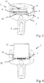
Figure 3 : the buckle tongue according toFigure 2 with the blocking element in a load position, and -
Figure 4 : the buckle tongue in the load position with a belt strap. -
Figure 1 shows atongue body 3 of abuckle tongue 1 shown inFigures 2 to 4 . Thetongue body 3 comprises ametal tongue plate 5 and aplastic cover 6 partially surrounding thetongue plate 5. Thetongue body 3 extends in aninsertion direction 2 and has abelt slot 4. Thebelt slot 4 extends transversely to theinsertion direction 2 and is provided for receiving abelt strap 12 shown inFigure 4 . - The
cover 6 forms acontact section 8 that delimits thebelt slot 4 and hasseveral recesses 9. - The
buckle tongue 1 also comprises ablocking element 7 that is shown inFigure 2 in its pass-through position and inFigure 3 in its load position. The integrally formed blockingelement 7 has aclamping section 10 and an actuatingsection 11. A recess is formed between theclamping section 10 and the actuatingsection 11. - As can be seen from
Figure 2 , the actuatingsection 11 is arranged in the pass-through position such that the belt strap 12 (not shown inFigure 2 ) does not come into contact with therecesses 9 of thecontact section 8. In the pass-through position, thebelt strap 12 can, however, be guided freely movably through thebelt slot 4. - When a tensile force is introduced into the belt strap, the
belt strap 12 acts on the actuatingsection 11 of theblocking element 7, whereby theblocking element 7 is pivoted into the load position. In the load position, thebelt strap 12 is pressed by theclamping section 10 of the blockingelement 7 onto a pressing section of thetongue body 3, whereby the mobility of thebelt strap 12 is decreased or completely reduced. At the same time, therecesses 9 are released by the pivoting of the actuatingsection 11, wherein thebelt strap 12 comes into contact with thecontact section 8 and is drawn into therecesses 9 as indicated inFigure 4 by the arrows. - By the pivoting of the blocking
element 7, thecontact section 8 with therecesses 9 extends through the blockingelement 11 so to speak, whereby thecontact section 8 with therecesses 9 comes into contact with thebelt strap 12. Since therecesses 9 delimit thebelt slot 4 at least in the load position, thebelt strap 12 with its section deflected in a loop-like manner acts on therecesses 9, so that thebelt strap 12 is drawn into therecesses 9 with a high force. In their depths, therecesses 9 therefore extend in theinsertion direction 2 and not substantially in the belt strap profile direction, so that thecontact section 8 forms tooth-like projections between therecesses 9. Slipping of thebelt strap 12 transversely to theinsertion direction 2 is thus effectively avoided. -
- 1
- Buckle tongue
- 2
- Insertion direction
- 3
- Tongue body
- 4
- Belt slot
- 5
- Tongue plate
- 6
- Cover
- 7
- Blocking element
- 8
- Contact section
- 9
- Recess
- 10
- Clamping section
- 11
- Actuating section
- 12
- Belt strap
Claims (9)
- Buckle tongue (1) comprising- a tongue body (3), wherein the tongue body (3)• extends in an insertion direction (2),• forms a belt slot (4) that extends transversely to the insertion direction (2) and is provided for guiding a belt strap through it, and• has a contact section (8), wherein the belt strap (12) rests against the contact section (8) at least in a load position, wherein the contact section (8) has several recesses (9) that in the load position minimize slipping of the belt strap (12) transversely to the insertion direction (2), and- a blocking element (7) movably arranged in the tongue body (3), wherein the belt strap (12) can be moved through the belt slot (4) in an unloaded pass-through position of the blocking element (7) and is at least inhibited in its mobility by means of the blocking element (7) in the load position brought about by a tensile force introduced into the belt strap (12),characterized in that
in the pass-through position, the blocking element (7) is arranged between the belt strap (12) and the contact section (8) having the recesses (9), so that the belt strap (12) does not rest against the recesses (9) in the pass-through position. - Buckle tongue (1) according to claim 1, wherein the blocking element (7) has a clamping section (10) and an actuating section (11), wherein the belt strap (12) transfers the blocking element (7) from the pass-through position into the load position by acting on the actuating section (11) and the belt strap (12) is blocked between the tongue body (3) and the clamping section (10) in the load position.
- Buckle tongue (1) according to claim 2, wherein in the pass-through position, the actuating section (11) is arranged between the belt strap (12) and the contact section (8).
- Buckle tongue (1) according to claim 3, wherein the part of the tongue body (3) forming the contact section (8) extends through the blocking element (7) between the clamping section (10) and the actuating section (11) in the load position.
- Buckle tongue (1) according to one of the preceding claims, characterized in that the recesses (9) delimit the belt slot (4).
- Buckle tongue (1) according to one of the preceding claims, wherein the contact section (8) has at least three recesses (9) that are arranged next to one another and into which the belt strap (12) is drawn in the load position.
- Buckle tongue (1) according to one of the preceding claims, wherein the tongue body (3) has a metal tongue plate (5) and a plastic cover (6) that partially surrounds the tongue plate (5), wherein the cover (6) has the recesses (9).
- Buckle tongue (1) according to one of the preceding claims, wherein the blocking element (7) is arranged in the tongue body (3) so as to be pivotable or linearly movable.
- Buckle tongue (1) according to one of the preceding claims, wherein in the buckled state, the belt strap (12) is deflected by the buckle tongue (1) in a loop-like manner.
Applications Claiming Priority (1)
| Application Number | Priority Date | Filing Date | Title |
|---|---|---|---|
| DE102020112406.6A DE102020112406B3 (en) | 2020-05-07 | 2020-05-07 | Lock tongue with blocking element |
Publications (2)
| Publication Number | Publication Date |
|---|---|
| EP3906802A1 true EP3906802A1 (en) | 2021-11-10 |
| EP3906802B1 EP3906802B1 (en) | 2023-10-25 |
Family
ID=75269169
Family Applications (1)
| Application Number | Title | Priority Date | Filing Date |
|---|---|---|---|
| EP21172607.0A Active EP3906802B1 (en) | 2020-05-07 | 2021-05-06 | Buckle tongue with blocking element |
Country Status (6)
| Country | Link |
|---|---|
| US (1) | US20210345734A1 (en) |
| EP (1) | EP3906802B1 (en) |
| JP (1) | JP7705271B2 (en) |
| KR (1) | KR102553502B1 (en) |
| CN (1) | CN113615940B (en) |
| DE (1) | DE102020112406B3 (en) |
Families Citing this family (3)
| Publication number | Priority date | Publication date | Assignee | Title |
|---|---|---|---|---|
| DE102019109697A1 (en) * | 2019-04-12 | 2020-10-15 | Trw Automotive Gmbh | Tongue for a seat belt |
| AU2021275441A1 (en) * | 2020-05-20 | 2023-02-02 | APV Corporation Pty Ltd | Tongue assembly |
| USD1048929S1 (en) * | 2020-05-20 | 2024-10-29 | Australian Performance Vehicles Pty Ltd | Tongue |
Citations (3)
| Publication number | Priority date | Publication date | Assignee | Title |
|---|---|---|---|---|
| US20130341994A1 (en) * | 2012-06-21 | 2013-12-26 | Tk Holdings Inc. | Seat belt system with rollover locking tongue |
| DE102013216326A1 (en) | 2013-08-16 | 2015-02-19 | Volkswagen Aktiengesellschaft | Seat belt device in a vehicle |
| DE102016106438B4 (en) * | 2016-04-08 | 2018-09-27 | Autoliv Development Ab | Locking tongue with deflection element |
Family Cites Families (5)
| Publication number | Priority date | Publication date | Assignee | Title |
|---|---|---|---|---|
| JPH0834313A (en) * | 1994-07-20 | 1996-02-06 | Enshu:Kk | Seat belt suspension |
| US9988013B2 (en) * | 2015-11-20 | 2018-06-05 | Autoliv Asp, Inc. | Grip tongue latch plate for seatbelt |
| DE102016106440B4 (en) * | 2016-04-08 | 2019-05-09 | Autoliv Development Ab | Locking tongue with deflection element |
| JP2018127107A (en) * | 2017-02-08 | 2018-08-16 | 株式会社東海理化電機製作所 | Tongue for seat belt device |
| US10434976B2 (en) * | 2018-02-27 | 2019-10-08 | Ford Global Technologies, Llc | Seatbelt assembly |
-
2020
- 2020-05-07 DE DE102020112406.6A patent/DE102020112406B3/en active Active
-
2021
- 2021-05-06 EP EP21172607.0A patent/EP3906802B1/en active Active
- 2021-05-06 KR KR1020210058439A patent/KR102553502B1/en active Active
- 2021-05-06 US US17/313,552 patent/US20210345734A1/en not_active Abandoned
- 2021-05-06 CN CN202110490588.3A patent/CN113615940B/en active Active
- 2021-05-06 JP JP2021078451A patent/JP7705271B2/en active Active
Patent Citations (3)
| Publication number | Priority date | Publication date | Assignee | Title |
|---|---|---|---|---|
| US20130341994A1 (en) * | 2012-06-21 | 2013-12-26 | Tk Holdings Inc. | Seat belt system with rollover locking tongue |
| DE102013216326A1 (en) | 2013-08-16 | 2015-02-19 | Volkswagen Aktiengesellschaft | Seat belt device in a vehicle |
| DE102016106438B4 (en) * | 2016-04-08 | 2018-09-27 | Autoliv Development Ab | Locking tongue with deflection element |
Also Published As
| Publication number | Publication date |
|---|---|
| DE102020112406B3 (en) | 2021-04-22 |
| CN113615940B (en) | 2025-09-23 |
| JP7705271B2 (en) | 2025-07-09 |
| KR20210136867A (en) | 2021-11-17 |
| EP3906802B1 (en) | 2023-10-25 |
| KR102553502B1 (en) | 2023-07-10 |
| US20210345734A1 (en) | 2021-11-11 |
| CN113615940A (en) | 2021-11-09 |
| JP2021176516A (en) | 2021-11-11 |
Similar Documents
| Publication | Publication Date | Title |
|---|---|---|
| EP3906802B1 (en) | Buckle tongue with blocking element | |
| US4847959A (en) | Female unit of a snap fastener | |
| EP3116065B1 (en) | Push-in clamp retainer, push-in clamp assembly and electric connector element | |
| US5704573A (en) | Aperture held clip type fastener | |
| EP1359356B1 (en) | Ball lock cable tie | |
| US10182622B2 (en) | Plug-in tongue for a safety belt | |
| CN109153365B (en) | with deflector | |
| EP1642854B1 (en) | Elevator load bearing termination assembly with gripping inserts | |
| JP6697830B2 (en) | Buck tongue with deflection element | |
| US10315616B2 (en) | Insertion tongue | |
| US6312057B1 (en) | Structural component consisting of a belt buckle, attachment hardware and force limiter | |
| US20210095741A1 (en) | Clamping device | |
| US6122804A (en) | Metal cable tie | |
| US20090267396A1 (en) | Longitudinal displacement device for a motor vehicle seat | |
| US9695908B2 (en) | Clamping assembly | |
| US12055171B2 (en) | Lock for holding a first part to a second part and assembly of a first part and a second part | |
| CN111903004A (en) | Connecting terminal, clamping spring of connecting terminal and rail-mounted terminal | |
| CN111919342B (en) | Connecting terminal, clamping spring of connecting terminal and rail-mounted terminal | |
| US9204691B2 (en) | Tongue and seat belt device using the same | |
| US11930893B2 (en) | Tongue for a seat belt | |
| CN111919340A (en) | Rail Mount Terminals | |
| AU2024212558A1 (en) | Clamping device with flexible exit barrier | |
| CN111919341B (en) | Wiring terminal | |
| EP4658922A1 (en) | Clamping device with flexible exit barrier | |
| JP2025127675A (en) | Winding device for wiring and piping materials and winding structure of the winding device for wiring and piping materials |
Legal Events
| Date | Code | Title | Description |
|---|---|---|---|
| PUAI | Public reference made under article 153(3) epc to a published international application that has entered the european phase |
Free format text: ORIGINAL CODE: 0009012 |
|
| STAA | Information on the status of an ep patent application or granted ep patent |
Free format text: STATUS: THE APPLICATION HAS BEEN PUBLISHED |
|
| AK | Designated contracting states |
Kind code of ref document: A1 Designated state(s): AL AT BE BG CH CY CZ DE DK EE ES FI FR GB GR HR HU IE IS IT LI LT LU LV MC MK MT NL NO PL PT RO RS SE SI SK SM TR |
|
| B565 | Issuance of search results under rule 164(2) epc |
Effective date: 20210930 |
|
| STAA | Information on the status of an ep patent application or granted ep patent |
Free format text: STATUS: REQUEST FOR EXAMINATION WAS MADE |
|
| 17P | Request for examination filed |
Effective date: 20220713 |
|
| RBV | Designated contracting states (corrected) |
Designated state(s): AL AT BE BG CH CY CZ DE DK EE ES FI FR GB GR HR HU IE IS IT LI LT LU LV MC MK MT NL NO PL PT RO RS SE SI SK SM TR |
|
| GRAP | Despatch of communication of intention to grant a patent |
Free format text: ORIGINAL CODE: EPIDOSNIGR1 |
|
| STAA | Information on the status of an ep patent application or granted ep patent |
Free format text: STATUS: GRANT OF PATENT IS INTENDED |
|
| INTG | Intention to grant announced |
Effective date: 20230609 |
|
| GRAS | Grant fee paid |
Free format text: ORIGINAL CODE: EPIDOSNIGR3 |
|
| GRAA | (expected) grant |
Free format text: ORIGINAL CODE: 0009210 |
|
| STAA | Information on the status of an ep patent application or granted ep patent |
Free format text: STATUS: THE PATENT HAS BEEN GRANTED |
|
| AK | Designated contracting states |
Kind code of ref document: B1 Designated state(s): AL AT BE BG CH CY CZ DE DK EE ES FI FR GB GR HR HU IE IS IT LI LT LU LV MC MK MT NL NO PL PT RO RS SE SI SK SM TR |
|
| REG | Reference to a national code |
Ref country code: GB Ref legal event code: FG4D |
|
| REG | Reference to a national code |
Ref country code: CH Ref legal event code: EP |
|
| REG | Reference to a national code |
Ref country code: DE Ref legal event code: R096 Ref document number: 602021006126 Country of ref document: DE |
|
| REG | Reference to a national code |
Ref country code: IE Ref legal event code: FG4D |
|
| REG | Reference to a national code |
Ref country code: LT Ref legal event code: MG9D |
|
| REG | Reference to a national code |
Ref country code: NL Ref legal event code: MP Effective date: 20231025 |
|
| REG | Reference to a national code |
Ref country code: AT Ref legal event code: MK05 Ref document number: 1623731 Country of ref document: AT Kind code of ref document: T Effective date: 20231025 |
|
| PG25 | Lapsed in a contracting state [announced via postgrant information from national office to epo] |
Ref country code: NL Free format text: LAPSE BECAUSE OF FAILURE TO SUBMIT A TRANSLATION OF THE DESCRIPTION OR TO PAY THE FEE WITHIN THE PRESCRIBED TIME-LIMIT Effective date: 20231025 |
|
| PG25 | Lapsed in a contracting state [announced via postgrant information from national office to epo] |
Ref country code: GR Free format text: LAPSE BECAUSE OF FAILURE TO SUBMIT A TRANSLATION OF THE DESCRIPTION OR TO PAY THE FEE WITHIN THE PRESCRIBED TIME-LIMIT Effective date: 20240126 |
|
| PG25 | Lapsed in a contracting state [announced via postgrant information from national office to epo] |
Ref country code: IS Free format text: LAPSE BECAUSE OF FAILURE TO SUBMIT A TRANSLATION OF THE DESCRIPTION OR TO PAY THE FEE WITHIN THE PRESCRIBED TIME-LIMIT Effective date: 20240225 |
|
| PG25 | Lapsed in a contracting state [announced via postgrant information from national office to epo] |
Ref country code: LT Free format text: LAPSE BECAUSE OF FAILURE TO SUBMIT A TRANSLATION OF THE DESCRIPTION OR TO PAY THE FEE WITHIN THE PRESCRIBED TIME-LIMIT Effective date: 20231025 |
|
| PG25 | Lapsed in a contracting state [announced via postgrant information from national office to epo] |
Ref country code: AT Free format text: LAPSE BECAUSE OF FAILURE TO SUBMIT A TRANSLATION OF THE DESCRIPTION OR TO PAY THE FEE WITHIN THE PRESCRIBED TIME-LIMIT Effective date: 20231025 |
|
| PG25 | Lapsed in a contracting state [announced via postgrant information from national office to epo] |
Ref country code: ES Free format text: LAPSE BECAUSE OF FAILURE TO SUBMIT A TRANSLATION OF THE DESCRIPTION OR TO PAY THE FEE WITHIN THE PRESCRIBED TIME-LIMIT Effective date: 20231025 |
|
| PG25 | Lapsed in a contracting state [announced via postgrant information from national office to epo] |
Ref country code: LT Free format text: LAPSE BECAUSE OF FAILURE TO SUBMIT A TRANSLATION OF THE DESCRIPTION OR TO PAY THE FEE WITHIN THE PRESCRIBED TIME-LIMIT Effective date: 20231025 Ref country code: IS Free format text: LAPSE BECAUSE OF FAILURE TO SUBMIT A TRANSLATION OF THE DESCRIPTION OR TO PAY THE FEE WITHIN THE PRESCRIBED TIME-LIMIT Effective date: 20240225 Ref country code: GR Free format text: LAPSE BECAUSE OF FAILURE TO SUBMIT A TRANSLATION OF THE DESCRIPTION OR TO PAY THE FEE WITHIN THE PRESCRIBED TIME-LIMIT Effective date: 20240126 Ref country code: ES Free format text: LAPSE BECAUSE OF FAILURE TO SUBMIT A TRANSLATION OF THE DESCRIPTION OR TO PAY THE FEE WITHIN THE PRESCRIBED TIME-LIMIT Effective date: 20231025 Ref country code: BG Free format text: LAPSE BECAUSE OF FAILURE TO SUBMIT A TRANSLATION OF THE DESCRIPTION OR TO PAY THE FEE WITHIN THE PRESCRIBED TIME-LIMIT Effective date: 20240125 Ref country code: AT Free format text: LAPSE BECAUSE OF FAILURE TO SUBMIT A TRANSLATION OF THE DESCRIPTION OR TO PAY THE FEE WITHIN THE PRESCRIBED TIME-LIMIT Effective date: 20231025 Ref country code: PT Free format text: LAPSE BECAUSE OF FAILURE TO SUBMIT A TRANSLATION OF THE DESCRIPTION OR TO PAY THE FEE WITHIN THE PRESCRIBED TIME-LIMIT Effective date: 20240226 |
|
| PG25 | Lapsed in a contracting state [announced via postgrant information from national office to epo] |
Ref country code: SE Free format text: LAPSE BECAUSE OF FAILURE TO SUBMIT A TRANSLATION OF THE DESCRIPTION OR TO PAY THE FEE WITHIN THE PRESCRIBED TIME-LIMIT Effective date: 20231025 Ref country code: RS Free format text: LAPSE BECAUSE OF FAILURE TO SUBMIT A TRANSLATION OF THE DESCRIPTION OR TO PAY THE FEE WITHIN THE PRESCRIBED TIME-LIMIT Effective date: 20231025 Ref country code: PL Free format text: LAPSE BECAUSE OF FAILURE TO SUBMIT A TRANSLATION OF THE DESCRIPTION OR TO PAY THE FEE WITHIN THE PRESCRIBED TIME-LIMIT Effective date: 20231025 Ref country code: NO Free format text: LAPSE BECAUSE OF FAILURE TO SUBMIT A TRANSLATION OF THE DESCRIPTION OR TO PAY THE FEE WITHIN THE PRESCRIBED TIME-LIMIT Effective date: 20240125 Ref country code: LV Free format text: LAPSE BECAUSE OF FAILURE TO SUBMIT A TRANSLATION OF THE DESCRIPTION OR TO PAY THE FEE WITHIN THE PRESCRIBED TIME-LIMIT Effective date: 20231025 Ref country code: HR Free format text: LAPSE BECAUSE OF FAILURE TO SUBMIT A TRANSLATION OF THE DESCRIPTION OR TO PAY THE FEE WITHIN THE PRESCRIBED TIME-LIMIT Effective date: 20231025 |
|
| PG25 | Lapsed in a contracting state [announced via postgrant information from national office to epo] |
Ref country code: DK Free format text: LAPSE BECAUSE OF FAILURE TO SUBMIT A TRANSLATION OF THE DESCRIPTION OR TO PAY THE FEE WITHIN THE PRESCRIBED TIME-LIMIT Effective date: 20231025 |
|
| PG25 | Lapsed in a contracting state [announced via postgrant information from national office to epo] |
Ref country code: CZ Free format text: LAPSE BECAUSE OF FAILURE TO SUBMIT A TRANSLATION OF THE DESCRIPTION OR TO PAY THE FEE WITHIN THE PRESCRIBED TIME-LIMIT Effective date: 20231025 |
|
| REG | Reference to a national code |
Ref country code: DE Ref legal event code: R097 Ref document number: 602021006126 Country of ref document: DE |
|
| PG25 | Lapsed in a contracting state [announced via postgrant information from national office to epo] |
Ref country code: SK Free format text: LAPSE BECAUSE OF FAILURE TO SUBMIT A TRANSLATION OF THE DESCRIPTION OR TO PAY THE FEE WITHIN THE PRESCRIBED TIME-LIMIT Effective date: 20231025 |
|
| PG25 | Lapsed in a contracting state [announced via postgrant information from national office to epo] |
Ref country code: SM Free format text: LAPSE BECAUSE OF FAILURE TO SUBMIT A TRANSLATION OF THE DESCRIPTION OR TO PAY THE FEE WITHIN THE PRESCRIBED TIME-LIMIT Effective date: 20231025 Ref country code: SK Free format text: LAPSE BECAUSE OF FAILURE TO SUBMIT A TRANSLATION OF THE DESCRIPTION OR TO PAY THE FEE WITHIN THE PRESCRIBED TIME-LIMIT Effective date: 20231025 Ref country code: RO Free format text: LAPSE BECAUSE OF FAILURE TO SUBMIT A TRANSLATION OF THE DESCRIPTION OR TO PAY THE FEE WITHIN THE PRESCRIBED TIME-LIMIT Effective date: 20231025 Ref country code: IT Free format text: LAPSE BECAUSE OF FAILURE TO SUBMIT A TRANSLATION OF THE DESCRIPTION OR TO PAY THE FEE WITHIN THE PRESCRIBED TIME-LIMIT Effective date: 20231025 Ref country code: EE Free format text: LAPSE BECAUSE OF FAILURE TO SUBMIT A TRANSLATION OF THE DESCRIPTION OR TO PAY THE FEE WITHIN THE PRESCRIBED TIME-LIMIT Effective date: 20231025 Ref country code: DK Free format text: LAPSE BECAUSE OF FAILURE TO SUBMIT A TRANSLATION OF THE DESCRIPTION OR TO PAY THE FEE WITHIN THE PRESCRIBED TIME-LIMIT Effective date: 20231025 Ref country code: CZ Free format text: LAPSE BECAUSE OF FAILURE TO SUBMIT A TRANSLATION OF THE DESCRIPTION OR TO PAY THE FEE WITHIN THE PRESCRIBED TIME-LIMIT Effective date: 20231025 |
|
| PLBE | No opposition filed within time limit |
Free format text: ORIGINAL CODE: 0009261 |
|
| STAA | Information on the status of an ep patent application or granted ep patent |
Free format text: STATUS: NO OPPOSITION FILED WITHIN TIME LIMIT |
|
| 26N | No opposition filed |
Effective date: 20240726 |
|
| PG25 | Lapsed in a contracting state [announced via postgrant information from national office to epo] |
Ref country code: SI Free format text: LAPSE BECAUSE OF FAILURE TO SUBMIT A TRANSLATION OF THE DESCRIPTION OR TO PAY THE FEE WITHIN THE PRESCRIBED TIME-LIMIT Effective date: 20231025 |
|
| PG25 | Lapsed in a contracting state [announced via postgrant information from national office to epo] |
Ref country code: SI Free format text: LAPSE BECAUSE OF FAILURE TO SUBMIT A TRANSLATION OF THE DESCRIPTION OR TO PAY THE FEE WITHIN THE PRESCRIBED TIME-LIMIT Effective date: 20231025 |
|
| REG | Reference to a national code |
Ref country code: CH Ref legal event code: PL |
|
| PG25 | Lapsed in a contracting state [announced via postgrant information from national office to epo] |
Ref country code: MC Free format text: LAPSE BECAUSE OF FAILURE TO SUBMIT A TRANSLATION OF THE DESCRIPTION OR TO PAY THE FEE WITHIN THE PRESCRIBED TIME-LIMIT Effective date: 20231025 |
|
| PG25 | Lapsed in a contracting state [announced via postgrant information from national office to epo] |
Ref country code: LU Free format text: LAPSE BECAUSE OF NON-PAYMENT OF DUE FEES Effective date: 20240506 |
|
| PG25 | Lapsed in a contracting state [announced via postgrant information from national office to epo] |
Ref country code: MC Free format text: LAPSE BECAUSE OF FAILURE TO SUBMIT A TRANSLATION OF THE DESCRIPTION OR TO PAY THE FEE WITHIN THE PRESCRIBED TIME-LIMIT Effective date: 20231025 Ref country code: LU Free format text: LAPSE BECAUSE OF NON-PAYMENT OF DUE FEES Effective date: 20240506 Ref country code: CH Free format text: LAPSE BECAUSE OF NON-PAYMENT OF DUE FEES Effective date: 20240531 |
|
| REG | Reference to a national code |
Ref country code: BE Ref legal event code: MM Effective date: 20240531 |
|
| PG25 | Lapsed in a contracting state [announced via postgrant information from national office to epo] |
Ref country code: IE Free format text: LAPSE BECAUSE OF NON-PAYMENT OF DUE FEES Effective date: 20240506 |
|
| PG25 | Lapsed in a contracting state [announced via postgrant information from national office to epo] |
Ref country code: BE Free format text: LAPSE BECAUSE OF NON-PAYMENT OF DUE FEES Effective date: 20240531 |
|
| PGFP | Annual fee paid to national office [announced via postgrant information from national office to epo] |
Ref country code: DE Payment date: 20250528 Year of fee payment: 5 |
|
| PGFP | Annual fee paid to national office [announced via postgrant information from national office to epo] |
Ref country code: GB Payment date: 20250520 Year of fee payment: 5 |
|
| PGFP | Annual fee paid to national office [announced via postgrant information from national office to epo] |
Ref country code: FR Payment date: 20250526 Year of fee payment: 5 |
|
| PG25 | Lapsed in a contracting state [announced via postgrant information from national office to epo] |
Ref country code: CY Free format text: LAPSE BECAUSE OF FAILURE TO SUBMIT A TRANSLATION OF THE DESCRIPTION OR TO PAY THE FEE WITHIN THE PRESCRIBED TIME-LIMIT; INVALID AB INITIO Effective date: 20210506 |
|
| PG25 | Lapsed in a contracting state [announced via postgrant information from national office to epo] |
Ref country code: HU Free format text: LAPSE BECAUSE OF FAILURE TO SUBMIT A TRANSLATION OF THE DESCRIPTION OR TO PAY THE FEE WITHIN THE PRESCRIBED TIME-LIMIT; INVALID AB INITIO Effective date: 20210506 |
|
| PG25 | Lapsed in a contracting state [announced via postgrant information from national office to epo] |
Ref country code: FI Free format text: LAPSE BECAUSE OF FAILURE TO SUBMIT A TRANSLATION OF THE DESCRIPTION OR TO PAY THE FEE WITHIN THE PRESCRIBED TIME-LIMIT Effective date: 20231025 |