EP3906765A1 - Forage harvester with automatic detection of receiving vehicle - Google Patents
Forage harvester with automatic detection of receiving vehicle Download PDFInfo
- Publication number
- EP3906765A1 EP3906765A1 EP21168958.3A EP21168958A EP3906765A1 EP 3906765 A1 EP3906765 A1 EP 3906765A1 EP 21168958 A EP21168958 A EP 21168958A EP 3906765 A1 EP3906765 A1 EP 3906765A1
- Authority
- EP
- European Patent Office
- Prior art keywords
- harvester
- receiving vehicle
- relative
- receiving
- speed
- Prior art date
- Legal status (The legal status is an assumption and is not a legal conclusion. Google has not performed a legal analysis and makes no representation as to the accuracy of the status listed.)
- Granted
Links
Images


Classifications
-
- A—HUMAN NECESSITIES
- A01—AGRICULTURE; FORESTRY; ANIMAL HUSBANDRY; HUNTING; TRAPPING; FISHING
- A01D—HARVESTING; MOWING
- A01D43/00—Mowers combined with apparatus performing additional operations while mowing
- A01D43/08—Mowers combined with apparatus performing additional operations while mowing with means for cutting up the mown crop, e.g. forage harvesters
- A01D43/086—Mowers combined with apparatus performing additional operations while mowing with means for cutting up the mown crop, e.g. forage harvesters and means for collecting, gathering or loading mown material
- A01D43/087—Mowers combined with apparatus performing additional operations while mowing with means for cutting up the mown crop, e.g. forage harvesters and means for collecting, gathering or loading mown material with controllable discharge spout
-
- B—PERFORMING OPERATIONS; TRANSPORTING
- B60—VEHICLES IN GENERAL
- B60W—CONJOINT CONTROL OF VEHICLE SUB-UNITS OF DIFFERENT TYPE OR DIFFERENT FUNCTION; CONTROL SYSTEMS SPECIALLY ADAPTED FOR HYBRID VEHICLES; ROAD VEHICLE DRIVE CONTROL SYSTEMS FOR PURPOSES NOT RELATED TO THE CONTROL OF A PARTICULAR SUB-UNIT
- B60W10/00—Conjoint control of vehicle sub-units of different type or different function
- B60W10/04—Conjoint control of vehicle sub-units of different type or different function including control of propulsion units
-
- A—HUMAN NECESSITIES
- A01—AGRICULTURE; FORESTRY; ANIMAL HUSBANDRY; HUNTING; TRAPPING; FISHING
- A01B—SOIL WORKING IN AGRICULTURE OR FORESTRY; PARTS, DETAILS, OR ACCESSORIES OF AGRICULTURAL MACHINES OR IMPLEMENTS, IN GENERAL
- A01B69/00—Steering of agricultural machines or implements; Guiding agricultural machines or implements on a desired track
- A01B69/007—Steering or guiding of agricultural vehicles, e.g. steering of the tractor to keep the plough in the furrow
- A01B69/008—Steering or guiding of agricultural vehicles, e.g. steering of the tractor to keep the plough in the furrow automatic
-
- A—HUMAN NECESSITIES
- A01—AGRICULTURE; FORESTRY; ANIMAL HUSBANDRY; HUNTING; TRAPPING; FISHING
- A01D—HARVESTING; MOWING
- A01D41/00—Combines, i.e. harvesters or mowers combined with threshing devices
- A01D41/12—Details of combines
- A01D41/1208—Tanks for grain or chaff
- A01D41/1217—Unloading mechanisms
-
- A—HUMAN NECESSITIES
- A01—AGRICULTURE; FORESTRY; ANIMAL HUSBANDRY; HUNTING; TRAPPING; FISHING
- A01D—HARVESTING; MOWING
- A01D41/00—Combines, i.e. harvesters or mowers combined with threshing devices
- A01D41/12—Details of combines
- A01D41/127—Control or measuring arrangements specially adapted for combines
- A01D41/1278—Control or measuring arrangements specially adapted for combines for automatic steering
-
- A—HUMAN NECESSITIES
- A01—AGRICULTURE; FORESTRY; ANIMAL HUSBANDRY; HUNTING; TRAPPING; FISHING
- A01D—HARVESTING; MOWING
- A01D43/00—Mowers combined with apparatus performing additional operations while mowing
- A01D43/06—Mowers combined with apparatus performing additional operations while mowing with means for collecting, gathering or loading mown material
- A01D43/077—Mowers combined with apparatus performing additional operations while mowing with means for collecting, gathering or loading mown material with auxiliary means, e.g. fans, for transporting the mown crop
-
- A—HUMAN NECESSITIES
- A01—AGRICULTURE; FORESTRY; ANIMAL HUSBANDRY; HUNTING; TRAPPING; FISHING
- A01D—HARVESTING; MOWING
- A01D90/00—Vehicles for carrying harvested crops with means for selfloading or unloading
- A01D90/02—Loading means
-
- B—PERFORMING OPERATIONS; TRANSPORTING
- B60—VEHICLES IN GENERAL
- B60W—CONJOINT CONTROL OF VEHICLE SUB-UNITS OF DIFFERENT TYPE OR DIFFERENT FUNCTION; CONTROL SYSTEMS SPECIALLY ADAPTED FOR HYBRID VEHICLES; ROAD VEHICLE DRIVE CONTROL SYSTEMS FOR PURPOSES NOT RELATED TO THE CONTROL OF A PARTICULAR SUB-UNIT
- B60W10/00—Conjoint control of vehicle sub-units of different type or different function
- B60W10/30—Conjoint control of vehicle sub-units of different type or different function including control of auxiliary equipment, e.g. air-conditioning compressors or oil pumps
-
- G—PHYSICS
- G05—CONTROLLING; REGULATING
- G05D—SYSTEMS FOR CONTROLLING OR REGULATING NON-ELECTRIC VARIABLES
- G05D1/00—Control of position, course, altitude or attitude of land, water, air or space vehicles, e.g. using automatic pilots
- G05D1/02—Control of position or course in two dimensions
- G05D1/021—Control of position or course in two dimensions specially adapted to land vehicles
- G05D1/0287—Control of position or course in two dimensions specially adapted to land vehicles involving a plurality of land vehicles, e.g. fleet or convoy travelling
- G05D1/0291—Fleet control
- G05D1/0293—Convoy travelling
-
- B—PERFORMING OPERATIONS; TRANSPORTING
- B60—VEHICLES IN GENERAL
- B60W—CONJOINT CONTROL OF VEHICLE SUB-UNITS OF DIFFERENT TYPE OR DIFFERENT FUNCTION; CONTROL SYSTEMS SPECIALLY ADAPTED FOR HYBRID VEHICLES; ROAD VEHICLE DRIVE CONTROL SYSTEMS FOR PURPOSES NOT RELATED TO THE CONTROL OF A PARTICULAR SUB-UNIT
- B60W2300/00—Indexing codes relating to the type of vehicle
- B60W2300/15—Agricultural vehicles
- B60W2300/158—Harvesters
-
- B—PERFORMING OPERATIONS; TRANSPORTING
- B60—VEHICLES IN GENERAL
- B60W—CONJOINT CONTROL OF VEHICLE SUB-UNITS OF DIFFERENT TYPE OR DIFFERENT FUNCTION; CONTROL SYSTEMS SPECIALLY ADAPTED FOR HYBRID VEHICLES; ROAD VEHICLE DRIVE CONTROL SYSTEMS FOR PURPOSES NOT RELATED TO THE CONTROL OF A PARTICULAR SUB-UNIT
- B60W2420/00—Indexing codes relating to the type of sensors based on the principle of their operation
- B60W2420/40—Photo, light or radio wave sensitive means, e.g. infrared sensors
- B60W2420/403—Image sensing, e.g. optical camera
-
- B—PERFORMING OPERATIONS; TRANSPORTING
- B60—VEHICLES IN GENERAL
- B60W—CONJOINT CONTROL OF VEHICLE SUB-UNITS OF DIFFERENT TYPE OR DIFFERENT FUNCTION; CONTROL SYSTEMS SPECIALLY ADAPTED FOR HYBRID VEHICLES; ROAD VEHICLE DRIVE CONTROL SYSTEMS FOR PURPOSES NOT RELATED TO THE CONTROL OF A PARTICULAR SUB-UNIT
- B60W2520/00—Input parameters relating to overall vehicle dynamics
- B60W2520/10—Longitudinal speed
-
- B—PERFORMING OPERATIONS; TRANSPORTING
- B60—VEHICLES IN GENERAL
- B60W—CONJOINT CONTROL OF VEHICLE SUB-UNITS OF DIFFERENT TYPE OR DIFFERENT FUNCTION; CONTROL SYSTEMS SPECIALLY ADAPTED FOR HYBRID VEHICLES; ROAD VEHICLE DRIVE CONTROL SYSTEMS FOR PURPOSES NOT RELATED TO THE CONTROL OF A PARTICULAR SUB-UNIT
- B60W2554/00—Input parameters relating to objects
- B60W2554/40—Dynamic objects, e.g. animals, windblown objects
- B60W2554/402—Type
- B60W2554/4023—Type large-size vehicles, e.g. trucks
-
- B—PERFORMING OPERATIONS; TRANSPORTING
- B60—VEHICLES IN GENERAL
- B60W—CONJOINT CONTROL OF VEHICLE SUB-UNITS OF DIFFERENT TYPE OR DIFFERENT FUNCTION; CONTROL SYSTEMS SPECIALLY ADAPTED FOR HYBRID VEHICLES; ROAD VEHICLE DRIVE CONTROL SYSTEMS FOR PURPOSES NOT RELATED TO THE CONTROL OF A PARTICULAR SUB-UNIT
- B60W2554/00—Input parameters relating to objects
- B60W2554/40—Dynamic objects, e.g. animals, windblown objects
- B60W2554/404—Characteristics
- B60W2554/4041—Position
-
- B—PERFORMING OPERATIONS; TRANSPORTING
- B60—VEHICLES IN GENERAL
- B60W—CONJOINT CONTROL OF VEHICLE SUB-UNITS OF DIFFERENT TYPE OR DIFFERENT FUNCTION; CONTROL SYSTEMS SPECIALLY ADAPTED FOR HYBRID VEHICLES; ROAD VEHICLE DRIVE CONTROL SYSTEMS FOR PURPOSES NOT RELATED TO THE CONTROL OF A PARTICULAR SUB-UNIT
- B60W2710/00—Output or target parameters relating to a particular sub-units
- B60W2710/30—Auxiliary equipments
-
- B—PERFORMING OPERATIONS; TRANSPORTING
- B60—VEHICLES IN GENERAL
- B60W—CONJOINT CONTROL OF VEHICLE SUB-UNITS OF DIFFERENT TYPE OR DIFFERENT FUNCTION; CONTROL SYSTEMS SPECIALLY ADAPTED FOR HYBRID VEHICLES; ROAD VEHICLE DRIVE CONTROL SYSTEMS FOR PURPOSES NOT RELATED TO THE CONTROL OF A PARTICULAR SUB-UNIT
- B60W2720/00—Output or target parameters relating to overall vehicle dynamics
- B60W2720/10—Longitudinal speed
Definitions
- the present description relates to harvesting machines. More specifically, the present description relates to automatically identifying whether a receiving vehicle is in the proper position relative to the harvester, and controlling the harvester accordingly.
- Some vehicles include harvesters, such as a forage harvesters, and other harvesters, that harvest grain or other crop. Such harvesters often unload into carts which may be pulled by tractors or semi-trailers as the harvesters are moving.
- a semi-truck or tractor-pulled cart is often in position relative to the forage harvester (e.g., behind the forage harvester or alongside the forage harvester) so that the forage harvester can fill the truck or cart while moving through the field.
- this requires the operator of the forage harvester to control the position of the unloading spout and flap so that the truck or cart is filled evenly, but not overfilled.
- Even a momentary misalignment between the spout and the truck or cart may result in hundreds of pounds of harvested material being dumped on the ground, or elsewhere, rather than in the truck or cart.
- an automatic cart filling control system uses a stereo camera on the spout of the harvester to capture an image of the harvesting vehicle.
- An image processing system determines dimensions of the receiving vehicle and the distribution of the crop deposited inside it. The system also detects crop height within the receiving vehicle, in order to automatically aim the spout toward empty spots and control the flap position to achieve a more even fill, while reducing spillage.
- a compromised position it is meant that, in one example, the receiving vessel on the receiving vehicle is out of range of the harvested material, or is soon to be out of range, so that the harvested material will so no longer land (or no longer lands) on the receiving vessel. This may result from a sudden deceleration of the receiving vessel, or acceleration of the harvester. For instance, the receiving vehicle may get stuck in muddy soil, while the forage harvester keeps moving. The receiving vehicle may fall behind the forage harvester for other reasons as well.
- the harvested material can sometimes impact and damage the towing vehicle (e.g., by breaking the windshield, etc.). Similarly, if the trailing vehicle falls behind for any reason, this can result in hundreds of pounds of harvested material being dumped onto the ground, rather than into the receiving vessel on the receiving vehicle.
- a sensor detects a variable indicative of a position of a receiving vehicle relative to a harvester during a harvester operation in which a material conveyance subsystem on the harvester is conveying harvested material to the receiving vehicle. If the receiving vehicle is in a compromised position in which it is out of range of the material conveyance subsystem, or is about to be out of range, then a control signal is generated that can alert the operator of the harvester, automatically control harvester speed, or perform other control operations.
- the present description thus proceeds with respect to a harvester that automatically detects when the receiving vessel is in a compromised position (so that the harvested material is no longer landing in the receiving vessel or the receiving vessel is about to be out of range of the harvested material).
- a control signal is generated to alert the operator and/or automatically control the harvester.
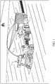
- FIG. 1 is a pictorial illustration showing one example of a self-propelled forage harvester 100 filling a tractor-pulled drain cart (or receiving vehicle) 102.
- the interior of cart 102 thus forms a receiving vessel 103 for receiving harvested material.
- a tractor 104 that is pulling grain cart 102, is positioned directly behind forage harvester 100.
- forage harvester 100 has a camera 106 mounted on the spout 108 through which the harvested material 110 is traveling. Camera 106 captures an image of the receiving area 112 of cart 102.
- harvester 100 has an automatic cart filling control system that includes image processing, as discussed above, that system can gauge the height of harvested material in cart 102, and the location of that material. It thus automatically controls the position of spout 108 and flap 109 to direct the trajectory of material 110 into the receiving area 112 of cart 102 to obtain an even fill throughout the entire length of cart 102, while not overfilling cart 102.
- image processing as discussed above
- that system can gauge the height of harvested material in cart 102, and the location of that material. It thus automatically controls the position of spout 108 and flap 109 to direct the trajectory of material 110 into the receiving area 112 of cart 102 to obtain an even fill throughout the entire length of cart 102, while not overfilling cart 102.
- automatically it is meant, for example, that the operation is performed without further human involvement except, perhaps, to initiate or authorize the operation.
- camera 106 is a stereo camera.
- the images captured by camera 106 can be used to determine how far receiving vehicle 102 is behind harvester 100. This can be used (as discussed below) to determine when receiving vehicle 102 is too far behind harvester 100 so it no longer receives the harvested material.
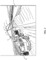
- FIG. 2 is a pictorial illustration showing another example of a self-propelled forage harvester 100, this time loading a semi-trailer (or receiving vessel on a receiving vehicle) 116 in a configuration in which a semitractor is pulling semi-trailer 116 alongside forage harvester 100. Therefore, the spout 108 and flap 109 are positioned to unload the harvested material 110 to fill trailer 116 according to a pre-defined side-by-side fill strategy.
- FIG. 2 shows that camera 106 can capture an image of semi-trailer 116. In the example illustrated in FIG. 2 , the field of view of camera 106 is directed toward the receiving area of trailer 116 so that image processing can be performed to identify the distance between harvester 100 and trailer 116.
- FIG. 3 is a block diagram showing one example of harvester 100, in more detail.
- Harvester 100 illustratively includes processors or servers 130, data store 132, a set of sensors 134 (which can include stereo camera 106, LIDAR sensor 136, RADAR sensor 138, positioning system sensor 140, speed sensor 142, and other sensors 144), communication system 146, control system 148, vehicle position detection system 150, controllable subsystems 152, operator interface mechanisms 154, and it can include other items 156.
- Vehicle position detection system 150 illustratively includes image processing system 158, relative speed processing system 160, other sensor signal processing system 162, relative position change detector 164, distance condition analysis system 166, and it can include other items 168.
- Relative position change detection system 164 includes change detector 170, rate of change detector 172, and it can include other items 174.
- Distance condition analysis system 166 can include material range analyzer 176, alert condition identifier 178, output generator 180, and it can include other items 182 as well.
- controllable subsystems 152 can include a header subsystem 184, material conveyance subsystem (e.g., spout, blower, flap, etc.) 186, propulsion subsystem 188, alert subsystem 190, steering subsystem 192, and it can include other items 194.
- FIG. 3 also shows that, in one example, operator 196 can interact with operator interface mechanisms 154 in order to control and manipulate harvester 100. Therefore, operator interface mechanisms 154 can be any of a wide variety of operator interface mechanisms, such as levers, joysticks, steering wheels, pedals, linkages, buttons, a touch sensitive display screen, among other things.
- Network 196 can thus be any of a wide variety of different types of networks, such as a near field communication, wide area network, a local area network, a cellular communication network, or any of a wide variety of other networks or combinations of networks.
- stereo camera 106 can capture an image of the receiving vehicle (either the cart, or the pulling vehicle, or both) and capture stereo images that can be processed to identify a distance of the receiving vehicle from harvester 100. The same can be done with a LIDAR sensor 136 or a RADAR sensor 138.
- positioning system sensor 140 can be a GPS receiver or other positioning system that receives coordinates of the receiver 140 in a global or local coordinate system.
- Communication system 146 can be configured to communicate with receiving vehicle 102 over network 196. Thus, harvester 100 and vehicle 102 can communicate their positions and these positions can be used to determine vehicle speed, the positions of the vehicles relative to one another, and other items.
- Speed sensor 142 can be a sensor that senses the speed of rotation of an axle, or a ground-engaging element (such as a wheel), or it can be another sensor that provides an indication of ground speed of harvester 100. It will be noted that receiving vehicle 102 can also be fitted with a speed sensor so that the speed of vehicle 102 can be communicated (using communication system 146) to harvester 100. Harvester 100 can of course have a wide variety of other sensors 144 as well.
- Vehicle position detection system 150 detects the relative positions of harvester 100 and receiving vehicle 102, with respect to one another. Thus, it can be determined whether receiving vehicle 102 is in a compromised position in which it is too far behind harvester 100 or is falling behind, and out of position for receiving harvested material from harvester 100. As discussed above, this can happen relatively rapidly, based on unexpected rapid decelerations of vehicle 102 or accelerations of harvester 100, based on unexpected stoppages of receiving vehicle 102, or for a wide variety of other reasons. Vehicle position detection system 150 provides an output to control system 148 indicative of the relative positions of harvester 100 and vehicle 102.
- control system 148 When those positions indicate that action should be taken, control system 148 generates control signals to control one or more of the controllable subsystems 152. For instance, when vehicle position detection system 150 determines that receiving vehicle 102 is too far behind, and out of position relative to harvester 100, or is quickly falling behind harvester 100 so that it will soon be out of position, then it can provide an indication of this to control system 148.
- Control system 148 can provide a control signal to control the propulsion subsystem 188 of harvester 100 to slow down or stop harvester 100, until receiving vehicle 102 again attains the proper following position.
- Control system 148 can generate a control signal to control alert subsystem 190 to surface an alert on operator interface mechanisms 154 for operator 196.
- Control system 148 can generate a control signal to control material conveyance subsystem 186 to control the blower, spout or flap position, etc.
- Control system 148 can also generate control signals to control the header subsystem 184, the steering subsystem 192 or other controllable subsystems 194.
- control system 148 can generate control signals to control multiple controllable subsystems 152. For instance, if receiving vehicle 102 is falling behind, control system 148 can generate a control signal to control propulsion subsystem 188 to stop harvester 100. It can also generate control signals to control header subsystem 184 to stop operation, and to control material conveyance subsystem 186 to stop the blower from delivering harvested material. These are just some examples of how control system 148 can generate control signals to control the various controllable subsystems 152 on harvester 100, based upon an output from vehicle position detection system 150 that the receiving vehicle is in a compromised position (e.g., it is out of position or is quickly falling out of position).
- vehicle position detection system 150 may vary, based upon the particular sensors 134 that it uses to identify the relative positions of harvester 100 and receiving vehicle 102. For instance, when stereo camera images from stereo camera 106 are used to determine those positions, then image processing system 158 is used to identify the distance between the two vehicles based upon the stereo camera images received. When speed signals are received (such as a speed signal from speed sensor 142 and a speed signal from receiving vehicle 102, or a speed derived from positioning system sensor 140 and a similar sensor on receiving vehicle 102), then relative speed processing system 160 can analyze the speed signals to determine whether receiving vehicle 102 is falling out of position.
- speed signals such as a speed signal from speed sensor 142 and a speed signal from receiving vehicle 102, or a speed derived from positioning system sensor 140 and a similar sensor on receiving vehicle 102
- relative speed processing system 160 can identify this as a situation where receiving vehicle 102 may be falling out of position.
- System 162 can process those signals. System 162 can identify a situation in which receiving vehicle 102 is out of position, or is about to be out of position.
- Relative position change detection system 164 can then identify characteristics of the change in the relative position of the two vehicles. For instance, based upon the change in speed and the duration of that change in speed, or based upon the changes in relative position obtained by image processing system 158, or based upon the other variables that can be provided to system 150 and that indicate the relative distance between the two vehicles 100 and 102, change detector 170 can detect whether that relative position has changed. Rate of change detector 172 determines the rate of change. For instance, if the change in position is relatively small, and has happened relatively slowly, then this may indicate a momentary, and reasonable, change in position. However, if the magnitude of the change in distance is relatively high, and it happened relatively quickly, then this may indicate that receiving vehicle 102 will quickly be out of position to receive the harvested material from harvester 100.
- Distance condition analysis system 166 analyzes the position of the two vehicles relative to one another, and how that position has changed, to determine whether some action needs to be taken by control system 148. In one example, distance condition analysis system 166 receives the relative position of the two vehicles, relative to one another, and determines whether vehicle 102 is out of position. If so, output generator 180 generates an output to control system 148 indicating that receiving vehicle 102 is out of position. In that case, control system 148 can generate control signals to control the controllable subsystems 152 as described above.
- distance condition analysis system 166 can consider the range of material conveyance subsystem 186 (e.g., how far subsystem 186 can blow the harvested material). For instance, if vehicle 102 has recently dropped further behind harvester 100, but the distance between the two vehicles is still acceptable, because the trajectory of the material can be changed, so that the receiving vessel on the receiving vehicle 102 is still within range of the conveyance subsystem 186, then material range analyzer 176 can identify this. Conversely, if vehicle 102 is out of range of the material conveyance subsystem 186, or is soon to be out of range (e.g., vehicle 102 is in a compromised position), then analyzer 176 can identify this as well.
- range of material conveyance subsystem 186 e.g., how far subsystem 186 can blow the harvested material. For instance, if vehicle 102 has recently dropped further behind harvester 100, but the distance between the two vehicles is still acceptable, because the trajectory of the material can be changed, so that the receiving vessel on the receiving vehicle 102 is still within range of the conveyance subsystem
- Alert condition identifier 178 can identify whether the current distance between the vehicles, and/or the characteristics of the distance between the two vehicles (e.g., whether it is steady, changing rapidly, etc.) corresponds to any of a given number of different alert conditions. For instance, if the two vehicles are within range of one another, and the distance between them is not changing significantly, then alert condition identifier 178 may identify that there is no alert condition present. However, if the two vehicles are still within range of one another, but the distance between them is changing relatively rapidly, then alert condition identifier 178 may identify an alert condition that indicates that the current distance is acceptable, but that the vehicles are quickly diverging so that vehicle 102 may quickly become out of range. If the two vehicles are already out of range of one another, then alert condition identifier 178 may identify this as a higher level of alert that requires more immediate action.
- alert condition identifier 178 may identify this as a higher level of alert that requires more immediate action.
- output generator 180 can generate a corresponding output to control system 148.
- Control system 148 can then generate the appropriate control signals to control controllable subsystems 152, based on the alert level or alter condition.
- FIG. 4 is a flow diagram illustrating one example of the operation of harvester 100 in identifying the relative positions of harvester 100 and receiving vehicle 102, and controlling harvester 100 based upon that relative distance. It is first assumed that harvester 100 is unloading material into a receiving vehicle 102. This is indicated by block 200 in the flow diagram of FIG. 4 . Receiving vehicle 102 may be in a rear unloading position, in which it is traveling substantially directly behind harvester 100. This is indicated by block 202. Receiving vehicle 102 may be in a side-by-side unloading position as well. This is indicated by block 204.
- Vehicle position detection system 150 then detects a characteristic of the position of the receiving vehicle 102 relative to the harvester 100. This is indicated by block 206. As discussed above, system 150 can use one of its components, and an input from one or more of sensors 134, to identify the raw distance between the two vehicles. This is indicated by block 208. Relative position change detection system 164 can detect the change in distance, as well as one or more other characteristics of that change. This is indicated by block 210. The characteristic of the position of the two vehicles relative to one another can be based on an analysis of an input from stereo camera 106. It can be based on an input from other non-contact sensors, such as LIDAR 136, RADAR 138, or other sensors 144. This is indicated by block 212 in the flow diagram of FIG.
- the characteristic of the position of the two vehicles relative to one another can be generated based upon inputs from positioning system sensor 140 and a similar input from receiving vehicle 102. This is indicated by block 214 in the flow diagram of FIG. 4 .
- the characteristic of the position of the two vehicles relative to one another can be determined based on inputs from speed sensor 142 (and possibly an input from a speed sensor on receiving vehicle 102).
- the characteristic of the distance can be detected in other ways as well, and this is indicated by block 216 in the flow diagram of FIG. 4 .
- Vehicle position detection system 150 then detects whether receiving vehicle 102 is in a compromised position in which it is no longer receiving the harvested material, or will soon be in a position that it no longer receives the harvested material (e.g., a position in which the proper conveyance of harvested material to receiving vehicle 102 is compromised). If the raw distance 208 between the two vehicles is sensed, then distance condition analysis system 166 can determine whether receiving vehicle 102 is out of position (e.g., out of range of the material being transferred from harvester 100). This is indicated by block 218 in the flow diagram of FIG. 4 . If so, then output generator 180 generates an output indicative of this to control system 148 and control system 148 generates one or more control signals based on that output.
- control system 148 controls alert subsystem 190 to generate an alert on operator interface mechanisms 154 for operator 196. This is indicated by block 222.
- the alert can be any type of audio, visual or haptic output that alerts operator 196 to the fact that receiving vehicle 102 is out of range, or out of position.
- Control system 148 can also generate a control signal to control one or more of controllable subsystems 152 to automatically control harvester 100 to take action based upon the indication that the two vehicles are out of range of one another. For instance, control system 148 can automatically control propulsion subsystem 188 to slow down, or stop, harvester 100. This is indicated by block 224 in the flow diagram of FIG. 4 . It can control any one or more of the controllable subsystems 152 in a wide variety of other ways as well (some of which were discussed above), and this is indicated by block 226 in the flow diagram of FIG. 4 .
- distance condition analysis system 166 determines whether the relative position of the two vehicles is changing. This is indicated by block 228 in the flow diagram of FIG. 4 . Thus, the distance between the two vehicles is changing, then distance condition analysis system 166 determines whether the relative position change needs to be addressed. This is indicated by block 239. For instance, system 166 determines whether receiving vehicle 102 is in danger of becoming out of position relative to harvester 100. If so, then output generator 180 generates an output indicative of this to control system 148 which, in turn, generates control signals to control the controllable subsystems 152. Determining whether the relative position change is to be addressed is indicated by block 230 in the flow diagram of FIG. 4 .
- distance condition analysis system 166 can make this determination in a wide variety of different ways. For instance, distance condition analysis system 166 can determine whether receiving vehicle 102 is falling too far behind harvester 100, so that action should be taken to reduce the likelihood that harvested material will no longer be received by receiving vehicle 102. Determining whether the receiving vehicle is falling too far behind harvester 100 is indicated by block 232. In another example, distance condition analysis system 166 can consider the speed or rate at which the relative position of the two vehicles is changing. It can, for instance, receive an output from relative position change detector 164 indicating how quickly receiving vehicle 102 is falling behind harvester 100 (e.g., in feet per second or in other units).
- an alert condition may be generated to take action more promptly. If it is falling behind harvester 100 only by a small distance, and relatively slowly (e.g., at a rate that meets a different threshold level), then a different alert condition can be generated, and different actions can be taken, or no action may be taken, and the system simply waits to analyze how the distance is changing in the future. Considering the speed at which the relative position between the two vehicles is changing is indicated by block 234 in the flow diagram of FIG. 4 .
- Material range analyzer 176 can also analyze the changing distance between the two vehicles in view of the range over which material conveyance subsystem 186 can convey the material to the receiving vehicle 102. For instance, if the distance is changing but the distance between the two vehicles is still within an acceptable range, so that material conveyance subsystem 186 can still convey the material far enough to be received by receiving vehicle 102, then it may be that a low level alert condition is generated, simply indicating that vehicle 102 is falling behind, but that it is still within range. However, if material range analyzer 176 determines that receiving vehicle 102 is quickly falling out of range, and will soon be outside the range of the material conveyance subsystem 186, then a higher level alert may be indicated, meaning that more immediate control responses are appropriate.
- This type of vehicle position detection and control can continue until the harvesting operation is complete. This is indicated by block 240 in the flow diagram of FIG. 4 .
- processors and servers include computer processors with associated memory and timing circuitry, not separately shown. They are functional parts of the systems or devices to which they belong and are activated by, and facilitate the functionality of the other components or items in those systems.
- the user actuatable input mechanisms can be text boxes, check boxes, icons, links, drop-down menus, search boxes, etc. They can also be actuated in a wide variety of different ways. For instance, they can be actuated using a point and click device (such as a track ball or mouse). They can be actuated using hardware buttons, switches, a joystick or keyboard, thumb switches or thumb pads, etc. They can also be actuated using a virtual keyboard or other virtual actuators. In addition, where the screen on which they are displayed is a touch sensitive screen, they can be actuated using touch gestures. Also, where the device that displays them has speech recognition components, they can be actuated using speech commands.
- a number of data stores have also been discussed. It will be noted they can each be broken into multiple data stores. All can be local to the systems accessing them, all can be remote, or some can be local while others are remote. All of these configurations are contemplated herein.
- the figures show a number of blocks with functionality ascribed to each block. It will be noted that fewer blocks can be used so the functionality is performed by fewer components. Also, more blocks can be used with the functionality distributed among more components.
- systems, components and/or logic can be comprised of hardware items (such as processors and associated memory, or other processing components, some of which are described below) that perform the functions associated with those systems, components and/or logic.
- the systems, components and/or logic can be comprised of software that is loaded into a memory and is subsequently executed by a processor or server, or other computing component, as described below.
- the systems, components and/or logic can also be comprised of different combinations of hardware, software, firmware, etc., some examples of which are described below.
- FIG. 3 can be disposed on a wide variety of different devices. Some of those devices include servers, desktop computers, laptop computers, tablet computers, or other mobile devices, such as palm top computers, cell phones, smart phones, multimedia players, personal digital assistants, etc.
Landscapes
- Engineering & Computer Science (AREA)
- Life Sciences & Earth Sciences (AREA)
- Environmental Sciences (AREA)
- Chemical & Material Sciences (AREA)
- Combustion & Propulsion (AREA)
- Mechanical Engineering (AREA)
- Transportation (AREA)
- Aviation & Aerospace Engineering (AREA)
- Soil Sciences (AREA)
- Radar, Positioning & Navigation (AREA)
- Remote Sensing (AREA)
- Physics & Mathematics (AREA)
- General Physics & Mathematics (AREA)
- Automation & Control Theory (AREA)
- Control Of Position, Course, Altitude, Or Attitude Of Moving Bodies (AREA)
- Harvester Elements (AREA)
Abstract
Description
- The present description relates to harvesting machines. More specifically, the present description relates to automatically identifying whether a receiving vehicle is in the proper position relative to the harvester, and controlling the harvester accordingly.
- There are a wide variety of different types of agricultural vehicles. Some vehicles include harvesters, such as a forage harvesters, and other harvesters, that harvest grain or other crop. Such harvesters often unload into carts which may be pulled by tractors or semi-trailers as the harvesters are moving.
- By way of example, while harvesting in a field using a forage harvester, an operator attempts to control the forage harvester to maintain harvesting efficiency, during many different types of conditions. The soil conditions, crop conditions, etc., can all change. This may result in the operator changing control settings. This means that the operator needs to devote a relatively large amount of attention to controlling the forage harvester.
- At the same time, a semi-truck or tractor-pulled cart is often in position relative to the forage harvester (e.g., behind the forage harvester or alongside the forage harvester) so that the forage harvester can fill the truck or cart while moving through the field. In some current systems, this requires the operator of the forage harvester to control the position of the unloading spout and flap so that the truck or cart is filled evenly, but not overfilled. Even a momentary misalignment between the spout and the truck or cart may result in hundreds of pounds of harvested material being dumped on the ground, or elsewhere, rather than in the truck or cart.
- As discussed above, it can be very difficult for an operator to maintain high efficiency in controlling a forage harvester, and also to optimally monitor the position of the receiving vehicle. This difficulty can even be exacerbated when the receiving vehicle is located behind the forage harvester, so that the forage harvester is executing a rear unloading operation, but the difficulty also exists in side-by-side unloading scenarios.
- In order to address these issues, some automatic cart filling control systems have been developed to automate portions of the filling process. These types of systems currently provide automation for simplifying the unloading process. One such automatic fill control system uses a stereo camera on the spout of the harvester to capture an image of the harvesting vehicle. An image processing system determines dimensions of the receiving vehicle and the distribution of the crop deposited inside it. The system also detects crop height within the receiving vehicle, in order to automatically aim the spout toward empty spots and control the flap position to achieve a more even fill, while reducing spillage.
- However, some forage harvesters do not have such an automatic cart filling control system. Even where they do, there may be instantaneous changes in the position of the receiving vehicle, relative to the forage harvester, that put the receiving vehicle in a compromised position. By a compromised position it is meant that, in one example, the receiving vessel on the receiving vehicle is out of range of the harvested material, or is soon to be out of range, so that the harvested material will so no longer land (or no longer lands) on the receiving vessel. This may result from a sudden deceleration of the receiving vessel, or acceleration of the harvester. For instance, the receiving vehicle may get stuck in muddy soil, while the forage harvester keeps moving. The receiving vehicle may fall behind the forage harvester for other reasons as well.
- If this happens, and the forage harvester operator does not know it in time to take corrective action, the harvested material can sometimes impact and damage the towing vehicle (e.g., by breaking the windshield, etc.). Similarly, if the trailing vehicle falls behind for any reason, this can result in hundreds of pounds of harvested material being dumped onto the ground, rather than into the receiving vessel on the receiving vehicle.
- A sensor detects a variable indicative of a position of a receiving vehicle relative to a harvester during a harvester operation in which a material conveyance subsystem on the harvester is conveying harvested material to the receiving vehicle. If the receiving vehicle is in a compromised position in which it is out of range of the material conveyance subsystem, or is about to be out of range, then a control signal is generated that can alert the operator of the harvester, automatically control harvester speed, or perform other control operations.
- The present description thus proceeds with respect to a harvester that automatically detects when the receiving vessel is in a compromised position (so that the harvested material is no longer landing in the receiving vessel or the receiving vessel is about to be out of range of the harvested material). A control signal is generated to alert the operator and/or automatically control the harvester.
-
-
FIG. 1 is a pictorial illustration of one example of a forage harvester filling a receiving vehicle, with the receiving vehicle in a position behind the forage harvester. -
FIG. 2 is a pictorial illustration of one example of a forage harvester filling a receiving vehicle that is alongside the forage harvester. -
FIG. 3 is a block diagram of one example of a harvester. -
FIG. 4 is a flow diagram illustrating one example of the operation of the harvester illustrated in previous figures in detecting the position of a receiving vehicle, and generating a control signal based upon that position. -
FIG. 1 is a pictorial illustration showing one example of a self-propelledforage harvester 100 filling a tractor-pulled drain cart (or receiving vehicle) 102. The interior ofcart 102 thus forms a receiving vessel 103 for receiving harvested material. In the example shown inFIG. 1 , atractor 104, that is pullinggrain cart 102, is positioned directly behindforage harvester 100. Also, in the example illustrated inFIG. 1 ,forage harvester 100 has acamera 106 mounted on thespout 108 through which the harvestedmaterial 110 is traveling.Camera 106 captures an image of thereceiving area 112 ofcart 102. Whenharvester 100 has an automatic cart filling control system that includes image processing, as discussed above, that system can gauge the height of harvested material incart 102, and the location of that material. It thus automatically controls the position ofspout 108 and flap 109 to direct the trajectory ofmaterial 110 into thereceiving area 112 ofcart 102 to obtain an even fill throughout the entire length ofcart 102, while not overfillingcart 102. By automatically it is meant, for example, that the operation is performed without further human involvement except, perhaps, to initiate or authorize the operation. - In one example, regardless of whether
harvester 100 has an automatic cart filling control system,camera 106 is a stereo camera. Thus, the images captured bycamera 106 can be used to determine how far receivingvehicle 102 is behindharvester 100. This can be used (as discussed below) to determine when receivingvehicle 102 is too far behindharvester 100 so it no longer receives the harvested material. -
FIG. 2 is a pictorial illustration showing another example of a self-propelledforage harvester 100, this time loading a semi-trailer (or receiving vessel on a receiving vehicle) 116 in a configuration in which a semitractor is pullingsemi-trailer 116 alongsideforage harvester 100. Therefore, thespout 108 and flap 109 are positioned to unload the harvestedmaterial 110 to filltrailer 116 according to a pre-defined side-by-side fill strategy. Again,FIG. 2 shows thatcamera 106 can capture an image ofsemi-trailer 116. In the example illustrated inFIG. 2 , the field of view ofcamera 106 is directed toward the receiving area oftrailer 116 so that image processing can be performed to identify the distance betweenharvester 100 andtrailer 116. -
FIG. 3 is a block diagram showing one example ofharvester 100, in more detail. Harvester 100 illustratively includes processors orservers 130,data store 132, a set of sensors 134 (which can includestereo camera 106, LIDARsensor 136, RADARsensor 138, positioning system sensor 140,speed sensor 142, and other sensors 144),communication system 146,control system 148, vehicleposition detection system 150,controllable subsystems 152,operator interface mechanisms 154, and it can includeother items 156. Vehicleposition detection system 150 illustratively includesimage processing system 158, relativespeed processing system 160, other sensorsignal processing system 162, relativeposition change detector 164, distancecondition analysis system 166, and it can includeother items 168. Relative positionchange detection system 164 includeschange detector 170, rate ofchange detector 172, and it can includeother items 174. Distancecondition analysis system 166 can includematerial range analyzer 176,alert condition identifier 178,output generator 180, and it can includeother items 182 as well.controllable subsystems 152 can include aheader subsystem 184, material conveyance subsystem (e.g., spout, blower, flap, etc.) 186,propulsion subsystem 188,alert subsystem 190,steering subsystem 192, and it can includeother items 194. -
FIG. 3 also shows that, in one example,operator 196 can interact withoperator interface mechanisms 154 in order to control and manipulateharvester 100. Therefore,operator interface mechanisms 154 can be any of a wide variety of operator interface mechanisms, such as levers, joysticks, steering wheels, pedals, linkages, buttons, a touch sensitive display screen, among other things. - In addition, receiving
vehicle 102, and otherremote systems 104 can communicate withharvester 100 overnetwork 196.Network 196 can thus be any of a wide variety of different types of networks, such as a near field communication, wide area network, a local area network, a cellular communication network, or any of a wide variety of other networks or combinations of networks. - Before describing the overall operation of
harvester 100, a brief description of some of the items inharvester 100, and their operation, will first be provided. - As discussed above,
stereo camera 106 can capture an image of the receiving vehicle (either the cart, or the pulling vehicle, or both) and capture stereo images that can be processed to identify a distance of the receiving vehicle fromharvester 100. The same can be done with aLIDAR sensor 136 or aRADAR sensor 138. In addition, positioning system sensor 140 can be a GPS receiver or other positioning system that receives coordinates of the receiver 140 in a global or local coordinate system.Communication system 146 can be configured to communicate with receivingvehicle 102 overnetwork 196. Thus,harvester 100 andvehicle 102 can communicate their positions and these positions can be used to determine vehicle speed, the positions of the vehicles relative to one another, and other items. -
Speed sensor 142 can be a sensor that senses the speed of rotation of an axle, or a ground-engaging element (such as a wheel), or it can be another sensor that provides an indication of ground speed ofharvester 100. It will be noted that receivingvehicle 102 can also be fitted with a speed sensor so that the speed ofvehicle 102 can be communicated (using communication system 146) toharvester 100.Harvester 100 can of course have a wide variety ofother sensors 144 as well. - Vehicle
position detection system 150 detects the relative positions ofharvester 100 and receivingvehicle 102, with respect to one another. Thus, it can be determined whether receivingvehicle 102 is in a compromised position in which it is too far behindharvester 100 or is falling behind, and out of position for receiving harvested material fromharvester 100. As discussed above, this can happen relatively rapidly, based on unexpected rapid decelerations ofvehicle 102 or accelerations ofharvester 100, based on unexpected stoppages of receivingvehicle 102, or for a wide variety of other reasons. Vehicleposition detection system 150 provides an output to controlsystem 148 indicative of the relative positions ofharvester 100 andvehicle 102. - When those positions indicate that action should be taken,
control system 148 generates control signals to control one or more of thecontrollable subsystems 152. For instance, when vehicleposition detection system 150 determines that receivingvehicle 102 is too far behind, and out of position relative toharvester 100, or is quickly falling behindharvester 100 so that it will soon be out of position, then it can provide an indication of this to controlsystem 148. -
Control system 148 can provide a control signal to control thepropulsion subsystem 188 ofharvester 100 to slow down or stopharvester 100, until receivingvehicle 102 again attains the proper following position.Control system 148 can generate a control signal to controlalert subsystem 190 to surface an alert onoperator interface mechanisms 154 foroperator 196.Control system 148 can generate a control signal to controlmaterial conveyance subsystem 186 to control the blower, spout or flap position, etc.Control system 148 can also generate control signals to control theheader subsystem 184, thesteering subsystem 192 or othercontrollable subsystems 194. - In addition,
control system 148 can generate control signals to control multiplecontrollable subsystems 152. For instance, if receivingvehicle 102 is falling behind,control system 148 can generate a control signal to controlpropulsion subsystem 188 to stopharvester 100. It can also generate control signals to controlheader subsystem 184 to stop operation, and to controlmaterial conveyance subsystem 186 to stop the blower from delivering harvested material. These are just some examples of howcontrol system 148 can generate control signals to control the variouscontrollable subsystems 152 onharvester 100, based upon an output from vehicleposition detection system 150 that the receiving vehicle is in a compromised position (e.g., it is out of position or is quickly falling out of position). - The particular configuration of vehicle
position detection system 150 may vary, based upon theparticular sensors 134 that it uses to identify the relative positions ofharvester 100 and receivingvehicle 102. For instance, when stereo camera images fromstereo camera 106 are used to determine those positions, thenimage processing system 158 is used to identify the distance between the two vehicles based upon the stereo camera images received. When speed signals are received (such as a speed signal fromspeed sensor 142 and a speed signal from receivingvehicle 102, or a speed derived from positioning system sensor 140 and a similar sensor on receiving vehicle 102), then relativespeed processing system 160 can analyze the speed signals to determine whether receivingvehicle 102 is falling out of position. For instance, if the speed ofharvester 100 has unexpectedly accelerated relative to the speed of receivingvehicle 102, or if the speed of receivingvehicle 102 has unexpectedly decelerated relative to the speed ofharvester 100, then relativespeed processing system 160 can identify this as a situation where receivingvehicle 102 may be falling out of position. - If other sensors (such as
LIDAR sensor 136,RADAR sensor 138, or other sensors 144) are used to identify the relative positions of the two vehicles, then othersignal processing system 162 can process those signals.System 162 can identify a situation in which receivingvehicle 102 is out of position, or is about to be out of position. - Relative position
change detection system 164 can then identify characteristics of the change in the relative position of the two vehicles. For instance, based upon the change in speed and the duration of that change in speed, or based upon the changes in relative position obtained byimage processing system 158, or based upon the other variables that can be provided tosystem 150 and that indicate the relative distance between the twovehicles change detector 170 can detect whether that relative position has changed. Rate ofchange detector 172 determines the rate of change. For instance, if the change in position is relatively small, and has happened relatively slowly, then this may indicate a momentary, and reasonable, change in position. However, if the magnitude of the change in distance is relatively high, and it happened relatively quickly, then this may indicate that receivingvehicle 102 will quickly be out of position to receive the harvested material fromharvester 100. - Distance
condition analysis system 166 analyzes the position of the two vehicles relative to one another, and how that position has changed, to determine whether some action needs to be taken bycontrol system 148. In one example, distancecondition analysis system 166 receives the relative position of the two vehicles, relative to one another, and determines whethervehicle 102 is out of position. If so,output generator 180 generates an output to controlsystem 148 indicating that receivingvehicle 102 is out of position. In that case,control system 148 can generate control signals to control thecontrollable subsystems 152 as described above. - In another example, distance
condition analysis system 166 can consider the range of material conveyance subsystem 186 (e.g., how far subsystem 186 can blow the harvested material). For instance, ifvehicle 102 has recently dropped further behindharvester 100, but the distance between the two vehicles is still acceptable, because the trajectory of the material can be changed, so that the receiving vessel on the receivingvehicle 102 is still within range of theconveyance subsystem 186, thenmaterial range analyzer 176 can identify this. Conversely, ifvehicle 102 is out of range of thematerial conveyance subsystem 186, or is soon to be out of range (e.g.,vehicle 102 is in a compromised position), then analyzer 176 can identify this as well. -
Alert condition identifier 178 can identify whether the current distance between the vehicles, and/or the characteristics of the distance between the two vehicles (e.g., whether it is steady, changing rapidly, etc.) corresponds to any of a given number of different alert conditions. For instance, if the two vehicles are within range of one another, and the distance between them is not changing significantly, then alertcondition identifier 178 may identify that there is no alert condition present. However, if the two vehicles are still within range of one another, but the distance between them is changing relatively rapidly, then alertcondition identifier 178 may identify an alert condition that indicates that the current distance is acceptable, but that the vehicles are quickly diverging so thatvehicle 102 may quickly become out of range. If the two vehicles are already out of range of one another, then alertcondition identifier 178 may identify this as a higher level of alert that requires more immediate action. - Based upon the type of alert condition,
output generator 180 can generate a corresponding output to controlsystem 148.Control system 148 can then generate the appropriate control signals to controlcontrollable subsystems 152, based on the alert level or alter condition. -
FIG. 4 is a flow diagram illustrating one example of the operation ofharvester 100 in identifying the relative positions ofharvester 100 and receivingvehicle 102, and controllingharvester 100 based upon that relative distance. It is first assumed thatharvester 100 is unloading material into a receivingvehicle 102. This is indicated byblock 200 in the flow diagram ofFIG. 4 . Receivingvehicle 102 may be in a rear unloading position, in which it is traveling substantially directly behindharvester 100. This is indicated byblock 202. Receivingvehicle 102 may be in a side-by-side unloading position as well. This is indicated by block 204. - Vehicle
position detection system 150 then detects a characteristic of the position of the receivingvehicle 102 relative to theharvester 100. This is indicated by block 206. As discussed above,system 150 can use one of its components, and an input from one or more ofsensors 134, to identify the raw distance between the two vehicles. This is indicated byblock 208. Relative positionchange detection system 164 can detect the change in distance, as well as one or more other characteristics of that change. This is indicated byblock 210. The characteristic of the position of the two vehicles relative to one another can be based on an analysis of an input fromstereo camera 106. It can be based on an input from other non-contact sensors, such asLIDAR 136,RADAR 138, orother sensors 144. This is indicated by block 212 in the flow diagram ofFIG. 4 . The characteristic of the position of the two vehicles relative to one another can be generated based upon inputs from positioning system sensor 140 and a similar input from receivingvehicle 102. This is indicated byblock 214 in the flow diagram ofFIG. 4 . The characteristic of the position of the two vehicles relative to one another can be determined based on inputs from speed sensor 142 (and possibly an input from a speed sensor on receiving vehicle 102). The characteristic of the distance can be detected in other ways as well, and this is indicated byblock 216 in the flow diagram ofFIG. 4 . - Vehicle
position detection system 150 then detects whether receivingvehicle 102 is in a compromised position in which it is no longer receiving the harvested material, or will soon be in a position that it no longer receives the harvested material (e.g., a position in which the proper conveyance of harvested material to receivingvehicle 102 is compromised). If theraw distance 208 between the two vehicles is sensed, then distancecondition analysis system 166 can determine whether receivingvehicle 102 is out of position (e.g., out of range of the material being transferred from harvester 100). This is indicated byblock 218 in the flow diagram ofFIG. 4 . If so, thenoutput generator 180 generates an output indicative of this to controlsystem 148 andcontrol system 148 generates one or more control signals based on that output. - Generating control signals is generated by
block 220 in the flow diagram ofFIG. 4 . In one example,control system 148 controlsalert subsystem 190 to generate an alert onoperator interface mechanisms 154 foroperator 196. This is indicated byblock 222. The alert can be any type of audio, visual or haptic output that alertsoperator 196 to the fact that receivingvehicle 102 is out of range, or out of position.Control system 148 can also generate a control signal to control one or more ofcontrollable subsystems 152 to automatically controlharvester 100 to take action based upon the indication that the two vehicles are out of range of one another. For instance,control system 148 can automatically controlpropulsion subsystem 188 to slow down, or stop,harvester 100. This is indicated by block 224 in the flow diagram ofFIG. 4 . It can control any one or more of thecontrollable subsystems 152 in a wide variety of other ways as well (some of which were discussed above), and this is indicated byblock 226 in the flow diagram ofFIG. 4 . - If, at
block 218, distancecondition analysis system 166 determines that receivingvehicle 102 is not yet out of range, thensystem 166 determines whether the relative position of the two vehicles is changing. This is indicated byblock 228 in the flow diagram ofFIG. 4 . Thus, the distance between the two vehicles is changing, then distancecondition analysis system 166 determines whether the relative position change needs to be addressed. This is indicated byblock 239. For instance,system 166 determines whether receivingvehicle 102 is in danger of becoming out of position relative toharvester 100. If so, thenoutput generator 180 generates an output indicative of this to controlsystem 148 which, in turn, generates control signals to control thecontrollable subsystems 152. Determining whether the relative position change is to be addressed is indicated byblock 230 in the flow diagram ofFIG. 4 . - As discussed above, distance
condition analysis system 166 can make this determination in a wide variety of different ways. For instance, distancecondition analysis system 166 can determine whether receivingvehicle 102 is falling too far behindharvester 100, so that action should be taken to reduce the likelihood that harvested material will no longer be received by receivingvehicle 102. Determining whether the receiving vehicle is falling too far behindharvester 100 is indicated by block 232. In another example, distancecondition analysis system 166 can consider the speed or rate at which the relative position of the two vehicles is changing. It can, for instance, receive an output from relativeposition change detector 164 indicating how quickly receivingvehicle 102 is falling behind harvester 100 (e.g., in feet per second or in other units). If it is falling behindharvester 100 relatively quickly (e.g., at a rate that meets a threshold level), then an alert condition may be generated to take action more promptly. If it is falling behindharvester 100 only by a small distance, and relatively slowly (e.g., at a rate that meets a different threshold level), then a different alert condition can be generated, and different actions can be taken, or no action may be taken, and the system simply waits to analyze how the distance is changing in the future. Considering the speed at which the relative position between the two vehicles is changing is indicated by block 234 in the flow diagram ofFIG. 4 . -
Material range analyzer 176 can also analyze the changing distance between the two vehicles in view of the range over whichmaterial conveyance subsystem 186 can convey the material to the receivingvehicle 102. For instance, if the distance is changing but the distance between the two vehicles is still within an acceptable range, so thatmaterial conveyance subsystem 186 can still convey the material far enough to be received by receivingvehicle 102, then it may be that a low level alert condition is generated, simply indicating thatvehicle 102 is falling behind, but that it is still within range. However, ifmaterial range analyzer 176 determines that receivingvehicle 102 is quickly falling out of range, and will soon be outside the range of thematerial conveyance subsystem 186, then a higher level alert may be indicated, meaning that more immediate control responses are appropriate. Considering the range over which the material can be conveyed bymaterial conveyance subsystem 186 is indicated by block 236 in the flow diagram ofFIG. 4 . Determining whether the change in distance between the two vehicles needs to be addressed can be done by distancecondition analysis system 166 in any of a variety of other ways as well, and this is indicted byblock 238 in the flow diagram ofFIG. 4 . - This type of vehicle position detection and control can continue until the harvesting operation is complete. This is indicated by
block 240 in the flow diagram ofFIG. 4 . - The present discussion has mentioned processors and servers. In one example, the processors and servers include computer processors with associated memory and timing circuitry, not separately shown. They are functional parts of the systems or devices to which they belong and are activated by, and facilitate the functionality of the other components or items in those systems.
- Also, a number of user interface displays have been discussed. They can take a wide variety of different forms and can have a wide variety of different user actuatable input mechanisms disposed thereon. For instance, the user actuatable input mechanisms can be text boxes, check boxes, icons, links, drop-down menus, search boxes, etc. They can also be actuated in a wide variety of different ways. For instance, they can be actuated using a point and click device (such as a track ball or mouse). They can be actuated using hardware buttons, switches, a joystick or keyboard, thumb switches or thumb pads, etc. They can also be actuated using a virtual keyboard or other virtual actuators. In addition, where the screen on which they are displayed is a touch sensitive screen, they can be actuated using touch gestures. Also, where the device that displays them has speech recognition components, they can be actuated using speech commands.
- A number of data stores have also been discussed. It will be noted they can each be broken into multiple data stores. All can be local to the systems accessing them, all can be remote, or some can be local while others are remote. All of these configurations are contemplated herein.
- Also, the figures show a number of blocks with functionality ascribed to each block. It will be noted that fewer blocks can be used so the functionality is performed by fewer components. Also, more blocks can be used with the functionality distributed among more components.
- It will be noted that the above discussion has described a variety of different systems, components and/or logic. It will be appreciated that such systems, components and/or logic can be comprised of hardware items (such as processors and associated memory, or other processing components, some of which are described below) that perform the functions associated with those systems, components and/or logic. In addition, the systems, components and/or logic can be comprised of software that is loaded into a memory and is subsequently executed by a processor or server, or other computing component, as described below. The systems, components and/or logic can also be comprised of different combinations of hardware, software, firmware, etc., some examples of which are described below. These are only some examples of different structures that can be used to form the systems, components and/or logic described above. Other structures can be used as well.
- It will also be noted that the elements of
FIG. 3 , or portions of them, can be disposed on a wide variety of different devices. Some of those devices include servers, desktop computers, laptop computers, tablet computers, or other mobile devices, such as palm top computers, cell phones, smart phones, multimedia players, personal digital assistants, etc.
Claims (15)
- A harvester, comprising:a header that gathers harvested material into the harvester;a conveyance subsystem that conveys the harvested material from the harvester to a receiving vehicle during a harvesting operation;a controllable subsystem;a vehicle position detection system that detects a deceleration of the receiving vehicle relative to the harvester; anda control system that generates a control signal to control the controllable subsystem based on the detected deceleration of the receiving vehicle relative to the harvester.
- The harvester of claim 1 wherein the controllable subsystem comprises an operator interface mechanism, wherein the control system generates the control signal to surface an alert to the operator on the operator interface mechanism.
- The harvester of claim 1 wherein the controllable subsystem comprises a propulsion subsystem and wherein the vehicle position detection system is configured to detect a distance between the harvester and the receiving vehicle and further comprises a distance condition analysis system that determines whether the distance exceeds a threshold distance relative to a range of the material conveyance subsystem and wherein the control system automatically controls the propulsion subsystem of the harvester when the distance exceeds the threshold distance.
- The harvester of claim 1 and further comprising a stereo camera that captures images of the receiving vehicle, the vehicle position detection system detecting the distance between the harvester and the receiving vehicle based on the captured images.
- A computer implemented method of controlling a harvester, comprising:controlling a material conveyance subsystem to convey harvested material to a receiving vessel in a receiving vehicle, as the harvester is performing a harvesting operation;detecting a characteristic of a position of the harvester relative to a position of the receiving vehicle;determining whether the receiving vehicle is in a compromised position relative to the harvester, in which conveyance of the harvested material to the receiving vessel is compromised, based on the characteristic of the position of the harvester relative to the position of the receiving vehicle; andif the receiving vehicle is in the compromised position, then generating a control signal to control a controllable subsystem of the harvester.
- The computer implemented method of claim 5 wherein detecting a characteristic of the position of the harvester relative to the receiving vehicle comprises determining whether the receiving vehicle is out of range of the material conveyance subsystem so the material conveyance subsystem is not conveying the harvested material to the receiving vessel of the receiving vehicle, and wherein determining whether the receiving vehicle is in a compromised position comprises if the characteristic of the position of the harvester relative to the position of the receiving vehicle indicates that the receiving vehicle is out of range of the material conveyance subsystem, then determining that the receiving vehicle is in the compromised position.
- The computer implemented method of claim 5 wherein determining whether the receiving vehicle is in a compromised position comprises:determining whether the receiving vehicle is likely to be out of range of the material conveyance subsystem within a time threshold; andif so, determining that the receiving vehicle is in the compromised position.
- The computer implemented method of claim 7 wherein detecting a characteristic of the harvester relative to the receiving vehicle comprises:detecting whether a relative speed has changed, the relative speed comprising a measure of a speed of the receiving vehicle compared to a speed of the harvester; andgenerating a speed change indicator indicative of a detected change in the relative speed.
- The computer implemented method of claim 8 wherein detecting a characteristic of the position of the harvester relative to the receiving vehicle comprises:identifying an amount by which the relative speed has changed; andgenerating a speed change magnitude signal indicative of the amount of the change in the relative speed.
- The computer implemented method of claim 1 wherein detecting a characteristic of the position of the harvester relative to the receiving vehicle comprises:detecting a rate of change of the relative speed; andgenerating a rate of change signal indicative of the detected rate of change.
- The computer implemented method of claim 10 wherein determining whether the receiving vehicle is likely to be out of range of the material conveyance subsystem within a time threshold comprises: determining whether the receiving vehicle is likely to be out of range of the material conveyance subsystem based on the speed change magnitude signal, the rate of change signal and the range of the material conveyance subsystem.
- The computer implemented method of claim 5 wherein detecting a characteristic of a position of the harvester relative to a position of the receiving vehicle comprises:receiving a set of images from a stereo camera;processing the set of stereo images to detect a distance between the harvester and the receiving vehicle; andoutputting a characteristic signal indicative of the detected distance.
- The computer implemented method of claim 5 wherein detecting a characteristic of a position of the harvester relative to a position of the receiving vehicle comprises:receiving a receiving vehicle speed signal indicative of a speed of the receiving vehicle;receiving a harvester speed signal indicative of harvester speed; andgenerating a speed difference signal indicative of a difference between the speed of the receiving vehicle and the harvester speed.
- The computer implemented method of claim 5 wherein detecting a characteristic of a position of the harvester relative to a position of the receiving vehicle comprises:receiving a receiving vehicle position signal, indicative of a position of the receiving vehicle in a coordinate system, from a positioning system on the receiving vehicle;receiving a harvester position signal, indicative of a position of the harvester in the coordinate system, from a positioning system on the harvester;detecting a distance between the harvester and the receiving vehicle based on the receiving vehicle position signal and the harvester position signal; andoutputting a characteristic signal indicative of the detected distance.
- The computer implemented method of claim 5 wherein generating a control signal comprises:identifying an alert level based on the position of the receiving vehicle relative to the compromised position; identifying a control action is to be performed based on the alert level; and generating the control signal based on the identified control action;and/or generating the control signal to control an alert system to surface an alert to an operator of the harvester;and/or generating a control signal to automatically control a harvester propulsion subsystem;and/or generating a control signal to automatically control the material conveyance subsystem.
Applications Claiming Priority (1)
| Application Number | Priority Date | Filing Date | Title |
|---|---|---|---|
| US16/865,467 US11390263B2 (en) | 2020-05-04 | 2020-05-04 | Forage harvester with automatic detection of receiving vehicle |
Publications (2)
| Publication Number | Publication Date |
|---|---|
| EP3906765A1 true EP3906765A1 (en) | 2021-11-10 |
| EP3906765B1 EP3906765B1 (en) | 2024-11-27 |
Family
ID=75562681
Family Applications (1)
| Application Number | Title | Priority Date | Filing Date |
|---|---|---|---|
| EP21168958.3A Active EP3906765B1 (en) | 2020-05-04 | 2021-04-16 | Forage harvester with automatic detection of receiving vehicle |
Country Status (2)
| Country | Link |
|---|---|
| US (1) | US11390263B2 (en) |
| EP (1) | EP3906765B1 (en) |
Families Citing this family (13)
| Publication number | Priority date | Publication date | Assignee | Title |
|---|---|---|---|---|
| US11950538B2 (en) * | 2020-05-19 | 2024-04-09 | Deere & Company | Commodity cart with improved loading positioning |
| GB202011034D0 (en) * | 2020-07-17 | 2020-09-02 | Agco Int Gmbh | System and method of assisted or automated grain unload synchronization |
| US12135571B2 (en) | 2021-04-06 | 2024-11-05 | Deere & Company | Control system for controlling filling based on load weight |
| GB202114576D0 (en) * | 2021-10-12 | 2021-11-24 | Agco Int Gmbh | Harvester systems and methods for automated and semi-automated filling of groups of receiving vehicles |
| US12082531B2 (en) | 2022-01-26 | 2024-09-10 | Deere & Company | Systems and methods for predicting material dynamics |
| US12520759B2 (en) | 2022-01-26 | 2026-01-13 | Deere & Company | Systems and methods for predicting material dynamics |
| US12298767B2 (en) | 2022-04-08 | 2025-05-13 | Deere & Company | Predictive material consumption map and control |
| US12604791B2 (en) | 2022-07-06 | 2026-04-21 | Deere & Company | Machine control based upon estimated operator skill level trend |
| AU2022473991A1 (en) | 2022-08-11 | 2024-11-14 | Deere & Company | Systems and methods for predictive harvesting logistics |
| CA3251707A1 (en) | 2022-08-11 | 2024-02-15 | Deere & Company | Systems and methods for predictive harvesting logistics |
| US20250278099A1 (en) * | 2024-03-01 | 2025-09-04 | Deere & Company | Position-based initiation of auto unloading operation |
| WO2025234267A1 (en) * | 2024-05-08 | 2025-11-13 | 株式会社デンソー | Position-identifying system and position-identifying program |
| CN118805538B (en) * | 2024-06-06 | 2025-02-11 | 邵阳学院 | An intelligent and efficient vegetable defoliating harvester control system and method |
Citations (5)
| Publication number | Priority date | Publication date | Assignee | Title |
|---|---|---|---|---|
| EP2579701B1 (en) * | 2010-06-09 | 2015-03-04 | CNH Industrial Belgium nv | Automatic grain transfer control system based on real time modeling of a fill level for regions of the receiving container |
| US9119342B2 (en) * | 2013-04-22 | 2015-09-01 | Deere & Company, A Delaware Corporation | Methods for improving the robustness of an automated unloading system |
| US9642305B2 (en) * | 2015-08-10 | 2017-05-09 | Deere & Company | Method and stereo vision system for managing the unloading of an agricultural material from a vehicle |
| US20170147005A1 (en) * | 2015-11-19 | 2017-05-25 | Agjunction Llc | Automated multi-vehicle alignment steering |
| EP3315005A1 (en) * | 2016-10-28 | 2018-05-02 | Deere & Company | Method and stereo vision system for managing the unloading of an agricultural material from a vehicle |
Family Cites Families (26)
| Publication number | Priority date | Publication date | Assignee | Title |
|---|---|---|---|---|
| US4376609A (en) * | 1980-03-31 | 1983-03-15 | Sperry Corporation | Automatic spout control for agricultural machines |
| DE19848127A1 (en) * | 1998-10-19 | 2000-04-20 | Claas Selbstfahr Erntemasch | Device for controlling a transfer device |
| US6682416B2 (en) * | 2000-12-23 | 2004-01-27 | Claas Selbstfahrende Erntemaschinen Gmbh | Automatic adjustment of a transfer device on an agricultural harvesting machine |
| US20030063968A1 (en) * | 2001-10-01 | 2003-04-03 | Zaun Richard D. | Apparatus for transporting and filling freight containers |
| US6943824B2 (en) * | 2002-03-13 | 2005-09-13 | Deere & Company | Image processing spout control system |
| DE102007009666A1 (en) * | 2007-02-22 | 2008-08-28 | Carl Zeiss Microimaging Gmbh | Arrangement for filling a container with bulk material |
| ATE546991T1 (en) * | 2007-08-03 | 2012-03-15 | Agrocom Gmbh & Co Agrarsystem Kg | AGRICULTURAL WORKING MACHINE |
| US7677169B2 (en) * | 2007-09-06 | 2010-03-16 | Cnh America Llc | Apparatus and method using imaging in building a cotton module |
| US8180534B2 (en) * | 2008-09-18 | 2012-05-15 | Deere & Company | Multiple harvester unloading system |
| US8126620B2 (en) * | 2009-04-28 | 2012-02-28 | Cnh America Llc | Grain transfer control system and method |
| DE102009027245A1 (en) * | 2009-06-26 | 2010-12-30 | Deere & Company, Moline | Control arrangement for controlling the transfer of agricultural crop from a harvester to a transport vehicle |
| DE102011002071A1 (en) | 2011-04-15 | 2012-10-18 | Claas Selbstfahrende Erntemaschinen Gmbh | System and method for controlling crop overload |
| DE102011082052B4 (en) * | 2011-09-02 | 2015-05-28 | Deere & Company | Arrangement and method for the automatic overloading of crop material from a harvester onto a transport vehicle |
| US9861040B2 (en) * | 2012-02-10 | 2018-01-09 | Deere & Company | Method and stereo vision system for facilitating the unloading of agricultural material from a vehicle |
| US9392746B2 (en) * | 2012-02-10 | 2016-07-19 | Deere & Company | Artificial intelligence for detecting and filling void areas of agricultural commodity containers |
| AU2013216776B2 (en) * | 2012-02-10 | 2017-01-19 | Deere & Company | System and method of material handling using one or more imaging devices on the transferring vehicle and on the receiving vehicle to control the material distribution into the storage portion of the receiving vehicle |
| US9326444B2 (en) * | 2013-02-08 | 2016-05-03 | Deere & Company | Method and stereo vision system for facilitating the unloading of agricultural material from a vehicle |
| US10129528B2 (en) * | 2013-04-02 | 2018-11-13 | Deere & Company | Control arrangement and method for controlling a position of a transfer device of a harvesting machine |
| BE1021164B1 (en) | 2013-10-28 | 2016-01-18 | Cnh Industrial Belgium Nv | DISCHARGE SYSTEMS |
| DE102014100136A1 (en) | 2014-01-08 | 2015-07-09 | Claas Selbstfahrende Erntemaschinen Gmbh | harvester |
| BR102015013228B1 (en) | 2014-06-13 | 2020-11-24 | Cnh Industrial America Llc | CONTROL SYSTEM AND METHOD FOR AN AGRICULTURAL VEHICLE |
| DE102014216603B4 (en) * | 2014-08-21 | 2018-02-22 | Wirtgen Gmbh | Self-propelled milling machine, as well as method for unloading milled material |
| DE102014216763B4 (en) * | 2014-08-22 | 2018-07-26 | Wirtgen Gmbh | Self-propelled milling machine, as well as method for unloading milled material |
| US10015928B2 (en) * | 2015-08-10 | 2018-07-10 | Deere & Company | Method and stereo vision system for managing the unloading of an agricultural material from a vehicle |
| US10019790B2 (en) * | 2016-01-15 | 2018-07-10 | Deere & Company | Fill level indicator for an automated unloading system |
| US9675008B1 (en) * | 2016-02-29 | 2017-06-13 | Cnh Industrial America Llc | Unloading arrangement for agricultural harvesting vehicles |
-
2020
- 2020-05-04 US US16/865,467 patent/US11390263B2/en active Active
-
2021
- 2021-04-16 EP EP21168958.3A patent/EP3906765B1/en active Active
Patent Citations (5)
| Publication number | Priority date | Publication date | Assignee | Title |
|---|---|---|---|---|
| EP2579701B1 (en) * | 2010-06-09 | 2015-03-04 | CNH Industrial Belgium nv | Automatic grain transfer control system based on real time modeling of a fill level for regions of the receiving container |
| US9119342B2 (en) * | 2013-04-22 | 2015-09-01 | Deere & Company, A Delaware Corporation | Methods for improving the robustness of an automated unloading system |
| US9642305B2 (en) * | 2015-08-10 | 2017-05-09 | Deere & Company | Method and stereo vision system for managing the unloading of an agricultural material from a vehicle |
| US20170147005A1 (en) * | 2015-11-19 | 2017-05-25 | Agjunction Llc | Automated multi-vehicle alignment steering |
| EP3315005A1 (en) * | 2016-10-28 | 2018-05-02 | Deere & Company | Method and stereo vision system for managing the unloading of an agricultural material from a vehicle |
Also Published As
| Publication number | Publication date |
|---|---|
| US20210339729A1 (en) | 2021-11-04 |
| EP3906765B1 (en) | 2024-11-27 |
| US11390263B2 (en) | 2022-07-19 |
Similar Documents
| Publication | Publication Date | Title |
|---|---|---|
| EP3906765B1 (en) | Forage harvester with automatic detection of receiving vehicle | |
| EP3903558B1 (en) | Automatic fill control based on visual identification of grain receiving vehicles | |
| EP4070636B1 (en) | Control system for controlling filling based on load weight | |
| EP3973763B1 (en) | Automated camera system control for harvesting machine unloading | |
| EP4169368B1 (en) | System for dynamically detecting alert conditions and optimization criteria | |
| US12439853B2 (en) | Closed loop control of filling mechanisms | |
| EP4046474B1 (en) | Harvester with feed forward control of filling mechanisms | |
| EP4056019B1 (en) | Agricultural harvester with operator commanded placement for control of discharge spout | |
| EP4091426B1 (en) | Control system detecting fill level on receiving vehicles | |
| US12490678B2 (en) | Vehicle location with dynamic model and unloading control system | |
| EP4371394A2 (en) | Automatic unloading system shutoff for an unloading operation | |
| US20260053097A1 (en) | Cross member location and avoidance during an unloading operation | |
| EP4652828A1 (en) | Using a weight versus position profile to control automated unloading | |
| EP4360431A1 (en) | Performing a fill-to-weight unloading operation | |
| US20250133986A1 (en) | Material transfer status monitoring and control | |
| US20250133985A1 (en) | Material transfer subsystem extension control | |
| US20250133988A1 (en) | Material transfer subsystem retraction control | |
| EP4360419A1 (en) | Vehicle parameter offset value management and control system | |
| US12527245B2 (en) | Automated image-based receiving vehicle boundary detection and control | |
| US12504763B2 (en) | Nudge proximity indication during control of an unloading operation | |
| EP4360433B1 (en) | Harvesting machine unloading control system with automated cart parameter locator | |
| EP4717069A1 (en) | Unloading control based on identified hopper door position | |
| US20250137832A1 (en) | Scale based unload rate calculation | |
| EP4360441A1 (en) | Multi pass unloading operation |
Legal Events
| Date | Code | Title | Description |
|---|---|---|---|
| PUAI | Public reference made under article 153(3) epc to a published international application that has entered the european phase |
Free format text: ORIGINAL CODE: 0009012 |
|
| STAA | Information on the status of an ep patent application or granted ep patent |
Free format text: STATUS: THE APPLICATION HAS BEEN PUBLISHED |
|
| AK | Designated contracting states |
Kind code of ref document: A1 Designated state(s): AL AT BE BG CH CY CZ DE DK EE ES FI FR GB GR HR HU IE IS IT LI LT LU LV MC MK MT NL NO PL PT RO RS SE SI SK SM TR |
|
| B565 | Issuance of search results under rule 164(2) epc |
Effective date: 20211001 |
|
| STAA | Information on the status of an ep patent application or granted ep patent |
Free format text: STATUS: REQUEST FOR EXAMINATION WAS MADE |
|
| 17P | Request for examination filed |
Effective date: 20220510 |
|
| RBV | Designated contracting states (corrected) |
Designated state(s): AL AT BE BG CH CY CZ DE DK EE ES FI FR GB GR HR HU IE IS IT LI LT LU LV MC MK MT NL NO PL PT RO RS SE SI SK SM TR |
|
| REG | Reference to a national code |
Ref country code: DE Ref legal event code: R079 Free format text: PREVIOUS MAIN CLASS: A01B0069040000 Ref country code: DE Ref legal event code: R079 Ref document number: 602021022286 Country of ref document: DE Free format text: PREVIOUS MAIN CLASS: A01B0069040000 Ipc: G05D0001000000 |
|
| GRAP | Despatch of communication of intention to grant a patent |
Free format text: ORIGINAL CODE: EPIDOSNIGR1 |
|
| STAA | Information on the status of an ep patent application or granted ep patent |
Free format text: STATUS: GRANT OF PATENT IS INTENDED |
|
| RIC1 | Information provided on ipc code assigned before grant |
Ipc: G05D 1/00 20060101AFI20240627BHEP |
|
| INTG | Intention to grant announced |
Effective date: 20240719 |
|
| GRAS | Grant fee paid |
Free format text: ORIGINAL CODE: EPIDOSNIGR3 |
|
| GRAA | (expected) grant |
Free format text: ORIGINAL CODE: 0009210 |
|
| STAA | Information on the status of an ep patent application or granted ep patent |
Free format text: STATUS: THE PATENT HAS BEEN GRANTED |
|
| AK | Designated contracting states |
Kind code of ref document: B1 Designated state(s): AL AT BE BG CH CY CZ DE DK EE ES FI FR GB GR HR HU IE IS IT LI LT LU LV MC MK MT NL NO PL PT RO RS SE SI SK SM TR |
|
| REG | Reference to a national code |
Ref country code: GB Ref legal event code: FG4D |
|
| REG | Reference to a national code |
Ref country code: CH Ref legal event code: EP |
|
| REG | Reference to a national code |
Ref country code: IE Ref legal event code: FG4D |
|
| REG | Reference to a national code |
Ref country code: DE Ref legal event code: R096 Ref document number: 602021022286 Country of ref document: DE |
|
| REG | Reference to a national code |
Ref country code: LT Ref legal event code: MG9D |
|
| REG | Reference to a national code |
Ref country code: NL Ref legal event code: MP Effective date: 20241127 |
|
| PG25 | Lapsed in a contracting state [announced via postgrant information from national office to epo] |
Ref country code: PT Free format text: LAPSE BECAUSE OF FAILURE TO SUBMIT A TRANSLATION OF THE DESCRIPTION OR TO PAY THE FEE WITHIN THE PRESCRIBED TIME-LIMIT Effective date: 20250327 Ref country code: IS Free format text: LAPSE BECAUSE OF FAILURE TO SUBMIT A TRANSLATION OF THE DESCRIPTION OR TO PAY THE FEE WITHIN THE PRESCRIBED TIME-LIMIT Effective date: 20250327 Ref country code: HR Free format text: LAPSE BECAUSE OF FAILURE TO SUBMIT A TRANSLATION OF THE DESCRIPTION OR TO PAY THE FEE WITHIN THE PRESCRIBED TIME-LIMIT Effective date: 20241127 |
|
| PG25 | Lapsed in a contracting state [announced via postgrant information from national office to epo] |
Ref country code: FI Free format text: LAPSE BECAUSE OF FAILURE TO SUBMIT A TRANSLATION OF THE DESCRIPTION OR TO PAY THE FEE WITHIN THE PRESCRIBED TIME-LIMIT Effective date: 20241127 Ref country code: NL Free format text: LAPSE BECAUSE OF FAILURE TO SUBMIT A TRANSLATION OF THE DESCRIPTION OR TO PAY THE FEE WITHIN THE PRESCRIBED TIME-LIMIT Effective date: 20241127 |
|
| REG | Reference to a national code |
Ref country code: AT Ref legal event code: MK05 Ref document number: 1746278 Country of ref document: AT Kind code of ref document: T Effective date: 20241127 |
|
| PG25 | Lapsed in a contracting state [announced via postgrant information from national office to epo] |
Ref country code: BG Free format text: LAPSE BECAUSE OF FAILURE TO SUBMIT A TRANSLATION OF THE DESCRIPTION OR TO PAY THE FEE WITHIN THE PRESCRIBED TIME-LIMIT Effective date: 20241127 |
|
| PG25 | Lapsed in a contracting state [announced via postgrant information from national office to epo] |
Ref country code: ES Free format text: LAPSE BECAUSE OF FAILURE TO SUBMIT A TRANSLATION OF THE DESCRIPTION OR TO PAY THE FEE WITHIN THE PRESCRIBED TIME-LIMIT Effective date: 20241127 |
|
| PG25 | Lapsed in a contracting state [announced via postgrant information from national office to epo] |
Ref country code: NO Free format text: LAPSE BECAUSE OF FAILURE TO SUBMIT A TRANSLATION OF THE DESCRIPTION OR TO PAY THE FEE WITHIN THE PRESCRIBED TIME-LIMIT Effective date: 20250227 |
|
| PG25 | Lapsed in a contracting state [announced via postgrant information from national office to epo] |
Ref country code: LV Free format text: LAPSE BECAUSE OF FAILURE TO SUBMIT A TRANSLATION OF THE DESCRIPTION OR TO PAY THE FEE WITHIN THE PRESCRIBED TIME-LIMIT Effective date: 20241127 Ref country code: AT Free format text: LAPSE BECAUSE OF FAILURE TO SUBMIT A TRANSLATION OF THE DESCRIPTION OR TO PAY THE FEE WITHIN THE PRESCRIBED TIME-LIMIT Effective date: 20241127 Ref country code: GR Free format text: LAPSE BECAUSE OF FAILURE TO SUBMIT A TRANSLATION OF THE DESCRIPTION OR TO PAY THE FEE WITHIN THE PRESCRIBED TIME-LIMIT Effective date: 20250228 |
|
| PG25 | Lapsed in a contracting state [announced via postgrant information from national office to epo] |
Ref country code: PL Free format text: LAPSE BECAUSE OF FAILURE TO SUBMIT A TRANSLATION OF THE DESCRIPTION OR TO PAY THE FEE WITHIN THE PRESCRIBED TIME-LIMIT Effective date: 20241127 |
|
| PG25 | Lapsed in a contracting state [announced via postgrant information from national office to epo] |
Ref country code: RS Free format text: LAPSE BECAUSE OF FAILURE TO SUBMIT A TRANSLATION OF THE DESCRIPTION OR TO PAY THE FEE WITHIN THE PRESCRIBED TIME-LIMIT Effective date: 20250227 |
|
| PG25 | Lapsed in a contracting state [announced via postgrant information from national office to epo] |
Ref country code: SM Free format text: LAPSE BECAUSE OF FAILURE TO SUBMIT A TRANSLATION OF THE DESCRIPTION OR TO PAY THE FEE WITHIN THE PRESCRIBED TIME-LIMIT Effective date: 20241127 |
|
| PGFP | Annual fee paid to national office [announced via postgrant information from national office to epo] |
Ref country code: DE Payment date: 20250319 Year of fee payment: 5 |
|
| PG25 | Lapsed in a contracting state [announced via postgrant information from national office to epo] |
Ref country code: DK Free format text: LAPSE BECAUSE OF FAILURE TO SUBMIT A TRANSLATION OF THE DESCRIPTION OR TO PAY THE FEE WITHIN THE PRESCRIBED TIME-LIMIT Effective date: 20241127 |
|
| PGFP | Annual fee paid to national office [announced via postgrant information from national office to epo] |
Ref country code: BE Payment date: 20250428 Year of fee payment: 5 |
|
| PG25 | Lapsed in a contracting state [announced via postgrant information from national office to epo] |
Ref country code: EE Free format text: LAPSE BECAUSE OF FAILURE TO SUBMIT A TRANSLATION OF THE DESCRIPTION OR TO PAY THE FEE WITHIN THE PRESCRIBED TIME-LIMIT Effective date: 20241127 |
|
| PG25 | Lapsed in a contracting state [announced via postgrant information from national office to epo] |
Ref country code: RO Free format text: LAPSE BECAUSE OF FAILURE TO SUBMIT A TRANSLATION OF THE DESCRIPTION OR TO PAY THE FEE WITHIN THE PRESCRIBED TIME-LIMIT Effective date: 20241127 |
|
| PG25 | Lapsed in a contracting state [announced via postgrant information from national office to epo] |
Ref country code: SK Free format text: LAPSE BECAUSE OF FAILURE TO SUBMIT A TRANSLATION OF THE DESCRIPTION OR TO PAY THE FEE WITHIN THE PRESCRIBED TIME-LIMIT Effective date: 20241127 |
|
| PG25 | Lapsed in a contracting state [announced via postgrant information from national office to epo] |
Ref country code: CZ Free format text: LAPSE BECAUSE OF FAILURE TO SUBMIT A TRANSLATION OF THE DESCRIPTION OR TO PAY THE FEE WITHIN THE PRESCRIBED TIME-LIMIT Effective date: 20241127 |
|
| PG25 | Lapsed in a contracting state [announced via postgrant information from national office to epo] |
Ref country code: IT Free format text: LAPSE BECAUSE OF FAILURE TO SUBMIT A TRANSLATION OF THE DESCRIPTION OR TO PAY THE FEE WITHIN THE PRESCRIBED TIME-LIMIT Effective date: 20241127 |
|
| REG | Reference to a national code |
Ref country code: DE Ref legal event code: R097 Ref document number: 602021022286 Country of ref document: DE |
|
| PG25 | Lapsed in a contracting state [announced via postgrant information from national office to epo] |
Ref country code: SE Free format text: LAPSE BECAUSE OF FAILURE TO SUBMIT A TRANSLATION OF THE DESCRIPTION OR TO PAY THE FEE WITHIN THE PRESCRIBED TIME-LIMIT Effective date: 20241127 |
|
| PLBE | No opposition filed within time limit |
Free format text: ORIGINAL CODE: 0009261 |
|
| STAA | Information on the status of an ep patent application or granted ep patent |
Free format text: STATUS: NO OPPOSITION FILED WITHIN TIME LIMIT |
|
| REG | Reference to a national code |
Ref country code: CH Ref legal event code: L10 Free format text: ST27 STATUS EVENT CODE: U-0-0-L10-L00 (AS PROVIDED BY THE NATIONAL OFFICE) Effective date: 20251008 |
|
| 26N | No opposition filed |
Effective date: 20250828 |
|
| REG | Reference to a national code |
Ref country code: CH Ref legal event code: H13 Free format text: ST27 STATUS EVENT CODE: U-0-0-H10-H13 (AS PROVIDED BY THE NATIONAL OFFICE) Effective date: 20251125 |
|
| PG25 | Lapsed in a contracting state [announced via postgrant information from national office to epo] |
Ref country code: LU Free format text: LAPSE BECAUSE OF NON-PAYMENT OF DUE FEES Effective date: 20250416 |
|
| PG25 | Lapsed in a contracting state [announced via postgrant information from national office to epo] |
Ref country code: MC Free format text: LAPSE BECAUSE OF FAILURE TO SUBMIT A TRANSLATION OF THE DESCRIPTION OR TO PAY THE FEE WITHIN THE PRESCRIBED TIME-LIMIT Effective date: 20241127 |
|
| GBPC | Gb: european patent ceased through non-payment of renewal fee |
Effective date: 20250416 |
|
| PG25 | Lapsed in a contracting state [announced via postgrant information from national office to epo] |
Ref country code: GB Free format text: LAPSE BECAUSE OF NON-PAYMENT OF DUE FEES Effective date: 20250416 |
|
| PG25 | Lapsed in a contracting state [announced via postgrant information from national office to epo] |
Ref country code: FR Free format text: LAPSE BECAUSE OF NON-PAYMENT OF DUE FEES Effective date: 20250430 |
|
| PG25 | Lapsed in a contracting state [announced via postgrant information from national office to epo] |
Ref country code: CH Free format text: LAPSE BECAUSE OF NON-PAYMENT OF DUE FEES Effective date: 20250430 |
|
| PG25 | Lapsed in a contracting state [announced via postgrant information from national office to epo] |
Ref country code: IE Free format text: LAPSE BECAUSE OF NON-PAYMENT OF DUE FEES Effective date: 20250416 |