EP3906640B1 - Devices and method for controlling network routing configurations - Google Patents
Devices and method for controlling network routing configurations Download PDFInfo
- Publication number
- EP3906640B1 EP3906640B1 EP19704597.4A EP19704597A EP3906640B1 EP 3906640 B1 EP3906640 B1 EP 3906640B1 EP 19704597 A EP19704597 A EP 19704597A EP 3906640 B1 EP3906640 B1 EP 3906640B1
- Authority
- EP
- European Patent Office
- Prior art keywords
- cluster
- routing configuration
- traffic
- hierarchy level
- clusters
- Prior art date
- Legal status (The legal status is an assumption and is not a legal conclusion. Google has not performed a legal analysis and makes no representation as to the accuracy of the status listed.)
- Active
Links
Images



Classifications
-
- H—ELECTRICITY
- H04—ELECTRIC COMMUNICATION TECHNIQUE
- H04L—TRANSMISSION OF DIGITAL INFORMATION, e.g. TELEGRAPHIC COMMUNICATION
- H04L43/00—Arrangements for monitoring or testing data switching networks
- H04L43/04—Processing captured monitoring data, e.g. for logfile generation
-
- H—ELECTRICITY
- H04—ELECTRIC COMMUNICATION TECHNIQUE
- H04L—TRANSMISSION OF DIGITAL INFORMATION, e.g. TELEGRAPHIC COMMUNICATION
- H04L45/00—Routing or path finding of packets in data switching networks
- H04L45/02—Topology update or discovery
-
- H—ELECTRICITY
- H04—ELECTRIC COMMUNICATION TECHNIQUE
- H04L—TRANSMISSION OF DIGITAL INFORMATION, e.g. TELEGRAPHIC COMMUNICATION
- H04L45/00—Routing or path finding of packets in data switching networks
- H04L45/02—Topology update or discovery
- H04L45/04—Interdomain routing, e.g. hierarchical routing
-
- H—ELECTRICITY
- H04—ELECTRIC COMMUNICATION TECHNIQUE
- H04L—TRANSMISSION OF DIGITAL INFORMATION, e.g. TELEGRAPHIC COMMUNICATION
- H04L45/00—Routing or path finding of packets in data switching networks
- H04L45/38—Flow based routing
-
- H—ELECTRICITY
- H04—ELECTRIC COMMUNICATION TECHNIQUE
- H04L—TRANSMISSION OF DIGITAL INFORMATION, e.g. TELEGRAPHIC COMMUNICATION
- H04L45/00—Routing or path finding of packets in data switching networks
- H04L45/42—Centralised routing
-
- H—ELECTRICITY
- H04—ELECTRIC COMMUNICATION TECHNIQUE
- H04L—TRANSMISSION OF DIGITAL INFORMATION, e.g. TELEGRAPHIC COMMUNICATION
- H04L45/00—Routing or path finding of packets in data switching networks
- H04L45/46—Cluster building
-
- H—ELECTRICITY
- H04—ELECTRIC COMMUNICATION TECHNIQUE
- H04L—TRANSMISSION OF DIGITAL INFORMATION, e.g. TELEGRAPHIC COMMUNICATION
- H04L47/00—Traffic control in data switching networks
- H04L47/10—Flow control; Congestion control
- H04L47/12—Avoiding congestion; Recovering from congestion
- H04L47/125—Avoiding congestion; Recovering from congestion by balancing the load, e.g. traffic engineering
Definitions
- the present disclosure relates to the field of Traffic Engineering (TE) in a network, e.g. in a Software Defined Network (SDN).
- TE Traffic Engineering
- SDN Software Defined Network
- the disclosure is particularly concerned with routing traffic through the network.
- the disclosure relates to a device for controlling network routing configurations, and a corresponding method.
- the controlling of the network routing configurations is based on traffic matrices, which are grouped into clusters of different hierarchy level.
- TE plays a crucial role in network management, since it permits optimizing the utilization of network resources.
- SDN controllers or Path Computation Elements (PCE) integrate TE methods, in order to continuously optimize the network.
- PCE Path Computation Elements
- sudden and unpredictable changes of the network e.g. traffic variations and/or network failures, still pose a major challenge for conventional TE methods.
- the conventional TE methods which have been devised to cope with network changes, can be broadly classified into three classes: Dynamic TE, Static TE and Semi-Static TE.
- Dynamic TE reconfigures the network each time a new event, like a traffic change or link failure, occurs in the network.
- a monitoring system is typically used by Dynamic TE methods, in order to collect information over a relatively short period of time, and to predict the future evolution of the network system. For example, a certain number of past traffic matrices is used to predict the next traffic matrix. This prediction is then used as an input of the Dynamic TE methods to reconfigure the network.
- Sophisticated methods like linear programming, can be used to compute the best network configuration any time the traffic changes. However, reconfiguring the network too frequently can affect its stability, since programming hardware equipment takes time. Thus, too frequent network reconfigurations may result in worse performance.
- TE methods reducing the number of network reconfigurations have also been proposed, e.g. methods that reconfigure the network only, if the benefit of the reconfiguring, as captured by an objective function, is larger than the benefit of further using the current network configuration.
- the efficacy of Dynamic TE methods depends on the accuracy of the prediction method that is used to estimate the evolution of the system. Indeed, prediction errors can lead to large deviations of the network performance when optimized by Dynamic TE methods.
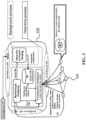
- FIG. 9 shows an example of a general architecture of a SDN controller, wherein the information collected by a monitoring system is used by a Dynamic TE mechanism, in order to predict the next status of the network system, and to accordingly compute/update a network routing configuration.
- Stable TE computes a single configuration, which provides bounded performance loss, in case of prediction errors or unpredictable events, with respect to the optimal configuration.
- One of the first techniques of Stable TE is oblivious routing, which randomly selects the paths (routes) to connect a source and destination using a small subset of preselected nodes without using any knowledge of the traffic. Routing techniques that are totally oblivious to any traffic information and system changes can provide the highest robustness against any system evolution. However, the performance loss can quickly become large as the network size increases. For this reason, a partial knowledge of the traffic can also be integrated in the computation of the network configuration to improve oblivious routing.
- Some Stable TE methods compute a network configuration with performance guarantees for any traffic matrix (TM) that belongs to a bounded domain/set obtained using the information collected by the monitoring system.
- Other methods introduce different models for traffic uncertainness, e.g. by expressing the maximum load that can be expected over a link (pipe model) or an upper bound on the traffic emanating from a source node and directed to a destination node (hose model). Based on those models a network configuration with performance guarantees is computed.
- these uncertainness models include less information than the multiple TM approach, thus providing larger performance losses.
- some methods consider only the most likely TMs for building the bounded set and computing of the optimal configuration. A penalty term is added in the optimization for less probable TMs. While such a method provides a good solution when the traffic varies smoothly, it cannot guarantee a feasible configuration against unexpected or unlikely events, since they are excluded from the computation.
- Semi-Static TE methods provide a limited set of routing configurations. This allows, on the one hand, to not reconfigure the network as frequently as in Dynamic TE. On the other hand, it also limits the robustness of each single routing configuration, thus reducing the performance loss.
- Some approaches divide the TM polytope in few subsets according to some dimensions, and compute a robust routing for each subset. While representing an initial attempt to split the TM domain in multiple parts, these approaches present several limitations: slicing directions are arbitrary; the number of created subsets is limited; and the partition is performed either in the traffic domain or in the time domain. Therefore, they can achieve only a limited performance improvement compared to the whole set of TM-space splitting possibilities.
- break-before-make which consists in stopping the communication between source and destination, waiting for all packets on route to arrive at their destination, removing the relevant entries from the routing tables of the routers along the current route, establishing the new route by instructing the routers along the new route to have an entry for the connection, and at last, resuming the communication.
- WO 2018/219420 A1 discloses a system and method for providing a routing configuration built according to monitored traffic matrices and predicted traffic matrices.
- embodiments of the present invention aim to provide an improved approach to TE.
- the invention aims for an improved control of network routing configurations over time.
- An objective is to allow for a smoother updating/changing of network routing configurations, particularly in case of sudden and unpredictable changes of the network.
- the approach of the invention should be usable together with Dynamic TE, Static TE or Semi-static TE methods.
- the updating/changing of the network routing configurations should include the smooth updating of routes (paths) of one routing configuration to the routes of another routing configuration.
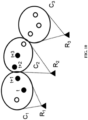
- FIG. 10 shows a scenario, in which three Stable TE network routing configurations (R1, R2, and R3, each associated with a cluster C1, C2 and C3 of traffic matrices) are successively applied in all network equipments (e.g. switches).
- the main issue in such a scenario is that an abrupt network routing configuration change (e.g. from R1 to R2, or R2 to R3) can lead to packet losses, and "make-before break" approaches may not be always applicable without dead locks (i.e. without packet losses).
- the embodiments of the invention base on the proposal to build a hierarchy of clusters of traffic matrices, which are each associated with a routing configuration. That is, effectively a hierarchy of routing configurations is built. This enables pre-fetching a parent routing configuration (higher hierarchy level) and then removing it in the transition between two child routing configurations (lower hierarchy level), in order to smoothly update the network from one child routing configuration to the other. Thereby, load balancing weights may also be used, in order to progressively move the traffic in the evolving set of routes of the respective routing configurations.
- a first aspect of the invention provides a device for controlling network routing configurations in a network according to claim 1.
- a corresponding method is defined by claim 9. Further embodiments are defined by the dependent claims.
- a cluster is/includes a set of TMs.
- the plurality of traffic matrices may be, or may be based on, past observations, synthetic traffic scenarios and/or past predictions (i.e. past predicted traffic matrices).
- a routing configuration is then assigned to each cluster, not to each individual TM included in the cluster. The routing configuration is valid for all TMs contained in the cluster. Clustering TMs is in principle known (see above).
- a network routing configuration is a routing configuration currently valid for the network.
- the first cluster is particularly the lowest-hierarchy-level cluster containing the predicted TM (parent clusters including that cluster also contain the predicted TM), and the third cluster is particularly the lowest-hierarchy-level cluster that contains the current traffic matrix.
- the routing configuration of the second cluster is of a higher hierarchy level and thus contains the routes of the routing configurations associated with each of the third cluster (containing the current traffic matrix) and of the first cluster (containing the predicted traffic matrix, i.e. the routes currently active)
- a smooth transition between the routing configurations is obtained.
- a smooth transition can be obtained towards setting the routing configuration associated with the first cluster as the network routing configuration.
- a smooth transition is particularly possible in case of sudden and/or unpredictable network changes.
- the device of the first aspect is compatible with Dynamic TE, Static TE, or Semi-Static TE.
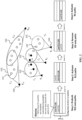
- FIG. 1 shows a device according to an embodiment of the invention.
- the device 100 is in particular configured to control network routing configurations in/of a network.
- the device 100 is to this end configured to obtain a predicted traffic matrix 101a and a plurality of traffic matrices 101, e.g. history traffic matrices.
- the device 100 may predict the predicted traffic matrix 101a itself, e.g. based on historical information about the traffic, or may receive the predicted traffic matrix 101a from another device or unit, e.g. a controller or a dedicated traffic matrix prediction device.
- the device 100 is further configured to determine a first cluster 102a and a second cluster 102b from a plurality of clusters 102.
- the clusters 102 of the plurality of clusters 102 are arranged in a hierarchical structure over the predicted traffic matrix 101a and the plurality of traffic matrices 101.
- the clusters 102 are allocated to at least two different hierarchy levels.
- a cluster 102 allocated to a higher hierarchy level includes at least two adjacent clusters 102 allocated to the hierarchy level below.
- each cluster 102 is associated with a routing configuration 104.
- the device 100 may be configured to maintain and manage (e.g. create) the clusters 102 itself, or may be provided with the information regarding the clusters 102 from another device.
- the first cluster 102a is allocated to a lower hierarchy level - for instance to the lowest hierarchy level - that contains the predicted traffic matrix 101a.
- the second cluster 102b is allocated to a higher hierarchy level - for instance to a hierarchy level that is one or more levels above the lower/lowest hierarchy level associated with the first cluster 102a - that includes at least the first cluster 102a and a third cluster 102c.
- the third cluster 102c is allocated to the lower/lowest hierarchy level that contains a current traffic matrix 101c. That is, the first cluster 102a and the third cluster 102c may be on the same hierarchy level, but this is not crucial.
- the second cluster 102c may contain further clusters 102, either in case that - in the hierarchical structure that is used - a cluster 102 on a higher hierarchy level includes more than two adjacent clusters 102 of the hierarchy level below, or in case that the second cluster 102c is more than one hierarchy level above the first and/or the third cluster 102.
- the device 100 is configured to determine a second routing configuration 104b associated with the second cluster 102b, and to activate the second routing configuration 104b as a network routing configuration.
- a smooth transition from the first routing configuration 104a associated with the first cluster 102a (including a first set of routes) to the second routing configuration 104b (including the first set of routes and a second set of routes, namely the routes of the third routing configuration 104c associated with the third cluster 102c), and further to the third routing configuration 104c (including only the second set of routes) can be achieved.
- FIG. 2 shows his in more detail.
- FIG. 2 shows how with the device 100 according to an embodiment of the invention, smoothly moving from one routing configuration R1 (corresponding to the first routing configuration 104a in FIG. 1 ) to another routing configuration R2 (corresponding to the third routing configuration 104c in FIG. 1 ) is possible, particularly by considering an overlapping parent routing configuration R12 (corresponding to the second routing configuration 104b in FIG. 1 ), which typically consist of the union of the routing configurations R1 and R2.
- the device 100 is configured to first slowly pre-fetch the parent routing configuration R12 in preferably all switches in the network. Once this is done, the device 100 is configured to remove routes of R1 from the switches. In this process, at a higher frequency, the device 100 may adjust load balancing weights in four steps:
- FIG. 2 describes graphically the above four-step process.
- FIG. 2 shows that parent routing configurations R12 and R23, associated with clusters C12 and C23 of traffic matrices on a higher hierarchy level, overlap with their child routing configurations R1, R2 and R3, which are associated with respectively clusters C1, C2 and C3 of traffic matrices on the hierarchy level below.
- FIG. 2 depicts the evolution of the forwarding table for one switch.
- the device 100 may be implemented in or as a SDN controller.
- the device 100 may include at least two modules: a Hierarchy of Cluster-Routing (HCR) generator module and a TE Configuration Maintenance (TCM) module.
- HCR Hierarchy of Cluster-Routing
- TCM TE Configuration Maintenance
- the HCR module starts from a set of Cluster-Routing solutions (i.e. routing configurations 104 associated with clusters 102) computed over clusters 102 of TMs 101. Each cluster 102 contains a set of subsequent TMs 101 and an associated routing configuration 104, wherein the routing configuration 104 is built to be robust against traffic variations within the cluster 102. These solutions may be provided by a clustering algorithm like a Clustered Robust Routing (CRR). Starting from this initial set, the HCR can build a set of parent Cluster-Routing solutions (i.e. higher-level routing configurations 104 associated with higher-level clusters 102) wherein each routing configuration 104 is the aggregate of pairs of consecutive Cluster-Routing solutions of the lower level. The operation can be iterated to build a hierarchy structure, wherein each parent routing configuration 104 is the aggregation of e.g. pairs of child routing configurations of the lower hierarchy level.
- CTR Clustered Robust Routing
- the TCM may decide, which routing configurations 104 computed by the HCR must be stored in and activated by switches 300 in the network, in order to smoothly move between two routing configurations 104. More specifically, when the TM 101 is moving towards a different cluster 102 than the one associate with the current routing configuration 104, a cluster-routing pair of higher level in the hierarchy may be selected. The module selects the cluster-routing pairs so that the cluster contains the predicted TM 101a. The associated routing configuration 104 (i.e., the routing associated to the selected cluster-routing pair 102/104) is then loaded in all switches 300. By construction, the set of routes in the new routing configuration 104 is a super-set of the routes currently configured in the network switches 300, since the selected cluster-routing pairs is at a higher level in the hierarchy.
- the TCM also computes the new split-ratio of the different routes that are pre-fetched in the switches 300. Since during the transition the pre-fetched configuration 104 contains a superset of the routes currently installed in the switches 300, the transition can be smooth. This means that old routes will not be abruptly removed, but the traffic is moved from the old routes to the new routes in a smooth way.
- Both modules may be continuously executed by the device 100.
- the HCR may thereby be executed at a lower frequency to update the clusters 102 and routing configurations 104 as new information is available, whereas the TCM may be executed at a higher frequency to keep the network in its best configuration as the system evolves, and to orchestrate the transitions between the routing configurations 104.
- the HCR module illustrated in FIG. 4 may include two sub-modules/functions: the Parent Cluster Generation and the Parent Routing Generation. Both modules may be executed on-demand whenever new routing solutions must be generated, e.g. as follows with respect to FIG. 4 .
- S1 Pairs of adjacent clusters 102 are merged together to create a parent cluster 102 including the union of the TMs 101 member of each cluster 102.
- a set of N-1 parent clusters 102 may be created.
- S2 For each parent cluster 102 a corresponding parent routing configuration 104 is generated, wherein the set of routes of each routing configuration 104 is the union of the routes of the two child clusters 102, and a set of load balancing weights over the new set of routers is computed.
- S3-S4 If the top of the hierarchy has not been reached yet (i.e. if there are at least two clusters 102 at the current level L) the process is reiterated starting from the set of cluster-routing pairs of the current hierarchy level L.
- the TCM module orchestrates the pre-fetching and the activation of the routing configurations 104. Whenever a transition from e.g. routing configuration R j L to R j+1 L is required, the module may pre-fetch the corresponding parent routing configuration R j L+1 , and then activate it by load balancing the traffic over the associated sets of routes. Routing configuration R j L may then be removed, and the R j+1 L routing configuration is pre-fetched. Finally, the transition towards R j+1 L is completed by load balancing the traffic over the final set of routes of R j+1 L of and by removing the routing configuration R j L+1 .
- S1.2 For each pair of subsequent clusters 102 (adjacent in time) at level L, the HCR creates a new cluster 102 of a higher level L+1 by merging the two clusters 102. To this end, the TMs 101 of the two clusters 102 of level L may be merged in a new set and the convex polyhedral approximating the convex hull of the new set may be computed. Only the extreme points of the convex polyhedral may be kept.
- the HCR For the new cluster C (i,i+1) L+1 , the HCR computes the associate routing configuration R (i,i+1) L+1 by merging the paths of the routing configurations R j(i) L and R j(i+1) L associated at the subsequent clusters C i L and C i+1 L of the lower level L.
- S1.4 If the actual level L is larger than the maximum number of levels in the hierarchy structure, the execution is stopped. Otherwise it is proceed with step S1.5.
- FIG. 6 Operations of the TCM module are shown in FIG. 6 , wherein:
- the following signals and commands can be used by the device 100:
- the result of the command C1 can be observed in the forwarding plane data structure of a switch 300, as it will be composed of:
- FIG. 8 shows a method 800 according to an embodiment of the invention.
- the method 800 can be used for controlling network routing configurations in a network.
- the method 800 may be carried out by the device 100 according to an embodiment of the invention.
- the method 800 comprises: A step 801 of obtaining a predicted traffic matrix 101a and a plurality of traffic matrices 101. Further, a step 802 of determining, from a plurality of clusters, a first cluster 102a allocated to a lower hierarchy level that contains the predicted traffic matrix 101a.
- the clusters 102 are arranged in a hierarchical structure over the predicted traffic matrix 101a and the plurality of traffic matrices 101, each of the plurality of clusters 102 is associated with a routing configuration 104, and the plurality of clusters 102 are allocated to at least two different hierarchy levels, a cluster 102 allocated to a higher hierarchy level including multiple adjacent clusters 102 allocated to the hierarchy level below.
- the method 800 comprises a step 803 of selecting, from the plurality of clusters 102, a second cluster 102b allocated to a higher hierarchy level that includes at least the first cluster 102a and a third cluster 102c allocated to the lower hierarchy level that contains a current traffic matrix 101c. Further, a step 804 of determining a second routing configuration 104b associated with the second cluster 102b. Finally, a step 805 of activating the second routing configuration 104b as a network routing configuration.
- embodiments of the present invention achieve multiple benefit.
- routing and load balancing can be decoupled, so that routing can be smoothly updated without degrading performance.
- the smoothness is obtained through the updating of load balancing weights.
- the embodiment of the invention work for routing updates in all TE approaches: Dynamic, Stable, Semi-Stable.
Landscapes
- Engineering & Computer Science (AREA)
- Computer Networks & Wireless Communication (AREA)
- Signal Processing (AREA)
- Data Mining & Analysis (AREA)
- Data Exchanges In Wide-Area Networks (AREA)
Description
- The present disclosure relates to the field of Traffic Engineering (TE) in a network, e.g. in a Software Defined Network (SDN). The disclosure is particularly concerned with routing traffic through the network. To this end, the disclosure relates to a device for controlling network routing configurations, and a corresponding method. The controlling of the network routing configurations is based on traffic matrices, which are grouped into clusters of different hierarchy level.
- TE plays a crucial role in network management, since it permits optimizing the utilization of network resources. Nowadays, e.g. SDN controllers or Path Computation Elements (PCE) integrate TE methods, in order to continuously optimize the network. However, sudden and unpredictable changes of the network, e.g. traffic variations and/or network failures, still pose a major challenge for conventional TE methods. The conventional TE methods, which have been devised to cope with network changes, can be broadly classified into three classes: Dynamic TE, Static TE and Semi-Static TE.
- Dynamic TE reconfigures the network each time a new event, like a traffic change or link failure, occurs in the network. A monitoring system is typically used by Dynamic TE methods, in order to collect information over a relatively short period of time, and to predict the future evolution of the network system. For example, a certain number of past traffic matrices is used to predict the next traffic matrix. This prediction is then used as an input of the Dynamic TE methods to reconfigure the network. Sophisticated methods, like linear programming, can be used to compute the best network configuration any time the traffic changes. However, reconfiguring the network too frequently can affect its stability, since programming hardware equipment takes time. Thus, too frequent network reconfigurations may result in worse performance. For this reason, TE methods reducing the number of network reconfigurations have also been proposed, e.g. methods that reconfigure the network only, if the benefit of the reconfiguring, as captured by an objective function, is larger than the benefit of further using the current network configuration. Nonetheless, the efficacy of Dynamic TE methods depends on the accuracy of the prediction method that is used to estimate the evolution of the system. Indeed, prediction errors can lead to large deviations of the network performance when optimized by Dynamic TE methods.
-
FIG. 9 shows an example of a general architecture of a SDN controller, wherein the information collected by a monitoring system is used by a Dynamic TE mechanism, in order to predict the next status of the network system, and to accordingly compute/update a network routing configuration. - In contrast to Dynamic TE described above, Stable TE computes a single configuration, which provides bounded performance loss, in case of prediction errors or unpredictable events, with respect to the optimal configuration. One of the first techniques of Stable TE is oblivious routing, which randomly selects the paths (routes) to connect a source and destination using a small subset of preselected nodes without using any knowledge of the traffic. Routing techniques that are totally oblivious to any traffic information and system changes can provide the highest robustness against any system evolution. However, the performance loss can quickly become large as the network size increases. For this reason, a partial knowledge of the traffic can also be integrated in the computation of the network configuration to improve oblivious routing.
- Some Stable TE methods compute a network configuration with performance guarantees for any traffic matrix (TM) that belongs to a bounded domain/set obtained using the information collected by the monitoring system. Other methods introduce different models for traffic uncertainness, e.g. by expressing the maximum load that can be expected over a link (pipe model) or an upper bound on the traffic emanating from a source node and directed to a destination node (hose model). Based on those models a network configuration with performance guarantees is computed. However, these uncertainness models include less information than the multiple TM approach, thus providing larger performance losses. To further improve the optimality of the solution, some methods consider only the most likely TMs for building the bounded set and computing of the optimal configuration. A penalty term is added in the optimization for less probable TMs. While such a method provides a good solution when the traffic varies smoothly, it cannot guarantee a feasible configuration against unexpected or unlikely events, since they are excluded from the computation.
- Finally, Semi-Static TE methods provide a limited set of routing configurations. This allows, on the one hand, to not reconfigure the network as frequently as in Dynamic TE. On the other hand, it also limits the robustness of each single routing configuration, thus reducing the performance loss. Some approaches divide the TM polytope in few subsets according to some dimensions, and compute a robust routing for each subset. While representing an initial attempt to split the TM domain in multiple parts, these approaches present several limitations: slicing directions are arbitrary; the number of created subsets is limited; and the partition is performed either in the traffic domain or in the time domain. Therefore, they can achieve only a limited performance improvement compared to the whole set of TM-space splitting possibilities. More sophisticated approaches, like affine and multi-polar routing, have been proposed more recently to overcome these limitations. In particular, these techniques compute a set of routing configurations that can be easily combined together to generate a routing configuration for a new traffic realization. However, the combination of multiple configurations can result in the utilization of a large number of paths and a flow split ratio that might not be handled by network devices.
- Among the whole set of Semi-static TE methods, only few of them consider how anomalies or wrong predictions of the TM space impact on the choice of the best split options. Within this set of methods, most of them just provide a robustness analysis of the original clustering technique, without explicitly designing a method to manage inaccurate predictions. In another approach, in order to manage anomalies, the normal operation TM polytope is expanded in the direction of the anomaly to include it. A new robust routing configuration is computed for the new polytope and used whenever the anomaly occurs. The limitations of this technique are the necessity of predicting any possible anomaly to properly enlarge the TM polytope and the absence of any reconfiguration frequency guarantee, as the configuration change is anomaly-driven.
- There are several ways, in which routing updates have been traditionally implemented. The most straightforward approach is "break-before-make", which consists in stopping the communication between source and destination, waiting for all packets on route to arrive at their destination, removing the relevant entries from the routing tables of the routers along the current route, establishing the new route by instructing the routers along the new route to have an entry for the connection, and at last, resuming the communication.
- However, in addition to a long time required to complete the update, this results in stopping the connection for a significant time period and possibly losing packets that are already traversing the original route. The opposite approach, "make-before-break", which activates the new path before deactivating the old one, can alleviate the packet dropping issue, but it still may lead to a slow transition process. More recently, update techniques based on synchronization of devices' clock have been proposed, in order to maintain network-wide consistency with micro-second accuracy. However, these techniques require strict time synchronization, which could be an inadmissible overhead.
-
WO 2018/219420 A1 discloses a system and method for providing a routing configuration built according to monitored traffic matrices and predicted traffic matrices. - The present invention is defined by the independent claims. Embodiments labelled as inventive embodiments in the following, which are not covered by the scope of protection defined by the independent claims, are to be understood as examples helpful for understanding the invention, but not as embodiments of the invention. In view of the above-mentioned TE methods and their disadvantages, embodiments of the present invention aim to provide an improved approach to TE. In particular, the invention aims for an improved control of network routing configurations over time. An objective is to allow for a smoother updating/changing of network routing configurations, particularly in case of sudden and unpredictable changes of the network. The approach of the invention should be usable together with Dynamic TE, Static TE or Semi-static TE methods. The updating/changing of the network routing configurations should include the smooth updating of routes (paths) of one routing configuration to the routes of another routing configuration.
- The objective is achieved by the embodiments of the invention as described in the enclosed independent claims. Advantageous implementations of the embodiments of the invention are further defined in the dependent claims.
- Changing all the routes of a network routing configuration to all the routes of another network routing configuration instantaneously, e.g. in case of a sudden and unpredictable network change, is very difficult, as this would require perfect synchronization between network equipments.
FIG. 10 shows a scenario, in which three Stable TE network routing configurations (R1, R2, and R3, each associated with a cluster C1, C2 and C3 of traffic matrices) are successively applied in all network equipments (e.g. switches). The main issue in such a scenario is that an abrupt network routing configuration change (e.g. from R1 to R2, or R2 to R3) can lead to packet losses, and "make-before break" approaches may not be always applicable without dead locks (i.e. without packet losses). - Thus, the embodiments of the invention base on the proposal to build a hierarchy of clusters of traffic matrices, which are each associated with a routing configuration. That is, effectively a hierarchy of routing configurations is built. This enables pre-fetching a parent routing configuration (higher hierarchy level) and then removing it in the transition between two child routing configurations (lower hierarchy level), in order to smoothly update the network from one child routing configuration to the other. Thereby, load balancing weights may also be used, in order to progressively move the traffic in the evolving set of routes of the respective routing configurations.
- A first aspect of the invention provides a device for controlling network routing configurations in a network according to
claim 1. A corresponding method is defined by claim 9. Further embodiments are defined by the dependent claims. - Notably, a cluster is/includes a set of TMs. The plurality of traffic matrices may be, or may be based on, past observations, synthetic traffic scenarios and/or past predictions (i.e. past predicted traffic matrices). A routing configuration is then assigned to each cluster, not to each individual TM included in the cluster. The routing configuration is valid for all TMs contained in the cluster. Clustering TMs is in principle known (see above). A network routing configuration is a routing configuration currently valid for the network. The first cluster is particularly the lowest-hierarchy-level cluster containing the predicted TM (parent clusters including that cluster also contain the predicted TM), and the third cluster is particularly the lowest-hierarchy-level cluster that contains the current traffic matrix.
- By setting the routing configuration of the second cluster as a network routing configuration, wherein the second cluster is of a higher hierarchy level and thus contains the routes of the routing configurations associated with each of the third cluster (containing the current traffic matrix) and of the first cluster (containing the predicted traffic matrix, i.e. the routes currently active), a smooth transition between the routing configurations is obtained. Further, a smooth transition can be obtained towards setting the routing configuration associated with the first cluster as the network routing configuration. A smooth transition is particularly possible in case of sudden and/or unpredictable network changes. The device of the first aspect is compatible with Dynamic TE, Static TE, or Semi-Static TE.
- It has to be noted that all devices, elements, units and means described in the present application could be implemented in the software or hardware elements or any kind of combination thereof. All steps which are performed by the various entities described in the present application as well as the functionalities described to be performed by the various entities are intended to mean that the respective entity is adapted to or configured to perform the respective steps and functionalities. Even if, in the following description of specific embodiments, a specific functionality or step to be performed by external entities is not reflected in the description of a specific detailed element of that entity which performs that specific step or functionality, it should be clear for a skilled person that these methods and functionalities can be implemented in respective software or hardware elements, or any kind of combination thereof.
- The above described aspects and implementation forms of the present invention will be explained in the following description of specific embodiments in relation to the enclosed drawings, in which
- FIG. 1
- shows a device according to an embodiment of the invention.
- FIG. 2
- shows an example procedure carried out by a device according to an embodiment of the invention.
- FIG.3
- shows a device according to the present invention implemented in an architecture of a SDN controller.
- FIG. 4
- shows a procedure performed by a device according to an embodiment of the invention.
- FIG. 5
- shows a procedure performed by a device according to an embodiment of the invention.
- FIG. 6
- shows a procedure performed by a device according to an embodiment of the invention.
- FIG. 7
- shows in (a) a device according to an embodiment of the invention implemented in an architecture of a SDN controller, which provides signals C1 and C2 to switches, and shows in (b) a forwarding table at a switch after pre-fetching signal C1.
- FIG. 8
- shows a method according to an embodiment of the invention.
- FIG. 9
- shows an example of three clusters of traffic matrices and three associated routing configurations.
- FIG. 10
- shows an example architecture of a SDN controller configured for Dynamic TE.
-
FIG. 1 shows a device according to an embodiment of the invention. Thedevice 100 is in particular configured to control network routing configurations in/of a network. - The
device 100 is to this end configured to obtain a predictedtraffic matrix 101a and a plurality oftraffic matrices 101, e.g. history traffic matrices. Thedevice 100 may predict the predictedtraffic matrix 101a itself, e.g. based on historical information about the traffic, or may receive the predictedtraffic matrix 101a from another device or unit, e.g. a controller or a dedicated traffic matrix prediction device. - The
device 100 is further configured to determine afirst cluster 102a and asecond cluster 102b from a plurality ofclusters 102. Theclusters 102 of the plurality ofclusters 102 are arranged in a hierarchical structure over the predictedtraffic matrix 101a and the plurality oftraffic matrices 101. In particular, theclusters 102 are allocated to at least two different hierarchy levels. Thereby, acluster 102 allocated to a higher hierarchy level includes at least twoadjacent clusters 102 allocated to the hierarchy level below. Further, eachcluster 102 is associated with arouting configuration 104. Thedevice 100 may be configured to maintain and manage (e.g. create) theclusters 102 itself, or may be provided with the information regarding theclusters 102 from another device. - The
first cluster 102a is allocated to a lower hierarchy level - for instance to the lowest hierarchy level - that contains the predictedtraffic matrix 101a. Thesecond cluster 102b is allocated to a higher hierarchy level - for instance to a hierarchy level that is one or more levels above the lower/lowest hierarchy level associated with thefirst cluster 102a - that includes at least thefirst cluster 102a and athird cluster 102c. Thereby, thethird cluster 102c is allocated to the lower/lowest hierarchy level that contains acurrent traffic matrix 101c. That is, thefirst cluster 102a and thethird cluster 102c may be on the same hierarchy level, but this is not crucial. Thesecond cluster 102c may containfurther clusters 102, either in case that - in the hierarchical structure that is used - acluster 102 on a higher hierarchy level includes more than twoadjacent clusters 102 of the hierarchy level below, or in case that thesecond cluster 102c is more than one hierarchy level above the first and/or thethird cluster 102. - Further, the
device 100 is configured to determine asecond routing configuration 104b associated with thesecond cluster 102b, and to activate thesecond routing configuration 104b as a network routing configuration. - Thus, a smooth transition from the
first routing configuration 104a associated with thefirst cluster 102a (including a first set of routes) to thesecond routing configuration 104b (including the first set of routes and a second set of routes, namely the routes of thethird routing configuration 104c associated with thethird cluster 102c), and further to thethird routing configuration 104c (including only the second set of routes) can be achieved. -
FIG. 2 shows his in more detail. In particular,FIG. 2 shows how with thedevice 100 according to an embodiment of the invention, smoothly moving from one routing configuration R1 (corresponding to thefirst routing configuration 104a inFIG. 1 ) to another routing configuration R2 (corresponding to thethird routing configuration 104c inFIG. 1 ) is possible, particularly by considering an overlapping parent routing configuration R12 (corresponding to thesecond routing configuration 104b inFIG. 1 ), which typically consist of the union of the routing configurations R1 and R2. - The
device 100 is configured to first slowly pre-fetch the parent routing configuration R12 in preferably all switches in the network. Once this is done, thedevice 100 is configured to remove routes of R1 from the switches. In this process, at a higher frequency, thedevice 100 may adjust load balancing weights in four steps: - Step 1 (pre-fetching of R12): load balancing is achieved on the set of routes of R1 as the new routes of R12 coming from R2 are not all installed.
- Step 2 (activation of R12): load balancing is achieved on R12 as all routes are installed.
- Step 3 (removal of R1): load balancing is achieved on R2 only, while R1 routes are being removed.
- Step 4 (activation of R2): load balancing is achieved on R2.
-
FIG. 2 describes graphically the above four-step process. On the top,FIG. 2 shows that parent routing configurations R12 and R23, associated with clusters C12 and C23 of traffic matrices on a higher hierarchy level, overlap with their child routing configurations R1, R2 and R3, which are associated with respectively clusters C1, C2 and C3 of traffic matrices on the hierarchy level below. At the bottom,FIG. 2 depicts the evolution of the forwarding table for one switch. - As illustrated in
FIG. 3 , thedevice 100 may be implemented in or as a SDN controller. Thedevice 100 may include at least two modules: a Hierarchy of Cluster-Routing (HCR) generator module and a TE Configuration Maintenance (TCM) module. - The HCR module starts from a set of Cluster-Routing solutions (i.e. routing
configurations 104 associated with clusters 102) computed overclusters 102 ofTMs 101. Eachcluster 102 contains a set ofsubsequent TMs 101 and an associatedrouting configuration 104, wherein therouting configuration 104 is built to be robust against traffic variations within thecluster 102. These solutions may be provided by a clustering algorithm like a Clustered Robust Routing (CRR). Starting from this initial set, the HCR can build a set of parent Cluster-Routing solutions (i.e. higher-level routing configurations 104 associated with higher-level clusters 102) wherein eachrouting configuration 104 is the aggregate of pairs of consecutive Cluster-Routing solutions of the lower level. The operation can be iterated to build a hierarchy structure, wherein eachparent routing configuration 104 is the aggregation of e.g. pairs of child routing configurations of the lower hierarchy level. - The TCM may decide, which routing
configurations 104 computed by the HCR must be stored in and activated byswitches 300 in the network, in order to smoothly move between two routingconfigurations 104. More specifically, when theTM 101 is moving towards adifferent cluster 102 than the one associate with thecurrent routing configuration 104, a cluster-routing pair of higher level in the hierarchy may be selected. The module selects the cluster-routing pairs so that the cluster contains the predictedTM 101a. The associated routing configuration 104 (i.e., the routing associated to the selected cluster-routing pair 102/104) is then loaded in all switches 300. By construction, the set of routes in thenew routing configuration 104 is a super-set of the routes currently configured in the network switches 300, since the selected cluster-routing pairs is at a higher level in the hierarchy. - The TCM also computes the new split-ratio of the different routes that are pre-fetched in the
switches 300. Since during the transition thepre-fetched configuration 104 contains a superset of the routes currently installed in theswitches 300, the transition can be smooth. This means that old routes will not be abruptly removed, but the traffic is moved from the old routes to the new routes in a smooth way. - Both modules may be continuously executed by the
device 100. The HCR may thereby be executed at a lower frequency to update theclusters 102 androuting configurations 104 as new information is available, whereas the TCM may be executed at a higher frequency to keep the network in its best configuration as the system evolves, and to orchestrate the transitions between the routingconfigurations 104. - The HCR module illustrated in
FIG. 4 may include two sub-modules/functions: the Parent Cluster Generation and the Parent Routing Generation. Both modules may be executed on-demand whenever new routing solutions must be generated, e.g. as follows with respect toFIG. 4 .S1: Pairs of adjacent clusters 102 are merged together to create aparent cluster 102 including the union of theTMs 101 member of eachcluster 102. A set of N-1parent clusters 102 may be created.S2: For each parent cluster 102 a correspondingparent routing configuration 104 is generated, wherein the set of routes of eachrouting configuration 104 is the union of the routes of the twochild clusters 102, and a set of load balancing weights over the new set of routers is computed.S3-S4: If the top of the hierarchy has not been reached yet (i.e. if there are at least two clusters 102 at the current level L) the process is reiterated starting from the set of cluster-routing pairs of the current hierarchy level L. - The TCM module orchestrates the pre-fetching and the activation of the
routing configurations 104. Whenever a transition from e.g. routing configuration Rj L to Rj+1 L is required, the module may pre-fetch the corresponding parent routing configuration Rj L+1, and then activate it by load balancing the traffic over the associated sets of routes. Routing configuration Rj L may then be removed, and the Rj+1 L routing configuration is pre-fetched. Finally, the transition towards Rj+1 L is completed by load balancing the traffic over the final set of routes of Rj+1 L of and by removing the routing configuration Rj L+1. - Operations performed by the HCR module are detailed in
FIG. 5 and described hereafter.S1.1: The HCR module initialize the level of the hierarchy: L=1. S1.2: For each pair of subsequent clusters 102 (adjacent in time) at level L, the HCR creates a new cluster 102 of a higher level L+1 by merging the twoclusters 102. To this end, theTMs 101 of the twoclusters 102 of level L may be merged in a newset and the convex polyhedral approximating the convex hull of the new set may be computed. Only the extreme points of the convex polyhedral may be kept. S1.3: For the new cluster C(i,i+1) L+1 , the HCR computes the associate routing configuration R(i,i+1) L+1 by merging the paths of the routing configurations Rj(i) L and Rj(i+1) L associated at the subsequent clusters Ci L and Ci+1 L of the lower level L. S1.4: If the actual level L is larger than the maximum number of levels in the hierarchy structure, the execution is stopped. Otherwise it is proceed with step S1.5. S1.5: The HCR increments the level of the hierarchy: L:=L+1. - Operations of the TCM module are shown in
FIG. 6 , wherein: - The TM y(t) is represented as a vector where each entry represents an origin-destination flow. The number of dimensions is equal to the number of OD flows.
- A cluster C(t) is represented by its extreme points, namely a list of vectors. Each vector of the list represent a pseudo-matrix where each entry is an origin-destination flow of size decided by the clustering module.
- A TE/routing configuration R(t) is a matrix that associates to each origin-destination flow the set of links that are used to route the traffic. R(t) has a number of rows equal to the number of links and a number of columns equal to the number of origin-destination flows. The product R(t) * y(t) provides the traffic load of links at time t.
- As illustrated in
FIG. 7(a) , the following signals and commands can be used by the device 100:C1: The device 100 may pre-fetch forwarding plane tables containing rules that are a super-set of rules previously installed in the switches 300 (the new forwarding rules may overlap forwarding rules installed before sending this new command C1).C2: The device 100 may update load balancing weights to activate thenew routing configurations 104 as network routing configuration. The number of weights sent for each tunnel may not be fixed, but may vary according to a size of thepre-fetched routing configuration 104. - As illustrated in
FIG. 7(b) , the result of the command C1 can be observed in the forwarding plane data structure of aswitch 300, as it will be composed of: - Load balancing weights that are non-zero for routes belonging to the active routing configuration (R1 in
FIG. 7(b) ). - Every time the
network routing configuration 104 is updated, new routes that partially overlap with theactive routing configuration 104 can be observed from forwarding rules (R12 inFIG. 7(b) ). -
FIG. 8 shows amethod 800 according to an embodiment of the invention. Themethod 800 can be used for controlling network routing configurations in a network. Themethod 800 may be carried out by thedevice 100 according to an embodiment of the invention. - The
method 800 comprises: Astep 801 of obtaining a predictedtraffic matrix 101a and a plurality oftraffic matrices 101. Further, astep 802 of determining, from a plurality of clusters, afirst cluster 102a allocated to a lower hierarchy level that contains the predictedtraffic matrix 101a. Thereby, theclusters 102 are arranged in a hierarchical structure over the predictedtraffic matrix 101a and the plurality oftraffic matrices 101, each of the plurality ofclusters 102 is associated with arouting configuration 104, and the plurality ofclusters 102 are allocated to at least two different hierarchy levels, acluster 102 allocated to a higher hierarchy level including multipleadjacent clusters 102 allocated to the hierarchy level below. - Further, the
method 800 comprises astep 803 of selecting, from the plurality ofclusters 102, asecond cluster 102b allocated to a higher hierarchy level that includes at least thefirst cluster 102a and athird cluster 102c allocated to the lower hierarchy level that contains acurrent traffic matrix 101c. Further, astep 804 of determining asecond routing configuration 104b associated with thesecond cluster 102b. Finally, astep 805 of activating thesecond routing configuration 104b as a network routing configuration. - In summary, embodiments of the present invention achieve multiple benefit. In particular, routing and load balancing can be decoupled, so that routing can be smoothly updated without degrading performance. The smoothness is obtained through the updating of load balancing weights. The embodiment of the invention work for routing updates in all TE approaches: Dynamic, Stable, Semi-Stable.
- The present invention has been described in conjunction with various embodiments as examples as well as implementations. However, other variations can be understood and effected by those persons skilled in the art and practicing the claimed invention, from the studies of the drawings, this disclosure and the independent claims. In the claims as well as in the description the word "comprising" does not exclude other elements or steps and the indefinite article "a" or "an" does not exclude a plurality.
| S1: | The |
| S2: | The |
| S3: | If the cluster C(t) that contains the current TM (at time t) is different from the cluster C(t+1) that contains the next predicted TM (i.e., the predicted |
| period of time t+1 belongs to a cluster different than the current one), continue to step S4. | |
| Otherwise, go to STOP. | |
| S4: | The |
| S5: | The |
| S6: | The |
| S7: | Once the command C1 has been received by all |
| S8: | The |
Claims (9)
- A device for controlling (100) network routing configurations in a network, the device (100) being configured to:obtain a predicted traffic matrix (101a) of a next time period and a plurality of history traffic matrices (101) of past time periods;determine, from a plurality of clusters (102), wherein the clusters (102) are arranged in a hierarchical structure and contain the predicted traffic matrix (101a) and the plurality of history traffic matrices (101) and wherein each cluster (102) contains a respective set of traffic matrices, a first cluster (102a) allocated to a first hierarchy level of the hierarchical structure, wherein the first cluster (102a) contains a first set of traffic matrices including a traffic matrix that corresponds to the predicted traffic matrix (101a), wherein- each of the plurality of clusters (102) is associated with a routing configuration (104),- each of the plurality of clusters (102) is allocated to one of at least two different hierarchy levels of the hierarchical structure, and- each cluster (102), which is allocated to a respective hierarchy level higher than the lowest hierarchy level of the hierarchical structure, includes the sets of traffic matrices that are included in multiple adjacent clusters (102) allocated to the hierarchy level below the respective hierarchy level in the hierarchical structure;select, from the plurality of clusters (102), a second cluster (102b) allocated to a second hierarchy level of the hierarchical structure, wherein the second cluster (102b) contains a second set of traffic matrices comprising at least the first set of traffic matrices of the first cluster (102a) and a third set of traffic matrices of a third cluster (102c) allocated to the first hierarchy level, wherein the third set of traffic matrices (102c) includes a current traffic matrix (101c) of a current time period, and wherein the second hierarchy level is higher than the first hierarchy level in the hierarchical structure;determine a second routing configuration (104b) associated with the second cluster (102b), wherein the second routing configuration (104b) includes a first set of routes and a second set of routes, wherein the first set of routes is included in a first routing configuration (104a) associated with the first cluster (102a) and the second set of routes is included in a third routing configuration (104c) associated with the third cluster (102c); andactivate the second routing configuration (104b) as a network routing configuration;wherein the device (100) is further configured to:
merge at least two adjacent clusters (102), which are allocated to the same hierarchy level of the hierarchical structure, to generate a new cluster (102) allocated to a hierarchy level higher in the hierarchical structure than said same hierarchy level, wherein the device (100) is further configured to, for merging the at least two adjacent clusters (102):merge the sets of traffic matrices (101) contained in each of the at least two adjacent clusters (102) into a preliminary set of traffic matrices (101);calculate a convex polyhedral approximating the convex hull of the preliminary set of traffic matrices; andkeep only those traffic matrices of the preliminary set of traffic matrices, which correspond to extreme points of the convex polyhedral, as a new set of traffic matrices of the new cluster (102). - The device (100) according to claim 1, the device being further configured to, for activating the second routing configuration (104b):
send a command indicating the second routing configuration (104b), which includes the first set of routes and the second set of routes and is associated with the second set of traffic matrices of the second cluster, to a plurality of or all switches (300) in the network. - The device (100) according to claim 1 or 2, the device being further configured to, for activating the second routing configuration (104b):determine a load balancing weight for each route of the first set of routes and the second set of routes included in the second routing configuration (104b) for decoupling load balancing from routing; andactivate the plurality of routes of the second routing configuration (104b).
- The device (100) according to claim 3, the device being further configured to, for activating the second routing configuration (104b):
send a command indicating the determined weights of the plurality of routes of the second routing configuration (104b) to a plurality of or all switches (300) in the network. - The device (100) according to any one of the claims 1 to 4, the device being further configured to:
deactivate a particular routing configuration (104) as a particular network routing configuration if the particular routing configuration (104) is associated with a cluster (102) that does not contain a traffic matrix corresponding to the predicted traffic matrix (101a). - The device (100) according to any one of the claims 1 to 5, the device being further configured to:
determine the first routing configuration (104a) associated with the first cluster (102a) and activate the first routing configuration (104a) as another network routing configuration. - The device (100) according to claim 1, the device being further configured to:
generate a new routing configuration (104) associated with the new cluster (102) based on the routing configurations (104) associated respectively with each of the at least two adjacent clusters (102). - The device (100) according to claim 1 or 7, the device being configured to:
generate the plurality of clusters (102) allocated to the at least two hierarchy levels of the hierarchical structure. - A method (800) for controlling network routing configurations in a network, the method (800) comprisingobtaining a predicted traffic matrix (101a) of a next time period and a plurality of history traffic matrices (101) of past time periods;determining, from a plurality of clusters (102), wherein the clusters (102) are arranged in a hierarchical structure and contain the predicted traffic matrix (101a) and the plurality of history traffic matrices (101) wherein each cluster (102) contains a respective set of traffic matrices, a first cluster (102a) allocated to a first hierarchy level of the hierarchical structure, wherein the first cluster (102a) contains a first set of traffic matrices including a traffic matrix that corresponds to the predicted traffic matrix (101a), wherein- each of the plurality of clusters (102) is associated with a routing configuration (104),- each of the plurality of clusters (102) is allocated to one of at least two different hierarchy levels of the hierarchical structure, and- each cluster (102), which is allocated to a respective hierarchy level higher than the lowest hierarchy level of the hierarchical structure, includes the sets of traffic matrices that are included in multiple adjacent clusters (102) allocated to the hierarchy level below the respective hierarchy level in the hierarchical structure;selecting, from the plurality of clusters (102), a second cluster (102b) allocated to a second hierarchy level of the hierarchical structure, wherein the second cluster (102b) contains a second set of traffic matrices comprising at least the first set of traffic matrices of the first cluster (102a) and a third set of traffic matrices of a third cluster (102c) allocated to the first hierarchy level, wherein the third set of traffic matrices (102c) includes a current traffic matrix (101c) of a current time period, and wherein the second hierarchy level is higher than the first hierarchy level in the hierarchical structure;determining a second routing configuration (104b) associated with the second cluster (102b), wherein the second routing configuration (104b) includes a first set of routes and a second set of routes, wherein the first set of routes is included in a first routing configuration (104a) associated with the first cluster (102a) and the second set of routes is included in a third routing configuration (104c) associated with the third cluster (102c); andactivating the second routing configuration (104b) as a network routing configuration;wherein the method (800) further comprises:merging at least two adjacent clusters (102), which are allocated to the same hierarchy level of the hierarchical structure, to generate a new cluster (102) allocated to a hierarchy level higher in the hierarchical structure than said same hierarchy level, wherein the method (800) further comprises,for merging the at least two adjacent clusters (102):merging the sets of traffic matrices (101) contained in each of the at least two adjacent clusters (102) into a preliminary set of traffic matrices (101);calculating a convex polyhedral approximating the convex hull of the preliminary set of traffic matrices; andkeeping only those traffic matrices of the preliminary set of traffic matrices, which correspond to extreme points of the convex polyhedral, as a new set of traffic matrices of the new cluster (102).
Applications Claiming Priority (1)
| Application Number | Priority Date | Filing Date | Title |
|---|---|---|---|
| PCT/EP2019/053098 WO2020160780A1 (en) | 2019-02-08 | 2019-02-08 | Devices and method for controlling network routing configurations |
Publications (2)
| Publication Number | Publication Date |
|---|---|
| EP3906640A1 EP3906640A1 (en) | 2021-11-10 |
| EP3906640B1 true EP3906640B1 (en) | 2024-07-31 |
Family
ID=65365962
Family Applications (1)
| Application Number | Title | Priority Date | Filing Date |
|---|---|---|---|
| EP19704597.4A Active EP3906640B1 (en) | 2019-02-08 | 2019-02-08 | Devices and method for controlling network routing configurations |
Country Status (5)
| Country | Link |
|---|---|
| US (1) | US12010013B2 (en) |
| EP (1) | EP3906640B1 (en) |
| CN (1) | CN113316917B (en) |
| BR (1) | BR112021015465A2 (en) |
| WO (1) | WO2020160780A1 (en) |
Families Citing this family (2)
| Publication number | Priority date | Publication date | Assignee | Title |
|---|---|---|---|---|
| BR112021015465A2 (en) * | 2019-02-08 | 2021-10-05 | Huawei Technologies Co., Ltd. | DEVICES AND METHOD FOR CONTROLLING NETWORK ROUTING SETTINGS |
| US12235726B2 (en) * | 2021-10-03 | 2025-02-25 | VMware LLC | Implementing state change in a hierarchy of resources in an SDDC |
Family Cites Families (21)
| Publication number | Priority date | Publication date | Assignee | Title |
|---|---|---|---|---|
| US6574669B1 (en) | 1998-08-31 | 2003-06-03 | Nortel Networks Limited | Method and apparatus for routing traffic within a network utilizing linear optimization |
| US7388842B1 (en) | 2003-03-13 | 2008-06-17 | At&T Corp. | Method and apparatus for efficient routing of variable traffic |
| US7433315B2 (en) | 2004-01-07 | 2008-10-07 | Lucent Technologies Inc. | Method for fast network re-optimization |
| US7957266B2 (en) | 2004-05-28 | 2011-06-07 | Alcatel-Lucent Usa Inc. | Efficient and robust routing independent of traffic pattern variability |
| US8228803B1 (en) * | 2006-06-28 | 2012-07-24 | At&T Intellectual Property Ii, L.P. | Method and apparatus for finding critical traffic matrices |
| CN101652959B (en) * | 2007-03-12 | 2013-01-30 | Lm爱立信电话有限公司 | Arrangement and method relating to network management |
| US7864751B2 (en) | 2007-08-14 | 2011-01-04 | Greenberg Albert G | Traffic engineering method, system and computer program product for managing traffic over dynamic networks during both normal and unexpected traffic scenarios |
| US8477597B2 (en) * | 2009-05-27 | 2013-07-02 | Yin Zhang | Method and system for resilient routing reconfiguration |
| CN102143042B (en) * | 2010-07-09 | 2014-04-16 | 华为技术有限公司 | Virtual cluster router system and flow sharing method thereof, controller and sub routers |
| US8773992B2 (en) * | 2010-10-11 | 2014-07-08 | At&T Intellectual Property I, L.P. | Methods and apparatus for hierarchical routing in communication networks |
| US9680665B2 (en) * | 2014-04-24 | 2017-06-13 | Futurewei Technologies, Inc. | Apparatus and method for dynamic hybrid routing in SDN networks to avoid congestion and balance loads under changing traffic load |
| GB2543017A (en) * | 2014-11-28 | 2017-04-12 | Aria Networks Ltd | Telecommunications network planning |
| US9552327B2 (en) * | 2015-01-29 | 2017-01-24 | Knuedge Incorporated | Memory controller for a network on a chip device |
| US9807019B2 (en) | 2015-03-30 | 2017-10-31 | Alcatel Lucent | Offline optimization for traffic engineering with segment routing |
| CN104935476B (en) * | 2015-05-20 | 2018-04-06 | 电子科技大学 | A kind of network traffics matrix measuring method based on SDN |
| US10659333B2 (en) * | 2016-03-24 | 2020-05-19 | Cisco Technology, Inc. | Detection and analysis of seasonal network patterns for anomaly detection |
| CN107317697B (en) * | 2017-05-25 | 2020-01-07 | 清华大学 | A Routing Configuration Method for OSPF and SDN Hybrid Network |
| WO2018219420A1 (en) * | 2017-05-29 | 2018-12-06 | Huawei Technologies Co., Ltd. | Apparatus and method for providing a robust routing configuration |
| US10581736B1 (en) * | 2018-11-13 | 2020-03-03 | At&T Intellectual Property I, L.P. | Traffic matrix prediction and fast reroute path computation in packet networks |
| BR112021015465A2 (en) * | 2019-02-08 | 2021-10-05 | Huawei Technologies Co., Ltd. | DEVICES AND METHOD FOR CONTROLLING NETWORK ROUTING SETTINGS |
| US11663053B2 (en) * | 2020-08-14 | 2023-05-30 | Google Llc | Clustering processes using traffic data |
-
2019
- 2019-02-08 BR BR112021015465-5A patent/BR112021015465A2/en unknown
- 2019-02-08 WO PCT/EP2019/053098 patent/WO2020160780A1/en not_active Ceased
- 2019-02-08 EP EP19704597.4A patent/EP3906640B1/en active Active
- 2019-02-08 CN CN201980089425.5A patent/CN113316917B/en active Active
-
2021
- 2021-08-06 US US17/396,367 patent/US12010013B2/en active Active
Also Published As
| Publication number | Publication date |
|---|---|
| EP3906640A1 (en) | 2021-11-10 |
| CN113316917A (en) | 2021-08-27 |
| CN113316917B (en) | 2023-02-28 |
| BR112021015465A2 (en) | 2021-10-05 |
| US20210367882A1 (en) | 2021-11-25 |
| US12010013B2 (en) | 2024-06-11 |
| WO2020160780A1 (en) | 2020-08-13 |
Similar Documents
| Publication | Publication Date | Title |
|---|---|---|
| EP3047609B1 (en) | Systems and method for reconfiguration of routes | |
| US20220414500A1 (en) | Network devices | |
| US11637755B2 (en) | SDN network system, controller, and controlling method | |
| CN105900393B (en) | Flow Behavior-Driven Dynamic Partitioning for Distributed Traffic Engineering in SDN | |
| US12126529B2 (en) | Multi-tier deterministic networking | |
| Baldine et al. | Traffic adaptive WDM networks: A study of reconfiguration issues | |
| KR101072365B1 (en) | Method for operating mobile ad hoc network and mobile ad hoc network | |
| EP2656551B1 (en) | Communications network management | |
| US10581736B1 (en) | Traffic matrix prediction and fast reroute path computation in packet networks | |
| WO2012085519A1 (en) | Communications network management | |
| Majdoub et al. | DQR: an efficient deep Q-based routing approach in multi-controller software defined WAN (SD-WAN) | |
| He et al. | Toward a flexible design of SDN dynamic control plane: An online optimization approach | |
| US12010013B2 (en) | Devices and method for controlling network routing configurations | |
| CN118984273B (en) | A network controller and network switching device configuration method | |
| WO2006045996A1 (en) | Resource allocation | |
| Bilen | Prediction and Prioritization of Hardware Failures in 6G Small Cell Networks | |
| WO2018219420A1 (en) | Apparatus and method for providing a robust routing configuration | |
| Capone et al. | Apparatus and method to provide a robust routing configuration | |
| Gausseran et al. | Poster: Don't interrupt me when you reconfigure my service function chains | |
| RU2402171C1 (en) | Method for generation of control data exchange network structure | |
| Poularakis et al. | SDN Control Plane Optimization | |
| Tsukuda et al. | Reducing Inconsistency between Software-Defined Networking Controllers | |
| Filali | Flexible resource management in next-generation networks with SDN | |
| CA2210207A1 (en) | Distributed preconfiguration of spare capacity in closed paths for network restoration | |
| CN118368669A (en) | Dynamic SFC mapping method and device for satellite-ground integrated network |
Legal Events
| Date | Code | Title | Description |
|---|---|---|---|
| STAA | Information on the status of an ep patent application or granted ep patent |
Free format text: STATUS: UNKNOWN |
|
| STAA | Information on the status of an ep patent application or granted ep patent |
Free format text: STATUS: THE INTERNATIONAL PUBLICATION HAS BEEN MADE |
|
| PUAI | Public reference made under article 153(3) epc to a published international application that has entered the european phase |
Free format text: ORIGINAL CODE: 0009012 |
|
| STAA | Information on the status of an ep patent application or granted ep patent |
Free format text: STATUS: REQUEST FOR EXAMINATION WAS MADE |
|
| 17P | Request for examination filed |
Effective date: 20210804 |
|
| AK | Designated contracting states |
Kind code of ref document: A1 Designated state(s): AL AT BE BG CH CY CZ DE DK EE ES FI FR GB GR HR HU IE IS IT LI LT LU LV MC MK MT NL NO PL PT RO RS SE SI SK SM TR |
|
| DAV | Request for validation of the european patent (deleted) | ||
| DAX | Request for extension of the european patent (deleted) | ||
| STAA | Information on the status of an ep patent application or granted ep patent |
Free format text: STATUS: EXAMINATION IS IN PROGRESS |
|
| 17Q | First examination report despatched |
Effective date: 20221124 |
|
| REG | Reference to a national code |
Ref country code: DE Ref legal event code: R079 Free format text: PREVIOUS MAIN CLASS: H04L0012260000 Ipc: H04L0043040000 Ref document number: 602019056062 Country of ref document: DE |
|
| GRAP | Despatch of communication of intention to grant a patent |
Free format text: ORIGINAL CODE: EPIDOSNIGR1 |
|
| STAA | Information on the status of an ep patent application or granted ep patent |
Free format text: STATUS: GRANT OF PATENT IS INTENDED |
|
| RIC1 | Information provided on ipc code assigned before grant |
Ipc: H04L 45/42 20220101ALI20240305BHEP Ipc: H04L 45/02 20220101ALI20240305BHEP Ipc: H04L 43/04 20220101AFI20240305BHEP |
|
| INTG | Intention to grant announced |
Effective date: 20240325 |
|
| GRAS | Grant fee paid |
Free format text: ORIGINAL CODE: EPIDOSNIGR3 |
|
| GRAA | (expected) grant |
Free format text: ORIGINAL CODE: 0009210 |
|
| STAA | Information on the status of an ep patent application or granted ep patent |
Free format text: STATUS: THE PATENT HAS BEEN GRANTED |
|
| AK | Designated contracting states |
Kind code of ref document: B1 Designated state(s): AL AT BE BG CH CY CZ DE DK EE ES FI FR GB GR HR HU IE IS IT LI LT LU LV MC MK MT NL NO PL PT RO RS SE SI SK SM TR |
|
| REG | Reference to a national code |
Ref country code: CH Ref legal event code: EP Ref country code: GB Ref legal event code: FG4D |
|
| REG | Reference to a national code |
Ref country code: DE Ref legal event code: R096 Ref document number: 602019056062 Country of ref document: DE |
|
| REG | Reference to a national code |
Ref country code: IE Ref legal event code: FG4D |
|
| REG | Reference to a national code |
Ref country code: LT Ref legal event code: MG9D |
|
| REG | Reference to a national code |
Ref country code: NL Ref legal event code: MP Effective date: 20240731 |
|
| PG25 | Lapsed in a contracting state [announced via postgrant information from national office to epo] |
Ref country code: PT Free format text: LAPSE BECAUSE OF FAILURE TO SUBMIT A TRANSLATION OF THE DESCRIPTION OR TO PAY THE FEE WITHIN THE PRESCRIBED TIME-LIMIT Effective date: 20241202 |
|
| REG | Reference to a national code |
Ref country code: AT Ref legal event code: MK05 Ref document number: 1709594 Country of ref document: AT Kind code of ref document: T Effective date: 20240731 |
|
| PG25 | Lapsed in a contracting state [announced via postgrant information from national office to epo] |
Ref country code: PT Free format text: LAPSE BECAUSE OF FAILURE TO SUBMIT A TRANSLATION OF THE DESCRIPTION OR TO PAY THE FEE WITHIN THE PRESCRIBED TIME-LIMIT Effective date: 20241202 |
|
| PG25 | Lapsed in a contracting state [announced via postgrant information from national office to epo] |
Ref country code: NO Free format text: LAPSE BECAUSE OF FAILURE TO SUBMIT A TRANSLATION OF THE DESCRIPTION OR TO PAY THE FEE WITHIN THE PRESCRIBED TIME-LIMIT Effective date: 20241031 |
|
| PG25 | Lapsed in a contracting state [announced via postgrant information from national office to epo] |
Ref country code: GR Free format text: LAPSE BECAUSE OF FAILURE TO SUBMIT A TRANSLATION OF THE DESCRIPTION OR TO PAY THE FEE WITHIN THE PRESCRIBED TIME-LIMIT Effective date: 20241101 Ref country code: FI Free format text: LAPSE BECAUSE OF FAILURE TO SUBMIT A TRANSLATION OF THE DESCRIPTION OR TO PAY THE FEE WITHIN THE PRESCRIBED TIME-LIMIT Effective date: 20240731 Ref country code: NL Free format text: LAPSE BECAUSE OF FAILURE TO SUBMIT A TRANSLATION OF THE DESCRIPTION OR TO PAY THE FEE WITHIN THE PRESCRIBED TIME-LIMIT Effective date: 20240731 Ref country code: PL Free format text: LAPSE BECAUSE OF FAILURE TO SUBMIT A TRANSLATION OF THE DESCRIPTION OR TO PAY THE FEE WITHIN THE PRESCRIBED TIME-LIMIT Effective date: 20240731 |
|
| PG25 | Lapsed in a contracting state [announced via postgrant information from national office to epo] |
Ref country code: BG Free format text: LAPSE BECAUSE OF FAILURE TO SUBMIT A TRANSLATION OF THE DESCRIPTION OR TO PAY THE FEE WITHIN THE PRESCRIBED TIME-LIMIT Effective date: 20240731 |
|
| PG25 | Lapsed in a contracting state [announced via postgrant information from national office to epo] |
Ref country code: LV Free format text: LAPSE BECAUSE OF FAILURE TO SUBMIT A TRANSLATION OF THE DESCRIPTION OR TO PAY THE FEE WITHIN THE PRESCRIBED TIME-LIMIT Effective date: 20240731 |
|
| PG25 | Lapsed in a contracting state [announced via postgrant information from national office to epo] |
Ref country code: AT Free format text: LAPSE BECAUSE OF FAILURE TO SUBMIT A TRANSLATION OF THE DESCRIPTION OR TO PAY THE FEE WITHIN THE PRESCRIBED TIME-LIMIT Effective date: 20240731 Ref country code: IS Free format text: LAPSE BECAUSE OF FAILURE TO SUBMIT A TRANSLATION OF THE DESCRIPTION OR TO PAY THE FEE WITHIN THE PRESCRIBED TIME-LIMIT Effective date: 20241130 |
|
| PG25 | Lapsed in a contracting state [announced via postgrant information from national office to epo] |
Ref country code: HR Free format text: LAPSE BECAUSE OF FAILURE TO SUBMIT A TRANSLATION OF THE DESCRIPTION OR TO PAY THE FEE WITHIN THE PRESCRIBED TIME-LIMIT Effective date: 20240731 |
|
| PG25 | Lapsed in a contracting state [announced via postgrant information from national office to epo] |
Ref country code: ES Free format text: LAPSE BECAUSE OF FAILURE TO SUBMIT A TRANSLATION OF THE DESCRIPTION OR TO PAY THE FEE WITHIN THE PRESCRIBED TIME-LIMIT Effective date: 20240731 Ref country code: RS Free format text: LAPSE BECAUSE OF FAILURE TO SUBMIT A TRANSLATION OF THE DESCRIPTION OR TO PAY THE FEE WITHIN THE PRESCRIBED TIME-LIMIT Effective date: 20241031 |
|
| PG25 | Lapsed in a contracting state [announced via postgrant information from national office to epo] |
Ref country code: RS Free format text: LAPSE BECAUSE OF FAILURE TO SUBMIT A TRANSLATION OF THE DESCRIPTION OR TO PAY THE FEE WITHIN THE PRESCRIBED TIME-LIMIT Effective date: 20241031 Ref country code: PL Free format text: LAPSE BECAUSE OF FAILURE TO SUBMIT A TRANSLATION OF THE DESCRIPTION OR TO PAY THE FEE WITHIN THE PRESCRIBED TIME-LIMIT Effective date: 20240731 Ref country code: NO Free format text: LAPSE BECAUSE OF FAILURE TO SUBMIT A TRANSLATION OF THE DESCRIPTION OR TO PAY THE FEE WITHIN THE PRESCRIBED TIME-LIMIT Effective date: 20241031 Ref country code: NL Free format text: LAPSE BECAUSE OF FAILURE TO SUBMIT A TRANSLATION OF THE DESCRIPTION OR TO PAY THE FEE WITHIN THE PRESCRIBED TIME-LIMIT Effective date: 20240731 Ref country code: LV Free format text: LAPSE BECAUSE OF FAILURE TO SUBMIT A TRANSLATION OF THE DESCRIPTION OR TO PAY THE FEE WITHIN THE PRESCRIBED TIME-LIMIT Effective date: 20240731 Ref country code: IS Free format text: LAPSE BECAUSE OF FAILURE TO SUBMIT A TRANSLATION OF THE DESCRIPTION OR TO PAY THE FEE WITHIN THE PRESCRIBED TIME-LIMIT Effective date: 20241130 Ref country code: HR Free format text: LAPSE BECAUSE OF FAILURE TO SUBMIT A TRANSLATION OF THE DESCRIPTION OR TO PAY THE FEE WITHIN THE PRESCRIBED TIME-LIMIT Effective date: 20240731 Ref country code: GR Free format text: LAPSE BECAUSE OF FAILURE TO SUBMIT A TRANSLATION OF THE DESCRIPTION OR TO PAY THE FEE WITHIN THE PRESCRIBED TIME-LIMIT Effective date: 20241101 Ref country code: FI Free format text: LAPSE BECAUSE OF FAILURE TO SUBMIT A TRANSLATION OF THE DESCRIPTION OR TO PAY THE FEE WITHIN THE PRESCRIBED TIME-LIMIT Effective date: 20240731 Ref country code: ES Free format text: LAPSE BECAUSE OF FAILURE TO SUBMIT A TRANSLATION OF THE DESCRIPTION OR TO PAY THE FEE WITHIN THE PRESCRIBED TIME-LIMIT Effective date: 20240731 Ref country code: BG Free format text: LAPSE BECAUSE OF FAILURE TO SUBMIT A TRANSLATION OF THE DESCRIPTION OR TO PAY THE FEE WITHIN THE PRESCRIBED TIME-LIMIT Effective date: 20240731 Ref country code: AT Free format text: LAPSE BECAUSE OF FAILURE TO SUBMIT A TRANSLATION OF THE DESCRIPTION OR TO PAY THE FEE WITHIN THE PRESCRIBED TIME-LIMIT Effective date: 20240731 |
|
| PG25 | Lapsed in a contracting state [announced via postgrant information from national office to epo] |
Ref country code: SM Free format text: LAPSE BECAUSE OF FAILURE TO SUBMIT A TRANSLATION OF THE DESCRIPTION OR TO PAY THE FEE WITHIN THE PRESCRIBED TIME-LIMIT Effective date: 20240731 Ref country code: DK Free format text: LAPSE BECAUSE OF FAILURE TO SUBMIT A TRANSLATION OF THE DESCRIPTION OR TO PAY THE FEE WITHIN THE PRESCRIBED TIME-LIMIT Effective date: 20240731 Ref country code: RO Free format text: LAPSE BECAUSE OF FAILURE TO SUBMIT A TRANSLATION OF THE DESCRIPTION OR TO PAY THE FEE WITHIN THE PRESCRIBED TIME-LIMIT Effective date: 20240731 |
|
| PG25 | Lapsed in a contracting state [announced via postgrant information from national office to epo] |
Ref country code: EE Free format text: LAPSE BECAUSE OF FAILURE TO SUBMIT A TRANSLATION OF THE DESCRIPTION OR TO PAY THE FEE WITHIN THE PRESCRIBED TIME-LIMIT Effective date: 20240731 |
|
| PG25 | Lapsed in a contracting state [announced via postgrant information from national office to epo] |
Ref country code: CZ Free format text: LAPSE BECAUSE OF FAILURE TO SUBMIT A TRANSLATION OF THE DESCRIPTION OR TO PAY THE FEE WITHIN THE PRESCRIBED TIME-LIMIT Effective date: 20240731 |
|
| PG25 | Lapsed in a contracting state [announced via postgrant information from national office to epo] |
Ref country code: IT Free format text: LAPSE BECAUSE OF FAILURE TO SUBMIT A TRANSLATION OF THE DESCRIPTION OR TO PAY THE FEE WITHIN THE PRESCRIBED TIME-LIMIT Effective date: 20240731 Ref country code: SK Free format text: LAPSE BECAUSE OF FAILURE TO SUBMIT A TRANSLATION OF THE DESCRIPTION OR TO PAY THE FEE WITHIN THE PRESCRIBED TIME-LIMIT Effective date: 20240731 |
|
| REG | Reference to a national code |
Ref country code: DE Ref legal event code: R097 Ref document number: 602019056062 Country of ref document: DE |
|
| PLBE | No opposition filed within time limit |
Free format text: ORIGINAL CODE: 0009261 |
|
| STAA | Information on the status of an ep patent application or granted ep patent |
Free format text: STATUS: NO OPPOSITION FILED WITHIN TIME LIMIT |
|
| 26N | No opposition filed |
Effective date: 20250501 |
|
| PG25 | Lapsed in a contracting state [announced via postgrant information from national office to epo] |
Ref country code: SE Free format text: LAPSE BECAUSE OF FAILURE TO SUBMIT A TRANSLATION OF THE DESCRIPTION OR TO PAY THE FEE WITHIN THE PRESCRIBED TIME-LIMIT Effective date: 20240731 |
|
| PG25 | Lapsed in a contracting state [announced via postgrant information from national office to epo] |
Ref country code: MC Free format text: LAPSE BECAUSE OF FAILURE TO SUBMIT A TRANSLATION OF THE DESCRIPTION OR TO PAY THE FEE WITHIN THE PRESCRIBED TIME-LIMIT Effective date: 20240731 |
|
| REG | Reference to a national code |
Ref country code: CH Ref legal event code: PL |
|
| PG25 | Lapsed in a contracting state [announced via postgrant information from national office to epo] |
Ref country code: LU Free format text: LAPSE BECAUSE OF NON-PAYMENT OF DUE FEES Effective date: 20250208 |
|
| PG25 | Lapsed in a contracting state [announced via postgrant information from national office to epo] |
Ref country code: CH Free format text: LAPSE BECAUSE OF NON-PAYMENT OF DUE FEES Effective date: 20250228 |
|
| GBPC | Gb: european patent ceased through non-payment of renewal fee |
Effective date: 20250208 |
|
| REG | Reference to a national code |
Ref country code: BE Ref legal event code: MM Effective date: 20250228 |
|
| PG25 | Lapsed in a contracting state [announced via postgrant information from national office to epo] |
Ref country code: GB Free format text: LAPSE BECAUSE OF NON-PAYMENT OF DUE FEES Effective date: 20250208 |
|
| PG25 | Lapsed in a contracting state [announced via postgrant information from national office to epo] |
Ref country code: FR Free format text: LAPSE BECAUSE OF NON-PAYMENT OF DUE FEES Effective date: 20250228 |
|
| PG25 | Lapsed in a contracting state [announced via postgrant information from national office to epo] |
Ref country code: BE Free format text: LAPSE BECAUSE OF NON-PAYMENT OF DUE FEES Effective date: 20250228 |
|
| PG25 | Lapsed in a contracting state [announced via postgrant information from national office to epo] |
Ref country code: IE Free format text: LAPSE BECAUSE OF NON-PAYMENT OF DUE FEES Effective date: 20250208 |
|
| PGFP | Annual fee paid to national office [announced via postgrant information from national office to epo] |
Ref country code: DE Payment date: 20251230 Year of fee payment: 8 |