EP3905714A1 - Terminal device, adapter, and charging method - Google Patents
Terminal device, adapter, and charging method Download PDFInfo
- Publication number
- EP3905714A1 EP3905714A1 EP19904790.3A EP19904790A EP3905714A1 EP 3905714 A1 EP3905714 A1 EP 3905714A1 EP 19904790 A EP19904790 A EP 19904790A EP 3905714 A1 EP3905714 A1 EP 3905714A1
- Authority
- EP
- European Patent Office
- Prior art keywords
- pin
- interface
- pins
- earphone
- group
- Prior art date
- Legal status (The legal status is an assumption and is not a legal conclusion. Google has not performed a legal analysis and makes no representation as to the accuracy of the status listed.)
- Pending
Links
Images


Classifications
-
- G—PHYSICS
- G06—COMPUTING OR CALCULATING; COUNTING
- G06F—ELECTRIC DIGITAL DATA PROCESSING
- G06F13/00—Interconnection of, or transfer of information or other signals between, memories, input/output devices or central processing units
- G06F13/38—Information transfer, e.g. on bus
- G06F13/382—Information transfer, e.g. on bus using universal interface adapter
-
- G—PHYSICS
- G06—COMPUTING OR CALCULATING; COUNTING
- G06F—ELECTRIC DIGITAL DATA PROCESSING
- G06F13/00—Interconnection of, or transfer of information or other signals between, memories, input/output devices or central processing units
- G06F13/38—Information transfer, e.g. on bus
- G06F13/382—Information transfer, e.g. on bus using universal interface adapter
- G06F13/385—Information transfer, e.g. on bus using universal interface adapter for adaptation of a particular data processing system to different peripheral devices
-
- G—PHYSICS
- G06—COMPUTING OR CALCULATING; COUNTING
- G06F—ELECTRIC DIGITAL DATA PROCESSING
- G06F13/00—Interconnection of, or transfer of information or other signals between, memories, input/output devices or central processing units
- G06F13/38—Information transfer, e.g. on bus
- G06F13/40—Bus structure
- G06F13/4063—Device-to-bus coupling
- G06F13/4068—Electrical coupling
-
- H—ELECTRICITY
- H01—ELECTRIC ELEMENTS
- H01R—ELECTRICALLY-CONDUCTIVE CONNECTIONS; STRUCTURAL ASSOCIATIONS OF A PLURALITY OF MUTUALLY-INSULATED ELECTRICAL CONNECTING ELEMENTS; COUPLING DEVICES; CURRENT COLLECTORS
- H01R31/00—Coupling parts supported only by co-operation with counterpart
- H01R31/06—Intermediate parts for linking two coupling parts, e.g. adapter
- H01R31/065—Intermediate parts for linking two coupling parts, e.g. adapter with built-in electric apparatus
-
- H—ELECTRICITY
- H02—GENERATION; CONVERSION OR DISTRIBUTION OF ELECTRIC POWER
- H02J—ELECTRIC POWER NETWORKS; CIRCUIT ARRANGEMENTS OR SYSTEMS FOR SUPPLYING OR DISTRIBUTING ELECTRIC POWER; SYSTEMS FOR STORING ELECTRIC ENERGY
- H02J7/00—Circuit arrangements for charging or discharging batteries or for supplying loads from batteries
- H02J7/40—Circuit arrangements for charging or discharging batteries or for supplying loads from batteries characterised by the exchange of charge or discharge related data
-
- H—ELECTRICITY
- H02—GENERATION; CONVERSION OR DISTRIBUTION OF ELECTRIC POWER
- H02J—ELECTRIC POWER NETWORKS; CIRCUIT ARRANGEMENTS OR SYSTEMS FOR SUPPLYING OR DISTRIBUTING ELECTRIC POWER; SYSTEMS FOR STORING ELECTRIC ENERGY
- H02J7/00—Circuit arrangements for charging or discharging batteries or for supplying loads from batteries
- H02J7/70—Circuit arrangements for charging or discharging batteries or for supplying loads from batteries characterised by the mechanical construction
-
- H—ELECTRICITY
- H02—GENERATION; CONVERSION OR DISTRIBUTION OF ELECTRIC POWER
- H02J—ELECTRIC POWER NETWORKS; CIRCUIT ARRANGEMENTS OR SYSTEMS FOR SUPPLYING OR DISTRIBUTING ELECTRIC POWER; SYSTEMS FOR STORING ELECTRIC ENERGY
- H02J7/00—Circuit arrangements for charging or discharging batteries or for supplying loads from batteries
- H02J7/70—Circuit arrangements for charging or discharging batteries or for supplying loads from batteries characterised by the mechanical construction
- H02J7/751—Circuit arrangements for charging or discharging batteries or for supplying loads from batteries characterised by the mechanical construction concerning the insertion or the connection of the batteries
-
- H—ELECTRICITY
- H04—ELECTRIC COMMUNICATION TECHNIQUE
- H04R—LOUDSPEAKERS, MICROPHONES, GRAMOPHONE PICK-UPS OR LIKE ACOUSTIC ELECTROMECHANICAL TRANSDUCERS; ELECTRIC HEARING AIDS; PUBLIC ADDRESS SYSTEMS
- H04R1/00—Details of transducers, loudspeakers or microphones
- H04R1/10—Earpieces; Attachments therefor ; Earphones; Monophonic headphones
- H04R1/1025—Accumulators specially adapted for earpieces; Arrangements specially adapted for charging thereof
-
- H—ELECTRICITY
- H04—ELECTRIC COMMUNICATION TECHNIQUE
- H04R—LOUDSPEAKERS, MICROPHONES, GRAMOPHONE PICK-UPS OR LIKE ACOUSTIC ELECTROMECHANICAL TRANSDUCERS; ELECTRIC HEARING AIDS; PUBLIC ADDRESS SYSTEMS
- H04R1/00—Details of transducers, loudspeakers or microphones
- H04R1/10—Earpieces; Attachments therefor ; Earphones; Monophonic headphones
- H04R1/1041—Mechanical or electronic switches, or control elements
-
- G—PHYSICS
- G06—COMPUTING OR CALCULATING; COUNTING
- G06F—ELECTRIC DIGITAL DATA PROCESSING
- G06F2213/00—Indexing scheme relating to interconnection of, or transfer of information or other signals between, memories, input/output devices or central processing units
- G06F2213/0042—Universal serial bus [USB]
-
- G—PHYSICS
- G06—COMPUTING OR CALCULATING; COUNTING
- G06F—ELECTRIC DIGITAL DATA PROCESSING
- G06F2213/00—Indexing scheme relating to interconnection of, or transfer of information or other signals between, memories, input/output devices or central processing units
- G06F2213/38—Universal adapter
- G06F2213/3806—Mobile device
-
- H—ELECTRICITY
- H02—GENERATION; CONVERSION OR DISTRIBUTION OF ELECTRIC POWER
- H02J—ELECTRIC POWER NETWORKS; CIRCUIT ARRANGEMENTS OR SYSTEMS FOR SUPPLYING OR DISTRIBUTING ELECTRIC POWER; SYSTEMS FOR STORING ELECTRIC ENERGY
- H02J2207/00—Details of circuit arrangements for charging or discharging batteries or supplying loads from batteries
- H02J2207/30—Charge provided using DC bus or data bus of a computer
-
- H—ELECTRICITY
- H04—ELECTRIC COMMUNICATION TECHNIQUE
- H04R—LOUDSPEAKERS, MICROPHONES, GRAMOPHONE PICK-UPS OR LIKE ACOUSTIC ELECTROMECHANICAL TRANSDUCERS; ELECTRIC HEARING AIDS; PUBLIC ADDRESS SYSTEMS
- H04R1/00—Details of transducers, loudspeakers or microphones
- H04R1/10—Earpieces; Attachments therefor ; Earphones; Monophonic headphones
- H04R1/1033—Cables or cables storage, e.g. cable reels
-
- H—ELECTRICITY
- H04—ELECTRIC COMMUNICATION TECHNIQUE
- H04R—LOUDSPEAKERS, MICROPHONES, GRAMOPHONE PICK-UPS OR LIKE ACOUSTIC ELECTROMECHANICAL TRANSDUCERS; ELECTRIC HEARING AIDS; PUBLIC ADDRESS SYSTEMS
- H04R2420/00—Details of connection covered by H04R, not provided for in its groups
- H04R2420/05—Detection of connection of loudspeakers or headphones to amplifiers
-
- H—ELECTRICITY
- H04—ELECTRIC COMMUNICATION TECHNIQUE
- H04R—LOUDSPEAKERS, MICROPHONES, GRAMOPHONE PICK-UPS OR LIKE ACOUSTIC ELECTROMECHANICAL TRANSDUCERS; ELECTRIC HEARING AIDS; PUBLIC ADDRESS SYSTEMS
- H04R2420/00—Details of connection covered by H04R, not provided for in its groups
- H04R2420/09—Applications of special connectors, e.g. USB, XLR, in loudspeakers, microphones or headphones
Definitions
- the embodiments of the present disclosure relate to the field of communications technologies, and in particular, to a terminal device, an adapter, and a charging method.
- Type-C interfaces of mobile terminals have gradually become popular. At the same time, the removal of 3.5 mm interfaces has become a trend.
- a Type-C interface needs to output digital audio and analog audio, and also needs to meet the charging needs.
- the way to output digital audio is that a digital-to-analog conversion chip and an earphone power amplifier chip are placed on an earphone, where the earphone is called a digital earphone, or a Type-C interface to a 3.5 mm interface adapter cable is used, a digital-to-analog conversion chip and an earphone power amplifier chip are placed on the adapter cable, and the 3.5 mm interface can be connected to a 3.5 mm analog earphone.
- the digital earphone completely occupies the Type-C interface and charging cannot be performed, and earphones popular on the market mostly use the 3.5 mm interface.
- the purpose of the present disclosure is to provide a terminal device, an adapter, and a charging method, to solve the problem that the charging speed is slow when a mobile terminal with a Type-C interface implements a charging function and an earphone function simultaneously through a one-to-two adapter.
- an embodiment of the present disclosure provides a terminal device, including:
- an embodiment of the present disclosure further provides an adapter, including:
- an embodiment of the present disclosure further provides a charging method, applied to the foregoing terminal device.
- the charging method includes:
- the controller controls one of the first switch unit and the second switch unit to connect to the application processor earphone interface according to the grounding impedance values of the first group of pins or the second group of pins, and controls the remaining switch unit to connect to the application processor fast charge interface, so that users can also perform fast charging in fast charge mode while using the earphone function.
- a DP pin and a DN pin are occupied by an L pin and an R pin respectively.
- VBUS voltage bus
- the terminal device includes: a first Type-C interface, a first switch unit, a second switch unit, and a controller.
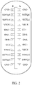
- the first Type-C interface is connected to a converter, and as shown in FIG. 2 , the first Type-C interface includes: a first group of pins and a second group of pins.
- the first group of pins may be connected to the earphone interface or the Type-C charging interface of the converter
- the second group of pins may be connected to the Type-C charging interface or the earphone interface of the converter.
- the first group of pins are connected to the earphone interface of the converter
- the second group of pins are connected to the Type-C charging interface of the converter.
- the second group of pins are connected to the earphone interface of the converter.
- the first group of pins include a first pin and a second pin
- the second group of pins include a third pin and a fourth pin; where the first pin is used as a first earphone pin and a first data transmission pin of the first Type-C interface, and the second pin is used as a second earphone pin and a second data transmission pin of the first Type-C interface.
- the third pin is used as a first earphone pin and a first data transmission pin of the first Type-C interface, and the fourth pin is used as a second earphone pin and a second data transmission pin of the first Type-C interface.
- the first group of pins are A6 and A7 pins of the first Type-C interface
- the second group of pins are B6 and B7 pins of the first Type-C interface
- the first group of pins may also be B6 and B7 pins
- the second group of pins may also be A6 and A7 pins.
- A6 is the first pin
- B6 is the third pin
- A6 and B6 are both used as the first earphone pin and the first data transmission pin of the first Type-C interface and specifically are DP/R pin
- A7 is the second pin
- B7 is the fourth pin
- A7 and B7 are both used as the second earphone pin and the second data transmission pin of the first Type-C interface and specifically are DN/L pin. That is, the first earphone pin (Rpin) is used as the first data transmission pin (DPpin), and the second earphone pin (Lpin) is used as the second data transmission pin (DNpin).
- A6, A7, B6, and B7 pins output digital audio signals.
- A6, A7, B6, and B7 pins transmit USB signals and enter the fast charging mode.
- the earphone interface is a 3.5 mm earphone interface.
- the first group of pins are connected to an application processor earphone interface or an application processor fast charge interface of the terminal device through the first switch unit.
- the second group of pins are connected to the application processor earphone interface or the application processor fast charge interface of the terminal device through the second switch unit.
- the application processor earphone interface includes an R pin and an L pin.
- the application processor fast charging interface can be used for fast charging through related fast charging protocols.
- the controller determines that the first group of pins are connected to the earphone interface of the converter, controls the first switch unit to connect the first group of pins to the application processor earphone interface, and controls the second switch unit to connect the second group of pins to the application processor fast charge interface; or when the grounding impedance value of the second group of pins is within the preset range, determines that the second group of pins are connected to the earphone interface of the converter, controls the second switch unit to connect the second group of pins to the application processor earphone interface, and controls the first switch unit to connect the first group of pins to the application processor fast charge interface.
- the controller determines that the first group of pins are used as the earphone interface, controls the first switch unit to connect the first group of pins to the application processor earphone interface, determines that the second group of pins are used as the data transmission interface, and controls the second switch unit to connect the second group of pins to the application processor fast charge interface.
- the controller determines that the second group of pins are used as the earphone interface, controls the second switch unit to connect the second group of pins to the application processor earphone interface, determines that the first group of pins are used as the data transmission interface, and controls the first switch unit to connect the first group of pins to the application processor fast charge interface.
- a master control unit (master control unit, MCU) can perform fast charging according to the fast charge protocol
- a main control unit MCU can perform fast charging according to the fast charging protocol.
- the controller can be specifically a control module of an application processor (application processor, AP).
- a group of pins in the first group of pins and the second group of pins are first determined as the earphone pin, and then the remaining group of pins are used as the charging pin, so that the earphone function and the fast charging function can be implemented at the same time.
- the controller controls one of the first switch unit and the second switch unit to connect to the application processor earphone interface according to the grounding impedance values of the first group of pins or the second group of pins, and controls the remaining switch unit to connect to the application processor fast charge interface, so that users can also perform fast charging in fast charge mode while using the earphone function.
- the controller controls one of the first switch unit and the second switch unit to connect to the application processor earphone interface according to the grounding impedance values of the first group of pins or the second group of pins, and the remaining switch unit may connect to the application processor fast charge interface, so that users can also perform fast charging in fast charge mode while using the earphone function.
- the first switch unit includes a first switching switch and a second switching switch.
- the second switch unit includes a third switching switch and a fourth switching switch.
- the first switching switch (switch 01) is respectively connected to the second pin (A7 pin) of the first group of pins and the first earphone pin (R pin) of the application processor earphone interface, or the first switching switch is respectively connected to the second pin (A7 pin) of the first group of pins and the first data transmission pin (DP pin) of the application processor fast charge interface.
- the second switching switch (switch 02) is respectively connected to the first pin (A6 pin) of the first group of pins and the second earphone pin (L pin) of the application processor earphone interface, or the second switching switch is respectively connected to the first pin (A6 pin) of the first group of pins and the second data transmission pin (DN pin) of the application processor fast charge interface.
- the third switching switch (switch 03) is respectively connected to the fourth pin (B7 pin) of the second group of pins and the first earphone pin (R pin) of the application processor earphone interface, or the third switching switch is respectively connected to the fourth pin (B7 pin) of the second group of pins and the first data transmission pin (DP pin) of the application processor fast charge interface.
- the fourth switching switch (switch 04) is respectively connected to the third pin (B6 pin) of the second group of pins and the second earphone pin (L pin) of the application processor earphone interface, or the fourth switching switch is respectively connected to the third pin (B6 pin) of the second group of pins and the second data transmission pin (DN pin) of the application processor fast charge interface.
- the first switching switch, the second switching switch, the third switching switch, and the fourth switching switch are all single-pole double-throw switches;
- A6 pin and B7 pin of the first Type-C interface are separated and are connected to different switch units, and A7 pin and B6 pin are separated and are connected to different switch units.
- DP pin and R pin are separated and DN pin and L pin are separated.
- A6 and A7 are DP pin and DN pin respectively, and B6 and B7 are R pin and L pin respectively.
- A6 pin and A7 pin of the adapter are connected to A6 pin and A7 pin of a Type-C female socket (Type-C charging interface) of a one-to-two adapter cable (can also be connected to B6 pin and B7 pin of the female socket), and B6 and B7 of the one-to-two adapter are connected to R pin and L pin of the 3.5 mm earphone socket (earphone interface).
- Type-C female socket Type-C charging interface
- B6 and B7 of the one-to-two adapter are connected to R pin and L pin of the 3.5 mm earphone socket (earphone interface).
- CC1 pin and CC2 pin of the first Type-C interface are short-circuited to the ground.
- the mobile terminal detects through CC1 pin and CC2 pin to determine whether a slave device is an analog earphone. For example, if voltages of CC1 pin and CC2 pin are less than a preset voltage threshold, it is determined that the slave device is an analog earphone device. Grounding impedances of A6 pin, A7 pin, B6 pin, and B7 pin are detected, and if the grounding impedances are within the preset range, it is determined that it is the earphone type.
- the switch is controlled to switch to a corresponding channel, that is, A6 and A7 pins are connected to the application processor earphone interface of the terminal device. If the impedances of B6 and B7 pins are outside the preset range, it is determined that it is the USB type, and the switch is controlled to switch to a corresponding channel, that is, B6 and B7 pins are connected to the application processor fast charge interface, and an earphone type channel is switched to earphone output and a USB type channel is switched to a USB channel.
- the charger performs VBUS charging on the mobile terminal. After the mobile terminal detects the VBUS charging, the mobile terminal starts fast charging protocol charging to perform fast charging and earphone functions.
- an embodiment of the present disclosure further provides an adapter, including: a second Type-C interface, and an earphone interface and a Type-C charging interface that are connected to the second Type-C interface.
- the earphone interface is specifically a 3.5 mm earphone interface, and the earphone is connected through the earphone interface.
- the Type-C charging interface is used to connect to the charger, and fast charging can be achieved through the Type-C charging interface.
- the earphone pin is connected to the earphone interface
- the data transmission pin is connected to the Type-C charging interface
- the second Type-C interface is connected to the terminal device
- the second Type-C interface includes the earphone pin and the data transmission pin.
- the earphone pin is connected to the first group of pins of the terminal device, and the data transmission pin is connected to the second group of pins of the terminal device; or the earphone pin is connected to the second group of pins of the terminal device, and the data transmission pin is connected to the first group of pins of the terminal device.
- the earphone pin includes: a first earphone pin (R pin) and a second earphone pin (L pin), and the data transmission pin includes a first data transmission pin (DP pin) and a second data transmission pin (DN pin).
- the second Type-C interface is specifically a Type-C male socket used to connect to the terminal device, and the first Type-C interface is specifically a Type-C female socket that is connected to the adapter.
- the first group of pins are specifically A6 and A7 pins of the first Type-C interface of the terminal device, and the second group of pins are specifically B6 and B7 pins of the first Type-C interface.
- the first group of pins can also be B6 and B7 pins of the first Type-C interface, and the second group of pins are A6 and A7 pins of the first Type-C interface.
- the first earphone pin and the second earphone pin are connected to two pins of the first group of pins in a one-to-one correspondence, and the first data transmission pin and the second data transmission pin are connected to two pins of the second group of pins in a one-to-one correspondence.
- the first earphone pin and the second earphone pin are connected to two pins of the second group of pins in a one-to-one correspondence, and the first data transmission pin and the second data transmission pin are connected to two pins of the first group of pins in a one-to-one correspondence.
- R pin is connected to R pin
- L pin is connected to L pin
- DP pin is connected to DP pin
- DN pin is connected to DN pin.
- the first data transmission pin (DP pin) and the first earphone pin (R pin) of the second Type-C interface are separated, and the second data transmission pin (DN pin) and the first earphone pin (L pin) are separated.
- DP and DN pins are connected to the Type-C charging interface, and R pin and L pin are connected to the earphone interface.
- A6 pin and B7 pin of the first Type-C interface of the terminal device are separated and are connected to different switch units, and A7 pin and B6 pin are separated and are connected to different switch units, so that the terminal device can achieve the fast charging function and the earphone function at the same time.
- Type-C charging interface includes: a first data transmission pin and a second data transmission pin.
- the first data transmission pin of the Type-C charging interface is connected to the first data transmission pin of the second Type-C interface.
- the second data transmission pin of the Type-C charging interface is connected to the second data transmission pin of the second Type-C interface.
- the first earphone pin of the earphone interface is connected to the first earphone pin of the second Type-C interface.
- the second earphone pin of the earphone interface is connected to the second earphone pin of the second Type-C interface.
- DP pin of the Type-C charging interface is connected to DP pin of the second Type-C interface
- DN pin of the Type-C charging interface is connected to DN pin of the second Type-C interface
- R pin of the earphone interface is connected to R pin of the second Type-C interface
- L pin of the earphone interface is connected to L pin of the second Type-C interface.
- DP pin and R pin of the second Type-C interface of the adapter are separated, and DN and L pin are separated.
- A6 and A7 pins of the adapter are DP and DN pins respectively, and B6 and B7 pins are R and L pins respectively.
- A6 and A7 pins of the adapter are connected to A6 and A7 pins of the Type-C female socket (Type-C charging interface) of the one-to-two adapter cable (can also be connected to B6 and B7 pins of the female socket), and B6 and B7 of the one-to-two adapter are connected to R and L pins of the 3.5 mm earphone socket (earphone interface).
- An embodiment of the present disclosure further provides a charging method, applied to the foregoing terminal device. As shown in FIG. 3 , the charging method includes:
- Step 301 Detect a grounding impedance value of a target pin, to obtain a detection result, where the target pin includes a first group of pins and/or a second group of pins.
- the terminal device is connected to the adapter, and this step may specifically include: detecting whether an external device connected to the adapter is an earphone device; and when the external device connected to the adapter is an earphone device, detecting a grounding impedance value of a target pin, to obtain a detection result, where the target pin includes a first group of pins and/or a second group of pins.
- the terminal device includes an application processor AP control module, an AP earphone interface (including R pin and L pin), an AP USB interface (including DP pin and DN pin), a switch module (a first switch unit and a second switch unit), and a first Type-C interface.
- the first Type-C interface is connected to a one-to-two adapter, and the one-to-two adapter is connected to a charger and a 3.5 mm earphone.
- the AP control module is responsible for detecting CC logic, determining an inserted device, and controlling switching of a state of the switch module, or the like.
- the AP earphone interface outputs an analog earphone signal and is usually a codec.
- the AP USB interface is a transmission charging protocol interface.
- the switch module is responsible for switching between left and right channel output and a USB port of the earphone.
- the AP control module pulls CC1 pin and CC2 pin to ground. After pulling CC1 pin and CC2 pin to ground, the resistance is less than Ra and is generally 1.2K. If voltages of CC1 pin and CC2 pin are less than a preset voltage threshold, it is determined that the external device is the earphone device; otherwise, it is determined that the external device is another device.
- Step 302 When the detection result is that the grounding impedance value of the first group of pins is within a preset range, control the first group of pins to connect to the application processor earphone interface of the terminal device, and control the second group of pins to connect to the application processor fast charge interface of the terminal device.
- the first switch unit is controlled to connect the first group of pins to the application processor earphone interface
- the second switch unit is controlled to connect the second group of pins to the application processor fast charge interface.
- Step 303 When the detection result is that the grounding impedance value of the second group of pins is within the preset range, control the second group of pins to connect to the application processor earphone interface, and control the first group of pins to connect to the application processor fast charge interface.
- the second switch unit is controlled to connect the second group of pins to the application processor earphone interface
- the first switch unit is controlled to connect the first group of pins to the application processor fast charge interface
- step 302 and step 303 are in parallel.
- the external device connected to the adapter is an earphone device; when the external device is an earphone device, a grounding impedance value of a target pin is detected, to obtain a detection result, where the target pin includes a first group of pins and/or a second group of pins.
- the detection result is that the grounding impedance value of the first group of pins is within a preset range
- the first group of pins are controlled to connect to the application processor earphone interface of the terminal device
- the second group of pins are controlled to connect to the application processor fast charge interface of the terminal device
- the detection result is that the grounding impedance value of the second group of pins is within the preset range
- users can also perform fast charging in fast charging mode while using the earphone function.
- the terminal device in the embodiments of this disclosure includes a device formed by components such as a radio frequency unit, a network module, an audio output unit, an input unit, a sensor, a display unit, a user input unit, an interface unit, a memory, a processor, and a power supply.
- a radio frequency unit such as a radio frequency unit, a network module, an audio output unit, an input unit, a sensor, a display unit, a user input unit, an interface unit, a memory, a processor, and a power supply.
Landscapes
- Engineering & Computer Science (AREA)
- Theoretical Computer Science (AREA)
- Physics & Mathematics (AREA)
- General Engineering & Computer Science (AREA)
- General Physics & Mathematics (AREA)
- Power Engineering (AREA)
- Acoustics & Sound (AREA)
- Signal Processing (AREA)
- Computer Hardware Design (AREA)
- Charge And Discharge Circuits For Batteries Or The Like (AREA)
- Telephone Function (AREA)
Abstract
Description
- This application claims priority to
Chinese Patent Application No. 201811593365.4 filed in China on December 25, 2018 - The embodiments of the present disclosure relate to the field of communications technologies, and in particular, to a terminal device, an adapter, and a charging method.
- Type-C interfaces of mobile terminals have gradually become popular. At the same time, the removal of 3.5 mm interfaces has become a trend. A Type-C interface needs to output digital audio and analog audio, and also needs to meet the charging needs. The way to output digital audio is that a digital-to-analog conversion chip and an earphone power amplifier chip are placed on an earphone, where the earphone is called a digital earphone, or a Type-C interface to a 3.5 mm interface adapter cable is used, a digital-to-analog conversion chip and an earphone power amplifier chip are placed on the adapter cable, and the 3.5 mm interface can be connected to a 3.5 mm analog earphone. The digital earphone completely occupies the Type-C interface and charging cannot be performed, and earphones popular on the market mostly use the 3.5 mm interface.
- When there is only Type-C interface and there is no 3.5 mm earphone interface, performing charging and earphone functions simultaneously requires a one-to-two adapter. This solution is ordinary charging and the charging speed is slow. Various fast charging methods commonly used need to occupy D+ and D- pins of the interface, and an audio output left channel L pin and an audio output right channel R pin of the earphone are generally used as these two pins. As a result, when the earphone function is used, the fast charge mode cannot be used, which affects user experience.
- The purpose of the present disclosure is to provide a terminal device, an adapter, and a charging method, to solve the problem that the charging speed is slow when a mobile terminal with a Type-C interface implements a charging function and an earphone function simultaneously through a one-to-two adapter.
- To solve the foregoing technical problem, embodiments of this disclosure are implemented as follows:
- According to a first aspect, an embodiment of the present disclosure provides a terminal device, including:
- a first Type-C interface, where the first Type-C interface includes: a first group of pins and a second group of pins;
- a first switch unit, where the first group of pins are connected to an application processor earphone interface or an application processor fast charge interface of the terminal device through the first switch unit;
- a second switch unit, where the second group of pins are connected to the application processor earphone interface or the application processor fast charge interface of the terminal device through the second switch unit; and
- a controller, where when the grounding impedance value of the first group of pins is within a preset range, the controller controls the first switch unit to connect the first group of pins to the application processor earphone interface, and controls the second switch unit to connect the second group of pins to the application processor fast charge interface;
- or when the grounding impedance value of the second group of pins is within the preset range, controls the second switch unit to connect the second group of pins to the application processor earphone interface, and controls the first switch unit to connect the first group of pins to the application processor fast charge interface.
- According to a second aspect, an embodiment of the present disclosure further provides an adapter, including:
- a second Type-C interface, where the second Type-C interface includes an earphone pin and a data transmission pin; and
- an earphone interface and a Type-C charging interface that are connected to the second Type-C interface, where the earphone pin is connected to the earphone interface, and the data transmission pin is connected to the Type-C charging interface;
- where the earphone pin is connected to the first group of pins of the terminal device, and the data transmission pin is connected to the second group of pins of the terminal device;
- or the earphone pin is connected to the second group of pins of the terminal device, and the data transmission pin is connected to the first group of pins of the terminal device.
- According to a third aspect, an embodiment of the present disclosure further provides a charging method, applied to the foregoing terminal device. The charging method includes:
- detecting a grounding impedance value of a target pin, to obtain a detection result, where the target pin includes a first group of pins and/or a second group of pins; and
- when the detection result is that the grounding impedance value of the first group of pins is within a preset range, controlling the first group of pins to connect to the application processor earphone interface of the terminal device, and controlling the second group of pins to connect to the application processor fast charge interface of the terminal device;
- or when the detection result is that the grounding impedance value of the second group of pins is within the preset range, controlling the second group of pins to connect to the application processor earphone interface, and controlling the first group of pins to connect to the application processor fast charge interface.
- The embodiments of this disclosure have the following beneficial effects:
- According to the above technical solutions of the embodiments of the present disclosure, the controller controls one of the first switch unit and the second switch unit to connect to the application processor earphone interface according to the grounding impedance values of the first group of pins or the second group of pins, and controls the remaining switch unit to connect to the application processor fast charge interface, so that users can also perform fast charging in fast charge mode while using the earphone function.
- To describe the technical solutions in the embodiments of the present disclosure more clearly, the following briefly describes the accompanying drawings required in the embodiments of the present disclosure. Apparently, the accompanying drawings in the following descriptions show merely some embodiments of the present disclosure, and a person of ordinary skill in the art may still derive other drawings from these accompanying drawings without creative efforts.
-
FIG. 1 is a schematic structural diagram of a terminal device and an adapter according to an embodiment of the present disclosure; -
FIG. 2 is a schematic structural diagram of a first Type-C interface of a terminal device according to an embodiment of this disclosure; -
FIG. 3 is a schematic flowchart of a charging method according to an embodiment of the present disclosure; and -
FIG. 4 is a schematic diagram of connection of a terminal device, an adapter, a charger, and an earphone according to an embodiment of the present disclosure. - The following clearly and completely describes the technical solutions in the embodiments of the present disclosure with reference to the accompanying drawings in the embodiments of the present disclosure. Apparently, the described embodiments are some but not all of the embodiments of the present disclosure. All other embodiments obtained by a person of ordinary skill in the art based on the embodiments of the present disclosure without creative efforts shall fall within the protection scope of the present disclosure.
- On the mobile terminal in the related technology and the one-to-two adapter (switching between charging and earphone functions), a DP pin and a DN pin are occupied by an L pin and an R pin respectively. As a result, when the earphone is used, only ordinary voltage bus (voltage bus, VBUS) charging can be used and the fast charging mode cannot be used, and charging cannot be controlled, affecting security.
- On this basis, an embodiment of the present disclosure provides a terminal device. As shown in
FIG. 1 , the terminal device includes: a first Type-C interface, a first switch unit, a second switch unit, and a controller. - The first Type-C interface is connected to a converter, and as shown in
FIG. 2 , the first Type-C interface includes: a first group of pins and a second group of pins. The first group of pins may be connected to the earphone interface or the Type-C charging interface of the converter, and the second group of pins may be connected to the Type-C charging interface or the earphone interface of the converter. When the first group of pins are connected to the earphone interface of the converter, the second group of pins are connected to the Type-C charging interface of the converter. When the first group of pins are connected to the Type-C charging interface of the converter, the second group of pins are connected to the earphone interface of the converter. - The first group of pins include a first pin and a second pin, the second group of pins include a third pin and a fourth pin; where the first pin is used as a first earphone pin and a first data transmission pin of the first Type-C interface, and the second pin is used as a second earphone pin and a second data transmission pin of the first Type-C interface. The third pin is used as a first earphone pin and a first data transmission pin of the first Type-C interface, and the fourth pin is used as a second earphone pin and a second data transmission pin of the first Type-C interface.
- For example, the first group of pins are A6 and A7 pins of the first Type-C interface, and the second group of pins are B6 and B7 pins of the first Type-C interface. Certainly, the first group of pins may also be B6 and B7 pins, and the second group of pins may also be A6 and A7 pins.
- A6 is the first pin, B6 is the third pin, and A6 and B6 are both used as the first earphone pin and the first data transmission pin of the first Type-C interface and specifically are DP/R pin. A7 is the second pin, B7 is the fourth pin, and A7 and B7 are both used as the second earphone pin and the second data transmission pin of the first Type-C interface and specifically are DN/L pin. That is, the first earphone pin (Rpin) is used as the first data transmission pin (DPpin), and the second earphone pin (Lpin) is used as the second data transmission pin (DNpin). When the first Type-C interface shown in
FIG. 2 is plugged into a digital earphone, A6, A7, B6, and B7 pins output digital audio signals. When the first Type-C interface shown inFIG. 2 is plugged into a universal serial bus (universal serial bus, USB) charger, A6, A7, B6, and B7 pins transmit USB signals and enter the fast charging mode. The earphone interface is a 3.5 mm earphone interface. - The first group of pins are connected to an application processor earphone interface or an application processor fast charge interface of the terminal device through the first switch unit.
- The second group of pins are connected to the application processor earphone interface or the application processor fast charge interface of the terminal device through the second switch unit.
- The application processor earphone interface includes an R pin and an L pin. The application processor fast charging interface can be used for fast charging through related fast charging protocols.
- When the grounding impedance value of the first group of pins is within a preset range, the controller determines that the first group of pins are connected to the earphone interface of the converter, controls the first switch unit to connect the first group of pins to the application processor earphone interface, and controls the second switch unit to connect the second group of pins to the application processor fast charge interface;
or when the grounding impedance value of the second group of pins is within the preset range, determines that the second group of pins are connected to the earphone interface of the converter, controls the second switch unit to connect the second group of pins to the application processor earphone interface, and controls the first switch unit to connect the first group of pins to the application processor fast charge interface. - Herein, when the grounding impedance value of the first group of pins is within a preset range, the controller determines that the first group of pins are used as the earphone interface, controls the first switch unit to connect the first group of pins to the application processor earphone interface, determines that the second group of pins are used as the data transmission interface, and controls the second switch unit to connect the second group of pins to the application processor fast charge interface.
- When the grounding impedance value of the second group of pins is within the preset range, the controller determines that the second group of pins are used as the earphone interface, controls the second switch unit to connect the second group of pins to the application processor earphone interface, determines that the first group of pins are used as the data transmission interface, and controls the first switch unit to connect the first group of pins to the application processor fast charge interface.
- When connecting the first group of pins to the application processor fast charge interface, a master control unit (master control unit, MCU) can perform fast charging according to the fast charge protocol, and when connecting the second group of pins to the application processor fast charge interface, a main control unit MCU can perform fast charging according to the fast charging protocol. The controller can be specifically a control module of an application processor (application processor, AP).
- For the terminal device of the embodiments of the present disclosure, a group of pins in the first group of pins and the second group of pins are first determined as the earphone pin, and then the remaining group of pins are used as the charging pin, so that the earphone function and the fast charging function can be implemented at the same time.
- According to the embodiments of the present disclosure, the controller controls one of the first switch unit and the second switch unit to connect to the application processor earphone interface according to the grounding impedance values of the first group of pins or the second group of pins, and controls the remaining switch unit to connect to the application processor fast charge interface, so that users can also perform fast charging in fast charge mode while using the earphone function.
- According to the terminal device of the embodiments of the present disclosure, the controller controls one of the first switch unit and the second switch unit to connect to the application processor earphone interface according to the grounding impedance values of the first group of pins or the second group of pins, and the remaining switch unit may connect to the application processor fast charge interface, so that users can also perform fast charging in fast charge mode while using the earphone function.
- Further, the first switch unit includes a first switching switch and a second switching switch.
- The second switch unit includes a third switching switch and a fourth switching switch.
- The first switching switch (switch 01) is respectively connected to the second pin (A7 pin) of the first group of pins and the first earphone pin (R pin) of the application processor earphone interface, or the first switching switch is respectively connected to the second pin (A7 pin) of the first group of pins and the first data transmission pin (DP pin) of the application processor fast charge interface.
- The second switching switch (switch 02) is respectively connected to the first pin (A6 pin) of the first group of pins and the second earphone pin (L pin) of the application processor earphone interface, or the second switching switch is respectively connected to the first pin (A6 pin) of the first group of pins and the second data transmission pin (DN pin) of the application processor fast charge interface.
- The third switching switch (switch 03) is respectively connected to the fourth pin (B7 pin) of the second group of pins and the first earphone pin (R pin) of the application processor earphone interface, or the third switching switch is respectively connected to the fourth pin (B7 pin) of the second group of pins and the first data transmission pin (DP pin) of the application processor fast charge interface.
- The fourth switching switch (switch 04) is respectively connected to the third pin (B6 pin) of the second group of pins and the second earphone pin (L pin) of the application processor earphone interface, or the fourth switching switch is respectively connected to the third pin (B6 pin) of the second group of pins and the second data transmission pin (DN pin) of the application processor fast charge interface.
- Specifically, the first switching switch, the second switching switch, the third switching switch, and the fourth switching switch are all single-pole double-throw switches;
- a non-movable port of the first switching switch is connected to the second pin of the first group of pins, and a movable port of the first switching switch is connected to the first earphone pin of the application processor earphone interface or the first data transmission pin of the application processor fast charge interface;
- a non-movable port of the second switching switch is connected to the first pin of the first group of pins, and a movable port of the second switching switch is connected to the second earphone pin of the application processor earphone interface or the second data transmission pin of the application processor fast charge interface;
- a non-movable port of the third switching switch is connected to the fourth pin of the second group of pins, and a movable port of the third switching switch is connected to the first earphone pin of the application processor earphone interface or the first data transmission pin of the application processor fast charge interface; and
- a non-movable port of the fourth switching switch is connected to the third pin of the second group of pins, and a movable port of the fourth switching switch is connected to the second earphone pin of the application processor earphone interface or the second data transmission pin of the application processor fast charge interface.
- In the terminal device of the embodiments of the present disclosure, A6 pin and B7 pin of the first Type-C interface are separated and are connected to different switch units, and A7 pin and B6 pin are separated and are connected to different switch units. Correspondingly, in the adapter, DP pin and R pin are separated and DN pin and L pin are separated. A6 and A7 are DP pin and DN pin respectively, and B6 and B7 are R pin and L pin respectively. A6 pin and A7 pin of the adapter are connected to A6 pin and A7 pin of a Type-C female socket (Type-C charging interface) of a one-to-two adapter cable (can also be connected to B6 pin and B7 pin of the female socket), and B6 and B7 of the one-to-two adapter are connected to R pin and L pin of the 3.5 mm earphone socket (earphone interface).
- In the embodiments of the present disclosure, after the 3.5 mm analog earphone and the charger are inserted into the terminal device through the adapter, CC1 pin and CC2 pin of the first Type-C interface are short-circuited to the ground. The mobile terminal detects through CC1 pin and CC2 pin to determine whether a slave device is an analog earphone. For example, if voltages of CC1 pin and CC2 pin are less than a preset voltage threshold, it is determined that the slave device is an analog earphone device. Grounding impedances of A6 pin, A7 pin, B6 pin, and B7 pin are detected, and if the grounding impedances are within the preset range, it is determined that it is the earphone type. For example, if it is detected that grounding impedances of A6 and A7 pins are within the preset range, it is determined that it is the earphone type, and the switch is controlled to switch to a corresponding channel, that is, A6 and A7 pins are connected to the application processor earphone interface of the terminal device. If the impedances of B6 and B7 pins are outside the preset range, it is determined that it is the USB type, and the switch is controlled to switch to a corresponding channel, that is, B6 and B7 pins are connected to the application processor fast charge interface, and an earphone type channel is switched to earphone output and a USB type channel is switched to a USB channel. The charger performs VBUS charging on the mobile terminal. After the mobile terminal detects the VBUS charging, the mobile terminal starts fast charging protocol charging to perform fast charging and earphone functions.
- As shown in
FIG. 1 , an embodiment of the present disclosure further provides an adapter, including:
a second Type-C interface, and an earphone interface and a Type-C charging interface that are connected to the second Type-C interface. - The earphone interface is specifically a 3.5 mm earphone interface, and the earphone is connected through the earphone interface. The Type-C charging interface is used to connect to the charger, and fast charging can be achieved through the Type-C charging interface.
- The earphone pin is connected to the earphone interface, the data transmission pin is connected to the Type-C charging interface, the second Type-C interface is connected to the terminal device, and the second Type-C interface includes the earphone pin and the data transmission pin.
- The earphone pin is connected to the first group of pins of the terminal device, and the data transmission pin is connected to the second group of pins of the terminal device;
or the earphone pin is connected to the second group of pins of the terminal device, and the data transmission pin is connected to the first group of pins of the terminal device. - Specifically, the earphone pin includes: a first earphone pin (R pin) and a second earphone pin (L pin), and the data transmission pin includes a first data transmission pin (DP pin) and a second data transmission pin (DN pin). The second Type-C interface is specifically a Type-C male socket used to connect to the terminal device, and the first Type-C interface is specifically a Type-C female socket that is connected to the adapter.
- The first group of pins are specifically A6 and A7 pins of the first Type-C interface of the terminal device, and the second group of pins are specifically B6 and B7 pins of the first Type-C interface. Certainly, the first group of pins can also be B6 and B7 pins of the first Type-C interface, and the second group of pins are A6 and A7 pins of the first Type-C interface.
- The first earphone pin and the second earphone pin are connected to two pins of the first group of pins in a one-to-one correspondence, and the first data transmission pin and the second data transmission pin are connected to two pins of the second group of pins in a one-to-one correspondence. Alternatively, the first earphone pin and the second earphone pin are connected to two pins of the second group of pins in a one-to-one correspondence, and the first data transmission pin and the second data transmission pin are connected to two pins of the first group of pins in a one-to-one correspondence.
- Specifically, R pin is connected to R pin, L pin is connected to L pin, DP pin is connected to DP pin, and DN pin is connected to DN pin.
- In the adapter of the embodiments of the present disclosure, the first data transmission pin (DP pin) and the first earphone pin (R pin) of the second Type-C interface are separated, and the second data transmission pin (DN pin) and the first earphone pin (L pin) are separated. DP and DN pins are connected to the Type-C charging interface, and R pin and L pin are connected to the earphone interface. Correspondingly, A6 pin and B7 pin of the first Type-C interface of the terminal device are separated and are connected to different switch units, and A7 pin and B6 pin are separated and are connected to different switch units, so that the terminal device can achieve the fast charging function and the earphone function at the same time.
- Further, the Type-C charging interface includes: a first data transmission pin and a second data transmission pin.
- The first data transmission pin of the Type-C charging interface is connected to the first data transmission pin of the second Type-C interface.
- The second data transmission pin of the Type-C charging interface is connected to the second data transmission pin of the second Type-C interface.
- The first earphone pin of the earphone interface is connected to the first earphone pin of the second Type-C interface.
- The second earphone pin of the earphone interface is connected to the second earphone pin of the second Type-C interface.
- As shown in
FIG. 1 , DP pin of the Type-C charging interface is connected to DP pin of the second Type-C interface, DN pin of the Type-C charging interface is connected to DN pin of the second Type-C interface, R pin of the earphone interface is connected to R pin of the second Type-C interface, and L pin of the earphone interface is connected to L pin of the second Type-C interface. - In the embodiments of the present disclosure, DP pin and R pin of the second Type-C interface of the adapter are separated, and DN and L pin are separated. A6 and A7 pins of the adapter are DP and DN pins respectively, and B6 and B7 pins are R and L pins respectively. A6 and A7 pins of the adapter are connected to A6 and A7 pins of the Type-C female socket (Type-C charging interface) of the one-to-two adapter cable (can also be connected to B6 and B7 pins of the female socket), and B6 and B7 of the one-to-two adapter are connected to R and L pins of the 3.5 mm earphone socket (earphone interface).
- An embodiment of the present disclosure further provides a charging method, applied to the foregoing terminal device. As shown in
FIG. 3 , the charging method includes: - Step 301: Detect a grounding impedance value of a target pin, to obtain a detection result, where the target pin includes a first group of pins and/or a second group of pins.
- In the embodiments of the present disclosure, the terminal device is connected to the adapter, and this step may specifically include: detecting whether an external device connected to the adapter is an earphone device; and when the external device connected to the adapter is an earphone device, detecting a grounding impedance value of a target pin, to obtain a detection result, where the target pin includes a first group of pins and/or a second group of pins.
- As shown in
FIG. 4 , in the embodiments of the present disclosure, the terminal device includes an application processor AP control module, an AP earphone interface (including R pin and L pin), an AP USB interface (including DP pin and DN pin), a switch module (a first switch unit and a second switch unit), and a first Type-C interface. The first Type-C interface is connected to a one-to-two adapter, and the one-to-two adapter is connected to a charger and a 3.5 mm earphone. - The AP control module is responsible for detecting CC logic, determining an inserted device, and controlling switching of a state of the switch module, or the like.
- The AP earphone interface outputs an analog earphone signal and is usually a codec.
- The AP USB interface is a transmission charging protocol interface.
- The switch module is responsible for switching between left and right channel output and a USB port of the earphone.
- Specifically, the AP control module pulls CC1 pin and CC2 pin to ground. After pulling CC1 pin and CC2 pin to ground, the resistance is less than Ra and is generally 1.2K. If voltages of CC1 pin and CC2 pin are less than a preset voltage threshold, it is determined that the external device is the earphone device; otherwise, it is determined that the external device is another device.
- Step 302: When the detection result is that the grounding impedance value of the first group of pins is within a preset range, control the first group of pins to connect to the application processor earphone interface of the terminal device, and control the second group of pins to connect to the application processor fast charge interface of the terminal device.
- Specifically, the first switch unit is controlled to connect the first group of pins to the application processor earphone interface, and the second switch unit is controlled to connect the second group of pins to the application processor fast charge interface.
- Step 303: When the detection result is that the grounding impedance value of the second group of pins is within the preset range, control the second group of pins to connect to the application processor earphone interface, and control the first group of pins to connect to the application processor fast charge interface.
- Specifically, the second switch unit is controlled to connect the second group of pins to the application processor earphone interface, and the first switch unit is controlled to connect the first group of pins to the application processor fast charge interface.
- The foregoing
step 302 and step 303 are in parallel. - In the technical solutions of the embodiments of the present disclosure, by changing the peripheral circuit structure of the Type-C interface of the mobile terminal, adding electronic switches, separating a Type-C earphone (L/R) channel and a USB (DP/DN) channel, and designing reasonable system logic, users can achieve the fast charging function and the earphone function at the same time after inserting a related device.
- In the charging method of the embodiments of the present disclosure, it is detected whether the external device connected to the adapter is an earphone device; when the external device is an earphone device, a grounding impedance value of a target pin is detected, to obtain a detection result, where the target pin includes a first group of pins and/or a second group of pins. When the detection result is that the grounding impedance value of the first group of pins is within a preset range, it is determined that the first group of pins are connected to the earphone interface of the converter, the first group of pins are controlled to connect to the application processor earphone interface of the terminal device, and the second group of pins are controlled to connect to the application processor fast charge interface of the terminal device; or when the detection result is that the grounding impedance value of the second group of pins is within the preset range, it is determined that the second group of pins are connected to the earphone interface of the converter, the second group of pins are controlled to connect to the application processor earphone interface, and the first group of pins are controlled to connect to the application processor fast charge interface. In this way, users can also perform fast charging in fast charging mode while using the earphone function.
- The terminal device in the embodiments of this disclosure includes a device formed by components such as a radio frequency unit, a network module, an audio output unit, an input unit, a sensor, a display unit, a user input unit, an interface unit, a memory, a processor, and a power supply.
- The embodiments in this specification are described in a progressive manner. Each embodiment focuses on a difference from another embodiment. For a same or similar part of the embodiments, refer to each other.
- Although some optional embodiments in the embodiments of this disclosure have been described, persons skilled in the art can make changes and modifications to these embodiments once they learn the basic inventive concept. Therefore, the following claims are intended to be construed as to cover optional embodiments and all changes and modifications falling within the scope of the embodiments of this disclosure.
- Finally, it should be noted that in this specification, relationship terms such as "first" and "second" are merely used to distinguish one entity or operation from another, and do not necessarily require or imply that any actual relationship or sequence exists between these entities or operations. Moreover, the terms "include", "comprise", or their any other variants are intended to cover a non-exclusive inclusion, so that a process, a method, an article, or a terminal device that includes a list of elements not only includes those elements but also includes other elements that are not listed, or further includes elements inherent to such a process, method, article, or terminal device. Without being subject to further limitations, an element defined by a phrase "including ......" does not exclude presence of other identical elements in the process, method, article, or terminal device that includes the very element.
- The foregoing descriptions are merely optional embodiments of this disclosure, but are not intended to limit this disclosure. Any modification, equivalent replacement, or improvement made without departing from the spirit and principle of this disclosure shall fall within the protection scope of this disclosure.
Claims (12)
- A terminal device, comprising:a first Type-C interface, wherein the first Type-C interface comprises: a first group of pins and a second group of pins;a first switch unit, wherein the first group of pins are connected to an application processor earphone interface or an application processor fast charge interface of the terminal device through the first switch unit;a second switch unit, wherein the second group of pins are connected to the application processor earphone interface or the application processor fast charge interface of the terminal device through the second switch unit; anda controller, wherein in a case where grounding impedance value of the first group of pins is within a preset range, the controller controls the first switch unit to connect the first group of pins to the application processor earphone interface, and controls the second switch unit to connect the second group of pins to the application processor fast charge interface;or in a case where grounding impedance value of the second group of pins is within the preset range, controls the second switch unit to connect the second group of pins to the application processor earphone interface, and controls the first switch unit to connect the first group of pins to the application processor fast charge interface.
- The terminal device according to claim 1, wherein the first group of pins comprise a first pin and a second pin, and the second group of pins comprise a third pin and a fourth pin;wherein the first pin is used as a first earphone pin and a first data transmission pin of the first Type-C interface, and the second pin is used as a second earphone pin and a second data transmission pin of the first Type-C interface; andthe third pin is used as a first earphone pin and a first data transmission pin of the first Type-C interface, and the fourth pin is used as a second earphone pin and a second data transmission pin of the first Type-C interface.
- The terminal device according to claim 2, whereinthe first switch unit comprises a first switching switch and a second switching switch;the second switch unit comprises a third switching switch and a fourth switching switch;wherein the first switching switch is respectively connected to the second pin and a first earphone pin of the application processor earphone interface, or the first switching switch is respectively connected to the second pin and a first data transmission pin of the application processor fast charge interface;the second switching switch is respectively connected to the first pin and a second earphone pin of the application processor earphone interface, or the second switching switch is respectively connected to the first pin and a second data transmission pin of the application processor fast charge interface;the third switching switch is respectively connected to the fourth pin and the first earphone pin of the application processor earphone interface, or the third switching switch is respectively connected to the fourth pin and the first data transmission pin of the application processor fast charge interface; andthe fourth switching switch is respectively connected to the third pin and the second earphone pin of the application processor earphone interface, or the fourth switching switch is respectively connected to the third pin and the second data transmission pin of the application processor fast charge interface.
- The terminal device according to claim 3, wherein the first switching switch, the second switching switch, the third switching switch, and the fourth switching switch are all single-pole double-throw switches;a non-movable port of the first switching switch is connected to the second pin, and a movable port of the first switching switch is connected to the first earphone pin of the application processor earphone interface or the first data transmission pin of the application processor fast charge interface;a non-movable port of the second switching switch is connected to the first pin, and a movable port of the second switching switch is connected to the second earphone pin of the application processor earphone interface or the second data transmission pin of the application processor fast charge interface;a non-movable port of the third switching switch is connected to the fourth pin, and a movable port of the third switching switch is connected to the first earphone pin of the application processor earphone interface or the first data transmission pin of the application processor fast charge interface; anda non-movable port of the fourth switching switch is connected to the third pin, and a movable port of the fourth switching switch is connected to the second earphone pin of the application processor earphone interface or the second data transmission pin of the application processor fast charge interface.
- An adapter, comprising:a second Type-C interface, wherein the second Type-C interface comprises an earphone pin and a data transmission pin; andan earphone interface and a Type-C charging interface that are connected to the second Type-C interface, wherein the earphone pin is connected to the earphone interface, and the data transmission pin is connected to the Type-C charging interface;wherein the earphone pin is connected to the first group of pins of a terminal device, and the data transmission pin is connected to the second group of pins of the terminal device;or the earphone pin is connected to the second group of pins of the terminal device, and the data transmission pin is connected to the first group of pins of the terminal device.
- The adapter according to claim 5, wherein the earphone pin comprises: a first earphone pin and a second earphone pin, and the data transmission pin comprises a first data transmission pin and a second data transmission pin.
- The adapter according to claim 6, wherein the first earphone pin and the second earphone pin are connected to two pins of the first group of pins in a one-to-one correspondence, and the first data transmission pin and the second data transmission pin are connected to two pins of the second group of pins in a one-to-one correspondence.
- The adapter according to claim 6, wherein the first earphone pin and the second earphone pin are connected to two pins of the second group of pins in a one-to-one correspondence, and the first data transmission pin and the second data transmission pin are connected to two pins of the first group of pins in a one-to-one correspondence.
- The adapter according to claim 6, wherein the first data transmission pin of the Type-C charging interface is connected to the first data transmission pin of the second Type-C interface; and
the second data transmission pin of the Type-C charging interface is connected to the second data transmission pin of the second Type-C interface. - The adapter according to claim 6, wherein the first earphone pin of the earphone interface is connected to the first earphone pin of the second Type-C interface; and
the second earphone pin of the earphone interface is connected to the second earphone pin of the second Type-C interface. - A charging method, applied to the terminal device according to any one of claims 1 to 4, comprising:detecting a grounding impedance value of a target pin, to obtain a detection result, wherein the target pin comprises a first group of pins and/or a second group of pins; andin a case where the detection result is that the grounding impedance value of the first group of pins is within a preset range, controlling the first group of pins to connect to the application processor earphone interface of the terminal device, and controlling the second group of pins to connect to the application processor fast charge interface of the terminal device;or in a case where the detection result is that the grounding impedance value of the second group of pins is within the preset range, controlling the second group of pins to connect to the application processor earphone interface, and controlling the first group of pins to connect to the application processor fast charge interface.
- The charging method according to claim 11, wherein the controlling the first group of pins to connect to the application processor earphone interface of the terminal device, and controlling the second group of pins to connect to the application processor fast charge interface of the terminal device comprises:controlling the first switch unit to connect the first group of pins to the application processor earphone interface, and controlling the second switch unit to connect the second group of pins to the application processor fast charge interface; andthe controlling the second group of pins to connect to the application processor earphone interface, and controlling the first group of pins to connect to the application processor fast charge interface comprises:
controlling the second switch unit to connect the second group of pins to the application processor earphone interface, and controlling the first switch unit to connect the first group of pins to the application processor fast charge interface.
Applications Claiming Priority (2)
| Application Number | Priority Date | Filing Date | Title |
|---|---|---|---|
| CN201811593365.4A CN109862457A (en) | 2018-12-25 | 2018-12-25 | Terminal equipment, adapter and charging method |
| PCT/CN2019/121219 WO2020134812A1 (en) | 2018-12-25 | 2019-11-27 | Terminal device, adapter, and charging method |
Publications (2)
| Publication Number | Publication Date |
|---|---|
| EP3905714A1 true EP3905714A1 (en) | 2021-11-03 |
| EP3905714A4 EP3905714A4 (en) | 2022-02-16 |
Family
ID=66892266
Family Applications (1)
| Application Number | Title | Priority Date | Filing Date |
|---|---|---|---|
| EP19904790.3A Pending EP3905714A4 (en) | 2018-12-25 | 2019-11-27 | TERMINAL DEVICE, ADAPTER AND CHARGING METHOD |
Country Status (4)
| Country | Link |
|---|---|
| US (1) | US11860805B2 (en) |
| EP (1) | EP3905714A4 (en) |
| CN (1) | CN109862457A (en) |
| WO (1) | WO2020134812A1 (en) |
Families Citing this family (8)
| Publication number | Priority date | Publication date | Assignee | Title |
|---|---|---|---|---|
| CN109862457A (en) | 2018-12-25 | 2019-06-07 | 维沃移动通信有限公司 | Terminal equipment, adapter and charging method |
| CN111130596B (en) | 2019-11-14 | 2021-08-03 | 荣耀终端有限公司 | A multiplexing circuit, interface circuit system and mobile terminal |
| CN111030219B (en) * | 2019-12-13 | 2021-09-17 | 深圳市普威技术有限公司 | But real-time communication's fill data line soon |
| CN112737566B (en) * | 2021-04-02 | 2021-06-22 | 荣耀终端有限公司 | Interface conversion circuit and electronic equipment |
| CN113660373B (en) * | 2021-10-19 | 2022-01-07 | 浙江地芯引力科技有限公司 | Charging authentication method, device, equipment and storage medium |
| CN115237841A (en) * | 2022-07-25 | 2022-10-25 | 维沃移动通信有限公司 | Electronic equipment, quick charging method, device, system and readable storage medium |
| CN117708012B (en) * | 2023-06-09 | 2024-11-05 | 荣耀终端有限公司 | Electronic devices |
| CN116742761B (en) * | 2023-08-10 | 2023-11-17 | 北京小米移动软件有限公司 | Charging method, charging device, electronic equipment and storage medium |
Family Cites Families (18)
| Publication number | Priority date | Publication date | Assignee | Title |
|---|---|---|---|---|
| CN205544514U (en) * | 2016-03-11 | 2016-08-31 | 深圳市普洛威电子有限公司 | Take DATA TRANSFER FUNCTIONS's integrated charger |
| CN106058553A (en) * | 2016-05-17 | 2016-10-26 | 乐视控股(北京)有限公司 | Adapter and double-surface magnetic type conversion assembly |
| KR102576430B1 (en) * | 2016-11-18 | 2023-09-08 | 삼성전자주식회사 | Apparatus for providing interface |
| CN108271093B (en) * | 2016-12-30 | 2019-12-17 | 维沃移动通信有限公司 | Access device processing method and mobile terminal |
| TWI611648B (en) * | 2017-01-18 | 2018-01-11 | 廣達電腦股份有限公司 | Bidirectional charge and discharge circuit architecture |
| CN106874233B (en) * | 2017-02-16 | 2018-10-19 | 维沃移动通信有限公司 | A kind of Type-C interface control circuits, control method and mobile terminal |
| CN108666826B (en) * | 2017-03-31 | 2020-06-23 | 中兴通讯股份有限公司 | Adapter, terminal equipment and adapter system |
| CN206758786U (en) * | 2017-04-25 | 2017-12-15 | 深圳市佰骏电子有限公司 | A kind of three-in-one external equipment of biphone converter with charge function |
| CN206908051U (en) * | 2017-04-27 | 2018-01-19 | 深圳市高普达科技有限公司 | The positive anti-plug formula power data docking station of double nip |
| CN107172515A (en) * | 2017-05-19 | 2017-09-15 | 青岛海信移动通信技术股份有限公司 | Test earphone plug is inserted in mobile terminal detection circuit and mobile terminal |
| US10579119B2 (en) * | 2017-05-23 | 2020-03-03 | Cirrus Logic, Inc. | Active charge through of a peripheral device |
| CN107204645B (en) * | 2017-06-09 | 2020-05-05 | 北京字节跳动网络技术有限公司 | A rechargeable portable device |
| CN107205189B (en) * | 2017-06-27 | 2019-11-08 | 芯海科技(深圳)股份有限公司 | One kind being based on TYPE-C handset module and recognition methods |
| CN207530591U (en) * | 2017-12-13 | 2018-06-22 | 郭亚飞 | A kind of charging unit of no charging jacks mobile phone |
| US20190286593A1 (en) * | 2018-03-16 | 2019-09-19 | Bose Corporation | Audio Signal Transmission |
| CN208272318U (en) * | 2018-04-23 | 2018-12-21 | 歌尔科技有限公司 | A kind of TYPE C interface patchcord |
| CN108810701B (en) * | 2018-06-27 | 2019-12-03 | 维沃移动通信有限公司 | A Type-C interface anomaly detection method and mobile terminal |
| CN109862457A (en) * | 2018-12-25 | 2019-06-07 | 维沃移动通信有限公司 | Terminal equipment, adapter and charging method |
-
2018
- 2018-12-25 CN CN201811593365.4A patent/CN109862457A/en active Pending
-
2019
- 2019-11-27 EP EP19904790.3A patent/EP3905714A4/en active Pending
- 2019-11-27 WO PCT/CN2019/121219 patent/WO2020134812A1/en not_active Ceased
-
2021
- 2021-06-21 US US17/352,908 patent/US11860805B2/en active Active
Also Published As
| Publication number | Publication date |
|---|---|
| US11860805B2 (en) | 2024-01-02 |
| EP3905714A4 (en) | 2022-02-16 |
| WO2020134812A1 (en) | 2020-07-02 |
| US20210314697A1 (en) | 2021-10-07 |
| CN109862457A (en) | 2019-06-07 |
Similar Documents
| Publication | Publication Date | Title |
|---|---|---|
| US11860805B2 (en) | Terminal device, adapter, and charging method | |
| US11526459B2 (en) | Adapter, terminal device and adapter system | |
| US11611221B2 (en) | Electronic device and accessory with quick charging and audio transmission functions | |
| US9904267B2 (en) | Method and apparatus for determining direction of power delivery | |
| EP2336895B1 (en) | Electronic device and method thereof for identifying electronic accessory | |
| CN101841586B (en) | Method for expanding earphone interface of mobile phone into serial communication interface | |
| JP2013109410A (en) | Determination circuit | |
| WO2008068311A2 (en) | Enhanced communication via a serial interface | |
| EP3018556B1 (en) | System for controlling peripherals connected to a docking station | |
| CN105635885A (en) | USB interface multiplex circuit, mobile terminal and earphone | |
| CN114281745B (en) | A docking station capable of switching to connect to multiple upstream hosts | |
| CN112492433B (en) | Charging box, wireless earphone and wireless earphone charging system | |
| JP7417767B2 (en) | Data cables and charging equipment | |
| CN106502939A (en) | A kind of USB adapters and data transmission set | |
| CN102201826B (en) | Audio signal switching and receiving device and audio signal transmission system | |
| CN212517830U (en) | Multifunctional switching device | |
| CN103813231A (en) | Method, intelligent device, system and plug for judging access signals | |
| CN210723605U (en) | Interface conversion device and converter | |
| EP4096033B1 (en) | State detection device for use in an audio interface | |
| CN112821156B (en) | Electronic tags chip and TYPE-C data line | |
| EP2383860B1 (en) | Rapid charging apparatus | |
| CN107706977A (en) | Method for detecting charging current and charging device | |
| EP3690633B1 (en) | Signal transmission circuit, signal transmission method and intelligent terminal | |
| CN207835731U (en) | A kind of earphone cradle | |
| CN208656444U (en) | Wireless headset charging box with mobile phone charging function |
Legal Events
| Date | Code | Title | Description |
|---|---|---|---|
| STAA | Information on the status of an ep patent application or granted ep patent |
Free format text: STATUS: THE INTERNATIONAL PUBLICATION HAS BEEN MADE |
|
| PUAI | Public reference made under article 153(3) epc to a published international application that has entered the european phase |
Free format text: ORIGINAL CODE: 0009012 |
|
| STAA | Information on the status of an ep patent application or granted ep patent |
Free format text: STATUS: REQUEST FOR EXAMINATION WAS MADE |
|
| 17P | Request for examination filed |
Effective date: 20210713 |
|
| AK | Designated contracting states |
Kind code of ref document: A1 Designated state(s): AL AT BE BG CH CY CZ DE DK EE ES FI FR GB GR HR HU IE IS IT LI LT LU LV MC MK MT NL NO PL PT RO RS SE SI SK SM TR |
|
| A4 | Supplementary search report drawn up and despatched |
Effective date: 20220118 |
|
| RIC1 | Information provided on ipc code assigned before grant |
Ipc: G06F 13/38 20060101ALI20220112BHEP Ipc: H01R 13/66 20060101ALI20220112BHEP Ipc: H01R 31/06 20060101ALI20220112BHEP Ipc: H02J 7/00 20060101ALI20220112BHEP Ipc: H04R 1/10 20060101AFI20220112BHEP |
|
| DAV | Request for validation of the european patent (deleted) | ||
| DAX | Request for extension of the european patent (deleted) | ||
| RAP1 | Party data changed (applicant data changed or rights of an application transferred) |
Owner name: NOKIA TECHNOLOGIES OY |