EP3905482B1 - Bidirectional wireless device - Google Patents
Bidirectional wireless device Download PDFInfo
- Publication number
- EP3905482B1 EP3905482B1 EP21171567.7A EP21171567A EP3905482B1 EP 3905482 B1 EP3905482 B1 EP 3905482B1 EP 21171567 A EP21171567 A EP 21171567A EP 3905482 B1 EP3905482 B1 EP 3905482B1
- Authority
- EP
- European Patent Office
- Prior art keywords
- field
- sensor
- identifying
- network
- node
- Prior art date
- Legal status (The legal status is an assumption and is not a legal conclusion. Google has not performed a legal analysis and makes no representation as to the accuracy of the status listed.)
- Active
Links
Images




Classifications
-
- H—ELECTRICITY
- H02—GENERATION; CONVERSION OR DISTRIBUTION OF ELECTRIC POWER
- H02J—ELECTRIC POWER NETWORKS; CIRCUIT ARRANGEMENTS OR SYSTEMS FOR SUPPLYING OR DISTRIBUTING ELECTRIC POWER; SYSTEMS FOR STORING ELECTRIC ENERGY
- H02J13/00—Circuit arrangements for providing remote monitoring or remote control of equipment in a power distribution network
- H02J13/13—Circuit arrangements for providing remote monitoring or remote control of equipment in a power distribution network characterised by the transmission of data to equipment in the power network
- H02J13/1337—Circuit arrangements for providing remote monitoring or remote control of equipment in a power distribution network characterised by the transmission of data to equipment in the power network involving the use of Internet protocols
-
- H—ELECTRICITY
- H02—GENERATION; CONVERSION OR DISTRIBUTION OF ELECTRIC POWER
- H02J—ELECTRIC POWER NETWORKS; CIRCUIT ARRANGEMENTS OR SYSTEMS FOR SUPPLYING OR DISTRIBUTING ELECTRIC POWER; SYSTEMS FOR STORING ELECTRIC ENERGY
- H02J13/00—Circuit arrangements for providing remote monitoring or remote control of equipment in a power distribution network
- H02J13/18—Circuit arrangements for providing remote monitoring or remote control of equipment in a power distribution network characterised by the remotely-controlled equipment, e.g. converters or transformers
- H02J13/34—Circuit arrangements for providing remote monitoring or remote control of equipment in a power distribution network characterised by the remotely-controlled equipment, e.g. converters or transformers the equipment being switches, relays or circuit breakers
Definitions
- a two-way wireless device is described according to claim 1.
- the two-way wireless device described hereinafter comprises at least one sensor and at least one actuator for regulating an electric load.
- the device described hereinafter can be used as a node, namely as a slave node, for a wireless network to regulate at least one electric load.
- a process for managing a wireless network having nodes with actuators for controlling an electric load, and sensors for generating control signals associated therewith, is also described according to claim 8.
- Preferred embodiments are described in the dependent claims.
- electric load comprises electric lamps.
- control devices and the various electric loads are connected to one another according to a functional diagram.
- any changes in the operation of a conventional power system require the wiring between the control devices (such as switches or sensors) and the electric loads to be also changed.
- control devices and actuator devices all the devices (i.e. control devices and actuator devices) have a shared connection for data exchange.
- the actuators are connected to a power line for supplying power to the electric loads.
- US 8 018 097 B2 discloses a switching control system of a circuit breaker which prevents transient phenomena that impact electric power systems and electric power equipment by controlling the opening or closing timing of the circuit breaker.
- the purpose of the inventor is to suggest a solution to at least partially solve the problems of the prior art.
- one purpose of the inventor is to provide an easy and cost-effective solution to design a commercial power system that can be easily adapted to users' needs.
- This purpose is achieved by of a two-way wireless device as described hereinafter, by a wireless network for regulating at least one electric load, whose nodes comprise a plurality of such two-way wireless devices and by a method for regulating at least one electric load as described hereinafter.
- a wireless network 10 with a proprietary transmission protocol may be designed, with a plurality n of slave nodes 1, 1 ,2 , 1 ,3 , .., 1 n , that are capable of direct or indirect transmit and receive communication, with a master node or gateway 11.
- the master node or gateway 11 of the network 10 may be connected to an Internet network, through a home Wi-Fi network.
- Every communication between the nodes 1, 1 2 , 1 3 , .., 1 n and the smartphone 15 passes through the master or gateway node 11.
- the wireless network 10 may be, for example, a point-to-multipoint wireless network (such as the one of Figure 2 ) or a mesh network.
- the n slave nodes of the network 10 can also operate as repeaters with one another (if one of the nodes 1 is not able to directly communicate with the master node 11.
- the wireless network 10 can be used, for example, to regulate at least one electric load 100, for example an electric lamp 100.
- the device 1 comprises a container 8 whose shape and size allow it to fit into a conventional wall-recessed box (e.g. the box typically known as "503 box”) or a conventional recessed junction box.
- a conventional wall-recessed box e.g. the box typically known as "503 box”
- a conventional recessed junction box e.g. the box typically known as "503 box”
- the container 8 comprises a first side, or front side 81, intended to be exposed, and a second side, or rear side, 82, intended to remain inside the box 80.
- the device 1 comprises a programmable processor 2, a radio-frequency transmitter 51, a radio-frequency receiver 52, at least one antenna 521, 522, at least one actuator 3, for regulating the power absorbed by an electric load, and at least one sensor 6, 9.
- sensor 6, 9 includes manually operable switches, for example touch-sensitive switches, in particular capacitive tactile sensors.
- the trigger 4 may be connected to the microcontroller 2 via a conventional bus 20, for example a conventional SPI bus 20.
- the TRIAC 31 may be used as an on/off switch or as a dimmer.
- the radio-frequency receiver 52 is designed to receive, from the network 10, second data packets P2 (or input data packets) addressed to the programmable processor 2.
- the data packets P1 and P2 may also comprise a field, located at the beginning of the data packet, which contains data packet synchronization bits and a field containing an error correcting code.
- the first data packets P1, or transmitted data packets have a format other than the format of the second data packets P2, or received data packets.
- At least one antenna 521, 522 is provided for transmission and reception of the data packets P1, P2 that are being sent to and received from the programmable processor 2.
- two distinct antennas 521, 522 are provided.
- a first antenna 521 is connected to the transmitter 51, for data transmission, and a second antenna 522 is connected to the receiver 52, for data reception.
- the radio frequency transmitter 51 and the radio frequency receiver 52 are adapted to operate in the UHF band.
- the transmitter 51 and the receiver 52 may be integrated in the same microchip that contains the microcontroller 2.
- the transmitter 51 may be a low power UHF transmitter (for example with an output power of up to 20 mWatt).
- the master node 11 is designed using a device 1 that differs from the devices 1 used for the slave nodes 1, 1 2 , 1 3 , .., 1 n , in the firmware (contained in the register 22).
- Each data packet P1 comprises a field C10 containing synchronization information for the network 10 and a field C11 identifying the sender node 1 I (and hence the device 1 that generated the packet).
- Each data packet P1 comprises a field C12 identifying at least one sensor 6, 9 and a field C13 representative of the state of the sensor.
- the data packets P2 that come from the master node 11 and are addressed to the microcontroller 2 of the device 1 comprise a field C20 containing synchronization information for the network 10, a field C21 identifying the receiver node 1 j , and hence the device 1 that is the receiver of the data packet P2, a field C22 identifying the actuator 3 associated with the receiver node 1 j (contained in the device 1 to which the data packet P2 is addressed) and a field C23 representative of a control signal for the actuator 3.
- the field C23 of the data packet P2 contains an on/off control signal to be sent to the trigger 4, which in turn controls the TRIAC 31.
- the generation of the control signals to be sent to the actuators 3 of the network 10 may be also remotely controlled, for example by means of the aforementioned smartphone application, available for download from the Internet and for installation on the smartphone 15.
- the sensor 6, 9 may be placed on the first side 81 of the container 8 and is connected to the microcontroller 2 via a conventional bus, for example a conventional SPI bus.
- the sensor 6, 9 may be used to actuate one or more actuators 3, associated with one or more slave nodes 1, 1 2 , 1 3 , ..., 1 n of the network 10, to regulate one or more electric loads 100.
- the actuators of the network 10 may be triggered not only by the sensor 6, but also remotely from the smartphone 15.
- the signal generated by the sensor 6, 9 (which passes through the master node 11) may also be sent to the smartphone 15 to provide an updated state of operation of the network 10.
- the non-volatile memory 221 of the programmable processor 2 comprises at least one third field 221c which uniquely identifies the sensor 6, 9.
- the senor 6 is a control sensor operable by a finger.
- the first sensor 6 may comprise a tactile sensor 6, for example a capacitive tactile sensor.
- control sensor 6 may be a mechanically actuated button.
- the device 1 may comprise a conventional electroacoustic transducer (not shown) which beeps when the control sensor 6 is actuated by the user.
- the two-way wireless device 1 may comprise a first light-emitting device 71 which is adapted to illuminate the first side 81 of the container 8 and, in particular, the actuation area of the control sensor 6.
- the first light-emitting device 71 facilitates the identification of the position of the control sensor 6 and is particularly useful in the dark.
- the first light-emitting device 71 comprises an LED.
- the two-way wireless device 1 may comprise, in addition to or instead of the touch sensor 6, a motion detection sensor 9.
- the motion detection sensor 9 may be, for example, a conventional passive infrared sensor.
- the motion detection sensor 9 may be used, for example, to control an actuator 3 (for example to turn on the lights) or to inform the user that manages the network 10 (for example through the smartphone 15) that there are people at home.
- each slave node 1 of the network 10 may be represented by icons.
- the device 1 further comprises a conventional DC power supply (not shown), which may receive power by the same commercial power system that supplies power to the loads 100 managed by the network 10.
- a conventional DC power supply (not shown), which may receive power by the same commercial power system that supplies power to the loads 100 managed by the network 10.
- the master node 11 of the network 10 contains a table 12 (as shown in Figure 8 ) representing the association between each actuator 3 of each node of the network 10, and hence of each device 1 of the network 10, and each sensor 6, 9 of each node, and hence of each device 1 of the network 10.
- the devices 1, the sensors 6, 9 and the actuators 3 may be identified by unique identification codes.
- the table 12 may be created and modified by the user remotely, for example through the aforementioned application available for download from the Internet and for installation on the smartphone 15.
- each record of the table 12 comprises a first field F1, a second field F2, a third field F3 and a fourth field F4.
- the contents of the first four fields F1, F2, F3 and F4 are defined by the user, for example via the smartphone 15, and may be modified at a later time.
- the first field F1 identifies a sender node 1 I of the network 10, from which a first data packet P1 is sent.
- the second field F2 identifies a sensor 6, 9 associated with the sender node 1 I which transmits the first data packet P1.
- the third field F3 identifies a node 1 j which is the node with which the actuator to be triggered is associated, and hence the receiver node for the second data packet P2.
- the fourth field F4 identifies an actuator 3 associated with the receiver node 1 j for the data packet P2.
- the association between the actuators 3 and the sensors 6, 9 associated with the various nodes 1, 1 2 , 1 3 , 1 n of the network 10 is created by the user as desired.
- the state change of a sensor 6 associated with a node 1 of the network 10 can control one or more actuator devices 3 associated with the various nodes 1, 1 ,2 , 1 ,3 , 1 n of the network 10.
- the gateway 11 creates a data packet P2 that comprises a field 20 containing synchronization information for the network 10, a field C21 identifying the receiver node 1 j for the data packet P2, a field C22 identifying an actuator 3 associated with the node 1 j and a field C23 to be sent to the actuator 3 of the node 1 j corresponding to the content of the field C13 of the first data packet P1 or anyway having a value that is a function of the field C13.
Landscapes
- Engineering & Computer Science (AREA)
- Power Engineering (AREA)
- Selective Calling Equipment (AREA)
- Circuit Arrangement For Electric Light Sources In General (AREA)
- Mobile Radio Communication Systems (AREA)
- Small-Scale Networks (AREA)
- Heterocyclic Carbon Compounds Containing A Hetero Ring Having Oxygen Or Sulfur (AREA)
Description
- A two-way wireless device is described according to
claim 1. - The two-way wireless device described hereinafter comprises at least one sensor and at least one actuator for regulating an electric load.
- The device described hereinafter can be used as a node, namely as a slave node, for a wireless network to regulate at least one electric load.
- A process for managing a wireless network having nodes with actuators for controlling an electric load, and sensors for generating control signals associated therewith, is also described according to
claim 8. Preferred embodiments are described in the dependent claims. - As used herein, the term "electric load" comprises electric lamps.
- In conventional electric power systems, i.e. in power systems operating with to the so-called "wired logic" technique, the control devices and the various electric loads are connected to one another according to a functional diagram.
- Therefore, any changes in the operation of a conventional power system require the wiring between the control devices (such as switches or sensors) and the electric loads to be also changed.
- These changes require the work of skilled operators and are significantly expensive and relatively time-consuming.
- Civil power systems based on bus networks are also known, which have a plurality of control devices (such as sensors, namely manually operated switches) and a plurality of actuators (for example relays), for controlling the various electric loads.
- In this technology, all the devices (i.e. control devices and actuator devices) have a shared connection for data exchange.
- Furthermore, the actuators are connected to a power line for supplying power to the electric loads.
- In commercial power systems based on bus networks the operation of the system can be changed without affecting the physical connections of the devices, by only changing their settings.
-
US 8 018 097 B2 discloses a switching control system of a circuit breaker which prevents transient phenomena that impact electric power systems and electric power equipment by controlling the opening or closing timing of the circuit breaker. - Civil power systems based on bus networks still suffer from certain drawbacks.
- In particular, the replacement of a conventional, wired-logic power system with a bus network-based power system entails considerable costs.
- The purpose of the inventor is to suggest a solution to at least partially solve the problems of the prior art.
- In particular, one purpose of the inventor is to provide an easy and cost-effective solution to design a commercial power system that can be easily adapted to users' needs.
- This purpose is achieved by of a two-way wireless device as described hereinafter, by a wireless network for regulating at least one electric load, whose nodes comprise a plurality of such two-way wireless devices and by a method for regulating at least one electric load as described hereinafter.
- Possible embodiments of such device, of a network comprising a plurality of such devices and of a network management process will be described below with reference to the accompanying drawings, in which:
-
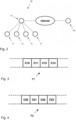
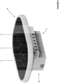
Figure 1 is a block diagram of the circuit part of a two-way wireless device adapted to be used as a node for a control network that is designed to control at least one electric load, for example an electric lamp; -
Figure 2 is a diagrammatic view of a point-to-point control network in which nodes consist of devices like that ofFigure 1 ; -
Figure 3 is a diagrammatic view of a data packet transmitted by the device ofFigure 1 ; -
Figure 4 shows a data packet received by the device ofFigure 1 ; -
Figure 5 shows the functional connections in a possible wireless network that uses three two-way wireless devices as slave nodes; -
Figure 8 is a schematic view of a table, contained in a master node of a wireless network, representing the condition ofFigure 5 . - Referring to the accompanying drawings,
numeral 1 generally designates a two-way wireless device. - Using a plurality n of two-way wireless devices 1 a
wireless network 10 with a proprietary transmission protocol may be designed, with a plurality n ofslave nodes gateway 11. - The master node or
gateway 11 of thenetwork 10 may be connected to an Internet network, through a home Wi-Fi network. - The operation of the
network 10 may be programmed via an application available for download from an Internet site and for installation on a mobile communication device, such as asmartphone 15, which communicates with themaster node 11. - In the
network 10 every communication between thenodes smartphone 15 passes through the master orgateway node 11. - The
wireless network 10 may be, for example, a point-to-multipoint wireless network (such as the one ofFigure 2 ) or a mesh network. - In the mesh configuration, in addition to their receive-and-transmit operation with the master node or
gateway 11, the n slave nodes of thenetwork 10 can also operate as repeaters with one another (if one of thenodes 1 is not able to directly communicate with themaster node 11. - The
wireless network 10 can be used, for example, to regulate at least oneelectric load 100, for example anelectric lamp 100. - In the described embodiment, the
device 1 comprises acontainer 8 whose shape and size allow it to fit into a conventional wall-recessed box (e.g. the box typically known as "503 box") or a conventional recessed junction box. - Therefore, the
container 8 comprises a first side, orfront side 81, intended to be exposed, and a second side, or rear side, 82, intended to remain inside the box 80. - In the illustrated example, the
device 1 comprises aprogrammable processor 2, a radio-frequency transmitter 51, a radio-frequency receiver 52, at least oneantenna actuator 3, for regulating the power absorbed by an electric load, and at least onesensor - For the purposes of the present description,
actuator 3 relates to a device that converts a control signal into an action. - The
actuator 3 is of the non-automatically operating type; it is actuated by a control signal from themicroprocessor 2. - Since it is a non-automatic actuator, it is not able to disconnect the line unless it receives a control signal from the
microprocessor 2. - The
term actuator 3 comprises solid-state relays, dimmers and any other electronic regulator adapted to regulate the power absorbed by an electric load through an external intervention. - For the purposes of the present description, the
term sensor - The
programmable processor 2 comprises aclock 21. - In the illustrated example, the
programmable processor 2 is a microcontroller whose operation is regulated by a management program (firmware) stored inside anon-volatile memory 22. - As more clearly explained below, the
programmable processor 2 is adapted to generate first data packets P1 and to process second data packets P2. - In the illustrated example, the
non-volatile memory 22 of theprogrammable processor 2 comprises aregister 221. - The
register 221 comprises afirst field 221a, which uniquely identifies thedevice 1, and at least onesecond field 221b which uniquely identifies theactuator 3 associated with the device 1 (or the actuators associated with thedevice 1 if there are multiple actuators). - The
microcontroller 2 used in thedevice 1 may be, for example, an ESP microchip 32 available from Esppressif. - In the illustrated example, the
actuator 3 is a solid-state switching device which comprises a conventional TRIAC 31 and a conventional trigger signal generatingcircuit 4, for controlling the gate of the TRIAC 31, which is in turn controlled by theprogrammable processor 2. - The
trigger 4 may be connected to themicrocontroller 2 via aconventional bus 20, for example aconventional SPI bus 20. - The signal generated by the
trigger 4 and addressed to the gate of the TRIAC 31 may be, for example, a square-wave signal, with a duty-cycle that can be adjusted according to users' needs. - The TRIAC 31 is electrically connected to two
electrical terminals 301, 302 (accessible from thesecond side 82 of the container 8) which are intended to receive the ends of two wires of a phase of a commercial power system. - The TRIAC 31 may be used as an on/off switch or as a dimmer.
- The radio-
frequency transmitter 51 is designed to send, to thenetwork 10, first data packets P1 (or output data packets from the device 1) generated by theprogrammable processor 2. - The radio-
frequency receiver 52 is designed to receive, from thenetwork 10, second data packets P2 (or input data packets) addressed to theprogrammable processor 2. - Therefore, the
programmable processor 2 is able to communicate with themaster node 11 of thenetwork 10, by sending it first data packets P1 and receiving from it second data packets P2. - The first and second data packets P1, P2 (described in greater detail below) respectively comprise a field C10 and C20 for managing
network synchronization 10. - The data packets P1 and P2 may also comprise a field, located at the beginning of the data packet, which contains data packet synchronization bits and a field containing an error correcting code.
- In the illustrated embodiment, the first data packets P1, or transmitted data packets, have a format other than the format of the second data packets P2, or received data packets.
- As mentioned above, at least one
antenna programmable processor 2. - In the illustrated example, two
distinct antennas - A
first antenna 521 is connected to thetransmitter 51, for data transmission, and asecond antenna 522 is connected to thereceiver 52, for data reception. - In an alternative embodiment, not shown, there may be a single antenna with a conventional switch device for alternately connecting the antenna with the
transmitter 51 and thereceiver 52. - In the illustrated embodiment, the
radio frequency transmitter 51 and theradio frequency receiver 52 are adapted to operate in the UHF band. - In a possible embodiment, the
transmitter 51 and thereceiver 52 may be integrated in the same microchip that contains themicrocontroller 2. - The
transmitter 51 may be a low power UHF transmitter (for example with an output power of up to 20 mWatt). - In a possible embodiment of the
network 10 themaster node 11 is designed using adevice 1 that differs from thedevices 1 used for theslave nodes - Each data packet P1 comprises a field C10 containing synchronization information for the
network 10 and a field C11 identifying the sender node 1I (and hence thedevice 1 that generated the packet). - Each data packet P1 comprises a field C12 identifying at least one
sensor - The data packets P2 that come from the
master node 11 and are addressed to themicrocontroller 2 of the device 1 (i.e. thenode 1j that is the ultimate recipient of the communication) comprise a field C20 containing synchronization information for thenetwork 10, a field C21 identifying thereceiver node 1j, and hence thedevice 1 that is the receiver of the data packet P2, a field C22 identifying theactuator 3 associated with the receiver node 1j (contained in thedevice 1 to which the data packet P2 is addressed) and a field C23 representative of a control signal for theactuator 3. - In the illustrated example, the field C23 of the data packet P2 contains an on/off control signal to be sent to the
trigger 4, which in turn controls theTRIAC 31. - The generation of the control signals to be sent to the
actuators 3 of thenetwork 10 may be also remotely controlled, for example by means of the aforementioned smartphone application, available for download from the Internet and for installation on thesmartphone 15. - The
sensor first side 81 of thecontainer 8 and is connected to themicrocontroller 2 via a conventional bus, for example a conventional SPI bus. - The
sensor more actuators 3, associated with one ormore slave nodes network 10, to regulate one or moreelectric loads 100. - The actuators of the
network 10 may be triggered not only by thesensor 6, but also remotely from thesmartphone 15. - The signal generated by the
sensor 6, 9 (which passes through the master node 11) may also be sent to thesmartphone 15 to provide an updated state of operation of thenetwork 10. - The
non-volatile memory 221 of theprogrammable processor 2 comprises at least onethird field 221c which uniquely identifies thesensor - In the illustrated example, the
sensor 6 is a control sensor operable by a finger. - As mentioned above, the
first sensor 6 may comprise atactile sensor 6, for example a capacitive tactile sensor. - This solution avoids the risk of failures associated with the wear of mechanical components and thus improves the reliability of the
device 1. - In an alternative embodiment (not shown), the
control sensor 6 may be a mechanically actuated button. - The
device 1 may comprise a conventional electroacoustic transducer (not shown) which beeps when thecontrol sensor 6 is actuated by the user. - The two-
way wireless device 1 may comprise a first light-emittingdevice 71 which is adapted to illuminate thefirst side 81 of thecontainer 8 and, in particular, the actuation area of thecontrol sensor 6. - The first light-emitting
device 71 facilitates the identification of the position of thecontrol sensor 6 and is particularly useful in the dark. - In a possible embodiment, the first light-emitting
device 71 comprises an LED. - In a possible embodiment, the two-
way wireless device 1 may comprise, in addition to or instead of thetouch sensor 6, amotion detection sensor 9. - The
motion detection sensor 9 may be, for example, a conventional passive infrared sensor. - The
motion detection sensor 9 may be used, for example, to control an actuator 3 (for example to turn on the lights) or to inform the user that manages the network 10 (for example through the smartphone 15) that there are people at home. - In the smartphone application that manages the
network 10, eachslave node 1 of thenetwork 10, eachactuator 3, eachsensor electric load 100 may be represented by icons. - The
device 1 further comprises a conventional DC power supply (not shown), which may receive power by the same commercial power system that supplies power to theloads 100 managed by thenetwork 10. - The
master node 11 of thenetwork 10 contains a table 12 (as shown inFigure 8 ) representing the association between eachactuator 3 of each node of thenetwork 10, and hence of eachdevice 1 of thenetwork 10, and eachsensor device 1 of thenetwork 10. - The values indicated in Table 12 are representative of the functional connections as shown in
Figure 5 . - For this purpose, the
devices 1, thesensors actuators 3 may be identified by unique identification codes. - The table 12 may be created and modified by the user remotely, for example through the aforementioned application available for download from the Internet and for installation on the
smartphone 15. - In the illustrated example, each record of the table 12 comprises a first field F1, a second field F2, a third field F3 and a fourth field F4.
- The contents of the first four fields F1, F2, F3 and F4 are defined by the user, for example via the
smartphone 15, and may be modified at a later time. - The first field F1 identifies a
sender node 1I of thenetwork 10, from which a first data packet P1 is sent. - The second field F2 identifies a
sensor sender node 1I which transmits the first data packet P1. - The third field F3 identifies a
node 1j which is the node with which the actuator to be triggered is associated, and hence the receiver node for the second data packet P2. - The fourth field F4 identifies an
actuator 3 associated with thereceiver node 1j for the data packet P2. - The association between the
actuators 3 and thesensors various nodes network 10 is created by the user as desired. - Therefore, one-to-one, one-to-many and many-to-one associations may be created between the
actuators 3 and thesensors network 10. - In other words, the state change of a
sensor 6 associated with anode 1 of thenetwork 10 can control one ormore actuator devices 3 associated with thevarious nodes network 10. - Likewise, each
actuator 3 associated with a node of thenetwork 10 can be triggered by one ormore sensors 6 associated with the nodes of the network 10 (as well as by the smartphone 15). It should be noted that even when anactuator 3 and asensor actuator 3 and thesensor 6 of thesame wireless device 1 is implied. - Every time that the
master node 11 receives a first data packet P1, a comparison is made between the fields C11 and C12 of the first data packet P1 with the first two fields F1, F2 of each record of the table 12 contained in thegateway 11. - For each matching record of the table 12 the contents of the following fields F3 and F4 are then checked.
- Then, the
gateway 11 creates a data packet P2 that comprises afield 20 containing synchronization information for thenetwork 10, a field C21 identifying thereceiver node 1j for the data packet P2, a field C22 identifying anactuator 3 associated with thenode 1j and a field C23 to be sent to theactuator 3 of thenode 1j corresponding to the content of the field C13 of the first data packet P1 or anyway having a value that is a function of the field C13. - The example of
Figure 5 shows the functional connections in a possible network for regulating electric loads which comprises three devices 1 (and hence three slave nodes) each comprising three sensors and three actuators. - In this example, the first actuator of the first node may be triggered indifferently, by the third button of the first node, the third button of the second node and the first button of the third node.
- Again, in this example, the first button of the first node may simultaneously control the third actuator of the second node and the first actuator of the third node.
- In the illustrated embodiment as long as the finger is held on a
control sensor 6, themicrocontroller 2 cyclically creates data packets P1 (or frames) which are temporarily stored in a volatile memory 23 of themicrocontroller 2. - As mentioned above, each data packet P1 comprises a field C10 containing synchronization information for the
network 10 and a field C11 identifying the sender node 1I (and hence thedevice 1 that transmitted the packet), a field C12 identifying thesensor - For example, in the case of a conventional
tactile sensor 6 designed to control solid-state relays, the state of the sensor can assume two values (on/off). - If the
tactile sensor 6 is designed to control a dimmer, then its state can assume a plurality of values between two extremes. - If the
actuator 3 is a dimmer, by varying the time during which the finger remains thetactile sensor 6, the user can also modulate the electric power supplied to theelectric load 100. - Then, the content of the volatile memory 23 is transmitted, directly or through other nodes, to the
master node 11. - In the illustrated embodiment of the
network 10, the data packets P1 transmitted by then slave nodes master node 11 have a format that differs from the format of the data packets P2 transmitted from themaster node 11 to then slave nodes - In one embodiment, not shown, the
device 1 may also comprise a device (not shown) capable of generating email messages or messages to a cloud with a PCP protocol. - This solution may be particularly interesting because it can create a
network 10 that can be also used as a remotely controlled alarm system. - In a possible embodiment, the
device 1 may comprise a second light-emittingdevice 72. - The second light-emitting
device 72 may perform various functions, for example it can be used to give the user potentially interesting information of potential interest such as, for example, the mode of operation of the two-way wireless device 1 or of thenetwork 10. - Such communications may take place, for example, by generating luminous variations of considerable magnitude and speed and/or by changing the color temperature.
- The second light-emitting
device 72 can also be used, more simply, to create plays of light or pleasing light effects. - In the illustrated example, the second light-emitting
device 72 comprises a plurality of LEDs adapted to generate, for example, diffused light. - In a possible embodiment, each
device 1 comprises three distinct control sensors 6 (namely three distinct touch-sensitive buttons) and threedistinct switching devices 3. -
- 1:
- Two-way wireless device
- 11, 12 ..1n
- Network nodes
- 10:
- Wireless Network
- 12:
- Table
- 15:
- Smartphone
- 2:
- Microcontroller
- 11:
- Master node or gateway
- 21:
- Clock
- 22:
- Nonvolatile memory
- 221:
- Register
- 23:
- Volatile Memory
- 3:
- Actuator
- 31:
- TRIAC
- 301.302
- Electrical terminals
- 4:
- Trigger
- 6:
- Tactile sensor (touch-sensitive button)
- 51:
- Transmitter
- 52:
- Receiver
- 511:
- Transmitting antenna
- 521:
- Receiving antenna
- 71:
- First light-emitting device
- 72:
- Second light-emitting device
- 8:
- Container
- 81:
- First side of the container
- 82:
- Second side of the container
- 9:
- Motion Sensor
- 100:
- Electric load
Claims (8)
- A two-way wireless device (1), usable as a slave node for a wireless network,
comprisinga) a programmable processor (2) comprising a clock (21) adapted to generate first data packets (P1) and to process second data packets (P2);b) a radio-frequency transmitter (51) for sending said first data packets (P1) generated by said programmable processor (2);c) a radio-frequency receiver (52) for receiving said second data packets (P2) addressed to said programmable processor (2),d) an antenna (521) connected to said transmitter (51) and an antenna (522) connected to said receiver (52);e) at least one non-automatically operating actuator, for regulating an electric load (100) according to a control signal from said programmable processor (2);f) at least one first sensor (6, 9) adapted to send a signal representative of its state to said programmable processor (2);g) a container (8) comprising a first side (81) and a second side (82); characterized in thath) said programmable processor (2) comprising a register (221) which comprises a first field (221a) identifying said device (1), a second field (221b) identifying said at least one actuator (3) and a third field (221c) identifying said at least one sensor (6, 9);
and in thati) said first sensor (6, 9) comprises a tactile sensor (6); and in thatj) said first sensor (6, 9) is placed on a side (81) of said container (8). - A device as claimed in claim 1, wherein
said first data packets (P1) comprise a field (C11) identifying said device (1), a field (C12) identifying said at least one sensor (6, 9) and a field (C13) identifying the state of said at least one sensor (6, 9). - A device as claimed in claim 2, wherein
said second data packets (P2) comprise a field (C21) identifying a receiving wireless device (1j) for said data packet (P2), a field (C22) identifying an actuator (3) associated with said receiving wireless device (1j), and a field (C23) representative of a control signal for an actuator (3) associated with said receiving wireless device (1j). - A device as claimed in any of the preceding claims, further comprising a first light-emitting device (71), for illuminating the actuation area of said first sensor (6).
- A device as claimed in any of the preceding claims, wherein said at least one sensor (6, 9) comprises a motion detection sensor (9).
- A device as claimed in any one of the previous claims, comprising a second light-emitting device (72) for indicating, in particular, the mode of operation of said two-way wireless device (1) and/or of a network (10) of which said device (1) is a part.
- A wireless network for controlling at least one electric load (100), wherein at least some of the nodes are devices as claimed in claim 1 or a claim dependent on claim 1.
- A method of controlling at least one electric load (100) via a wireless network (10) comprising n nodes (1, 1, 2, ... 1n) and a gateway (11), which includes the preliminary step of creating, in said gateway (11), a table (12), with each record of said table (12) comprising a first field (F1) identifying a sender node (1I), a second field (F2) identifying a sensor (6, 9) associated with said sender node (1I), said first sensor (6, 9) comprising a tactile sensor (6), a third field (F3) identifying a receiver node (1j) and a fourth field (F4) identifying an actuator (3), associated with said receiver node (1j), for regulating an electric load (100) and characterized by comprising the steps of:- creating a data packet (P1) which comprises a field (C10) containing synchronization information for said network (10), a field (C11) identifying a sender node (1I) of said network (10), a field (C12) identifying a sensor (6, 9) associated with said sender node (1I) and a third field (C13) representative of the state assumed by said sensor (6, 9);- transmitting said data packet (P1) to said gateway (11);- comparing said first and second fields (C11, C12) of said data packet (P1) with the first two fields (F1, F2) of each record of said table (12) contained in said gateway (11),- for each matching record of said table (12), checking the contents of the fields (F3) and (F4);- creating a data packet (P2) which comprises a field (20) containing synchronization information for the network (10), a field (C21) identifying the receiver node (1j) for the data packet (P2), a field (C22) identifying an actuator (3) associated with said node (1j) and a field (C23) representative of a control signal to be sent to the actuator (3) of the node (1j).
Applications Claiming Priority (1)
| Application Number | Priority Date | Filing Date | Title |
|---|---|---|---|
| IT102020000009544A IT202000009544A1 (en) | 2020-04-30 | 2020-04-30 | BIDIRECTIONAL WIRELESS DEVICE USABLE AS A NODE FOR A WIRELESS NETWORK TO REGULATE AT LEAST ONE ELECTRIC LOAD |
Publications (3)
| Publication Number | Publication Date |
|---|---|
| EP3905482A1 EP3905482A1 (en) | 2021-11-03 |
| EP3905482C0 EP3905482C0 (en) | 2025-04-02 |
| EP3905482B1 true EP3905482B1 (en) | 2025-04-02 |
Family
ID=71575678
Family Applications (1)
| Application Number | Title | Priority Date | Filing Date |
|---|---|---|---|
| EP21171567.7A Active EP3905482B1 (en) | 2020-04-30 | 2021-04-30 | Bidirectional wireless device |
Country Status (2)
| Country | Link |
|---|---|
| EP (1) | EP3905482B1 (en) |
| IT (1) | IT202000009544A1 (en) |
Family Cites Families (3)
| Publication number | Priority date | Publication date | Assignee | Title |
|---|---|---|---|---|
| US20080005558A1 (en) * | 2006-06-29 | 2008-01-03 | Battelle Memorial Institute | Methods and apparatuses for authentication and validation of computer-processable communications |
| JP5259069B2 (en) * | 2006-10-02 | 2013-08-07 | 株式会社東芝 | Circuit breaker switching control system |
| CA2927854C (en) * | 2013-10-23 | 2023-03-28 | Powercast Corporation | Automated system for lighting control |
-
2020
- 2020-04-30 IT IT102020000009544A patent/IT202000009544A1/en unknown
-
2021
- 2021-04-30 EP EP21171567.7A patent/EP3905482B1/en active Active
Also Published As
| Publication number | Publication date |
|---|---|
| EP3905482C0 (en) | 2025-04-02 |
| EP3905482A1 (en) | 2021-11-03 |
| IT202000009544A1 (en) | 2021-10-30 |
Similar Documents
| Publication | Publication Date | Title |
|---|---|---|
| CN1679376B (en) | Master-slave-based bidirectional radio frequency wireless lighting control system | |
| US20060097890A1 (en) | AC powered wireless control 3-way light switch transmitter | |
| US10936523B2 (en) | Communication module and lighting bus system having a network interface | |
| CN108449117A (en) | A kind of Internet of things system and method for network entry based on PLC | |
| CN106133800B (en) | Display device comprising a wireless interface and an interface to a bus system of a network control system | |
| EP3076763B1 (en) | Configuring a network connected lighting system | |
| WO2007069241A2 (en) | Active ip control device | |
| EP2132961B1 (en) | Control circuit, system for operating a device and device for programming such a control circuit | |
| KR102013291B1 (en) | Method for register/set TV information on the remote control device | |
| US20050258976A1 (en) | Household digital automation control system | |
| EP3905482A1 (en) | Bidirectional wireless device | |
| KR20180122199A (en) | LIGHT DEVICE FOR RELAYING THINGS, IoT SYSTEM INCLUDING THE SAME | |
| WO1999009780A1 (en) | Remote control system | |
| CN101025616B (en) | Wireless system with multi-device control | |
| US10986392B2 (en) | Hybrid IR/RF remote control system | |
| WO2017021799A1 (en) | Alternative means for actuation of electric loads connected to conventional switches | |
| KR101414864B1 (en) | Digital multiplex control system baesd wireless LAN | |
| JP6502563B1 (en) | Load control system | |
| GB2365231A (en) | Method and apparatus for the control of lighting circuits | |
| CN202261954U (en) | Multi-protocol power switch control system | |
| KR101608590B1 (en) | Apparatus and method for controlling a light device | |
| CN117595895B (en) | Multichannel radio frequency remote control system | |
| KR20190012248A (en) | LIGHT DEVICE FOR RELAYING THINGS, IoT SYSTEM INCLUDING THE SAME | |
| KR100742348B1 (en) | Home networking system with user-oriented shortcut mode | |
| CN106549861A (en) | A kind of multifunctional intellectual gateway |
Legal Events
| Date | Code | Title | Description |
|---|---|---|---|
| PUAI | Public reference made under article 153(3) epc to a published international application that has entered the european phase |
Free format text: ORIGINAL CODE: 0009012 |
|
| STAA | Information on the status of an ep patent application or granted ep patent |
Free format text: STATUS: THE APPLICATION HAS BEEN PUBLISHED |
|
| AK | Designated contracting states |
Kind code of ref document: A1 Designated state(s): AL AT BE BG CH CY CZ DE DK EE ES FI FR GB GR HR HU IE IS IT LI LT LU LV MC MK MT NL NO PL PT RO RS SE SI SK SM TR |
|
| B565 | Issuance of search results under rule 164(2) epc |
Effective date: 20210728 |
|
| STAA | Information on the status of an ep patent application or granted ep patent |
Free format text: STATUS: REQUEST FOR EXAMINATION WAS MADE |
|
| 17P | Request for examination filed |
Effective date: 20220414 |
|
| RBV | Designated contracting states (corrected) |
Designated state(s): AL AT BE BG CH CY CZ DE DK EE ES FI FR GB GR HR HU IE IS IT LI LT LU LV MC MK MT NL NO PL PT RO RS SE SI SK SM TR |
|
| STAA | Information on the status of an ep patent application or granted ep patent |
Free format text: STATUS: EXAMINATION IS IN PROGRESS |
|
| 17Q | First examination report despatched |
Effective date: 20220908 |
|
| GRAP | Despatch of communication of intention to grant a patent |
Free format text: ORIGINAL CODE: EPIDOSNIGR1 |
|
| STAA | Information on the status of an ep patent application or granted ep patent |
Free format text: STATUS: GRANT OF PATENT IS INTENDED |
|
| GRAS | Grant fee paid |
Free format text: ORIGINAL CODE: EPIDOSNIGR3 |
|
| GRAA | (expected) grant |
Free format text: ORIGINAL CODE: 0009210 |
|
| STAA | Information on the status of an ep patent application or granted ep patent |
Free format text: STATUS: THE PATENT HAS BEEN GRANTED |
|
| INTG | Intention to grant announced |
Effective date: 20250130 |
|
| AK | Designated contracting states |
Kind code of ref document: B1 Designated state(s): AL AT BE BG CH CY CZ DE DK EE ES FI FR GB GR HR HU IE IS IT LI LT LU LV MC MK MT NL NO PL PT RO RS SE SI SK SM TR |
|
| REG | Reference to a national code |
Ref country code: GB Ref legal event code: FG4D |
|
| REG | Reference to a national code |
Ref country code: CH Ref legal event code: EP |
|
| REG | Reference to a national code |
Ref country code: IE Ref legal event code: FG4D |
|
| REG | Reference to a national code |
Ref country code: DE Ref legal event code: R096 Ref document number: 602021028385 Country of ref document: DE |
|
| RAP4 | Party data changed (patent owner data changed or rights of a patent transferred) |
Owner name: WIDESIGN S.R.L. |
|
| U01 | Request for unitary effect filed |
Effective date: 20250407 |
|
| U07 | Unitary effect registered |
Designated state(s): AT BE BG DE DK EE FI FR IT LT LU LV MT NL PT RO SE SI Effective date: 20250415 |
|
| U20 | Renewal fee for the european patent with unitary effect paid |
Year of fee payment: 5 Effective date: 20250414 |
|
| PG25 | Lapsed in a contracting state [announced via postgrant information from national office to epo] |
Ref country code: ES Free format text: LAPSE BECAUSE OF FAILURE TO SUBMIT A TRANSLATION OF THE DESCRIPTION OR TO PAY THE FEE WITHIN THE PRESCRIBED TIME-LIMIT Effective date: 20250402 |
|
| PG25 | Lapsed in a contracting state [announced via postgrant information from national office to epo] |
Ref country code: NO Free format text: LAPSE BECAUSE OF FAILURE TO SUBMIT A TRANSLATION OF THE DESCRIPTION OR TO PAY THE FEE WITHIN THE PRESCRIBED TIME-LIMIT Effective date: 20250702 Ref country code: GR Free format text: LAPSE BECAUSE OF FAILURE TO SUBMIT A TRANSLATION OF THE DESCRIPTION OR TO PAY THE FEE WITHIN THE PRESCRIBED TIME-LIMIT Effective date: 20250703 |
|
| PG25 | Lapsed in a contracting state [announced via postgrant information from national office to epo] |
Ref country code: PL Free format text: LAPSE BECAUSE OF FAILURE TO SUBMIT A TRANSLATION OF THE DESCRIPTION OR TO PAY THE FEE WITHIN THE PRESCRIBED TIME-LIMIT Effective date: 20250402 |
|
| PG25 | Lapsed in a contracting state [announced via postgrant information from national office to epo] |
Ref country code: HR Free format text: LAPSE BECAUSE OF FAILURE TO SUBMIT A TRANSLATION OF THE DESCRIPTION OR TO PAY THE FEE WITHIN THE PRESCRIBED TIME-LIMIT Effective date: 20250402 |
|
| PG25 | Lapsed in a contracting state [announced via postgrant information from national office to epo] |
Ref country code: RS Free format text: LAPSE BECAUSE OF FAILURE TO SUBMIT A TRANSLATION OF THE DESCRIPTION OR TO PAY THE FEE WITHIN THE PRESCRIBED TIME-LIMIT Effective date: 20250702 |
|
| PG25 | Lapsed in a contracting state [announced via postgrant information from national office to epo] |
Ref country code: IS Free format text: LAPSE BECAUSE OF FAILURE TO SUBMIT A TRANSLATION OF THE DESCRIPTION OR TO PAY THE FEE WITHIN THE PRESCRIBED TIME-LIMIT Effective date: 20250802 |
|
| REG | Reference to a national code |
Ref country code: CH Ref legal event code: H13 Free format text: ST27 STATUS EVENT CODE: U-0-0-H10-H13 (AS PROVIDED BY THE NATIONAL OFFICE) Effective date: 20251125 |
|
| PG25 | Lapsed in a contracting state [announced via postgrant information from national office to epo] |
Ref country code: SM Free format text: LAPSE BECAUSE OF FAILURE TO SUBMIT A TRANSLATION OF THE DESCRIPTION OR TO PAY THE FEE WITHIN THE PRESCRIBED TIME-LIMIT Effective date: 20250402 |
|
| PG25 | Lapsed in a contracting state [announced via postgrant information from national office to epo] |
Ref country code: CH Free format text: LAPSE BECAUSE OF NON-PAYMENT OF DUE FEES Effective date: 20250430 |
|
| PG25 | Lapsed in a contracting state [announced via postgrant information from national office to epo] |
Ref country code: CZ Free format text: LAPSE BECAUSE OF FAILURE TO SUBMIT A TRANSLATION OF THE DESCRIPTION OR TO PAY THE FEE WITHIN THE PRESCRIBED TIME-LIMIT Effective date: 20250402 |
|
| PG25 | Lapsed in a contracting state [announced via postgrant information from national office to epo] |
Ref country code: SK Free format text: LAPSE BECAUSE OF FAILURE TO SUBMIT A TRANSLATION OF THE DESCRIPTION OR TO PAY THE FEE WITHIN THE PRESCRIBED TIME-LIMIT Effective date: 20250402 |
|
| PG25 | Lapsed in a contracting state [announced via postgrant information from national office to epo] |
Ref country code: MC Free format text: LAPSE BECAUSE OF FAILURE TO SUBMIT A TRANSLATION OF THE DESCRIPTION OR TO PAY THE FEE WITHIN THE PRESCRIBED TIME-LIMIT Effective date: 20250402 |
|
| PLBE | No opposition filed within time limit |
Free format text: ORIGINAL CODE: 0009261 |
|
| STAA | Information on the status of an ep patent application or granted ep patent |
Free format text: STATUS: NO OPPOSITION FILED WITHIN TIME LIMIT |
|
| REG | Reference to a national code |
Ref country code: CH Ref legal event code: L10 Free format text: ST27 STATUS EVENT CODE: U-0-0-L10-L00 (AS PROVIDED BY THE NATIONAL OFFICE) Effective date: 20260211 |
|
| 26N | No opposition filed |
Effective date: 20260105 |
|
| GBPC | Gb: european patent ceased through non-payment of renewal fee |
Effective date: 20250702 |
|
| PG25 | Lapsed in a contracting state [announced via postgrant information from national office to epo] |
Ref country code: GB Free format text: LAPSE BECAUSE OF NON-PAYMENT OF DUE FEES Effective date: 20250702 |
|
| PG25 | Lapsed in a contracting state [announced via postgrant information from national office to epo] |
Ref country code: IE Free format text: LAPSE BECAUSE OF NON-PAYMENT OF DUE FEES Effective date: 20250430 |
|
| U20 | Renewal fee for the european patent with unitary effect paid |
Year of fee payment: 6 Effective date: 20260312 |