EP3905478A1 - Power management circuit - Google Patents
Power management circuit Download PDFInfo
- Publication number
- EP3905478A1 EP3905478A1 EP21169950.9A EP21169950A EP3905478A1 EP 3905478 A1 EP3905478 A1 EP 3905478A1 EP 21169950 A EP21169950 A EP 21169950A EP 3905478 A1 EP3905478 A1 EP 3905478A1
- Authority
- EP
- European Patent Office
- Prior art keywords
- circuit
- power level
- attributes
- ultrasonic signal
- power
- Prior art date
- Legal status (The legal status is an assumption and is not a legal conclusion. Google has not performed a legal analysis and makes no representation as to the accuracy of the status listed.)
- Withdrawn
Links
Images


Classifications
-
- H—ELECTRICITY
- H02—GENERATION; CONVERSION OR DISTRIBUTION OF ELECTRIC POWER
- H02J—ELECTRIC POWER NETWORKS; CIRCUIT ARRANGEMENTS OR SYSTEMS FOR SUPPLYING OR DISTRIBUTING ELECTRIC POWER; SYSTEMS FOR STORING ELECTRIC ENERGY
- H02J7/00—Circuit arrangements for charging or discharging batteries or for supplying loads from batteries
- H02J7/02—Circuit arrangements for charging or discharging batteries or for supplying loads from batteries for charging batteries from AC mains by converters
- H02J7/04—Regulation of charging current or voltage
-
- H—ELECTRICITY
- H02—GENERATION; CONVERSION OR DISTRIBUTION OF ELECTRIC POWER
- H02J—ELECTRIC POWER NETWORKS; CIRCUIT ARRANGEMENTS OR SYSTEMS FOR SUPPLYING OR DISTRIBUTING ELECTRIC POWER; SYSTEMS FOR STORING ELECTRIC ENERGY
- H02J7/00—Circuit arrangements for charging or discharging batteries or for supplying loads from batteries
- H02J7/90—Regulation of charging or discharging current or voltage
- H02J7/971—Regulation of charging or discharging current or voltage the charge cycle being controlled or terminated in response to non-electric parameters
-
- B—PERFORMING OPERATIONS; TRANSPORTING
- B60—VEHICLES IN GENERAL
- B60L—PROPULSION OF ELECTRICALLY-PROPELLED VEHICLES; SUPPLYING ELECTRIC POWER FOR AUXILIARY EQUIPMENT OF ELECTRICALLY-PROPELLED VEHICLES; ELECTRODYNAMIC BRAKE SYSTEMS FOR VEHICLES IN GENERAL; MAGNETIC SUSPENSION OR LEVITATION FOR VEHICLES; MONITORING OPERATING VARIABLES OF ELECTRICALLY-PROPELLED VEHICLES; ELECTRIC SAFETY DEVICES FOR ELECTRICALLY-PROPELLED VEHICLES
- B60L53/00—Methods of charging batteries, specially adapted for electric vehicles; Charging stations or on-board charging equipment therefor; Exchange of energy storage elements in electric vehicles
- B60L53/10—Methods of charging batteries, specially adapted for electric vehicles; Charging stations or on-board charging equipment therefor; Exchange of energy storage elements in electric vehicles characterised by the energy transfer between the charging station and the vehicle
- B60L53/14—Conductive energy transfer
- B60L53/16—Connectors, e.g. plugs or sockets, specially adapted for charging electric vehicles
-
- B—PERFORMING OPERATIONS; TRANSPORTING
- B60—VEHICLES IN GENERAL
- B60L—PROPULSION OF ELECTRICALLY-PROPELLED VEHICLES; SUPPLYING ELECTRIC POWER FOR AUXILIARY EQUIPMENT OF ELECTRICALLY-PROPELLED VEHICLES; ELECTRODYNAMIC BRAKE SYSTEMS FOR VEHICLES IN GENERAL; MAGNETIC SUSPENSION OR LEVITATION FOR VEHICLES; MONITORING OPERATING VARIABLES OF ELECTRICALLY-PROPELLED VEHICLES; ELECTRIC SAFETY DEVICES FOR ELECTRICALLY-PROPELLED VEHICLES
- B60L53/00—Methods of charging batteries, specially adapted for electric vehicles; Charging stations or on-board charging equipment therefor; Exchange of energy storage elements in electric vehicles
- B60L53/60—Monitoring or controlling charging stations
- B60L53/62—Monitoring or controlling charging stations in response to charging parameters, e.g. current, voltage or electrical charge
-
- B—PERFORMING OPERATIONS; TRANSPORTING
- B60—VEHICLES IN GENERAL
- B60L—PROPULSION OF ELECTRICALLY-PROPELLED VEHICLES; SUPPLYING ELECTRIC POWER FOR AUXILIARY EQUIPMENT OF ELECTRICALLY-PROPELLED VEHICLES; ELECTRODYNAMIC BRAKE SYSTEMS FOR VEHICLES IN GENERAL; MAGNETIC SUSPENSION OR LEVITATION FOR VEHICLES; MONITORING OPERATING VARIABLES OF ELECTRICALLY-PROPELLED VEHICLES; ELECTRIC SAFETY DEVICES FOR ELECTRICALLY-PROPELLED VEHICLES
- B60L53/00—Methods of charging batteries, specially adapted for electric vehicles; Charging stations or on-board charging equipment therefor; Exchange of energy storage elements in electric vehicles
- B60L53/60—Monitoring or controlling charging stations
- B60L53/66—Data transfer between charging stations and vehicles
- B60L53/665—Methods related to measuring, billing or payment
-
- H—ELECTRICITY
- H02—GENERATION; CONVERSION OR DISTRIBUTION OF ELECTRIC POWER
- H02J—ELECTRIC POWER NETWORKS; CIRCUIT ARRANGEMENTS OR SYSTEMS FOR SUPPLYING OR DISTRIBUTING ELECTRIC POWER; SYSTEMS FOR STORING ELECTRIC ENERGY
- H02J7/00—Circuit arrangements for charging or discharging batteries or for supplying loads from batteries
- H02J7/40—Circuit arrangements for charging or discharging batteries or for supplying loads from batteries characterised by the exchange of charge or discharge related data
- H02J7/42—Circuit arrangements for charging or discharging batteries or for supplying loads from batteries characterised by the exchange of charge or discharge related data with electronic devices having internal batteries, e.g. mobile phones
-
- H—ELECTRICITY
- H02—GENERATION; CONVERSION OR DISTRIBUTION OF ELECTRIC POWER
- H02J—ELECTRIC POWER NETWORKS; CIRCUIT ARRANGEMENTS OR SYSTEMS FOR SUPPLYING OR DISTRIBUTING ELECTRIC POWER; SYSTEMS FOR STORING ELECTRIC ENERGY
- H02J7/00—Circuit arrangements for charging or discharging batteries or for supplying loads from batteries
- H02J7/60—Circuit arrangements for charging or discharging batteries or for supplying loads from batteries including safety or protection arrangements
-
- Y—GENERAL TAGGING OF NEW TECHNOLOGICAL DEVELOPMENTS; GENERAL TAGGING OF CROSS-SECTIONAL TECHNOLOGIES SPANNING OVER SEVERAL SECTIONS OF THE IPC; TECHNICAL SUBJECTS COVERED BY FORMER USPC CROSS-REFERENCE ART COLLECTIONS [XRACs] AND DIGESTS
- Y02—TECHNOLOGIES OR APPLICATIONS FOR MITIGATION OR ADAPTATION AGAINST CLIMATE CHANGE
- Y02T—CLIMATE CHANGE MITIGATION TECHNOLOGIES RELATED TO TRANSPORTATION
- Y02T10/00—Road transport of goods or passengers
- Y02T10/60—Other road transportation technologies with climate change mitigation effect
- Y02T10/70—Energy storage systems for electromobility, e.g. batteries
-
- Y—GENERAL TAGGING OF NEW TECHNOLOGICAL DEVELOPMENTS; GENERAL TAGGING OF CROSS-SECTIONAL TECHNOLOGIES SPANNING OVER SEVERAL SECTIONS OF THE IPC; TECHNICAL SUBJECTS COVERED BY FORMER USPC CROSS-REFERENCE ART COLLECTIONS [XRACs] AND DIGESTS
- Y02—TECHNOLOGIES OR APPLICATIONS FOR MITIGATION OR ADAPTATION AGAINST CLIMATE CHANGE
- Y02T—CLIMATE CHANGE MITIGATION TECHNOLOGIES RELATED TO TRANSPORTATION
- Y02T10/00—Road transport of goods or passengers
- Y02T10/60—Other road transportation technologies with climate change mitigation effect
- Y02T10/7072—Electromobility specific charging systems or methods for batteries, ultracapacitors, supercapacitors or double-layer capacitors
-
- Y—GENERAL TAGGING OF NEW TECHNOLOGICAL DEVELOPMENTS; GENERAL TAGGING OF CROSS-SECTIONAL TECHNOLOGIES SPANNING OVER SEVERAL SECTIONS OF THE IPC; TECHNICAL SUBJECTS COVERED BY FORMER USPC CROSS-REFERENCE ART COLLECTIONS [XRACs] AND DIGESTS
- Y02—TECHNOLOGIES OR APPLICATIONS FOR MITIGATION OR ADAPTATION AGAINST CLIMATE CHANGE
- Y02T—CLIMATE CHANGE MITIGATION TECHNOLOGIES RELATED TO TRANSPORTATION
- Y02T90/00—Enabling technologies or technologies with a potential or indirect contribution to GHG emissions mitigation
- Y02T90/10—Technologies relating to charging of electric vehicles
- Y02T90/12—Electric charging stations
-
- Y—GENERAL TAGGING OF NEW TECHNOLOGICAL DEVELOPMENTS; GENERAL TAGGING OF CROSS-SECTIONAL TECHNOLOGIES SPANNING OVER SEVERAL SECTIONS OF THE IPC; TECHNICAL SUBJECTS COVERED BY FORMER USPC CROSS-REFERENCE ART COLLECTIONS [XRACs] AND DIGESTS
- Y02—TECHNOLOGIES OR APPLICATIONS FOR MITIGATION OR ADAPTATION AGAINST CLIMATE CHANGE
- Y02T—CLIMATE CHANGE MITIGATION TECHNOLOGIES RELATED TO TRANSPORTATION
- Y02T90/00—Enabling technologies or technologies with a potential or indirect contribution to GHG emissions mitigation
- Y02T90/10—Technologies relating to charging of electric vehicles
- Y02T90/14—Plug-in electric vehicles
-
- Y—GENERAL TAGGING OF NEW TECHNOLOGICAL DEVELOPMENTS; GENERAL TAGGING OF CROSS-SECTIONAL TECHNOLOGIES SPANNING OVER SEVERAL SECTIONS OF THE IPC; TECHNICAL SUBJECTS COVERED BY FORMER USPC CROSS-REFERENCE ART COLLECTIONS [XRACs] AND DIGESTS
- Y02—TECHNOLOGIES OR APPLICATIONS FOR MITIGATION OR ADAPTATION AGAINST CLIMATE CHANGE
- Y02T—CLIMATE CHANGE MITIGATION TECHNOLOGIES RELATED TO TRANSPORTATION
- Y02T90/00—Enabling technologies or technologies with a potential or indirect contribution to GHG emissions mitigation
- Y02T90/10—Technologies relating to charging of electric vehicles
- Y02T90/16—Information or communication technologies improving the operation of electric vehicles
Definitions
- the present specification relates to systems, methods, apparatuses, devices, articles of manufacture and instructions for power management.
- a power management circuit comprising: an ultrasonic transmitter configured to generate an ultrasonic signal having a set of transmitted ultrasonic signal attributes; an ultrasonic receiver configured to detect the ultrasonic signal having a set of received ultrasonic signal attributes; wherein the power management circuit is configured to cause a device to be operated at a first power level and a second power level; and a proximity detection circuit configured to transition the device from the first power level to the second power level in response to a preselected difference between the transmitted set of ultrasonic signal attributes and the received set of ultrasonic signal attributes.
- the first power level is higher than the second power level.
- the first and second power levels are non-zero.
- the first power level includes a first current level for charging the device; and the second power level includes a second current level, less than the first current level, for charging the device.
- the first power level includes a first voltage level for charging the device; and the second power level includes a second voltage level, less than the first current level, for charging the device.
- the transmitted and received attributes include at least one of: an amplitude, a phase, an impedance, a delay, and an ultrasonic signal power level.
- the transmitted and received attributes are configured to vary based on at least one of: a proximity or movement of a user's hand, skin or clothing to the device, a proximity or movement of an object, such as another device, a desk surface, a smartphone, or a battery charger, next to the device, and a proximity or movement of a user's hand to a cable connected to the device.
- the proximity detection circuit is configured to transition the device from the first power level to the second power level in response to a preselected variation in the difference between the transmitted set of attributes and the received set of attributes over a preselected time period.
- the proximity detection circuit is configured to not transition the device from the first power level to the second power level if the preselected variation in the difference between the transmitted set of attributes and the received set of attributes does not vary over the preselected time period.
- the proximity detection circuit is configured to transition the device from the first power level to the second power level in response to either or both the preselected difference between the transmitted set of attributes and the received set of attributes, or movement of the device.
- the power management circuit is embedded in at least one of: a battery charger, a mobile charger, a battery powered device, an electric car, or an electric car charger.
- a power source wherein the power source is at least one of: a main AC source, or another battery; and wherein the proximity detection circuit is configured to transition the power source from the first power level to the second power level in response to the preselected difference between the transmitted set of attributes and the received set of attributes.
- the ultrasonic transmitter is configured to pulse the ultrasonic signal; a frequency of the ultrasonic signal is set based on a predefined rate at which the preselected difference between the transmitted set of attributes and the received set of attributes changes; and a frequency of the ultrasonic signal is set based on a predefined rate at which a user can disrupt charging of the device.
- the connector is configured to be coupled to a cable from a power source; and the proximity detection circuit is configured to transition the device from the first power level to the second power level in response to an object near the cable.
- the device is a smartphone; and the object is a user's hand.
- the device is an electric car charger; and the object is an electric car or a user's hand.
- the cable has a first end connector configured to withstand a first arcing current; the cable has a second end connector configured to withstand a second arcing current; wherein the proximity detection circuit is configured to transition the device from the first power level to the second power level in response to the object near the first end connector; the proximity detection circuit is configured to transition the device from the first power level to a third power level in response to the object near the second end connector; and the second power is greater than the third power level.
- the ultrasonic transmitter is a speaker; and the ultrasonic receiver is a microphone.
- the device is configured to be coupled to a wireless charger; the ultrasonic transmitter and ultrasonic receiver are configured to be coupled to the wireless charger; and the wireless charger is within a detection range of the ultrasonic signal.
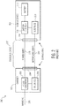
- Figure 1 is a first example 100 of charging between a first device 102 and a second device 104.
- the first device 102 is a charger and the second device 104 is a mobile device.
- the first device 102 includes an AC/DC converter 106 and a first connector 108.
- the second device 104 includes a battery charger 110, a battery 112, and a second connector 114.
- the first device 102 is connected to a mains AC 115 (e.g. an AC wall outlet power source) and a first end of a charging cable 116.
- the second device 104 is coupled to a second end of the charging cable 116.
- power at a fixed voltage and maximum current level is then transferred from the first device 102 to the second device 104.
- Figure 2 is a second example 200 of charging between a first device 202 and a second device 204.
- the first device 202 is a charger and the second device 204 is a mobile device.
- the first device 202 includes an AC/DC converter 206, a first connector 208, and a first interface circuit 218.
- the second device 204 includes a battery charger 210, a battery 212, a second connector 214, and a second interface circuit 220.
- the first device 202 is connected to a mains AC 215 (e.g. an AC wall outlet power source) and a first end of a charging cable 217.
- the second device 204 is coupled to a second end of the charging cable 217.
- the charging cable 217 includes a set of power wires 216 and a set of interface wires 222.
- the first device 202 is a smart charger and the additional communication interface circuits 218, 220 and wires 222 communicate the second device's 204 charging parameters (e.g. acceptable voltage and current levels) and the first device's 202 charging parameters (e.g. ability of the smart charger to provide voltage and current to the second device 204).
- Such interface communications enable boost charging and/or fast charging in some example embodiments.
- Smart chargers thus can exchange device type information through the interface connection 218, 220, 222.
- Certain types of second devices 204 have certain voltage, current and power parameters, and the smart charger adjusts its output to fall within those parameters.
- Some smart chargers also ask the second device 204 for its battery's current charge state.
- ultrasound-based circuits and algorithms for predicting when a device receiving power is about to be disconnected from a power source e.g. a user's behavior is about to result in disconnection of the device
- reduce or stop power transfer in anticipation of such disconnect.
- the ultrasound-based circuits and algorithms apply to devices of any size, from smartphones to electric cars.
- the power transfer can be wired (e.g. wire/cable) or wireless (e.g. inductive).
- Predicted disconnections can be intentional or accidental (e.g. an electric car driving away from a charge point with the power cable still connected to the car).
- Example embodiments incorporating multiple ultrasound-based circuits can also distinguish between users and device-types, having one power disconnect profile for a first user and/or device that is different from a power disconnect profile from a second user and/or device.
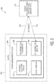
- Figure 3 is a first example 300 of a power management circuit 304 in a device 302.
- the power management circuit 304 includes an ultrasonic transmitter 306, an ultrasonic receiver 308, and a proximity detection circuit 310.
- the power management circuit 304 presents an example embodiment of a circuit for permitting faster charging using higher currents without damaging the device 302.
- the power management circuit 304 is configured to charge the device 302 at a first power level and a second power level.
- the ultrasonic transmitter 306 is configured to generate a transmitted ultrasonic signal 316 having a set of transmitted ultrasonic signal attributes.
- the ultrasonic receiver 308 is configured to detect a received ultrasonic signal 318 from a reflected version of the transmitted ultrasonic signal 316 which interacts with an object 314.
- the ultrasonic signal attributes include at least: amplitude, phase, impedance, and ultrasonic signal power level.
- the object 314 is herein defined broadly to include at least: a user's hand, another device, a desk surface, a smartphone, a battery charger, a docking station, a car charger, a user's skin, or a user's clothes.
- the ultrasonic transmitter 306 and ultrasonic receiver 308 in some example embodiments can be configured to interface with existing audio (e.g. speakers and microphones), DSP and MCU hardware on the device 302 (e.g. a smart phone).
- the ultrasound frequency being used can be limited to about 20 kHz, since sample rates of a smartphone's audio DAC-ADC can be as low as 44 kHz, meaning that sound up to 22 kHz can be resolved.
- the ultrasound frequency however should be high enough in order to be inaudible to smartphone user's ear. This means the frequency should be higher than 18 kHz. Thus a frequency band between 18.5 kHz and 20 kHz would be compatible to an existing smartphone operating system like Android OS.
- the received ultrasonic signal 318 has a set of received ultrasonic signal attributes.
- the proximity detection circuit 310 is configured to transition the device 302 from the first power level (e.g. for charging) to the second power level (e.g. for charging) in response to a preselected difference between the transmitted ultrasonic signal 316 attributes and the received ultrasonic signal 318 attributes.
- the proximity detection circuit 310 includes a software algorithm or circuits configured to detect small motions up to a few meters from the device 302 using Doppler shift techniques.
- ultrasonic motion sensing in some example embodiments may not be very directional, such that individual connectors could be monitored, a number false-positives (i.e. where the proximity detection circuit 310 concludes that device is about to be disconnected while it is not), and a number of false-negatives (i.e. situation where the proximity detection circuit 310 failed to detect that device is about to be disconnected) can be within an acceptable error range.
- Example embodiments of the power management circuit 304 may or may not be configured to be connected to a physical charging cable.
- the power management circuit 304 may put the device 302 (e.g. a charger, a smartphone, electric car, etc.) in a lower or higher power state for a variety of reasons (e.g. for high power wireless charging).
- the preselected difference between the transmitted ultrasonic signal 316 attributes and the received ultrasonic signal 318 attributes is a range (e.g. phase difference between 90 degrees and 270 degrees).
- the preselected difference between the transmitted ultrasonic signal 316 attributes and the received ultrasonic signal 318 attributes is a variation (i.e. non-steady state) from a baseline (i.e. steady-state) ultrasonic signal attribute. Note in various example embodiments, the proximity of an object can be detected even if only one of the attributes of the sets 316, 318 differ.
- the power management circuit 304 shifts the device 302 to a lower charging current level, or switches the device 302 completely off before disconnect by a user putting the device 302 in a state where an arc or voltage surge could occur (e.g. pulling out a charging cable, see Figures 4 and 5 , connected to a device such as a mobile device, a smartphone, tablet, or a laptop).
- the transmitted ultrasonic signal 316 in some example embodiments can be pulsed for low power operation.
- the transmitted ultrasonic signal's 316 repetition frequency depends on the required reaction time for the device 302 to be switched between high and low power modes. For example, a user about to pick up the device 302 or disconnect a charging cable may need a faster response than if the proximity detection circuit 310 is used to wake-up the device 302.
- an accelerometer 312 i.e. gyro detector
- gyro detector can be added to detect movement of the device 302 (e.g. intentional movement by a user or some other force such as falling off a table), thereby causing the power management circuit 304 to command a reduction in a charging or other current.
- proximity detection and movement detection work in combination for certain high to low power mode shifts, and in other example shift the device 302 from high to low (or low to high) power mode individually.
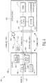
- Figure 4 is an example 400 of a power management circuit distributed between a first device 402 and a second device 404.
- the first device 402 is a charger and the second device 404 is a mobile device.
- the first device 402 includes an AC/DC converter 406, a first connector 408, a first interface circuit 418, an ultrasonic transmitter 424, and an ultrasonic receiver 426. Functionality for the proximity detection circuit is distributed between the first interface circuit 418, the ultrasonic transmitter 424 and the ultrasonic receiver 426.
- the second device 404 includes a battery charger 410, a battery 412, a second connector 414, a second interface circuit 420 and an accelerometer 428 (e.g. gyro detector).
- a battery charger 410 a battery 412
- a second connector 414 a second interface circuit 420
- an accelerometer 428 e.g. gyro detector
- the first device 402 is connected to a mains AC 415 (e.g. an AC wall outlet power source) and a first end of a charging cable.
- the second device 404 is coupled to a second end of the charging cable.
- the charging cable includes a set of power wires 416 and a set of interface wires 422. The power wires 416 between the charger 402 and mobile device 404 conduct current to charge the battery 412 of the mobile device 404.
- the ultrasonic transmitter 424 generates and transmits an ultrasonic signal 430 and the ultrasonic receiver 426 receives ultrasonic signal 432 for proximity detection of an object 434 (e.g. a hand in this example).
- the transmitted ultrasonic signal 430 and received ultrasonic signal 432 shown enable the proximity detection circuit in the device 402 to detect any changes due to the proximity of the hand 434 to one or both of the connectors 408, 414.
- the proximity detection circuit detects if the mobile device 404 is in a steady state, and thus can be charged by the charger 402 at a high power level. However, once the hand 434 comes within a predefined distance from the charging cable, the proximity detection circuit reduces the charging power level to a lower power level to prevent damage to the cable or connectors 408, 414 upon any disconnect.
- the mobile device 404 will send a message to the charger 402 via the interface wires 422 requesting that the charging current be reduced.
- the proximity detection circuit is distributed between both the charger 402 and the mobile device 404.
- Figure 5 is a second example 500 of charging between a first device 502 and a second device 504 using a power management circuit.
- the first device 502 is a charger and the second device 504 is a mobile device.
- the first device 502 includes an AC/DC converter 506, a first connector 508, and a first interface circuit 518.
- the second device 504 includes a battery charger 510, a battery 512, a second connector 514, a second interface circuit 520, an ultrasonic transmitter 524, an ultrasonic receiver 526, and an accelerometer 528 (e.g. gyro detector). Functionality for the proximity detection circuit is distributed between the second interface circuit 520, the ultrasonic transmitter 524, the ultrasonic receiver 526, and the accelerometer 528.
- the first device 502 is connected to a mains AC 515 (e.g. an AC wall outlet power source) and a first end of a charging cable.
- the second device 504 is coupled to a second end of the charging cable.
- the charging cable includes a set of power wires 516 and a set of interface wires 522. The power wires 516 between the charger 502 and mobile device 504 conduct current to charge the battery 512 of the mobile device 504.
- the ultrasonic transmitter 524 generates and transmits an ultrasonic signal 530 and the ultrasonic receiver 526 receives ultrasonic signal 532 for proximity detection of an object 534 (e.g. a hand in this example).
- the transmitted ultrasonic signal 530 and received ultrasonic signal 532 shown enable the proximity detection circuit in the device 502 to detect any changes due to the proximity of the hand 534 to one or both of the connectors 508, 514.
- these instructions/steps are implemented as functional and software instructions.
- the instructions can be implemented either using logic gates, application specific chips, firmware, as well as other hardware forms.
- the instructions are embodied as a set of executable instructions in a non-transitory computer-readable or computer-usable media which are effected on a computer or machine programmed with and controlled by said executable instructions.
- Said instructions are loaded for execution on a processor (such as one or more CPUs).
- Said processor includes microprocessors, microcontrollers, processor modules or subsystems (including one or more microprocessors or microcontrollers), or other control or computing devices.
- a processor can refer to a single component or to plural components.
- Said computer-readable or computer-usable storage medium or media is (are) considered to be part of an article (or article of manufacture).
- An article or article of manufacture can refer to any manufactured single component or multiple components.
- the non-transitory machine or computer-usable media or mediums as defined herein excludes signals, but such media or mediums may be capable of receiving and processing information from signals and/or other transitory mediums.
Landscapes
- Engineering & Computer Science (AREA)
- Power Engineering (AREA)
- Transportation (AREA)
- Mechanical Engineering (AREA)
- Charge And Discharge Circuits For Batteries Or The Like (AREA)
- Telephone Function (AREA)
Abstract
One example discloses a power management circuit (400), including: an ultrasonic transmitter (424) configured to generate an ultrasonic signal (430) having a set of transmitted ultrasonic signal attributes; an ultrasonic receiver (426) configured to detect the ultrasonic signal (432) having a set of received ultrasonic signal attributes; wherein the power management circuit (400) is configured to cause a device (402, 404) to be operated at a first power level and a second power level; and a proximity detection circuit (distributed between both 402, 404) configured to transition the device (402, 404) from the first power level to the second power level in response to a preselected difference between the transmitted set of ultrasonic signal attributes and the received set of ultrasonic signal attributes.
Description
- The present specification relates to systems, methods, apparatuses, devices, articles of manufacture and instructions for power management.
- According to an example embodiment, a power management circuit, comprising: an ultrasonic transmitter configured to generate an ultrasonic signal having a set of transmitted ultrasonic signal attributes; an ultrasonic receiver configured to detect the ultrasonic signal having a set of received ultrasonic signal attributes; wherein the power management circuit is configured to cause a device to be operated at a first power level and a second power level; and a proximity detection circuit configured to transition the device from the first power level to the second power level in response to a preselected difference between the transmitted set of ultrasonic signal attributes and the received set of ultrasonic signal attributes.
- In another example embodiment, the first power level is higher than the second power level.
- In another example embodiment, the first and second power levels are non-zero.
- In another example embodiment, the first power level includes a first current level for charging the device; and the second power level includes a second current level, less than the first current level, for charging the device.
- In another example embodiment, the first power level includes a first voltage level for charging the device; and the second power level includes a second voltage level, less than the first current level, for charging the device.
- In another example embodiment, the transmitted and received attributes include at least one of: an amplitude, a phase, an impedance, a delay, and an ultrasonic signal power level.
- In another example embodiment, the transmitted and received attributes are configured to vary based on at least one of: a proximity or movement of a user's hand, skin or clothing to the device, a proximity or movement of an object, such as another device, a desk surface, a smartphone, or a battery charger, next to the device, and a proximity or movement of a user's hand to a cable connected to the device.
- In another example embodiment, the proximity detection circuit is configured to transition the device from the first power level to the second power level in response to a preselected variation in the difference between the transmitted set of attributes and the received set of attributes over a preselected time period.
- In another example embodiment, the proximity detection circuit is configured to not transition the device from the first power level to the second power level if the preselected variation in the difference between the transmitted set of attributes and the received set of attributes does not vary over the preselected time period.
- In another example embodiment, further comprising an accelerometer configured to detect movement of the device.
- In another example embodiment, the proximity detection circuit is configured to transition the device from the first power level to the second power level in response to either or both the preselected difference between the transmitted set of attributes and the received set of attributes, or movement of the device.
- In another example embodiment, the power management circuit is embedded in at least one of: a battery charger, a mobile charger, a battery powered device, an electric car, or an electric car charger.
- In another example embodiment, further comprising a power source; wherein the power source is at least one of: a main AC source, or another battery; and wherein the proximity detection circuit is configured to transition the power source from the first power level to the second power level in response to the preselected difference between the transmitted set of attributes and the received set of attributes.
- In another example embodiment, the ultrasonic transmitter is configured to pulse the ultrasonic signal; a frequency of the ultrasonic signal is set based on a predefined rate at which the preselected difference between the transmitted set of attributes and the received set of attributes changes; and a frequency of the ultrasonic signal is set based on a predefined rate at which a user can disrupt charging of the device.
- In another example embodiment, further comprising a connector coupled to an external surface of the device; wherein the ultrasonic transmitter and ultrasonic receiver are coupled to the connector; and wherein the connector is within a detection range of the ultrasonic signal.
- In another example embodiment, the connector is configured to be coupled to a cable from a power source; and the proximity detection circuit is configured to transition the device from the first power level to the second power level in response to an object near the cable.
- In another example embodiment, the device is a smartphone; and the object is a user's hand.
- In another example embodiment, the device is an electric car charger; and the object is an electric car or a user's hand.
- In another example embodiment, the cable has a first end connector configured to withstand a first arcing current; the cable has a second end connector configured to withstand a second arcing current; wherein the proximity detection circuit is configured to transition the device from the first power level to the second power level in response to the object near the first end connector; the proximity detection circuit is configured to transition the device from the first power level to a third power level in response to the object near the second end connector; and the second power is greater than the third power level.
- In another example embodiment, the ultrasonic transmitter is a speaker; and the ultrasonic receiver is a microphone.
- In another example embodiment, the device is configured to be coupled to a wireless charger; the ultrasonic transmitter and ultrasonic receiver are configured to be coupled to the wireless charger; and the wireless charger is within a detection range of the ultrasonic signal.
- The above discussion is not intended to represent every example embodiment or every implementation within the scope of the current or future Claim sets. The Figures and Detailed Description that follow also exemplify various example embodiments.
- Various example embodiments may be more completely understood in consideration of the following Detailed Description in connection with the accompanying Drawings.
-
-
Figure 1 is a first example of charging between a first device and a second device. -
Figure 2 is a second example of charging between a first device and a second device. -
Figure 3 is a first example of a power management circuit in a device; -
Figure 4 is an example of a power management circuit distributed between a first device and a second device. -
Figure 5 is a second example of charging between a first device and a second device using a power management circuit. - While the disclosure is amenable to various modifications and alternative forms, specifics thereof have been shown by way of example in the drawings and will be described in detail. It should be understood, however, that other embodiments, beyond the particular embodiments described, are possible as well. All modifications, equivalents, and alternative embodiments falling within the spirit and scope of the appended claims are covered as well.
-
Figure 1 (Prior Art) is a first example 100 of charging between afirst device 102 and asecond device 104. In this example thefirst device 102 is a charger and thesecond device 104 is a mobile device. - The
first device 102 includes an AC/DC converter 106 and afirst connector 108. Thesecond device 104 includes abattery charger 110, abattery 112, and asecond connector 114. - The
first device 102 is connected to a mains AC 115 (e.g. an AC wall outlet power source) and a first end of acharging cable 116. Thesecond device 104 is coupled to a second end of thecharging cable 116. During charging, power at a fixed voltage and maximum current level is then transferred from thefirst device 102 to thesecond device 104. -
Figure 2 (Prior Art) is a second example 200 of charging between afirst device 202 and asecond device 204. In this example thefirst device 202 is a charger and thesecond device 204 is a mobile device. - The
first device 202 includes an AC/DC converter 206, afirst connector 208, and afirst interface circuit 218. Thesecond device 204 includes abattery charger 210, abattery 212, asecond connector 214, and asecond interface circuit 220. - The
first device 202 is connected to a mains AC 215 (e.g. an AC wall outlet power source) and a first end of acharging cable 217. Thesecond device 204 is coupled to a second end of thecharging cable 217. Thecharging cable 217 includes a set ofpower wires 216 and a set ofinterface wires 222. - In this example 200, the
first device 202 is a smart charger and the additionalcommunication interface circuits wires 222 communicate the second device's 204 charging parameters (e.g. acceptable voltage and current levels) and the first device's 202 charging parameters (e.g. ability of the smart charger to provide voltage and current to the second device 204). Such interface communications enable boost charging and/or fast charging in some example embodiments. - Smart chargers thus can exchange device type information through the
interface connection second devices 204 have certain voltage, current and power parameters, and the smart charger adjusts its output to fall within those parameters. Some smart chargers also ask thesecond device 204 for its battery's current charge state. - An ability to charge mobile devices, such as mobile phones, faster however is beneficial. Faster charging, in some example embodiments, requires higher charging currents. When applying such high charging currents, a sudden disconnect by a user (e.g. by pulling out a charging cable connector plug) may result in damage to the connector and/or the electronic circuits because of arcing. This is a spark occurring on the terminals of the connectors induced by a sudden discontinuity of the charging current.
- Now discussed are example ultrasound-based circuits and algorithms for predicting when a device receiving power is about to be disconnected from a power source (e.g. a user's behavior is about to result in disconnection of the device) and reduce or stop power transfer in anticipation of such disconnect.
- The ultrasound-based circuits and algorithms apply to devices of any size, from smartphones to electric cars. Also the power transfer can be wired (e.g. wire/cable) or wireless (e.g. inductive). Predicted disconnections can be intentional or accidental (e.g. an electric car driving away from a charge point with the power cable still connected to the car).
- In various example embodiments incorporating multiple ultrasound-based circuits, a distinction can be made between which-end of a wired coupling is being disconnected (e.g. a less arcing sensitive Type-A connector at a laptop end, or a more arcing sensitive micro-USB connector at a smartphone end).
- Example embodiments incorporating multiple ultrasound-based circuits, can also distinguish between users and device-types, having one power disconnect profile for a first user and/or device that is different from a power disconnect profile from a second user and/or device.
-
Figure 3 is a first example 300 of apower management circuit 304 in adevice 302. Thepower management circuit 304 includes anultrasonic transmitter 306, anultrasonic receiver 308, and aproximity detection circuit 310. Thepower management circuit 304 presents an example embodiment of a circuit for permitting faster charging using higher currents without damaging thedevice 302. - The
power management circuit 304 is configured to charge thedevice 302 at a first power level and a second power level. Theultrasonic transmitter 306 is configured to generate a transmittedultrasonic signal 316 having a set of transmitted ultrasonic signal attributes. Theultrasonic receiver 308 is configured to detect a receivedultrasonic signal 318 from a reflected version of the transmittedultrasonic signal 316 which interacts with anobject 314. - The ultrasonic signal attributes include at least: amplitude, phase, impedance, and ultrasonic signal power level. The
object 314 is herein defined broadly to include at least: a user's hand, another device, a desk surface, a smartphone, a battery charger, a docking station, a car charger, a user's skin, or a user's clothes. - The
ultrasonic transmitter 306 andultrasonic receiver 308 in some example embodiments can be configured to interface with existing audio (e.g. speakers and microphones), DSP and MCU hardware on the device 302 (e.g. a smart phone). In such embodiments, the ultrasound frequency being used can be limited to about 20 kHz, since sample rates of a smartphone's audio DAC-ADC can be as low as 44 kHz, meaning that sound up to 22 kHz can be resolved. The ultrasound frequency however should be high enough in order to be inaudible to smartphone user's ear. This means the frequency should be higher than 18 kHz. Thus a frequency band between 18.5 kHz and 20 kHz would be compatible to an existing smartphone operating system like Android OS. - The received
ultrasonic signal 318 has a set of received ultrasonic signal attributes. Theproximity detection circuit 310 is configured to transition thedevice 302 from the first power level (e.g. for charging) to the second power level (e.g. for charging) in response to a preselected difference between the transmittedultrasonic signal 316 attributes and the receivedultrasonic signal 318 attributes. - In some example embodiments, the
proximity detection circuit 310 includes a software algorithm or circuits configured to detect small motions up to a few meters from thedevice 302 using Doppler shift techniques. - In some example embodiments, a few meters ultrasonic range is sufficient to cover a distance between the
device 302 and the object 314 (e.g. both ends of a charging cable). While ultrasonic motion sensing in some example embodiments may not be very directional, such that individual connectors could be monitored, a number false-positives (i.e. where theproximity detection circuit 310 concludes that device is about to be disconnected while it is not), and a number of false-negatives (i.e. situation where theproximity detection circuit 310 failed to detect that device is about to be disconnected) can be within an acceptable error range. - Example embodiments of the
power management circuit 304 may or may not be configured to be connected to a physical charging cable. Thepower management circuit 304 may put the device 302 (e.g. a charger, a smartphone, electric car, etc.) in a lower or higher power state for a variety of reasons (e.g. for high power wireless charging). - In one example embodiment the preselected difference between the transmitted
ultrasonic signal 316 attributes and the receivedultrasonic signal 318 attributes is a range (e.g. phase difference between 90 degrees and 270 degrees). In another example embodiment the preselected difference between the transmittedultrasonic signal 316 attributes and the receivedultrasonic signal 318 attributes is a variation (i.e. non-steady state) from a baseline (i.e. steady-state) ultrasonic signal attribute. Note in various example embodiments, the proximity of an object can be detected even if only one of the attributes of thesets - Thus as an example, to avoid voltage spikes and arcing, the
power management circuit 304 shifts thedevice 302 to a lower charging current level, or switches thedevice 302 completely off before disconnect by a user putting thedevice 302 in a state where an arc or voltage surge could occur (e.g. pulling out a charging cable, seeFigures 4 and5 , connected to a device such as a mobile device, a smartphone, tablet, or a laptop). - The transmitted
ultrasonic signal 316 in some example embodiments can be pulsed for low power operation. The transmitted ultrasonic signal's 316 repetition frequency depends on the required reaction time for thedevice 302 to be switched between high and low power modes. For example, a user about to pick up thedevice 302 or disconnect a charging cable may need a faster response than if theproximity detection circuit 310 is used to wake-up thedevice 302. - Additionally an accelerometer 312 (i.e. gyro detector) can be added to detect movement of the device 302 (e.g. intentional movement by a user or some other force such as falling off a table), thereby causing the
power management circuit 304 to command a reduction in a charging or other current. - In some example embodiments, proximity detection and movement detection work in combination for certain high to low power mode shifts, and in other example shift the
device 302 from high to low (or low to high) power mode individually. -
Figure 4 is an example 400 of a power management circuit distributed between afirst device 402 and asecond device 404. In this example thefirst device 402 is a charger and thesecond device 404 is a mobile device. - The
first device 402 includes an AC/DC converter 406, afirst connector 408, afirst interface circuit 418, anultrasonic transmitter 424, and anultrasonic receiver 426. Functionality for the proximity detection circuit is distributed between thefirst interface circuit 418, theultrasonic transmitter 424 and theultrasonic receiver 426. - The
second device 404 includes abattery charger 410, abattery 412, asecond connector 414, asecond interface circuit 420 and an accelerometer 428 (e.g. gyro detector). - The
first device 402 is connected to a mains AC 415 (e.g. an AC wall outlet power source) and a first end of a charging cable. Thesecond device 404 is coupled to a second end of the charging cable. The charging cable includes a set ofpower wires 416 and a set ofinterface wires 422. Thepower wires 416 between thecharger 402 andmobile device 404 conduct current to charge thebattery 412 of themobile device 404. - The
ultrasonic transmitter 424 generates and transmits anultrasonic signal 430 and theultrasonic receiver 426 receivesultrasonic signal 432 for proximity detection of an object 434 (e.g. a hand in this example). The transmittedultrasonic signal 430 and receivedultrasonic signal 432 shown enable the proximity detection circuit in thedevice 402 to detect any changes due to the proximity of thehand 434 to one or both of theconnectors - The proximity detection circuit detects if the
mobile device 404 is in a steady state, and thus can be charged by thecharger 402 at a high power level. However, once thehand 434 comes within a predefined distance from the charging cable, the proximity detection circuit reduces the charging power level to a lower power level to prevent damage to the cable orconnectors - In some examples, especially in combination with the
accelerometer 428 in themobile device 404, themobile device 404 will send a message to thecharger 402 via theinterface wires 422 requesting that the charging current be reduced. In this example, the proximity detection circuit is distributed between both thecharger 402 and themobile device 404. -
Figure 5 is a second example 500 of charging between afirst device 502 and asecond device 504 using a power management circuit. In this example thefirst device 502 is a charger and thesecond device 504 is a mobile device. - The
first device 502 includes an AC/DC converter 506, afirst connector 508, and afirst interface circuit 518. - The
second device 504 includes abattery charger 510, abattery 512, asecond connector 514, asecond interface circuit 520, anultrasonic transmitter 524, anultrasonic receiver 526, and an accelerometer 528 (e.g. gyro detector). Functionality for the proximity detection circuit is distributed between thesecond interface circuit 520, theultrasonic transmitter 524, theultrasonic receiver 526, and theaccelerometer 528. - The
first device 502 is connected to a mains AC 515 (e.g. an AC wall outlet power source) and a first end of a charging cable. Thesecond device 504 is coupled to a second end of the charging cable. The charging cable includes a set ofpower wires 516 and a set ofinterface wires 522. Thepower wires 516 between thecharger 502 andmobile device 504 conduct current to charge thebattery 512 of themobile device 504. - The
ultrasonic transmitter 524 generates and transmits anultrasonic signal 530 and theultrasonic receiver 526 receivesultrasonic signal 532 for proximity detection of an object 534 (e.g. a hand in this example). The transmittedultrasonic signal 530 and receivedultrasonic signal 532 shown enable the proximity detection circuit in thedevice 502 to detect any changes due to the proximity of thehand 534 to one or both of theconnectors - Various instructions and/or operational steps discussed in the above Figures can be executed in any order, unless a specific order is explicitly stated. Also, those skilled in the art will recognize that while some example sets of instructions/steps have been discussed, the material in this specification can be combined in a variety of ways to yield other examples as well, and are to be understood within a context provided by this detailed description.
- In some example embodiments these instructions/steps are implemented as functional and software instructions. In other embodiments, the instructions can be implemented either using logic gates, application specific chips, firmware, as well as other hardware forms.
- When the instructions are embodied as a set of executable instructions in a non-transitory computer-readable or computer-usable media which are effected on a computer or machine programmed with and controlled by said executable instructions. Said instructions are loaded for execution on a processor (such as one or more CPUs). Said processor includes microprocessors, microcontrollers, processor modules or subsystems (including one or more microprocessors or microcontrollers), or other control or computing devices. A processor can refer to a single component or to plural components. Said computer-readable or computer-usable storage medium or media is (are) considered to be part of an article (or article of manufacture). An article or article of manufacture can refer to any manufactured single component or multiple components. The non-transitory machine or computer-usable media or mediums as defined herein excludes signals, but such media or mediums may be capable of receiving and processing information from signals and/or other transitory mediums.
- It will be readily understood that the components of the embodiments as generally described herein and illustrated in the appended figures could be arranged and designed in a wide variety of different configurations. Thus, the detailed description of various embodiments, as represented in the figures, is not intended to limit the scope of the present disclosure, but is merely representative of various embodiments. While the various aspects of the embodiments are presented in drawings, the drawings are not necessarily drawn to scale unless specifically indicated.
- The present invention may be embodied in other specific forms without departing from its spirit or essential characteristics. The described embodiments are to be considered in all respects only as illustrative and not restrictive. The scope of the invention is, therefore, indicated by the appended claims rather than by this detailed description. All changes which come within the meaning and range of equivalency of the claims are to be embraced within their scope.
- Reference throughout this specification to features, advantages, or similar language does not imply that all of the features and advantages that may be realized with the present invention should be or are in any single embodiment of the invention. Rather, language referring to the features and advantages is understood to mean that a specific feature, advantage, or characteristic described in connection with an embodiment is included in at least one embodiment of the present invention. Thus, discussions of the features and advantages, and similar language, throughout this specification may, but do not necessarily, refer to the same embodiment.
- Furthermore, the described features, advantages, and characteristics of the invention may be combined in any suitable manner in one or more embodiments. One skilled in the relevant art will recognize, in light of the description herein, that the invention can be practiced without one or more of the specific features or advantages of a particular embodiment. In other instances, additional features and advantages may be recognized in certain embodiments that may not be present in all embodiments of the invention.
- Reference throughout this specification to "one embodiment," "an embodiment," or similar language means that a particular feature, structure, or characteristic described in connection with the indicated embodiment is included in at least one embodiment of the present invention. Thus, the phrases "in one embodiment," "in an embodiment," and similar language throughout this specification may, but do not necessarily, all refer to the same embodiment.
Claims (15)
- A power management circuit, comprising:an ultrasonic transmitter configured to generate an ultrasonic signal having a set of transmitted ultrasonic signal attributes;an ultrasonic receiver configured to detect the ultrasonic signal having a set of received ultrasonic signal attributes;wherein the power management circuit is configured to cause a device to be operated at a first power level and a second power level; anda proximity detection circuit configured to transition the device from the first power level to the second power level in response to a preselected difference between the transmitted set of ultrasonic signal attributes and the received set of ultrasonic signal attributes.
- The circuit of claim 1:
wherein the first power level is higher than the second power level. - The circuit of claim 1 or 2:
wherein the first and second power levels are non-zero. - The circuit of any preceding claim, wherein:the first power level includes a one of a first current level and a first voltage level for charging the device; andthe second power level includes a second respective voltage or current level, less than the first respective voltage or current level, for charging the device.
- The circuit of any preceding claim:
wherein the transmitted and received attributes include at least one of: an amplitude, a phase, an impedance, a delay, and an ultrasonic signal power level. - The circuit of any preceding claim:
wherein the transmitted and received attributes are configured to vary based on at least one of: a proximity or movement of a user's hand, skin or clothing to the device, a proximity or movement of an object, such as another device, a desk surface, a smartphone, or a battery charger, next to the device, and a proximity or movement of a user's hand to a cable connected to the device. - The circuit of any preceding claim:
wherein the proximity detection circuit is configured to transition the device from the first power level to the second power level in response to a preselected variation in the difference between the transmitted set of attributes and the received set of attributes over a preselected time period. - The circuit of any preceding claim:
further comprising an accelerometer configured to detect movement of the device. - The circuit of claim 8:
wherein the proximity detection circuit is configured to transition the device from the first power level to the second power level in response to either or both the preselected difference between the transmitted set of attributes and the received set of attributes, or movement of the device. - The circuit of any preceding claim:
wherein the power management circuit is embedded in at least one of: a battery charger, a mobile charger, a battery powered device, an electric car, or an electric car charger. - The circuit of any of claims 1 to 10:further comprising a power source;wherein the power source is at least one of: a main AC source, or another battery; andwherein the proximity detection circuit is configured to transition the power source from the first power level to the second power level in response to the preselected difference between the transmitted set of attributes and the received set of attributes.
- The circuit of any preceding claim:wherein the ultrasonic transmitter is configured to pulse the ultrasonic signal;wherein a frequency of the ultrasonic signal is set based on a predefined rate at which the preselected difference between the transmitted set of attributes and the received set of attributes changes; andwherein a frequency of the ultrasonic signal is set based on a predefined rate at which a user can disrupt charging of the device.
- The circuit of any preceding claim:further comprising a connector coupled to an external surface of the device;wherein the ultrasonic transmitter and ultrasonic receiver are coupled to the connector; andwherein the connector is within a detection range of the ultrasonic signal.
- The circuit of claim 13:wherein the connector is configured to be coupled to a cable from a power source; andwherein the proximity detection circuit is configured to transition the device from the first power level to the second power level in response to an object near the cable.
- The circuit of claim 14:
wherein a one of the device is a smartphone and the object is a user's hand, and the device is an electric car charger and the object is an electric car or a user's hand.
Applications Claiming Priority (1)
| Application Number | Priority Date | Filing Date | Title |
|---|---|---|---|
| US16/860,944 US11368036B2 (en) | 2020-04-28 | 2020-04-28 | Power management circuit |
Publications (1)
| Publication Number | Publication Date |
|---|---|
| EP3905478A1 true EP3905478A1 (en) | 2021-11-03 |
Family
ID=75659789
Family Applications (1)
| Application Number | Title | Priority Date | Filing Date |
|---|---|---|---|
| EP21169950.9A Withdrawn EP3905478A1 (en) | 2020-04-28 | 2021-04-22 | Power management circuit |
Country Status (3)
| Country | Link |
|---|---|
| US (1) | US11368036B2 (en) |
| EP (1) | EP3905478A1 (en) |
| CN (1) | CN113572247A (en) |
Families Citing this family (1)
| Publication number | Priority date | Publication date | Assignee | Title |
|---|---|---|---|---|
| CN116224818B (en) * | 2023-05-10 | 2023-09-08 | 深圳市创诺新电子科技有限公司 | Control method and control device of household power system and household power system |
Citations (3)
| Publication number | Priority date | Publication date | Assignee | Title |
|---|---|---|---|---|
| DE102014206164A1 (en) * | 2014-04-01 | 2015-10-01 | Volkswagen Aktiengesellschaft | Infrastructure-side plug for a charging cable for charging an electrically driven means of transportation |
| DE102017203504A1 (en) * | 2017-03-03 | 2018-09-06 | Volkswagen Aktiengesellschaft | A method for unlocking a charging plug in connection with a charging operation of an electrically driven vehicle |
| EP3386064A1 (en) * | 2017-04-03 | 2018-10-10 | Nxp B.V. | Power management circuit |
Family Cites Families (14)
| Publication number | Priority date | Publication date | Assignee | Title |
|---|---|---|---|---|
| US5956626A (en) | 1996-06-03 | 1999-09-21 | Motorola, Inc. | Wireless communication device having an electromagnetic wave proximity sensor |
| US8169196B2 (en) | 2007-06-27 | 2012-05-01 | Sony Mobile Communications Ab | Charging device |
| US9722671B2 (en) * | 2011-05-27 | 2017-08-01 | uBeam Inc. | Oscillator circuits for wireless power transfer |
| KR101868041B1 (en) * | 2012-04-16 | 2018-06-18 | 한국전자통신연구원 | Ultrasonic wireless communication apparatus and method for wireless power transmission |
| US20180048178A1 (en) * | 2013-06-25 | 2018-02-15 | Energous Corporation | System and methods of using electromagnetic waves to wirelessly deliver power to electronic devices |
| US10992185B2 (en) * | 2012-07-06 | 2021-04-27 | Energous Corporation | Systems and methods of using electromagnetic waves to wirelessly deliver power to game controllers |
| US9906275B2 (en) * | 2015-09-15 | 2018-02-27 | Energous Corporation | Identifying receivers in a wireless charging transmission field |
| JP6863365B2 (en) * | 2016-03-22 | 2021-04-21 | 日本電気株式会社 | Monitoring device, monitoring system and monitoring method |
| US10923954B2 (en) * | 2016-11-03 | 2021-02-16 | Energous Corporation | Wireless power receiver with a synchronous rectifier |
| US10389161B2 (en) * | 2017-03-15 | 2019-08-20 | Energous Corporation | Surface mount dielectric antennas for wireless power transmitters |
| US10875406B2 (en) * | 2017-01-19 | 2020-12-29 | Solaredge Technologies Ltd. | Electric-vehicle charging apparatus |
| WO2018183892A1 (en) * | 2017-03-30 | 2018-10-04 | Energous Corporation | Flat antennas having two or more resonant frequencies for use in wireless power transmission systems |
| US10122219B1 (en) * | 2017-10-10 | 2018-11-06 | Energous Corporation | Systems, methods, and devices for using a battery as a antenna for receiving wirelessly delivered power from radio frequency power waves |
| US11342798B2 (en) * | 2017-10-30 | 2022-05-24 | Energous Corporation | Systems and methods for managing coexistence of wireless-power signals and data signals operating in a same frequency band |
-
2020
- 2020-04-28 US US16/860,944 patent/US11368036B2/en active Active
-
2021
- 2021-04-22 EP EP21169950.9A patent/EP3905478A1/en not_active Withdrawn
- 2021-04-28 CN CN202110468660.2A patent/CN113572247A/en active Pending
Patent Citations (3)
| Publication number | Priority date | Publication date | Assignee | Title |
|---|---|---|---|---|
| DE102014206164A1 (en) * | 2014-04-01 | 2015-10-01 | Volkswagen Aktiengesellschaft | Infrastructure-side plug for a charging cable for charging an electrically driven means of transportation |
| DE102017203504A1 (en) * | 2017-03-03 | 2018-09-06 | Volkswagen Aktiengesellschaft | A method for unlocking a charging plug in connection with a charging operation of an electrically driven vehicle |
| EP3386064A1 (en) * | 2017-04-03 | 2018-10-10 | Nxp B.V. | Power management circuit |
Also Published As
| Publication number | Publication date |
|---|---|
| CN113572247A (en) | 2021-10-29 |
| US20210336470A1 (en) | 2021-10-28 |
| US11368036B2 (en) | 2022-06-21 |
Similar Documents
| Publication | Publication Date | Title |
|---|---|---|
| EP3389248A2 (en) | Method and apparatus for easy switching between wired and wireless headset with convenient charging | |
| KR101683651B1 (en) | Noise reducing apparatus and method of the wireless charging device | |
| CN101727428B (en) | Apparatus and method for controlling USB switching circuit in portable terminal | |
| CN104810879B (en) | Fast charging method and system | |
| KR101933066B1 (en) | Charging method, mobile device, charging device and charging system | |
| CN104810909B (en) | Fast charging control method and system | |
| JP5669320B2 (en) | Electronics | |
| CN104113114B (en) | Mobile terminal different power self-adaptive charging method | |
| EP3142195B1 (en) | Earphone seat | |
| US20080054854A1 (en) | Charger | |
| CN103746434A (en) | Charging method and charging system | |
| US10025351B2 (en) | System for controlling peripherals connected to a docking station | |
| KR20140058331A (en) | Method and apparatus for wireless power transmission | |
| US20190089823A1 (en) | Information processing device | |
| CN103986211A (en) | Intelligent charging control method | |
| CN106655423A (en) | Wireless charging method and device | |
| EP3142382B1 (en) | Method, apparatus and system for supplying power to active noise cancelling earphone | |
| US11368036B2 (en) | Power management circuit | |
| CN108695952B (en) | Power Management Circuit | |
| CN111279574A (en) | Terminal device and charging control method | |
| CN109275058B (en) | Dual mode earphone system, bluetooth device and cable | |
| CN104105020A (en) | Bluetooth earphones, charging method and charging system | |
| CN102640393B (en) | Power Bridge Circuit for Bidirectional Inductive Signal Transmission | |
| CN105978069A (en) | Charging method and apparatus of mobile terminal, and mobile terminal | |
| CN107769332B (en) | Rechargeable equipment, charging method thereof and charging device |
Legal Events
| Date | Code | Title | Description |
|---|---|---|---|
| PUAI | Public reference made under article 153(3) epc to a published international application that has entered the european phase |
Free format text: ORIGINAL CODE: 0009012 |
|
| STAA | Information on the status of an ep patent application or granted ep patent |
Free format text: STATUS: THE APPLICATION HAS BEEN PUBLISHED |
|
| AK | Designated contracting states |
Kind code of ref document: A1 Designated state(s): AL AT BE BG CH CY CZ DE DK EE ES FI FR GB GR HR HU IE IS IT LI LT LU LV MC MK MT NL NO PL PT RO RS SE SI SK SM TR |
|
| B565 | Issuance of search results under rule 164(2) epc |
Effective date: 20210910 |
|
| STAA | Information on the status of an ep patent application or granted ep patent |
Free format text: STATUS: THE APPLICATION IS DEEMED TO BE WITHDRAWN |
|
| 18D | Application deemed to be withdrawn |
Effective date: 20220504 |