EP3905377A1 - Power battery pack and vehicle - Google Patents
Power battery pack and vehicle Download PDFInfo
- Publication number
- EP3905377A1 EP3905377A1 EP19904418.1A EP19904418A EP3905377A1 EP 3905377 A1 EP3905377 A1 EP 3905377A1 EP 19904418 A EP19904418 A EP 19904418A EP 3905377 A1 EP3905377 A1 EP 3905377A1
- Authority
- EP
- European Patent Office
- Prior art keywords
- base plate
- side beam
- partition plates
- air passage
- battery
- Prior art date
- Legal status (The legal status is an assumption and is not a legal conclusion. Google has not performed a legal analysis and makes no representation as to the accuracy of the status listed.)
- Pending
Links
- 238000004880 explosion Methods 0.000 claims abstract description 107
- 238000005192 partition Methods 0.000 claims description 199
- 239000000779 smoke Substances 0.000 claims description 82
- 238000004891 communication Methods 0.000 claims description 47
- 238000010586 diagram Methods 0.000 description 8
- 238000000034 method Methods 0.000 description 3
- RNFJDJUURJAICM-UHFFFAOYSA-N 2,2,4,4,6,6-hexaphenoxy-1,3,5-triaza-2$l^{5},4$l^{5},6$l^{5}-triphosphacyclohexa-1,3,5-triene Chemical compound N=1P(OC=2C=CC=CC=2)(OC=2C=CC=CC=2)=NP(OC=2C=CC=CC=2)(OC=2C=CC=CC=2)=NP=1(OC=1C=CC=CC=1)OC1=CC=CC=C1 RNFJDJUURJAICM-UHFFFAOYSA-N 0.000 description 2
- 238000007599 discharging Methods 0.000 description 2
- 239000003063 flame retardant Substances 0.000 description 2
- 239000000463 material Substances 0.000 description 2
- 238000005476 soldering Methods 0.000 description 2
- 239000004743 Polypropylene Substances 0.000 description 1
- 229920005830 Polyurethane Foam Polymers 0.000 description 1
- 229920002323 Silicone foam Polymers 0.000 description 1
- 230000006835 compression Effects 0.000 description 1
- 238000007906 compression Methods 0.000 description 1
- 239000008358 core component Substances 0.000 description 1
- 239000000428 dust Substances 0.000 description 1
- 238000004146 energy storage Methods 0.000 description 1
- 239000006261 foam material Substances 0.000 description 1
- 238000004519 manufacturing process Methods 0.000 description 1
- -1 polypropylene Polymers 0.000 description 1
- 229920001155 polypropylene Polymers 0.000 description 1
- 239000011496 polyurethane foam Substances 0.000 description 1
- 230000035945 sensitivity Effects 0.000 description 1
- 239000013514 silicone foam Substances 0.000 description 1
- 230000001629 suppression Effects 0.000 description 1
- XLYOFNOQVPJJNP-UHFFFAOYSA-N water Substances O XLYOFNOQVPJJNP-UHFFFAOYSA-N 0.000 description 1
Images





Classifications
-
- H—ELECTRICITY
- H01—ELECTRIC ELEMENTS
- H01M—PROCESSES OR MEANS, e.g. BATTERIES, FOR THE DIRECT CONVERSION OF CHEMICAL ENERGY INTO ELECTRICAL ENERGY
- H01M50/00—Constructional details or processes of manufacture of the non-active parts of electrochemical cells other than fuel cells, e.g. hybrid cells
- H01M50/30—Arrangements for facilitating escape of gases
- H01M50/342—Non-re-sealable arrangements
-
- A—HUMAN NECESSITIES
- A62—LIFE-SAVING; FIRE-FIGHTING
- A62C—FIRE-FIGHTING
- A62C3/00—Fire prevention, containment or extinguishing specially adapted for particular objects or places
- A62C3/16—Fire prevention, containment or extinguishing specially adapted for particular objects or places in electrical installations, e.g. cableways
-
- B—PERFORMING OPERATIONS; TRANSPORTING
- B60—VEHICLES IN GENERAL
- B60K—ARRANGEMENT OR MOUNTING OF PROPULSION UNITS OR OF TRANSMISSIONS IN VEHICLES; ARRANGEMENT OR MOUNTING OF PLURAL DIVERSE PRIME-MOVERS IN VEHICLES; AUXILIARY DRIVES FOR VEHICLES; INSTRUMENTATION OR DASHBOARDS FOR VEHICLES; ARRANGEMENTS IN CONNECTION WITH COOLING, AIR INTAKE, GAS EXHAUST OR FUEL SUPPLY OF PROPULSION UNITS IN VEHICLES
- B60K1/00—Arrangement or mounting of electrical propulsion units
- B60K1/04—Arrangement or mounting of electrical propulsion units of the electric storage means for propulsion
-
- B—PERFORMING OPERATIONS; TRANSPORTING
- B60—VEHICLES IN GENERAL
- B60L—PROPULSION OF ELECTRICALLY-PROPELLED VEHICLES; SUPPLYING ELECTRIC POWER FOR AUXILIARY EQUIPMENT OF ELECTRICALLY-PROPELLED VEHICLES; ELECTRODYNAMIC BRAKE SYSTEMS FOR VEHICLES IN GENERAL; MAGNETIC SUSPENSION OR LEVITATION FOR VEHICLES; MONITORING OPERATING VARIABLES OF ELECTRICALLY-PROPELLED VEHICLES; ELECTRIC SAFETY DEVICES FOR ELECTRICALLY-PROPELLED VEHICLES
- B60L50/00—Electric propulsion with power supplied within the vehicle
- B60L50/50—Electric propulsion with power supplied within the vehicle using propulsion power supplied by batteries or fuel cells
- B60L50/60—Electric propulsion with power supplied within the vehicle using propulsion power supplied by batteries or fuel cells using power supplied by batteries
- B60L50/64—Constructional details of batteries specially adapted for electric vehicles
-
- B—PERFORMING OPERATIONS; TRANSPORTING
- B60—VEHICLES IN GENERAL
- B60L—PROPULSION OF ELECTRICALLY-PROPELLED VEHICLES; SUPPLYING ELECTRIC POWER FOR AUXILIARY EQUIPMENT OF ELECTRICALLY-PROPELLED VEHICLES; ELECTRODYNAMIC BRAKE SYSTEMS FOR VEHICLES IN GENERAL; MAGNETIC SUSPENSION OR LEVITATION FOR VEHICLES; MONITORING OPERATING VARIABLES OF ELECTRICALLY-PROPELLED VEHICLES; ELECTRIC SAFETY DEVICES FOR ELECTRICALLY-PROPELLED VEHICLES
- B60L50/00—Electric propulsion with power supplied within the vehicle
- B60L50/50—Electric propulsion with power supplied within the vehicle using propulsion power supplied by batteries or fuel cells
- B60L50/60—Electric propulsion with power supplied within the vehicle using propulsion power supplied by batteries or fuel cells using power supplied by batteries
- B60L50/66—Arrangements of batteries
-
- H—ELECTRICITY
- H01—ELECTRIC ELEMENTS
- H01M—PROCESSES OR MEANS, e.g. BATTERIES, FOR THE DIRECT CONVERSION OF CHEMICAL ENERGY INTO ELECTRICAL ENERGY
- H01M10/00—Secondary cells; Manufacture thereof
- H01M10/42—Methods or arrangements for servicing or maintenance of secondary cells or secondary half-cells
- H01M10/48—Accumulators combined with arrangements for measuring, testing or indicating the condition of cells, e.g. the level or density of the electrolyte
-
- H—ELECTRICITY
- H01—ELECTRIC ELEMENTS
- H01M—PROCESSES OR MEANS, e.g. BATTERIES, FOR THE DIRECT CONVERSION OF CHEMICAL ENERGY INTO ELECTRICAL ENERGY
- H01M50/00—Constructional details or processes of manufacture of the non-active parts of electrochemical cells other than fuel cells, e.g. hybrid cells
- H01M50/20—Mountings; Secondary casings or frames; Racks, modules or packs; Suspension devices; Shock absorbers; Transport or carrying devices; Holders
-
- H—ELECTRICITY
- H01—ELECTRIC ELEMENTS
- H01M—PROCESSES OR MEANS, e.g. BATTERIES, FOR THE DIRECT CONVERSION OF CHEMICAL ENERGY INTO ELECTRICAL ENERGY
- H01M50/00—Constructional details or processes of manufacture of the non-active parts of electrochemical cells other than fuel cells, e.g. hybrid cells
- H01M50/20—Mountings; Secondary casings or frames; Racks, modules or packs; Suspension devices; Shock absorbers; Transport or carrying devices; Holders
- H01M50/204—Racks, modules or packs for multiple batteries or multiple cells
- H01M50/207—Racks, modules or packs for multiple batteries or multiple cells characterised by their shape
- H01M50/209—Racks, modules or packs for multiple batteries or multiple cells characterised by their shape adapted for prismatic or rectangular cells
-
- H—ELECTRICITY
- H01—ELECTRIC ELEMENTS
- H01M—PROCESSES OR MEANS, e.g. BATTERIES, FOR THE DIRECT CONVERSION OF CHEMICAL ENERGY INTO ELECTRICAL ENERGY
- H01M50/00—Constructional details or processes of manufacture of the non-active parts of electrochemical cells other than fuel cells, e.g. hybrid cells
- H01M50/20—Mountings; Secondary casings or frames; Racks, modules or packs; Suspension devices; Shock absorbers; Transport or carrying devices; Holders
- H01M50/249—Mountings; Secondary casings or frames; Racks, modules or packs; Suspension devices; Shock absorbers; Transport or carrying devices; Holders specially adapted for aircraft or vehicles, e.g. cars or trains
-
- H—ELECTRICITY
- H01—ELECTRIC ELEMENTS
- H01M—PROCESSES OR MEANS, e.g. BATTERIES, FOR THE DIRECT CONVERSION OF CHEMICAL ENERGY INTO ELECTRICAL ENERGY
- H01M50/00—Constructional details or processes of manufacture of the non-active parts of electrochemical cells other than fuel cells, e.g. hybrid cells
- H01M50/20—Mountings; Secondary casings or frames; Racks, modules or packs; Suspension devices; Shock absorbers; Transport or carrying devices; Holders
- H01M50/289—Mountings; Secondary casings or frames; Racks, modules or packs; Suspension devices; Shock absorbers; Transport or carrying devices; Holders characterised by spacing elements or positioning means within frames, racks or packs
-
- H—ELECTRICITY
- H01—ELECTRIC ELEMENTS
- H01M—PROCESSES OR MEANS, e.g. BATTERIES, FOR THE DIRECT CONVERSION OF CHEMICAL ENERGY INTO ELECTRICAL ENERGY
- H01M50/00—Constructional details or processes of manufacture of the non-active parts of electrochemical cells other than fuel cells, e.g. hybrid cells
- H01M50/30—Arrangements for facilitating escape of gases
- H01M50/342—Non-re-sealable arrangements
- H01M50/3425—Non-re-sealable arrangements in the form of rupturable membranes or weakened parts, e.g. pierced with the aid of a sharp member
-
- H—ELECTRICITY
- H01—ELECTRIC ELEMENTS
- H01M—PROCESSES OR MEANS, e.g. BATTERIES, FOR THE DIRECT CONVERSION OF CHEMICAL ENERGY INTO ELECTRICAL ENERGY
- H01M50/00—Constructional details or processes of manufacture of the non-active parts of electrochemical cells other than fuel cells, e.g. hybrid cells
- H01M50/30—Arrangements for facilitating escape of gases
- H01M50/35—Gas exhaust passages comprising elongated, tortuous or labyrinth-shaped exhaust passages
- H01M50/358—External gas exhaust passages located on the battery cover or case
-
- H—ELECTRICITY
- H01—ELECTRIC ELEMENTS
- H01M—PROCESSES OR MEANS, e.g. BATTERIES, FOR THE DIRECT CONVERSION OF CHEMICAL ENERGY INTO ELECTRICAL ENERGY
- H01M50/00—Constructional details or processes of manufacture of the non-active parts of electrochemical cells other than fuel cells, e.g. hybrid cells
- H01M50/30—Arrangements for facilitating escape of gases
- H01M50/383—Flame arresting or ignition-preventing means
-
- H—ELECTRICITY
- H01—ELECTRIC ELEMENTS
- H01M—PROCESSES OR MEANS, e.g. BATTERIES, FOR THE DIRECT CONVERSION OF CHEMICAL ENERGY INTO ELECTRICAL ENERGY
- H01M50/00—Constructional details or processes of manufacture of the non-active parts of electrochemical cells other than fuel cells, e.g. hybrid cells
- H01M50/30—Arrangements for facilitating escape of gases
- H01M50/394—Gas-pervious parts or elements
-
- H—ELECTRICITY
- H01—ELECTRIC ELEMENTS
- H01M—PROCESSES OR MEANS, e.g. BATTERIES, FOR THE DIRECT CONVERSION OF CHEMICAL ENERGY INTO ELECTRICAL ENERGY
- H01M2200/00—Safety devices for primary or secondary batteries
- H01M2200/20—Pressure-sensitive devices
-
- H—ELECTRICITY
- H01—ELECTRIC ELEMENTS
- H01M—PROCESSES OR MEANS, e.g. BATTERIES, FOR THE DIRECT CONVERSION OF CHEMICAL ENERGY INTO ELECTRICAL ENERGY
- H01M2220/00—Batteries for particular applications
- H01M2220/20—Batteries in motive systems, e.g. vehicle, ship, plane
-
- Y—GENERAL TAGGING OF NEW TECHNOLOGICAL DEVELOPMENTS; GENERAL TAGGING OF CROSS-SECTIONAL TECHNOLOGIES SPANNING OVER SEVERAL SECTIONS OF THE IPC; TECHNICAL SUBJECTS COVERED BY FORMER USPC CROSS-REFERENCE ART COLLECTIONS [XRACs] AND DIGESTS
- Y02—TECHNOLOGIES OR APPLICATIONS FOR MITIGATION OR ADAPTATION AGAINST CLIMATE CHANGE
- Y02E—REDUCTION OF GREENHOUSE GAS [GHG] EMISSIONS, RELATED TO ENERGY GENERATION, TRANSMISSION OR DISTRIBUTION
- Y02E60/00—Enabling technologies; Technologies with a potential or indirect contribution to GHG emissions mitigation
- Y02E60/10—Energy storage using batteries
-
- Y—GENERAL TAGGING OF NEW TECHNOLOGICAL DEVELOPMENTS; GENERAL TAGGING OF CROSS-SECTIONAL TECHNOLOGIES SPANNING OVER SEVERAL SECTIONS OF THE IPC; TECHNICAL SUBJECTS COVERED BY FORMER USPC CROSS-REFERENCE ART COLLECTIONS [XRACs] AND DIGESTS
- Y02—TECHNOLOGIES OR APPLICATIONS FOR MITIGATION OR ADAPTATION AGAINST CLIMATE CHANGE
- Y02T—CLIMATE CHANGE MITIGATION TECHNOLOGIES RELATED TO TRANSPORTATION
- Y02T10/00—Road transport of goods or passengers
- Y02T10/60—Other road transportation technologies with climate change mitigation effect
- Y02T10/70—Energy storage systems for electromobility, e.g. batteries
Definitions
- the present disclosure relates to the field of electric vehicles, and specifically, to a power battery pack and a vehicle.
- the power battery pack is a core component of hybrid vehicles and electric vehicles.
- a power battery pack mainly includes several battery cells, a battery tray, and a cover plate.
- the battery tray is mounted at the bottom of the vehicle.
- the cover plate is sealedly connected to the battery tray to jointly form an enclosed space for accommodating the several battery cells.
- the battery cell is generally provided with an anti-explosion valve structure.
- the anti-explosion valve is opened, so that a flame, smoke or gas inside the battery cell will be discharged through the anti-explosion valve.
- the discharged flame, smoke or gas accumulates inside the battery pack, and if not discharged in time, is likely to cause secondary damage to the battery or affect other batteries.
- the present disclosure provides a power battery pack.
- the power battery pack can effectively prevent the flame, smoke or gas discharged from the battery cell from accumulating inside the battery pack.
- the present disclosure provides a power battery pack, including a battery tray and several battery cells disposed on the battery tray, wherein each of the battery cells has a cell anti-explosion valve, the battery tray includes a tray body, at least a part of the tray body is formed therein with an air passage, the tray body is provided with several inlet vents and at least one exhaust vent, at least part of the inlet vents and the cell anti-explosion valves are disposed opposite to each other and correspond one-to-one to each other so that a flame, smoke or gas discharged from each of the cell anti-explosion valves enters the air passage through the corresponding inlet vent, and the exhaust vent is configured to discharge the flame, smoke or gas inside the air passage.
- At least a part of the tray body is a hollow structure, and the hollow structure serves as the air passage.
- the battery tray further includes a battery-pack anti-explosion valve, and the exhaust vent is blocked by the battery-pack anti-explosion valve.
- the tray body includes a base plate and a side beam, the side beam is disposed around the base plate and defines, together with the base plate, an accommodating space for the battery cells, the side beam is formed therein with an air passage, and the inlet vents and the at least one exhaust vent are all provided on the side beam.
- the tray body includes a base plate and a side beam
- the side beam is disposed around the base plate and defines, together with the base plate, an accommodating space for the battery cells
- the side beam and the base plate are each formed therein with an air passage and are in communication with each other
- the inlet vents are provided on the side beam
- the at least one exhaust vent is provided on the base plate.
- the tray body includes a base plate and a side beam, the side beam is disposed around the base plate and defines, together with the base plate, an accommodating space for the battery cells, the base plate is formed therein with an air passage, and the inlet vents and the at least one exhaust vent are all provided on the base plate.
- the tray body includes a base plate and a side beam
- the side beam is disposed around the base plate and defines, together with the base plate, an accommodating space for the battery cells
- the side beam and the base plate are each formed therein with an air passage and are in communication with each other
- the inlet vents are provided on the base plate
- the at least one exhaust vent is provided on the side beam.
- the tray body includes a base plate, a side beam, and several partition plates
- the side beam is disposed around the base plate and defines, together with the base plate, an accommodating space for the battery cells
- the partition plates are disposed on the base plate and divide the base plate into several regions for placing the battery cells
- the partition plates and the side beam are each formed therein with an air passage and are in communication with each other
- the inlet vents are provided on the partition plates
- the at least one exhaust vent is provided on the side beam.
- the tray body includes a base plate, a side beam, and several partition plates
- the side beam is disposed around the base plate and defines, together with the base plate, an accommodating space for the battery cells
- the partition plates are disposed on the base plate and divide the base plate into several regions for placing the battery cells
- the partition plates and the base plate are each formed therein with an air passage and are in communication with each other
- the inlet vents are provided on the partition plates
- the at least one exhaust vent is provided on the base plate.
- the tray body includes a base plate, a side beam, and several partition plates
- the side beam is disposed around the base plate and defines, together with the base plate, an accommodating space for the battery cells
- the partition plates are disposed on the base plate and divide the base plate into several regions for placing the battery cells
- the partition plates, the side beam, and the base plate are each formed therein with an air passage
- the air passages in the partition plates are in communication with the air passage in the side beam
- the air passage in the side beam is in communication with the air passage in the base plate
- the inlet vents are provided on the partition plates
- the at least one exhaust vent is provided on the base plate.
- the tray body includes a base plate, a side beam, and several partition plates
- the side beam is disposed around the base plate and defines, together with the base plate, an accommodating space for the battery cells
- the partition plates are disposed on the base plate and divide the base plate into several regions for placing the battery cells
- the partition plates, the side beam, and the base plate are each formed therein with an air passage
- the air passages in the partition plates are in communication with the air passage in the base plate
- the air passage in the base plate is in communication with the air passage in the side beam
- the inlet vents are provided on the partition plates
- the at least one exhaust vent is provided on the side beam.
- the tray body includes a base plate, a side beam, and several partition plates
- the side beam is disposed around the base plate and defines, together with the base plate, an accommodating space for the battery cells
- the partition plates are disposed on the base plate and divide the base plate into several regions for placing the battery cells
- the partition plates and the side beam are each formed therein with an air passage and are in communication with each other
- a part of the inlet vents are provided on the partition plates
- the other part of the inlet vents are provided on the side beam
- the at least one exhaust vent is provided on the side beam.
- the tray body includes a base plate, a side beam, and several partition plates
- the side beam is disposed around the base plate and defines, together with the base plate, an accommodating space for the battery cells
- the partition plates are disposed on the base plate and divide the base plate into several regions for placing the battery cells
- the partition plates and the base plate are each formed therein with an air passage and are in communication with each other, a part of the inlet vents are provided on the partition plates, the other part of the inlet vents are provided on the base plate, and the at least one exhaust vent is provided on the base plate.
- the tray body includes a base plate, a side beam, and several partition plates
- the side beam is disposed around the base plate and defines, together with the base plate, an accommodating space for the battery cells
- the partition plates are disposed on the base plate and divide the base plate into several regions for placing the battery cells
- the partition plates, the side beam, and the base plate are each formed therein with an air passage and are in communication with each other
- a part of the inlet vents are provided on the partition plates
- the other part of the inlet vents are provided on at least one of the side beam and the base plate
- the at least one exhaust vent is provided on at least one of the side beam and the base plate.
- the battery tray further includes at least one of a smoke sensor and a gas sensor, and the at least one of the smoke sensor and the gas sensor is disposed inside the air passage.
- the power battery pack further includes a gasket, the gasket is disposed between the battery cells and the tray body, the gasket is provided with through holes, the through holes correspond one-to-one to the inlet vents, and the through hole is located between the corresponding inlet vent and cell anti-explosion valve.
- the power battery pack further includes a cover plate, and the cover plate is sealedly connected to the battery tray to jointly form an enclosed space for accommodating the several battery cells.
- the present disclosure further provides a vehicle, including the above-mentioned power battery pack.
- a battery tray 100 and a power battery pack 400 having the battery tray 100 are provided.
- the power battery pack 400 may further include a cover plate (not shown) and several battery cells 200.
- the cover plate is sealedly connected to the battery tray 100 to jointly form an enclosed space for accommodating the several battery cells 200.
- Each of the battery cells 200 has a cell anti-explosion valve 201 (referring to FIG. 4 ).
- the battery tray 100 includes a tray body. At least a part of the tray body is formed therein with an air passage.
- the tray body is provided with several inlet vents 31 and at least one exhaust vent in communication with the air passage.
- the inlet vents 31 and the cell anti-explosion valves 201 are disposed opposite to each other and correspond one-to-one to each other. Each of the inlet vents 31 is used for introducing a flame, smoke or gas inside the battery cell 200 into the air passage when the corresponding cell anti-explosion valve 201 is opened.
- the exhaust vent communicates the air passage with space outside the battery pack, and is used for discharging the flame, smoke or gas inside the air passage to the outside of the battery pack.
- the power battery pack 400 further includes a gasket 300.
- the gasket 300 is disposed between the battery cells 200 and the tray body, is flame retardant and has certain compressibility.
- the gasket 300 is provided with several through holes 301.
- the through holes 301 correspond one-to-one to the inlet vents 31 on the tray body.
- Each of the through holes 301 is located between the corresponding inlet vent 31 and cell anti-explosion valve 201.
- the gasket 300 forms a seal around the inlet vents 31, to prevent the flame, smoke or gas from leaking into the battery accommodating space.
- the battery tray 100 further includes a battery-pack anti-explosion valve 40.
- the battery-pack anti-explosion valve 40 is mounted on the exhaust vent, so that the exhaust vent is blocked by the battery-pack anti-explosion valve 40.
- the flame, smoke or gas discharged from the cell anti-explosion valve 201 enters and accumulates in the air passage through the inlet vents 31, and when gas pressure inside the air passage reaches a certain value, the battery-pack anti-explosion valve 40 is opened, to discharge the flame, smoke or gas that accumulates in the air passage.
- the battery-pack anti-explosion valve 40 and the cell anti-explosion valve 201 are all well known to a person skilled in the art, and therefore their structures and working principles will not be described in detail herein.
- the battery tray 100 may have any suitable structure, which is not limited in the present disclosure. Several embodiments of the battery tray 100 will be described in detail below. It should be understood that these embodiments are merely used for illustrating and explaining the present disclosure, and are not intended to limit the present disclosure.
- the tray body includes a base plate 10, a side beam 20, and several partition plates 30.
- the side beam 20 is disposed around the base plate 10 and defines, together with the base plate 10, the battery accommodating space.
- the partition plates 30 are disposed on the base plate 10.
- the partition plates 30 divide the base plate 10 into several regions for placing the battery cells 200.
- the partition plates 30 and the side beam 20 are each formed therein with an air passage and are in communication with each other.
- the inlet vents 31 are provided on the partition plates 30.
- the at least one exhaust vent is provided on the side beam 20.
- the flame, smoke or gas discharged from the cell anti-explosion valve 201 enters the air passages in the partition plates 30 through the inlet vents 31 on the partition plates 30, and then diffuses into the air passage in the side beam 20 from the air passages in the partition plates 30.
- gas pressure inside the air passage reaches a certain value
- the battery-pack anti-explosion valve 40 on the side beam 20 is opened, so that the flame, smoke or gas that accumulates in the air passage is discharged to the outside of the battery pack through the battery-pack anti-explosion valve 40.
- a plurality of battery cells 200 form a battery module.
- Gaskets 300 are disposed between the battery module and the partition plates 30.
- Each of the gaskets 300 is provided with several through holes 301.
- the through holes 301 correspond one-to-one to the inlet vents 31 on the partition plates 30.
- Each of the through holes 301 is located between the corresponding inlet vent 31 and cell anti-explosion valve 201.
- the tray body includes a base plate 10, a side beam 20, and several partition plates 30.
- the side beam 20 is disposed around the base plate 10 and defines, together with the base plate 10, the battery accommodating space.
- the partition plates 30 are disposed on the base plate 10.
- the partition plates 30 divide the base plate 10 into several regions for placing the battery cells 200.
- the partition plates 30 and the base plate 10 are each formed therein with an air passage and are in communication with each other.
- the inlet vents 31 are provided on the partition plates 30.
- the at least one exhaust vent is disposed on the base plate 10.
- the flame, smoke or gas discharged from the cell anti-explosion valve 201 enters the air passages in the partition plates 30 through the inlet vents 31 on the partition plates 30, and then diffuses into the air passage in the base plate 10 from the air passages in the partition plates 30.
- gas pressure inside the air passage reaches a certain value
- the battery-pack anti-explosion valve 40 on the base plate 10 is opened, so that the flame, smoke or gas that accumulates in the air passage is discharged to the outside of the battery pack through the battery-pack anti-explosion valve 40.
- the exhaust vent provided on the base plate 10 allows the gas inside the air passage to be discharged downward, which is safer.
- the tray body includes a base plate 10, a side beam 20, and several partition plates 30.
- the side beam 20 is disposed around the base plate 10 and defines, together with the base plate 10, the battery accommodating space.
- the partition plates 30 are disposed on the base plate 10.
- the partition plates 30 divide the base plate 10 into several regions for placing the battery cells 200.
- the partition plates 30 and the side beam 20 are each formed therein with an air passage and are in communication with each other.
- a part of the inlet vents 31 are provided on the partition plates 30, and the other part of the inlet vents 31 are provided on the side beam 20.
- the at least one exhaust vent is provided on the side beam 20.
- the flame, smoke or gas discharged from the cell anti-explosion valve 201 enters the air passages in the partition plates 30 through the inlet vents 31 on the partition plates 30; or the flame, smoke or gas discharged from the cell anti-explosion valve 201 enters the air passage in the side beam 20 through the inlet vents 31 on the side beam 20; or the flame, smoke or gas discharged from the cell anti-explosion valve 201 partially enters the air passages in the partition plates 30 through the inlet vents 31 on the partition plates 30, and partially enters the air passage in the side beam 20 through the inlet vents 31 on the side beam 20.
- the battery-pack anti-explosion valve 40 on the side beam 20 is opened, so that the flame, smoke or gas that accumulates in the air passage is discharged to the outside of the battery pack through the battery-pack anti-explosion valve 40.
- the tray body includes a base plate 10, a side beam 20, and several partition plates 30.
- the side beam 20 is disposed around the base plate 10 and defines, together with the base plate 10, the battery accommodating space.
- the partition plates 30 are disposed on the base plate 10.
- the partition plates 30 divide the base plate 10 into several regions for placing the battery cells 200.
- the partition plates 30 and the base plate 10 are each formed therein with an air passage and are in communication with each other.
- a part of the inlet vents 31 are provided on the partition plates 30, and the other part of the inlet vents 31 are provided on the base plate 10.
- the at least one exhaust vent is disposed on the base plate 10.
- the flame, smoke or gas discharged from the cell anti-explosion valve 201 enters the air passages in the partition plates 30 through the inlet vents 31 on the partition plates 30, or the flame, smoke or gas discharged from the cell anti-explosion valve 201 enters the air passage in the base plate 10 through the inlet vents 31 on the base plate 10; or the flame, smoke or gas discharged from the cell anti-explosion valve 201 partially enters the air passages in the partition plates 30 through the inlet vents 31 on the partition plates 30, and partially enters the air passage in the base plate 10 through the inlet vents 31 on the base plate 10.
- the battery-pack anti-explosion valve 40 on the base plate 10 is opened, so that the flame, smoke or gas that accumulates in the air passage is discharged to the outside of the battery pack through the battery-pack anti-explosion valve 40.
- the exhaust vent provided on the base plate 10 allows the gas inside the air passage to be discharged downward, which is safer.
- the tray body includes a base plate 10, a side beam 20, and several partition plates 30.
- the side beam 20 is disposed around the base plate 10 and defines, together with the base plate 10, the battery accommodating space.
- the partition plates 30 are disposed on the base plate 10.
- the partition plates 30 divide the base plate 10 into several regions for placing the battery cells 200.
- the partition plates 30, the side beam 20, and the base plate 10 are each formed therein with an air passage and are in communication with each other.
- a part of the inlet vents 31 are provided on the partition plates 30, a part of the inlet vents 31 are provided on the side beam 20, and the remaining part of the inlet vents 31 are provided on the base plate 10.
- the at least one exhaust vent is provided on the side beam 20.
- the flame, smoke or gas discharged from the cell anti-explosion valve 201 enters the air passages in the partition plates 30 through the inlet vents 31 on the partition plates 30, or enters the air passage in the base plate 10 through the inlet vents 31 on the base plate 10, or enters the air passage in the side beam 20 through the inlet vents 31 on the side beam 20, or enters the corresponding air passages through the inlet vents 31 on at least two of the partition plates 30, the base plate 10, and the side beam 20, or enters the corresponding air passages respectively through the inlet vents 31 on the partition plates 30, the base plate 10, and the side beam 20.
- the battery-pack anti-explosion valve 40 on the side beam 20 is opened, so that the flame, smoke or gas that accumulates in the air passage is discharged to the outside of the battery pack through the battery-pack anti-explosion valve 40.
- the tray body includes a base plate 10, a side beam 20, and several partition plates 30.
- the side beam 20 is disposed around the base plate 10 and defines, together with the base plate 10, the battery accommodating space.
- the partition plates 30 are disposed on the base plate 10.
- the partition plates 30 divide the base plate 10 into several regions for placing the battery cells 200.
- the partition plates 30, the side beam 20, and the base plate 10 are each formed therein with an air passage and are in communication with each other.
- a part of the inlet vents 31 are provided on the partition plates 30, a part of the inlet vents 31 are provided on the side beam 20, and the remaining part of the inlet vents 31 are provided on the base plate 10.
- the at least one exhaust vent is disposed on the base plate 10.
- the flame, smoke or gas discharged from the cell anti-explosion valve 201 enters the air passages in the partition plates 30 through the inlet vents 31 on the partition plates 30, or enters the air passage in the base plate 10 through the inlet vents 31 on the base plate 10, or enters the air passage in the side beam 20 through the inlet vents 31 on the side beam 20, or enters the corresponding air passages through the inlet vents 31 on at least two of the partition plates 30, the base plate 10, and the side beam 20, or enters the corresponding air passages respectively through the inlet vents 31 on the partition plates 30, the base plate 10, and the side beam 20.
- the battery-pack anti-explosion valve 40 on the base plate 10 is opened, so that the flame, smoke or gas that accumulates in the air passage is discharged to the outside of the battery pack through the battery-pack anti-explosion valve 40.
- the exhaust vent provided on the base plate 10 allows the gas inside the air passage to be discharged downward, which is safer.
- the tray body includes a base plate 10, a side beam 20, and several partition plates 30.
- the side beam 20 is disposed around the base plate 10 and defines, together with the base plate 10, the battery accommodating space.
- the partition plates 30 are disposed on the base plate 10.
- the partition plates 30 divide the base plate 10 into several regions for placing the battery cells 200.
- the partition plates 30, the side beam 20, and the base plate 10 are each formed therein with an air passage and are in communication with each other.
- a part of the inlet vents 31 are provided on the partition plates 30, a part of the inlet vents 31 are provided on the side beam 20, and the remaining part of the inlet vents 31 are provided on the base plate 10.
- the flame, smoke or gas discharged from the cell anti-explosion valve 201 enters the air passages in the partition plates 30 through the inlet vents 31 on the partition plates 30, or enters the air passage in the base plate 10 through the inlet vents 31 on the base plate 10, or enters the air passage in the side beam 20 through the inlet vents 31 on the side beam 20, or enters the corresponding air passages through the inlet vents 31 on at least two of the partition plates 30, the base plate 10, and the side beam 20, or enters the corresponding air passages respectively through the inlet vents 31 on the partition plates 30, the base plate 10, and the side beam 20.
- the battery-pack anti-explosion valve 40 on the base plate 10 is opened, or the battery-pack anti-explosion valve 40 on the side beam 20 is opened, or the battery-pack anti-explosion valves 40 on both the base plate 10 and the side beam 20 are opened, so that the flame, smoke or gas that accumulates in the air passage is discharged to the outside of the battery pack through the battery-pack anti-explosion valve 40.
- the tray body includes a base plate 10, a side beam 20, and several partition plates 30.
- the side beam 20 is disposed around the base plate 10 and defines, together with the base plate 10, the battery accommodating space.
- the partition plates 30 are disposed on the base plate 10.
- the partition plates 30 divide the base plate 10 into several regions for placing the battery cells 200.
- the partition plates 30, the side beam 20, and the base plate 10 are each formed therein with an air passage and are in communication with each other.
- the inlet vents 31 are provided on the partition plates 30. A part of the exhaust vents are provided on the side beam 20, and the other part of the exhaust vents are provided on the base plate 10.
- the flame, smoke or gas discharged from the cell anti-explosion valve 201 enters the air passages in the partition plates 30 through the inlet vents 31 on the partition plates 30.
- gas pressure inside the air passage reaches a certain value
- the battery-pack anti-explosion valve 40 on the base plate 10 is opened, or the battery-pack anti-explosion valve 40 on the side beam 20 is opened, or the battery-pack anti-explosion valves 40 on both the base plate 10 and the side beam 20 are opened, so that the flame, smoke or gas that accumulates in the air passage is discharged to the outside of the battery pack through the battery-pack anti-explosion valve 40.
- the tray body includes a base plate 10, a side beam 20, and several partition plates 30.
- the side beam 20 is disposed around the base plate 10 and defines, together with the base plate 10, the battery accommodating space.
- the partition plates 30 are disposed on the base plate 10.
- the partition plates 30 divide the base plate 10 into several regions for placing the battery cells 200.
- the partition plates 30, the side beam 20, and the base plate 10 are each formed therein with an air passage and are in communication with each other.
- a part of the inlet vents 31 are provided on the partition plates 30, and the other part of the inlet vents 31 are provided on the side beam 20.
- a part of the exhaust vents are provided on the side beam 20, and the other part of the exhaust vents are provided on the base plate 10.
- the flame, smoke or gas discharged from the cell anti-explosion valve 201 enters the air passages in the partition plates 30 through the inlet vents 31 on the partition plates 30, or enters the air passage in the side beam 20 through the inlet vents 31 on the side beam 20, or partially enters the air passages in the partition plates 30 through the inlet vents 31 on the partition plates 30 and partially enters the air passage in the side beam 20 through the inlet vents 31 on the side beam 20.
- the battery-pack anti-explosion valve 40 on the base plate 10 is opened, or the battery-pack anti-explosion valve 40 on the side beam 20 is opened, or the battery-pack anti-explosion valves 40 on both the base plate 10 and the side beam 20 are opened, so that the flame, smoke or gas that accumulates in the air passage is discharged to the outside of the battery pack through the battery-pack anti-explosion valve 40.
- the tray body includes a base plate 10, a side beam 20, and several partition plates 30.
- the side beam 20 is disposed around the base plate 10 and defines, together with the base plate 10, the battery accommodating space.
- the partition plates 30 are disposed on the base plate 10.
- the partition plates 30 divide the base plate 10 into several regions for placing the battery cells 200.
- the partition plates 30, the side beam 20, and the base plate 10 are each formed therein with an air passage and are in communication with each other.
- a part of the inlet vents 31 are provided on the partition plates 30, and the other part of the inlet vents 31 are provided on the base plate 10.
- a part of the exhaust vents are provided on the side beam 20, and the other part of the exhaust vents are provided on the base plate 10.
- the flame, smoke or gas discharged from the cell anti-explosion valve 201 enters the air passages in the partition plates 30 through the inlet vents 31 on the partition plates 30, or enters the air passage in the base plate 10 through the inlet vents 31 on the base plate 10, or partially enters the air passages in the partition plates 30 through the inlet vents 31 on the partition plates 30 and partially enters the air passage in the base plate 10 through the inlet vents 31 on the base plate 10.
- the battery-pack anti-explosion valve 40 on the base plate 10 is opened, or the battery-pack anti-explosion valve 40 on the side beam 20 is opened, or the battery-pack anti-explosion valves 40 on both the base plate 10 and the side beam 20 are opened, so that the flame, smoke or gas that accumulates in the air passage is discharged to the outside of the battery pack through the battery-pack anti-explosion valve 40.
- the tray body includes a base plate 10, a side beam 20, and several partition plates 30.
- the side beam 20 is disposed around the base plate 10 and defines, together with the base plate 10, the battery accommodating space.
- the partition plates 30 are disposed on the base plate 10.
- the partition plates 30 divide the base plate 10 into several regions for placing the battery cells 200.
- the partition plates 30, the side beam 20, and the base plate 10 are each formed therein with an air passage.
- the air passages in the partition plates 30 are in communication with the air passage in the side beam 20.
- the air passage in the side beam 20 is in communication with the air passage in the base plate 10.
- the air passages in the partition plates 30 are in communication with the air passage in the base plate 10 through the air passage in the side beam 20.
- the inlet vents 31 are provided on the partition plates 30.
- the at least one exhaust vent is disposed on the base plate 10.
- the flame, smoke or gas discharged from the cell anti-explosion valve 201 enters the air passages in the partition plates 30 through the inlet vents 31 on the partition plates 30, diffuses into the air passage in the side beam 20 from the air passages in the partition plates 30, and then diffuses into the air passage in the base plate 10 from the air passage in the side beam 20.
- gas pressure inside the air passage reaches a certain value
- the battery-pack anti-explosion valve 40 on the base plate 10 is opened, so that the flame, smoke or gas that accumulates in the air passage is discharged to the outside of the battery pack through the battery-pack anti-explosion valve 40.
- the tray body includes a base plate 10, a side beam 20, and several partition plates 30.
- the side beam 20 is disposed around the base plate 10 and defines, together with the base plate 10, the battery accommodating space.
- the partition plates 30 are disposed on the base plate 10.
- the partition plates 30 divide the base plate 10 into several regions for placing the battery cells 200.
- the partition plates 30, the side beam 20, and the base plate 10 are each formed therein with an air passage.
- the air passages in the partition plates 30 are in communication with the air passage in the base plate 10.
- the air passage in the base plate 10 is in communication with the air passage in the side beam 20.
- the air passages in the partition plates 30 are in communication with the air passage in the side beam 10 through the air passage in the base plate 20.
- the inlet vents 31 are provided on the partition plates 30.
- the at least one exhaust vent is provided on the side beam 20.
- the flame, smoke or gas discharged from the cell anti-explosion valve 201 enters the air passages in the partition plates 30 through the inlet vents 31 on the partition plates 30, diffuses into the air passage in the base plate 10 from the air passages in the partition plates 30, and then diffuses into the air passage in the side beam 20 from the air passage in the base plate 10.
- gas pressure inside the air passage reaches a certain value
- the battery-pack anti-explosion valve 40 on the side beam 20 is opened, so that the flame, smoke or gas that accumulates in the air passage is discharged to the outside of the battery pack through the battery-pack anti-explosion valve 40.
- the tray body includes a base plate 10 and a side beam 20.
- the side beam 20 is disposed around the base plate 10 and defines, together with the base plate 10, the battery accommodating space.
- the side beam 20 is formed therein with an air passage.
- the inlet vents 31 and the at least one exhaust vent are all provided on the side beam 20.
- the air passage is formed in the side beam 20
- the flame, smoke or gas discharged from the cell anti-explosion valve 201 enters the air passage in the side beam 20 through the inlet vents 31 on the side beam 20.
- the battery-pack anti-explosion valve 40 on the side beam 20 is opened, so that the flame, smoke or gas that accumulates in the air passage is discharged to the outside of the battery pack through the battery-pack anti-explosion valve 40.
- a plurality of battery cells 200 form a battery module.
- Gaskets 300 are disposed between the battery module and the side beam 20.
- Each of the gaskets 300 is provided with several through holes 301.
- the through holes 301 correspond one-to-one to the inlet vents 31 on the side beam 20.
- Each of the through holes 301 is located between the corresponding inlet vent 31 and cell anti-explosion valve 201.
- the configuration of both the inlet vents 31 and the at least one exhaust vent on the side beam 20 allows for a shorter gas discharge path, so that the smoke or gas can be discharged more quickly, thereby improving the safety performance of the battery pack.
- the tray body includes a base plate 10 and a side beam 20.
- the side beam 20 is disposed around the base plate 10 and defines, together with the base plate 10, the battery accommodating space.
- the base plate 10 is formed therein with an air passage.
- the inlet vents 31 and the at least one exhaust vent are all provided on the base plate 10.
- the air passage is formed in the base plate 10
- the flame, smoke or gas discharged from the cell anti-explosion valve 201 enters the air passage in the base plate 10 through the inlet vents 31 on the base plate 10.
- the battery-pack anti-explosion valve 40 on the base plate 10 is opened, so that the flame, smoke or gas that accumulates in the air passage is discharged to the outside of the battery pack through the battery-pack anti-explosion valve 40.
- a plurality of battery cells 200 form a battery module.
- Gaskets 300 are disposed between the battery module and the side beam 20.
- Each of the gaskets 300 is provided with several through holes 301.
- the through holes 301 correspond one-to-one to the inlet vents 31 on the base plate 10.
- Each of the through holes 301 is located between the corresponding inlet vent 31 and cell anti-explosion valve 201.
- the configuration of both the inlet vents 31 and the at least one exhaust vent on the base plate 10 allows for a shorter gas discharge path, so that the smoke or gas can be discharged more quickly, thereby improving the safety performance of the battery pack.
- the exhaust vent provided on the base plate 10 allows the gas inside the air passage to be discharged downward, which is safer.
- the tray body includes a base plate 10 and a side beam 20.
- the side beam 20 is disposed around the base plate 10 and defines, together with the base plate 10, the battery accommodating space.
- the side beam 20 and the base plate 10 are each formed therein with an air passage and are in communication with each other.
- the inlet vents 31 are provided on the base plate 10.
- the at least one exhaust vent is provided on the side beam 20.
- the flame, smoke or gas discharged from the cell anti-explosion valve 201 enters the air passage in the base plate 10 through the inlet vents 31 on the base plate 10, and then diffuses into the air passage in the side beam 20 from the air passage in the base plate 10.
- the battery-pack anti-explosion valve 40 on the side beam 20 is opened, so that the flame, smoke or gas that accumulates in the air passage is discharged to the outside of the battery pack through the battery-pack anti-explosion valve 40.
- the tray body includes a base plate 10 and a side beam 20.
- the side beam 20 is disposed around the base plate 10 and defines, together with the base plate 10, the battery accommodating space.
- the side beam 20 and the base plate 10 are each formed therein with an air passage and are in communication with each other.
- the inlet vents 31 are provided on the side beam 20.
- the at least one exhaust vent is disposed on the base plate 10.
- the flame, smoke or gas discharged from the cell anti-explosion valve 201 enters the air passage in the side beam 20 through the inlet vents 31 on the side beam 20, and then diffuses into the air passage in the base plate 10 from the air passage in the side beam 20.
- the battery-pack anti-explosion valve 40 on the base plate 10 is opened, so that the flame, smoke or gas that accumulates in the air passage is discharged to the outside of the battery pack through the battery-pack anti-explosion valve 40.
- the battery tray 100 may be rectangular, including a rectangular base plate 10 and a side beam 20 disposed around the base plate 10.
- the side beam 20 and the base plate 10 may be made an integral structure, or may be made a split-type structure.
- the side beam 20 is mounted around the base plate by soldering or other processes.
- the side beam 20 may be an integral structure, and may be formed by four side beams 20 soldered head-to-tail or connected by other processes.
- the partition plates 30 and the base plate 10 may be made an integral structure, or may be made a split-type structure.
- the partition plates 30 are connected to the base plate 10 by soldering or other processes.
- the partition plates 30 are disposed inside the battery tray 100, the partition plates 30 function to reinforce the battery tray 100, and at least a part of the inlet vents 31 are provided on the partition plates 30.
- whether to dispose partition plates inside the battery tray is not particularly limited. There may be no partition plate 30 disposed inside the battery tray, in which case the inlet vents 31 may be directly provided on the side beam 20, or directly provided on the base plate 10, or directly provided on the side beam 20 and the base plate 10.
- the partition plates 30 may be arranged in the battery tray based on any suitable arrangement manner, which is not limited in the present disclosure.
- the partition plates 30 may be parallel to and spaced apart from each other, the partition plates 30 are perpendicular to the base plate 10, and two ends of each of the partition plates 30 are connected to the side beam 20.
- the partition plates 30 may include one or more longitudinal partition plates 31 extending along a length direction of the tray body and one or more transverse partition plates 32 extending along a width direction of the tray body. The longitudinal partition plate 31 and the transverse partition plate 32 cross each other. Two ends of the longitudinal partition plate 31 are connected to the side beam 20. Two ends of the transverse partition plate 32 are connected to the side beam 20.
- the air passage formed inside the tray body is used for receiving and storing the flame, smoke or gas discharged from the battery cells 200, the flame, smoke or gas discharged from all the battery cells 200 can enter the air passage through the corresponding inlet vents 31, and the battery-pack anti-explosion valve 40 is used for controlling the discharging of gas from the air passage.
- Each battery cell 200 may correspond to one air passage, or a plurality of battery cells 200 may share one air passage.
- the side beam 20 may be formed therein with one air passage, and the air passage is in communication with the air passage in each of the partition plates 30; or the side beam 20 may be formed therein with a plurality of air passages independent of each other, and the air passage in each of the partition plates 30 is in communication with only the corresponding air passage in the side beam 20.
- the base plate 10 may be formed therein with one air passage, and the air passage is in communication with the air passage in each of the partition plates 30; or the base plate 10 may be formed therein with a plurality of air passages independent of each other, and the air passage in each of the partition plates 30 is in communication with only the corresponding air passage in the base plate 10.
- the side beam 20 may be formed therein with one air passage, and all the battery cells 200 share the air passage, i.e., the inlet vents 31 and the at least one exhaust vent are all in communication with the air passage; or the side beam 20 may be formed therein with a plurality of air passages independent of each other, and each of the air passages corresponds to a plurality of battery cells 200, i.e., each of the air passages has a plurality of inlet vents 31 and at least one exhaust vent; or the side beam 20 may be formed therein with a plurality of air passages independent of each other, and each of the air passages corresponds to one battery cell 200, i.e., each of the air passages has one inlet vent 31 and one exhaust vent.
- the base plate 10 may be formed therein with one air passage, and all the battery cells 200 share the air passage, i.e., the inlet vents 31 and the at least one exhaust vent are all in communication with the air passage; or the base plate 10 may be formed therein with a plurality of air passages independent of each other, and each of the air passages corresponds to a plurality of battery cells 200, i.e., each of the air passages has a plurality of inlet vents 31 and at least one exhaust vent; or the base plate 10 may be formed therein with a plurality of air passages independent of each other, and each of the air passages corresponds to one battery cell 200, i.e., each of the air passages has one inlet vent 31 and one exhaust vent.
- each of the air passages corresponds to a plurality of battery cells 200, that is to say, a plurality of battery cells 200 may share one air passage, which can reduce the number of exhaust vents and the number of battery-pack anti-explosion valves 40, so that the number of exhaust vents and the number of battery-pack anti-explosion valves 40 can be less than the number of inlet vents 31, thereby reducing the processing difficulty of the tray body, reducing the number of battery-pack anti-explosion valves 40 required, and reducing the manufacturing costs.
- the number of battery-pack anti-explosion valves 40 may be one, two, three or more, which is not limited in the present disclosure.
- the number of gaskets 300 may be the same as the number of partition plates 30, the gaskets 300 correspond one-to-one to the partition plates 30, and each of the gasket 300 is disposed between the corresponding partition plate 30 and battery cell 200.
- the gaskets 300 may be integrally formed, or may be disposed separately. In an embodiment, the gaskets are disposed separately, so as to match the use of battery modules having different numbers of battery cells 200.
- the material of the gaskets is not particularly limited in the present disclosure, which specifically may be one or a combination of a polyurethane foam material, a silicone foam, and a flame-retardant polypropylene foam material.
- an upper edge of the side beam 20 may be provided with a plurality of first mounting holes 21, and bolts pass through the first mounting holes 21 and are connected to the cover plate, so as to achieve the connection between the side beam 20 and the cover plate.
- upper edges of the partition plates 30 may be flush with an upper edge of the side beam 20, the upper edges of the partition plates 30 may be provided with second mounting holes 32, and bolts pass through the second mounting holes 32 and are connected to the cover plate, so as to achieve the connection between the partition plates 30 and the cover plate.
- one or more mounting blocks 50 may be disposed on an outer side of the side beam 20
- one or more third mounting holes 51 are provided on the mounting blocks 50, and bolts pass through the third mounting holes 51 and are connected to the bottom of a vehicle 500, so as to fix the battery tray 100 to the bottom of the vehicle 500.
- a smoke sensor or a gas sensor is disposed inside the battery tray, and when a battery cell 200 relatively distant from the smoke sensor or the gas sensor undergoes a thermal runaway and the anti-explosion valve is opened to release the gas or smoke, the large volume of the tray causes the released gas or smoke to diffuse inside the battery tray and thus be diluted, and consequently the smoke sensor or the gas sensor may be unable to detect the released gas or smoke in time, resulting in a decrease in sensitivity.
- a smoke sensor or a gas sensor (not shown) may be disposed in the air passage of the battery tray 100, the space of the air passage is obviously smaller than the volume of the battery tray, and the air passage discharges the corresponding smoke or gas along a predetermined direction.
- the smoke sensor or the gas sensor senses the corresponding smoke or gas, and the smoke sensor or the gas sensor feeds back a signal to a vehicle control system, to caution the user to make a response or start gaseous fire suppression or other actions of the battery pack, thereby improving the safety performance of the battery pack.
- the positions at which the smoke sensor and the gas sensor are disposed inside the air passage and the numbers of smoke sensors and gas sensors are not particularly limited in the present disclosure.
- the smoke is disposed close to the position of the exhaust vent, or the gas sensor is disposed close to the position of the exhaust vent, or both the smoke sensor and the gas sensor are disposed close to the position of the exhaust vent, so that the corresponding gas or smoke can be detected more sensitively.
- a vehicle 500 is provided.
- the vehicle 500 includes the above-mentioned power battery pack 400.
Landscapes
- Chemical & Material Sciences (AREA)
- Chemical Kinetics & Catalysis (AREA)
- Electrochemistry (AREA)
- General Chemical & Material Sciences (AREA)
- Engineering & Computer Science (AREA)
- Mechanical Engineering (AREA)
- Transportation (AREA)
- Sustainable Development (AREA)
- Sustainable Energy (AREA)
- Power Engineering (AREA)
- Life Sciences & Earth Sciences (AREA)
- Manufacturing & Machinery (AREA)
- Aviation & Aerospace Engineering (AREA)
- Business, Economics & Management (AREA)
- Public Health (AREA)
- Health & Medical Sciences (AREA)
- Emergency Management (AREA)
- Combustion & Propulsion (AREA)
- Battery Mounting, Suspending (AREA)
- Gas Exhaust Devices For Batteries (AREA)
Abstract
Description
- The present disclosure is based upon and claims priority to
Chinese Patent Application No. 201811647593.5, filed on December 29, 2018 - The present disclosure relates to the field of electric vehicles, and specifically, to a power battery pack and a vehicle.
- As an energy storage device, the power battery pack is a core component of hybrid vehicles and electric vehicles. A power battery pack mainly includes several battery cells, a battery tray, and a cover plate. The battery tray is mounted at the bottom of the vehicle. The cover plate is sealedly connected to the battery tray to jointly form an enclosed space for accommodating the several battery cells. In order to prevent explosion accidents, the battery cell is generally provided with an anti-explosion valve structure. During use of the battery, if gas pressure inside the cell increases to a certain degree, the anti-explosion valve is opened, so that a flame, smoke or gas inside the battery cell will be discharged through the anti-explosion valve. In the prior art, after the anti-explosion valve on the battery cell is opened, the discharged flame, smoke or gas accumulates inside the battery pack, and if not discharged in time, is likely to cause secondary damage to the battery or affect other batteries.
- The present disclosure provides a power battery pack. The power battery pack can effectively prevent the flame, smoke or gas discharged from the battery cell from accumulating inside the battery pack.
- To achieve the above objective, the present disclosure provides a power battery pack, including a battery tray and several battery cells disposed on the battery tray, wherein each of the battery cells has a cell anti-explosion valve, the battery tray includes a tray body, at least a part of the tray body is formed therein with an air passage, the tray body is provided with several inlet vents and at least one exhaust vent, at least part of the inlet vents and the cell anti-explosion valves are disposed opposite to each other and correspond one-to-one to each other so that a flame, smoke or gas discharged from each of the cell anti-explosion valves enters the air passage through the corresponding inlet vent, and the exhaust vent is configured to discharge the flame, smoke or gas inside the air passage.
- According to some embodiments of the present disclosure, at least a part of the tray body is a hollow structure, and the hollow structure serves as the air passage.
- According to some embodiments of the present disclosure, the battery tray further includes a battery-pack anti-explosion valve, and the exhaust vent is blocked by the battery-pack anti-explosion valve.
- According to some embodiments of the present disclosure, the tray body includes a base plate and a side beam, the side beam is disposed around the base plate and defines, together with the base plate, an accommodating space for the battery cells, the side beam is formed therein with an air passage, and the inlet vents and the at least one exhaust vent are all provided on the side beam.
- According to some embodiments of the present disclosure, the tray body includes a base plate and a side beam, the side beam is disposed around the base plate and defines, together with the base plate, an accommodating space for the battery cells, the side beam and the base plate are each formed therein with an air passage and are in communication with each other, the inlet vents are provided on the side beam, and the at least one exhaust vent is provided on the base plate.
- According to some embodiments of the present disclosure, the tray body includes a base plate and a side beam, the side beam is disposed around the base plate and defines, together with the base plate, an accommodating space for the battery cells, the base plate is formed therein with an air passage, and the inlet vents and the at least one exhaust vent are all provided on the base plate.
- According to some embodiments of the present disclosure, the tray body includes a base plate and a side beam, the side beam is disposed around the base plate and defines, together with the base plate, an accommodating space for the battery cells, the side beam and the base plate are each formed therein with an air passage and are in communication with each other, the inlet vents are provided on the base plate, and the at least one exhaust vent is provided on the side beam.
- According to some embodiments of the present disclosure, the tray body includes a base plate, a side beam, and several partition plates, the side beam is disposed around the base plate and defines, together with the base plate, an accommodating space for the battery cells, the partition plates are disposed on the base plate and divide the base plate into several regions for placing the battery cells, the partition plates and the side beam are each formed therein with an air passage and are in communication with each other, the inlet vents are provided on the partition plates, and the at least one exhaust vent is provided on the side beam.
- According to some embodiments of the present disclosure, the tray body includes a base plate, a side beam, and several partition plates, the side beam is disposed around the base plate and defines, together with the base plate, an accommodating space for the battery cells, the partition plates are disposed on the base plate and divide the base plate into several regions for placing the battery cells, the partition plates and the base plate are each formed therein with an air passage and are in communication with each other, the inlet vents are provided on the partition plates, and the at least one exhaust vent is provided on the base plate.
- According to some embodiments of the present disclosure, the tray body includes a base plate, a side beam, and several partition plates, the side beam is disposed around the base plate and defines, together with the base plate, an accommodating space for the battery cells, the partition plates are disposed on the base plate and divide the base plate into several regions for placing the battery cells, the partition plates, the side beam, and the base plate are each formed therein with an air passage, the air passages in the partition plates are in communication with the air passage in the side beam, the air passage in the side beam is in communication with the air passage in the base plate, the inlet vents are provided on the partition plates, and the at least one exhaust vent is provided on the base plate.
- According to some embodiments of the present disclosure, the tray body includes a base plate, a side beam, and several partition plates, the side beam is disposed around the base plate and defines, together with the base plate, an accommodating space for the battery cells, the partition plates are disposed on the base plate and divide the base plate into several regions for placing the battery cells, the partition plates, the side beam, and the base plate are each formed therein with an air passage, the air passages in the partition plates are in communication with the air passage in the base plate, the air passage in the base plate is in communication with the air passage in the side beam, the inlet vents are provided on the partition plates, and the at least one exhaust vent is provided on the side beam.
- According to some embodiments of the present disclosure, the tray body includes a base plate, a side beam, and several partition plates, the side beam is disposed around the base plate and defines, together with the base plate, an accommodating space for the battery cells, the partition plates are disposed on the base plate and divide the base plate into several regions for placing the battery cells, the partition plates and the side beam are each formed therein with an air passage and are in communication with each other, a part of the inlet vents are provided on the partition plates, the other part of the inlet vents are provided on the side beam, and the at least one exhaust vent is provided on the side beam.
- According to some embodiments of the present disclosure, the tray body includes a base plate, a side beam, and several partition plates, the side beam is disposed around the base plate and defines, together with the base plate, an accommodating space for the battery cells, the partition plates are disposed on the base plate and divide the base plate into several regions for placing the battery cells, the partition plates and the base plate are each formed therein with an air passage and are in communication with each other, a part of the inlet vents are provided on the partition plates, the other part of the inlet vents are provided on the base plate, and the at least one exhaust vent is provided on the base plate.
- According to some embodiments of the present disclosure, the tray body includes a base plate, a side beam, and several partition plates, the side beam is disposed around the base plate and defines, together with the base plate, an accommodating space for the battery cells, the partition plates are disposed on the base plate and divide the base plate into several regions for placing the battery cells, the partition plates, the side beam, and the base plate are each formed therein with an air passage and are in communication with each other, a part of the inlet vents are provided on the partition plates, the other part of the inlet vents are provided on at least one of the side beam and the base plate, and the at least one exhaust vent is provided on at least one of the side beam and the base plate.
- According to some embodiments of the present disclosure, the battery tray further includes at least one of a smoke sensor and a gas sensor, and the at least one of the smoke sensor and the gas sensor is disposed inside the air passage.
- According to some embodiments of the present disclosure, the power battery pack further includes a gasket, the gasket is disposed between the battery cells and the tray body, the gasket is provided with through holes, the through holes correspond one-to-one to the inlet vents, and the through hole is located between the corresponding inlet vent and cell anti-explosion valve.
- According to some embodiments of the present disclosure, the power battery pack further includes a cover plate, and the cover plate is sealedly connected to the battery tray to jointly form an enclosed space for accommodating the several battery cells.
- By means of the above technical solutions, once gas pressure inside a battery cell increases to such a degree that the cell anti-explosion valve on the battery cell is opened, a flame, smoke or gas inside the battery cell will directly enter the air passage of the tray body through the inlet vents on the tray body, so that the flame, smoke or gas does not enter the accommodating space for the battery cells, thereby preventing the flame, smoke or gas from causing secondary damage to the battery or affecting other batteries.
- The present disclosure further provides a vehicle, including the above-mentioned power battery pack.
- Other features and advantages of the present disclosure will be described in detail in the following detailed description part.
- The accompanying drawings are intended to provide further understanding of the present disclosure and constitute a part of this specification. The accompanying drawings and the specific implementations below are used together for explaining the present disclosure rather than constituting a limitation to the present disclosure. In the accompanying drawings:
-
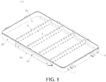
FIG. 1 is a schematic three-dimensional diagram of a battery tray according to an embodiment of the present disclose; -
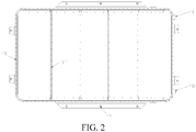
FIG. 2 is a top view of the battery tray inFIG. 1 ; -
FIG. 3 is a top exploded view of a battery module, a gasket, and a partition plate in the battery tray inFIG. 1 ; -
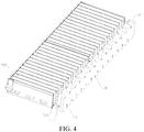
FIG. 4 is a three-dimensional exploded view of a battery module, a gasket, and a partition plate in the battery tray inFIG. 1 ; -
FIG. 5 is a schematic three-dimensional diagram of a battery tray according to another embodiment of the present disclose; -
FIG. 6 is a schematic three-dimensional diagram of the battery tray inFIG. 5 , where a gasket is also shown; -
FIG. 7 is a schematic top view of the battery tray inFIG. 5 , where a gasket is also shown; -
FIG. 8 is a three-dimensional assembled view of the battery tray inFIG. 5 and battery cells; -
FIG. 9 is a top assembled view of the battery tray inFIG. 5 and battery cells; -
FIG. 10 is a cross-sectional view taken along line A-A inFIG. 9 ; -
FIG. 11 is a schematic three-dimensional diagram of a battery tray according to another embodiment of the present disclose; -
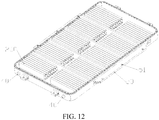
FIG. 12 is a three-dimensional assembled view of the battery tray inFIG. 11 and battery cells; -
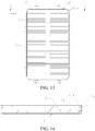
FIG. 13 is a schematic top view of the battery tray inFIG. 11 and battery cells; -
FIG. 14 is a cross-sectional view taken along line B-B inFIG. 13 ; -
FIG. 15 is a schematic three-dimensional diagram of a battery tray according to another embodiment of the present disclose; -
FIG. 16 is a schematic top view of the battery tray inFIG. 15 ; -
FIG. 17 is a cross-sectional view taken along line C-C inFIG. 16 ; -
FIG. 18 is a schematic three-dimensional diagram of a battery tray according to another embodiment of the present disclose; -
FIG. 19 is a schematic three-dimensional diagram of a battery tray according to another embodiment of the present disclose, where no inlet vent is shown; and -
FIG. 20 is a schematic structural diagram of a vehicle according to the present disclosure. - Specific implementations of the present disclosure are described in detail below with reference to the accompanying drawings. It should be understood that the specific implementations described herein are merely used to describe and explain the present disclosure, but are not intended to limit the present disclosure.
- As shown in
FIG. 1 to FIG. 20 , according to one aspect of the present disclosure, abattery tray 100 and apower battery pack 400 having thebattery tray 100 are provided. In addition to thebattery tray 100, thepower battery pack 400 may further include a cover plate (not shown) andseveral battery cells 200. The cover plate is sealedly connected to thebattery tray 100 to jointly form an enclosed space for accommodating theseveral battery cells 200. Each of thebattery cells 200 has a cell anti-explosion valve 201 (referring toFIG. 4 ). Thebattery tray 100 includes a tray body. At least a part of the tray body is formed therein with an air passage. The tray body is provided with several inlet vents 31 and at least one exhaust vent in communication with the air passage. The inlet vents 31 and thecell anti-explosion valves 201 are disposed opposite to each other and correspond one-to-one to each other. Each of the inlet vents 31 is used for introducing a flame, smoke or gas inside thebattery cell 200 into the air passage when the correspondingcell anti-explosion valve 201 is opened. The exhaust vent communicates the air passage with space outside the battery pack, and is used for discharging the flame, smoke or gas inside the air passage to the outside of the battery pack. When gas pressure inside thebattery cell 200 increases to such a degree that thecell anti-explosion valve 201 on the battery cell is opened, the flame, smoke or gas inside thebattery cell 200 is discharged to the outside of thebattery cell 200 through thecell anti-explosion valve 201, and then rushes to theinlet vent 31 and enters the air passage. - By means of the above technical solutions, once gas pressure inside a
battery cell 200 increases to such a degree that thecell anti-explosion valve 201 on the battery cell is opened, a flame, smoke or gas inside thebattery cell 200 will directly enter the air passage of the tray body through the inlet vents 31 on the tray body, so that the flame, smoke or gas does not enter the accommodating space inside the tray for thebattery cells 200, thereby preventing the flame, smoke or gas from causing secondary damage to the battery or affecting other batteries. - To prevent the flame, smoke or gas discharged from the
cell anti-explosion valve 201 from leaking into the battery accommodating space, according to some embodiments of the present disclosure, as shown inFIG. 3 ,FIG. 4 ,FIG. 6 ,FIG. 7 , andFIG. 14 , thepower battery pack 400 further includes agasket 300. Thegasket 300 is disposed between thebattery cells 200 and the tray body, is flame retardant and has certain compressibility. Thegasket 300 is provided with several throughholes 301. The throughholes 301 correspond one-to-one to the inlet vents 31 on the tray body. Each of the throughholes 301 is located between thecorresponding inlet vent 31 andcell anti-explosion valve 201. Under the compression of thebattery cells 200 and the tray body, thegasket 300 forms a seal around the inlet vents 31, to prevent the flame, smoke or gas from leaking into the battery accommodating space. - To prevent external dust and water from entering the battery accommodating space through the exhaust vent and the air passage, according to some embodiments of the present disclosure, as shown in
FIG. 1 ,FIG. 2 ,FIG. 5 to FIG. 9 ,FIG. 11 to FIG. 13 ,FIG. 17 ,FIG. 18, and FIG. 19 , thebattery tray 100 further includes a battery-pack anti-explosion valve 40. The battery-pack anti-explosion valve 40 is mounted on the exhaust vent, so that the exhaust vent is blocked by the battery-pack anti-explosion valve 40. The flame, smoke or gas discharged from thecell anti-explosion valve 201 enters and accumulates in the air passage through the inlet vents 31, and when gas pressure inside the air passage reaches a certain value, the battery-pack anti-explosion valve 40 is opened, to discharge the flame, smoke or gas that accumulates in the air passage. Herein, the battery-pack anti-explosion valve 40 and thecell anti-explosion valve 201 are all well known to a person skilled in the art, and therefore their structures and working principles will not be described in detail herein. - In the present disclosure, the
battery tray 100 may have any suitable structure, which is not limited in the present disclosure. Several embodiments of thebattery tray 100 will be described in detail below. It should be understood that these embodiments are merely used for illustrating and explaining the present disclosure, and are not intended to limit the present disclosure. - In a first embodiment, as shown in
FIG. 1 to FIG. 4 , the tray body includes abase plate 10, aside beam 20, andseveral partition plates 30. Theside beam 20 is disposed around thebase plate 10 and defines, together with thebase plate 10, the battery accommodating space. Thepartition plates 30 are disposed on thebase plate 10. Thepartition plates 30 divide thebase plate 10 into several regions for placing thebattery cells 200. Thepartition plates 30 and theside beam 20 are each formed therein with an air passage and are in communication with each other. The inlet vents 31 are provided on thepartition plates 30. The at least one exhaust vent is provided on theside beam 20. In this embodiment, the flame, smoke or gas discharged from thecell anti-explosion valve 201 enters the air passages in thepartition plates 30 through the inlet vents 31 on thepartition plates 30, and then diffuses into the air passage in theside beam 20 from the air passages in thepartition plates 30. When gas pressure inside the air passage reaches a certain value, the battery-pack anti-explosion valve 40 on theside beam 20 is opened, so that the flame, smoke or gas that accumulates in the air passage is discharged to the outside of the battery pack through the battery-pack anti-explosion valve 40. - In the first embodiment, as shown in
FIG. 3 andFIG. 4 , a plurality ofbattery cells 200 form a battery module.Gaskets 300 are disposed between the battery module and thepartition plates 30. Each of thegaskets 300 is provided with several throughholes 301. The throughholes 301 correspond one-to-one to the inlet vents 31 on thepartition plates 30. Each of the throughholes 301 is located between thecorresponding inlet vent 31 andcell anti-explosion valve 201. - In a second embodiment, as shown in
FIG. 15 to FIG. 17 , the tray body includes abase plate 10, aside beam 20, andseveral partition plates 30. Theside beam 20 is disposed around thebase plate 10 and defines, together with thebase plate 10, the battery accommodating space. Thepartition plates 30 are disposed on thebase plate 10. Thepartition plates 30 divide thebase plate 10 into several regions for placing thebattery cells 200. Thepartition plates 30 and thebase plate 10 are each formed therein with an air passage and are in communication with each other. The inlet vents 31 are provided on thepartition plates 30. The at least one exhaust vent is disposed on thebase plate 10. In this embodiment, the flame, smoke or gas discharged from thecell anti-explosion valve 201 enters the air passages in thepartition plates 30 through the inlet vents 31 on thepartition plates 30, and then diffuses into the air passage in thebase plate 10 from the air passages in thepartition plates 30. When gas pressure inside the air passage reaches a certain value, the battery-pack anti-explosion valve 40 on thebase plate 10 is opened, so that the flame, smoke or gas that accumulates in the air passage is discharged to the outside of the battery pack through the battery-pack anti-explosion valve 40. - Because the top of the battery pack faces toward the passenger cabin, in the second embodiment, the exhaust vent provided on the
base plate 10 allows the gas inside the air passage to be discharged downward, which is safer. - In a third embodiment, the tray body includes a
base plate 10, aside beam 20, andseveral partition plates 30. Theside beam 20 is disposed around thebase plate 10 and defines, together with thebase plate 10, the battery accommodating space. Thepartition plates 30 are disposed on thebase plate 10. Thepartition plates 30 divide thebase plate 10 into several regions for placing thebattery cells 200. Thepartition plates 30 and theside beam 20 are each formed therein with an air passage and are in communication with each other. A part of the inlet vents 31 are provided on thepartition plates 30, and the other part of the inlet vents 31 are provided on theside beam 20. The at least one exhaust vent is provided on theside beam 20. In this embodiment, the flame, smoke or gas discharged from thecell anti-explosion valve 201 enters the air passages in thepartition plates 30 through the inlet vents 31 on thepartition plates 30; or the flame, smoke or gas discharged from thecell anti-explosion valve 201 enters the air passage in theside beam 20 through the inlet vents 31 on theside beam 20; or the flame, smoke or gas discharged from thecell anti-explosion valve 201 partially enters the air passages in thepartition plates 30 through the inlet vents 31 on thepartition plates 30, and partially enters the air passage in theside beam 20 through the inlet vents 31 on theside beam 20. When gas pressure inside the air passage reaches a certain value, the battery-pack anti-explosion valve 40 on theside beam 20 is opened, so that the flame, smoke or gas that accumulates in the air passage is discharged to the outside of the battery pack through the battery-pack anti-explosion valve 40. - In a fourth embodiment, the tray body includes a
base plate 10, aside beam 20, andseveral partition plates 30. Theside beam 20 is disposed around thebase plate 10 and defines, together with thebase plate 10, the battery accommodating space. Thepartition plates 30 are disposed on thebase plate 10. Thepartition plates 30 divide thebase plate 10 into several regions for placing thebattery cells 200. Thepartition plates 30 and thebase plate 10 are each formed therein with an air passage and are in communication with each other. A part of the inlet vents 31 are provided on thepartition plates 30, and the other part of the inlet vents 31 are provided on thebase plate 10. The at least one exhaust vent is disposed on thebase plate 10. In this embodiment, the flame, smoke or gas discharged from thecell anti-explosion valve 201 enters the air passages in thepartition plates 30 through the inlet vents 31 on thepartition plates 30, or the flame, smoke or gas discharged from thecell anti-explosion valve 201 enters the air passage in thebase plate 10 through the inlet vents 31 on thebase plate 10; or the flame, smoke or gas discharged from thecell anti-explosion valve 201 partially enters the air passages in thepartition plates 30 through the inlet vents 31 on thepartition plates 30, and partially enters the air passage in thebase plate 10 through the inlet vents 31 on thebase plate 10. When gas pressure inside the air passage reaches a certain value, the battery-pack anti-explosion valve 40 on thebase plate 10 is opened, so that the flame, smoke or gas that accumulates in the air passage is discharged to the outside of the battery pack through the battery-pack anti-explosion valve 40. - Because the top of the battery pack faces toward the passenger cabin, in the fourth embodiment, the exhaust vent provided on the
base plate 10 allows the gas inside the air passage to be discharged downward, which is safer. - In a fifth embodiment, the tray body includes a
base plate 10, aside beam 20, andseveral partition plates 30. Theside beam 20 is disposed around thebase plate 10 and defines, together with thebase plate 10, the battery accommodating space. Thepartition plates 30 are disposed on thebase plate 10. Thepartition plates 30 divide thebase plate 10 into several regions for placing thebattery cells 200. Thepartition plates 30, theside beam 20, and thebase plate 10 are each formed therein with an air passage and are in communication with each other. A part of the inlet vents 31 are provided on thepartition plates 30, a part of the inlet vents 31 are provided on theside beam 20, and the remaining part of the inlet vents 31 are provided on thebase plate 10. The at least one exhaust vent is provided on theside beam 20. In this embodiment, the flame, smoke or gas discharged from thecell anti-explosion valve 201 enters the air passages in thepartition plates 30 through the inlet vents 31 on thepartition plates 30, or enters the air passage in thebase plate 10 through the inlet vents 31 on thebase plate 10, or enters the air passage in theside beam 20 through the inlet vents 31 on theside beam 20, or enters the corresponding air passages through the inlet vents 31 on at least two of thepartition plates 30, thebase plate 10, and theside beam 20, or enters the corresponding air passages respectively through the inlet vents 31 on thepartition plates 30, thebase plate 10, and theside beam 20. When gas pressure inside the air passage reaches a certain value, the battery-pack anti-explosion valve 40 on theside beam 20 is opened, so that the flame, smoke or gas that accumulates in the air passage is discharged to the outside of the battery pack through the battery-pack anti-explosion valve 40. - In a sixth embodiment, the tray body includes a
base plate 10, aside beam 20, andseveral partition plates 30. Theside beam 20 is disposed around thebase plate 10 and defines, together with thebase plate 10, the battery accommodating space. Thepartition plates 30 are disposed on thebase plate 10. Thepartition plates 30 divide thebase plate 10 into several regions for placing thebattery cells 200. Thepartition plates 30, theside beam 20, and thebase plate 10 are each formed therein with an air passage and are in communication with each other. A part of the inlet vents 31 are provided on thepartition plates 30, a part of the inlet vents 31 are provided on theside beam 20, and the remaining part of the inlet vents 31 are provided on thebase plate 10. The at least one exhaust vent is disposed on thebase plate 10. In this embodiment, the flame, smoke or gas discharged from thecell anti-explosion valve 201 enters the air passages in thepartition plates 30 through the inlet vents 31 on thepartition plates 30, or enters the air passage in thebase plate 10 through the inlet vents 31 on thebase plate 10, or enters the air passage in theside beam 20 through the inlet vents 31 on theside beam 20, or enters the corresponding air passages through the inlet vents 31 on at least two of thepartition plates 30, thebase plate 10, and theside beam 20, or enters the corresponding air passages respectively through the inlet vents 31 on thepartition plates 30, thebase plate 10, and theside beam 20. When gas pressure inside the air passage reaches a certain value, the battery-pack anti-explosion valve 40 on thebase plate 10 is opened, so that the flame, smoke or gas that accumulates in the air passage is discharged to the outside of the battery pack through the battery-pack anti-explosion valve 40. - Because the top of the battery pack faces toward the passenger cabin, in the sixth embodiment, the exhaust vent provided on the
base plate 10 allows the gas inside the air passage to be discharged downward, which is safer. - In a seventh embodiment, the tray body includes a
base plate 10, aside beam 20, andseveral partition plates 30. Theside beam 20 is disposed around thebase plate 10 and defines, together with thebase plate 10, the battery accommodating space. Thepartition plates 30 are disposed on thebase plate 10. Thepartition plates 30 divide thebase plate 10 into several regions for placing thebattery cells 200. Thepartition plates 30, theside beam 20, and thebase plate 10 are each formed therein with an air passage and are in communication with each other. A part of the inlet vents 31 are provided on thepartition plates 30, a part of the inlet vents 31 are provided on theside beam 20, and the remaining part of the inlet vents 31 are provided on thebase plate 10. A part of the exhaust vents are provided on theside beam 20, and the other part of the exhaust vents are provided on thebase plate 10. In this embodiment, the flame, smoke or gas discharged from thecell anti-explosion valve 201 enters the air passages in thepartition plates 30 through the inlet vents 31 on thepartition plates 30, or enters the air passage in thebase plate 10 through the inlet vents 31 on thebase plate 10, or enters the air passage in theside beam 20 through the inlet vents 31 on theside beam 20, or enters the corresponding air passages through the inlet vents 31 on at least two of thepartition plates 30, thebase plate 10, and theside beam 20, or enters the corresponding air passages respectively through the inlet vents 31 on thepartition plates 30, thebase plate 10, and theside beam 20. When gas pressure inside the air passage reaches a certain value, the battery-pack anti-explosion valve 40 on thebase plate 10 is opened, or the battery-pack anti-explosion valve 40 on theside beam 20 is opened, or the battery-pack anti-explosion valves 40 on both thebase plate 10 and theside beam 20 are opened, so that the flame, smoke or gas that accumulates in the air passage is discharged to the outside of the battery pack through the battery-pack anti-explosion valve 40. - In an eighth embodiment, the tray body includes a
base plate 10, aside beam 20, andseveral partition plates 30. Theside beam 20 is disposed around thebase plate 10 and defines, together with thebase plate 10, the battery accommodating space. Thepartition plates 30 are disposed on thebase plate 10. Thepartition plates 30 divide thebase plate 10 into several regions for placing thebattery cells 200. Thepartition plates 30, theside beam 20, and thebase plate 10 are each formed therein with an air passage and are in communication with each other. The inlet vents 31 are provided on thepartition plates 30. A part of the exhaust vents are provided on theside beam 20, and the other part of the exhaust vents are provided on thebase plate 10. In this embodiment, the flame, smoke or gas discharged from thecell anti-explosion valve 201 enters the air passages in thepartition plates 30 through the inlet vents 31 on thepartition plates 30. When gas pressure inside the air passage reaches a certain value, the battery-pack anti-explosion valve 40 on thebase plate 10 is opened, or the battery-pack anti-explosion valve 40 on theside beam 20 is opened, or the battery-pack anti-explosion valves 40 on both thebase plate 10 and theside beam 20 are opened, so that the flame, smoke or gas that accumulates in the air passage is discharged to the outside of the battery pack through the battery-pack anti-explosion valve 40. - In a ninth embodiment, the tray body includes a
base plate 10, aside beam 20, andseveral partition plates 30. Theside beam 20 is disposed around thebase plate 10 and defines, together with thebase plate 10, the battery accommodating space. Thepartition plates 30 are disposed on thebase plate 10. Thepartition plates 30 divide thebase plate 10 into several regions for placing thebattery cells 200. Thepartition plates 30, theside beam 20, and thebase plate 10 are each formed therein with an air passage and are in communication with each other. A part of the inlet vents 31 are provided on thepartition plates 30, and the other part of the inlet vents 31 are provided on theside beam 20. A part of the exhaust vents are provided on theside beam 20, and the other part of the exhaust vents are provided on thebase plate 10. In this embodiment, the flame, smoke or gas discharged from thecell anti-explosion valve 201 enters the air passages in thepartition plates 30 through the inlet vents 31 on thepartition plates 30, or enters the air passage in theside beam 20 through the inlet vents 31 on theside beam 20, or partially enters the air passages in thepartition plates 30 through the inlet vents 31 on thepartition plates 30 and partially enters the air passage in theside beam 20 through the inlet vents 31 on theside beam 20. When gas pressure inside the air passage reaches a certain value, the battery-pack anti-explosion valve 40 on thebase plate 10 is opened, or the battery-pack anti-explosion valve 40 on theside beam 20 is opened, or the battery-pack anti-explosion valves 40 on both thebase plate 10 and theside beam 20 are opened, so that the flame, smoke or gas that accumulates in the air passage is discharged to the outside of the battery pack through the battery-pack anti-explosion valve 40. - In a tenth embodiment, the tray body includes a
base plate 10, aside beam 20, andseveral partition plates 30. Theside beam 20 is disposed around thebase plate 10 and defines, together with thebase plate 10, the battery accommodating space. Thepartition plates 30 are disposed on thebase plate 10. Thepartition plates 30 divide thebase plate 10 into several regions for placing thebattery cells 200. Thepartition plates 30, theside beam 20, and thebase plate 10 are each formed therein with an air passage and are in communication with each other. A part of the inlet vents 31 are provided on thepartition plates 30, and the other part of the inlet vents 31 are provided on thebase plate 10. A part of the exhaust vents are provided on theside beam 20, and the other part of the exhaust vents are provided on thebase plate 10. In this embodiment, the flame, smoke or gas discharged from thecell anti-explosion valve 201 enters the air passages in thepartition plates 30 through the inlet vents 31 on thepartition plates 30, or enters the air passage in thebase plate 10 through the inlet vents 31 on thebase plate 10, or partially enters the air passages in thepartition plates 30 through the inlet vents 31 on thepartition plates 30 and partially enters the air passage in thebase plate 10 through the inlet vents 31 on thebase plate 10. When gas pressure inside the air passage reaches a certain value, the battery-pack anti-explosion valve 40 on thebase plate 10 is opened, or the battery-pack anti-explosion valve 40 on theside beam 20 is opened, or the battery-pack anti-explosion valves 40 on both thebase plate 10 and theside beam 20 are opened, so that the flame, smoke or gas that accumulates in the air passage is discharged to the outside of the battery pack through the battery-pack anti-explosion valve 40. - In an eleventh embodiment, the tray body includes a
base plate 10, aside beam 20, andseveral partition plates 30. Theside beam 20 is disposed around thebase plate 10 and defines, together with thebase plate 10, the battery accommodating space. Thepartition plates 30 are disposed on thebase plate 10. Thepartition plates 30 divide thebase plate 10 into several regions for placing thebattery cells 200. Thepartition plates 30, theside beam 20, and thebase plate 10 are each formed therein with an air passage. The air passages in thepartition plates 30 are in communication with the air passage in theside beam 20. The air passage in theside beam 20 is in communication with the air passage in thebase plate 10. The air passages in thepartition plates 30 are in communication with the air passage in thebase plate 10 through the air passage in theside beam 20. The inlet vents 31 are provided on thepartition plates 30. The at least one exhaust vent is disposed on thebase plate 10. In this embodiment, the flame, smoke or gas discharged from thecell anti-explosion valve 201 enters the air passages in thepartition plates 30 through the inlet vents 31 on thepartition plates 30, diffuses into the air passage in theside beam 20 from the air passages in thepartition plates 30, and then diffuses into the air passage in thebase plate 10 from the air passage in theside beam 20. When gas pressure inside the air passage reaches a certain value, the battery-pack anti-explosion valve 40 on thebase plate 10 is opened, so that the flame, smoke or gas that accumulates in the air passage is discharged to the outside of the battery pack through the battery-pack anti-explosion valve 40. - In a twelfth embodiment, the tray body includes a
base plate 10, aside beam 20, andseveral partition plates 30. Theside beam 20 is disposed around thebase plate 10 and defines, together with thebase plate 10, the battery accommodating space. Thepartition plates 30 are disposed on thebase plate 10. Thepartition plates 30 divide thebase plate 10 into several regions for placing thebattery cells 200. Thepartition plates 30, theside beam 20, and thebase plate 10 are each formed therein with an air passage. The air passages in thepartition plates 30 are in communication with the air passage in thebase plate 10. The air passage in thebase plate 10 is in communication with the air passage in theside beam 20. The air passages in thepartition plates 30 are in communication with the air passage in theside beam 10 through the air passage in thebase plate 20. The inlet vents 31 are provided on thepartition plates 30. The at least one exhaust vent is provided on theside beam 20. In this embodiment, the flame, smoke or gas discharged from thecell anti-explosion valve 201 enters the air passages in thepartition plates 30 through the inlet vents 31 on thepartition plates 30, diffuses into the air passage in thebase plate 10 from the air passages in thepartition plates 30, and then diffuses into the air passage in theside beam 20 from the air passage in thebase plate 10. When gas pressure inside the air passage reaches a certain value, the battery-pack anti-explosion valve 40 on theside beam 20 is opened, so that the flame, smoke or gas that accumulates in the air passage is discharged to the outside of the battery pack through the battery-pack anti-explosion valve 40. - In a thirteenth embodiment, as shown in
FIG. 11 to FIG. 14 , the tray body includes abase plate 10 and aside beam 20. Theside beam 20 is disposed around thebase plate 10 and defines, together with thebase plate 10, the battery accommodating space. Theside beam 20 is formed therein with an air passage. The inlet vents 31 and the at least one exhaust vent are all provided on theside beam 20. In this embodiment, because the air passage is formed in theside beam 20, the flame, smoke or gas discharged from thecell anti-explosion valve 201 enters the air passage in theside beam 20 through the inlet vents 31 on theside beam 20. When gas pressure inside the air passage reaches a certain value, the battery-pack anti-explosion valve 40 on theside beam 20 is opened, so that the flame, smoke or gas that accumulates in the air passage is discharged to the outside of the battery pack through the battery-pack anti-explosion valve 40. - In the thirteenth embodiment, as shown in
FIG. 14 , a plurality ofbattery cells 200 form a battery module.Gaskets 300 are disposed between the battery module and theside beam 20. Each of thegaskets 300 is provided with several throughholes 301. The throughholes 301 correspond one-to-one to the inlet vents 31 on theside beam 20. Each of the throughholes 301 is located between thecorresponding inlet vent 31 andcell anti-explosion valve 201. - When a
battery cell 200 undergoes a thermal runaway, generally dozens of liters or even hundreds of liters of smoke or gas are generated in a short period of time. In the tenth embodiment, the configuration of both the inlet vents 31 and the at least one exhaust vent on theside beam 20 allows for a shorter gas discharge path, so that the smoke or gas can be discharged more quickly, thereby improving the safety performance of the battery pack. - In a fourteenth embodiment, as shown in
FIG. 5 to FIG. 10 , the tray body includes abase plate 10 and aside beam 20. Theside beam 20 is disposed around thebase plate 10 and defines, together with thebase plate 10, the battery accommodating space. Thebase plate 10 is formed therein with an air passage. The inlet vents 31 and the at least one exhaust vent are all provided on thebase plate 10. In this embodiment, because the air passage is formed in thebase plate 10, the flame, smoke or gas discharged from thecell anti-explosion valve 201 enters the air passage in thebase plate 10 through the inlet vents 31 on thebase plate 10. When gas pressure inside the air passage reaches a certain value, the battery-pack anti-explosion valve 40 on thebase plate 10 is opened, so that the flame, smoke or gas that accumulates in the air passage is discharged to the outside of the battery pack through the battery-pack anti-explosion valve 40. - In the fourteenth embodiment, as shown in
FIG. 6 andFIG. 7 , a plurality ofbattery cells 200 form a battery module.Gaskets 300 are disposed between the battery module and theside beam 20. Each of thegaskets 300 is provided with several throughholes 301. The throughholes 301 correspond one-to-one to the inlet vents 31 on thebase plate 10. Each of the throughholes 301 is located between thecorresponding inlet vent 31 andcell anti-explosion valve 201. - When a
battery cell 200 undergoes a thermal runaway, generally dozens of liters or even hundreds of liters of smoke or gas are generated in a short period of time. In the fourteenth embodiment, the configuration of both the inlet vents 31 and the at least one exhaust vent on thebase plate 10 allows for a shorter gas discharge path, so that the smoke or gas can be discharged more quickly, thereby improving the safety performance of the battery pack. - Because the top of the battery pack faces toward the passenger cabin, in the fourteenth embodiment, the exhaust vent provided on the
base plate 10 allows the gas inside the air passage to be discharged downward, which is safer. - In a fifteenth embodiment, as shown in
FIG. 18 , the tray body includes abase plate 10 and aside beam 20. Theside beam 20 is disposed around thebase plate 10 and defines, together with thebase plate 10, the battery accommodating space. Theside beam 20 and thebase plate 10 are each formed therein with an air passage and are in communication with each other. The inlet vents 31 are provided on thebase plate 10. The at least one exhaust vent is provided on theside beam 20. In this embodiment, the flame, smoke or gas discharged from thecell anti-explosion valve 201 enters the air passage in thebase plate 10 through the inlet vents 31 on thebase plate 10, and then diffuses into the air passage in theside beam 20 from the air passage in thebase plate 10. When gas pressure inside the air passage reaches a certain value, the battery-pack anti-explosion valve 40 on theside beam 20 is opened, so that the flame, smoke or gas that accumulates in the air passage is discharged to the outside of the battery pack through the battery-pack anti-explosion valve 40. - In a sixteenth embodiment, the tray body includes a
base plate 10 and aside beam 20. Theside beam 20 is disposed around thebase plate 10 and defines, together with thebase plate 10, the battery accommodating space. Theside beam 20 and thebase plate 10 are each formed therein with an air passage and are in communication with each other. The inlet vents 31 are provided on theside beam 20. The at least one exhaust vent is disposed on thebase plate 10. In this embodiment, the flame, smoke or gas discharged from thecell anti-explosion valve 201 enters the air passage in theside beam 20 through the inlet vents 31 on theside beam 20, and then diffuses into the air passage in thebase plate 10 from the air passage in theside beam 20. When gas pressure inside the air passage reaches a certain value, the battery-pack anti-explosion valve 40 on thebase plate 10 is opened, so that the flame, smoke or gas that accumulates in the air passage is discharged to the outside of the battery pack through the battery-pack anti-explosion valve 40. - In the present disclosure, the
battery tray 100 may be rectangular, including arectangular base plate 10 and aside beam 20 disposed around thebase plate 10. Theside beam 20 and thebase plate 10 may be made an integral structure, or may be made a split-type structure. For example, theside beam 20 is mounted around the base plate by soldering or other processes. Theside beam 20 may be an integral structure, and may be formed by fourside beams 20 soldered head-to-tail or connected by other processes. Thepartition plates 30 and thebase plate 10 may be made an integral structure, or may be made a split-type structure. For example, thepartition plates 30 are connected to thebase plate 10 by soldering or other processes. - In the above first to twelfth embodiments, the
partition plates 30 are disposed inside thebattery tray 100, thepartition plates 30 function to reinforce thebattery tray 100, and at least a part of the inlet vents 31 are provided on thepartition plates 30. In the above thirteenth to sixteenth embodiments, whether to dispose partition plates inside the battery tray is not particularly limited. There may be nopartition plate 30 disposed inside the battery tray, in which case the inlet vents 31 may be directly provided on theside beam 20, or directly provided on thebase plate 10, or directly provided on theside beam 20 and thebase plate 10. - In the above first to twelfth embodiments, the
partition plates 30 may be arranged in the battery tray based on any suitable arrangement manner, which is not limited in the present disclosure. According to some embodiments of the present disclosure, as shown inFIG. 1 andFIG. 2 , thepartition plates 30 may be parallel to and spaced apart from each other, thepartition plates 30 are perpendicular to thebase plate 10, and two ends of each of thepartition plates 30 are connected to theside beam 20. According to some embodiments of the present disclosure, as shown inFIG. 19 , thepartition plates 30 may include one or morelongitudinal partition plates 31 extending along a length direction of the tray body and one or moretransverse partition plates 32 extending along a width direction of the tray body. Thelongitudinal partition plate 31 and thetransverse partition plate 32 cross each other. Two ends of thelongitudinal partition plate 31 are connected to theside beam 20. Two ends of thetransverse partition plate 32 are connected to theside beam 20. - In the present disclosure, the air passage formed inside the tray body is used for receiving and storing the flame, smoke or gas discharged from the
battery cells 200, the flame, smoke or gas discharged from all thebattery cells 200 can enter the air passage through the corresponding inlet vents 31, and the battery-pack anti-explosion valve 40 is used for controlling the discharging of gas from the air passage. - The number of air passages is not limited in the present disclosure. Each
battery cell 200 may correspond to one air passage, or a plurality ofbattery cells 200 may share one air passage. - In the above first embodiment, the
side beam 20 may be formed therein with one air passage, and the air passage is in communication with the air passage in each of thepartition plates 30; or theside beam 20 may be formed therein with a plurality of air passages independent of each other, and the air passage in each of thepartition plates 30 is in communication with only the corresponding air passage in theside beam 20. - In the above second embodiment, the
base plate 10 may be formed therein with one air passage, and the air passage is in communication with the air passage in each of thepartition plates 30; or thebase plate 10 may be formed therein with a plurality of air passages independent of each other, and the air passage in each of thepartition plates 30 is in communication with only the corresponding air passage in thebase plate 10. - In the above thirteenth embodiment, the
side beam 20 may be formed therein with one air passage, and all thebattery cells 200 share the air passage, i.e., the inlet vents 31 and the at least one exhaust vent are all in communication with the air passage; or theside beam 20 may be formed therein with a plurality of air passages independent of each other, and each of the air passages corresponds to a plurality ofbattery cells 200, i.e., each of the air passages has a plurality of inlet vents 31 and at least one exhaust vent; or theside beam 20 may be formed therein with a plurality of air passages independent of each other, and each of the air passages corresponds to onebattery cell 200, i.e., each of the air passages has oneinlet vent 31 and one exhaust vent. - In the above fourteenth embodiment, the
base plate 10 may be formed therein with one air passage, and all thebattery cells 200 share the air passage, i.e., the inlet vents 31 and the at least one exhaust vent are all in communication with the air passage; or thebase plate 10 may be formed therein with a plurality of air passages independent of each other, and each of the air passages corresponds to a plurality ofbattery cells 200, i.e., each of the air passages has a plurality of inlet vents 31 and at least one exhaust vent; or thebase plate 10 may be formed therein with a plurality of air passages independent of each other, and each of the air passages corresponds to onebattery cell 200, i.e., each of the air passages has oneinlet vent 31 and one exhaust vent. - In the present disclosure, according to some embodiments of the present disclosure, each of the air passages corresponds to a plurality of
battery cells 200, that is to say, a plurality ofbattery cells 200 may share one air passage, which can reduce the number of exhaust vents and the number of battery-pack anti-explosion valves 40, so that the number of exhaust vents and the number of battery-pack anti-explosion valves 40 can be less than the number of inlet vents 31, thereby reducing the processing difficulty of the tray body, reducing the number of battery-pack anti-explosion valves 40 required, and reducing the manufacturing costs. According to some embodiments of the present disclosure, the number of battery-pack anti-explosion valves 40 may be one, two, three or more, which is not limited in the present disclosure. - In the above first and second embodiments, as shown in
FIG. 3 andFIG. 4 , the number ofgaskets 300 may be the same as the number ofpartition plates 30, thegaskets 300 correspond one-to-one to thepartition plates 30, and each of thegasket 300 is disposed between thecorresponding partition plate 30 andbattery cell 200. Thegaskets 300 may be integrally formed, or may be disposed separately. In an embodiment, the gaskets are disposed separately, so as to match the use of battery modules having different numbers ofbattery cells 200. The material of the gaskets is not particularly limited in the present disclosure, which specifically may be one or a combination of a polyurethane foam material, a silicone foam, and a flame-retardant polypropylene foam material. - In the present disclosure, as shown in
FIG. 2 , an upper edge of theside beam 20 may be provided with a plurality of first mountingholes 21, and bolts pass through the first mountingholes 21 and are connected to the cover plate, so as to achieve the connection between theside beam 20 and the cover plate. In the above first to fifth embodiments, as shown inFIG. 2 , upper edges of thepartition plates 30 may be flush with an upper edge of theside beam 20, the upper edges of thepartition plates 30 may be provided with second mounting holes 32, and bolts pass through the second mounting holes 32 and are connected to the cover plate, so as to achieve the connection between thepartition plates 30 and the cover plate. - In the present disclosure, as shown in
FIG. 2 , one ormore mounting blocks 50 may be disposed on an outer side of theside beam 20, one or more third mountingholes 51 are provided on the mounting blocks 50, and bolts pass through the third mounting holes 51 and are connected to the bottom of avehicle 500, so as to fix thebattery tray 100 to the bottom of thevehicle 500. - In the prior art, a smoke sensor or a gas sensor is disposed inside the battery tray, and when a
battery cell 200 relatively distant from the smoke sensor or the gas sensor undergoes a thermal runaway and the anti-explosion valve is opened to release the gas or smoke, the large volume of the tray causes the released gas or smoke to diffuse inside the battery tray and thus be diluted, and consequently the smoke sensor or the gas sensor may be unable to detect the released gas or smoke in time, resulting in a decrease in sensitivity. In contrast, in the present disclosure, a smoke sensor or a gas sensor (not shown) may be disposed in the air passage of thebattery tray 100, the space of the air passage is obviously smaller than the volume of the battery tray, and the air passage discharges the corresponding smoke or gas along a predetermined direction. Therefore, once acell anti-explosion valve 201 is opened, the smoke sensor or the gas sensor senses the corresponding smoke or gas, and the smoke sensor or the gas sensor feeds back a signal to a vehicle control system, to caution the user to make a response or start gaseous fire suppression or other actions of the battery pack, thereby improving the safety performance of the battery pack. The positions at which the smoke sensor and the gas sensor are disposed inside the air passage and the numbers of smoke sensors and gas sensors are not particularly limited in the present disclosure. In an embodiment, the smoke is disposed close to the position of the exhaust vent, or the gas sensor is disposed close to the position of the exhaust vent, or both the smoke sensor and the gas sensor are disposed close to the position of the exhaust vent, so that the corresponding gas or smoke can be detected more sensitively. - According to another aspect of the present disclosure, a
vehicle 500 is provided. Thevehicle 500 includes the above-mentionedpower battery pack 400. - The implementations of the present disclosure are described in detail above with reference to the accompanying drawings. However, the present disclosure is not limited to the specific details in the foregoing implementations, a plurality of simple deformations may be made to the technical solution of the present disclosure within a range of the technical concept of the present disclosure, and these simple deformations fall within the protection scope of the present disclosure.
- It should be additionally noted that, the specific technical features described in the foregoing specific implementations may be combined in any proper manner in a case without conflict. To avoid unnecessary repetition, various possible combination manners are not described in the present disclosure.
- In addition, different implementations of the present disclosure may also be arbitrarily combined without departing from the idea of the present disclosure, and these combinations shall still be regarded as content disclosed in the present disclosure.
| 100: battery tray | 10: base plate |
| 20: side beam | 21: first mounting hole |
| 30: partition plate | 31: inlet vent |
| 32: second mounting hole | 40: battery-pack anti-explosion valve |
| 50: mounting block | 51: third mounting hole |
| 200: battery cell | 201: cell anti-explosion valve |
| 300: gasket | 301: through hole |
| 400: power battery pack | 500: vehicle. |
Claims (18)
- A power battery pack, comprising a battery tray (100) and several battery cells (200) disposed on the battery tray (100), wherein each of the battery cells (200) has a cell anti-explosion valve (201), the battery tray (100) comprises a tray body, at least a part of the tray body is formed therein with an air passage, the tray body is provided with several inlet vents (31) and at least one exhaust vent, at least part of the inlet vents (31) and the cell anti-explosion valves (201) are disposed opposite to each other and correspond one-to-one to each other so that a flame, smoke or gas discharged from each of the cell anti-explosion valves (201) enters the air passage through the corresponding inlet vent (31), and the exhaust vent is configured to discharge the flame, smoke or gas inside the air passage.
- The power battery pack according to claim 1, wherein at least a part of the tray body is a hollow structure, and the hollow structure serves as the air passage.
- The power battery pack according to claim 1 or 2, wherein the battery tray (100) further comprises a battery-pack anti-explosion valve (40), and the exhaust vent is blocked by the battery-pack anti-explosion valve (40).
- The power battery pack according to any one of claims 1-3, wherein the tray body comprises a base plate (10) and a side beam (20), the side beam (20) is disposed around the base plate (10) and defines, together with the base plate (10), an accommodating space for the battery cells (200), the side beam (20) is formed therein with an air passage, and the inlet vents (31) and the at least one exhaust vent are all provided on the side beam (20).
- The power battery pack according to any one of claims 1-3, wherein the tray body comprises a base plate (10) and a side beam (20), the side beam (20) is disposed around the base plate (10) and defines, together with the base plate (10), an accommodating space for the battery cells (200), the side beam (20) and the base plate (10) are each formed therein with an air passage and are in communication with each other, the inlet vents (31) are provided on the side beam (20), and the at least one exhaust vent is provided on the base plate (10).
- The power battery pack according to any one of claims 1-3, wherein the tray body comprises a base plate (10) and a side beam (20), the side beam (20) is disposed around the base plate (10) and defines, together with the base plate (10), an accommodating space for the battery cells (200), the base plate(10) is formed therein with an air passage, and the inlet vents (31) and the at least one exhaust vent are all provided on the base plate (10).
- The power battery pack according to any one of claims 1-3, wherein the tray body comprises a base plate (10) and a side beam (20), the side beam (20) is disposed around the base plate (10) and defines, together with the base plate (10), an accommodating space for the battery cells (200), the side beam (20) and the base plate (10) are each formed therein with an air passage and are in communication with each other, the inlet vents (31) are provided on the base plate (10), and the at least one exhaust vent is provided on the side beam (20).
- The power battery pack according to any one of claims 1-3, wherein the tray body comprises a base plate (10), a side beam (20), and several partition plates (30), the side beam (20) is disposed around the base plate (10) and defines, together with the base plate (10), an accommodating space for the battery cells (200), the partition plates (30) are disposed on the base plate (10) and divide the base plate (10) into several regions for placing the battery cells (200), the partition plates (30) and the side beam (20) are each formed therein with an air passage and are in communication with each other, the inlet vents (31) are provided on the partition plates (30), and the at least one exhaust vent is provided on the side beam (20).
- The power battery pack according to any one of claims 1-3, wherein the tray body comprises a base plate (10), a side beam (20), and several partition plates (30), the side beam (20) is disposed around the base plate (10) and defines, together with the base plate (10), an accommodating space for the battery cells (200), the partition plates (30) are disposed on the base plate (10) and divide the base plate (10) into several regions for placing the battery cells (200), the partition plates (30) and the base plate (10) are each formed therein with an air passage and are in communication with each other, the inlet vents (31) are provided on the partition plates (30), and the at least one exhaust vent is provided on the base plate (10).
- The power battery pack according to any one of claims 1-3, wherein the tray body comprises a base plate (10), a side beam (20), and several partition plates (30), the side beam (20) is disposed around the base plate (10) and defines, together with the base plate (10), an accommodating space for the battery cells (200), the partition plates (30) are disposed on the base plate (10) and divide the base plate (10) into several regions for placing the battery cells (200), the partition plates (30), the side beam (20), and the base plate (10) are each formed therein with an air passage, the air passages in the partition plates (30) are in communication with the air passage in the side beam (20), the air passage in the side beam (20) is in communication with the air passage in the base plate (10), the inlet vents (31) are provided on the partition plates (30), and the at least one exhaust vent is provided on the base plate (10).
- The power battery pack according to any one of claims 1-3, wherein the tray body comprises a base plate (10), a side beam (20), and several partition plates (30), the side beam (20) is disposed around the base plate (10) and defines, together with the base plate (10), an accommodating space for the battery cells (200), the partition plates (30) are disposed on the base plate (10) and divide the base plate (10) into several regions for placing the battery cells (200), the partition plates (30), the side beam (20), and the base plate (10) are each formed therein with an air passage, the air passages in the partition plates (30) are in communication with the air passage in the base plate (10), the air passage in the base plate (10) is in communication with the air passage in the side beam (20), the inlet vents (31) are provided on the partition plates (30), and the at least one exhaust vent is provided on the side beam (20).
- The power battery pack according to any one of claims 1-3, wherein the tray body comprises a base plate (10), a side beam (20), and several partition plates (30), the side beam (20) is disposed around the base plate (10) and defines, together with the base plate (10), an accommodating space for the battery cells (200), the partition plates (30) are disposed on the base plate (10) and divide the base plate (10) into several regions for placing the battery cells (200), the partition plates (30) and the side beam (20) are each formed therein with an air passage and are in communication with each other, a part of the inlet vents (31) are provided on the partition plates (30), the other part of the inlet vents (31) are provided on the side beam (20), and the at least one exhaust vent is provided on the side beam (20).
- The power battery pack according to any one of claims 1-3, wherein the tray body comprises a base plate (10), a side beam (20), and several partition plates (30), the side beam (20) is disposed around the base plate (10) and defines, together with the base plate (10), an accommodating space for the battery cells (200), the partition plates (30) are disposed on the base plate (10) and divide the base plate (10) into several regions for placing the battery cells (200), the partition plates (30) and the base plate (10) are each formed therein with an air passage and are in communication with each other, a part of the inlet vents (31) are provided on the partition plates (30), the other part of the inlet vents (31) are provided on the base plate (10), and the at least one exhaust vent is provided on the base plate (10).
- The power battery pack according to any one of claims 1-3, wherein the tray body comprises a base plate (10), a side beam (20), and several partition plates (30), the side beam (20) is disposed around the base plate (10) and defines, together with the base plate (10), an accommodating space for the battery cells (200), the partition plates (30) are disposed on the base plate (10) and divide the base plate (10) into several regions for placing the battery cells (200), the partition plates (30), the side beam (20), and the base plate (10) are each formed therein with an air passage and are in communication with each other, a part of the inlet vents (31) are provided on the partition plates (30), the other part of the inlet vents (31) are provided on at least one of the side beam (20) and the base plate (10), and the at least one exhaust vent is provided on at least one of the side beam (20) and the base plate (10).
- The power battery pack according to any one of claims 1-14, wherein the battery tray (100) further comprises at least one of a smoke sensor and a gas sensor, and the at least one of the smoke sensor and the gas sensor is disposed inside the air passage.
- The power battery pack according to any one of claims 1-15, wherein the power battery pack further comprises a gasket (300), the gasket (300) is disposed between the battery cells (200) and the tray body, the gasket (300) is provided with through holes (301), the through holes (301) correspond one-to-one to the inlet vents (31), and the through hole (301) is located between the corresponding inlet vent (31) and cell anti-explosion valve (201).
- The power battery pack according to any one of claims 1-16, wherein the power battery pack further comprises a cover plate, and the cover plate is sealedly connected to the battery tray (100) to jointly form an enclosed space for accommodating the several battery cells (200).
- A vehicle, comprising the power battery pack according to any one of claims 1-17.
Applications Claiming Priority (2)
| Application Number | Priority Date | Filing Date | Title |
|---|---|---|---|
| CN201811647593.5A CN110190212B (en) | 2018-12-29 | 2018-12-29 | Power battery pack and vehicle |
| PCT/CN2019/097640 WO2020134054A1 (en) | 2018-12-29 | 2019-07-25 | Power battery pack and vehicle |
Publications (2)
| Publication Number | Publication Date |
|---|---|
| EP3905377A1 true EP3905377A1 (en) | 2021-11-03 |
| EP3905377A4 EP3905377A4 (en) | 2022-06-15 |
Family
ID=67713594
Family Applications (1)
| Application Number | Title | Priority Date | Filing Date |
|---|---|---|---|
| EP19904418.1A Pending EP3905377A4 (en) | 2018-12-29 | 2019-07-25 | Power battery pack and vehicle |
Country Status (7)
| Country | Link |
|---|---|
| US (1) | US20220123427A1 (en) |
| EP (1) | EP3905377A4 (en) |
| JP (2) | JP7377271B2 (en) |
| KR (2) | KR102662686B1 (en) |
| CN (1) | CN110190212B (en) |
| TW (1) | TWI712204B (en) |
| WO (1) | WO2020134054A1 (en) |
Cited By (13)
| Publication number | Priority date | Publication date | Assignee | Title |
|---|---|---|---|---|
| EP4064436A4 (en) * | 2020-09-30 | 2023-05-03 | Contemporary Amperex Technology Co., Limited | Battery, device, and production method and apparatus for battery |
| KR20230067109A (en) * | 2021-11-09 | 2023-05-16 | 에스케이온 주식회사 | ModulelessBattery Pack |
| CN116895886A (en) * | 2023-07-24 | 2023-10-17 | 惠州亿纬锂能股份有限公司 | battery pack |
| SE2251433A1 (en) * | 2022-12-07 | 2024-06-08 | Northvolt Ab | A battery assembly |
| US12113162B2 (en) | 2020-04-30 | 2024-10-08 | Contemporary Amperex Technology Co., Limited | Battery comprising first-type battery cell group and second-type battery cell group which are connected in series, apparatus, and method and device for manufacturing battery |
| US12132217B2 (en) | 2020-07-29 | 2024-10-29 | Contemporary Amperex Technology Co., Limited | Battery module, battery pack, apparatus, and method and device for manufacturing battery module |
| EP4369500A4 (en) * | 2022-01-12 | 2025-02-26 | Contemporary Amperex Technology (Hong Kong) Limited | Battery and electrical device |
| CN119742510A (en) * | 2024-12-25 | 2025-04-01 | 蜂巢能源科技股份有限公司 | Battery cover assembly, battery cell and battery pack |
| EP4654350A1 (en) * | 2024-05-20 | 2025-11-26 | Volvo Truck Corporation | A battery housing with ventilation channel isolating battery cells from each other |
| EP4560811A4 (en) * | 2022-08-17 | 2025-12-24 | Contemporary Amperex Technology Hong Kong Ltd | STRUCTURAL SUPPORT, HOUSING, BATTERY AND ELECTRICAL DEVICE |
| US12512548B2 (en) | 2020-04-14 | 2025-12-30 | Lg Energy Solution, Ltd. | Battery pack and device including the same |
| US12519179B2 (en) | 2020-04-14 | 2026-01-06 | Lg Energy Solution, Ltd. | Battery pack and device including the same |
| EP4611152A4 (en) * | 2023-04-19 | 2026-03-11 | Sk On Co Ltd | BATTERY RACK AND ENERGY STORAGE SYSTEM |
Families Citing this family (58)
| Publication number | Priority date | Publication date | Assignee | Title |
|---|---|---|---|---|
| WO2018022964A1 (en) | 2016-07-29 | 2018-02-01 | Crynamt Management Llc | Battery packs having structural members for improving thermal management |
| US11757149B1 (en) | 2016-09-20 | 2023-09-12 | Apple Inc. | Battery liquid quench system and methods of manufacture thereof |
| US10923788B1 (en) | 2016-11-30 | 2021-02-16 | Apple Inc. | Directed quench systems and components |
| US11870092B1 (en) | 2017-02-01 | 2024-01-09 | Apple Inc. | On-board vent gas abatement |
| US11469471B1 (en) | 2018-02-02 | 2022-10-11 | Apple Inc. | Battery pack heat dispensing systems |
| CN111384328A (en) | 2018-12-29 | 2020-07-07 | 比亚迪股份有限公司 | Battery trays, power battery packs and vehicles |
| CN110190211B (en) | 2018-12-29 | 2020-03-31 | 比亚迪股份有限公司 | Battery tray, power battery package and vehicle |
| JP2022517214A (en) | 2019-01-09 | 2022-03-07 | ビーワイディー カンパニー リミテッド | Batteries, power battery packs and electric vehicles |
| CN210110904U (en) | 2019-09-19 | 2020-02-21 | 宁德时代新能源科技股份有限公司 | Lower box, battery package and vehicle |
| CN112331997B (en) | 2019-10-15 | 2021-11-12 | 宁德时代新能源科技股份有限公司 | Battery packs and vehicles |
| KR102807685B1 (en) * | 2019-10-15 | 2025-05-13 | 주식회사 엘지에너지솔루션 | Battery Pack |
| KR102808772B1 (en) * | 2019-10-18 | 2025-05-16 | 주식회사 엘지에너지솔루션 | Apparatus For Fire Detection of Vehicle Battery and Method Thereof |
| CN111613745B (en) * | 2020-04-16 | 2022-11-08 | 宁波吉利汽车研究开发有限公司 | Power battery package and vehicle |
| CN111312964B (en) * | 2020-04-24 | 2022-01-07 | 比亚迪股份有限公司 | Battery pack and electric vehicle |
| KR102952415B1 (en) * | 2020-04-29 | 2026-04-14 | 주식회사 엘지에너지솔루션 | Battery pack with improved fixing structure and gas exhausting structure, and Electronic device and Vehicle comprising the Same |
| CN111584791A (en) * | 2020-06-22 | 2020-08-25 | 昆山宝创新能源科技有限公司 | Battery module |
| KR20220037195A (en) * | 2020-09-17 | 2022-03-24 | 에스케이온 주식회사 | Battery Pack |
| EP4064435A4 (en) * | 2020-09-30 | 2024-04-24 | Contemporary Amperex Technology Co., Limited | Battery, device, and preparation method and preparation device for battery |
| CN121238070A (en) | 2020-09-30 | 2025-12-30 | 宁德时代新能源科技股份有限公司 | Battery, device, battery preparation method and preparation device |
| CN112072046B (en) * | 2020-10-19 | 2022-12-27 | 江苏时代新能源科技有限公司 | Battery, electric device, method and equipment for preparing battery |
| EP4071911B1 (en) | 2020-10-19 | 2024-07-17 | Jiangsu Contemporary Amperex Technology Limited | Battery, power consuming device and method for producing battery |
| DE102020127589A1 (en) * | 2020-10-20 | 2022-04-21 | Bayerische Motoren Werke Aktiengesellschaft | Robust battery device and motor vehicle |
| US11764431B2 (en) | 2020-10-22 | 2023-09-19 | Apple Inc. | Battery pack structures and systems |
| KR20220065601A (en) * | 2020-11-13 | 2022-05-20 | 주식회사 엘지에너지솔루션 | Battery pack having a structure capable of swelling control and Vehicle including the same |
| CN115917861B (en) * | 2020-11-17 | 2025-02-18 | 宁德时代新能源科技股份有限公司 | Battery, device using battery, method for preparing battery, and preparation equipment |
| CN115699406B (en) | 2020-11-17 | 2024-10-01 | 宁德时代新能源科技股份有限公司 | Battery, device using battery, method for preparing battery, and preparation equipment |
| EP4044287A4 (en) | 2020-12-24 | 2022-12-28 | Contemporary Amperex Technology Co., Limited | BATTERY MODULE AND METHOD OF MANUFACTURE AND DEVICE THEREOF, BATTERY PACK AND POWER CONSUMPTION DEVICE |
| KR102823839B1 (en) * | 2021-02-08 | 2025-06-24 | 에스케이온 주식회사 | Battery Pack |
| US12609394B2 (en) * | 2021-05-25 | 2026-04-21 | Nissan Motor Co., Ltd. | Battery frame for vehicle |
| KR102929568B1 (en) * | 2021-06-17 | 2026-02-20 | 주식회사 엘지에너지솔루션 | Battery module and battery pack including the same and vehicle including the same |
| KR20230001963A (en) * | 2021-06-29 | 2023-01-05 | 주식회사 엘지에너지솔루션 | Battery pack and device including the same |
| WO2023004721A1 (en) * | 2021-07-29 | 2023-02-02 | 宁德时代新能源科技股份有限公司 | Battery, power utilization apparatus, method for preparing battery, and apparatus for preparing battery |
| ES3065086T3 (en) | 2021-07-30 | 2026-05-04 | Contemporary Amperex Technology Hong Kong Ltd | Battery group, battery pack and electric apparatus |
| KR102639671B1 (en) * | 2021-08-25 | 2024-02-21 | 주식회사 엘지에너지솔루션 | Battery module and battery pack including the same |
| US12009655B2 (en) | 2021-09-15 | 2024-06-11 | Apple Inc. | Switchable pyro fuse |
| CN218005072U (en) * | 2021-11-30 | 2022-12-09 | 比亚迪股份有限公司 | Battery case, battery pack and vehicle |
| US12620672B2 (en) | 2022-02-11 | 2026-05-05 | Eve Power Co., Ltd. | Battery module and electric vehicle |
| US20240380066A1 (en) * | 2022-06-03 | 2024-11-14 | Lg Energy Solution, Ltd. | Battery pack |
| KR20230167969A (en) * | 2022-06-03 | 2023-12-12 | 주식회사 엘지에너지솔루션 | Battery pack |
| EP4376189A4 (en) * | 2022-07-20 | 2025-09-10 | Lg Energy Solution Ltd | BATTERY PACK AND CELL BLOCK CONTAINED THEREIN AND VEHICLE THEREOF |
| CN115295946B (en) * | 2022-08-16 | 2024-07-16 | 小米汽车科技有限公司 | Battery Pack and Thermal Runaway Protection Design Method |
| US20240079717A1 (en) * | 2022-09-02 | 2024-03-07 | Ford Global Technologies, Llc | Traction battery pack venting assembly and method of establishing a traction battery pack vent path |
| KR102949021B1 (en) * | 2022-09-06 | 2026-04-03 | 주식회사 엘지에너지솔루션 | Battery pack and vehicle including the same |
| KR102951911B1 (en) * | 2022-09-30 | 2026-04-10 | 주식회사 엘지에너지솔루션 | Battery pack and vehicle including the same |
| CN219350621U (en) * | 2022-10-18 | 2023-07-14 | 宁德时代新能源科技股份有限公司 | Batteries and Consumers |
| KR20240067709A (en) * | 2022-11-09 | 2024-05-17 | 주식회사 엘지에너지솔루션 | Battery pack and Vehicle comprising the same |
| KR102757769B1 (en) * | 2022-11-18 | 2025-01-21 | 주식회사 성우하이텍 | Off-gas emission structure of battery pack case for electric vehicle |
| JP2025527613A (en) * | 2022-12-02 | 2025-08-22 | エルジー エナジー ソリューション リミテッド | Cell assembly and battery pack including same |
| JP2025519146A (en) * | 2022-12-05 | 2025-06-24 | エルジー エナジー ソリューション リミテッド | Battery pack |
| EP4475314A4 (en) * | 2022-12-21 | 2025-06-04 | LG Energy Solution, Ltd. | Battery pack and vehicle comprising same |
| KR20240135101A (en) * | 2023-03-03 | 2024-09-10 | 주식회사 엘지에너지솔루션 | Battery pack |
| KR20250014747A (en) * | 2023-07-21 | 2025-02-03 | 삼성에스디아이 주식회사 | Battery pack fire extinguishing system capable of reducing direct injection operation time and method of filling the fire extinguishing agent therefor |
| KR20250037895A (en) * | 2023-09-11 | 2025-03-19 | 주식회사 엘지에너지솔루션 | Battery pack |
| WO2025130034A1 (en) * | 2023-12-22 | 2025-06-26 | 惠州亿纬锂能股份有限公司 | Battery box body, battery pack and electrical apparatus |
| CN120237375A (en) * | 2023-12-29 | 2025-07-01 | 小米汽车科技有限公司 | Battery pack box, battery pack and electrical equipment |
| JP2025128590A (en) | 2024-02-22 | 2025-09-03 | トヨタ自動車株式会社 | Power storage device |
| CN222735271U (en) * | 2024-05-27 | 2025-04-08 | 欣旺达动力科技股份有限公司 | Battery packs and electrical equipment |
| KR20260016250A (en) * | 2024-07-26 | 2026-02-03 | 주식회사 엘지에너지솔루션 | Battery module |
Family Cites Families (31)
| Publication number | Priority date | Publication date | Assignee | Title |
|---|---|---|---|---|
| US1152247A (en) * | 1915-05-08 | 1915-08-31 | William L Walker | Battery-jar. |
| JPS593607B2 (en) * | 1977-07-21 | 1984-01-25 | 清治 皆川 | Rice field leveling machine for tractors |
| TW364221B (en) * | 1998-03-24 | 1999-07-11 | Electric Fuel Ltd | Cell for a metal-air battery |
| JP2005071917A (en) | 2003-08-27 | 2005-03-17 | Toyota Motor Corp | Battery cover and secondary battery including the cover |
| JP2007027011A (en) | 2005-07-20 | 2007-02-01 | Sanyo Electric Co Ltd | Power supply |
| JP5466906B2 (en) * | 2009-09-18 | 2014-04-09 | パナソニック株式会社 | Battery module |
| JP2012119138A (en) | 2010-11-30 | 2012-06-21 | Panasonic Corp | Battery module |
| JPWO2012073439A1 (en) * | 2010-11-30 | 2014-05-19 | パナソニック株式会社 | Battery block, battery module and battery pack arrangement structure |
| JP5420064B2 (en) | 2010-12-13 | 2014-02-19 | パナソニック株式会社 | Battery pack |
| JP5749200B2 (en) | 2011-03-30 | 2015-07-15 | テスラ・モーターズ・インコーポレーテッド | Battery pack gas exhaust system |
| DE102011079037A1 (en) * | 2011-07-12 | 2013-01-17 | Sb Limotive Company Ltd. | Battery cell module, method for operating a battery cell module and battery and motor vehicle |
| JP5903607B2 (en) * | 2011-11-11 | 2016-04-13 | パナソニックIpマネジメント株式会社 | Battery pack |
| JP6136168B2 (en) * | 2012-09-28 | 2017-05-31 | 株式会社Gsユアサ | Assembled battery |
| JP6199369B2 (en) | 2013-02-14 | 2017-09-20 | 三洋電機株式会社 | Battery module |
| CN103824984B (en) * | 2014-03-10 | 2016-05-18 | 江西博能上饶客车有限公司 | For the quick change lithium battery box assembly of new-energy automobile |
| DE102014207403A1 (en) * | 2014-04-17 | 2015-10-22 | Robert Bosch Gmbh | Battery unit with a receiving device and a plurality of electrochemical cells and battery module with a plurality of such battery units |
| CN204577542U (en) * | 2015-05-14 | 2015-08-19 | 中国科学院宁波材料技术与工程研究所 | Metal-air cell heap and battery cell thereof |
| CN204732461U (en) * | 2015-07-01 | 2015-10-28 | 深圳市慧通天下科技股份有限公司 | Anti-explosion battery box |
| CN105024112B (en) * | 2015-07-28 | 2017-09-26 | 合肥献芝新能源有限公司 | Circular strip sealing ring is without lug zinc and air cell |
| CN204857906U (en) * | 2015-07-28 | 2015-12-09 | 合肥献芝新能源有限公司 | Circular sealing washer of taking does not have empty battery of zincode ear zinc |
| KR102030726B1 (en) * | 2015-10-15 | 2019-10-10 | 주식회사 엘지화학 | Battery Pack |
| EP3316341B1 (en) | 2015-12-18 | 2019-04-10 | LG Chem, Ltd. | Battery module, battery pack including such battery module, and vehicle including such battery pack |
| KR20180006150A (en) | 2016-07-08 | 2018-01-17 | 주식회사 엘지화학 | Cell module assembly improved in safety |
| US11322793B2 (en) * | 2016-12-27 | 2022-05-03 | Panasonic Inteilectual Property Management Co., Ltd. | Battery module |
| CN206595314U (en) * | 2017-02-21 | 2017-10-27 | 广州小鹏汽车科技有限公司 | A kind of batteries of electric automobile bag pressure-relief explosion-proof structure |
| KR102172517B1 (en) * | 2017-04-04 | 2020-10-30 | 주식회사 엘지화학 | Battery Pack having crash beam structure |
| CN107482141B (en) * | 2017-07-27 | 2020-09-11 | 上海工程技术大学 | Multifunctional vehicle-mounted battery explosion-proof box |
| CN207868256U (en) * | 2017-10-26 | 2018-09-14 | 苏州宇量电池有限公司 | A kind of quick row pressure lithium battery with explosion-proof valve |
| CN207818679U (en) * | 2017-12-28 | 2018-09-04 | 宁德时代新能源科技股份有限公司 | battery module |
| CN207743264U (en) * | 2018-01-06 | 2018-08-17 | 江西安驰新能源科技有限公司 | A kind of battery modules for electric passenger vehicle |
| CN207967121U (en) * | 2018-03-30 | 2018-10-12 | 宁德时代新能源科技股份有限公司 | Battery modules |
-
2018
- 2018-12-29 CN CN201811647593.5A patent/CN110190212B/en active Active
-
2019
- 2019-07-25 WO PCT/CN2019/097640 patent/WO2020134054A1/en not_active Ceased
- 2019-07-25 EP EP19904418.1A patent/EP3905377A4/en active Pending
- 2019-07-25 KR KR1020217023460A patent/KR102662686B1/en active Active
- 2019-07-25 KR KR1020247014147A patent/KR102783830B1/en active Active
- 2019-07-25 US US17/419,464 patent/US20220123427A1/en not_active Abandoned
- 2019-07-25 JP JP2021538260A patent/JP7377271B2/en active Active
- 2019-10-30 TW TW108139356A patent/TWI712204B/en active
-
2023
- 2023-10-27 JP JP2023184360A patent/JP7731955B2/en active Active
Cited By (16)
| Publication number | Priority date | Publication date | Assignee | Title |
|---|---|---|---|---|
| US12512548B2 (en) | 2020-04-14 | 2025-12-30 | Lg Energy Solution, Ltd. | Battery pack and device including the same |
| US12519179B2 (en) | 2020-04-14 | 2026-01-06 | Lg Energy Solution, Ltd. | Battery pack and device including the same |
| US12113162B2 (en) | 2020-04-30 | 2024-10-08 | Contemporary Amperex Technology Co., Limited | Battery comprising first-type battery cell group and second-type battery cell group which are connected in series, apparatus, and method and device for manufacturing battery |
| US12272780B2 (en) | 2020-04-30 | 2025-04-08 | Contemporary Amperex Technology Co., Limited | Battery module, apparatus, battery pack, and method and device for manufacturing battery module |
| US12132217B2 (en) | 2020-07-29 | 2024-10-29 | Contemporary Amperex Technology Co., Limited | Battery module, battery pack, apparatus, and method and device for manufacturing battery module |
| EP4064436A4 (en) * | 2020-09-30 | 2023-05-03 | Contemporary Amperex Technology Co., Limited | Battery, device, and production method and apparatus for battery |
| KR20230067109A (en) * | 2021-11-09 | 2023-05-16 | 에스케이온 주식회사 | ModulelessBattery Pack |
| EP4369500A4 (en) * | 2022-01-12 | 2025-02-26 | Contemporary Amperex Technology (Hong Kong) Limited | Battery and electrical device |
| EP4560811A4 (en) * | 2022-08-17 | 2025-12-24 | Contemporary Amperex Technology Hong Kong Ltd | STRUCTURAL SUPPORT, HOUSING, BATTERY AND ELECTRICAL DEVICE |
| US12603385B2 (en) | 2022-08-17 | 2026-04-14 | Contemporary Amperex Technology (Hong Kong) Limited | Structural beam, box, battery, and electric device |
| SE546756C2 (en) * | 2022-12-07 | 2025-02-18 | Northvolt Ab | A battery assembly |
| SE2251433A1 (en) * | 2022-12-07 | 2024-06-08 | Northvolt Ab | A battery assembly |
| EP4611152A4 (en) * | 2023-04-19 | 2026-03-11 | Sk On Co Ltd | BATTERY RACK AND ENERGY STORAGE SYSTEM |
| CN116895886A (en) * | 2023-07-24 | 2023-10-17 | 惠州亿纬锂能股份有限公司 | battery pack |
| EP4654350A1 (en) * | 2024-05-20 | 2025-11-26 | Volvo Truck Corporation | A battery housing with ventilation channel isolating battery cells from each other |
| CN119742510A (en) * | 2024-12-25 | 2025-04-01 | 蜂巢能源科技股份有限公司 | Battery cover assembly, battery cell and battery pack |
Also Published As
| Publication number | Publication date |
|---|---|
| CN110190212B (en) | 2020-02-04 |
| CN110190212A (en) | 2019-08-30 |
| TW202027320A (en) | 2020-07-16 |
| KR102662686B1 (en) | 2024-05-03 |
| JP7731955B2 (en) | 2025-09-01 |
| KR20240060733A (en) | 2024-05-08 |
| KR20210108442A (en) | 2021-09-02 |
| JP7377271B2 (en) | 2023-11-09 |
| JP2022516519A (en) | 2022-02-28 |
| WO2020134054A1 (en) | 2020-07-02 |
| KR102783830B1 (en) | 2025-03-21 |
| EP3905377A4 (en) | 2022-06-15 |
| TWI712204B (en) | 2020-12-01 |
| JP2024026061A (en) | 2024-02-28 |
| US20220123427A1 (en) | 2022-04-21 |
Similar Documents
| Publication | Publication Date | Title |
|---|---|---|
| US12506219B2 (en) | Battery tray and power battery pack | |
| US12555869B2 (en) | Battery tray and power battery pack | |
| US20220123427A1 (en) | Power battery pack and vehicle | |
| JP7605971B2 (en) | Battery pack with improved gas venting path | |
| CN112531246B (en) | Battery tray, power battery package and vehicle | |
| CN111668410B (en) | Power battery package and vehicle | |
| CN111668409A (en) | Battery trays, power battery packs and vehicles | |
| EP3955333A1 (en) | Upper cover assembly and battery pack | |
| KR102926488B1 (en) | Battery pack with gas venting path | |
| CN111668423A (en) | Battery modules, power battery packs and vehicles | |
| KR20250166789A (en) | Battery pack and Energy storage system including the same | |
| HK40006905A (en) | Power battery pack and vehicle | |
| HK40006905B (en) | Power battery pack and vehicle | |
| CN219959266U (en) | Battery box and battery pack | |
| EP4704237A1 (en) | Power supply equipment | |
| US20250087821A1 (en) | Apparatus for Containing Thermal Events of Energy Storage Devices | |
| CN117977098A (en) | Battery pack for vehicle and vehicle |
Legal Events
| Date | Code | Title | Description |
|---|---|---|---|
| STAA | Information on the status of an ep patent application or granted ep patent |
Free format text: STATUS: THE INTERNATIONAL PUBLICATION HAS BEEN MADE |
|
| PUAI | Public reference made under article 153(3) epc to a published international application that has entered the european phase |
Free format text: ORIGINAL CODE: 0009012 |
|
| STAA | Information on the status of an ep patent application or granted ep patent |
Free format text: STATUS: REQUEST FOR EXAMINATION WAS MADE |
|
| 17P | Request for examination filed |
Effective date: 20210729 |
|
| AK | Designated contracting states |
Kind code of ref document: A1 Designated state(s): AL AT BE BG CH CY CZ DE DK EE ES FI FR GB GR HR HU IE IS IT LI LT LU LV MC MK MT NL NO PL PT RO RS SE SI SK SM TR |
|
| RIC1 | Information provided on ipc code assigned before grant |
Ipc: H01M 50/383 20210101ALI20220124BHEP Ipc: H01M 50/249 20210101ALI20220124BHEP Ipc: H01M 50/289 20210101ALI20220124BHEP Ipc: H01M 50/35 20210101AFI20220124BHEP |
|
| DAV | Request for validation of the european patent (deleted) | ||
| DAX | Request for extension of the european patent (deleted) | ||
| REG | Reference to a national code |
Ref country code: DE Ref legal event code: R079 Free format text: PREVIOUS MAIN CLASS: H01M0002120000 Ipc: H01M0050350000 |
|
| RIC1 | Information provided on ipc code assigned before grant |
Ipc: H01M 50/383 20210101ALI20220504BHEP Ipc: H01M 50/249 20210101ALI20220504BHEP Ipc: H01M 50/289 20210101ALI20220504BHEP Ipc: H01M 50/35 20210101AFI20220504BHEP |
|
| A4 | Supplementary search report drawn up and despatched |
Effective date: 20220513 |
|
| STAA | Information on the status of an ep patent application or granted ep patent |
Free format text: STATUS: EXAMINATION IS IN PROGRESS |
|
| 17Q | First examination report despatched |
Effective date: 20250129 |