EP3905363A1 - Battery module - Google Patents
Battery module Download PDFInfo
- Publication number
- EP3905363A1 EP3905363A1 EP20855496.4A EP20855496A EP3905363A1 EP 3905363 A1 EP3905363 A1 EP 3905363A1 EP 20855496 A EP20855496 A EP 20855496A EP 3905363 A1 EP3905363 A1 EP 3905363A1
- Authority
- EP
- European Patent Office
- Prior art keywords
- harness plate
- tab
- along
- battery cell
- battery module
- Prior art date
- Legal status (The legal status is an assumption and is not a legal conclusion. Google has not performed a legal analysis and makes no representation as to the accuracy of the status listed.)
- Granted
Links
Images



Classifications
-
- H—ELECTRICITY
- H01—ELECTRIC ELEMENTS
- H01M—PROCESSES OR MEANS, e.g. BATTERIES, FOR THE DIRECT CONVERSION OF CHEMICAL ENERGY INTO ELECTRICAL ENERGY
- H01M50/00—Constructional details or processes of manufacture of the non-active parts of electrochemical cells other than fuel cells, e.g. hybrid cells
- H01M50/50—Current conducting connections for cells or batteries
- H01M50/502—Interconnectors for connecting terminals of adjacent batteries; Interconnectors for connecting cells outside a battery casing
- H01M50/503—Interconnectors for connecting terminals of adjacent batteries; Interconnectors for connecting cells outside a battery casing characterised by the shape of the interconnectors
-
- H—ELECTRICITY
- H01—ELECTRIC ELEMENTS
- H01M—PROCESSES OR MEANS, e.g. BATTERIES, FOR THE DIRECT CONVERSION OF CHEMICAL ENERGY INTO ELECTRICAL ENERGY
- H01M50/00—Constructional details or processes of manufacture of the non-active parts of electrochemical cells other than fuel cells, e.g. hybrid cells
- H01M50/20—Mountings; Secondary casings or frames; Racks, modules or packs; Suspension devices; Shock absorbers; Transport or carrying devices; Holders
- H01M50/204—Racks, modules or packs for multiple batteries or multiple cells
- H01M50/207—Racks, modules or packs for multiple batteries or multiple cells characterised by their shape
- H01M50/211—Racks, modules or packs for multiple batteries or multiple cells characterised by their shape adapted for pouch cells
-
- H—ELECTRICITY
- H01—ELECTRIC ELEMENTS
- H01M—PROCESSES OR MEANS, e.g. BATTERIES, FOR THE DIRECT CONVERSION OF CHEMICAL ENERGY INTO ELECTRICAL ENERGY
- H01M50/00—Constructional details or processes of manufacture of the non-active parts of electrochemical cells other than fuel cells, e.g. hybrid cells
- H01M50/50—Current conducting connections for cells or batteries
- H01M50/502—Interconnectors for connecting terminals of adjacent batteries; Interconnectors for connecting cells outside a battery casing
- H01M50/507—Interconnectors for connecting terminals of adjacent batteries; Interconnectors for connecting cells outside a battery casing comprising an arrangement of two or more busbars within a container structure, e.g. busbar modules
-
- H—ELECTRICITY
- H01—ELECTRIC ELEMENTS
- H01M—PROCESSES OR MEANS, e.g. BATTERIES, FOR THE DIRECT CONVERSION OF CHEMICAL ENERGY INTO ELECTRICAL ENERGY
- H01M50/00—Constructional details or processes of manufacture of the non-active parts of electrochemical cells other than fuel cells, e.g. hybrid cells
- H01M50/50—Current conducting connections for cells or batteries
- H01M50/502—Interconnectors for connecting terminals of adjacent batteries; Interconnectors for connecting cells outside a battery casing
- H01M50/519—Interconnectors for connecting terminals of adjacent batteries; Interconnectors for connecting cells outside a battery casing comprising printed circuit boards [PCB]
-
- H—ELECTRICITY
- H01—ELECTRIC ELEMENTS
- H01M—PROCESSES OR MEANS, e.g. BATTERIES, FOR THE DIRECT CONVERSION OF CHEMICAL ENERGY INTO ELECTRICAL ENERGY
- H01M50/00—Constructional details or processes of manufacture of the non-active parts of electrochemical cells other than fuel cells, e.g. hybrid cells
- H01M50/50—Current conducting connections for cells or batteries
- H01M50/543—Terminals
- H01M50/547—Terminals characterised by the disposition of the terminals on the cells
- H01M50/548—Terminals characterised by the disposition of the terminals on the cells on opposite sides of the cell
-
- H—ELECTRICITY
- H01—ELECTRIC ELEMENTS
- H01M—PROCESSES OR MEANS, e.g. BATTERIES, FOR THE DIRECT CONVERSION OF CHEMICAL ENERGY INTO ELECTRICAL ENERGY
- H01M2220/00—Batteries for particular applications
- H01M2220/20—Batteries in motive systems, e.g. vehicle, ship, plane
-
- Y—GENERAL TAGGING OF NEW TECHNOLOGICAL DEVELOPMENTS; GENERAL TAGGING OF CROSS-SECTIONAL TECHNOLOGIES SPANNING OVER SEVERAL SECTIONS OF THE IPC; TECHNICAL SUBJECTS COVERED BY FORMER USPC CROSS-REFERENCE ART COLLECTIONS [XRACs] AND DIGESTS
- Y02—TECHNOLOGIES OR APPLICATIONS FOR MITIGATION OR ADAPTATION AGAINST CLIMATE CHANGE
- Y02E—REDUCTION OF GREENHOUSE GAS [GHG] EMISSIONS, RELATED TO ENERGY GENERATION, TRANSMISSION OR DISTRIBUTION
- Y02E60/00—Enabling technologies; Technologies with a potential or indirect contribution to GHG emissions mitigation
- Y02E60/10—Energy storage using batteries
Definitions
- This application relates to the field of battery module technologies, and in particular, to a battery module.
- a harness plate is mainly used to carry electrical connectors (such as aluminum bars) and sampling harnesses, so that tabs of a battery cell unit (including positive tabs and negative tabs) are connected in series and parallel through the electrical connectors of the harness plate.
- the harness plate is in an integral structure, and the tabs of the battery cell unit need to penetrate holes of the harness plate to be connected to the electrical connectors.
- the tabs of the battery cell unit need to penetrate holes of the harness plate to be connected to the electrical connectors.
- due to features of relatively soft, deformable, and assembly tolerance of a soft-packed battery cell it is difficult to ensure that tabs of a plurality of battery cell units can penetrate the holes of the harness plate at the same time.
- the embodiments of this application provide a battery module to resolve the problem that a tab of a battery cell unit is not easy to be assembled with a harness plate.
- the embodiments of this application provide a battery module, including: a plurality of battery cell units arranged along a width direction, where each of the battery cell units has a tab, and the tab is arranged on at least one end of the battery cell unit along a length direction; and a first harness plate arranged on at least one end of the battery module along the length direction, where the first harness plate has a plurality of through grooves, and the tab passes through and is arranged on the through groove; and the through groove has an opening along a height direction, and the tab is configured to pass through and be arranged on the through groove through the opening.
- the battery module further includes a second harness plate connected to the first harness plate, where the second harness plate is arranged above or below the first harness plate along the height direction.
- the first harness plate further has a plurality of installation parts, each of the installation parts has the through grooves on both sides along the width direction; each of the installation parts is provided with an electrical connector, and the tab is connected to the electrical connector.
- the battery module further includes a second harness plate connected to the first harness plate, where the second harness plate has a plurality of through grooves; and the through groove on the second harness plate is arranged correspondingly to the through groove on the first harness plate.
- the first harness plate and the second harness plate each has a plurality of installation parts, each of the installation parts has the through grooves on both sides along the width direction; each of the installation parts is provided with an electrical connector, and the tab is connected to the electrical connector.
- the electrical connector and the first harness plate or the second harness plate provided with the installation part are integrally formed through injection molding.
- the first harness plate or the second harness plate provided with the installation part has a first surface facing away from the battery cell unit, and the electrical connector has a second surface facing away from the battery cell unit; and the second surface does not exceed the first surface along the length direction.
- an isolation part is arranged between the two installation parts, and each of the isolation parts has a protrusion; and the through groove is arranged between the installation part and the isolation part.
- an installation structure is arranged between the first harness plate and the second harness plate.
- both ends of the opening are provided with guide structures along the width direction.
- the through groove of the first harness plate has an opening along the height direction (Z), so that the tab can pass through and be arranged on the through groove through the opening.
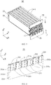
- FIG. 1 is a schematic structural diagram of a battery module according to this application
- FIG. 2 is a schematic exploded view of a battery module according to this application
- FIG. 3 is a schematic structural diagram of a battery module during harness plate assembly according to this application
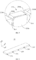
- FIG. 4 is a schematic structural diagram of a first harness plate of a battery module in FIG. 1
- FIG. 5 is an enlarged schematic diagram of A in FIG. 4
- FIG. 6 is a schematic structural diagram of a second harness plate of a battery module in FIG. 1
- FIG. 7 is a schematic structural diagram of a harness plate of a battery module in FIG. 1
- FIG. 8 is a schematic sectional view of B-B in FIG. 7
- FIG. 9 is a schematic sectional view of C-C in FIG. 7 .
- the battery module M may be used as a power source for an electric apparatus (for example, an electric vehicle).
- the battery module M includes a plurality of battery cell units 1 and first harness plates 21, where: a plurality of battery cell units 1 are arranged along a width direction (Y), each battery cell unit 1 has a tab 11, and the tab 11 is arranged on at least one end of the battery cell unit 1 along a length direction (X); a first harness plate 21 is arranged on at least one end of the battery module along the length direction (X), the first harness plate 21 has a plurality of through grooves 211, and the tab 11 can pass through the through groove 211.
- Tabs 11 are respectively bent to electrical connectors 212a (details are described later) according to the need of serial and parallel connection, and then are electrically connected to the electrical connectors 212a on the first harness plate 21 through welding (for example, laser welding).
- the electrical connector 212a is connected to an external device (such as a measuring device or other electrical devices) through a harness, to sample an internal working state of the battery module M or provide electrical energy for the external device.
- the tab 11 includes a positive tab or a negative tab.
- the tab 11 extends out of a main body of the battery cell unit 1, and the number of the first harness plates 21 depends on arrangement of the tab 11.
- a first harness plate 21 may be provided on the end (two or more harness plates may also be provided, for example, the second harness plate 22 may also be provided, details are described later);
- a first harness plate 21 may be respectively provided on each end (similarly, two or more harness plates may also be provided on each end, for example, the second harness plate 22 may also be provided, details are described later), that is, the battery module M has at least two first harness plates 21.
- the battery cell unit 1 not only includes a battery cell, for example, it may also include a thermal conductive sheet and a heat resisting sheet (not shown in the figure).
- the thermal conductive sheet is located between the battery cell and the heat resisting sheet.
- the thermal conductive sheet is punched out of a high thermal conductivity metal sheet such as red copper or pure aluminum, and the heat resisting sheet is made of heat insulating and fireproof material.
- a large surface of the battery cell is attached to the thermal conductive sheet, and a thermal conductive glue may be applied between the battery cell and the thermal conductive sheet to ensure a sufficient thermal conduction contact area.
- the other side of the thermal conductive sheet is fixedly connected with the heat resisting sheet.
- a battery cell of a next battery cell unit 1 is bonded to a heat resisting sheet of a previous battery cell unit 1.
- heat of each battery cell can only be conducted through a contacting thermal conductive sheet in the set of battery cell units 1; moreover, there must be a heat resisting sheet between thermal conductive sheets of adjacent battery cell units 1, which avoids heat transfer between different battery cells due to thermal insulation of the heat resisting sheet, thereby effectively avoiding heat diffusion between the battery cells of adjacent battery cell units 1.
- the through groove 211 has an opening 211a along a height direction (Z), and the tab 11 can pass through and be arranged on the through groove 211 through the opening 211a.
- the through groove 211 of the first harness plate 21 provided in this application has an opening 211a along the height direction (Z), so that the tab 11 can pass through and be arranged on the through groove 211 through the opening 211a.
- the harness plate is assembled with the tab in parallel along the extension direction of the tab. Because the tab is relatively soft and easily deformed, when the battery module has a plurality of battery cell units, it becomes very difficult to smoothly insert all the tabs into holes of the harness plate.
- the assembly direction of the first harness plate 21 and the tab 11 is changed, namely, assembling in a direction perpendicular to the extension direction of the tab 11.
- an installation direction (I) may be from bottom to top or from top to bottom (please refer to FIG. 3 ), which may improve assembly efficiency and a success rate of the tab and the harness plate.
- the foregoing battery module further includes a second harness plate 22 connected to the first harness plate 21, where the second harness plate 22 is arranged above or below the first harness plate 21 along the height direction (Z).
- the embodiment provided in this application is: the installation direction (I) of the first harness plate 21 is from bottom to top, and the second harness plate 22 is arranged above the first harness plate 21 along the height direction (Z).
- the second harness plate 22 may be optionally arranged above or below the first harness plate 21 along the height direction (Z) according to an actual extension position of the tab 11, and optionally, the installation direction (I) of the first harness plate 21 and the second harness plate 22 may also be from bottom to top or from top to bottom.
- first harness plate 21 and the second harness plate 22 may be collectively referred to as a harness plate 2.
- the tab 11 when the tab 11 is arranged on the end of the battery cell unit 1 along the height direction (Z), there may be only one first harness plate 21, and the through groove 211 is arranged on the end of the first harness plate 21 along the height direction (Z), so that the first harness plate 21 can be smoothly assemble with the tab 11.
- harness plates there may be two or more harness plates.
- the second harness plate 22 connected to the first harness plate 21
- This application is mainly about two harness plates (namely, the first harness plate 21 and the second harness plate 22).
- the second harness plate 22 at least serves a purpose of being separately assemble with the first harness plate 21, namely, the through groove 211 is not arranged on the second harness plate 22 (as shown in FIG. 6 ).
- the second harness plate 22 blocks the opening 211a of the through groove 211, so that the tab 11 is more stably housed in the through groove 211.
- This is also a main advantage of separate assembly of the first harness plate 21 and the second harness plate 22.
- the first harness plate 21 further has a plurality of installation parts 212, each installation part 212 has through grooves 211 on both sides along the width direction (Y); each installation part 212 is provided with an electrical connector 212a, and the tab 11 is connected to the electrical connector 212a.
- the first harness plate 21 may be made of a plastic part with high structural strength and high dielectric strength
- the electrical connector 212a may be made of a highly conductive metal such as red copper or pure aluminum, which is used for welding with the tab 11 of the battery cell unit 1, for example, laser welding.
- the second harness plate 22 also has a plurality of through grooves 211 (a through groove 211 on the second harness plate 22 is not shown in the figure), and the through groove 211 on the second harness plate 22 is arranged correspondingly to the through groove 211 on the first harness plate 21.
- the tab 11 is arranged on one of the ends of the battery cell unit 1 along the length direction (X)
- the positive tab and the negative tab are arranged up and down along the height direction (Z), so that the positive tab and the negative tab may be assembled by separately passing through the through grooves 211 on the first harness plate 21 and the second harness plate 22.
- a height of the tab 11 along the height direction (Z) exceeds a depth of the through groove 211 on the first harness plate 21 along the height direction (Z), so that after the tab 11 passes through the through groove 211 on the first harness plate 21, a part of the tab 11 may be exposed in an opening direction of the through groove 211. Therefore, a plurality of through grooves 211 arranged correspondingly to the through groove 211 on the first harness plate 21 are continued to be arranged on the second harness plate 22, so that the exposed part of the tab 11 can be housed.
- the first harness plate 21 and the second harness plate 22 each have a plurality of installation parts 212 (the installation parts 212 on the second harness plate 22 are not shown in the figure), and each installation part 212 has through grooves 211 on both sides along the width direction (Y); each installation part 212 is provided with an electrical connector 212a, and the tab 11 is connected to the electrical connector 212a.
- both the first harness plate 21 and the second harness plate 22 may be made of a plastic part with high structural strength and high dielectric strength
- the electrical connector 212a may be made of a highly conductive metal such as red copper or pure aluminum, which is used for welding with the tab 11 of the battery cell unit 1, for example, laser welding.
- one of the first harness plate 21 and the second harness plate 22 has a plurality of through grooves 211.
- the other is arranged on one side of the opening 211a, namely, keeping the opening 211a at a middle position of the battery cell unit 1 along the height direction (Z) as much as possible.
- the first harness plate 21 and the second harness plate 22 are molded in a separate manner. In this way, on the basis of improving the assembly efficiency of the tab 11, the first harness plate 21 may conform to a commonly used battery cell unit 1 on the market to a greater extent, namely, the position of the tab 11 is roughly in the middle of the battery cell unit 1.
- the electrical connector 212a and the first harness plate 21 or the second harness plate 22 provided with the installation part 212 are integrally formed through injection molding.
- the electrical connector 212a and the first harness plate 21 are integrally formed through injection molding. It may be understood that the electrical connector 212a may also be embedded in the installation part 212 after injection molding of the first harness plate 21. Of course, integral injection molding of the electrical connector 212a and the first harness plate 21 may certainly greatly improve a molding efficiency of the first harness plate 21.
- the electrical connector 212a is arranged on one side of the installation part 212 facing away from the battery cell unit 1, and the first harness plate 21 or the second harness plate 22 provided with the installation part 212 has a first surface 210 facing away from the battery cell unit 1, the electrical connector 212a has a second surface 212a1 facing away from the battery cell unit 1, and along the length direction (X), the second surface 212a1 does not exceed the first surface 210.
- the tab 11 is bent and welded to the electrical connector 212a, it is ensured that the tab 11 will not exceed the first surface 210 to the greatest extent, thereby protecting the tab 11 and improving installation compactness of the tab 11 and the first harness plate 21.
- the positive tab is made of a first material
- the negative tab is made of a second material.
- the first material and the second material are both metals, and tabs are made of different materials to avoid electrochemical corrosion.
- dissimilar metals are much more difficult to weld. Therefore, a first material foil is provided on the surface of one of the tabs as a welding surface, for example, on the surface of the negative tab, so that the negative tab can be made of the same material as the positive tab during welding.
- one of the tabs is made into a composite material plate, for example, the negative tab is made into a composite material plate having the first material and the second material, where a pure second material part of the composite material plate is encapsulated inside the battery cell unit 1, the pure first material part is a pigtail of the negative tab, and the positive tab is in the pure first material; or the positive tab is made into the composite material plate having the first material and the second material, where a pure first material part of the composite material plate is encapsulated inside the battery cell unit 1, the pure second material part is a pigtail of the positive tab, and the negative tab is in the pure second material.
- the positive tab is made of pure aluminum material and the negative tab is made of pure copper material
- a thin aluminum foil may be welded (for example, ultrasonic welding) on the surface of the negative tab as a welding surface.
- a copper-aluminum composite plate is used as the negative tab
- the pure copper part is encapsulated inside the battery cell unit 1
- the pure aluminum part is used as a pigtail of the negative tab, so that extension ends of the negative tab and the positive tab are the same pure aluminum material, which may facilitate laser welding.
- both ends of the opening 211a are provided with guide structures 211b along the width direction (Y).
- the tab 11 can be inserted into the through groove 211 smoothly through the guide structure 211b arranged at the opening 211a.
- the guide structure 211b may be an inclined surface or a circular arc surface.
- an installation structure 23 is arranged between the first harness plate 21 and the second harness plate 22, which facilitates the assembly and molding of the first harness plate 21 and the second harness plate 22.
- the installation structure 23 may at least have a buckle 231 and a buttonhole 232, where the buckle 231 is optionally arranged on the second harness plate 22, and the buttonhole 232 is arranged on the first harness plate 21.
- the buckle 231 may also be arranged on the first harness plate 21, and the buttonhole 232 is arranged on the second harness plate 22.
- the installation structure 23 may also have a pin 233 and a pin hole 234, and the installation structure 23 includes but is not limited to the above types, for example, it may also be riveted or welded.
- the first harness plate 21 and the second harness plate 22 may be fixed only by cooperation of the buckle 231 and the buttonhole 232.
- an end of the first harness plate 21 in the height direction (Z) is provided with at least one buttonhole 232 and at least one pin hole 234, and the second harness plate 22 is provided with at least one buckle 231 and at least one pin 233. Structural strength and fixing stability of the first harness plate 21 and the second harness plate 22 are increased through cooperation of the buckle 231 and the buttonhole 232, and the pin 233 and the pin hole 234.
- An isolation part 213 is arranged between two adjacent installation parts 212, and each isolation part 213 has a protrusion 213a.
- the protrusion 213a is in a plate-like structure and extends along the height direction (Z).
- a size of the protrusion 213a is not less than a size of the electrical connector 212a along the height direction (Z), which may further ensure that creepage may not occur in the tabs 11 of the two adjacent installation parts 212.
- the buttonhole 232 and the pin hole 234 may be arranged on the installation part 212 or the isolation part 213, and may also be arranged on the end of the first harness plate 21 in the height direction (Z) except for a part of the installation part 212 and the isolation part 213 (refer to FIG. 4 ).
- the pin hole 234 may be a cylindrical hole, or it may also be a truncated cone hole or a conical hole. It is not specifically limited in this application.
- the buttonhole 232 may be arranged on the installation part 212 or the isolation part 213.
- the buckle 231 has an inclination part 221a and a hook part with an inclined surface, so that the buckle 231 can be inserted into the buttonhole 232 more easily.
- FIG. 8 when the hook part is inserted into the buttonhole 232 and faces the battery cell unit 1, interference between the hook part and the electrical connector 212a may be avoided, and arrangement of the installation part 212 may be more reasonable.
- the through groove 211 of the first harness plate 21 provided in the embodiments of this application has an opening 211a along the height direction (Z), so that the tab 11 can pass through and be arranged on the through groove 211 through the opening 211a.
- an assembling direction of the harness plate namely, assembling in a direction perpendicular to an extension direction of the tab 11
- the problem that the tab of the battery cell unit is not easy to be assembled with the harness plate is resolved.
Landscapes
- Chemical & Material Sciences (AREA)
- Chemical Kinetics & Catalysis (AREA)
- Electrochemistry (AREA)
- General Chemical & Material Sciences (AREA)
- Battery Mounting, Suspending (AREA)
- Connection Of Batteries Or Terminals (AREA)
Abstract
Description
- This application claims priority to
Chinese Patent Application No. 201921353800.6, filed with the Chinese Patent Office on August 20, 2019 - This application relates to the field of battery module technologies, and in particular, to a battery module.
- A harness plate is mainly used to carry electrical connectors (such as aluminum bars) and sampling harnesses, so that tabs of a battery cell unit (including positive tabs and negative tabs) are connected in series and parallel through the electrical connectors of the harness plate.
- Generally, the harness plate is in an integral structure, and the tabs of the battery cell unit need to penetrate holes of the harness plate to be connected to the electrical connectors. However, due to features of relatively soft, deformable, and assembly tolerance of a soft-packed battery cell, it is difficult to ensure that tabs of a plurality of battery cell units can penetrate the holes of the harness plate at the same time.
- Therefore, there is an urgent need for a battery module to resolve the problem mentioned above.
- The embodiments of this application provide a battery module to resolve the problem that a tab of a battery cell unit is not easy to be assembled with a harness plate.
- The embodiments of this application provide a battery module, including:
a plurality of battery cell units arranged along a width direction, where each of the battery cell units has a tab, and the tab is arranged on at least one end of the battery cell unit along a length direction; and a first harness plate arranged on at least one end of the battery module along the length direction, where the first harness plate has a plurality of through grooves, and the tab passes through and is arranged on the through groove; and the through groove has an opening along a height direction, and the tab is configured to pass through and be arranged on the through groove through the opening. - Optionally, the battery module further includes a second harness plate connected to the first harness plate, where the second harness plate is arranged above or below the first harness plate along the height direction.
- Optionally, the first harness plate further has a plurality of installation parts, each of the installation parts has the through grooves on both sides along the width direction; each of the installation parts is provided with an electrical connector, and the tab is connected to the electrical connector.
- Optionally, the battery module further includes a second harness plate connected to the first harness plate, where the second harness plate has a plurality of through grooves; and the through groove on the second harness plate is arranged correspondingly to the through groove on the first harness plate.
- Optionally, the first harness plate and the second harness plate each has a plurality of installation parts, each of the installation parts has the through grooves on both sides along the width direction; each of the installation parts is provided with an electrical connector, and the tab is connected to the electrical connector.
- Optionally, the electrical connector and the first harness plate or the second harness plate provided with the installation part are integrally formed through injection molding.
- Optionally, the first harness plate or the second harness plate provided with the installation part has a first surface facing away from the battery cell unit, and the electrical connector has a second surface facing away from the battery cell unit; and the second surface does not exceed the first surface along the length direction.
- Optionally, an isolation part is arranged between the two installation parts, and each of the isolation parts has a protrusion; and the through groove is arranged between the installation part and the isolation part.
- Optionally, an installation structure is arranged between the first harness plate and the second harness plate.
- Optionally, both ends of the opening are provided with guide structures along the width direction.
- The technical solutions provided in the embodiments of this application have the following beneficial effects:
In the battery module provided in the embodiments of this application, the through groove of the first harness plate has an opening along the height direction (Z), so that the tab can pass through and be arranged on the through groove through the opening. Thus, by changing an assembling direction of the harness plate (namely, assembling in a direction perpendicular to an extension direction of the tab), the problem that the tab of the battery cell unit is not easy to be assembled with the harness plate is resolved. - It should be understood that the general description above and the following details are only exemplary and cannot limit this application.
-
-
FIG. 1 is a schematic structural diagram of a battery module according to an embodiment of this application; -
FIG. 2 is a schematic exploded view of a battery module according to an embodiment of this application; -
FIG. 3 is a schematic structural diagram of a battery module during harness plate assembly according to an embodiment of this application; -
FIG. 4 is a schematic structural diagram of a first harness plate of a battery module inFIG. 1 according to an embodiment of this application; -
FIG. 5 is an enlarged schematic diagram of A inFIG. 4 ; -
FIG. 6 is a schematic structural diagram of a second harness plate of a battery module inFIG. 1 according to an embodiment of this application; -
FIG. 7 is a schematic structural diagram of a harness plate of a battery module inFIG. 1 according to an embodiment of this application; -
FIG. 8 is a schematic sectional view of B-B inFIG. 7 ; -
FIG. 9 is an enlarged schematic diagram of D inFIG. 8 ; and -
FIG. 10 is a schematic sectional view of C-C inFIG. 7 . -
- M-battery module;
- 1-battery cell unit;
- 11-tab;
- 2-harness plate;
- 21-first harness plate;
- 210-first surface;
- 211-through groove;
- 211a-opening;
- 211b-guide structure;
- 212-installation part;
- 212a-electrical connector;
- 212a1-second surface;
- 213-isolation part;
- 213a-protrusion;
- 22-second harness plate;
- 23-installation structure;
- 231- buckle;
- 232-buttonhole;
- 233-pin;
- 234-pin hole;
- X-length direction;
- Y-width direction;
- Z-height direction;
- I-installation direction.
- The drawings herein are incorporated into the specification and constitute a part of the specification, showing embodiments that conform to this application, and are used with the specification to explain principles of this application.
- To make objectives, technical solutions, and advantages of this application clearer, the following further describes this application in detail with reference to the accompanying drawings and embodiments. It should be understood that the specific embodiments described herein are only used to explain this application, and are not used to limit this application.
- In the description of this application, unless expressly stipulated and limited otherwise, terms "first" and "second" are only used for descriptive purposes, and cannot be understood as indicating or implying relative importance; unless otherwise stipulated or stated, the term "a plurality of" refers to two or more; terms "connected", "fixed", and the like should be understood in a broad sense. For example, "connected" may be a fixed connection, a detachable connection, or an integral connection, or electrical connection; it may be directly connected or indirectly connected through an intermediate medium. For those skilled in the art, the specific meaning of the above terms in the present invention can be understood according to the specific circumstances.
- In the description of this specification, it should be understood that the noun of locality such as "upper" and "lower" described in the embodiments of this application are described from the angle shown in the accompanying drawings, and should not be understood as a limitation to the embodiments of this application. In addition, in the context, it should also be understood that when referring to that an element is connected "on" or "under" another element, it can not only be directly connected "on" or "under" another element, but also be indirectly connected "on" or "under" another element through an intermediate element.
-
FIG. 1 is a schematic structural diagram of a battery module according to this application;FIG. 2 is a schematic exploded view of a battery module according to this application;FIG. 3 is a schematic structural diagram of a battery module during harness plate assembly according to this application;FIG. 4 is a schematic structural diagram of a first harness plate of a battery module inFIG. 1 ;FIG. 5 is an enlarged schematic diagram of A inFIG. 4 ;FIG. 6 is a schematic structural diagram of a second harness plate of a battery module inFIG. 1 ;FIG. 7 is a schematic structural diagram of a harness plate of a battery module inFIG. 1 ;FIG. 8 is a schematic sectional view of B-B inFIG. 7 ; andFIG. 9 is a schematic sectional view of C-C inFIG. 7 . - As shown in
FIG. 1 to FIG. 3 , the battery module M may be used as a power source for an electric apparatus (for example, an electric vehicle). The battery module M includes a plurality ofbattery cell units 1 andfirst harness plates 21, where:
a plurality ofbattery cell units 1 are arranged along a width direction (Y), eachbattery cell unit 1 has atab 11, and thetab 11 is arranged on at least one end of thebattery cell unit 1 along a length direction (X); afirst harness plate 21 is arranged on at least one end of the battery module along the length direction (X), thefirst harness plate 21 has a plurality of throughgrooves 211, and thetab 11 can pass through the throughgroove 211.Tabs 11 are respectively bent toelectrical connectors 212a (details are described later) according to the need of serial and parallel connection, and then are electrically connected to theelectrical connectors 212a on thefirst harness plate 21 through welding (for example, laser welding). Theelectrical connector 212a is connected to an external device (such as a measuring device or other electrical devices) through a harness, to sample an internal working state of the battery module M or provide electrical energy for the external device. - The
tab 11 includes a positive tab or a negative tab. Thetab 11 extends out of a main body of thebattery cell unit 1, and the number of thefirst harness plates 21 depends on arrangement of thetab 11. For example, when a pair oftabs 11 of thebattery cell unit 1 is on one of the ends, afirst harness plate 21 may be provided on the end (two or more harness plates may also be provided, for example, thesecond harness plate 22 may also be provided, details are described later); when the pair oftabs 11 of thebattery cell unit 1 are respectively located on both ends of thebattery cell unit 1 along the length direction (X), afirst harness plate 21 may be respectively provided on each end (similarly, two or more harness plates may also be provided on each end, for example, thesecond harness plate 22 may also be provided, details are described later), that is, the battery module M has at least twofirst harness plates 21. - It may be understood that the
battery cell unit 1 provided in this application not only includes a battery cell, for example, it may also include a thermal conductive sheet and a heat resisting sheet (not shown in the figure). The thermal conductive sheet is located between the battery cell and the heat resisting sheet. Optionally, the thermal conductive sheet is punched out of a high thermal conductivity metal sheet such as red copper or pure aluminum, and the heat resisting sheet is made of heat insulating and fireproof material. A large surface of the battery cell is attached to the thermal conductive sheet, and a thermal conductive glue may be applied between the battery cell and the thermal conductive sheet to ensure a sufficient thermal conduction contact area. The other side of the thermal conductive sheet is fixedly connected with the heat resisting sheet. In a combination of a set of arrangedbattery cell units 1, a battery cell of a nextbattery cell unit 1 is bonded to a heat resisting sheet of a previousbattery cell unit 1. In this way, heat of each battery cell can only be conducted through a contacting thermal conductive sheet in the set ofbattery cell units 1; moreover, there must be a heat resisting sheet between thermal conductive sheets of adjacentbattery cell units 1, which avoids heat transfer between different battery cells due to thermal insulation of the heat resisting sheet, thereby effectively avoiding heat diffusion between the battery cells of adjacentbattery cell units 1. - Please refer to
FIG. 4 andFIG. 5 , the throughgroove 211 has anopening 211a along a height direction (Z), and thetab 11 can pass through and be arranged on the throughgroove 211 through theopening 211a. The throughgroove 211 of thefirst harness plate 21 provided in this application has anopening 211a along the height direction (Z), so that thetab 11 can pass through and be arranged on the throughgroove 211 through theopening 211a. Thus, by changing an assembling direction of the harness plate (namely, assembling in a direction perpendicular to an extension direction of the tab 11), the problem that the tab of the battery cell unit is not easy to be assembled with the harness plate is resolved. - In other words, in related technologies, the harness plate is assembled with the tab in parallel along the extension direction of the tab. Because the tab is relatively soft and easily deformed, when the battery module has a plurality of battery cell units, it becomes very difficult to smoothly insert all the tabs into holes of the harness plate. However, in the embodiment provided in this application, the assembly direction of the
first harness plate 21 and thetab 11 is changed, namely, assembling in a direction perpendicular to the extension direction of thetab 11. For example, an installation direction (I) may be from bottom to top or from top to bottom (please refer toFIG. 3 ), which may improve assembly efficiency and a success rate of the tab and the harness plate. - Specifically, the foregoing battery module further includes a
second harness plate 22 connected to thefirst harness plate 21, where thesecond harness plate 22 is arranged above or below thefirst harness plate 21 along the height direction (Z). Optionally, the embodiment provided in this application is: the installation direction (I) of thefirst harness plate 21 is from bottom to top, and thesecond harness plate 22 is arranged above thefirst harness plate 21 along the height direction (Z). In other words, thesecond harness plate 22 may be optionally arranged above or below thefirst harness plate 21 along the height direction (Z) according to an actual extension position of thetab 11, and optionally, the installation direction (I) of thefirst harness plate 21 and thesecond harness plate 22 may also be from bottom to top or from top to bottom. - It should be noted that the
first harness plate 21 and thesecond harness plate 22 may be collectively referred to as aharness plate 2. - It may be understood that when the
tab 11 is arranged on the end of thebattery cell unit 1 along the height direction (Z), there may be only onefirst harness plate 21, and the throughgroove 211 is arranged on the end of thefirst harness plate 21 along the height direction (Z), so that thefirst harness plate 21 can be smoothly assemble with thetab 11. - It may be further understood that there may be two or more harness plates. For example, besides the
first harness plate 21, there may be thesecond harness plate 22 connected to thefirst harness plate 21, and there may also be a third harness plate, a fourth harness plate (not shown in the figure), and the like connected to thefirst harness plate 21 or thesecond harness plate 22. This application is mainly about two harness plates (namely, thefirst harness plate 21 and the second harness plate 22). - In one case, the
second harness plate 22 at least serves a purpose of being separately assemble with thefirst harness plate 21, namely, the throughgroove 211 is not arranged on the second harness plate 22 (as shown inFIG. 6 ). In other words, after thetab 11 passes through the throughgroove 211 of thefirst harness plate 21, thesecond harness plate 22 blocks theopening 211a of the throughgroove 211, so that thetab 11 is more stably housed in the throughgroove 211. This is also a main advantage of separate assembly of thefirst harness plate 21 and thesecond harness plate 22. - In this case, the
first harness plate 21 further has a plurality ofinstallation parts 212, eachinstallation part 212 has throughgrooves 211 on both sides along the width direction (Y); eachinstallation part 212 is provided with anelectrical connector 212a, and thetab 11 is connected to theelectrical connector 212a. Optionally, thefirst harness plate 21 may be made of a plastic part with high structural strength and high dielectric strength, and theelectrical connector 212a may be made of a highly conductive metal such as red copper or pure aluminum, which is used for welding with thetab 11 of thebattery cell unit 1, for example, laser welding. - In another case, the
second harness plate 22 also has a plurality of through grooves 211 (a throughgroove 211 on thesecond harness plate 22 is not shown in the figure), and the throughgroove 211 on thesecond harness plate 22 is arranged correspondingly to the throughgroove 211 on thefirst harness plate 21. When thetab 11 is arranged on one of the ends of thebattery cell unit 1 along the length direction (X), the positive tab and the negative tab are arranged up and down along the height direction (Z), so that the positive tab and the negative tab may be assembled by separately passing through the throughgrooves 211 on thefirst harness plate 21 and thesecond harness plate 22. Alternatively, when thetabs 11 are arranged on both ends of thebattery cell unit 1 along the length direction (X), a height of thetab 11 along the height direction (Z) exceeds a depth of the throughgroove 211 on thefirst harness plate 21 along the height direction (Z), so that after thetab 11 passes through the throughgroove 211 on thefirst harness plate 21, a part of thetab 11 may be exposed in an opening direction of the throughgroove 211. Therefore, a plurality of throughgrooves 211 arranged correspondingly to the throughgroove 211 on thefirst harness plate 21 are continued to be arranged on thesecond harness plate 22, so that the exposed part of thetab 11 can be housed. - In this case, the
first harness plate 21 and thesecond harness plate 22 each have a plurality of installation parts 212 (theinstallation parts 212 on thesecond harness plate 22 are not shown in the figure), and eachinstallation part 212 has throughgrooves 211 on both sides along the width direction (Y); eachinstallation part 212 is provided with anelectrical connector 212a, and thetab 11 is connected to theelectrical connector 212a. Optionally, both thefirst harness plate 21 and thesecond harness plate 22 may be made of a plastic part with high structural strength and high dielectric strength, and theelectrical connector 212a may be made of a highly conductive metal such as red copper or pure aluminum, which is used for welding with thetab 11 of thebattery cell unit 1, for example, laser welding. - It should be noted that when the
tabs 11 are arranged on both ends of thebattery cell unit 1 along the length direction (X), preferably, one of thefirst harness plate 21 and thesecond harness plate 22 has a plurality of throughgrooves 211. The other is arranged on one side of theopening 211a, namely, keeping theopening 211a at a middle position of thebattery cell unit 1 along the height direction (Z) as much as possible. In other words, thefirst harness plate 21 and thesecond harness plate 22 are molded in a separate manner. In this way, on the basis of improving the assembly efficiency of thetab 11, thefirst harness plate 21 may conform to a commonly usedbattery cell unit 1 on the market to a greater extent, namely, the position of thetab 11 is roughly in the middle of thebattery cell unit 1. - Optionally, the
electrical connector 212a and thefirst harness plate 21 or thesecond harness plate 22 provided with theinstallation part 212 are integrally formed through injection molding. In this embodiment, theelectrical connector 212a and thefirst harness plate 21 are integrally formed through injection molding. It may be understood that theelectrical connector 212a may also be embedded in theinstallation part 212 after injection molding of thefirst harness plate 21. Of course, integral injection molding of theelectrical connector 212a and thefirst harness plate 21 may certainly greatly improve a molding efficiency of thefirst harness plate 21. - Please refer to
FIG. 8 andFIG. 9 , theelectrical connector 212a is arranged on one side of theinstallation part 212 facing away from thebattery cell unit 1, and thefirst harness plate 21 or thesecond harness plate 22 provided with theinstallation part 212 has afirst surface 210 facing away from thebattery cell unit 1, theelectrical connector 212a has a second surface 212a1 facing away from thebattery cell unit 1, and along the length direction (X), the second surface 212a1 does not exceed thefirst surface 210. In this way, when thetab 11 is bent and welded to theelectrical connector 212a, it is ensured that thetab 11 will not exceed thefirst surface 210 to the greatest extent, thereby protecting thetab 11 and improving installation compactness of thetab 11 and thefirst harness plate 21. - It should be noted that, taking a pair of
tabs 11 respectively on both ends of thebattery cell unit 1 as an example, the positive tab is made of a first material, and the negative tab is made of a second material. The first material and the second material are both metals, and tabs are made of different materials to avoid electrochemical corrosion. However, dissimilar metals are much more difficult to weld. Therefore, a first material foil is provided on the surface of one of the tabs as a welding surface, for example, on the surface of the negative tab, so that the negative tab can be made of the same material as the positive tab during welding. Alternatively, one of the tabs is made into a composite material plate, for example, the negative tab is made into a composite material plate having the first material and the second material, where a pure second material part of the composite material plate is encapsulated inside thebattery cell unit 1, the pure first material part is a pigtail of the negative tab, and the positive tab is in the pure first material; or the positive tab is made into the composite material plate having the first material and the second material, where a pure first material part of the composite material plate is encapsulated inside thebattery cell unit 1, the pure second material part is a pigtail of the positive tab, and the negative tab is in the pure second material. - When the positive tab is made of pure aluminum material and the negative tab is made of pure copper material, a thin aluminum foil may be welded (for example, ultrasonic welding) on the surface of the negative tab as a welding surface. Alternatively, a copper-aluminum composite plate is used as the negative tab, the pure copper part is encapsulated inside the
battery cell unit 1, and the pure aluminum part is used as a pigtail of the negative tab, so that extension ends of the negative tab and the positive tab are the same pure aluminum material, which may facilitate laser welding. - Please continue to refer to
FIG. 5 , both ends of theopening 211a are provided withguide structures 211b along the width direction (Y). In this way, even for atab 11 with a serious offset, thetab 11 can be inserted into the throughgroove 211 smoothly through theguide structure 211b arranged at theopening 211a. It may be understood that theguide structure 211b may be an inclined surface or a circular arc surface. - Please refer to
FIG. 4 , andFIG. 6 toFIG. 10 , aninstallation structure 23 is arranged between thefirst harness plate 21 and thesecond harness plate 22, which facilitates the assembly and molding of thefirst harness plate 21 and thesecond harness plate 22. - Specifically, the
installation structure 23 may at least have abuckle 231 and abuttonhole 232, where thebuckle 231 is optionally arranged on thesecond harness plate 22, and thebuttonhole 232 is arranged on thefirst harness plate 21. Alternatively, thebuckle 231 may also be arranged on thefirst harness plate 21, and thebuttonhole 232 is arranged on thesecond harness plate 22. It may be understood that theinstallation structure 23 may also have apin 233 and apin hole 234, and theinstallation structure 23 includes but is not limited to the above types, for example, it may also be riveted or welded. It may be further understood that thefirst harness plate 21 and thesecond harness plate 22 may be fixed only by cooperation of thebuckle 231 and thebuttonhole 232. - In this embodiment, an end of the
first harness plate 21 in the height direction (Z) is provided with at least onebuttonhole 232 and at least onepin hole 234, and thesecond harness plate 22 is provided with at least onebuckle 231 and at least onepin 233. Structural strength and fixing stability of thefirst harness plate 21 and thesecond harness plate 22 are increased through cooperation of thebuckle 231 and thebuttonhole 232, and thepin 233 and thepin hole 234. - An
isolation part 213 is arranged between twoadjacent installation parts 212, and eachisolation part 213 has aprotrusion 213a. Optionally, theprotrusion 213a is in a plate-like structure and extends along the height direction (Z). By providing theisolation part 213 and theprotrusion 213a, thetab 11 may be prevented from being bent incorrectly during bending (wrong bending may cause a short circuit in the battery cell unit 1), and at the same time, it may avoid creepage oftabs 11 of the twoadjacent installation parts 212. - Specifically, a size of the
protrusion 213a is not less than a size of theelectrical connector 212a along the height direction (Z), which may further ensure that creepage may not occur in thetabs 11 of the twoadjacent installation parts 212. - It may be understood that the
buttonhole 232 and thepin hole 234 may be arranged on theinstallation part 212 or theisolation part 213, and may also be arranged on the end of thefirst harness plate 21 in the height direction (Z) except for a part of theinstallation part 212 and the isolation part 213 (refer toFIG. 4 ). Thepin hole 234 may be a cylindrical hole, or it may also be a truncated cone hole or a conical hole. It is not specifically limited in this application. - Optionally, the
buttonhole 232 may be arranged on theinstallation part 212 or theisolation part 213. Please refer toFIG. 6 , thebuckle 231 has an inclination part 221a and a hook part with an inclined surface, so that thebuckle 231 can be inserted into thebuttonhole 232 more easily. It should be noted that, please refer toFIG. 8 , when the hook part is inserted into thebuttonhole 232 and faces thebattery cell unit 1, interference between the hook part and theelectrical connector 212a may be avoided, and arrangement of theinstallation part 212 may be more reasonable. - In conclusion, the through
groove 211 of thefirst harness plate 21 provided in the embodiments of this application has anopening 211a along the height direction (Z), so that thetab 11 can pass through and be arranged on the throughgroove 211 through theopening 211a. Thus, by changing an assembling direction of the harness plate (namely, assembling in a direction perpendicular to an extension direction of the tab 11), the problem that the tab of the battery cell unit is not easy to be assembled with the harness plate is resolved. - The description above is only optional embodiments of this application, and is not used to limit this application. For a person skilled in the art, this application may have various modifications and changes. Any modification, equivalent replacement and improvement made within the spirit and principle of this application shall be included in the protection scope of this application.
Claims (10)
- A battery module, comprising:a plurality of battery cell units (1) arranged along a width direction (Y), wherein each of the battery cell units (1) has a tab (11), and the tab (11) is arranged on at least one end of the battery cell unit (1) along a length direction (X); anda first harness plate (21) arranged on at least one end of the battery module along the length direction (X), wherein the first harness plate (21) has a plurality of through grooves (211), and the tab (11) passes through and is arranged on the through groove (211); andthe through groove (211) has an opening (211a) along a height direction (Z), and the tab (11) is configured to pass through and be arranged on the through groove (211) through the opening (211a).
- The battery module according to claim 1, further comprising a second harness plate (22) connected to the first harness plate (21), wherein the second harness plate (22) is arranged above or below the first harness plate (21) along the height direction (Z).
- The battery module according to claim 2, wherein the first harness plate (21) further comprises a plurality of installation parts (212), and each of the installation parts (212) has the through grooves (211) on both sides along the width direction (Y); and
each of the installation parts (212) is provided with an electrical connector (212a), and the tab (11) is connected to the electrical connector (212a). - The battery module according to claim 1, further comprising a second harness plate (22) connected to the first harness plate (21), wherein the second harness plate (22) has a plurality of through grooves (211); and
the through groove (211) on the second harness plate (22) is arranged correspondingly to the through groove (211) on the first harness plate (21). - The battery module according to claim 4, wherein the first harness plate (21) and the second harness plate (22) each have a plurality of installation parts (212), and each of the installation parts (212) has the through grooves (211) on both sides along the width direction (Y); and
each of the installation parts (212) is provided with an electrical connector (212a), and the tab (11) is connected to the electrical connector (212a). - The battery module according to claim 3 or 5, wherein the electrical connector (212a) and the first harness plate (21) or the second harness plate (22) provided with the installation part (212) are integrally formed through injection molding.
- The battery module according to claim 3 or 5, wherein the first harness plate (21) or the second harness plate (22) provided with the installation part (212) has a first surface (210) facing away from the battery cell unit (1), and the electrical connector (212a) has a second surface (212a1) facing away from the battery cell unit (1); and
the second surface (212a1) does not exceed the first surface (210) along the length direction (X). - The battery module according to claim 3 or 5, wherein an isolation part (213) is arranged between the two adjacent installation parts (212), and each isolation part (213) has a protrusion (213a); and
the through groove (211) is arranged between the installation part (212) and the isolation part (213). - The battery module according to any one of claims 2 to 8, wherein an installation structure (23) is arranged between the first harness plate (21) and the second harness plate (22).
- The battery module according to any one of claims 1 to 9, wherein both ends of the opening (211a) are provided with guide structures (211b) along the width direction (Y).
Applications Claiming Priority (2)
| Application Number | Priority Date | Filing Date | Title |
|---|---|---|---|
| CN201921353800.6U CN210006810U (en) | 2019-08-20 | 2019-08-20 | battery module |
| PCT/CN2020/104705 WO2021031797A1 (en) | 2019-08-20 | 2020-07-26 | Battery module |
Publications (3)
| Publication Number | Publication Date |
|---|---|
| EP3905363A1 true EP3905363A1 (en) | 2021-11-03 |
| EP3905363A4 EP3905363A4 (en) | 2022-04-13 |
| EP3905363B1 EP3905363B1 (en) | 2023-06-14 |
Family
ID=69311394
Family Applications (1)
| Application Number | Title | Priority Date | Filing Date |
|---|---|---|---|
| EP20855496.4A Active EP3905363B1 (en) | 2019-08-20 | 2020-07-26 | Battery module |
Country Status (4)
| Country | Link |
|---|---|
| US (1) | US12113241B2 (en) |
| EP (1) | EP3905363B1 (en) |
| CN (1) | CN210006810U (en) |
| WO (1) | WO2021031797A1 (en) |
Families Citing this family (5)
| Publication number | Priority date | Publication date | Assignee | Title |
|---|---|---|---|---|
| CN210006810U (en) | 2019-08-20 | 2020-01-31 | 宁德时代新能源科技股份有限公司 | battery module |
| KR102805857B1 (en) * | 2019-10-10 | 2025-05-12 | 주식회사 엘지에너지솔루션 | Battery Module Comprising Heat Insulating Member and Battery Pack Including the Same |
| CN111477829A (en) * | 2020-04-30 | 2020-07-31 | 昆山宝创新能源科技有限公司 | Battery Modules and Automotive |
| CN112310529B (en) * | 2020-10-27 | 2022-04-08 | 合肥国轩高科动力能源有限公司 | Lithium Ion Battery |
| CN216413212U (en) * | 2021-12-01 | 2022-04-29 | 宁德时代新能源科技股份有限公司 | Busbar assembly, battery and power consumption device |
Family Cites Families (14)
| Publication number | Priority date | Publication date | Assignee | Title |
|---|---|---|---|---|
| TWI419391B (en) * | 2009-12-25 | 2013-12-11 | Ind Tech Res Inst | Protection structure for preventing thermal dissipation and thermal runaway diffusion in battery system |
| KR102117371B1 (en) * | 2014-03-24 | 2020-06-01 | 에스케이이노베이션 주식회사 | Busbar |
| KR102379562B1 (en) * | 2015-02-25 | 2022-03-28 | 삼성에스디아이 주식회사 | Battery pack |
| CN105244467B (en) * | 2015-09-16 | 2017-09-29 | 浙江超威创元实业有限公司 | A kind of compression joint type power battery pack assembling structure, assemble method and electric car |
| CN105514498B (en) * | 2015-12-01 | 2019-04-26 | 浙江超威创元实业有限公司 | A kind of power battery module and electric vehicle convenient for assembling automatically |
| CN206697544U (en) * | 2017-03-17 | 2017-12-01 | 多氟多(焦作)新能源科技有限公司 | A kind of soft package battery module and bus-bar |
| CN112743749A (en) * | 2017-04-04 | 2021-05-04 | 大山电子株式会社 | Method for manufacturing bus bar and bus bar manufactured by the manufacturing method |
| KR102082498B1 (en) * | 2017-04-26 | 2020-02-27 | 주식회사 엘지화학 | Battery module with improved coupling structure between electrode lead and bus bar and Method for manufacturing the same |
| CN206992212U (en) * | 2017-08-03 | 2018-02-09 | 江西迪比科股份有限公司 | A kind of fixed structure of Soft Roll electrokinetic cell lug |
| KR102155888B1 (en) * | 2017-09-11 | 2020-09-14 | 주식회사 엘지화학 | Laser welding jig and laser welding apparatus comprising the same |
| CN207518008U (en) * | 2017-11-17 | 2018-06-19 | 微宏动力系统(湖州)有限公司 | Battery bus and battery modules |
| US10622612B2 (en) * | 2018-04-19 | 2020-04-14 | Ford Global Technologies, Llc | Low voltage bus bar in high voltage battery enclosure |
| CN209150210U (en) * | 2018-12-20 | 2019-07-23 | 普汽新能(北京)科技有限公司 | A kind of two sides go out the integrated convergent plate of the soft-package battery monomer of tab in groups |
| CN210006810U (en) * | 2019-08-20 | 2020-01-31 | 宁德时代新能源科技股份有限公司 | battery module |
-
2019
- 2019-08-20 CN CN201921353800.6U patent/CN210006810U/en active Active
-
2020
- 2020-07-26 EP EP20855496.4A patent/EP3905363B1/en active Active
- 2020-07-26 WO PCT/CN2020/104705 patent/WO2021031797A1/en not_active Ceased
-
2021
- 2021-09-09 US US17/469,985 patent/US12113241B2/en active Active
Also Published As
| Publication number | Publication date |
|---|---|
| WO2021031797A1 (en) | 2021-02-25 |
| US20210408642A1 (en) | 2021-12-30 |
| EP3905363B1 (en) | 2023-06-14 |
| US12113241B2 (en) | 2024-10-08 |
| EP3905363A4 (en) | 2022-04-13 |
| CN210006810U (en) | 2020-01-31 |
Similar Documents
| Publication | Publication Date | Title |
|---|---|---|
| EP3905363B1 (en) | Battery module | |
| EP3770995A1 (en) | Single-cell battery, battery module, power battery and electric vehicle | |
| EP2416436B1 (en) | Voltage-detecting member, and battery module including same | |
| EP2819210B1 (en) | Battery module | |
| JP2007265945A (en) | Lamination cell accumulation type battery and battery module | |
| CN102005597A (en) | Rechargeable battery | |
| US11502348B2 (en) | Battery module | |
| US20220223930A1 (en) | Sampling component, battery module, battery pack, and device | |
| CN119029435B (en) | Cover plate structure and battery | |
| CN211980657U (en) | Fixing frame structure and battery pack thereof | |
| EP3944408A1 (en) | Connection assembly, battery module, battery pack and apparatus | |
| JP2013229424A (en) | Terminal box for solar cell module | |
| CN211828998U (en) | Bus bar for battery module and battery assembly thereof | |
| CN209786058U (en) | Battery pack, electric equipment and movable platform | |
| CN108808064A (en) | A kind of battery modules and power-supply device | |
| US20200144572A1 (en) | Battery module | |
| CN218731615U (en) | Connection component and battery module having same | |
| CN214542458U (en) | Conducting strip structure and mobile energy storage device | |
| CN220456599U (en) | Battery module | |
| CN220156487U (en) | Photovoltaic junction box and photovoltaic power generation system | |
| CN217591192U (en) | Insulating film assembly and battery device | |
| CN219163485U (en) | Battery module and battery pack | |
| CN221262647U (en) | Cylindrical battery module | |
| CN221080276U (en) | Battery Module | |
| CN110993870A (en) | Electrode connecting sheet and battery module |
Legal Events
| Date | Code | Title | Description |
|---|---|---|---|
| STAA | Information on the status of an ep patent application or granted ep patent |
Free format text: STATUS: THE INTERNATIONAL PUBLICATION HAS BEEN MADE |
|
| PUAI | Public reference made under article 153(3) epc to a published international application that has entered the european phase |
Free format text: ORIGINAL CODE: 0009012 |
|
| STAA | Information on the status of an ep patent application or granted ep patent |
Free format text: STATUS: REQUEST FOR EXAMINATION WAS MADE |
|
| 17P | Request for examination filed |
Effective date: 20210726 |
|
| AK | Designated contracting states |
Kind code of ref document: A1 Designated state(s): AL AT BE BG CH CY CZ DE DK EE ES FI FR GB GR HR HU IE IS IT LI LT LU LV MC MK MT NL NO PL PT RO RS SE SI SK SM TR |
|
| REG | Reference to a national code |
Ref country code: DE Ref legal event code: R079 Ref document number: 602020012609 Country of ref document: DE Free format text: PREVIOUS MAIN CLASS: H99Z9999999999 Ipc: H01M0050503000 |
|
| A4 | Supplementary search report drawn up and despatched |
Effective date: 20220314 |
|
| RIC1 | Information provided on ipc code assigned before grant |
Ipc: H01M 50/507 20210101ALI20220308BHEP Ipc: H01M 50/503 20210101AFI20220308BHEP |
|
| STAA | Information on the status of an ep patent application or granted ep patent |
Free format text: STATUS: EXAMINATION IS IN PROGRESS |
|
| 17Q | First examination report despatched |
Effective date: 20220726 |
|
| DAV | Request for validation of the european patent (deleted) | ||
| DAX | Request for extension of the european patent (deleted) | ||
| GRAP | Despatch of communication of intention to grant a patent |
Free format text: ORIGINAL CODE: EPIDOSNIGR1 |
|
| STAA | Information on the status of an ep patent application or granted ep patent |
Free format text: STATUS: GRANT OF PATENT IS INTENDED |
|
| INTG | Intention to grant announced |
Effective date: 20230112 |
|
| GRAS | Grant fee paid |
Free format text: ORIGINAL CODE: EPIDOSNIGR3 |
|
| GRAA | (expected) grant |
Free format text: ORIGINAL CODE: 0009210 |
|
| STAA | Information on the status of an ep patent application or granted ep patent |
Free format text: STATUS: THE PATENT HAS BEEN GRANTED |
|
| AK | Designated contracting states |
Kind code of ref document: B1 Designated state(s): AL AT BE BG CH CY CZ DE DK EE ES FI FR GB GR HR HU IE IS IT LI LT LU LV MC MK MT NL NO PL PT RO RS SE SI SK SM TR |
|
| REG | Reference to a national code |
Ref country code: CH Ref legal event code: EP |
|
| P01 | Opt-out of the competence of the unified patent court (upc) registered |
Effective date: 20230516 |
|
| REG | Reference to a national code |
Ref country code: DE Ref legal event code: R096 Ref document number: 602020012609 Country of ref document: DE |
|
| REG | Reference to a national code |
Ref country code: AT Ref legal event code: REF Ref document number: 1579907 Country of ref document: AT Kind code of ref document: T Effective date: 20230715 |
|
| REG | Reference to a national code |
Ref country code: LT Ref legal event code: MG9D |
|
| REG | Reference to a national code |
Ref country code: NL Ref legal event code: MP Effective date: 20230614 |
|
| PG25 | Lapsed in a contracting state [announced via postgrant information from national office to epo] |
Ref country code: SE Free format text: LAPSE BECAUSE OF FAILURE TO SUBMIT A TRANSLATION OF THE DESCRIPTION OR TO PAY THE FEE WITHIN THE PRESCRIBED TIME-LIMIT Effective date: 20230614 Ref country code: NO Free format text: LAPSE BECAUSE OF FAILURE TO SUBMIT A TRANSLATION OF THE DESCRIPTION OR TO PAY THE FEE WITHIN THE PRESCRIBED TIME-LIMIT Effective date: 20230914 Ref country code: ES Free format text: LAPSE BECAUSE OF FAILURE TO SUBMIT A TRANSLATION OF THE DESCRIPTION OR TO PAY THE FEE WITHIN THE PRESCRIBED TIME-LIMIT Effective date: 20230614 |
|
| REG | Reference to a national code |
Ref country code: AT Ref legal event code: MK05 Ref document number: 1579907 Country of ref document: AT Kind code of ref document: T Effective date: 20230614 |
|
| PG25 | Lapsed in a contracting state [announced via postgrant information from national office to epo] |
Ref country code: RS Free format text: LAPSE BECAUSE OF FAILURE TO SUBMIT A TRANSLATION OF THE DESCRIPTION OR TO PAY THE FEE WITHIN THE PRESCRIBED TIME-LIMIT Effective date: 20230614 Ref country code: NL Free format text: LAPSE BECAUSE OF FAILURE TO SUBMIT A TRANSLATION OF THE DESCRIPTION OR TO PAY THE FEE WITHIN THE PRESCRIBED TIME-LIMIT Effective date: 20230614 Ref country code: LV Free format text: LAPSE BECAUSE OF FAILURE TO SUBMIT A TRANSLATION OF THE DESCRIPTION OR TO PAY THE FEE WITHIN THE PRESCRIBED TIME-LIMIT Effective date: 20230614 Ref country code: LT Free format text: LAPSE BECAUSE OF FAILURE TO SUBMIT A TRANSLATION OF THE DESCRIPTION OR TO PAY THE FEE WITHIN THE PRESCRIBED TIME-LIMIT Effective date: 20230614 Ref country code: HR Free format text: LAPSE BECAUSE OF FAILURE TO SUBMIT A TRANSLATION OF THE DESCRIPTION OR TO PAY THE FEE WITHIN THE PRESCRIBED TIME-LIMIT Effective date: 20230614 Ref country code: GR Free format text: LAPSE BECAUSE OF FAILURE TO SUBMIT A TRANSLATION OF THE DESCRIPTION OR TO PAY THE FEE WITHIN THE PRESCRIBED TIME-LIMIT Effective date: 20230915 |
|
| PG25 | Lapsed in a contracting state [announced via postgrant information from national office to epo] |
Ref country code: FI Free format text: LAPSE BECAUSE OF FAILURE TO SUBMIT A TRANSLATION OF THE DESCRIPTION OR TO PAY THE FEE WITHIN THE PRESCRIBED TIME-LIMIT Effective date: 20230614 |
|
| PG25 | Lapsed in a contracting state [announced via postgrant information from national office to epo] |
Ref country code: SK Free format text: LAPSE BECAUSE OF FAILURE TO SUBMIT A TRANSLATION OF THE DESCRIPTION OR TO PAY THE FEE WITHIN THE PRESCRIBED TIME-LIMIT Effective date: 20230614 |
|
| PG25 | Lapsed in a contracting state [announced via postgrant information from national office to epo] |
Ref country code: IS Free format text: LAPSE BECAUSE OF FAILURE TO SUBMIT A TRANSLATION OF THE DESCRIPTION OR TO PAY THE FEE WITHIN THE PRESCRIBED TIME-LIMIT Effective date: 20231014 |
|
| PG25 | Lapsed in a contracting state [announced via postgrant information from national office to epo] |
Ref country code: SM Free format text: LAPSE BECAUSE OF FAILURE TO SUBMIT A TRANSLATION OF THE DESCRIPTION OR TO PAY THE FEE WITHIN THE PRESCRIBED TIME-LIMIT Effective date: 20230614 Ref country code: SK Free format text: LAPSE BECAUSE OF FAILURE TO SUBMIT A TRANSLATION OF THE DESCRIPTION OR TO PAY THE FEE WITHIN THE PRESCRIBED TIME-LIMIT Effective date: 20230614 Ref country code: RO Free format text: LAPSE BECAUSE OF FAILURE TO SUBMIT A TRANSLATION OF THE DESCRIPTION OR TO PAY THE FEE WITHIN THE PRESCRIBED TIME-LIMIT Effective date: 20230614 Ref country code: PT Free format text: LAPSE BECAUSE OF FAILURE TO SUBMIT A TRANSLATION OF THE DESCRIPTION OR TO PAY THE FEE WITHIN THE PRESCRIBED TIME-LIMIT Effective date: 20231016 Ref country code: IS Free format text: LAPSE BECAUSE OF FAILURE TO SUBMIT A TRANSLATION OF THE DESCRIPTION OR TO PAY THE FEE WITHIN THE PRESCRIBED TIME-LIMIT Effective date: 20231014 Ref country code: EE Free format text: LAPSE BECAUSE OF FAILURE TO SUBMIT A TRANSLATION OF THE DESCRIPTION OR TO PAY THE FEE WITHIN THE PRESCRIBED TIME-LIMIT Effective date: 20230614 Ref country code: CZ Free format text: LAPSE BECAUSE OF FAILURE TO SUBMIT A TRANSLATION OF THE DESCRIPTION OR TO PAY THE FEE WITHIN THE PRESCRIBED TIME-LIMIT Effective date: 20230614 Ref country code: AT Free format text: LAPSE BECAUSE OF FAILURE TO SUBMIT A TRANSLATION OF THE DESCRIPTION OR TO PAY THE FEE WITHIN THE PRESCRIBED TIME-LIMIT Effective date: 20230614 |
|
| PG25 | Lapsed in a contracting state [announced via postgrant information from national office to epo] |
Ref country code: PL Free format text: LAPSE BECAUSE OF FAILURE TO SUBMIT A TRANSLATION OF THE DESCRIPTION OR TO PAY THE FEE WITHIN THE PRESCRIBED TIME-LIMIT Effective date: 20230614 |
|
| REG | Reference to a national code |
Ref country code: CH Ref legal event code: PL |
|
| PG25 | Lapsed in a contracting state [announced via postgrant information from national office to epo] |
Ref country code: MC Free format text: LAPSE BECAUSE OF FAILURE TO SUBMIT A TRANSLATION OF THE DESCRIPTION OR TO PAY THE FEE WITHIN THE PRESCRIBED TIME-LIMIT Effective date: 20230614 |
|
| REG | Reference to a national code |
Ref country code: DE Ref legal event code: R097 Ref document number: 602020012609 Country of ref document: DE |
|
| REG | Reference to a national code |
Ref country code: BE Ref legal event code: MM Effective date: 20230731 |
|
| PG25 | Lapsed in a contracting state [announced via postgrant information from national office to epo] |
Ref country code: LU Free format text: LAPSE BECAUSE OF NON-PAYMENT OF DUE FEES Effective date: 20230726 |
|
| PG25 | Lapsed in a contracting state [announced via postgrant information from national office to epo] |
Ref country code: MC Free format text: LAPSE BECAUSE OF FAILURE TO SUBMIT A TRANSLATION OF THE DESCRIPTION OR TO PAY THE FEE WITHIN THE PRESCRIBED TIME-LIMIT Effective date: 20230614 Ref country code: LU Free format text: LAPSE BECAUSE OF NON-PAYMENT OF DUE FEES Effective date: 20230726 |
|
| PLBE | No opposition filed within time limit |
Free format text: ORIGINAL CODE: 0009261 |
|
| STAA | Information on the status of an ep patent application or granted ep patent |
Free format text: STATUS: NO OPPOSITION FILED WITHIN TIME LIMIT |
|
| REG | Reference to a national code |
Ref country code: IE Ref legal event code: MM4A |
|
| PG25 | Lapsed in a contracting state [announced via postgrant information from national office to epo] |
Ref country code: DK Free format text: LAPSE BECAUSE OF FAILURE TO SUBMIT A TRANSLATION OF THE DESCRIPTION OR TO PAY THE FEE WITHIN THE PRESCRIBED TIME-LIMIT Effective date: 20230614 Ref country code: CH Free format text: LAPSE BECAUSE OF NON-PAYMENT OF DUE FEES Effective date: 20230731 |
|
| PG25 | Lapsed in a contracting state [announced via postgrant information from national office to epo] |
Ref country code: SI Free format text: LAPSE BECAUSE OF FAILURE TO SUBMIT A TRANSLATION OF THE DESCRIPTION OR TO PAY THE FEE WITHIN THE PRESCRIBED TIME-LIMIT Effective date: 20230614 |
|
| 26N | No opposition filed |
Effective date: 20240315 |
|
| PG25 | Lapsed in a contracting state [announced via postgrant information from national office to epo] |
Ref country code: SI Free format text: LAPSE BECAUSE OF FAILURE TO SUBMIT A TRANSLATION OF THE DESCRIPTION OR TO PAY THE FEE WITHIN THE PRESCRIBED TIME-LIMIT Effective date: 20230614 Ref country code: IT Free format text: LAPSE BECAUSE OF FAILURE TO SUBMIT A TRANSLATION OF THE DESCRIPTION OR TO PAY THE FEE WITHIN THE PRESCRIBED TIME-LIMIT Effective date: 20230614 Ref country code: BE Free format text: LAPSE BECAUSE OF NON-PAYMENT OF DUE FEES Effective date: 20230731 |
|
| PG25 | Lapsed in a contracting state [announced via postgrant information from national office to epo] |
Ref country code: IE Free format text: LAPSE BECAUSE OF NON-PAYMENT OF DUE FEES Effective date: 20230726 |
|
| PG25 | Lapsed in a contracting state [announced via postgrant information from national office to epo] |
Ref country code: IE Free format text: LAPSE BECAUSE OF NON-PAYMENT OF DUE FEES Effective date: 20230726 |
|
| REG | Reference to a national code |
Ref country code: DE Ref legal event code: R081 Ref document number: 602020012609 Country of ref document: DE Owner name: CONTEMPORARY AMPEREX TECHNOLOGY (HONG KONG) LI, HK Free format text: FORMER OWNER: CONTEMPORARY AMPEREX TECHNOLOGY CO., LIMITED, NINGDE CITY, FUJIAN, CN |
|
| REG | Reference to a national code |
Ref country code: GB Ref legal event code: 732E Free format text: REGISTERED BETWEEN 20240829 AND 20240904 |
|
| PG25 | Lapsed in a contracting state [announced via postgrant information from national office to epo] |
Ref country code: BG Free format text: LAPSE BECAUSE OF FAILURE TO SUBMIT A TRANSLATION OF THE DESCRIPTION OR TO PAY THE FEE WITHIN THE PRESCRIBED TIME-LIMIT Effective date: 20230614 |
|
| PG25 | Lapsed in a contracting state [announced via postgrant information from national office to epo] |
Ref country code: BG Free format text: LAPSE BECAUSE OF FAILURE TO SUBMIT A TRANSLATION OF THE DESCRIPTION OR TO PAY THE FEE WITHIN THE PRESCRIBED TIME-LIMIT Effective date: 20230614 |
|
| PGFP | Annual fee paid to national office [announced via postgrant information from national office to epo] |
Ref country code: GB Payment date: 20250605 Year of fee payment: 6 |
|
| PGFP | Annual fee paid to national office [announced via postgrant information from national office to epo] |
Ref country code: FR Payment date: 20250610 Year of fee payment: 6 |
|
| PG25 | Lapsed in a contracting state [announced via postgrant information from national office to epo] |
Ref country code: CY Free format text: LAPSE BECAUSE OF FAILURE TO SUBMIT A TRANSLATION OF THE DESCRIPTION OR TO PAY THE FEE WITHIN THE PRESCRIBED TIME-LIMIT; INVALID AB INITIO Effective date: 20200726 |
|
| PG25 | Lapsed in a contracting state [announced via postgrant information from national office to epo] |
Ref country code: HU Free format text: LAPSE BECAUSE OF FAILURE TO SUBMIT A TRANSLATION OF THE DESCRIPTION OR TO PAY THE FEE WITHIN THE PRESCRIBED TIME-LIMIT; INVALID AB INITIO Effective date: 20200726 |
|
| PGFP | Annual fee paid to national office [announced via postgrant information from national office to epo] |
Ref country code: DE Payment date: 20250604 Year of fee payment: 6 |
|
| PG25 | Lapsed in a contracting state [announced via postgrant information from national office to epo] |
Ref country code: TR Free format text: LAPSE BECAUSE OF FAILURE TO SUBMIT A TRANSLATION OF THE DESCRIPTION OR TO PAY THE FEE WITHIN THE PRESCRIBED TIME-LIMIT Effective date: 20230614 |