EP3905287A1 - Current transformer of air circuit breaker - Google Patents
Current transformer of air circuit breaker Download PDFInfo
- Publication number
- EP3905287A1 EP3905287A1 EP19902184.1A EP19902184A EP3905287A1 EP 3905287 A1 EP3905287 A1 EP 3905287A1 EP 19902184 A EP19902184 A EP 19902184A EP 3905287 A1 EP3905287 A1 EP 3905287A1
- Authority
- EP
- European Patent Office
- Prior art keywords
- current
- magnetic flux
- magnetic core
- current transformer
- main circuit
- Prior art date
- Legal status (The legal status is an assumption and is not a legal conclusion. Google has not performed a legal analysis and makes no representation as to the accuracy of the status listed.)
- Pending
Links
- 230000004907 flux Effects 0.000 claims abstract description 65
- 230000002159 abnormal effect Effects 0.000 description 5
- 230000000694 effects Effects 0.000 description 4
- 238000000034 method Methods 0.000 description 3
- 238000013021 overheating Methods 0.000 description 3
- 230000008878 coupling Effects 0.000 description 2
- 238000010168 coupling process Methods 0.000 description 2
- 238000005859 coupling reaction Methods 0.000 description 2
- 230000020169 heat generation Effects 0.000 description 2
- 239000004020 conductor Substances 0.000 description 1
- 239000000696 magnetic material Substances 0.000 description 1
- 238000000465 moulding Methods 0.000 description 1
- 230000001151 other effect Effects 0.000 description 1
- 230000000087 stabilizing effect Effects 0.000 description 1
- 238000004804 winding Methods 0.000 description 1
Images




Classifications
-
- H—ELECTRICITY
- H01—ELECTRIC ELEMENTS
- H01F—MAGNETS; INDUCTANCES; TRANSFORMERS; SELECTION OF MATERIALS FOR THEIR MAGNETIC PROPERTIES
- H01F3/00—Cores, Yokes, or armatures
- H01F3/10—Composite arrangements of magnetic circuits
- H01F3/12—Magnetic shunt paths
-
- H—ELECTRICITY
- H01—ELECTRIC ELEMENTS
- H01F—MAGNETS; INDUCTANCES; TRANSFORMERS; SELECTION OF MATERIALS FOR THEIR MAGNETIC PROPERTIES
- H01F38/00—Adaptations of transformers or inductances for specific applications or functions
- H01F38/20—Instruments transformers
- H01F38/22—Instruments transformers for single phase AC
- H01F38/28—Current transformers
- H01F38/30—Constructions
-
- G—PHYSICS
- G01—MEASURING; TESTING
- G01R—MEASURING ELECTRIC VARIABLES; MEASURING MAGNETIC VARIABLES
- G01R15/00—Details of measuring arrangements of the types provided for in groups G01R17/00 - G01R29/00, G01R33/00 - G01R33/26 or G01R35/00
- G01R15/14—Adaptations providing voltage or current isolation, e.g. for high-voltage or high-current networks
- G01R15/18—Adaptations providing voltage or current isolation, e.g. for high-voltage or high-current networks using inductive devices, e.g. transformers
- G01R15/183—Adaptations providing voltage or current isolation, e.g. for high-voltage or high-current networks using inductive devices, e.g. transformers using transformers with a magnetic core
- G01R15/185—Adaptations providing voltage or current isolation, e.g. for high-voltage or high-current networks using inductive devices, e.g. transformers using transformers with a magnetic core with compensation or feedback windings or interacting coils, e.g. 0-flux sensors
-
- H—ELECTRICITY
- H01—ELECTRIC ELEMENTS
- H01F—MAGNETS; INDUCTANCES; TRANSFORMERS; SELECTION OF MATERIALS FOR THEIR MAGNETIC PROPERTIES
- H01F27/00—Details of transformers or inductances, in general
- H01F27/24—Magnetic cores
-
- H—ELECTRICITY
- H01—ELECTRIC ELEMENTS
- H01F—MAGNETS; INDUCTANCES; TRANSFORMERS; SELECTION OF MATERIALS FOR THEIR MAGNETIC PROPERTIES
- H01F27/00—Details of transformers or inductances, in general
- H01F27/42—Circuits specially adapted for the purpose of modifying, or compensating for, electric characteristics of transformers, reactors, or choke coils
- H01F27/422—Circuits specially adapted for the purpose of modifying, or compensating for, electric characteristics of transformers, reactors, or choke coils for instrument transformers
- H01F27/427—Circuits specially adapted for the purpose of modifying, or compensating for, electric characteristics of transformers, reactors, or choke coils for instrument transformers for current transformers
-
- H—ELECTRICITY
- H01—ELECTRIC ELEMENTS
- H01H—ELECTRIC SWITCHES; RELAYS; SELECTORS; EMERGENCY PROTECTIVE DEVICES
- H01H71/00—Details of the protective switches or relays covered by groups H01H73/00 - H01H83/00
- H01H71/10—Operating or release mechanisms
- H01H71/12—Automatic release mechanisms with or without manual release
- H01H71/123—Automatic release mechanisms with or without manual release using a solid-state trip unit
- H01H71/125—Automatic release mechanisms with or without manual release using a solid-state trip unit characterised by sensing elements, e.g. current transformers
-
- H—ELECTRICITY
- H02—GENERATION; CONVERSION OR DISTRIBUTION OF ELECTRIC POWER
- H02H—EMERGENCY PROTECTIVE CIRCUIT ARRANGEMENTS
- H02H1/00—Details of emergency protective circuit arrangements
- H02H1/0007—Details of emergency protective circuit arrangements concerning the detecting means
-
- H—ELECTRICITY
- H01—ELECTRIC ELEMENTS
- H01F—MAGNETS; INDUCTANCES; TRANSFORMERS; SELECTION OF MATERIALS FOR THEIR MAGNETIC PROPERTIES
- H01F38/00—Adaptations of transformers or inductances for specific applications or functions
- H01F38/20—Instruments transformers
- H01F38/22—Instruments transformers for single phase AC
- H01F38/28—Current transformers
- H01F38/30—Constructions
- H01F2038/305—Constructions with toroidal magnetic core
Definitions
- the present disclosure relates to a current transformer of an air circuit breaker.
- an air circuit breaker is used in a distribution box in a power plant or a substation.
- the air circuit breaker blocks the currents.
- a relay is installed in the air circuit breaker to block the current when the abnormal current occurs. The relay operates upon receiving a secondary current generated from a current transformer.
- the current transformer includes a magnetic core through which a main circuit through which AC current flows extends. A primary current is induced in the magnetic core. A secondary coil is placed adjacent to the magnetic core, and a secondary current of a magnitude proportional to that of the current flowing through the main circuit is induced in the secondary coil, and the secondary current induced through the secondary coil is supplied to the relay.
- a magnetic flux flowing adjacent to the secondary coil is compensated so that the secondary current is induced to have a sufficient magnitude in the low current region, and the magnetic flux of the secondary coil is reduced to stabilize the secondary current in a normal current region.
- a purpose of the present disclosure is to stably supply the secondary current induced through the current transformer to the relay. Further, a purpose of the present disclosure is to provide a current transformer with a small volume while reducing a risk of fire by reducing the heat generation of the magnetic core.
- the current transformer according to the present disclosure to achieve the above purpose may include a magnetic core, a secondary coil and a magnetic flux compensation member.
- the main circuit of the air circuit breaker passes through the magnetic core.
- the secondary coil is disposed adjacent to the magnetic core and the secondary current is induced through the current flowing through the main circuit. Further, the secondary coil supplies the induced secondary current to the relay.
- the magnetic flux compensation member is coupled to the magnetic core to compensate for the current induced in the secondary coil.
- the magnetic flux compensation member may be coupled to both side faces of the magnetic core.
- the magnetic flux compensation member may be embodied as a plate member having a predetermined thickness.
- the magnetic flux compensation member may be embodied as a stack of a plurality of plate-shaped members spaced from each other, each having a predetermined thickness, and may be coupled to the magnetic core.
- the magnetic core has a through-hole defined therein through which the main circuit passes, wherein the secondary coil is coupled to a first shunt spaced from the magnetic core by a predetermined distance, wherein the magnetic flux compensation member extends vertically by a first distance, wherein a virtual connection line having a shortest distance and connecting the secondary coil and the main circuit to other overlaps the magnetic core by the first distance.
- the magnetic flux compensation member includes a plate-shaped member having a predetermined thickness and having a vertical dimension equal to the first distance.
- the current transformer according to the present disclosure to solve the above problems increases the magnetic flux of the secondary coil when the main circuit of the air circuit breaker is in a low current region, and supplies a sufficient magnitude of the secondary current to the relay.
- the current transformer according to the present disclosure may reduce the magnetic flux of the secondary coil, thereby stabilizing the secondary current. Further, when the main circuit is in a normal current region, the secondary current is stabilized, such that the heat generation is reduced, thereby reducing the risk of the fire.
- the magnetic core has a relatively small volume, the utilization of space is increased, and the risk of noise or damage due to vibration is reduced.
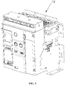
- FIG. 1 shows the air circuit breaker.
- FIG. 2 schematically shows a process in which the current transformer and a relay 20 of the air circuit breaker block the abnormal current.
- the current transformer according to one embodiment of the present disclosure may be included in an air circuit breaker.
- the current applied to the air circuit breaker flows along the main circuit, and the current flowing in the main circuit induces the secondary current through the current transformer according to the present disclosure.
- the induced secondary current is fed to the relay 20 to activate the relay 20.
- the relay 20 When the abnormal current such as overcurrent, short circuit and ground fault occurs in the main circuit of the air circuit breaker, the relay 20 immediately cuts off the current of the air circuit breaker, and the secondary current induced through the current transformer 100 according to the present disclosure may be used as the current to activate the relay 20.
- the current transformer 100 includes a power current transformer (Power CT) and a signal current transformer (Signal CT).
- Power CT power current transformer
- Synignal CT signal current transformer
- the power current transformer is composed of a magnet to induce the secondary current.
- the secondary current derived from the power current transformer is supplied to the relay 20.
- a signal current transformer composed of a Rogowski coil delivers a signal magnitude of the current to the relay 20.
- the relay 20 operates using the current supplied from the power current transformer, and controls the air circuit breaker according to the signal magnitude of the current input through the signal current transformer.
- FIG. 3 is a perspective view and a side view of the current transformer according to one embodiment of the present disclosure.
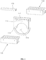
- FIG. 4 is an exploded perspective view of the current transformer according to one embodiment of the present disclosure.
- FIG. 5 is a perspective view of a magnetic core in the current transformer according to one embodiment of the present disclosure.
- the current transformer 100 includes a magnetic core 110, a secondary coil 120 and a magnetic flux compensation member 130.
- the main circuit of the air circuit breaker 10 passes through the magnetic core 110. Further, the secondary coil 120 is disposed adjacent to the magnetic core 110, and the secondary current is induced in the secondary coil 120 due to the current flowing through the main circuit.
- the magnetic flux compensation member 130 is coupled to the magnetic core 110. Further, the magnetic flux compensation member 130 may compensate for the current induced in the secondary coil 120.
- the magnetic core 110 is made of a magnetic material.
- the magnetic core 110 may be embodied as a plate-like member having a predetermined thickness, and may have a through-hole 116 defined therein through which the main circuit of the air circuit breaker passes.
- the through-hole 116 may be sized such that an inner face thereof is not in contact with the main circuit.
- the main circuit passes through a center region of the through-hole 116 in a perpendicular direction to a virtual plane formed by the through-hole 116. Further, the through-hole 116 may have a circular shape.
- the magnetic core 110 includes a first shunt 112 and a second shunt 114 in which the magnetic flux is induced from the main circuit passing through the through-hole 116.
- the magnetic core 110 is divided so that the magnet constituting the magnetic core 110 has at least two paths at one side of the through-hole 116 through which the main circuit passes.
- the first shunt 112 is a path relatively far from the through-hole 116
- the second shunt 114 is a path relatively closer to the through-hole 116.
- first shunt 112 and the second shunt 114 may divide the magnetic flux induced through the main circuit into a first flux a and a second flux b, respectively.
- a section of the magnetic core 110 in which the magnet has one path around the through-hole 116 through the main circuit passes is represented as c in the drawing in which a single magnetic flux is generated.
- the secondary coil 120 is coupled to the magnetic core 110 and extends in an elongate manner along a longitudinal direction of the first shunt 112.
- the number of windings of the secondary coil 120 may be determined according to an embodiment to which the present disclosure is applied.
- the secondary current induced from the current flowing through the main circuit flows through the secondary coil 120, and the secondary current is affected by the magnetic flux induced in the first shunt 112.
- the secondary current induced in the secondary coil 120 has a magnitude that is proportional to a magnitude of the magnetic flux generated in the first shunt 112.
- the secondary current flowing through the secondary coil 120 is supplied to the relay 20 as described above, and thus the relay 20 is activated using the secondary current.
- the current applied to the main circuit of the air circuit breaker is not always maintained in a constant region.
- the magnitude of the secondary current induced in the secondary coil 120 may increase. As the magnitude of the secondary current increases, overheating or ignition due to overheating may occur.
- the magnetic flux compensation member 130 may act as a conductor coupled to the second shunt 114 and may compensate for the magnetic flux generated in the first shunt 112 so that a stable secondary current is finally supplied to the relay.
- the magnetic flux compensation member 130 may be embodied as a plate-shaped member having a predetermined thickness. In one embodiment of the present disclosure, the magnetic flux compensation member 130 may be implemented as a rectangular plate member.
- the magnetic flux compensation member 130 is coupled to the magnetic core 110 and may be embodied as a stack of a plurality of thin plate-like members spaced from each other.
- the magnetic flux compensation member 130 may be coupled to the second shunt 114 of the magnetic core 110.
- the magnetic flux compensation member 130 may include many opposing plates sandwiching the magnetic core 110 therebetween.
- the magnetic flux compensation member 130 acts to reduce the magnetic flux of the first shunt 112 when the current flowing in the main circuit belongs to the rated current region.
- the magnitude of the magnetic flux is obtained as a product of an intensity of the magnetic field and an area through which the magnetic field passes.
- the second shunt 114 to which the magnetic flux compensation member 130 is coupled has a relatively larger cross-sectional area than that of the magnet of the first shunt 112. Therefore, under the same condition, the magnetic flux induced from the second shunt 114 having a wider cross-sectional area is greater than that from the first shunt 112.
- the magnitude of the magnetic flux induced from the first shunt 112 is relatively small.
- the reduced magnetic flux from the first shunt 112 reduces the magnitude of the current induced in the secondary coil 120. Accordingly, the current transformer 100 according to the present disclosure is not exposed to overheating or fire hazard.
- the magnetic flux compensation member 130 is not disposed only on a partial section of the second shunt 114, but face-contacts the magnetic core 110 in the entire section of the second shunt 114.
- FIG. 6 is a perspective view showing a coupling position and a size of the magnetic flux compensation member in the current transformer according to one embodiment of the present disclosure.
- the magnetic flux compensation member 130 is in face-contact with the magnetic core 110 along the distance h at which the virtual straight line 1 and the magnetic core 110 overlap each other.
- This limitation is intended to place the magnetic flux compensation member 130 in the widest area between the main circuit and the secondary coil 120 within a size of the magnetic core 110.
- the magnetic flux compensation member 130 may be formed to have a length of w corresponding to a length of the secondary coil 120.
- the magnetic flux compensation member 130 When the magnetic flux compensation member 130 is disposed on the magnetic core 110 and on a larger area thereof, the number of plate-like members of the magnetic flux compensation member 130 overlapping each other may be reduced, which prevents the magnetic flux compensation member 130 from protruding significantly from the magnetic core 110.
- h is defined as a vertical dimension of the magnetic flux compensation member 130
- a width w is defined as the width of the magnetic flux compensation member 130.
- a dimension in a direction in which the current flows in the main circuit is defined as a thickness of the magnetic flux compensation member 130.
- the magnetic flux compensation member 130 is implemented as a plate-shaped member having a predetermined thickness and the vertical dimension h along which the shortest virtual connection line 1 connecting between the main circuit and the secondary coil overlaps the magnetic core 110.
- FIG. 7 is a perspective view showing a state in which the current transformer according to one embodiment of the present disclosure is coupled to a housing.
- the current transformer 100 may be accommodated in a housing 140.
- a mold may be formed on an outer face of the current transformer 100 and protect the current transformer 100.
- the housing 140 or the molding may not completely receive the current transformer 100.
- the magnetic flux compensation member 130 may be vulnerable to vibration due to a large protruding dimension thereof, and may be damaged due to repeated vibration and external force.
- the magnetic flux compensation member 130 of the current transformer 100 may face-contact the magnetic core 110 on a as wide area as possible, thereby to minimize the protruding dimension of the magnetic flux compensation member 130.
- the effect of improving the stability against the vibration may be obtained using the current transformer 100 according to the present disclosure.
Landscapes
- Engineering & Computer Science (AREA)
- Power Engineering (AREA)
- Physics & Mathematics (AREA)
- General Physics & Mathematics (AREA)
- Chemical & Material Sciences (AREA)
- Composite Materials (AREA)
- Transformers For Measuring Instruments (AREA)
- Driving Mechanisms And Operating Circuits Of Arc-Extinguishing High-Tension Switches (AREA)
Abstract
Description
- The present disclosure relates to a current transformer of an air circuit breaker.
- In general, an air circuit breaker is used in a distribution box in a power plant or a substation.
- When abnormal currents such as overcurrent, short circuit and ground fault occur in the distribution box, the air circuit breaker blocks the currents. A relay is installed in the air circuit breaker to block the current when the abnormal current occurs. The relay operates upon receiving a secondary current generated from a current transformer.
- The current transformer includes a magnetic core through which a main circuit through which AC current flows extends. A primary current is induced in the magnetic core. A secondary coil is placed adjacent to the magnetic core, and a secondary current of a magnitude proportional to that of the current flowing through the main circuit is induced in the secondary coil, and the secondary current induced through the secondary coil is supplied to the relay.
- In this connection, when the current flowing through the main circuit is in a low current region, there is no problem with the magnitude of the current supplied to the relay. When the current flowing through the main circuit flows for a long time in a rated current region, the magnitude of the secondary current increases, thereby causing a problem that the current transformer is heated.
- To solve this problem, a magnetic flux flowing adjacent to the secondary coil is compensated so that the secondary current is induced to have a sufficient magnitude in the low current region, and the magnetic flux of the secondary coil is reduced to stabilize the secondary current in a normal current region.
- Therefore, a method for solving these problems is required.
- The present disclosure is conceived to solve the problems of the prior art. Thus, a purpose of the present disclosure is to stably supply the secondary current induced through the current transformer to the relay. Further, a purpose of the present disclosure is to provide a current transformer with a small volume while reducing a risk of fire by reducing the heat generation of the magnetic core.
- The purposes of the present disclosure are not limited to the purposes mentioned above, and other purposes that are not mentioned will be clearly understood by those skilled in the art from the following description.
- The current transformer according to the present disclosure to achieve the above purpose may include a magnetic core, a secondary coil and a magnetic flux compensation member. The main circuit of the air circuit breaker passes through the magnetic core. Further, the secondary coil is disposed adjacent to the magnetic core and the secondary current is induced through the current flowing through the main circuit. Further, the secondary coil supplies the induced secondary current to the relay. The magnetic flux compensation member is coupled to the magnetic core to compensate for the current induced in the secondary coil.
- In one embodiment of the present disclosure, the magnetic flux compensation member may be coupled to both side faces of the magnetic core.
- In one embodiment of the present disclosure, the magnetic flux compensation member may be embodied as a plate member having a predetermined thickness.
- In one embodiment of the present disclosure, the magnetic flux compensation member may be embodied as a stack of a plurality of plate-shaped members spaced from each other, each having a predetermined thickness, and may be coupled to the magnetic core.
- In one embodiment of the present disclosure, the magnetic core has a through-hole defined therein through which the main circuit passes, wherein the secondary coil is coupled to a first shunt spaced from the magnetic core by a predetermined distance, wherein the magnetic flux compensation member extends vertically by a first distance, wherein a virtual connection line having a shortest distance and connecting the secondary coil and the main circuit to other overlaps the magnetic core by the first distance.
- In one embodiment of the present disclosure, the magnetic flux compensation member includes a plate-shaped member having a predetermined thickness and having a vertical dimension equal to the first distance.
- The current transformer according to the present disclosure to solve the above problems increases the magnetic flux of the secondary coil when the main circuit of the air circuit breaker is in a low current region, and supplies a sufficient magnitude of the secondary current to the relay. When the main circuit is in a normal current region, the current transformer according to the present disclosure may reduce the magnetic flux of the secondary coil, thereby stabilizing the secondary current. Further, when the main circuit is in a normal current region, the secondary current is stabilized, such that the heat generation is reduced, thereby reducing the risk of the fire.
- Further, since the magnetic core has a relatively small volume, the utilization of space is increased, and the risk of noise or damage due to vibration is reduced.
- The effects of the present disclosure are not limited to the effects mentioned above, and other effects not mentioned will be clearly understood by those skilled in the art from the description of the claims.
-
-
FIG. 1 shows an air circuit breaker. -
FIG. 2 schematically shows a process in which a current transformer and a relay of the air circuit breaker block an abnormal current. -
FIG. 3 is a perspective view and a side view of a current transformer according to one embodiment of the present disclosure. -
FIG. 4 is an exploded perspective view of a current transformer according to one embodiment of the present disclosure. -
FIG. 5 is a perspective view of a magnetic core in a current transformer according to one embodiment of the present disclosure. -
FIG. 6 is a perspective view showing a coupling position and a size of a magnetic flux compensation member in a current transformer according to one embodiment of the present disclosure. -
FIG. 7 is a perspective view showing a state in which a current transformer according to one embodiment of the present disclosure is coupled to a housing. - The above-described objects, features, and advantages will be described later in detail with reference to the accompanying drawings, and accordingly, a person having ordinary knowledge in the technical field to which the present disclosure belongs may easily implement the technical idea of the present disclosure. In describing the present disclosure, when it is determined that a detailed description of a known component related to the present disclosure may unnecessarily obscure gist of the present disclosure, the detailed description is omitted.
- Hereinafter, exemplary embodiments according to the present disclosure will be illustrated in detail with reference to the accompanying drawings. In the drawings, the same reference numerals indicate the same or similar elements.
- Hereinafter, a current transformer according to some embodiments of the present disclosure will be described.
-
FIG. 1 shows the air circuit breaker.FIG. 2 schematically shows a process in which the current transformer and arelay 20 of the air circuit breaker block the abnormal current. - The current transformer according to one embodiment of the present disclosure may be included in an air circuit breaker.
- As shown in
FIG. 2 , the current applied to the air circuit breaker flows along the main circuit, and the current flowing in the main circuit induces the secondary current through the current transformer according to the present disclosure. The induced secondary current is fed to therelay 20 to activate therelay 20. - When the abnormal current such as overcurrent, short circuit and ground fault occurs in the main circuit of the air circuit breaker, the
relay 20 immediately cuts off the current of the air circuit breaker, and the secondary current induced through thecurrent transformer 100 according to the present disclosure may be used as the current to activate therelay 20. - As shown in
FIG. 2 , thecurrent transformer 100 according to the present disclosure includes a power current transformer (Power CT) and a signal current transformer (Signal CT). - The power current transformer is composed of a magnet to induce the secondary current. The secondary current derived from the power current transformer is supplied to the
relay 20. - Further, a signal current transformer composed of a Rogowski coil delivers a signal magnitude of the current to the
relay 20. - The
relay 20 operates using the current supplied from the power current transformer, and controls the air circuit breaker according to the signal magnitude of the current input through the signal current transformer. -
FIG. 3 is a perspective view and a side view of the current transformer according to one embodiment of the present disclosure.FIG. 4 is an exploded perspective view of the current transformer according to one embodiment of the present disclosure.FIG. 5 is a perspective view of a magnetic core in the current transformer according to one embodiment of the present disclosure. - As shown in
FIG. 3 andFIG. 4 , thecurrent transformer 100 according to one embodiment of the present disclosure includes amagnetic core 110, asecondary coil 120 and a magneticflux compensation member 130. - The main circuit of the
air circuit breaker 10 passes through themagnetic core 110. Further, thesecondary coil 120 is disposed adjacent to themagnetic core 110, and the secondary current is induced in thesecondary coil 120 due to the current flowing through the main circuit. - The magnetic
flux compensation member 130 is coupled to themagnetic core 110. Further, the magneticflux compensation member 130 may compensate for the current induced in thesecondary coil 120. - Each of the above-described components will be described in more detail below.
- The
magnetic core 110 is made of a magnetic material. In one embodiment of the present disclosure, themagnetic core 110 may be embodied as a plate-like member having a predetermined thickness, and may have a through-hole 116 defined therein through which the main circuit of the air circuit breaker passes. - The through-
hole 116 may be sized such that an inner face thereof is not in contact with the main circuit. The main circuit passes through a center region of the through-hole 116 in a perpendicular direction to a virtual plane formed by the through-hole 116. Further, the through-hole 116 may have a circular shape. - The
magnetic core 110 includes afirst shunt 112 and asecond shunt 114 in which the magnetic flux is induced from the main circuit passing through the through-hole 116. - When the current is applied to the main circuit, the magnetic flux is induced in the magnet around the main circuit. Therefore, the
magnetic core 110 is divided so that the magnet constituting themagnetic core 110 has at least two paths at one side of the through-hole 116 through which the main circuit passes. - In this connection, among the two paths, the
first shunt 112 is a path relatively far from the through-hole 116, and thesecond shunt 114 is a path relatively closer to the through-hole 116. - As shown in
FIG. 5 , when the current is applied to the main circuit, a magnetic field is generated along a circumference of the main circuit. The magnetic field generated around the main circuit generates a magnetic flux in one direction along themagnetic core 110. - In this connection, the
first shunt 112 and thesecond shunt 114 may divide the magnetic flux induced through the main circuit into a first flux a and a second flux b, respectively. A section of themagnetic core 110 in which the magnet has one path around the through-hole 116 through the main circuit passes is represented as c in the drawing in which a single magnetic flux is generated. - The
secondary coil 120 is coupled to themagnetic core 110 and extends in an elongate manner along a longitudinal direction of thefirst shunt 112. The number of windings of thesecondary coil 120 may be determined according to an embodiment to which the present disclosure is applied. - Accordingly, the secondary current induced from the current flowing through the main circuit flows through the
secondary coil 120, and the secondary current is affected by the magnetic flux induced in thefirst shunt 112. Specifically, the secondary current induced in thesecondary coil 120 has a magnitude that is proportional to a magnitude of the magnetic flux generated in thefirst shunt 112. - The secondary current flowing through the
secondary coil 120 is supplied to therelay 20 as described above, and thus therelay 20 is activated using the secondary current. - The current applied to the main circuit of the air circuit breaker is not always maintained in a constant region.
- Current in a low current region or a rated current region (high current region) may flow along the main circuit.
- In particular, when the current in the rated current region flows along the main circuit, the magnitude of the secondary current induced in the
secondary coil 120 may increase. As the magnitude of the secondary current increases, overheating or ignition due to overheating may occur. - The magnetic
flux compensation member 130 may act as a conductor coupled to thesecond shunt 114 and may compensate for the magnetic flux generated in thefirst shunt 112 so that a stable secondary current is finally supplied to the relay. - The magnetic
flux compensation member 130 may be embodied as a plate-shaped member having a predetermined thickness. In one embodiment of the present disclosure, the magneticflux compensation member 130 may be implemented as a rectangular plate member. - As shown in
FIG. 4 , the magneticflux compensation member 130 is coupled to themagnetic core 110 and may be embodied as a stack of a plurality of thin plate-like members spaced from each other. - In this connection, the magnetic
flux compensation member 130 may be coupled to thesecond shunt 114 of themagnetic core 110. The magneticflux compensation member 130 may include many opposing plates sandwiching themagnetic core 110 therebetween. - The magnetic
flux compensation member 130 acts to reduce the magnetic flux of thefirst shunt 112 when the current flowing in the main circuit belongs to the rated current region. - Specifically, the magnitude of the magnetic flux is obtained as a product of an intensity of the magnetic field and an area through which the magnetic field passes. Accordingly, the
second shunt 114 to which the magneticflux compensation member 130 is coupled has a relatively larger cross-sectional area than that of the magnet of thefirst shunt 112. Therefore, under the same condition, the magnetic flux induced from thesecond shunt 114 having a wider cross-sectional area is greater than that from thefirst shunt 112. The magnitude of the magnetic flux induced from thefirst shunt 112 is relatively small. - The reduced magnetic flux from the
first shunt 112 reduces the magnitude of the current induced in thesecondary coil 120. Accordingly, thecurrent transformer 100 according to the present disclosure is not exposed to overheating or fire hazard. - The magnetic
flux compensation member 130 is not disposed only on a partial section of thesecond shunt 114, but face-contacts themagnetic core 110 in the entire section of thesecond shunt 114. -
FIG. 6 is a perspective view showing a coupling position and a size of the magnetic flux compensation member in the current transformer according to one embodiment of the present disclosure. - As shown in
FIG. 6 , assuming that a shortest virtual straight line connecting the main circuit and the secondary coil is denoted as 1, a distance at which the virtual straight line 1 and themagnetic core 110 overlap each other is h. Therefore, the magneticflux compensation member 130 is in face-contact with themagnetic core 110 along the distance h at which the virtual straight line 1 and themagnetic core 110 overlap each other. - This limitation is intended to place the magnetic
flux compensation member 130 in the widest area between the main circuit and thesecondary coil 120 within a size of themagnetic core 110. - Further, the magnetic
flux compensation member 130 may be formed to have a length of w corresponding to a length of thesecondary coil 120. - When the magnetic
flux compensation member 130 is disposed on themagnetic core 110 and on a larger area thereof, the number of plate-like members of the magneticflux compensation member 130 overlapping each other may be reduced, which prevents the magneticflux compensation member 130 from protruding significantly from themagnetic core 110. - Further, in one embodiment of the present disclosure, h is defined as a vertical dimension of the magnetic
flux compensation member 130, and a width w is defined as the width of the magneticflux compensation member 130. Further, in a state in which the magneticflux compensation member 130 is coupled to themagnetic core 110, a dimension in a direction in which the current flows in the main circuit is defined as a thickness of the magneticflux compensation member 130. - Accordingly, the magnetic
flux compensation member 130 is implemented as a plate-shaped member having a predetermined thickness and the vertical dimension h along which the shortest virtual connection line 1 connecting between the main circuit and the secondary coil overlaps themagnetic core 110. -
FIG. 7 is a perspective view showing a state in which the current transformer according to one embodiment of the present disclosure is coupled to a housing. - As shown in
FIG. 7 , thecurrent transformer 100 according to the present disclosure may be accommodated in ahousing 140. Alternatively, a mold may be formed on an outer face of thecurrent transformer 100 and protect thecurrent transformer 100. - In this connection, when the magnetic
flux compensation member 130 protrudes significantly from themagnetic core 110, thehousing 140 or the molding may not completely receive thecurrent transformer 100. - Further, the magnetic
flux compensation member 130 may be vulnerable to vibration due to a large protruding dimension thereof, and may be damaged due to repeated vibration and external force. - Due to the characteristics that the magnetic flux changes according to the cross-sectional area, the magnetic
flux compensation member 130 of thecurrent transformer 100 according to the present disclosure may face-contact themagnetic core 110 on a as wide area as possible, thereby to minimize the protruding dimension of the magneticflux compensation member 130. - Therefore, the effect of improving the stability against the vibration may be obtained using the
current transformer 100 according to the present disclosure. - As described above, preferred embodiments according to the present disclosure have been described. A fact that the present disclosure may be embodied in other specific forms without departing from a purpose or scope thereof in addition to the above-described embodiments is obvious to the skilled person to the art. Therefore, the above-described embodiments should be regarded as illustrative rather than restrictive, and accordingly, the present disclosure is not limited to the above description and may be changed within the scope of the appended claims and equivalents thereof.
Claims (6)
- A current transformer (100) comprising:a magnetic core (110) through which a main circuit of an air circuit breaker (10) passes;a secondary coil (120) disposed adjacent to the magnetic core (110) to induce a secondary current from a current flowing through the main circuit and to supply the secondary current to a relay (20); anda magnetic flux compensation member (130) coupled to the magnetic core (110) to compensate for the current induced from the secondary coil (120).
- The current transformer of claim 1, wherein the magnetic flux compensation member (130) is coupled to both side faces of the magnetic core (110).
- The current transformer of claim 1, wherein the magnetic flux compensation member (130) is a plate-like member having a predetermined thickness.
- The current transformer of claim 3, wherein the magnetic flux compensation member (130) includes a plurality of plate-like members having a predetermined thickness and coupled to the magnetic core (110) and overlapping each other.
- The current transformer of claim 1, wherein the magnetic core (110) has a through-hole (116) defined therein through which the main circuit passes,wherein the secondary coil (120) is coupled to a first shunt (112) spaced from the magnetic core (110) by a predetermined distance,wherein the magnetic flux compensation member (130) extends vertically by a first distance, wherein a virtual connection line having a shortest distance and connecting the secondary coil (120) and the main circuit to other overlaps the magnetic core (110) by the first distance.
- The current transformer of claim 5, wherein the magnetic flux compensation member (130) includes a plate-shaped member having a predetermined thickness and having a vertical dimension equal to the first distance.
Applications Claiming Priority (2)
| Application Number | Priority Date | Filing Date | Title |
|---|---|---|---|
| KR1020180169803A KR102153970B1 (en) | 2018-12-26 | 2018-12-26 | Current transformer for air circuit breaker |
| PCT/KR2019/012042 WO2020138654A1 (en) | 2018-12-26 | 2019-09-18 | Current transformer of air circuit breaker |
Publications (2)
| Publication Number | Publication Date |
|---|---|
| EP3905287A1 true EP3905287A1 (en) | 2021-11-03 |
| EP3905287A4 EP3905287A4 (en) | 2022-03-09 |
Family
ID=71126515
Family Applications (1)
| Application Number | Title | Priority Date | Filing Date |
|---|---|---|---|
| EP19902184.1A Pending EP3905287A4 (en) | 2018-12-26 | 2019-09-18 | CURRENT TRANSFORMER FOR AN AIR CIRCUIT BREAKER |
Country Status (6)
| Country | Link |
|---|---|
| US (1) | US11810709B2 (en) |
| EP (1) | EP3905287A4 (en) |
| JP (1) | JP7196306B2 (en) |
| KR (1) | KR102153970B1 (en) |
| CN (1) | CN112997264B (en) |
| WO (1) | WO2020138654A1 (en) |
Families Citing this family (5)
| Publication number | Priority date | Publication date | Assignee | Title |
|---|---|---|---|---|
| JP1675483S (en) * | 2020-04-27 | 2020-12-21 | ||
| EP4309197A2 (en) * | 2021-03-19 | 2024-01-24 | Redur Gmbh & Co. KG | Low voltage shielding element, low voltage current transformer, low voltage current transformer arrangement and low voltage electrical arrangement |
| USD1042359S1 (en) * | 2022-01-18 | 2024-09-17 | Eaton Intelligent Power Limited | Circuit interrupter cover |
| USD1070790S1 (en) * | 2022-05-13 | 2025-04-15 | Schneider Electric Industries Sas | Command and control panel of electric circuit breaker |
| KR102898521B1 (en) * | 2024-08-21 | 2025-12-10 | 에이치디현대일렉트릭 주식회사 | Enclosure for air breaker current sensor, air breaker current sensor and air breaker current sensor system |
Family Cites Families (24)
| Publication number | Priority date | Publication date | Assignee | Title |
|---|---|---|---|---|
| JPS622747Y2 (en) * | 1981-03-09 | 1987-01-22 | ||
| US4876625A (en) * | 1988-11-04 | 1989-10-24 | Westinghouse Electric Corp. | Composite circuit breaker system |
| FR2725320B1 (en) * | 1994-09-29 | 1996-10-31 | Schneider Electric Sa | TRIGGERING DEVICE HAVING AT LEAST ONE CURRENT TRANSFORMER |
| JP2001264364A (en) * | 2000-03-14 | 2001-09-26 | Matsushita Electric Ind Co Ltd | Optical current transformer |
| JP2002064019A (en) * | 2000-08-22 | 2002-02-28 | Sony Corp | Magnetic core and coil device provided with this magnetic core |
| ITBG20030062A1 (en) * | 2003-12-30 | 2005-06-30 | Abb Service Srl | POWER SUPPLY FOR AN ELECTRONIC PROTECTION DEVICE TO BE USED IN A LOW VOLTAGE SWITCH. |
| US7561387B2 (en) * | 2005-10-19 | 2009-07-14 | Eaton Corporation | Current transformer including a low permeability shunt and a trip device employing the same |
| KR100657645B1 (en) * | 2006-01-04 | 2006-12-14 | 부전전자부품 주식회사 | A transformer having auxiliary core |
| AU2013273724A1 (en) * | 2006-06-14 | 2014-01-16 | Sines, Eddie MR | Method and apparatus for direct energy conversion |
| DE102008049432B4 (en) | 2008-09-25 | 2018-02-08 | Siemens Aktiengesellschaft | Circuit breaker and current transformer for a circuit breaker |
| CN101908413B (en) * | 2010-07-27 | 2012-10-03 | 上海诺雅克电气有限公司 | Current transformer for supplying power for electronic device |
| US9224531B2 (en) * | 2011-03-31 | 2015-12-29 | Bose Corporation | Power converter using orthogonal secondary windings |
| CN102800471A (en) * | 2011-05-26 | 2012-11-28 | 北京人民电器厂有限公司 | Quick saturation current transformer |
| JP5948958B2 (en) * | 2012-02-29 | 2016-07-06 | 富士電機機器制御株式会社 | Current detector |
| JP5850248B2 (en) * | 2012-04-20 | 2016-02-03 | 株式会社デンソー | Non-contact power feeding device |
| FR2990759B1 (en) | 2012-05-21 | 2014-05-02 | Schneider Electric Ind Sas | MIXED CURRENT SENSOR AND METHOD OF MOUNTING SAME |
| US9472329B2 (en) * | 2012-08-15 | 2016-10-18 | Bruce W. Carsten | High leakage transformers with tape wound cores |
| WO2014141901A1 (en) * | 2013-03-13 | 2014-09-18 | 三菱電機株式会社 | Solenoid-operated device |
| US9607749B2 (en) * | 2014-01-23 | 2017-03-28 | Veris Industries, Llc | Split core current transformer |
| US10043627B2 (en) * | 2014-02-06 | 2018-08-07 | Abb S.P.A. | Device for monitoring a current of a primary conductor with respect to a predetermined current threshold, and related trip assembly and switching device |
| CN105336484B (en) | 2014-08-06 | 2018-05-01 | 上海电科电器科技有限公司 | Current transformer |
| KR102539688B1 (en) | 2016-04-28 | 2023-06-07 | 엘에스일렉트릭(주) | Leakage Current Detector |
| JP2018112535A (en) * | 2017-01-13 | 2018-07-19 | パナソニックIpマネジメント株式会社 | Current measurement system and panelboard |
| FR3089340B1 (en) | 2018-11-29 | 2020-10-30 | Schneider Electric Ind Sas | Current transformer, protection device and electrical circuit breaker comprising such a transformer |
-
2018
- 2018-12-26 KR KR1020180169803A patent/KR102153970B1/en active Active
-
2019
- 2019-09-18 EP EP19902184.1A patent/EP3905287A4/en active Pending
- 2019-09-18 US US17/414,002 patent/US11810709B2/en active Active
- 2019-09-18 WO PCT/KR2019/012042 patent/WO2020138654A1/en not_active Ceased
- 2019-09-18 CN CN201980074144.2A patent/CN112997264B/en active Active
- 2019-09-18 JP JP2021531847A patent/JP7196306B2/en active Active
Also Published As
| Publication number | Publication date |
|---|---|
| KR102153970B1 (en) | 2020-09-09 |
| JP7196306B2 (en) | 2022-12-26 |
| WO2020138654A1 (en) | 2020-07-02 |
| KR20200080007A (en) | 2020-07-06 |
| CN112997264A (en) | 2021-06-18 |
| US11810709B2 (en) | 2023-11-07 |
| EP3905287A4 (en) | 2022-03-09 |
| CN112997264B (en) | 2024-08-06 |
| US20220044869A1 (en) | 2022-02-10 |
| JP2022515034A (en) | 2022-02-17 |
Similar Documents
| Publication | Publication Date | Title |
|---|---|---|
| US11810709B2 (en) | Current transformer of air circuit breaker | |
| KR102086355B1 (en) | Linear electromagnetic device | |
| US8994487B2 (en) | Transformer | |
| US11133142B2 (en) | Power switch | |
| EP2779180B1 (en) | Transformer | |
| US20130285786A1 (en) | Current transformer for supplying power to electronic controller | |
| RU2390865C2 (en) | Current transformer for electric power supply and manufacturing method thereof | |
| JP6490355B2 (en) | Reactor parts and reactors | |
| CN104395975A (en) | Current transformer assembly | |
| US20040178877A1 (en) | Silicon steel core for transformers or choke coils | |
| US10403432B2 (en) | Power transfer unit of a system for inductive power transfer, a method of manufacturing a primary power transfer unit and of operating a primary power transfer unit | |
| JP2015038986A (en) | Transformer core flux control for power management | |
| JP2006245050A (en) | Coil parts and reactors | |
| KR20130120220A (en) | Current transformer for air circuit breaker | |
| KR101447054B1 (en) | Terminal plate for transformer | |
| US1467771A (en) | Current-limiting reactance coil | |
| TW202109568A (en) | Current transformer module | |
| KR200203543Y1 (en) | Reactor structure with air gap on magnetic pass | |
| KR100815467B1 (en) | Pass-core with laminated insulation of transformer | |
| KR101031589B1 (en) | Transformers | |
| KR102094777B1 (en) | Transformer | |
| JP2017212324A (en) | Current limiting coil for DC power supply | |
| JP2019096725A (en) | High frequency transformer and high frequency coil | |
| EP3751588A1 (en) | Electric transformer | |
| BR102014030213A2 (en) | Magnetic flux bypass bridge oriented grain-bladed core current transformer used in interrupt device |
Legal Events
| Date | Code | Title | Description |
|---|---|---|---|
| STAA | Information on the status of an ep patent application or granted ep patent |
Free format text: STATUS: THE INTERNATIONAL PUBLICATION HAS BEEN MADE |
|
| PUAI | Public reference made under article 153(3) epc to a published international application that has entered the european phase |
Free format text: ORIGINAL CODE: 0009012 |
|
| STAA | Information on the status of an ep patent application or granted ep patent |
Free format text: STATUS: REQUEST FOR EXAMINATION WAS MADE |
|
| 17P | Request for examination filed |
Effective date: 20210722 |
|
| AK | Designated contracting states |
Kind code of ref document: A1 Designated state(s): AL AT BE BG CH CY CZ DE DK EE ES FI FR GB GR HR HU IE IS IT LI LT LU LV MC MK MT NL NO PL PT RO RS SE SI SK SM TR |
|
| REG | Reference to a national code |
Ref country code: DE Ref legal event code: R079 Free format text: PREVIOUS MAIN CLASS: H01F0027420000 Ipc: H01F0038300000 |
|
| A4 | Supplementary search report drawn up and despatched |
Effective date: 20220208 |
|
| RIC1 | Information provided on ipc code assigned before grant |
Ipc: H01H 71/12 20060101ALI20220202BHEP Ipc: H01F 3/12 20060101ALI20220202BHEP Ipc: H01F 38/30 20060101AFI20220202BHEP |
|
| DAV | Request for validation of the european patent (deleted) | ||
| DAX | Request for extension of the european patent (deleted) | ||
| STAA | Information on the status of an ep patent application or granted ep patent |
Free format text: STATUS: EXAMINATION IS IN PROGRESS |
|
| 17Q | First examination report despatched |
Effective date: 20241031 |