EP3905264A1 - Method for decommissioning nuclear facility - Google Patents
Method for decommissioning nuclear facility Download PDFInfo
- Publication number
- EP3905264A1 EP3905264A1 EP19902864.8A EP19902864A EP3905264A1 EP 3905264 A1 EP3905264 A1 EP 3905264A1 EP 19902864 A EP19902864 A EP 19902864A EP 3905264 A1 EP3905264 A1 EP 3905264A1
- Authority
- EP
- European Patent Office
- Prior art keywords
- pressure vessel
- reactor pressure
- nuclear reactor
- nuclear
- bio
- Prior art date
- Legal status (The legal status is an assumption and is not a legal conclusion. Google has not performed a legal analysis and makes no representation as to the accuracy of the status listed.)
- Pending
Links
Images




Classifications
-
- G—PHYSICS
- G21—NUCLEAR PHYSICS; NUCLEAR ENGINEERING
- G21D—NUCLEAR POWER PLANT
- G21D1/00—Details of nuclear power plant
- G21D1/003—Nuclear facilities decommissioning arrangements
-
- G—PHYSICS
- G21—NUCLEAR PHYSICS; NUCLEAR ENGINEERING
- G21C—NUCLEAR REACTORS
- G21C1/00—Reactor types
- G21C1/04—Thermal reactors ; Epithermal reactors
- G21C1/06—Heterogeneous reactors, i.e. in which fuel and moderator are separated
- G21C1/08—Heterogeneous reactors, i.e. in which fuel and moderator are separated moderator being highly pressurised, e.g. boiling water reactor, integral super-heat reactor, pressurised water reactor
- G21C1/086—Pressurised water reactors
-
- Y—GENERAL TAGGING OF NEW TECHNOLOGICAL DEVELOPMENTS; GENERAL TAGGING OF CROSS-SECTIONAL TECHNOLOGIES SPANNING OVER SEVERAL SECTIONS OF THE IPC; TECHNICAL SUBJECTS COVERED BY FORMER USPC CROSS-REFERENCE ART COLLECTIONS [XRACs] AND DIGESTS
- Y02—TECHNOLOGIES OR APPLICATIONS FOR MITIGATION OR ADAPTATION AGAINST CLIMATE CHANGE
- Y02E—REDUCTION OF GREENHOUSE GAS [GHG] EMISSIONS, RELATED TO ENERGY GENERATION, TRANSMISSION OR DISTRIBUTION
- Y02E30/00—Energy generation of nuclear origin
- Y02E30/30—Nuclear fission reactors
Definitions
- the present disclosure relates to a method for decommissioning a nuclear facility.
- a pressurized water reactor type of nuclear power plant includes a nuclear reactor pressure vessel and bio-protective concrete for surrounding the nuclear reactor pressure vessel.
- the mounting device may include a mounting portion corresponding to a lower portion of the nuclear reactor pressure vessel.
- the mounting portion may include a curved surface.
- the mounting portion may include a step-like surface.
- the mounting device may further include a through-hole penetrating a center of the mounting portion.
- the mounting device may further include an elastic coating layer coated on a surface of the mounting portion.
- the nuclear facility may further include a plurality of pipes directly connected to the nuclear reactor pressure vessel, and the method may further include: expanding an inner wall of the bio-protective concrete forming the cavity; and separating the plurality of pipes from the nuclear reactor pressure vessel.
- the nuclear facility may further include a crane positioned on the bio-protective concrete, and the floating of the nuclear reactor pressure vessel above the cavity may be performed by lifting the nuclear reactor pressure vessel from the bio-protective concrete by using the crane.
- a method for decommissioning a nuclear facility that easily cuts and decommissions a nuclear reactor pressure vessel separated from a bio-protective concrete, is provided.
- a pressurized water reactor (PWR) type of nuclear power plant will be exemplified as the nuclear facility, and without being limited to this, the nuclear facility may be a boiling water reactor (BWR) type of nuclear power plant.
- PWR pressurized water reactor
- BWR boiling water reactor
- the pressurized water reactor type of nuclear power plant uses light-water as a coolant and moderator, and uranium 235 is concentrated to about 2 % to 4 % to be used as nuclear fuel.
- a pressurized light-water reactor type of nuclear power plant is divided into a facility related to a nuclear reactor system that transmits heat generated by nuclear fission within a reactor to a steam generator for heat exchange; and a facility related to a turbine and generator system that turns a turbine with steam generated from the steam generator, returns it to water through a condenser, and then circulates it back to the steam generator.
- a coolant which is a heat transfer medium of a nuclear reactor system
- Equipment configuring the system includes a pressurizer that adjusts pressure to maintain constant enthalpy, and a coolant pump that circulates the coolant between the reactor and the steam generator.
- a system in which the steam generated from the steam generator rotates the turbine to generate power from a generator connected to a turbine shaft may be the same as that of a general thermal power plant.
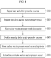
- FIG. 1 illustrates a flowchart of a method for decommissioning a nuclear facility according to an embodiment.
- FIG. 2 to FIG. 10 are drawings for explaining a method for decommissioning a nuclear facility according to an embodiment.
- an inner wall 301 of a bio-protective concrete 300 is expanded (S100).
- FIG. 2 is a drawing of a part of a nuclear facility.
- the nuclear reactor pressure vessel 100 may be a pressurized water reactor type, but is not limited thereto.
- the nuclear reactor pressure vessel 100 may be a boiling water reactor type.
- a protrusion 110 supporting various known types of cores protrudes from an inner wall of the nuclear reactor pressure vessel 100.
- the plurality of pipes 200 are connected to various types of known steam generators. Hot water may pass through one of the pipes 200, and cold water may pass through the other pipe thereof, but the present invention is not limited thereto.
- the bio-protective concrete 300 includes a cavity 310 in which the nuclear reactor pressure vessel 100 is positioned, and the inner wall 301 forming the cavity 310 and facing the nuclear reactor pressure vessel 100.
- the crane 400 is positioned above the bio-protective concrete 300.
- the crane 400 may be a crane 400 used during an initial installation of the nuclear facility, but is not limited thereto.
- FIG. 3 illustrates a state in which the inner wall of the bio-protective concrete is expanded and the pipes are separated from the nuclear reactor pressure vessel in the nuclear facility shown in FIG. 2 .
- the inner wall 301 of the bio-protective concrete slab 300 forming the cavity 310 is cut and expanded by using a cutting member such as a wire saw or a circular saw.
- a portion of the inner wall 301 corresponding to the nuclear reactor pressure vessel 100 is expanded, but the present invention is not limited thereto, and a portion of the inner wall 301 corresponding to an upper portion of the pipes 200 may be expanded.
- the pipes 200 are exposed in an upper direction.
- insulation surrounding the nuclear reactor pressure vessel 100 may be removed.
- the pipes 200 exposed through the expanded inner wall 301 of the bio- protective concrete 300 are cut in a diameter direction of the pipes 200, and the pipes 200 are separated from the nuclear reactor pressure vessel 100.
- the cutting of the pipes 200 may be performed by using a wire saw, but is not limited thereto, and may be performed by using another cutting member such as a circular saw.
- the pipes 200 may be easily cut through the expanded inner wall 301 by using a cutting member.
- FIG. 4 is a drawing in which the nuclear reactor pressure vessel is floating above the cavity in the nuclear facility shown in FIG. 3 .
- the nuclear reactor pressure vessel 100 is floating above the cavity 310 (S300).
- the nuclear reactor pressure vessel 100 whose pipes are cut through the expanded inner wall 301 of the bio-protective concrete 300, is lifted from the bio-protective concrete 300 by using the crane 400 to be floating above the cavity 310 of the bio-protective concrete slab 300.
- the crane 400 may support the protrusion 110 protruding on the inner wall of the nuclear reactor pressure vessel 100 to lift the nuclear reactor pressure vessel 100 from the bio-protective concrete 300, but is not limited thereto.
- the crane 400 may support an upper portion of the nuclear reactor pressure vessel 100 to lift the nuclear reactor pressure vessel 100 from the bio-protective concrete 300.
- the nuclear reactor pressure vessel 100 may be easily lifted from the bio-protective concrete 300 without interference by the bio-protective concrete 300 and the pipes.
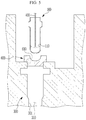
- FIG. 5 is a drawing in which a mounting device is positioned on the cavity of the bio-protective concrete in the nuclear facility shown in FIG. 4 .
- a mounting device 600 is positioned on the bio-protective concrete 300 (S400).
- the mounting device 600 by positioning the mounting device 600 on the bio-protective concrete 300, the cavity 310 is covered with the mounting device 600.
- the mounting device 600 By positioning the mounting device 600 between the cavity 310 of the bio-protective concrete 300 and the floating nuclear reactor pressure vessel 100, the cavity 310 is covered with the mounting device 600.
- the mounting device 600 includes a mounting portion 610 corresponding to a lower portion of the nuclear reactor pressure vessel 100.
- the mounting portion 610 includes a curved surface corresponding to the lower portion of the nuclear reactor pressure vessel 100.
- the curved surface of the mounting portion 610 may have substantially the same curvature as that of the lower portion of the nuclear reactor pressure vessel 100.
- the curvature of the curved surface of the mounting portion 610 may be larger or smaller than that of the lower portion of the nuclear reactor pressure vessel 100.
- FIG. 6 illustrates an example of the mounting device shown in FIG. 5 .
- the mounting device 600 includes the mounting portion 610 and an elastic coating layer 620.
- the elastic coating layer 620 is coated on a surface of the mounting portion 610.
- the elastic coating layer 620 may extend from the surface of the mounting portion 610 to the upper surface of the mounting device 600.
- the elastic coating layer 620 may be coated on the entire surface of the mounting device 600.
- the elastic coating layer 620 may include a polymer.
- the elastic coating layer 620 may include a polymer such as rubber and urethane, but is not limited thereto, and may include various known materials having elasticity.
- FIG. 7 illustrates another example of the mounting device shown in FIG. 5 .
- the mounting device 600 includes the mounting portion 610, the elastic coating layer 620, and a through-hole 630.
- the elastic coating layer 620 is coated on the surface of the mounting portion 610.
- the elastic coating layer 620 may extend from the surface of the mounting portion 610 to the upper surface of the mounting device 600.
- the elastic coating layer 620 may be coated on the entire surface of the mounting device 600.
- the elastic coating layer 620 may include a polymer.
- the elastic coating layer 620 may include a polymer such as rubber and urethane, but is not limited thereto, and may include various known materials having elasticity.
- the through-hole 630 penetrates a center of the mounting portion 610.
- the through-hole 630 communicates with the cavity 310 of the bio-protective concrete 300.
- the through-hole 630 may be circular in a plan view, and thus, the mounting device 600 may have a donut shape in a plan view.
- FIG. 8 illustrates another another example of the mounting device shown in FIG. 5 .
- the mounting device 600 includes the mounting portion 610 corresponding to the lower portion of the nuclear reactor pressure vessel 100.
- the mounting portion 610 includes a step-like surface corresponding to the lower portion of the nuclear reactor pressure vessel 100.
- Corners of steps forming the step-like surface of the mounting portion 610 may be disposed on an imaginary line having substantially the same curvature as the curvature of the lower portion of the nuclear reactor pressure vessel 100.
- FIG. 9 is a drawing in which the nuclear reactor pressure vessel is mounted on the mounting device in the nuclear facility shown in FIG. 5 .
- the nuclear reactor pressure vessel 100 is mounted on the mounting device 600 (S500).
- the lower portion of the nuclear reactor pressure vessel 100 is mounted on the mounting portion 610 of the mounting device 600 that covers the cavity 310 of the bio-protective concrete 300 by using the crane 400.
- the mounting portion 610 of the mounting device 600 contacts the lower portion of the nuclear reactor pressure vessel 100 to support the nuclear reactor pressure vessel 100.
- the nuclear reactor pressure vessel 100 is supported on the cavity 310 of the bio-protective concrete 300 without shaking.
- FIG. 10 is a drawing in which the nuclear reactor pressure vessel mounted on the mounting device in the nuclear facility shown in FIG. 9 is partially cut and decommissioned by using a cutting device.
- the nuclear reactor pressure vessel 100 is cut and decommissioned (S600).
- the nuclear reactor pressure vessel 100 mounted on the mounting device 600 is cut and decommissioned.
- the nuclear reactor pressure vessel 100 supported by the mounting device 600 that covers the cavity 310 of the bio-protective concrete 300 is cut and decommissioned from the upper portion to the lower portion of the reactor pressure vessel 100 by using a cutting device 10 installed on the bio-protective concrete 300, so that the nuclear reactor pressure vessel 100 may be cut and decommissioned.
- the cutting device 10 may include an end effector including a cutting member such as a laser cutter and a grip member such as a gripper.
- the cutting device 10 may allow a pressure vessel piece 101 cut and decommissioned from the nuclear reactor pressure vessel 100 to be stored in a standard size of packaging container 20.
- the packaging container 20 in which the pressure vessel piece 101 is stored may be sealed and taken out of the nuclear facility.
- the cutting and decommissioning of the nuclear reactor pressure vessel 100 using the cutting device 10 may be performed in the state in which the crane 400 is separated from the nuclear reactor pressure vessel 100, but is not limited thereto, and may be performed in a state in which the crane 400 supports the nuclear reactor pressure vessel 100.
- the bio-protective concrete 300 may be cut and decommissioned.
- the bio-protective concrete 300 may be cut and decommissioned by using various known cutting members.
- the nuclear reactor pressure vessel 100 is separated from the cavity 310 of the bio-protective concrete 300 and it is not cut or disassembled after being moved to another place, but the nuclear reactor pressure vessel 100 is mounted on the mounting device 600 covering the cavity 310 of the bio-protective concrete 300 and then it is cut and decommissioned, it is easy to use the space for cutting and decommissioning the nuclear reactor pressure vessel 100. This serves as a factor to reduce a total decommissioning time and decommissioning cost of the nuclear facility.
- the method for dismantling the nuclear facility is provided that easily cuts and decommissions the nuclear reactor pressure vessel 100 separated from the bio-protective concrete 300.
Landscapes
- Physics & Mathematics (AREA)
- Engineering & Computer Science (AREA)
- Plasma & Fusion (AREA)
- General Engineering & Computer Science (AREA)
- High Energy & Nuclear Physics (AREA)
- Working Measures On Existing Buildindgs (AREA)
- Structure Of Emergency Protection For Nuclear Reactors (AREA)
Abstract
Description
- The present disclosure relates to a method for decommissioning a nuclear facility.
- Generally, among nuclear facilities used for nuclear power generation, a pressurized water reactor type of nuclear power plant includes a nuclear reactor pressure vessel and bio-protective concrete for surrounding the nuclear reactor pressure vessel.
- When decommissioning a nuclear facility, it is necessary to separate the nuclear reactor pressure vessel from the bio-protective concrete, and to cut and decommission the nuclear reactor pressure vessel.
- An embodiment is to provide a method for decommissioning a nuclear facility that easily cuts and decommissions a nuclear reactor pressure vessel separated from bio-protective concrete.
- An embodiment provides a method for decommissioning a nuclear facility that includes a nuclear reactor pressure vessel and bio-protective concrete including a cavity in which the nuclear reactor pressure vessel is positioned, including: floating the nuclear reactor pressure vessel above the cavity; positioning a mounting device on the bio-protective concrete to cover the cavity with the mounting device; mounting a lower portion of the nuclear reactor pressure vessel on the mounting device; and cutting and decommissioning the nuclear reactor pressure vessel mounted on the mounting device.
- The mounting device may include a mounting portion corresponding to a lower portion of the nuclear reactor pressure vessel.
- The mounting portion may include a curved surface.
- The mounting portion may include a step-like surface.
- The mounting device may further include a through-hole penetrating a center of the mounting portion.
- The mounting device may further include an elastic coating layer coated on a surface of the mounting portion.
- The nuclear facility may further include a plurality of pipes directly connected to the nuclear reactor pressure vessel, and the method may further include: expanding an inner wall of the bio-protective concrete forming the cavity; and separating the plurality of pipes from the nuclear reactor pressure vessel.
- The nuclear facility may further include a crane positioned on the bio-protective concrete, and the floating of the nuclear reactor pressure vessel above the cavity may be performed by lifting the nuclear reactor pressure vessel from the bio-protective concrete by using the crane.
- According to the embodiment, a method for decommissioning a nuclear facility that easily cuts and decommissions a nuclear reactor pressure vessel separated from a bio-protective concrete, is provided.
-
-
FIG. 1 illustrates a flowchart of a method for decommissioning a nuclear facility according to an embodiment. -
FIG. 2 to FIG. 10 are drawings for explaining a method for decommissioning a nuclear facility according to an embodiment. - The present invention will be described more fully hereinafter with reference to the accompanying drawings, in which embodiments of the invention are shown. As those skilled in the art would realize, the described embodiments may be modified in various different ways, all without departing from the scope of the present invention.
- In addition, unless explicitly described to the contrary, the word "comprise" and variations such as "comprises" or "comprising" will be understood to imply the inclusion of stated elements but not the exclusion of any other elements.
- Hereinafter, a method for decommissioning a nuclear facility according to an embodiment will be described with reference to
FIG. 1 to FIG. 10 . - Hereinafter, a pressurized water reactor (PWR) type of nuclear power plant will be exemplified as the nuclear facility, and without being limited to this, the nuclear facility may be a boiling water reactor (BWR) type of nuclear power plant.
- The pressurized water reactor type of nuclear power plant uses light-water as a coolant and moderator, and uranium 235 is concentrated to about 2 % to 4 % to be used as nuclear fuel. A pressurized light-water reactor type of nuclear power plant is divided into a facility related to a nuclear reactor system that transmits heat generated by nuclear fission within a reactor to a steam generator for heat exchange; and a facility related to a turbine and generator system that turns a turbine with steam generated from the steam generator, returns it to water through a condenser, and then circulates it back to the steam generator.
- Generally, a coolant (light water), which is a heat transfer medium of a nuclear reactor system, is heated to about 320 °C in a nuclear reactor and pressurized to about 153 atmospheres so that it does not boil. Equipment configuring the system includes a pressurizer that adjusts pressure to maintain constant enthalpy, and a coolant pump that circulates the coolant between the reactor and the steam generator. A system in which the steam generated from the steam generator rotates the turbine to generate power from a generator connected to a turbine shaft may be the same as that of a general thermal power plant.
-
FIG. 1 illustrates a flowchart of a method for decommissioning a nuclear facility according to an embodiment. -
FIG. 2 to FIG. 10 are drawings for explaining a method for decommissioning a nuclear facility according to an embodiment. - First, referring to
FIG. 1 to FIG. 3 , aninner wall 301 of abio-protective concrete 300 is expanded (S100). -
FIG. 2 is a drawing of a part of a nuclear facility. - Specifically, referring to
FIG. 2 , the nuclear facility includes a nuclearreactor pressure vessel 100, a plurality ofpipes 200 directly connected to the nuclearreactor pressure vessel 100,bio-protective concrete 300 surrounding the nuclearreactor pressure vessel 100 and thepipes 200 and supporting the nuclearreactor pressure vessel 100, and acrane 400. The nuclear facility may further include various known configurations in addition to the configurations shown inFIG. 2 . - The nuclear
reactor pressure vessel 100 may be a pressurized water reactor type, but is not limited thereto. For example, the nuclearreactor pressure vessel 100 may be a boiling water reactor type. Aprotrusion 110 supporting various known types of cores protrudes from an inner wall of the nuclearreactor pressure vessel 100. - The plurality of
pipes 200 are connected to various types of known steam generators. Hot water may pass through one of thepipes 200, and cold water may pass through the other pipe thereof, but the present invention is not limited thereto. - The
bio-protective concrete 300 includes acavity 310 in which the nuclearreactor pressure vessel 100 is positioned, and theinner wall 301 forming thecavity 310 and facing the nuclearreactor pressure vessel 100. - The
crane 400 is positioned above thebio-protective concrete 300. Thecrane 400 may be acrane 400 used during an initial installation of the nuclear facility, but is not limited thereto. -
FIG. 3 illustrates a state in which the inner wall of the bio-protective concrete is expanded and the pipes are separated from the nuclear reactor pressure vessel in the nuclear facility shown inFIG. 2 . - Referring to
FIG. 2 andFIG. 3 , theinner wall 301 of thebio-protective concrete slab 300 forming thecavity 310 is cut and expanded by using a cutting member such as a wire saw or a circular saw. InFIG. 3 , a portion of theinner wall 301 corresponding to the nuclearreactor pressure vessel 100 is expanded, but the present invention is not limited thereto, and a portion of theinner wall 301 corresponding to an upper portion of thepipes 200 may be expanded. - As the
inner wall 301 of thebio-protective concrete 300 is expanded, thepipes 200 are exposed in an upper direction. - Meanwhile, before expanding the
inner wall 301 of thebio-protective concrete 300, insulation surrounding the nuclearreactor pressure vessel 100 may be removed. - Next, the
pipes 200 are separated from the nuclear reactor pressure vessel 100 (S200). - Specifically, the
pipes 200 exposed through the expandedinner wall 301 of the bio-protective concrete 300 are cut in a diameter direction of thepipes 200, and thepipes 200 are separated from the nuclearreactor pressure vessel 100. - The cutting of the
pipes 200 may be performed by using a wire saw, but is not limited thereto, and may be performed by using another cutting member such as a circular saw. - Since the
pipes 200 are completely exposed through the expandedinner wall 301, thepipes 200 may be easily cut through the expandedinner wall 301 by using a cutting member. -
FIG. 4 is a drawing in which the nuclear reactor pressure vessel is floating above the cavity in the nuclear facility shown inFIG. 3 . - Referring to
FIG. 4 , the nuclearreactor pressure vessel 100 is floating above the cavity 310 (S300). - Specifically, the nuclear
reactor pressure vessel 100, whose pipes are cut through the expandedinner wall 301 of thebio-protective concrete 300, is lifted from thebio-protective concrete 300 by using thecrane 400 to be floating above thecavity 310 of thebio-protective concrete slab 300. In this case, thecrane 400 may support theprotrusion 110 protruding on the inner wall of the nuclearreactor pressure vessel 100 to lift the nuclearreactor pressure vessel 100 from thebio-protective concrete 300, but is not limited thereto. - For example, the
crane 400 may support an upper portion of the nuclearreactor pressure vessel 100 to lift the nuclearreactor pressure vessel 100 from thebio-protective concrete 300. - Since the pipes connected to the nuclear
reactor pressure vessel 100 are cut and separated through the expandedinner wall 301, the nuclearreactor pressure vessel 100 may be easily lifted from thebio-protective concrete 300 without interference by thebio-protective concrete 300 and the pipes. -
FIG. 5 is a drawing in which a mounting device is positioned on the cavity of the bio-protective concrete in the nuclear facility shown inFIG. 4 . - Referring to
FIG. 5 , amounting device 600 is positioned on the bio-protective concrete 300 (S400). - Specifically, by positioning the
mounting device 600 on thebio-protective concrete 300, thecavity 310 is covered with themounting device 600. - By positioning the
mounting device 600 between thecavity 310 of thebio-protective concrete 300 and the floating nuclearreactor pressure vessel 100, thecavity 310 is covered with themounting device 600. - The mounting
device 600 includes a mountingportion 610 corresponding to a lower portion of the nuclearreactor pressure vessel 100. The mountingportion 610 includes a curved surface corresponding to the lower portion of the nuclearreactor pressure vessel 100. The curved surface of the mountingportion 610 may have substantially the same curvature as that of the lower portion of the nuclearreactor pressure vessel 100. - Meanwhile, in another embodiment, the curvature of the curved surface of the mounting
portion 610 may be larger or smaller than that of the lower portion of the nuclearreactor pressure vessel 100. -
FIG. 6 illustrates an example of the mounting device shown inFIG. 5 . - Referring to
FIG. 6 , the mountingdevice 600 includes the mountingportion 610 and anelastic coating layer 620. - The
elastic coating layer 620 is coated on a surface of the mountingportion 610. Theelastic coating layer 620 may extend from the surface of the mountingportion 610 to the upper surface of the mountingdevice 600. - Meanwhile, the
elastic coating layer 620 may be coated on the entire surface of the mountingdevice 600. - The
elastic coating layer 620 may include a polymer. For example, theelastic coating layer 620 may include a polymer such as rubber and urethane, but is not limited thereto, and may include various known materials having elasticity. -
FIG. 7 illustrates another example of the mounting device shown inFIG. 5 . - Referring to
FIG. 7 , the mountingdevice 600 includes the mountingportion 610, theelastic coating layer 620, and a through-hole 630. - The
elastic coating layer 620 is coated on the surface of the mountingportion 610. Theelastic coating layer 620 may extend from the surface of the mountingportion 610 to the upper surface of the mountingdevice 600. - Meanwhile, the
elastic coating layer 620 may be coated on the entire surface of the mountingdevice 600. - The
elastic coating layer 620 may include a polymer. For example, theelastic coating layer 620 may include a polymer such as rubber and urethane, but is not limited thereto, and may include various known materials having elasticity. - The through-
hole 630 penetrates a center of the mountingportion 610. The through-hole 630 communicates with thecavity 310 of thebio-protective concrete 300. The through-hole 630 may be circular in a plan view, and thus, the mountingdevice 600 may have a donut shape in a plan view. -
FIG. 8 illustrates another another example of the mounting device shown inFIG. 5 . - Referring to
FIG. 8 , the mountingdevice 600 includes the mountingportion 610 corresponding to the lower portion of the nuclearreactor pressure vessel 100. The mountingportion 610 includes a step-like surface corresponding to the lower portion of the nuclearreactor pressure vessel 100. - Corners of steps forming the step-like surface of the mounting
portion 610 may be disposed on an imaginary line having substantially the same curvature as the curvature of the lower portion of the nuclearreactor pressure vessel 100. -
FIG. 9 is a drawing in which the nuclear reactor pressure vessel is mounted on the mounting device in the nuclear facility shown inFIG. 5 . - Next, referring to
FIG. 9 , the nuclearreactor pressure vessel 100 is mounted on the mounting device 600 (S500). - Specifically, the lower portion of the nuclear
reactor pressure vessel 100 is mounted on the mountingportion 610 of the mountingdevice 600 that covers thecavity 310 of thebio-protective concrete 300 by using thecrane 400. - The mounting
portion 610 of the mountingdevice 600 contacts the lower portion of the nuclearreactor pressure vessel 100 to support the nuclearreactor pressure vessel 100. - As the mounting
device 600 supports the lower portion of the nuclearreactor pressure vessel 100, the nuclearreactor pressure vessel 100 is supported on thecavity 310 of thebio-protective concrete 300 without shaking. -
FIG. 10 is a drawing in which the nuclear reactor pressure vessel mounted on the mounting device in the nuclear facility shown inFIG. 9 is partially cut and decommissioned by using a cutting device. - Next, referring to
FIG. 10 , the nuclearreactor pressure vessel 100 is cut and decommissioned (S600). - Specifically, the nuclear
reactor pressure vessel 100 mounted on the mountingdevice 600 is cut and decommissioned. - The nuclear
reactor pressure vessel 100 supported by the mountingdevice 600 that covers thecavity 310 of thebio-protective concrete 300 is cut and decommissioned from the upper portion to the lower portion of thereactor pressure vessel 100 by using acutting device 10 installed on thebio-protective concrete 300, so that the nuclearreactor pressure vessel 100 may be cut and decommissioned. - The cutting
device 10 may include an end effector including a cutting member such as a laser cutter and a grip member such as a gripper. The cuttingdevice 10 may allow apressure vessel piece 101 cut and decommissioned from the nuclearreactor pressure vessel 100 to be stored in a standard size ofpackaging container 20. Thepackaging container 20 in which thepressure vessel piece 101 is stored may be sealed and taken out of the nuclear facility. - The cutting and decommissioning of the nuclear
reactor pressure vessel 100 using thecutting device 10 may be performed in the state in which thecrane 400 is separated from the nuclearreactor pressure vessel 100, but is not limited thereto, and may be performed in a state in which thecrane 400 supports the nuclearreactor pressure vessel 100. - Next, after the nuclear
reactor pressure vessel 100 is cut and decommissioned, thebio-protective concrete 300 may be cut and decommissioned. - The
bio-protective concrete 300 may be cut and decommissioned by using various known cutting members. - As described above, according to the method for decommissioning the nuclear facility of the embodiment, since the nuclear
reactor pressure vessel 100 is separated from thecavity 310 of thebio-protective concrete 300 and it is not cut or disassembled after being moved to another place, but the nuclearreactor pressure vessel 100 is mounted on the mountingdevice 600 covering thecavity 310 of thebio-protective concrete 300 and then it is cut and decommissioned, it is easy to use the space for cutting and decommissioning the nuclearreactor pressure vessel 100. This serves as a factor to reduce a total decommissioning time and decommissioning cost of the nuclear facility. - That is, the method for dismantling the nuclear facility is provided that easily cuts and decommissions the nuclear
reactor pressure vessel 100 separated from thebio-protective concrete 300. - While this invention has been described in connection with what is presently considered to be practical embodiments, it is to be understood that the invention is not limited to the disclosed embodiments, but, on the contrary, is intended to cover various modifications and equivalent arrangements included within the scope of the appended claims.
Claims (8)
- A method for decommissioning a nuclear facility that includes a nuclear reactor pressure vessel and bio-protective concrete including a cavity in which the nuclear reactor pressure vessel is positioned, comprising:floating the nuclear reactor pressure vessel above the cavity;positioning a mounting device on the bio-protective concrete to cover the cavity with the mounting device;mounting a lower portion of the nuclear reactor pressure vessel on the mounting device; andcutting and decommissioning the nuclear reactor pressure vessel mounted on the mounting device.
- The method for decommissioning the nuclear facility of claim 1, wherein
the mounting device includes a mounting portion corresponding to a lower portion of the nuclear reactor pressure vessel. - The method for decommissioning the nuclear facility of claim 2, wherein
the mounting portion includes a curved surface. - The method for decommissioning the nuclear facility of claim 2, wherein
the mounting portion includes a step-like surface. - The method for decommissioning the nuclear facility of claim 2, wherein
the mounting portion further includes a through-hole penetrating a center of the mounting portion. - The method for decommissioning the nuclear facility of claim 2, wherein
the mounting device further includes an elastic coating layer coated on a surface of the mounting portion. - The method for decommissioning the nuclear facility of claim 1, whereinthe nuclear facility further includes a plurality of pipes directly connected to the nuclear reactor pressure vessel, andthe method further includes: expanding an inner wall of the bio-protective concrete forming the cavity; and separating the plurality of pipes from the nuclear reactor pressure vessel.
- The method for decommissioning the nuclear facility of claim 1, whereinthe nuclear facility further includes a crane positioned on the bio-protective concrete, andthe floating of the nuclear reactor pressure vessel above the cavity is performed by lifting the nuclear reactor pressure vessel from the bio-protective concrete by using the crane.
Applications Claiming Priority (2)
| Application Number | Priority Date | Filing Date | Title |
|---|---|---|---|
| KR1020180169183A KR102128053B1 (en) | 2018-12-26 | 2018-12-26 | Method for decommissioning nuclear facilities |
| PCT/KR2019/018419 WO2020138930A1 (en) | 2018-12-26 | 2019-12-24 | Method for decommissioning nuclear facility |
Publications (2)
| Publication Number | Publication Date |
|---|---|
| EP3905264A1 true EP3905264A1 (en) | 2021-11-03 |
| EP3905264A4 EP3905264A4 (en) | 2022-10-12 |
Family
ID=71126607
Family Applications (1)
| Application Number | Title | Priority Date | Filing Date |
|---|---|---|---|
| EP19902864.8A Pending EP3905264A4 (en) | 2018-12-26 | 2019-12-24 | NUCLEAR FACILITY DECOMMISSIONING PROCEDURE |
Country Status (5)
| Country | Link |
|---|---|
| US (1) | US12125602B2 (en) |
| EP (1) | EP3905264A4 (en) |
| JP (1) | JP7138798B2 (en) |
| KR (1) | KR102128053B1 (en) |
| WO (1) | WO2020138930A1 (en) |
Families Citing this family (2)
| Publication number | Priority date | Publication date | Assignee | Title |
|---|---|---|---|---|
| KR102128053B1 (en) * | 2018-12-26 | 2020-06-29 | 한국수력원자력 주식회사 | Method for decommissioning nuclear facilities |
| KR102300638B1 (en) * | 2020-12-01 | 2021-09-09 | 한국수력원자력 주식회사 | Apparatus for decommissioning pressure heavy water reactor facilities |
Family Cites Families (29)
| Publication number | Priority date | Publication date | Assignee | Title |
|---|---|---|---|---|
| NL247851A (en) * | 1959-01-29 | |||
| FR1405820A (en) * | 1963-09-30 | 1965-07-16 | Commissariat Energie Atomique | Support device for installations subject to vibrations |
| US3755079A (en) * | 1969-12-12 | 1973-08-28 | Atomic Energy Commission | Nuclear reactor plant with integral entombment |
| JPS4850214U (en) | 1971-10-15 | 1973-06-30 | ||
| JPS6024498A (en) * | 1983-07-20 | 1985-02-07 | 株式会社日立製作所 | Treatment method for decommissioned nuclear reactors |
| JPH01185484A (en) * | 1988-01-20 | 1989-07-25 | Ishikawajima Harima Heavy Ind Co Ltd | Setting method of reactor pressure vessel |
| EP0466533B1 (en) * | 1990-06-27 | 1995-03-15 | Framatome | Process and device for dismantling an irradiated component of a nuclear reactor by cutting up its shell |
| JP3101095B2 (en) * | 1992-09-18 | 2000-10-23 | 株式会社日立製作所 | Decommissioning method and system for reactor pressure vessel |
| JPH06230188A (en) * | 1993-02-04 | 1994-08-19 | Ishikawajima Harima Heavy Ind Co Ltd | Carryout method for reactor pressure vessel |
| FR2703270B1 (en) * | 1993-03-29 | 1999-02-26 | Rene Gabriel Massard | Process for coating more or less complex surfaces, materials for its implementation and products obtained. |
| FR2743445B1 (en) * | 1996-01-10 | 1998-04-03 | Framatome Sa | METHOD AND DEVICE FOR DISMANTLING AND DISCHARGING LOWER INTERNAL EQUIPMENT OF A NUCLEAR REACTOR COOLED BY PRESSURE WATER |
| DE19610102C1 (en) * | 1996-03-15 | 1997-07-10 | Siemens Ag | Disposal method for reactor components of a nuclear power plant |
| JPH11248888A (en) * | 1998-03-06 | 1999-09-17 | Ishikawajima Harima Heavy Ind Co Ltd | Nozzle cutting part closing method of reactor pressure vessel |
| JP2000206294A (en) * | 1999-01-14 | 2000-07-28 | Hitachi Ltd | How to carry out large equipment |
| US20020176529A1 (en) * | 2002-05-14 | 2002-11-28 | Hitachi, Ltd. | Reactor vessel handling method |
| JP4432112B2 (en) * | 2004-09-29 | 2010-03-17 | 株式会社日立プラントテクノロジー | Reactor pressure vessel dismantling method |
| FR2917154B1 (en) * | 2007-06-06 | 2009-10-02 | Areva Np Sas | METHOD FOR DISMANTLING THE REUSE OF THE ELEMENTS OF THE PRESSURE ENVELOPE OF A STEAM GENERATOR USING A NUCLEAR POWER PLANT. |
| JP4850214B2 (en) | 2008-06-30 | 2012-01-11 | 日立Geニュークリア・エナジー株式会社 | Carrying out the reactor internals |
| US8848855B2 (en) * | 2008-11-17 | 2014-09-30 | Nuscale Power, Llc | Seismically isolated containment vessel |
| JP2011163880A (en) * | 2010-02-08 | 2011-08-25 | Hitachi Plant Technologies Ltd | Equipment and method for carrying in and out instrument |
| US8873696B2 (en) * | 2010-03-27 | 2014-10-28 | Special Applications Technology, Inc. | Systems and methods for dismantling a nuclear reactor |
| KR102366578B1 (en) * | 2013-12-31 | 2022-02-23 | 뉴스케일 파워, 엘엘씨 | Seismic attenuation system for a nuclear reactor |
| KR101522224B1 (en) * | 2014-06-09 | 2015-05-26 | 한국원자력연구원 | Remote cutting system and nuclear power plant dismantling system having the same |
| US9728287B2 (en) * | 2015-10-02 | 2017-08-08 | Areva Inc. | Packaging for decommissioned and dismantled nuclear reactors and reactor components |
| KR101754538B1 (en) * | 2016-08-02 | 2017-07-05 | 두산중공업 주식회사 | Method for dismantling Reactor Vessel Internal and Reactor Vessel |
| KR102128053B1 (en) * | 2018-12-26 | 2020-06-29 | 한국수력원자력 주식회사 | Method for decommissioning nuclear facilities |
| KR102192100B1 (en) * | 2019-02-14 | 2020-12-16 | 한국수력원자력 주식회사 | Method for decommissioning nuclear facilities in water |
| KR102178921B1 (en) * | 2019-03-08 | 2020-11-13 | 한국수력원자력 주식회사 | Method for decommissioning nuclear facilities |
| KR102159782B1 (en) * | 2019-03-08 | 2020-09-24 | 한국수력원자력 주식회사 | Method for complex decommissioning nuclear facilities |
-
2018
- 2018-12-26 KR KR1020180169183A patent/KR102128053B1/en active Active
-
2019
- 2019-12-24 WO PCT/KR2019/018419 patent/WO2020138930A1/en not_active Ceased
- 2019-12-24 JP JP2021537749A patent/JP7138798B2/en active Active
- 2019-12-24 EP EP19902864.8A patent/EP3905264A4/en active Pending
- 2019-12-24 US US17/414,006 patent/US12125602B2/en active Active
Also Published As
| Publication number | Publication date |
|---|---|
| US12125602B2 (en) | 2024-10-22 |
| JP7138798B2 (en) | 2022-09-16 |
| EP3905264A4 (en) | 2022-10-12 |
| KR102128053B1 (en) | 2020-06-29 |
| US20220044832A1 (en) | 2022-02-10 |
| WO2020138930A1 (en) | 2020-07-02 |
| JP2022516089A (en) | 2022-02-24 |
Similar Documents
| Publication | Publication Date | Title |
|---|---|---|
| Sutharshan et al. | The AP1000TM reactor: passive safety and modular design | |
| US12125602B2 (en) | Method for decommissioning nuclear facility | |
| US20180190400A1 (en) | Method for decommissioning nuclear power plant | |
| WO2010126369A1 (en) | Offshore wind turbine installation | |
| EP3937189B1 (en) | Method for decommissioning nuclear facilities | |
| KR102570118B1 (en) | System for decommissioning nuclear facilities | |
| US11848114B2 (en) | Method for dismantling nuclear facility underwater | |
| JP6029465B2 (en) | Abutment repair method and reactor vessel | |
| EP3783622A1 (en) | Method of decommissioning nuclear facility | |
| EP3783623B1 (en) | Method for decommissioning nuclear facilities | |
| KR102092373B1 (en) | Method for decommissioning nuclear facilities | |
| Narabayashi et al. | PPROPOSAL OF A RENEWABLE ENERGY SYMBIOTIC SMR WITH A LOAD FOLLOW FUNCTION AND EXPECTATIONS FOR THE IAEA'S JSMETECHNICAL CODES AND STANDARDS | |
| Lillington et al. | Main Characteristics of Nuclear Power Plants in the European Union and Candidate Countries | |
| Heki et al. | Development of New Constraction Method for LSBWR | |
| Outram | IEE Power Division: Chairman's address. The prototype fast reactor Dounreay—some interesting aspects of its design and construction | |
| Chung et al. | Passive design features for application to Korean next generation reactor | |
| JP2019007916A (en) | Insert for fuel storage pit |
Legal Events
| Date | Code | Title | Description |
|---|---|---|---|
| STAA | Information on the status of an ep patent application or granted ep patent |
Free format text: STATUS: THE INTERNATIONAL PUBLICATION HAS BEEN MADE |
|
| PUAI | Public reference made under article 153(3) epc to a published international application that has entered the european phase |
Free format text: ORIGINAL CODE: 0009012 |
|
| STAA | Information on the status of an ep patent application or granted ep patent |
Free format text: STATUS: REQUEST FOR EXAMINATION WAS MADE |
|
| 17P | Request for examination filed |
Effective date: 20210621 |
|
| AK | Designated contracting states |
Kind code of ref document: A1 Designated state(s): AL AT BE BG CH CY CZ DE DK EE ES FI FR GB GR HR HU IE IS IT LI LT LU LV MC MK MT NL NO PL PT RO RS SE SI SK SM TR |
|
| DAV | Request for validation of the european patent (deleted) | ||
| DAX | Request for extension of the european patent (deleted) | ||
| A4 | Supplementary search report drawn up and despatched |
Effective date: 20220913 |
|
| RIC1 | Information provided on ipc code assigned before grant |
Ipc: G21C 1/08 20060101ALI20220907BHEP Ipc: G21D 1/00 20060101AFI20220907BHEP |
|
| STAA | Information on the status of an ep patent application or granted ep patent |
Free format text: STATUS: EXAMINATION IS IN PROGRESS |
|
| 17Q | First examination report despatched |
Effective date: 20260324 |