EP3904969A1 - Information processing method, wearable electronic device, electronic device and storage medium - Google Patents
Information processing method, wearable electronic device, electronic device and storage medium Download PDFInfo
- Publication number
- EP3904969A1 EP3904969A1 EP20198471.3A EP20198471A EP3904969A1 EP 3904969 A1 EP3904969 A1 EP 3904969A1 EP 20198471 A EP20198471 A EP 20198471A EP 3904969 A1 EP3904969 A1 EP 3904969A1
- Authority
- EP
- European Patent Office
- Prior art keywords
- electronic device
- connector
- communication connection
- communication
- communication module
- Prior art date
- Legal status (The legal status is an assumption and is not a legal conclusion. Google has not performed a legal analysis and makes no representation as to the accuracy of the status listed.)
- Granted
Links
Images



Classifications
-
- G—PHYSICS
- G04—HOROLOGY
- G04G—ELECTRONIC TIME-PIECES
- G04G17/00—Structural details; Housings
- G04G17/08—Housings
-
- G—PHYSICS
- G06—COMPUTING OR CALCULATING; COUNTING
- G06F—ELECTRIC DIGITAL DATA PROCESSING
- G06F1/00—Details not covered by groups G06F3/00 - G06F13/00 and G06F21/00
- G06F1/16—Constructional details or arrangements
- G06F1/1613—Constructional details or arrangements for portable computers
- G06F1/163—Wearable computers, e.g. on a belt
-
- H—ELECTRICITY
- H04—ELECTRIC COMMUNICATION TECHNIQUE
- H04B—TRANSMISSION
- H04B1/00—Details of transmission systems, not covered by a single one of groups H04B3/00 - H04B13/00; Details of transmission systems not characterised by the medium used for transmission
- H04B1/38—Transceivers, i.e. devices in which transmitter and receiver form a structural unit and in which at least one part is used for functions of transmitting and receiving
- H04B1/3827—Portable transceivers
- H04B1/385—Transceivers carried on the body, e.g. in helmets
-
- H—ELECTRICITY
- H04—ELECTRIC COMMUNICATION TECHNIQUE
- H04B—TRANSMISSION
- H04B1/00—Details of transmission systems, not covered by a single one of groups H04B3/00 - H04B13/00; Details of transmission systems not characterised by the medium used for transmission
- H04B1/38—Transceivers, i.e. devices in which transmitter and receiver form a structural unit and in which at least one part is used for functions of transmitting and receiving
- H04B1/3827—Portable transceivers
- H04B1/3888—Arrangements for carrying or protecting transceivers
-
- H—ELECTRICITY
- H04—ELECTRIC COMMUNICATION TECHNIQUE
- H04W—WIRELESS COMMUNICATION NETWORKS
- H04W4/00—Services specially adapted for wireless communication networks; Facilities therefor
- H04W4/80—Services using short range communication, e.g. near-field communication [NFC], radio-frequency identification [RFID] or low energy communication
-
- A—HUMAN NECESSITIES
- A45—HAND OR TRAVELLING ARTICLES
- A45F—TRAVELLING OR CAMP EQUIPMENT: SACKS OR PACKS CARRIED ON THE BODY
- A45F5/00—Holders or carriers for hand articles; Holders or carriers for use while travelling or camping
- A45F2005/008—Hand articles fastened to the wrist or to the arm or to the leg
-
- H—ELECTRICITY
- H04—ELECTRIC COMMUNICATION TECHNIQUE
- H04B—TRANSMISSION
- H04B1/00—Details of transmission systems, not covered by a single one of groups H04B3/00 - H04B13/00; Details of transmission systems not characterised by the medium used for transmission
- H04B1/38—Transceivers, i.e. devices in which transmitter and receiver form a structural unit and in which at least one part is used for functions of transmitting and receiving
- H04B1/3827—Portable transceivers
- H04B1/385—Transceivers carried on the body, e.g. in helmets
- H04B2001/3861—Transceivers carried on the body, e.g. in helmets carried in a hand or on fingers
Definitions
- the present disclosure relates to the field of computer communications, and more particularly to a method for information processing, a wearable electronic device, an electronic device, and a storage medium.
- a wearable electronic device is a smart electronic watch for example
- many parents equip their children with smart electronic watches in order to ensure safety of children and keep track of their children at any time.
- a wearable electronic device may include: a body which includes a display module and a connector, which has a first accommodating space.
- a display area of the display module is on a surface of the body and is configured to output display contents.
- a first communication module is arranged in the body and is configured for the communication between the body and external devices.
- a second communication module is arranged in the connector and is independent of the first communication module, and is for communication between the connector and external devices.
- the first communication module is further configured to establish a communication connection between the body and a first external device when the body is in a second accommodating space on the first external device.
- the body may further include: a first processing module, configured to switch the body from a first operating mode to a second operating mode after the body establishes the communication connection with the first external device.
- a first processing module configured to switch the body from a first operating mode to a second operating mode after the body establishes the communication connection with the first external device.
- Functions that the body can perform in the second working mode are fewer than functions that the body can perform in the first operating mode.
- the first processing module is further configured to switch the body from the second operating mode to the first operating mode after determining that the communication connection between the body and the first external device is disconnected.
- the second communication module is further configured to establish a communication connection between the connector and a second external device when a distance between the connector and the second external device is less than a preset distance threshold.
- the second communication module may include: a Near Field Communication (NFC) chip, configured to simulate the connector into an NFC card, where the NFC card is configured to perform NFC between the NFC card and a card reading device.
- NFC Near Field Communication
- an electronic device which may include:
- the electronic device may further include: a third processing module, configured to determine whether the communication connection between the electronic device including the third communication module and the body is established successfully.
- a third processing module configured to determine whether the communication connection between the electronic device including the third communication module and the body is established successfully.
- the third communication module may be connected with the third processing module, and is further configured to send a first prompt message to a terminal device bound to the wearable electronic device when the communication connection between the electronic device including the third communication module and the body is established successfully.
- the third communication module is further configured to send a second prompt message different from the first prompt message to the terminal device when the communication connection between the electronic device including the third communication module and the body fails to be established.
- the third communication module is further configured to send input information received from the body to the terminal device.
- the input information may be determined by the body based on an input request of an input device acting on the body.
- a method for information processing is applicable to the electronic device in the second aspect, and may include that:
- the method may further include that: when the communication connection between the electronic device and the body fails to be established, the second prompt message different from the first prompt message is sent to the terminal device.
- the method may further include that:
- the method may further include that: check-in information is determined based on a state of the communication connection between the electronic device and the body, and the check-in information is sent to a check-in system.
- a non-transitory computer-readable storage medium has stored instructions therein that, when executed by a processor of an electronic device, cause the electronic device to implement the method for information processing in the third aspect.
- a first accommodating space may be set on a connector of a wearable electronic device to accommodate a body of the wearable electronic device.
- the connector can form a wearing ring separately after the body is removed, therefore, the connector can be normally worn even if the body is removed from the first accommodating space on the connector.
- the body has the first communication module
- the connector has the second communication module
- the first communication module and the second communication module are independent of each other, therefore, the body and the connector can work normally as two independent parts even if the body and the connector are separated.
- users can decide to carry the body and/or the connector according to different application scenarios, which can improve the flexibility of using the wearable electronic device and thus improve the user experience.
- first, second, third, etc. may be used to describe various information in the present disclosure, the information should not be limited to these terms. The terms are only used to distinguish the same type of information from each other.
- first information may also be referred to as second information, and similarly, the second information may also be referred to as first information.
- word “if” as used herein may be interpreted as “during” or "when” or "in response to determination”.
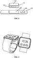
- FIG. 1 is a first structure diagram of a wearable electronic device according to an exemplary embodiment. As shown in FIG. 1 , the wearable electronic device may include:
- the body 101 When the body 101 is fixed with the connector 103, the body 101 is arranged in the accommodating space 104.
- the connector 103 can form a wearing ring.
- the body 101 When the first accommodating space 104 is empty, the body 101 is separated from the connector 103.
- a first communication module 105 is arranged in the body 101 and is configured for communication between the body 101 and external devices.
- a second communication module 106 is arranged in the connector 103 and is independent of the first communication module 105.
- the second communication module 106 is configured for communication between the connector 103 and external devices.
- the wearable electronic device may be a portable electronic device that can be worn by a user or integrated into the user's clothing or accessories.
- wearable electronic devices may include: an electronic watch supported by a wrist and includes a dial and a strap, or shoes and socks supported by a foot, or an electronic device that can be worn on a leg, or glasses, helmets, headbands and others supported by a head, or smart clothing, bags, crutches, accessories, etc.
- the wearable electronic device may have the body 101 and the connector 103.
- the body 101 may include the display module 102.
- the display area of the display module 102 may be on the surface of the body 101 and is configured to output the display contents.
- the connector 103 and the body 101 of the wearable electronic device involved in the embodiments of the present disclosure may be connected detachably. Because there is the first accommodating space 104 on the connector 103, the body 101 of the wearable electronic device during use may be arranged in the first accommodating space 104. In this way, the body 101 can be fixed on the connector 103.
- the connector 103 can form a wearing ring, therefore, when the body 101 of the wearable electronic device is fixed on the connector 103, the wearable electronic device with the body 101 may be fixed on the user's body through the wearing ring formed by the connector 103.
- the first accommodating space on the connector when the first accommodating space on the connector is empty, it means that the body is not arranged in the first accommodating space. In this case, the body of the wearable electronic device and the connector are separated. When the body of the wearable electronic device is separated from the connector, the connector can also be fixed on the user's body through the wearing ring formed by the connector.
- the body 101 has the first communication module 105 for communicating with external devices, and the connector 103 has the second communication module 106 for communicating with external devices, therefore, the body 101 and the connector 103 also can communicate with external devices respectively based on the first communication module 105 and the second communication module 106 after the body 101 and the connector 103 are separated.
- the wearable electronic device may be a smart electronic watch.
- the body 101 of the wearable electronic device may include the dial of the smart electronic watch
- the connector 103 may include the strap of the smart electronic watch.
- FIG. 2 is a schematic diagram of a smart electronic watch according to an exemplary embodiment.
- the wearable electronic device may also be a portable electronic device supported by the neck.
- the body of the wearable electronic device may be a pendant
- the connector may be a necklace that can form the wearing ring.
- the pendant may be hung around the user's neck through the necklace that forms the wearing ring.
- FIG. 3 is a structure diagram of a smart electronic watch according to an exemplary embodiment.
- the smart electronic watch may include a body 301 and a connector 302.
- a display screen is arranged on the surface of the body 301 of the smart electronic watch and is for outputting display contents.
- the first communication module may be a NFC module and is configured to perform NFC between the smart electronic watch and external devices.
- the first communication modules may be a Bluetooth communication module, a ZigBee communication module, and so on.
- the first communication module may also be a remote communication module and is configured to perform remote communication between the smart electronic watch and external devices.
- the first communication module is a Wireless Fidelity (Wi-Fi) communication module
- the body 301 may communicate with external devices, so as to realize data transmission.
- Wi-Fi Wireless Fidelity
- the body of the smart electronic watch may be removed from the first accommodating space of the connector and handed over to the administrator after the student arrives at school, and the connector can continue being worn on the wrist.
- the connector has the second communication module for communicating with external devices, therefore, some functions of the smart electronic watch can be normally used. The administrator still can send the students' situations at school to parents through the first communication module on the body.
- the user may also remove the body of the wearable electronic device from the connector, and then enter the place wearing the connector. In this way, the function of the connector can be continued on the basis of meeting the confidentiality requirements.
- the first accommodating space is arranged on the connector of the wearable electronic device to place the body of the wearable electronic device.
- the connector can form a wearing ring separately after the body is removed, therefore, the connector can be worn normally even if the body is removed from the first accommodating space on the connector.
- the body has the first communication module
- the connector has the second communication module
- the first communication module and the second communication module are independent of each other, therefore, the body and the connector can work normally as two independent parts even if the body and the connector are separated.
- a user can decide to carry the body and/or the connector according to different application scenarios, which can improve the flexibility of using the wearable electronic device and thus improve the user experience.
- the first communication module is further configured to establish a communication connection between the body and a first external device when the body is arranged in a second accommodating space on the first external device.
- the body may be arranged in the second accommodating space of the first external device, so as to establish the communication connection between the body and the first external device.
- the first communication module is a Bluetooth communication module and there is a Bluetooth module arranged in the first external device
- the body may be arranged in the second accommodating space of the first external device during use.
- a Bluetooth connection between the body and the first external device may be established based on the Bluetooth communication module of the body and the Bluetooth module of the first external device, so as to perform data transmission.
- a first contact point may also be set in the second accommodating space of the first external device, and a second contact point may also be set on the body of the wearable electronic device.
- the first contact point may come into contact with the second contact point to form an electrical connection between the body and the first external device. After the electrical connection is formed, the data transmission between the body of the wearable electronic device and the first external device may be realized.
- FIG. 4 is a second structure diagram of a wearable electronic device according to an exemplary embodiment.
- the wearable electronic device may include a body 401 and a connector 402.
- the body 401 may be removed from the connector 402 and arranged in the second accommodating space 404 of the first external device 403, so as to establish a communication connection between the body 401 and the first external device 403.
- the wearable electronic device is the smart electronic watch as an example.
- the administrator may place the body of the smart electronic watch in the second accommodating space of the first external device, so as to establish a communication connection between the body and the first external device.
- the body of the wearable electronic device when the body of the wearable electronic device is separated from the connector, the body of the wearable electronic device may be placed in the second accommodating space of the first external device, and a communication connection between the body and the first external device can be established based on the first communication module of the body. In this way, even if the body of the wearable electronic device is separated from the connector, the body and the first external device can communicate normally, and the flexibility of using the wearable electronic device can be improved.
- the first external device may also be an attendance device or a check-in device.
- a second accommodating space may be set on the attendance device or the check-in device.
- the body of the wearable electronic device may be arranged in the second accommodating space of the attendance device or the check-in device.
- a communication connection between the body and the attendance device or the check-in device may be established. After the communication connection is established successfully, the attendance device or the check-in device can directly acquire attendance information or check-in information.
- the body may further include: a first processing module, configured to switch the body from a first operating mode to a second operating mode after the body establishes the communication connection with the first external device.
- Functions that the body can perform in the second working mode are fewer than functions that the body can perform in the first operating mode.
- the wearable electronic device is the smart electronic watch as an example.
- the administrators may place the body of the smart electronic watch in the second accommodating space of the first external device, so as to establish the communication connection between the body and the first external device. It is needed to reduce the interference of the information received by the body of the smart watch on the student at school, therefore, it is required to switch the body of the smart watch from a normal mode (the first operating mode) to a campus mode (the second operating mode), so as to reduce the interferences of phone, SMS, Internet, entertainment and other functions on the student in class. Meanwhile, a studying function can be used normally.
- the wearable electronic device when the body of the wearable electronic device is in the first operating mode, the power consumption of the wearable electronic device is higher than that in the second operating mode. Since the second operating mode is a mode with low utilization, the wearable electronic device may enter the second operating mode with low power consumption from the first operating mode with high power consumption by disabling one or more functions of the body or reducing a working frequency of the body.
- the body may be switched from the first operating mode with more functions to the second operating mode with fewer functions. In this way, on the basis of ensuring the normal use of the body of the wearable electronic device, the interference of unnecessary functions on a user is reduced.
- the first processing module is further configured to switch the body from the second operating mode to the first operating mode after determining that the communication connection between the body and the first external device is disconnected.
- the wearable electronic device is the smart electronic watch as an example.
- the smart electronic watch may be switched from the second operating mode with fewer functions to the first operating mode with more functions in order to guarantee the normal use of the smart electronic watch.
- the body may be automatically switched from the second operating mode with fewer functions to the first operating mode with more functions. In this way, the flexibility of using the wearable electronic device is improved while ensuring the normal use of the body of the wearable electronic device.
- a power supply connection between the body and the first external device may also be established, so as to charge the body through the first external device.
- the second communication module is further configured to establish the communication connection between the connector and a second external device when the distance between the connector and the second external device is less than a preset distance threshold.
- a wearable electronic device may include a body and a connector.
- the connector and the body of the wearable electronic device may be connected detachably.
- the connector has a second communication module for communicating with an external device, therefore, when the connector of the wearable electronic device is used alone, a communication connection between the connector and the second external device can be established through the second communication module.
- a power supply connection between the body and the second external device may also be established, so as to charge the connector through the second external device.
- the second communication module may be a NFC module and may establish a communication connection between the connector and the second external device when the distance between the connector and the second external device is less than a preset distance threshold.
- the connector can form a wearing ring, therefore, when the body of the wearable electronic device is separated from the connector, the connector can continue being fixed on the user's body through the wearing ring. Based on the structure of the wearable electronic device in the embodiments of the present disclosure, the connector can still be used normally when the body of the wearable electronic device is separated from the connector.
- the second communication module may include: an NFC chip, configured to simulate the connector into an NFC card.
- the NFC card is configured to perform NFC between the NFC card and a card reading device.
- the NFC chip is a chip configured to realize contactless data transmission between devices. Since the NFC chip is simple in structure, small in size and slice-shaped, it can be simply and conveniently embedded in the connector. During use, the connector may be simulated as a non-contact NFC card for use. In other optional embodiments, the NFC chip may be connected to memory in which authentication information is stored in advance to authenticate access permission of a user. Taking that the connector is simulated as an access control card for example. Access control authentication information may be stored in the memory for authenticating whether the user has the authority to open the access control.
- the NFC chip may be arranged in the connector to simulate the connector as the non-contact NFC cards for use, such as an access control card, a bank card and a bus card.
- the connector which is simulated as the NFC card, may be placed close to the card reading device, so as to perform NFC interaction with the card reading device.
- the card reading device may be equipped with an NFC card swiping system, so that the card reading device can perform NFC interaction with the connector simulated as the NFC card through the NFC card swiping system.
- the NFC card swiping system equipped in the card reading device may be an access control system, a payment system, a public traffic system, and so on.
- the connector when the NFC card swiping system equipped in the card reading device is the access control system, the connector may be simulated as the access control card.
- the connector When the NFC card swiping system equipped in the card reading device is the payment system, the connector may be simulated as the bank card.
- the connector When the NFC card swiping system equipped in the card reading device is the public traffic system, the connector may be simulated as the bus card.
- FIG. 5 is a structure diagram of a connector according to an exemplary embodiment. As shown in FIG. 5 , the body 501 and the connector 502 of the wearable electronic device are separated, and the connector 502 is equipped with the NFC chip 503.
- FIG. 6 is a schematic diagram of a connector in use according to an exemplary embodiment. As shown in FIG. 6 , when the connector 601 and the body of the wearable electronic device are separated, the connector 601 may form a wearing ring surrounding a user's wrist. The connector 601 is equipped with the NFC chip, therefore, card swiping can be performed based on the NFC chip when the connector is placed near the card reading device 602 during use.
- the connector equipped with the NFC chip may be simulated as the NFC card that may perform near field wireless communication with the card reading device. In this way, even though the body of the wearable electronic device is separated from the connector, the connector may also be used separatel y.
- the wearable electronic device may further include a fixer on the connector.
- the fixer is configured to lock a first fixing point and a second fixing point on the connector, so that the connector forms the wearing ring.
- the fixer may be a buckle structure.
- the connector may further include a detecting module.
- the detecting module is configured to detect, after the connector forms the wearing ring, whether the formed wearing ring is in a separated state, and when the wearing ring is in the separated state, detect whether the duration of the wearing ring in the separated state is greater than a first preset duration.
- the second communication module is further configured to send a third prompt message to the terminal device bound to the wearable electronic device when the duration of the wearing ring in the separated state is greater than the first preset duration.
- the detecting module is further configured to detect whether the first fixing point and the second fixing point on the connector are locked. When the first fixing point and the second fixing point are locked, it is determined that the connector forms the wearing ring. When the first fixing point and the second fixing point are separated, it can be determined that the wearing ring formed by the connector is in the separated state.
- the detecting module is further configured to detect, after the connector forms the wearing ring, whether the connector is in an immobile state.
- the second communication module is further configured to send a fourth prompt message to the terminal device bound to the wearable electronic device when the duration of the connector in the immobile state is greater than a second preset duration.
- the second communication module may also be a remote communication module, for example, a Subscriber Identification Module (SIM) card, a Wi-Fi communication module, etc.
- SIM Subscriber Identification Module
- a third prompt message may be automatically sent to the terminal device bound to the wearable electronic device.
- a fourth prompt message may be automatically sent to the terminal device bound to the wearable electronic device.
- a warning message can be sent to the terminal device bound to the wearable electronic device timely, so that a user holding the terminal device can know that the connector is not normally worn and make corresponding countermeasures.
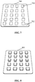
- FIG. 7 is a first structure diagram of an electronic device according to an exemplary embodiment. As shown in FIG. 7 , the electronic device 700 may include:
- the plurality of second accommodating spaces 701 may be set on the electronic device 700 to accommodate the body of the wearable electronic device.
- the electronic device 700 may be the first external device in the above embodiments.
- the communication connection between the body and the electronic device 700 may be established based on the first communication module of the body and the third communication module 703 of the electronic device 700.
- FIG. 8 is a second structure diagram of an electronic device according to an exemplary embodiment. As shown in FIG. 8 , the body of the wearable electronic device is accommodated in all the second accommodating spaces of the electronic device 801.
- the first contact point may also be set in the second accommodating space of the electronic device, and the second contact point may also be set on the body of the.
- the first contact point may come into contact with the second contact point to form the electrical connection between the body and the electronic device. After the electrical connection is formed, data transmission between the body of the wearable electronic device and the electronic device may be realized.
- the bodies of the plurality of wearable electronic devices may be accommodated, and the communication connection between the electronic device and each body may be established through the third communication module. In this way, the bodies of the plurality of wearable electronic devices can be controlled based on one electronic device.
- the electronic device may further include: a third processing module, configured to determine whether the communication connection between the electronic device including the third communication module and the body is established successfully.
- the third communication module connected with the third processing module, is further configured to send a first prompt message to a terminal device bound to the wearable electronic device when a communication connection between the electronic device including the third communication module and the body is established successfully.
- the first prompt message may be sent to the terminal device bound to the wearable electronic device.
- the first prompt message may be either a message representing that the communication connection between the electronic device and the body is established successfully, or check-in information generated based on a state that the communication connection between the electronic device and the body is established successfully.
- the electronic device may send the first prompt message to the terminal device through a network, for example, by a mail and a web page link.
- the electronic device may also send the first prompt message to the terminal device through SMS.
- whether the electronic device receives a connection request from the body of the wearable electronic device may be determined based on the third processing module of the electronic device.
- a request response may be sent to the body in response to receiving the connection request.
- the communication connection between the body of the wearable electronic device and the electronic device may be established in response to determining that the body receives the request response.
- whether the first contact point comes into contact with the second contact point may be determined based on the third processing module of the electronic device.
- the first contact point comes into contact with the second contact point, it can be determined that the communication connection between the electronic device and the body is established successfully.
- the first prompt message may be sent to the terminal device bound to the wearable electronic device based on the third communication module connected with the third processing module.
- the wearable electronic device is the smart electronic watch used by the student for example. Since school does not allow a student to use a smart electronic watch, the student can remove the body of the smart electronic watch from the first accommodating space of the connector and hand over the body to an administrator after arriving at school. After getting the body, the administrator may place the body in the second accommodating space of the electronic device to establish a communication connection between the body and the electronic device, so as to realize the function of sending the student's situation after the body is separated from the connector.
- the terminal device may be an external device that is different from the body and the electronic device. For example, the terminal device may be an electronic device held by parents for receiving and displaying information sent from the electronic device of the student.
- the embodiments of the present disclosure also provide a system for information processing.
- the system for information processing may include: the body of the wearable electronic device, the electronic device and the terminal device.
- the body of the wearable electronic device may be arranged in the second accommodating space of the electronic device to establish the communication connection between the body and the electronic device.
- the first prompt message may be sent to the terminal device.
- a connection request may be sent to the electronic device based on the body.
- the electronic device determines whether the connection request sent by the body of the wearable electronic device is received.
- the electronic device may send a request response to the body.
- the body may establish the communication connection with the electronic device based on the request response.
- the electronic device may send the first prompt message indicating the successful connection to the terminal device.
- whether a distance between the connector and the second external device is less than a preset distance threshold may also be determined.
- the distance between the connector and the second external device is less than the preset distance threshold, the communication connection between the connector and the second external device is established, and the connector may communicate with the second external device.
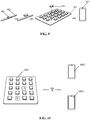
- FIG. 9 is a structure diagram of a system for information processing according to an exemplary embodiment.
- the system for information processing may include: a body 901 of a smart electronic watch, an electronic device 903, and a terminal device 904.
- the smart electronic watch includes the body 901 and the connector 902.
- the body 901 may be removed from the connector 901 and arranged in the second accommodating space of the electronic device 903 to establish a communication connection between the body 901 and the electronic device 903.
- the first prompt message may be sent to the terminal device 904.
- a first prompt message may be sent to the terminal device bound to the wearable electronic device through the third communication module connected with the third processing module.
- the first prompt message may be a message representing that the communication connection between the body and the electronic device is successful.
- the third communication module is further configured to send a second prompt message different from the first prompt message to the terminal device when the communication connection between the electronic device including the third communication module and the body fails to be established.
- the third processing module is further configured to determine at a preset time whether the communication connection between the electronic device and the body is established successfully, and send the second prompt message different from the first prompt message to the terminal device when the communication connection between the electronic device and the body fails to be established.
- the preset time may be set according to needs, for example, 9:00 am and 2:00 pm.
- the preset time may be set as the deadline for the student to attend class. If the communication connection between the body of the smart electronic watch and the electronic device is successfully established before the deadline, it means that the student arrives at school on time and has handed over the body of the smart electronic watch to the administrator. If the communication connection between the body of the smart electronic watch and the electronic device fails to be established after the deadline, it means that the student did not hand over the body of the smart electronic watch to the administrator on time. In this case, it can be determined that the student did not arrive at school on time. It is needed to send a second prompt message to the terminal device held by the parents. The second prompt message may be either a message representing that the communication connection between the body and the electronic device fails to be established, or a prompt message representing that the student fails to arrive at school on time generated based on a state that the connection between the electronic device and the body fails.
- FIG. 10 is a first schematic diagram of interactions between an electronic device and a terminal device according to an exemplary embodiment.
- a second accommodating space A and a second accommodating space B on the electronic device 1001 are empty, which indicates that the bodies of the smart electronic watches of the student A and the student B are not placed in the corresponding second accommodating spaces.
- the electronic device 1001 may send prompt messages respectively to the first terminal device 1002 bound to the smart electronic watch owned by the student A and the second terminal device 1003 bound to the smart electronic watch owned by the student B, so as to inform the parents of the student A and the student B about their failure to arrive at school on time.
- the electronic device 1001 may send the prompt messages to the first terminal device 1002 and the second terminal device 1003 through a Wi-Fi network.
- the second prompt message may be sent to the terminal device bound to the wearable electronic device through the third communication module connected with the third processing module.
- the second prompt message may be a prompt message representing that the student fails to arrive at school on time.
- the attendance of student may be determined based on the state of the communication connection between the body and the electronic device, and the student's situation may be sent to the terminal device bound to the wearable electronic device, which can not only ensure that the student obeys school rules, but also enable the parents to timely know the situation of the student at school.
- the third communication module is further configured to send input information received from the body to the terminal device.
- the input information may be determined by the body based on an input request of an input device acting on the body.
- the body may send information to the electronic device.
- the body may determine input information based on the input request received by the input device of the body, and send the input information to the electronic device.
- the electronic device may send the input information to the terminal device through the communication connection.
- the input request may be input by the input device, acting on the body, of the administrator.
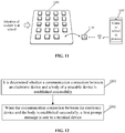
- FIG. 11 is a second schematic diagram of interactions between an electronic device and a terminal device according to an exemplary embodiment.
- the administrator may input the input information to be sent through the input device of the body 1102 of the student A placed on the electronic device 1101, and send the input information to the terminal device 1103 of the parents of the student A through the electronic device 1101.
- a user may send information to the electronic device based on the body and forward the information sent by the body to the terminal device through the electronic device.
- the parents can learn about the situation of the student at school from the administrator.
- FIG. 12 is a flowchart of a method for information processing according to an exemplary embodiment. As shown in FIG. 12 , the method is applied to an electronic device, and may include the following operations.
- Whether the communication connection between the electronic device and the body is established successfully may be determined based on the third processing module of the electronic device.
- the first prompt message may be sent to the terminal device bound to the wearable electronic device.
- the method may further include that: it is determined whether the electronic device receives the connection request from the body of the wearable electronic device; a request response is sent to the body in response to receiving the connection request; and the communication connection between the body of the wearable electronic device and the electronic device may be established in response to determining that the body receives the request response.
- the communication connection between the electronic device and the body is established based on a first contact point set in the second accommodating space of the electronic device and a second contact point set on the body of the wearable electronic device, whether the first contact point comes into contact with the second contact point may be determined.
- the first contact point comes into contact with the second contact point, it can be determined that the communication connection between the electronic device and the body is established successfully.
- the first prompt message may be sent to the terminal device bound to the wearable electronic device.
- the wearable electronic device is the smart electronic watch used by the student for example. Since school does not allow a student to use a smart electronic watch, the student may remove the body of the smart electronic watch from the first accommodating space of the connector and hand over the body to an administrator after arriving at school. After getting the body, the administrator may place the body in the second accommodating space of the electronic device to establish a communication connection between the body and the electronic device, so that the function of sending the student's situation can also be realized after the body is separated from the connector.
- a first prompt message may be sent to a terminal device bound to the wearable electronic device.
- the first prompt message may be a message representing that the communication connection between the body and the electronic device is successful.
- the attendance of student may be determined based on the state of the communication connection between the body and the electronic device, and the student's situation may be sent to the terminal device bound to the wearable electronic device, which can not only ensure that the student obeys school rules, but also enable the parents to timely know the situation of the student at school.
- the method may further include that: when the communication connection between the electronic device and the body fails to be established, a second prompt message different from the first prompt message may be sent to the terminal device.
- the method may further include that: it is determined at a preset time whether the communication connection between the electronic device and the body is established successfully. When the communication connection between the electronic device and the body fails to be established, the second prompt message different from the first prompt message may be sent to the terminal device.
- the preset time may be set according to needs, for example, 9:00 am and 2:00 pm.
- the preset time may be set as the deadline for the student to attend class. If the communication connection between the body of the smart electronic watch and the electronic device is successfully established before the deadline, it means that the student arrived at school on time and handed over the body of the smart electronic watch to the administrator. If the communication connection between the body of the smart electronic watch and the electronic device fails to be established after the deadline, it means that the student did not handover the body of the smart electronic watch to the administrator on time. In this case, it may be determined that the student did not arrive at school on time, and it is needed to send a second prompt message to the terminal device held by the parents.
- the second prompt message may be either a message representing that the communication connection between the body and the electronic device fails to be established, or a prompt message representing that the student fails to arrive at school on time generated based on the state that the connection between the electronic device and the body fails.
- the second prompt message may be sent to the terminal device bound to the wearable electronic device.
- the second prompt message may be the prompt message representing that the student fails to arrive at school on time.
- the attendance of student may be determined based on the state of the communication connection between the body and the electronic device, and the student's situation may be sent to the terminal device bound to the wearable electronic device, which can not only ensure that the student obeys school rules, but also enable the parents to timely know the situation of the student at school.
- the method may further include that:
- the body may send information to the electronic device.
- the body may send the input information determined based on the input request of the input device acting on the body to the electronic device.
- the electronic device may send the received input information to the terminal device based on the communication connection.
- the input request may be input by the input device, acting on the body, of the administrator.
- a user may send information to the electronic device based on the body and forward the information sent by the body to the terminal device through the electronic device.
- the parents can learn about the situation of the student at school.
- the method may further include that: based on the state of the communication connection between the electronic device and the body, check-in information is determined, and the check-in information is sent to the check-in system.
- the state of the communication connections may include the state that the communication connection between the electronic device and the body is established successfully and the state that the communication connection between the electronic device and the body fails to be established.
- the check-in information may be generated based on the state of the communication connection between the electronic device and the body. For example, when the communication connection between the electronic device and the body is established successfully, first check-in information may be generated, and the first check-in information may represent successful check-in. When the communication connection between the electronic device and the body fails to be established, second check-in information may be generated, and the second check-in information may represent failed check-in. After the check-in information is determined, the determined check-in information may be sent to the check-in system and stored.
- the check-in information of a student may be determined based on the state of connection between the electronic device and the smart electronic watch and sent to the check-in system of school. In this way, information interconnection among the smart electronic watch, the electronic device and the check-in system can be realized, and data transmission and management can be performed, so as to realize function expansion of the smart electronic watch.
- information interconnection between the wearable electronic device and the check-in system can be realized by establishing the communication connection between the body of the wearable electronic device and the electronic device, determining the check-in information based on the state of the communication connection of the communication connection, sending the check-in information to the check-in system, and taking the electronic device as a transferring device.
- the electronic device Compared with the current manual manner of attendance management, it is more intelligent.
- FIG. 13 is a block diagram of a hardware structure of a device for information processing according to an exemplary embodiment.
- the device 1300 may be a mobile phone, a computer, a digital broadcast terminal, a messaging device, a gaming console, a tablet, a medical device, exercise equipment and a personal digital assistant.
- the device 1300 may include one or more of the following components: a processing component 1302, a memory 1304, a power component 1306, a multimedia component 1308, an audio component 1310, an Input/Output (I/O) interface 1312, a sensor component 1314, and a communication component 1316.
- a processing component 1302 a memory 1304, a power component 1306, a multimedia component 1308, an audio component 1310, an Input/Output (I/O) interface 1312, a sensor component 1314, and a communication component 1316.
- the processing component 1302 typically controls overall operations of the device 1300, such as the operations associated with display, telephone calls, data communications, camera operations, and recording operations.
- the processing component 1302 may include one or more processors 1320 to execute instructions to perform all or part of the steps in the above method.
- the processing component 1302 may include one or more modules which facilitate interaction between the processing component 1302 and the other components.
- the processing component 1302 may include a multimedia module to facilitate interaction between the multimedia component 1308 and the processing component 1302.
- the memory 1304 is configured to store various types of data to support the operation of the device 1300. Examples of such data include instructions for any application programs or methods operated on the device 1300, contact data, phonebook data, messages, pictures, video, etc.
- the memory 1304 may be implemented by any type of volatile or non-volatile memory devices, or a combination thereof, such as a Static Random Access Memory (SRAM), an Electrically Erasable Programmable Read-Only Memory (EEPROM), an Erasable Programmable Read-Only Memory (EPROM), a Programmable Read-Only Memory (PROM), a Read-Only Memory (ROM), a magnetic memory, a flash memory, and a magnetic or optical disk.
- SRAM Static Random Access Memory
- EEPROM Electrically Erasable Programmable Read-Only Memory
- EPROM Erasable Programmable Read-Only Memory
- PROM Programmable Read-Only Memory
- ROM Read-Only Memory
- magnetic memory a magnetic memory
- flash memory and a magnetic or optical disk
- the power component 1306 is configured to provide power for various components of the device 1300.
- the power component 1306 may include a power management system, one or more power supplies, and other components associated with generation, management and distribution of power for the device 1300.
- the multimedia component 1308 may include a screen providing an output interface between the device 1300 and a user.
- the screen may include a Liquid Crystal Display (LCD) and a Touch Panel (TP). If the screen includes the TP, the screen may be implemented as a touch screen to receive an input signal from the user.
- the TP includes one or more touch sensors to sense touches, swipes and gestures on the TP. The touch sensors may not only sense a boundary of a touch or swipe action but also detect a duration and pressure associated with the touch or swipe action.
- the multimedia component 1308 includes a front camera and/or a rear camera.
- the front camera and/or the rear camera may receive external multimedia data when the device 1300 is in an operation mode, such as a photographing mode or a video mode.
- an operation mode such as a photographing mode or a video mode.
- Each of the front camera and the rear camera may be a fixed optical lens system or have focusing and optical zooming capabilities.
- the audio component 1310 is configured to output and/or input an audio signal.
- the audio component 1310 includes a Microphone (MIC), and the MIC is configured to receive an external audio signal when the device 1300 is in the operation mode, such as a call mode, a recording mode and a voice recognition mode.
- the received audio signal may further be stored in the memory 1304 or sent through the communication component 1316.
- the audio component 1310 further includes a speaker configured to output the audio signal.
- the I/O interface 1312 is configured to provide an interface between the processing component 1302 and a peripheral interface module.
- the peripheral interface module may be a keyboard, a click wheel, a button, etc.
- the button may include, but not limited to: a home button, a volume button, a starting button and a locking button.
- the sensor component 1314 may include one or more sensors configured to provide status assessment in various aspects for the device 1300. For instance, the sensor component 1314 may detect an on/off status of the device 1300 and relative positioning of components, such as a display and small keyboard of the device 1300, and the sensor component 1314 may further detect a change in a position of the device 1300 or a component of the device 1300, presence or absence of contact between the user and the device 1300, orientation or acceleration/deceleration of the device 1300 and a change in temperature of the device 1300.
- the sensor component 1314 may include a proximity sensor configured to detect presence of an object nearby without any physical contact.
- the sensor component 1314 may also include a light sensor, such as a Complementary Metal Oxide Semiconductor (CMOS) or Charge Coupled Device (CCD) image sensor, configured for use in an imaging application.
- CMOS Complementary Metal Oxide Semiconductor
- CCD Charge Coupled Device
- the sensor component 1314 may also include an acceleration sensor, a gyroscope sensor, a magnetic sensor, a pressure sensor or a temperature sensor.
- the communication component 1316 is configured to facilitate wired or wireless communication between the device 1300 and another device.
- the device 1300 may access a communication-standard-based wireless network, such as WI-FI, a 2G or 3G network or a combination thereof.
- the communication component 1316 receives a broadcast signal or broadcast associated information from an external broadcast management system through a broadcast channel.
- the communication component 1316 further includes an NFC module to facilitate short-range communication.
- the NFC module may be implemented based on a Radio Frequency Identification (RFID) technology, an Infrared Data Association (IrDA) technology, an Ultra-WideBand (UWB) technology, a Bluetooth (BT) technology and another technology.
- RFID Radio Frequency Identification
- IrDA Infrared Data Association
- UWB Ultra-WideBand
- BT Bluetooth
- the device 1300 may be implemented by one or more Application Specific Integrated Circuits (ASICs), Digital Signal Processors (DSPs), Digital Signal Processing Devices (DSPDs), Programmable Logic Devices (PLDs), Field Programmable Gate Arrays (FPGAs), controllers, micro-controllers, microprocessors or other electronic components, and is configured to execute the above method.
- ASICs Application Specific Integrated Circuits
- DSPs Digital Signal Processors
- DSPDs Digital Signal Processing Devices
- PLDs Programmable Logic Devices
- FPGAs Field Programmable Gate Arrays
- controllers micro-controllers, microprocessors or other electronic components, and is configured to execute the above method.
- a non-transitory computer-readable storage medium storing instructions, such as the memory 1304 storing instructions, and the instructions may be executed by the processor 1320 of the device 1300 to implement the abovementioned method.
- the non-temporary computer-readable storage medium may be a Read-Only Memory (ROM), a Random Access Memory (RAM), a Compact Disc Read-Only Memory (CD-ROM), a magnetic tape, a floppy disc, an optical data storage device and the like.
- a non-transitory computer-readable storage medium is provided.
- the device for information processing can perform the information management method.
- the method is applied to an electronic device, and may include the following operations.
Landscapes
- Engineering & Computer Science (AREA)
- Computer Hardware Design (AREA)
- Theoretical Computer Science (AREA)
- Computer Networks & Wireless Communication (AREA)
- Signal Processing (AREA)
- Physics & Mathematics (AREA)
- General Physics & Mathematics (AREA)
- Human Computer Interaction (AREA)
- General Engineering & Computer Science (AREA)
- Telephone Function (AREA)
Abstract
Description
- The present disclosure relates to the field of computer communications, and more particularly to a method for information processing, a wearable electronic device, an electronic device, and a storage medium.
- With development of electronics technology, more and more types of electronic products are applied. More and more people use wearable electronic devices because they are easy to carry. Taking that a wearable electronic device is a smart electronic watch for example, many parents equip their children with smart electronic watches in order to ensure safety of children and keep track of their children at any time.
- Sometimes students may bring smart electronic watches to school, but are not allowed to use the smart electronic watches in public due to possible interference with normal studying and teaching order. As a result, many students are restricted from using smart electronic watches at school, or have to use the smart electronic watches secretly. As a result, parents cannot keep track of their children through the smart electronic watches.
- According to a first aspect of the embodiments of the present disclosure, a wearable electronic device may include: a body which includes a display module and a connector, which has a first accommodating space. A display area of the display module is on a surface of the body and is configured to output display contents.
- When the body is fixed with the connector, the body is in the accommodating space. The connector can form a wearing ring. When the first accommodating space is empty, the body is separated from the connector. A first communication module is arranged in the body and is configured for the communication between the body and external devices. A second communication module is arranged in the connector and is independent of the first communication module, and is for communication between the connector and external devices.
- Optionally, the first communication module is further configured to establish a communication connection between the body and a first external device when the body is in a second accommodating space on the first external device.
- Optionally, the body may further include:
a first processing module, configured to switch the body from a first operating mode to a second operating mode after the body establishes the communication connection with the first external device. - Functions that the body can perform in the second working mode are fewer than functions that the body can perform in the first operating mode.
- Optionally, the first processing module is further configured to switch the body from the second operating mode to the first operating mode after determining that the communication connection between the body and the first external device is disconnected.
- Optionally, the second communication module is further configured to establish a communication connection between the connector and a second external device when a distance between the connector and the second external device is less than a preset distance threshold.
- Optionally, the second communication module may include:
a Near Field Communication (NFC) chip, configured to simulate the connector into an NFC card, where the NFC card is configured to perform NFC between the NFC card and a card reading device. - According to a second aspect of the embodiments of the present disclosure, an electronic device is provided, which may include:
- a plurality of second accommodating spaces, each configured to accommodate the body of the wearable electronic device;
- a third communication module, configured to establish the communication connection with the body when the body is arranged in the second accommodating space.
- Optionally, the electronic device may further include:
a third processing module, configured to determine whether the communication connection between the electronic device including the third communication module and the body is established successfully. - The third communication module may be connected with the third processing module, and is further configured to send a first prompt message to a terminal device bound to the wearable electronic device when the communication connection between the electronic device including the third communication module and the body is established successfully.
- Optionally, the third communication module is further configured to send a second prompt message different from the first prompt message to the terminal device when the communication connection between the electronic device including the third communication module and the body fails to be established.
- Optionally, the third communication module is further configured to send input information received from the body to the terminal device. The input information may be determined by the body based on an input request of an input device acting on the body.
- According to a third aspect of the embodiments of the present disclosure, a method for information processing is applicable to the electronic device in the second aspect, and may include that:
- it is determined whether the communication connection between the electronic device and the body of the wearable device is established successfully; and
- when the communication connection between the electronic device and the body is established successfully, the first prompt message is sent to the terminal device.
- Optionally, the method may further include that:
when the communication connection between the electronic device and the body fails to be established, the second prompt message different from the first prompt message is sent to the terminal device. - Optionally, the method may further include that:
- the input information sent by the body is received. The input information may be determined by the body based on the input request of the input device acting on the body; and
- the input information is sent to the terminal device bound to the wearable electronic device.
- Optionally, the method may further include that:
check-in information is determined based on a state of the communication connection between the electronic device and the body, and the check-in information is sent to a check-in system. - According to a fourth aspect of the embodiments of the present disclosure, a non-transitory computer-readable storage medium has stored instructions therein that, when executed by a processor of an electronic device, cause the electronic device to implement the method for information processing in the third aspect.
- The technical solutions provided in the embodiments of the present disclosure may have the following beneficial effects.
- It can be seen from the above embodiments that, a first accommodating space may be set on a connector of a wearable electronic device to accommodate a body of the wearable electronic device. In the first aspect, the connector can form a wearing ring separately after the body is removed, therefore, the connector can be normally worn even if the body is removed from the first accommodating space on the connector. In the second aspect, the body has the first communication module, the connector has the second communication module, and the first communication module and the second communication module are independent of each other, therefore, the body and the connector can work normally as two independent parts even if the body and the connector are separated. In the third aspect, users can decide to carry the body and/or the connector according to different application scenarios, which can improve the flexibility of using the wearable electronic device and thus improve the user experience.
- It is to be understood that the above general descriptions and detailed descriptions below are only exemplary and explanatory and not intended to limit the present disclosure.
- The accompanying drawings, which are incorporated in and constitute a part of this specification, illustrate embodiments consistent with the present disclosure and, together with the description, serve to explain the principles of the present disclosure.
-
FIG. 1 is a first structure diagram of a wearable electronic device according to an exemplary embodiment. -
FIG. 2 is a schematic diagram of a smart electronic watch according to an exemplary embodiment. -
FIG. 3 is a structure diagram of a smart electronic watch according to an exemplary embodiment. -
FIG. 4 is a second structure diagram of a wearable electronic device according to an exemplary embodiment. -
FIG. 5 is a structure diagram of a connector according to an exemplary embodiment. -
FIG. 6 is a schematic diagram of a connector in use according to an exemplary embodiment. -
FIG. 7 is a first structure diagram of an electronic device according to an exemplary embodiment. -
FIG. 8 is a second structure diagram of an electronic device according to an exemplary embodiment. -
FIG. 9 is a structure diagram of a system for information processing according to an exemplary embodiment. -
FIG. 10 is a first schematic diagram of interactions between an electronic device and a terminal device according to an exemplary embodiment. -
FIG. 11 is a second schematic diagram of interactions between an electronic device and a terminal device according to an exemplary embodiment. -
FIG. 12 is a flowchart of a method for information processing according to an exemplary embodiment. -
FIG. 13 is a block diagram of a hardware structure of a device for information processing according to an exemplary embodiment. - Reference will now be made in detail to exemplary embodiments, examples of which are illustrated in the accompanying drawings. The following description refers to the accompanying drawings in which the same numbers in different drawings represent the same or similar elements unless otherwise represented. The implementations set forth in the following description of exemplary embodiments do not represent all implementations consistent with the present disclosure. Instead, they are merely examples of apparatuses and methods consistent with aspects related to the present disclosure as recited in the appended claims.
- The terms used in the present disclosure are for describing particular embodiments only, and are not intended to limit the present disclosure. The singular forms "a/an", "the" and "this" used in the present disclosure and the appended claims are also intended to include the plural forms unless the context clearly indicates other meanings. It is to be understood that the term "and/or" as used herein refers to and includes any or all possible combinations of one or more associated listed items.
- It is to be understood that although the terms first, second, third, etc. may be used to describe various information in the present disclosure, the information should not be limited to these terms. The terms are only used to distinguish the same type of information from each other. For example, without departing from the scope of the present disclosure, the first information may also be referred to as second information, and similarly, the second information may also be referred to as first information. Depending on the context, the word "if" as used herein may be interpreted as "during" or "when" or "in response to determination".
-
FIG. 1 is a first structure diagram of a wearable electronic device according to an exemplary embodiment. As shown inFIG. 1 , the wearable electronic device may include: - a
body 101, which includes adisplay module 102. A display area of thedisplay module 102 is on the surface of thebody 101 and is configured to output display contents; and - a
connector 103, which has a firstaccommodating space 104. - When the
body 101 is fixed with theconnector 103, thebody 101 is arranged in theaccommodating space 104. Theconnector 103 can form a wearing ring. When the firstaccommodating space 104 is empty, thebody 101 is separated from theconnector 103. - A
first communication module 105 is arranged in thebody 101 and is configured for communication between thebody 101 and external devices. - A
second communication module 106 is arranged in theconnector 103 and is independent of thefirst communication module 105. Thesecond communication module 106 is configured for communication between theconnector 103 and external devices. - The wearable electronic device may be a portable electronic device that can be worn by a user or integrated into the user's clothing or accessories. For example, wearable electronic devices may include: an electronic watch supported by a wrist and includes a dial and a strap, or shoes and socks supported by a foot, or an electronic device that can be worn on a leg, or glasses, helmets, headbands and others supported by a head, or smart clothing, bags, crutches, accessories, etc.
- In the embodiments of the present disclosure, the wearable electronic device may have the
body 101 and theconnector 103. Thebody 101 may include thedisplay module 102. The display area of thedisplay module 102 may be on the surface of thebody 101 and is configured to output the display contents. Theconnector 103 and thebody 101 of the wearable electronic device involved in the embodiments of the present disclosure may be connected detachably. Because there is the firstaccommodating space 104 on theconnector 103, thebody 101 of the wearable electronic device during use may be arranged in the firstaccommodating space 104. In this way, thebody 101 can be fixed on theconnector 103. Theconnector 103 can form a wearing ring, therefore, when thebody 101 of the wearable electronic device is fixed on theconnector 103, the wearable electronic device with thebody 101 may be fixed on the user's body through the wearing ring formed by theconnector 103. - In an optional embodiment, when the first accommodating space on the connector is empty, it means that the body is not arranged in the first accommodating space. In this case, the body of the wearable electronic device and the connector are separated. When the body of the wearable electronic device is separated from the connector, the connector can also be fixed on the user's body through the wearing ring formed by the connector.
- The
body 101 has thefirst communication module 105 for communicating with external devices, and theconnector 103 has thesecond communication module 106 for communicating with external devices, therefore, thebody 101 and theconnector 103 also can communicate with external devices respectively based on thefirst communication module 105 and thesecond communication module 106 after thebody 101 and theconnector 103 are separated. The wearable electronic device may be a smart electronic watch. In this case, thebody 101 of the wearable electronic device may include the dial of the smart electronic watch, while theconnector 103 may include the strap of the smart electronic watch.FIG. 2 is a schematic diagram of a smart electronic watch according to an exemplary embodiment. - In an optional embodiment, the wearable electronic device may also be a portable electronic device supported by the neck. In this case, the body of the wearable electronic device may be a pendant, while the connector may be a necklace that can form the wearing ring. During use, the pendant may be hung around the user's neck through the necklace that forms the wearing ring.
- Taking that the wearable electronic device is a smart electronic watch as an example,
FIG. 3 is a structure diagram of a smart electronic watch according to an exemplary embodiment. As shown inFIG. 3 , the smart electronic watch may include abody 301 and aconnector 302. A display screen is arranged on the surface of thebody 301 of the smart electronic watch and is for outputting display contents. There is a first communication module arranged on thebody 301, and there is a second communication module arranged on theconnector 302. The first communication module may be a NFC module and is configured to perform NFC between the smart electronic watch and external devices. For example, the first communication modules may be a Bluetooth communication module, a ZigBee communication module, and so on. In other optional embodiments, the first communication module may also be a remote communication module and is configured to perform remote communication between the smart electronic watch and external devices. For example, when the first communication module is a Wireless Fidelity (Wi-Fi) communication module, thebody 301 may communicate with external devices, so as to realize data transmission. - In the case of students using smart electronic watches, since school does not allow students to use the smart electronic watches, the body of the smart electronic watch may be removed from the first accommodating space of the connector and handed over to the administrator after the student arrives at school, and the connector can continue being worn on the wrist. The connector has the second communication module for communicating with external devices, therefore, some functions of the smart electronic watch can be normally used. The administrator still can send the students' situations at school to parents through the first communication module on the body.
- In other optional embodiments, if a user wearing the wearable electronic device needs to enter a place with high confidentiality requirements, the user may also remove the body of the wearable electronic device from the connector, and then enter the place wearing the connector. In this way, the function of the connector can be continued on the basis of meeting the confidentiality requirements.
- In the embodiments of the present disclosure, the first accommodating space is arranged on the connector of the wearable electronic device to place the body of the wearable electronic device. In the first aspect, the connector can form a wearing ring separately after the body is removed, therefore, the connector can be worn normally even if the body is removed from the first accommodating space on the connector. In the second aspect, the body has the first communication module, the connector has the second communication module, and the first communication module and the second communication module are independent of each other, therefore, the body and the connector can work normally as two independent parts even if the body and the connector are separated. In the third aspect, a user can decide to carry the body and/or the connector according to different application scenarios, which can improve the flexibility of using the wearable electronic device and thus improve the user experience.
- In other optional embodiments, the first communication module is further configured to establish a communication connection between the body and a first external device when the body is arranged in a second accommodating space on the first external device.
- Since there is the first communication module arranged on the body of the wearable electronic device, when the body of the wearable electronic device is used alone, the body may be arranged in the second accommodating space of the first external device, so as to establish the communication connection between the body and the first external device. Taking that the first communication module is a Bluetooth communication module and there is a Bluetooth module arranged in the first external device, the body may be arranged in the second accommodating space of the first external device during use. In this case, a Bluetooth connection between the body and the first external device may be established based on the Bluetooth communication module of the body and the Bluetooth module of the first external device, so as to perform data transmission.
- In other optional embodiments, a first contact point may also be set in the second accommodating space of the first external device, and a second contact point may also be set on the body of the wearable electronic device. In this case, after the body is arranged in the second accommodating space, the first contact point may come into contact with the second contact point to form an electrical connection between the body and the first external device. After the electrical connection is formed, the data transmission between the body of the wearable electronic device and the first external device may be realized.
-
FIG. 4 is a second structure diagram of a wearable electronic device according to an exemplary embodiment. As shown inFIG. 4 , the wearable electronic device may include abody 401 and aconnector 402. During use, thebody 401 may be removed from theconnector 402 and arranged in the secondaccommodating space 404 of the firstexternal device 403, so as to establish a communication connection between thebody 401 and the firstexternal device 403. - Still taking that the wearable electronic device is the smart electronic watch as an example. After a student hands over the body of the smart electronic watch to a administrator, the administrator may place the body of the smart electronic watch in the second accommodating space of the first external device, so as to establish a communication connection between the body and the first external device.
- In the embodiments of the present disclosure, when the body of the wearable electronic device is separated from the connector, the body of the wearable electronic device may be placed in the second accommodating space of the first external device, and a communication connection between the body and the first external device can be established based on the first communication module of the body. In this way, even if the body of the wearable electronic device is separated from the connector, the body and the first external device can communicate normally, and the flexibility of using the wearable electronic device can be improved.
- In other optional embodiments, the first external device may also be an attendance device or a check-in device. A second accommodating space may be set on the attendance device or the check-in device. In the implementation process, the body of the wearable electronic device may be arranged in the second accommodating space of the attendance device or the check-in device. A communication connection between the body and the attendance device or the check-in device may be established. After the communication connection is established successfully, the attendance device or the check-in device can directly acquire attendance information or check-in information. By applying the wearable devices to an attendance system or a check-in system, the efficiency of attendance recording and check-in can be improved.
- In other optional embodiments, the body may further include:
a first processing module, configured to switch the body from a first operating mode to a second operating mode after the body establishes the communication connection with the first external device. - Functions that the body can perform in the second working mode are fewer than functions that the body can perform in the first operating mode.
- Still taking that the wearable electronic device is the smart electronic watch as an example. After a student hands over the body of the smart electronic watch to a teacher or other administrators, the administrators may place the body of the smart electronic watch in the second accommodating space of the first external device, so as to establish the communication connection between the body and the first external device. It is needed to reduce the interference of the information received by the body of the smart watch on the student at school, therefore, it is required to switch the body of the smart watch from a normal mode (the first operating mode) to a campus mode (the second operating mode), so as to reduce the interferences of phone, SMS, Internet, entertainment and other functions on the student in class. Meanwhile, a studying function can be used normally. In the embodiments of the present disclosure, when the body of the wearable electronic device is in the first operating mode, the power consumption of the wearable electronic device is higher than that in the second operating mode. Since the second operating mode is a mode with low utilization, the wearable electronic device may enter the second operating mode with low power consumption from the first operating mode with high power consumption by disabling one or more functions of the body or reducing a working frequency of the body.
- In the embodiments of the present disclosure, after the communication connection between the body and the first external device is established, the body may be switched from the first operating mode with more functions to the second operating mode with fewer functions. In this way, on the basis of ensuring the normal use of the body of the wearable electronic device, the interference of unnecessary functions on a user is reduced.
- In other optional embodiments, the first processing module is further configured to switch the body from the second operating mode to the first operating mode after determining that the communication connection between the body and the first external device is disconnected.
- Still taking that the wearable electronic device is the smart electronic watch as an example. When the communication connection between the body of the smart electronic watch and the first external device is disconnected, it means that an administrator has returned the body of the smart electronic watch to a student. In this case, the smart electronic watch may be switched from the second operating mode with fewer functions to the first operating mode with more functions in order to guarantee the normal use of the smart electronic watch.
- In the embodiments of the present disclosure, after the communication connection between the body and the first external device is disconnected, the body may be automatically switched from the second operating mode with fewer functions to the first operating mode with more functions. In this way, the flexibility of using the wearable electronic device is improved while ensuring the normal use of the body of the wearable electronic device.
- In other optional embodiments, a power supply connection between the body and the first external device may also be established, so as to charge the body through the first external device.
- In other optional embodiments, the second communication module is further configured to establish the communication connection between the connector and a second external device when the distance between the connector and the second external device is less than a preset distance threshold.
- In the embodiments of the present disclosure, a wearable electronic device may include a body and a connector. The connector and the body of the wearable electronic device may be connected detachably. When the first accommodating space on the connector is empty, it means that the body is not arranged in the first accommodating space. In this case, the body of the wearable electronic device and the connector are separated. The connector has a second communication module for communicating with an external device, therefore, when the connector of the wearable electronic device is used alone, a communication connection between the connector and the second external device can be established through the second communication module. In other optional embodiments, a power supply connection between the body and the second external device may also be established, so as to charge the connector through the second external device.
- The second communication module may be a NFC module and may establish a communication connection between the connector and the second external device when the distance between the connector and the second external device is less than a preset distance threshold. Moreover, the connector can form a wearing ring, therefore, when the body of the wearable electronic device is separated from the connector, the connector can continue being fixed on the user's body through the wearing ring. Based on the structure of the wearable electronic device in the embodiments of the present disclosure, the connector can still be used normally when the body of the wearable electronic device is separated from the connector.
- In other optional embodiments, the second communication module may include:
an NFC chip, configured to simulate the connector into an NFC card. The NFC card is configured to perform NFC between the NFC card and a card reading device. - The NFC chip is a chip configured to realize contactless data transmission between devices. Since the NFC chip is simple in structure, small in size and slice-shaped, it can be simply and conveniently embedded in the connector. During use, the connector may be simulated as a non-contact NFC card for use. In other optional embodiments, the NFC chip may be connected to memory in which authentication information is stored in advance to authenticate access permission of a user. Taking that the connector is simulated as an access control card for example. Access control authentication information may be stored in the memory for authenticating whether the user has the authority to open the access control.
- In the embodiments of the present disclosure, the NFC chip may be arranged in the connector to simulate the connector as the non-contact NFC cards for use, such as an access control card, a bank card and a bus card. During use, the connector, which is simulated as the NFC card, may be placed close to the card reading device, so as to perform NFC interaction with the card reading device. The card reading device may be equipped with an NFC card swiping system, so that the card reading device can perform NFC interaction with the connector simulated as the NFC card through the NFC card swiping system. The NFC card swiping system equipped in the card reading device may be an access control system, a payment system, a public traffic system, and so on.
- For example, when the NFC card swiping system equipped in the card reading device is the access control system, the connector may be simulated as the access control card. When the NFC card swiping system equipped in the card reading device is the payment system, the connector may be simulated as the bank card. When the NFC card swiping system equipped in the card reading device is the public traffic system, the connector may be simulated as the bus card.
-
FIG. 5 is a structure diagram of a connector according to an exemplary embodiment. As shown inFIG. 5 , thebody 501 and theconnector 502 of the wearable electronic device are separated, and theconnector 502 is equipped with theNFC chip 503.FIG. 6 is a schematic diagram of a connector in use according to an exemplary embodiment. As shown inFIG. 6 , when theconnector 601 and the body of the wearable electronic device are separated, theconnector 601 may form a wearing ring surrounding a user's wrist. Theconnector 601 is equipped with the NFC chip, therefore, card swiping can be performed based on the NFC chip when the connector is placed near thecard reading device 602 during use. - In the embodiments of the present disclosure, the connector equipped with the NFC chip may be simulated as the NFC card that may perform near field wireless communication with the card reading device. In this way, even though the body of the wearable electronic device is separated from the connector, the connector may also be used separatel y.
- In other optional embodiments, the wearable electronic device may further include a fixer on the connector. The fixer is configured to lock a first fixing point and a second fixing point on the connector, so that the connector forms the wearing ring. The fixer may be a buckle structure.
- In another optional embodiment, the connector may further include a detecting module. The detecting module is configured to detect, after the connector forms the wearing ring, whether the formed wearing ring is in a separated state, and when the wearing ring is in the separated state, detect whether the duration of the wearing ring in the separated state is greater than a first preset duration. The second communication module is further configured to send a third prompt message to the terminal device bound to the wearable electronic device when the duration of the wearing ring in the separated state is greater than the first preset duration.
- In other optional embodiments, the detecting module is further configured to detect whether the first fixing point and the second fixing point on the connector are locked. When the first fixing point and the second fixing point are locked, it is determined that the connector forms the wearing ring. When the first fixing point and the second fixing point are separated, it can be determined that the wearing ring formed by the connector is in the separated state.
- In other optional embodiments, the detecting module is further configured to detect, after the connector forms the wearing ring, whether the connector is in an immobile state. The second communication module is further configured to send a fourth prompt message to the terminal device bound to the wearable electronic device when the duration of the connector in the immobile state is greater than a second preset duration.
- The second communication module may also be a remote communication module, for example, a Subscriber Identification Module (SIM) card, a Wi-Fi communication module, etc. In the embodiments of the present disclosure, when it is detected that the wearing ring formed by the connector is taken apart and the duration of such separation is greater than a first preset duration, a third prompt message may be automatically sent to the terminal device bound to the wearable electronic device. Moreover, when the duration of the connector in the immobile state is greater than a second preset duration, a fourth prompt message may be automatically sent to the terminal device bound to the wearable electronic device. In this way, when the wearing ring formed by the connector falls apart or the connector falls to the ground, a warning message can be sent to the terminal device bound to the wearable electronic device timely, so that a user holding the terminal device can know that the connector is not normally worn and make corresponding countermeasures.
-
FIG. 7 is a first structure diagram of an electronic device according to an exemplary embodiment. As shown inFIG. 7 , theelectronic device 700 may include: - a plurality of second
accommodating spaces 701, each configured to accommodate the body of the wearable electronic device; and - a
third communication module 702, configured to establish the communication connection with the body when the body is in the second accommodating space. - In the embodiments of the present disclosure, in order to accommodate the body removed from the wearable electronic device, the plurality of second
accommodating spaces 701 may be set on theelectronic device 700 to accommodate the body of the wearable electronic device. Theelectronic device 700 may be the first external device in the above embodiments. After the body of the wearable electronic device is placed in the secondaccommodating space 701 of theelectronic device 700, the communication connection between the body and theelectronic device 700 may be established based on the first communication module of the body and the third communication module 703 of theelectronic device 700.FIG. 8 is a second structure diagram of an electronic device according to an exemplary embodiment. As shown inFIG. 8 , the body of the wearable electronic device is accommodated in all the second accommodating spaces of theelectronic device 801. - In other optional embodiments, the first contact point may also be set in the second accommodating space of the electronic device, and the second contact point may also be set on the body of the. In this case, after the body is placed in the second accommodating space, the first contact point may come into contact with the second contact point to form the electrical connection between the body and the electronic device. After the electrical connection is formed, data transmission between the body of the wearable electronic device and the electronic device may be realized.
- In the embodiments of the present disclosure, by setting the plurality of second accommodating spaces on the electronic device, the bodies of the plurality of wearable electronic devices may be accommodated, and the communication connection between the electronic device and each body may be established through the third communication module. In this way, the bodies of the plurality of wearable electronic devices can be controlled based on one electronic device.
- In other optional embodiments, the electronic device may further include:
a third processing module, configured to determine whether the communication connection between the electronic device including the third communication module and the body is established successfully. - The third communication module, connected with the third processing module, is further configured to send a first prompt message to a terminal device bound to the wearable electronic device when a communication connection between the electronic device including the third communication module and the body is established successfully.
- Whether the communication connection between the electronic device and the body is established successfully may be determined based on the third processing module of the electronic device. When the communication connection between the electronic device and the body is established successfully, the first prompt message may be sent to the terminal device bound to the wearable electronic device. In the embodiments of the present disclosure, the first prompt message may be either a message representing that the communication connection between the electronic device and the body is established successfully, or check-in information generated based on a state that the communication connection between the electronic device and the body is established successfully. In the implementation process, the electronic device may send the first prompt message to the terminal device through a network, for example, by a mail and a web page link. Optionally, the electronic device may also send the first prompt message to the terminal device through SMS.
- In other optional embodiments, whether the electronic device receives a connection request from the body of the wearable electronic device may be determined based on the third processing module of the electronic device. A request response may be sent to the body in response to receiving the connection request. The communication connection between the body of the wearable electronic device and the electronic device may be established in response to determining that the body receives the request response.
- In another optional embodiment, when the communication connection between the electronic device and the body is established based on the first contact point that is set in the second accommodating space of the electronic device and the second contact point that is set on the body of the wearable electronic device, whether the first contact point comes into contact with the second contact point may be determined based on the third processing module of the electronic device. When the first contact point comes into contact with the second contact point, it can be determined that the communication connection between the electronic device and the body is established successfully.
- When the communication connection between the electronic device and the body is established successfully, the first prompt message may be sent to the terminal device bound to the wearable electronic device based on the third communication module connected with the third processing module. Taking that the wearable electronic device is the smart electronic watch used by the student for example. Since school does not allow a student to use a smart electronic watch, the student can remove the body of the smart electronic watch from the first accommodating space of the connector and hand over the body to an administrator after arriving at school. After getting the body, the administrator may place the body in the second accommodating space of the electronic device to establish a communication connection between the body and the electronic device, so as to realize the function of sending the student's situation after the body is separated from the connector. The terminal device may be an external device that is different from the body and the electronic device. For example, the terminal device may be an electronic device held by parents for receiving and displaying information sent from the electronic device of the student.
- The embodiments of the present disclosure also provide a system for information processing. The system for information processing may include: the body of the wearable electronic device, the electronic device and the terminal device. In the implementation process, the body of the wearable electronic device may be arranged in the second accommodating space of the electronic device to establish the communication connection between the body and the electronic device. When the communication connection between the body and the electronic device is established successfully, the first prompt message may be sent to the terminal device.
- In other optional embodiments, when the body of the wearable electronic device is separated from the connector, a connection request may be sent to the electronic device based on the body. The electronic device determines whether the connection request sent by the body of the wearable electronic device is received. When the electronic device receives the connection request, the electronic device may send a request response to the body. The body may establish the communication connection with the electronic device based on the request response. When the communication connection is established successfully, the electronic device may send the first prompt message indicating the successful connection to the terminal device.
- In other optional embodiments, whether a distance between the connector and the second external device is less than a preset distance threshold may also be determined. When the distance between the connector and the second external device is less than the preset distance threshold, the communication connection between the connector and the second external device is established, and the connector may communicate with the second external device.
-
FIG. 9 is a structure diagram of a system for information processing according to an exemplary embodiment. As shown inFIG. 9 , the system for information processing may include: abody 901 of a smart electronic watch, anelectronic device 903, and aterminal device 904. The smart electronic watch includes thebody 901 and theconnector 902. During use, thebody 901 may be removed from theconnector 901 and arranged in the second accommodating space of theelectronic device 903 to establish a communication connection between thebody 901 and theelectronic device 903. When the communication connection between thebody 901 and theelectronic device 903 is established successfully, the first prompt message may be sent to theterminal device 904. - In the embodiments of the present disclosure, when the communication connection between the body and the electronic device is established successfully, a first prompt message may be sent to the terminal device bound to the wearable electronic device through the third communication module connected with the third processing module. The first prompt message may be a message representing that the communication connection between the body and the electronic device is successful. In this way, the attendance of a student may be determined based on a state of the communication connection between the body and the electronic device, and the student's situation may be sent to the terminal device bound to the wearable electronic device, which can not only ensure that the student obeys school rules, but also enable the parents to timely know the situation of the student at school.
- In other optional embodiments, the third communication module is further configured to send a second prompt message different from the first prompt message to the terminal device when the communication connection between the electronic device including the third communication module and the body fails to be established.
- In other optional embodiments, the third processing module is further configured to determine at a preset time whether the communication connection between the electronic device and the body is established successfully, and send the second prompt message different from the first prompt message to the terminal device when the communication connection between the electronic device and the body fails to be established. The preset time may be set according to needs, for example, 9:00 am and 2:00 pm.
- Still taking the smart electronic watch used by the student for example. A student's class time is fixed, the preset time may be set as the deadline for the student to attend class. If the communication connection between the body of the smart electronic watch and the electronic device is successfully established before the deadline, it means that the student arrives at school on time and has handed over the body of the smart electronic watch to the administrator. If the communication connection between the body of the smart electronic watch and the electronic device fails to be established after the deadline, it means that the student did not hand over the body of the smart electronic watch to the administrator on time. In this case, it can be determined that the student did not arrive at school on time. It is needed to send a second prompt message to the terminal device held by the parents. The second prompt message may be either a message representing that the communication connection between the body and the electronic device fails to be established, or a prompt message representing that the student fails to arrive at school on time generated based on a state that the connection between the electronic device and the body fails.
-
FIG. 10 is a first schematic diagram of interactions between an electronic device and a terminal device according to an exemplary embodiment. As shown inFIG. 10 , a second accommodating space A and a second accommodating space B on theelectronic device 1001 are empty, which indicates that the bodies of the smart electronic watches of the student A and the student B are not placed in the corresponding second accommodating spaces. In this case, it can be determined that the student A and the student B did not get to school on time, then theelectronic device 1001 may send prompt messages respectively to thefirst terminal device 1002 bound to the smart electronic watch owned by the student A and thesecond terminal device 1003 bound to the smart electronic watch owned by the student B, so as to inform the parents of the student A and the student B about their failure to arrive at school on time. In an optional embodiment, theelectronic device 1001 may send the prompt messages to thefirst terminal device 1002 and thesecond terminal device 1003 through a Wi-Fi network. - In the embodiments of the present disclosure, when the communication connection between the body and the electronic device fails to be established, the second prompt message may be sent to the terminal device bound to the wearable electronic device through the third communication module connected with the third processing module. The second prompt message may be a prompt message representing that the student fails to arrive at school on time. In this way, the attendance of student may be determined based on the state of the communication connection between the body and the electronic device, and the student's situation may be sent to the terminal device bound to the wearable electronic device, which can not only ensure that the student obeys school rules, but also enable the parents to timely know the situation of the student at school.
- In other optional embodiments, the third communication module is further configured to send input information received from the body to the terminal device. The input information may be determined by the body based on an input request of an input device acting on the body.
- Still taking the smart electronic watch used by the student for example. When the communication connection between the body of the smart electronic watch and the electronic device is established successfully, the body may send information to the electronic device. For example, the body may determine input information based on the input request received by the input device of the body, and send the input information to the electronic device. After receiving the input information, the electronic device may send the input information to the terminal device through the communication connection. The input request may be input by the input device, acting on the body, of the administrator.
-
FIG. 11 is a second schematic diagram of interactions between an electronic device and a terminal device according to an exemplary embodiment. As shown inFIG. 11 , when an administrator needs to feed back the situation of the student A at school to the parents of the student A, the administrator may input the input information to be sent through the input device of thebody 1102 of the student A placed on theelectronic device 1101, and send the input information to theterminal device 1103 of the parents of the student A through theelectronic device 1101. - In the embodiments of the present disclosure, after the connection establishment between the body and the electronic device is established successfully, a user may send information to the electronic device based on the body and forward the information sent by the body to the terminal device through the electronic device. In this way, when a student is at school, even if the student does not wear the smart electronic watch, the parents can learn about the situation of the student at school from the administrator.
-
FIG. 12 is a flowchart of a method for information processing according to an exemplary embodiment. As shown inFIG. 12 , the method is applied to an electronic device, and may include the following operations. - At operation S1201, it is determined whether a communication connection between an electronic device and a body of a wearable device is established successfully.
- At
operation S 1202, when the communication connection between the electronic device and the body is established successfully, a first prompt message is sent to a terminal device. - Whether the communication connection between the electronic device and the body is established successfully may be determined based on the third processing module of the electronic device. When the communication connection between the electronic device and the body is established successfully, the first prompt message may be sent to the terminal device bound to the wearable electronic device.
- In other optional embodiments, the method may further include that: it is determined whether the electronic device receives the connection request from the body of the wearable electronic device; a request response is sent to the body in response to receiving the connection request; and the communication connection between the body of the wearable electronic device and the electronic device may be established in response to determining that the body receives the request response.
- In another optional embodiment, when the communication connection between the electronic device and the body is established based on a first contact point set in the second accommodating space of the electronic device and a second contact point set on the body of the wearable electronic device, whether the first contact point comes into contact with the second contact point may be determined. When the first contact point comes into contact with the second contact point, it can be determined that the communication connection between the electronic device and the body is established successfully.
- When the communication connection between the electronic device and the body is established successfully, the first prompt message may be sent to the terminal device bound to the wearable electronic device. Taking that the wearable electronic device is the smart electronic watch used by the student for example. Since school does not allow a student to use a smart electronic watch, the student may remove the body of the smart electronic watch from the first accommodating space of the connector and hand over the body to an administrator after arriving at school. After getting the body, the administrator may place the body in the second accommodating space of the electronic device to establish a communication connection between the body and the electronic device, so that the function of sending the student's situation can also be realized after the body is separated from the connector.
- In the embodiments of the present disclosure, when the communication connection between the body and the electronic device is established successfully, a first prompt message may be sent to a terminal device bound to the wearable electronic device. The first prompt message may be a message representing that the communication connection between the body and the electronic device is successful. In this way, the attendance of student may be determined based on the state of the communication connection between the body and the electronic device, and the student's situation may be sent to the terminal device bound to the wearable electronic device, which can not only ensure that the student obeys school rules, but also enable the parents to timely know the situation of the student at school.
- In other optional embodiments, the method may further include that:
when the communication connection between the electronic device and the body fails to be established, a second prompt message different from the first prompt message may be sent to the terminal device. - In other optional embodiments, the method may further include that: it is determined at a preset time whether the communication connection between the electronic device and the body is established successfully. When the communication connection between the electronic device and the body fails to be established, the second prompt message different from the first prompt message may be sent to the terminal device. The preset time may be set according to needs, for example, 9:00 am and 2:00 pm.
- Still taking the smart electronic watch used by the student for example. Since the student's class time is fixed, the preset time may be set as the deadline for the student to attend class. If the communication connection between the body of the smart electronic watch and the electronic device is successfully established before the deadline, it means that the student arrived at school on time and handed over the body of the smart electronic watch to the administrator. If the communication connection between the body of the smart electronic watch and the electronic device fails to be established after the deadline, it means that the student did not handover the body of the smart electronic watch to the administrator on time. In this case, it may be determined that the student did not arrive at school on time, and it is needed to send a second prompt message to the terminal device held by the parents. The second prompt message may be either a message representing that the communication connection between the body and the electronic device fails to be established, or a prompt message representing that the student fails to arrive at school on time generated based on the state that the connection between the electronic device and the body fails.
- In the embodiments of the present disclosure, when the communication connection between the body and the electronic device fails to be established, the second prompt message may be sent to the terminal device bound to the wearable electronic device. The second prompt message may be the prompt message representing that the student fails to arrive at school on time. In this way, the attendance of student may be determined based on the state of the communication connection between the body and the electronic device, and the student's situation may be sent to the terminal device bound to the wearable electronic device, which can not only ensure that the student obeys school rules, but also enable the parents to timely know the situation of the student at school.
- In other optional embodiments, the method may further include that:
- input information sent by the body is received. The input information may be determined by the body based on the input request of the input device acting on the body; and
- the input information is sent to the terminal device bound to the wearable electronic device.
- Still taking the smart electronic watch used by the student for example. When the communication connection between the body of the smart electronic watch and the electronic device is established successfully, the body may send information to the electronic device. For example, the body may send the input information determined based on the input request of the input device acting on the body to the electronic device. After receiving the input information, the electronic device may send the received input information to the terminal device based on the communication connection. The input request may be input by the input device, acting on the body, of the administrator.
- In the embodiments of the present disclosure, after the connection establishment between the body and the electronic device is established successfully, a user may send information to the electronic device based on the body and forward the information sent by the body to the terminal device through the electronic device. In this way, when a student is at school, even if the student does not wear the smart electronic watch, the parents can learn about the situation of the student at school.
- In other optional embodiments, the method may further include that:
based on the state of the communication connection between the electronic device and the body, check-in information is determined, and the check-in information is sent to the check-in system. - The state of the communication connections may include the state that the communication connection between the electronic device and the body is established successfully and the state that the communication connection between the electronic device and the body fails to be established. In the embodiments of the present disclosure, the check-in information may be generated based on the state of the communication connection between the electronic device and the body. For example, when the communication connection between the electronic device and the body is established successfully, first check-in information may be generated, and the first check-in information may represent successful check-in. When the communication connection between the electronic device and the body fails to be established, second check-in information may be generated, and the second check-in information may represent failed check-in. After the check-in information is determined, the determined check-in information may be sent to the check-in system and stored.
- Still taking the smart electronic watch used by the student for example. The check-in information of a student may be determined based on the state of connection between the electronic device and the smart electronic watch and sent to the check-in system of school. In this way, information interconnection among the smart electronic watch, the electronic device and the check-in system can be realized, and data transmission and management can be performed, so as to realize function expansion of the smart electronic watch.
- In the embodiments of the present disclosure, information interconnection between the wearable electronic device and the check-in system can be realized by establishing the communication connection between the body of the wearable electronic device and the electronic device, determining the check-in information based on the state of the communication connection of the communication connection, sending the check-in information to the check-in system, and taking the electronic device as a transferring device. Compared with the current manual manner of attendance management, it is more intelligent.
-
FIG. 13 is a block diagram of a hardware structure of a device for information processing according to an exemplary embodiment. For example, thedevice 1300 may be a mobile phone, a computer, a digital broadcast terminal, a messaging device, a gaming console, a tablet, a medical device, exercise equipment and a personal digital assistant. - Referring to
FIG. 13 , thedevice 1300 may include one or more of the following components: aprocessing component 1302, amemory 1304, apower component 1306, amultimedia component 1308, anaudio component 1310, an Input/Output (I/O)interface 1312, asensor component 1314, and acommunication component 1316. - The
processing component 1302 typically controls overall operations of thedevice 1300, such as the operations associated with display, telephone calls, data communications, camera operations, and recording operations. Theprocessing component 1302 may include one ormore processors 1320 to execute instructions to perform all or part of the steps in the above method. Moreover, theprocessing component 1302 may include one or more modules which facilitate interaction between theprocessing component 1302 and the other components. For instance, theprocessing component 1302 may include a multimedia module to facilitate interaction between themultimedia component 1308 and theprocessing component 1302. - The
memory 1304 is configured to store various types of data to support the operation of thedevice 1300. Examples of such data include instructions for any application programs or methods operated on thedevice 1300, contact data, phonebook data, messages, pictures, video, etc. Thememory 1304 may be implemented by any type of volatile or non-volatile memory devices, or a combination thereof, such as a Static Random Access Memory (SRAM), an Electrically Erasable Programmable Read-Only Memory (EEPROM), an Erasable Programmable Read-Only Memory (EPROM), a Programmable Read-Only Memory (PROM), a Read-Only Memory (ROM), a magnetic memory, a flash memory, and a magnetic or optical disk. - The
power component 1306 is configured to provide power for various components of thedevice 1300. Thepower component 1306 may include a power management system, one or more power supplies, and other components associated with generation, management and distribution of power for thedevice 1300. - The
multimedia component 1308 may include a screen providing an output interface between thedevice 1300 and a user. In some embodiments, the screen may include a Liquid Crystal Display (LCD) and a Touch Panel (TP). If the screen includes the TP, the screen may be implemented as a touch screen to receive an input signal from the user. The TP includes one or more touch sensors to sense touches, swipes and gestures on the TP. The touch sensors may not only sense a boundary of a touch or swipe action but also detect a duration and pressure associated with the touch or swipe action. In some embodiments, themultimedia component 1308 includes a front camera and/or a rear camera. The front camera and/or the rear camera may receive external multimedia data when thedevice 1300 is in an operation mode, such as a photographing mode or a video mode. Each of the front camera and the rear camera may be a fixed optical lens system or have focusing and optical zooming capabilities. - The
audio component 1310 is configured to output and/or input an audio signal. For example, theaudio component 1310 includes a Microphone (MIC), and the MIC is configured to receive an external audio signal when thedevice 1300 is in the operation mode, such as a call mode, a recording mode and a voice recognition mode. The received audio signal may further be stored in thememory 1304 or sent through thecommunication component 1316. In some embodiments, theaudio component 1310 further includes a speaker configured to output the audio signal. - The I/
O interface 1312 is configured to provide an interface between theprocessing component 1302 and a peripheral interface module. The peripheral interface module may be a keyboard, a click wheel, a button, etc. The button may include, but not limited to: a home button, a volume button, a starting button and a locking button. - The
sensor component 1314 may include one or more sensors configured to provide status assessment in various aspects for thedevice 1300. For instance, thesensor component 1314 may detect an on/off status of thedevice 1300 and relative positioning of components, such as a display and small keyboard of thedevice 1300, and thesensor component 1314 may further detect a change in a position of thedevice 1300 or a component of thedevice 1300, presence or absence of contact between the user and thedevice 1300, orientation or acceleration/deceleration of thedevice 1300 and a change in temperature of thedevice 1300. Thesensor component 1314 may include a proximity sensor configured to detect presence of an object nearby without any physical contact. Thesensor component 1314 may also include a light sensor, such as a Complementary Metal Oxide Semiconductor (CMOS) or Charge Coupled Device (CCD) image sensor, configured for use in an imaging application. In some embodiments, thesensor component 1314 may also include an acceleration sensor, a gyroscope sensor, a magnetic sensor, a pressure sensor or a temperature sensor. - The
communication component 1316 is configured to facilitate wired or wireless communication between thedevice 1300 and another device. Thedevice 1300 may access a communication-standard-based wireless network, such as WI-FI, a 2G or 3G network or a combination thereof. In an exemplary embodiment, thecommunication component 1316 receives a broadcast signal or broadcast associated information from an external broadcast management system through a broadcast channel. In an exemplary embodiment, thecommunication component 1316 further includes an NFC module to facilitate short-range communication. For example, the NFC module may be implemented based on a Radio Frequency Identification (RFID) technology, an Infrared Data Association (IrDA) technology, an Ultra-WideBand (UWB) technology, a Bluetooth (BT) technology and another technology. - In an exemplary embodiment, the
device 1300 may be implemented by one or more Application Specific Integrated Circuits (ASICs), Digital Signal Processors (DSPs), Digital Signal Processing Devices (DSPDs), Programmable Logic Devices (PLDs), Field Programmable Gate Arrays (FPGAs), controllers, micro-controllers, microprocessors or other electronic components, and is configured to execute the above method. - In an exemplary embodiment, there is also provided a non-transitory computer-readable storage medium storing instructions, such as the
memory 1304 storing instructions, and the instructions may be executed by theprocessor 1320 of thedevice 1300 to implement the abovementioned method. For example, the non-temporary computer-readable storage medium may be a Read-Only Memory (ROM), a Random Access Memory (RAM), a Compact Disc Read-Only Memory (CD-ROM), a magnetic tape, a floppy disc, an optical data storage device and the like. - A non-transitory computer-readable storage medium is provided. When instructions in the storage medium are executed by the processor of the device for information processing, the device for information processing can perform the information management method. The method is applied to an electronic device, and may include the following operations.
- It is determined whether a communication connection between the electronic device and a body of a wearable device is established successfully.
- When the communication connection between the electronic device and the body is established successfully, a first prompt message is sent to the terminal device.
- Other implementation solutions of the present disclosure will be apparent to those skilled in the art from consideration of the specification and practice of the present disclosure. This present disclosure is intended to cover any variations, uses, or adaptations of the present disclosure following the general principles thereof and including such departures from the present disclosure as come within known or customary practice in the art. It is intended that the specification and examples be considered as exemplary only, with a true scope and spirit of the present disclosure being indicated by the following claims.
- It will be appreciated that the present disclosure is not limited to the exact construction that has been described above and illustrated in the accompanying drawings, and that various modifications and changes may be made without departing from the scope thereof. It is intended that the scope of the present disclosure only be limited by the appended claims.
Claims (15)
- A wearable electronic device, comprising:a body (101), comprising a display module (102), where a display area of the display module(102) is on a surface of the body (101) and is configured to output display contents; anda connector (103), having a first accommodating space (104),wherein when the body (101) is fixed with the connector (103), the body (101) is in the first accommodating space (104);wherein the connector (103) is capable of forming a wearing ring;wherein, when the first accommodating space(104) is empty, the body(101) is separated from the connector(103); andwherein the wearable device is further comprisinga first communication module(105) arranged in the body(101) and configured for communication between the body(101) and external devices; anda second communication module(106) arranged in the connector(103) and, independent of the first communication module(105), configured for communication between the connector(103) and external devices.
- The wearable electronic device of claim 1, wherein
the first communication module(105) is further configured to establish a communication connection between the body(101) and a first external device when the body(101) is in a second accommodating space on the first external device. - The wearable electronic device of claim 2, wherein the body further comprises:a first processing module, configured to switch the body from a first operating mode to a second operating mode after the body establishes the communication connection with the first external device; andfunctions that the body can perform in the second working mode is fewer than functions that the body can perform in the first operating mode.
- The wearable electronic device of claim 3, wherein,
the first processing module is further configured to switch the body from the second operating mode to the first operating mode after determining that the communication connection between the body and the first external device is disconnected. - The wearable electronic device of claim 3, wherein the second communication module is further configured to establish a communication connection between the connector and a second external device when a distance between the connector and the second external device is less than a preset distance threshold.
- The wearable electronic device of claim 5, wherein the second communication module comprises:
a Near Field Communication (NFC) chip, configured to simulate the connector into an NFC card, where the NFC card is configured to perform NFC between the NFC card and a card reading device. - An electronic device, comprising:a plurality of second accommodating spaces, each configured to accommodate a body of a wearable electronic device; anda third communication module, configured to establish a communication connection with the body when the body is arranged in the second accommodating space.
- The electronic device of claim 7, further comprising:a third processing module, configured to determine whether the communication connection between the electronic device comprising the third communication module and the body is established successfully; andthe third communication module is connected with the third processing module, and is further configured to send a first prompt message to a terminal device bound to the wearable electronic device when the communication connection between the electronic device comprising the third communication module and the body is established successfully.
- The electronic device of claim 8, wherein,
the third communication module is further configured to send a second prompt message different from the first prompt message to the terminal device when the communication connection between the electronic device comprising the third communication module and the body fails to be established. - The electronic device of claim 8, wherein,
the third communication module is further configured to send input information received from the body to the terminal device, where the input information is determined by the body based on an input request of an input device acting on the body. - A method for information processing, which is applicable to an electronic device of any one of claims 7 to 10, the method comprising:determining (1201) whether a communication connection between the electronic device and a body of a wearable device is established successfully; andwhen (1202) the communication connection between the electronic device and the body is established successfully, sending a first prompt message to a terminal device.
- The method of claim 11, further comprising:
when the communication connection between the electronic device and the body fails to be established, sending a second prompt message different from the first prompt message to the terminal device. - The method of claim 11, further comprising:receiving input information from the body, where the input information is determined by the body based on an input request of an input device acting on the body; andsending the input information to the terminal device bound to the wearable electronic device.
- The method of claim 11, further comprising:determining check-in information based on a state of the communication connection between the electronic device and the body; andsending the check-in information to a check-in system.
- A non-transitory computer-readable storage medium, having stored instructions therein that, when executed by a processor of an electronic device, cause the electronic device to implement the method for information processing of any one of claims 11 to 14.
Applications Claiming Priority (1)
| Application Number | Priority Date | Filing Date | Title |
|---|---|---|---|
| CN202010356985.7A CN111443776B (en) | 2020-04-29 | 2020-04-29 | Information processing method, wearable electronic device, electronic device and storage medium |
Publications (2)
| Publication Number | Publication Date |
|---|---|
| EP3904969A1 true EP3904969A1 (en) | 2021-11-03 |
| EP3904969B1 EP3904969B1 (en) | 2025-04-09 |
Family
ID=71654578
Family Applications (1)
| Application Number | Title | Priority Date | Filing Date |
|---|---|---|---|
| EP20198471.3A Active EP3904969B1 (en) | 2020-04-29 | 2020-09-25 | Information processing method, wearable electronic device, electronic device and storage medium |
Country Status (3)
| Country | Link |
|---|---|
| US (1) | US11392172B2 (en) |
| EP (1) | EP3904969B1 (en) |
| CN (1) | CN111443776B (en) |
Families Citing this family (2)
| Publication number | Priority date | Publication date | Assignee | Title |
|---|---|---|---|---|
| US20220201612A1 (en) * | 2020-12-23 | 2022-06-23 | Facebook Technologies, Llc | Facilitating wireless communication for wearable device |
| TWI801289B (en) * | 2022-07-14 | 2023-05-01 | 瑞昱半導體股份有限公司 | Electronic system, monitoring chip, and operation method |
Citations (6)
| Publication number | Priority date | Publication date | Assignee | Title |
|---|---|---|---|---|
| JP2000259577A (en) * | 1999-03-12 | 2000-09-22 | Hitachi Ltd | Portable information processing device |
| WO2014006417A1 (en) * | 2012-07-05 | 2014-01-09 | Cryogatt Systems Ltd | Rfid reader having an array of antennas |
| US20160157590A1 (en) * | 2014-12-08 | 2016-06-09 | Intel Corporation | System and method for generating and using a wearable device profile |
| CN109191680A (en) * | 2018-10-10 | 2019-01-11 | 咻羞科技(深圳)有限公司 | A kind of automatic vending machine |
| US10387020B2 (en) * | 2011-11-16 | 2019-08-20 | Google Technology Holdings LLC | Display device, corresponding systems, and methods therefor |
| US20200073337A1 (en) * | 2018-08-28 | 2020-03-05 | Daniel Wang | Wearable electronic device |
Family Cites Families (8)
| Publication number | Priority date | Publication date | Assignee | Title |
|---|---|---|---|---|
| US9344451B2 (en) * | 2013-02-20 | 2016-05-17 | Fastly, Inc. | Enhanced thread handling in security handshaking |
| KR101582266B1 (en) * | 2014-04-17 | 2016-01-11 | 주식회사 엘지유플러스 | Method for controlling information display at mobile device interworking with wearable device |
| CN105991832B (en) * | 2015-03-02 | 2020-07-24 | 联想(北京)有限公司 | Communication control method and electronic equipment |
| CN204929481U (en) * | 2015-08-11 | 2015-12-30 | 华硕电脑股份有限公司 | flexible electronic device |
| CN204925648U (en) * | 2015-09-21 | 2015-12-30 | 京东方科技集团股份有限公司 | Intelligent watch |
| CN109981125A (en) * | 2019-02-28 | 2019-07-05 | 努比亚技术有限公司 | A kind of wearable device, charging base and wearable device control method |
| CN210605369U (en) * | 2019-07-11 | 2020-05-22 | 苏令艺 | Watch capable of changing watch core with different functions and shell with different styles |
| CN211827084U (en) * | 2020-04-29 | 2020-10-30 | 北京小米移动软件有限公司 | A wearable electronic device and electronic device |
-
2020
- 2020-04-29 CN CN202010356985.7A patent/CN111443776B/en active Active
- 2020-09-15 US US17/021,950 patent/US11392172B2/en active Active
- 2020-09-25 EP EP20198471.3A patent/EP3904969B1/en active Active
Patent Citations (6)
| Publication number | Priority date | Publication date | Assignee | Title |
|---|---|---|---|---|
| JP2000259577A (en) * | 1999-03-12 | 2000-09-22 | Hitachi Ltd | Portable information processing device |
| US10387020B2 (en) * | 2011-11-16 | 2019-08-20 | Google Technology Holdings LLC | Display device, corresponding systems, and methods therefor |
| WO2014006417A1 (en) * | 2012-07-05 | 2014-01-09 | Cryogatt Systems Ltd | Rfid reader having an array of antennas |
| US20160157590A1 (en) * | 2014-12-08 | 2016-06-09 | Intel Corporation | System and method for generating and using a wearable device profile |
| US20200073337A1 (en) * | 2018-08-28 | 2020-03-05 | Daniel Wang | Wearable electronic device |
| CN109191680A (en) * | 2018-10-10 | 2019-01-11 | 咻羞科技(深圳)有限公司 | A kind of automatic vending machine |
Also Published As
| Publication number | Publication date |
|---|---|
| CN111443776A (en) | 2020-07-24 |
| CN111443776B (en) | 2025-09-02 |
| US11392172B2 (en) | 2022-07-19 |
| US20210341965A1 (en) | 2021-11-04 |
| EP3904969B1 (en) | 2025-04-09 |
Similar Documents
| Publication | Publication Date | Title |
|---|---|---|
| US10191564B2 (en) | Screen control method and device | |
| KR101772622B1 (en) | method, apparatus, electronic device, program and recording medium for controlling state of terminal screen | |
| EP3819174B1 (en) | Business processing method and device | |
| WO2020177619A1 (en) | Method, device and apparatus for providing reminder to charge terminal, and storage medium | |
| US10433169B2 (en) | Method and device for controlling information transmission, and smart terminal | |
| CN109547495B (en) | Sensitive operation processing method, device, server, terminal and storage medium | |
| US10064000B2 (en) | Method, apparatus, and storage medium for acquiring terminal information | |
| EP3322227B1 (en) | Methods and apparatuses for controlling wireless connection, computer program and recording medium | |
| EP3048526B1 (en) | Voice prompting method and apparatus | |
| CN110827820B (en) | Voice awakening method, device, equipment, computer storage medium and vehicle | |
| US10379602B2 (en) | Method and device for switching environment picture | |
| EP4145875A1 (en) | Smart card sharing method, electronic device, and computer-readable storage medium | |
| EP4132052B1 (en) | Network connection method and device and readable storage medium | |
| CN111106997A (en) | Message reminding method, device, equipment and storage medium | |
| EP3904969B1 (en) | Information processing method, wearable electronic device, electronic device and storage medium | |
| CN109218169B (en) | Instant messaging method, device and storage medium | |
| CN114201738A (en) | Unlocking method and electronic equipment | |
| US20170358325A1 (en) | Method and playback device for controlling working state of mobile terminal, and storage medium | |
| CN211827084U (en) | A wearable electronic device and electronic device | |
| EP4365760A1 (en) | Security key verification method and device for wireless charging, and storage medium | |
| CN114826799A (en) | Information acquisition method, device, terminal and storage medium | |
| US20250301305A1 (en) | Automatic esim transfer between devices | |
| US20240219506A1 (en) | Locating method and apparatus, electronic device, and storage medium | |
| JP2024054783A (en) | Electronic liquid crystal lens control device, electronic liquid crystal lens type bifocal glasses, electronic liquid crystal lens control method, lens power changing method and program | |
| KR20170034030A (en) | Mobile terminal and method for controlling the same |
Legal Events
| Date | Code | Title | Description |
|---|---|---|---|
| PUAI | Public reference made under article 153(3) epc to a published international application that has entered the european phase |
Free format text: ORIGINAL CODE: 0009012 |
|
| STAA | Information on the status of an ep patent application or granted ep patent |
Free format text: STATUS: THE APPLICATION HAS BEEN PUBLISHED |
|
| AK | Designated contracting states |
Kind code of ref document: A1 Designated state(s): AL AT BE BG CH CY CZ DE DK EE ES FI FR GB GR HR HU IE IS IT LI LT LU LV MC MK MT NL NO PL PT RO RS SE SI SK SM TR |
|
| B565 | Issuance of search results under rule 164(2) epc |
Effective date: 20210719 |
|
| STAA | Information on the status of an ep patent application or granted ep patent |
Free format text: STATUS: REQUEST FOR EXAMINATION WAS MADE |
|
| 17P | Request for examination filed |
Effective date: 20220425 |
|
| RBV | Designated contracting states (corrected) |
Designated state(s): AL AT BE BG CH CY CZ DE DK EE ES FI FR GB GR HR HU IE IS IT LI LT LU LV MC MK MT NL NO PL PT RO RS SE SI SK SM TR |
|
| STAA | Information on the status of an ep patent application or granted ep patent |
Free format text: STATUS: EXAMINATION IS IN PROGRESS |
|
| 17Q | First examination report despatched |
Effective date: 20221027 |
|
| GRAP | Despatch of communication of intention to grant a patent |
Free format text: ORIGINAL CODE: EPIDOSNIGR1 |
|
| STAA | Information on the status of an ep patent application or granted ep patent |
Free format text: STATUS: GRANT OF PATENT IS INTENDED |
|
| INTG | Intention to grant announced |
Effective date: 20241115 |
|
| P01 | Opt-out of the competence of the unified patent court (upc) registered |
Free format text: CASE NUMBER: APP_64260/2024 Effective date: 20241204 |
|
| GRAS | Grant fee paid |
Free format text: ORIGINAL CODE: EPIDOSNIGR3 |
|
| GRAA | (expected) grant |
Free format text: ORIGINAL CODE: 0009210 |
|
| STAA | Information on the status of an ep patent application or granted ep patent |
Free format text: STATUS: THE PATENT HAS BEEN GRANTED |
|
| AK | Designated contracting states |
Kind code of ref document: B1 Designated state(s): AL AT BE BG CH CY CZ DE DK EE ES FI FR GB GR HR HU IE IS IT LI LT LU LV MC MK MT NL NO PL PT RO RS SE SI SK SM TR |
|
| REG | Reference to a national code |
Ref country code: GB Ref legal event code: FG4D |
|
| REG | Reference to a national code |
Ref country code: CH Ref legal event code: EP |
|
| REG | Reference to a national code |
Ref country code: DE Ref legal event code: R096 Ref document number: 602020049013 Country of ref document: DE |
|
| REG | Reference to a national code |
Ref country code: IE Ref legal event code: FG4D |
|
| REG | Reference to a national code |
Ref country code: NL Ref legal event code: MP Effective date: 20250409 |
|
| PG25 | Lapsed in a contracting state [announced via postgrant information from national office to epo] |
Ref country code: NL Free format text: LAPSE BECAUSE OF FAILURE TO SUBMIT A TRANSLATION OF THE DESCRIPTION OR TO PAY THE FEE WITHIN THE PRESCRIBED TIME-LIMIT Effective date: 20250409 |
|
| REG | Reference to a national code |
Ref country code: AT Ref legal event code: MK05 Ref document number: 1784072 Country of ref document: AT Kind code of ref document: T Effective date: 20250409 |
|
| PG25 | Lapsed in a contracting state [announced via postgrant information from national office to epo] |
Ref country code: FI Free format text: LAPSE BECAUSE OF FAILURE TO SUBMIT A TRANSLATION OF THE DESCRIPTION OR TO PAY THE FEE WITHIN THE PRESCRIBED TIME-LIMIT Effective date: 20250409 Ref country code: PT Free format text: LAPSE BECAUSE OF FAILURE TO SUBMIT A TRANSLATION OF THE DESCRIPTION OR TO PAY THE FEE WITHIN THE PRESCRIBED TIME-LIMIT Effective date: 20250811 Ref country code: ES Free format text: LAPSE BECAUSE OF FAILURE TO SUBMIT A TRANSLATION OF THE DESCRIPTION OR TO PAY THE FEE WITHIN THE PRESCRIBED TIME-LIMIT Effective date: 20250409 |
|
| PGFP | Annual fee paid to national office [announced via postgrant information from national office to epo] |
Ref country code: DE Payment date: 20250919 Year of fee payment: 6 |
|
| REG | Reference to a national code |
Ref country code: LT Ref legal event code: MG9D |
|
| PG25 | Lapsed in a contracting state [announced via postgrant information from national office to epo] |
Ref country code: NO Free format text: LAPSE BECAUSE OF FAILURE TO SUBMIT A TRANSLATION OF THE DESCRIPTION OR TO PAY THE FEE WITHIN THE PRESCRIBED TIME-LIMIT Effective date: 20250709 Ref country code: GR Free format text: LAPSE BECAUSE OF FAILURE TO SUBMIT A TRANSLATION OF THE DESCRIPTION OR TO PAY THE FEE WITHIN THE PRESCRIBED TIME-LIMIT Effective date: 20250710 |
|
| PG25 | Lapsed in a contracting state [announced via postgrant information from national office to epo] |
Ref country code: PL Free format text: LAPSE BECAUSE OF FAILURE TO SUBMIT A TRANSLATION OF THE DESCRIPTION OR TO PAY THE FEE WITHIN THE PRESCRIBED TIME-LIMIT Effective date: 20250409 |
|
| PG25 | Lapsed in a contracting state [announced via postgrant information from national office to epo] |
Ref country code: BG Free format text: LAPSE BECAUSE OF FAILURE TO SUBMIT A TRANSLATION OF THE DESCRIPTION OR TO PAY THE FEE WITHIN THE PRESCRIBED TIME-LIMIT Effective date: 20250409 |
|
| PGFP | Annual fee paid to national office [announced via postgrant information from national office to epo] |
Ref country code: GB Payment date: 20250919 Year of fee payment: 6 |
|
| PG25 | Lapsed in a contracting state [announced via postgrant information from national office to epo] |
Ref country code: HR Free format text: LAPSE BECAUSE OF FAILURE TO SUBMIT A TRANSLATION OF THE DESCRIPTION OR TO PAY THE FEE WITHIN THE PRESCRIBED TIME-LIMIT Effective date: 20250409 |
|
| PG25 | Lapsed in a contracting state [announced via postgrant information from national office to epo] |
Ref country code: AT Free format text: LAPSE BECAUSE OF FAILURE TO SUBMIT A TRANSLATION OF THE DESCRIPTION OR TO PAY THE FEE WITHIN THE PRESCRIBED TIME-LIMIT Effective date: 20250409 |
|
| PG25 | Lapsed in a contracting state [announced via postgrant information from national office to epo] |
Ref country code: RS Free format text: LAPSE BECAUSE OF FAILURE TO SUBMIT A TRANSLATION OF THE DESCRIPTION OR TO PAY THE FEE WITHIN THE PRESCRIBED TIME-LIMIT Effective date: 20250709 |
|
| PG25 | Lapsed in a contracting state [announced via postgrant information from national office to epo] |
Ref country code: IS Free format text: LAPSE BECAUSE OF FAILURE TO SUBMIT A TRANSLATION OF THE DESCRIPTION OR TO PAY THE FEE WITHIN THE PRESCRIBED TIME-LIMIT Effective date: 20250809 |
|
| PG25 | Lapsed in a contracting state [announced via postgrant information from national office to epo] |
Ref country code: LV Free format text: LAPSE BECAUSE OF FAILURE TO SUBMIT A TRANSLATION OF THE DESCRIPTION OR TO PAY THE FEE WITHIN THE PRESCRIBED TIME-LIMIT Effective date: 20250409 |
|
| REG | Reference to a national code |
Ref country code: DE Ref legal event code: R097 Ref document number: 602020049013 Country of ref document: DE |
|
| PG25 | Lapsed in a contracting state [announced via postgrant information from national office to epo] |
Ref country code: DK Free format text: LAPSE BECAUSE OF FAILURE TO SUBMIT A TRANSLATION OF THE DESCRIPTION OR TO PAY THE FEE WITHIN THE PRESCRIBED TIME-LIMIT Effective date: 20250409 Ref country code: SM Free format text: LAPSE BECAUSE OF FAILURE TO SUBMIT A TRANSLATION OF THE DESCRIPTION OR TO PAY THE FEE WITHIN THE PRESCRIBED TIME-LIMIT Effective date: 20250409 |
|
| PG25 | Lapsed in a contracting state [announced via postgrant information from national office to epo] |
Ref country code: CZ Free format text: LAPSE BECAUSE OF FAILURE TO SUBMIT A TRANSLATION OF THE DESCRIPTION OR TO PAY THE FEE WITHIN THE PRESCRIBED TIME-LIMIT Effective date: 20250409 |
|
| PG25 | Lapsed in a contracting state [announced via postgrant information from national office to epo] |
Ref country code: EE Free format text: LAPSE BECAUSE OF FAILURE TO SUBMIT A TRANSLATION OF THE DESCRIPTION OR TO PAY THE FEE WITHIN THE PRESCRIBED TIME-LIMIT Effective date: 20250409 |
|
| PG25 | Lapsed in a contracting state [announced via postgrant information from national office to epo] |
Ref country code: RO Free format text: LAPSE BECAUSE OF FAILURE TO SUBMIT A TRANSLATION OF THE DESCRIPTION OR TO PAY THE FEE WITHIN THE PRESCRIBED TIME-LIMIT Effective date: 20250409 Ref country code: SK Free format text: LAPSE BECAUSE OF FAILURE TO SUBMIT A TRANSLATION OF THE DESCRIPTION OR TO PAY THE FEE WITHIN THE PRESCRIBED TIME-LIMIT Effective date: 20250409 |
|
| PG25 | Lapsed in a contracting state [announced via postgrant information from national office to epo] |
Ref country code: IT Free format text: LAPSE BECAUSE OF FAILURE TO SUBMIT A TRANSLATION OF THE DESCRIPTION OR TO PAY THE FEE WITHIN THE PRESCRIBED TIME-LIMIT Effective date: 20250409 |
|
| PLBE | No opposition filed within time limit |
Free format text: ORIGINAL CODE: 0009261 |
|
| STAA | Information on the status of an ep patent application or granted ep patent |
Free format text: STATUS: NO OPPOSITION FILED WITHIN TIME LIMIT |
|
| REG | Reference to a national code |
Ref country code: CH Ref legal event code: L10 Free format text: ST27 STATUS EVENT CODE: U-0-0-L10-L00 (AS PROVIDED BY THE NATIONAL OFFICE) Effective date: 20260218 |
|
| 26N | No opposition filed |
Effective date: 20260112 |
|
| REG | Reference to a national code |
Ref country code: CH Ref legal event code: H13 Free format text: ST27 STATUS EVENT CODE: U-0-0-H10-H13 (AS PROVIDED BY THE NATIONAL OFFICE) Effective date: 20260425 |