EP3904948A1 - Spectacle lens - Google Patents
Spectacle lens Download PDFInfo
- Publication number
- EP3904948A1 EP3904948A1 EP19903769.8A EP19903769A EP3904948A1 EP 3904948 A1 EP3904948 A1 EP 3904948A1 EP 19903769 A EP19903769 A EP 19903769A EP 3904948 A1 EP3904948 A1 EP 3904948A1
- Authority
- EP
- European Patent Office
- Prior art keywords
- dot
- portion group
- portions
- spectacle lens
- dot portions
- Prior art date
- Legal status (The legal status is an assumption and is not a legal conclusion. Google has not performed a legal analysis and makes no representation as to the accuracy of the status listed.)
- Granted
Links
Images




Classifications
-
- G—PHYSICS
- G02—OPTICS
- G02C—SPECTACLES; SUNGLASSES OR GOGGLES INSOFAR AS THEY HAVE THE SAME FEATURES AS SPECTACLES; CONTACT LENSES
- G02C7/00—Optical parts
- G02C7/02—Lenses; Lens systems ; Methods of designing lenses
- G02C7/022—Ophthalmic lenses having special refractive features achieved by special materials or material structures
-
- G—PHYSICS
- G02—OPTICS
- G02C—SPECTACLES; SUNGLASSES OR GOGGLES INSOFAR AS THEY HAVE THE SAME FEATURES AS SPECTACLES; CONTACT LENSES
- G02C7/00—Optical parts
- G02C7/02—Lenses; Lens systems ; Methods of designing lenses
-
- G—PHYSICS
- G02—OPTICS
- G02B—OPTICAL ELEMENTS, SYSTEMS OR APPARATUS
- G02B1/00—Optical elements characterised by the material of which they are made; Optical coatings for optical elements
- G02B1/10—Optical coatings produced by application to, or surface treatment of, optical elements
- G02B1/11—Anti-reflection coatings
- G02B1/113—Anti-reflection coatings using inorganic layer materials only
- G02B1/115—Multilayers
-
- G—PHYSICS
- G02—OPTICS
- G02B—OPTICAL ELEMENTS, SYSTEMS OR APPARATUS
- G02B1/00—Optical elements characterised by the material of which they are made; Optical coatings for optical elements
- G02B1/10—Optical coatings produced by application to, or surface treatment of, optical elements
- G02B1/14—Protective coatings, e.g. hard coatings
-
- G—PHYSICS
- G02—OPTICS
- G02B—OPTICAL ELEMENTS, SYSTEMS OR APPARATUS
- G02B5/00—Optical elements other than lenses
- G02B5/02—Diffusing elements; Afocal elements
- G02B5/0205—Diffusing elements; Afocal elements characterised by the diffusing properties
- G02B5/021—Diffusing elements; Afocal elements characterised by the diffusing properties the diffusion taking place at the element's surface, e.g. by means of surface roughening or microprismatic structures
- G02B5/0215—Diffusing elements; Afocal elements characterised by the diffusing properties the diffusion taking place at the element's surface, e.g. by means of surface roughening or microprismatic structures the surface having a regular structure
-
- G—PHYSICS
- G02—OPTICS
- G02B—OPTICAL ELEMENTS, SYSTEMS OR APPARATUS
- G02B5/00—Optical elements other than lenses
- G02B5/02—Diffusing elements; Afocal elements
- G02B5/0273—Diffusing elements; Afocal elements characterized by the use
- G02B5/0294—Diffusing elements; Afocal elements characterized by the use adapted to provide an additional optical effect, e.g. anti-reflection or filter
-
- G—PHYSICS
- G02—OPTICS
- G02C—SPECTACLES; SUNGLASSES OR GOGGLES INSOFAR AS THEY HAVE THE SAME FEATURES AS SPECTACLES; CONTACT LENSES
- G02C7/00—Optical parts
- G02C7/16—Shades; shields; Obturators, e.g. with pinhole, with slot
- G02C7/165—Shades; shields; Obturators, e.g. with pinhole, with slot with stenopaeic apertures
Definitions
- the present disclosure relates to a spectacle lens.
- a spectacle lens has various layers covering a lens substrate, such as a hard coat layer for preventing scratching of the lens substrate, an antireflective layer for preventing reflection of light from the surface of the lens, and a water-repellent layer for preventing a water stain on the lens. Further, an optical member with a predetermined pattern formed by coating, and a lens having dots arranged in an isotropic pattern have recently been proposed (see, for example, PTLs 1 and 2).
- PTL 2 describes a pattern of dots arranged isotropically reduces the overall contrast of a lens, mainly in a low spatial frequency range, by a predetermined percentage, and thereby enables assisting the wearer in focusing.
- the lens having dots arranged in an isotropic pattern has the following problems.
- a first embodiment of the present disclosure relates to a spectacle lens which enables preventing the direction-dependent difference in the contrast reduction effect even in a peripheral area of the lens while having the contrast reduction effect mainly in a low spatial frequency range (e.g., a spatial frequency range of not more than 30 cpd (cycle per degree)).
- a low spatial frequency range e.g., a spatial frequency range of not more than 30 cpd (cycle per degree)
- a second embodiment of the present disclosure relates to a spectacle lens which enables preventing the generation of stray light while having the contrast reduction effect.
- the first embodiment of the present disclosure provides a spectacle lens which enables ensuring the contrast reduction effect without depending on directions even in a peripheral area of the spectacle lens.
- the second embodiment of the present disclosure provides a spectacle lens which enables preventing the generation of stray light while having the contrast reduction effect.
- Dot portions are arranged at regular intervals means an arrangement in which the distance from the center of any dot portion to the center of an adjacent dot portion is either the same or within a predetermined margin of error (e.g. within ⁇ 10% of an average value).
- Arrangement is non-uniform indicates inclusion of an arrangement at irregular intervals, such as an arrangement in which the distance between the centers of some adjacent dot portions exceeds a predetermined margin of error, an arrangement in which the distance between the centers of adjacent dot portions varies with the diametrical position on a spectacle lens, or a random arrangement.
- a spectacle lens includes, at least in a central area, dot portions arranged at regular intervals.
- the diametrical direction of a spectacle lens refers to a direction from the center of the lens toward the periphery along a main surface of the lens. "The diametrical direction of a spectacle lens” is sometimes referred to herein simply as “diametrical direction M”.
- the circumferential direction of a spectacle lens refers to a direction along a main surface of the lens and intersecting the diametrical direction of the lens. "The circumferential direction of a spectacle lens” is sometimes referred to herein simply as “circumferential direction S”.
- the aspect ratio of a dot portion refers to the ratio of the length of the dot portion in the short-axis direction to the length of the dot portion in the long-axis direction in the plan-view shape of the dot portion.
- FIG. 1 is a schematic plan view of a spectacle lens 10A according to the first embodiment of the present disclosure. The structure of the spectacle lens 10A will be described with reference to FIG. 1 .
- the spectacle lens 10A includes a lens body, and a contrast adjustment section provided on the lens body.
- the lens body is composed of the below-described lens substrate 11.
- a number of fine dot portions 15 are arranged on the entire surface of the lens body, and form a dot-portion group D.
- the dot-portion group D constitutes a contrast adjustment section 30 which functions to adjust the contrast of the spectacle lens 10A.
- Each dot portion 15 included in the dot-portion group D has a perfectly circular shape in a plan view.
- the arrangement pattern of dot portions 15 in a central area A of the spectacle lens 10A differs from the one in a surrounding area B located outside the central area A.
- dot portions 15 are arranged in an isotropic arrangement pattern P1.
- the distances between the centers (arrangement pitch) of closest adjacent dot portions (closest dot portions) are the same, and the shortest distances between the peripheries of closest dot portions are the same.
- the structure of the dot-portion group D1, having the dot portions 15 arranged in the isotropic arrangement pattern P1, effectively reduces contrast in a low spatial frequency range (e.g., a spatial frequency range of not more than 30 cpd).
- the arrangement pattern P1 has a degree of non-uniformity, a low-pass filter effect, which reduces contrast in a high spatial frequency range (e.g., a spatial frequency range of more than 30 cpd), may be caused as described, for example, in Japanese Patent Laid-Open Publication No. 2016-212333 .
- the isotropic arrangement pattern P1 is employed for the dot-portion group D1.
- dot portions 15 are arranged in a non-uniform arrangement pattern P2.
- dot portions 15 are arranged uniformly in the central area A, while dot portions 15 are arranged non-uniformly in the surrounding area B.
- the structure of the dot-portion group D2 also effectively reduces contrast in a low spatial frequency range.
- the non-uniformity of the arrangement pattern P2 is adjusted to such an extent that the low-pass filter effect is not be dominant.
- the distances between some adjacent dots 15 in the diametrical direction M of the spectacle lens are long as compared to the central area A.
- the surrounding area B has pairs of dot portions, coupled together, in the diametrical direction M. Such a dot-portion pair is hereinafter referred to as a coupled dot portion 15D.
- the length of a coupled dot portion 15D in the diametrical direction M is longer than the corresponding length of each of the dot portions 15 constituting the coupled dot portion 15D.
- the arrangement pattern P2 thus differs from arrangement patterns in which some dot portions, which should be arranged uniformly, are displaced or elongated in the circumferential direction e.g. due to an error upon the formation of the dot portions.
- the dot-portion group D includes, in the circumferential direction S, a plurality of arrangements which differ in the arrangement of dot portions 15 in the diametrical direction M, as shown by the symbols L1 and L2 in FIG. 1 .
- the first arrangement L1 and the second arrangement L2 which differ from each other in the arrangement pattern of dot portions 15 in the diametrical direction M, are located at different positions in the circumferential direction S.
- the arrangement of the dot portions of the dot-portion group D may be regarded as non-uniform as a whole.
- FIG. 2 shows a schematic A-A' cross-sectional view of the spectacle lens 10A and partially enlarged views thereof.
- the spectacle lens 10A includes a spectacle lens substrate 11 (hereinafter also referred to simply as the "lens substrate") which constitutes the lens body.
- the lens substrate 11 has a first main surface 111 and a second main surface 112. Protrusions and recesses, constituting the dot portions 15, are formed on the first main surface 111.
- the dot portions 15 on the first main surface 111 are depicted in a simplified form to clearly illustrate the protruding/recessed structure. The same holds true for the below-described FIGS.
- the contrast adjustment section 30 of the spectacle lens 10A has a structure which performs the function of adjusting contrast to assist the wearer in focusing.
- the contrast adjustment section 30 has, for example, a structure which is provided on the first main surface 111 of the lens substrate 11 of the spectacle lens 10A and which produces a phase difference.
- the contrast adjustment section 30 may be formed as a layer on the lens substrate, or formed as a surface structure of the lens by using a mold having a processed portion corresponding to the surface structure, or formed by post-processing of the lens.
- contrast adjustment section 30 When the contrast adjustment section 30 is formed as a layer, it may be formed on the lens substrate either directly or via another layer such as an adhesive layer.
- the dot portions, included in the contrast adjustment section 30, may each be a tangible object, or a space surrounded by a tangible object.
- the material of the contrast adjustment section 30 may have the same light permeability as or a different light permeability from the lens substrate.
- the dot portions may be formed on the surface of the lens substrate or within the lens substrate.
- the contrast adjustment section 30 includes a number of fine dot-shaped openings (recessed portions) that constitute the dot portions 15 of the spectacle lens 10A.
- the dot portions 15 are arranged isotropically and uniformly. Isotropic arrangement at an equal pitch of the fine dot-shaped openings allows the contrast adjustment section 30 to provide a contrast reduction effect, thereby assisting the wearer of the spectacle lens 10A in focusing.
- the contrast adjustment section 30 is composed of, for example, a metal-containing layer 20.
- the metal contained in the metal-containing layer 20 is, for example, at least one metal selected from the group consisting of Cr, Ta, Nb, Ti, Zr, Au, Ag, and Al, and preferably is Cr.
- the use of a metal-containing layer as the contrast adjustment section 30 can also achieve the effect of preventing electrostatic charging of the spectacle lens.
- the contrast adjustment section 30 is obtainable by, for example, ink jet (IJ) printing.
- IJ ink jet
- a dotted layer which is to be finally peeled off, is first printed on the lens substrate by IJ printing, and then the print is covered with a metal-containing layer. Thereafter, the dotted print layer, together with the corresponding portion of the metal-containing layer, is peeled off the lens substrate. In this manner, dot-shaped openings can be formed in the metal-containing layer.
- the dot portions may also be formed by a printing method other than IJ printing, or by vapor deposition or the like.
- the dot portions are tangible objectsr, the dot portions can be formed directly on the lens substrate by printing the matter on the lens substrate e.g. by IJ printing.
- the contrast adjustment section 30 includes the dot-portion group D in which dot portions 15 are arranged.
- the dot-portion group D includes the first dot-portion group D1 lying in the central area A of the lens body, and the second dot-portion group D2 lying in the surrounding area B located outside the central area A. Compared to the first dot-portion group D1, (i) the distances between adjacent dot portions in the diametrical direction of the lens body are longer in the second dot-portion group D2.
- the dot portions 15 of the first dot-portion group D1 are arranged in a lattice pattern.
- the arrangement of the dot portions of the second dot-portion group D2 corresponds to an arrangement in which dot portions 15 at predetermined positions of the arrangement of the dot portions 15 of the first dot-portion group D 1 have been moved in the diametrical direction M of the lens body.
- FIG. 3 shows diagrams illustrating the arrangement of dot portions 15.
- the distance c1 between any dot portion 15 and the center of an adjacent dot portion 15 is, for example, not less than 0.1 mm, preferably not less than 0.2 mm, and more preferably not less than 0.3 mm, and is, for example, not more than 5.0 mm, preferably not more than 3.0 mm, and more preferably not more than 1.0 mm.
- the shortest distance g1 between the peripheries of any adjacent dot portions 15 is, for example, not less than 0.03 mm, preferably not less than 0.06 mm, and more preferably not less than 0.12 mm, and is, for example, not more than 1.6 mm, preferably not more than 1.0 mm, and more preferably not more than 0.3 mm.
- each dot portion 15 is, for example, not less than 0.01 mm, preferably not less than 0.05 mm, and more preferably not less than 0.1 mm, and is, for example, not more than 5.0 mm, preferably not more than 2.0 mm, more preferably not more than 1.0 mm, and even more preferably not more than 0.5 mm.
- the ratio of distance c1 to diameter r is preferably more than 1.0, more preferably not less than 1.1, and even more preferably not less than 1.2, and is preferably not more than 2.0, more preferably not more than 1.8, and even more preferably not more than 1.5.
- the second dot-portion group D2 includes pairs of dot portions coupled together. Such a dot-portion pair forms a coupled dot portion 15D whose length in the diametrical direction M of the lens body is longer than the corresponding length of each of the dot portions 15 constituting the dot-portion pair.
- FIG. 3(B) shows enlarged views of the arrangement L1 and the arrangement L2 shown in FIG. 1 .
- the length by which a dot portion is to be moved in the diametrical direction M in order to form a coupled dot portion 15D is preferably set in consideration of the fact that when viewed from the wearer of the spectacle lens, light flux on the spectacle lens, which is entering the lens, is elongated in the diametrical direction M in the surrounding area B.
- the movement length should preferably be set so that the above distance g2 optically cancels out the elongation of light flux, and the wearer can perceive the same contrast as in the central area A.
- the movement distance may be, for example, about 0.02 to 4.5 mm.
- the length d1 of a coupled dot portion 15D in the diametrical direction M will be described below with reference to FIG. 10 .
- dot portions will sometimes be described or illustrated as if they were tangible objects.
- the wearer perceives them equivalent, and no significant problem will arise if dot portions are described as if they were tangible objects. Therefore, dot portions will be described and illustrated in such a manner to facilitate the description and illustration.
- FIG. 4 is a schematic plan view of a spectacle lens 10X having dot portions arranged isotropically and uniformly over the entire surface.
- the arrangement pattern is substantially the same at any position on the first main surface of the lens substrate 11.
- FIG. 5 is a diagram illustrating a problem that may occur in the spectacle lens 10X.
- FIG. 5 shows a schematic cross-sectional view on line B-B' of FIG. 4 and partially enlarged views thereof.
- the diameter of light flux on the spectacle lens is elongated by 1/cosa in the diametrical direction M of the spectacle lens.
- the closer to a peripheral end portion in the diametrical direction M of the spectacle lens the excessively lower the contrast of low-frequency components of incident light, while the contrast of high-frequency components of incident light is not reduced significantly.
- the contrast reduction effect varies with position on the spectral lens, making it impossible to obtain desired contrast reduction characteristics.
- FIG. 6 is a diagram illustrating another problem that may occur in the spectacle lens 10X.
- FIG. 6 is a schematic cross-sectional view on line B-B', showing light entering the spectacle lens 10X from the outside.
- the dot portions 15 of the contrast adjustment section 30 are inclined, following the curve of the spectacle lens 10X, and therefore the inclination of the wall surface of each dot portion 15 is relatively large. Consequently, as schematically shown in FIG. 6 , stray light resulting from the wall surface of such a dot portion 15 is likely to be generated, such as due to reflection of light, emitted by a light source 200, from the wall surface of the dot portion 15.
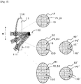
- FIG. 7 is a diagram illustrating the workings of the spectacle lens 10A.
- FIG. 7 shows a schematic cross-sectional view on line A-A' of FIG. 1 .
- FIG. 7 illustrates an exemplar in which part of dot portions, which are arranged uniformly in a lattice pattern, are moved only in the diametrical direction M to make the arrangement of the dot portions non-uniform.
- dot portions 15 are arranged in an isotropic arrangement pattern P1.
- dot portions 15 are arranged in a non-isotropic arrangement pattern.
- dot portions are arranged in an arrangement pattern P3 in which part of dot portions have been moved in the diametrical direction.
- dot portions are arranged in an arrangement pattern P2 in which more dot portions than in the second surrounding area B2 have been moved in the diametrical direction.
- the wearer views an object through the dot-portion group having dot portions each having a length equal to the length of each dot portion of the central area A in the diametrical direction M.
- the spectacle lens 10A enables preventing a direction-dependent difference in the contrast reduction effect in the surrounding area B.
- the spectacle lens 10A therefore enables to prevent causing an uncomfortable feeling to the wearer and also prevent possible reduction in the function of assisting the wearer in focusing in the surrounding area B.
- the dot-portion group D further includes a third dot-portion group D3 lying in a surrounding area B2 which is an intermediate area located between the central area A and a peripheral surrounding area B1.
- dot portions 15 are arranged in an arrangement pattern P3 in which the distance between dot portions 15 in the diametrical direction M of the lens body is intermediate between the corresponding distance between dot portions 15 in the first dot-portion group D1 and the corresponding distance between dot portions 15 in the second dot-portion group D2.
- the wearer of the spectacle lens By gradually varying the dot portion arrangement pattern in the diametrical direction M in at least three areas, the wearer of the spectacle lens hardly perceives the variation of arrangement pattern and little suffers from deterioration of visibility.
- the dot-portion group D includes, in the circumferential direction S, a plurality of arrangement patterns which differ in the arrangement of dot portions 15 in the diametrical direction M. Further, as in the arrangement pattern shown by the symbol L3 in FIG. 1 , dot portions are arranged randomly in the circumferential direction S in the surrounding area B. Accordingly, the wearer of the spectacle lens hardly perceives the variation of arrangement pattern also in the circumferential direction S and little suffers from deterioration of visibility.
- FIG. 8 shows diagrams illustrating, based on an autocorrelation method, an influence exerted on contrast by a protruding structure provided in a spectacle lens and having a protruding shape in a cross-section in the diametrical direction M.
- FIGS. 8(A) and 8(B) illustrate a protruding structure 15P having a rectangular shape in a cross-section in the diametrical direction.
- dot portions are moved in such a manner as to cancel out the elongation of light flux by cosa in a peripheral portion of the spectacle lens.
- This enables the spectacle lens to respond to the change of light flux on the spectacle lens, corresponding to light flux that enters an eye of the wearer through dot portions of the surrounding area.
- the contrast at a frequency F1 decreases in proportion to "the square of the area of the shaded region / the lateral width of the shaded region". As shown in FIG. 8(A) , the shaded region shown in FIG.
- FIGS. 8(C) and 8(D) are diagrams illustrating, based on the autocorrelation method, an influence exerted on contrast by a change in the position of a protruding structure 15M provided in a spectacle lens and having a trapezoidal shape in a cross-section in the diametrical direction M.
- the protruding structure 15M has, at the periphery, an inclined portion(s) 15Ma whose thickness decreases outwardly.
- the outermost position of the inclined portion 15Ma in the diametrical direction M of the lens body lies at a distance m0 from the corresponding outermost position of the protruding structure 15P.
- the contrast at a frequency F1 decreases in proportion to "the square of the area of the shaded region / the lateral width of the shaded region".
- the shaded region shown in FIG. 8(D) corresponds to the difference between the original position of the protruding structure 15M and the position of the protruding structure 15M, shown by the symbol 15Ma, after the protruding structure 15M is moved in the diametrical direction M by a distance m2.
- the present inventor based on this fact, has found that introduction of a shape, which makes the lateral width of the shaded region large, to a protruding structure enables preventing an excessive reduction in low-frequency contrast.
- the corresponding distances m1 and m2 are determined to be about 5.6% of the diameter of light flux on the spectacle lens in the contrast calculation direction.
- dot portions 15 of the surrounding area B at least at their peripheries in the diametrical direction M, have inclined portions.
- the second dot-portion group D2 includes inclined dot portions which each have, at the periphery, an inclined portion(s) whose thickness decreases outwardly in the diametrical direction M, and which each have a length which is longer than the corresponding length of each dot portion of the first dot-portion group in the diametrical direction of the lens body.
- FIG. 9 shows an A-A' cross-sectional view of a spectacle lens 10B according to the second embodiment of the present disclosure, and partially enlarged views thereof.
- a schematic plan view of the spectacle lens 10B is the same as FIG. 1 .
- dot portions (inclined dot portions) 15d1, 15d2 ... each having a trapezoidal shape in a cross-section in the diametrical direction M, are provided in the surrounding area B and are arranged in a pattern in which at least one of two adjacent inclined dot portions has been moved in the diametrical direction M to form a coupled dot portion 15D.
- Coupled dot portions 15D are formed by moving part of dot portions as in the first embodiment, or by forming inclined portions 15ds at the peripheries of dot portions as in the second embodiment.
- the other structure of the spectacle lens 10B is the same as the spectacle lens 10A shown in FIG. 2 .
- FIG. 10 shows diagrams illustrating exemplary configurations of a coupled dot portion 15D.
- a coupled dot portion 15D may have a configuration in which adjacent dot portions are in contact with each other at a contact point 20a, as shown in FIG. 10(B) , by moving part of dot portions, which are arranged with an equal spacing g1 in the diametrical direction M, in the diametrical direction M as shown by broken lines in FIG. 10(A) .
- a coupled dot portion 15D may have a configuration in which peripheral portions of adjacent dot portions overlap each other as shown by the symbol 20b.
- the distance between the periphery of the dot portion that has moved and the periphery of an adjacent dot portion that has not moved is increased to g2 which is larger than the original distance g1.
- FIG. 10(D) it is possible to use a dot-pair configuration in which adjacent dot portions are slightly spaced apart from each other (at a distance shown by the symbol g3 in FIG. 10(D) ). Such a configuration may also achieve the effect of preventing excessive reduction in low-frequency contrast and the effect of preventing stray light to a certain extent.
- the closest portions of adjacent dot portions are shown by the symbol 20c in FIG. 10(D) .
- the distance between the peripheries of dot portions in the diametrical direction M may be set to be, for example, about 0.56% of the diameter of light flux (about 0.022 mm) or, for example, about 0.015 to 0.030 mm as the shortest distance between dot portions that achieves the same effect as a coupled dot portion.
- the value may be changed depending on a spatial frequency of interest.
- a dot portion having a plan-view shape with an aspect ratio of less than 1 more specifically a shape which is elongated in the diametrical direction of the spectacle lens (such as an elliptical shape, a gourd shape, or a rectangular shape).
- the aspect ratio of a dot portion is defined as "length w in the circumferential direction S (corresponding to the short axis) / length d1 in the diametrical direction M (corresponding to the long axis)", and is less than 1.
- Apreferable aspect ratio of a dot portion, having a plan-view shape with an aspect ratio of less than 1 is about 0.45 to 0.99.
- the aspect ratio w/d1 (w is the maximum length in the circumferential direction S, and d1 is the length in the diametrical direction M) is less than 1, preferably about 0.45 to 0.99.
- the dot-portion pairs shown in FIGS. 10(B) through 10(D) and the dot portion having a plan-view shape with an aspect ratio of less than 1, shown in FIG. 10(E) are formed by providing an inclined portion(s) to the periphery of a dot portion in the diametrical direction M as described above.
- Such a dot portion or a dot-portion pair enables more efficiently preventing stray light in the surrounding area of the spectacle lens.
- An inclined dot portion may be formed, for example, by using a mold, or by superimposing of ejected dots by IJ printing.
- a dot portion having a plan-view shape with an aspect ratio of less than 1 may have an elliptical shape, a gourd shape, or a rectangular shape.
- a coupled dot portion may be formed by ejecting ink dots simultaneously or successively by IJ printing.
- the above-described dot-portion group D according to the first embodiment may be regarded as including dot portions having a plan-view shape with an aspect ratio of less than 1.
- FIG. 11 is a graph showing the influence of the diametrical length of an inclined side portion of a protruding structure on the diameter of light flux on the spectacle lens 10A.
- the graph is obtained by performing a simulation according to the below-described basic conditions of the MTF measurement.
- a shift amount of a dot portion, which is necessary to completely prevent variation of the contrast reduction property, is indicated by the curve (1) shown by the solid line in FIG. 11 .
- the necessary shift amount of a dot portion is indicated by the curve (2) shown by the broken line in FIG. 11 .
- FIG. 12 shows diagrams illustrating the workings of a protruding structure provided in a spectacle lens and having a trapezoidal shape in diametrical cross-section.
- dot portions are arranged in an arrangement pattern in which part of the dot portions have been moved, and coupled dot portions have been formed by providing an inclined portion at the periphery of each dot portion.
- FIG. 13 is a partially enlarged diametrical cross-sectional view showing the structure of layers of a spectacle lens 10A1.
- the spectacle lens 10A1 shown in FIG. 13 includes a spectacle lens substrate 11 (hereinafter also referred to simply as the "lens substrate"), and a hard coat layer 13, the above-described metal-containing layer 15b (20), an antireflective layer 17 and a water-repellent layer 19, disposed in this order on a first main surface of the lens substrate 11.
- the layers other than the metal-containing layer 15b will be described.
- the lens substrate 11 has a first main surface 111, a second main surface 112, and an edge surface (not shown).
- the lens substrate 11 may be made of a plastic material or an inorganic glass.
- the material of the substrate include a polyurethane material such as a polythiourethane resin or a polyurethane resin, an epithio material such as a polysulfide resin, a polycarbonate material, and a diethylene glycol bisallyl carbonate material.
- a colorless substrate is generally used as the lens substrate 11
- a colored substrate may also be used as long as the transparency is not impaired.
- the refractive index of the lens substrate 11 is, for example, not less than 1.50 and not more than 1.74.
- the lens substrate 11 may be either a finished lens or a semifinished lens.
- the lens substrate 11 may have any of a plane surface, a convex surface, a concave surface, etc.
- the eyeglass lens of the present disclosure may be any of a unifocal lens, a multifocal lens, a progressive power lens, etc.
- a progressive power lens in general, a near vision zone and a transition zone (intermediate zone) are included in a lower area, while a distance vision zone is included in an upper area.
- the hard coat layer 13 is formed, for example, by curing a curable composition comprising inorganic oxide particles and a silicon compound.
- the composition of the hard coat layer 13 is selected depending on the material of the lens substrate 11.
- the refractive index (nD) of the hard coat layer 13 is, for example, not less than 1.50 and not more than 1.74.
- the antireflective layer 17 is a film having a multi-layer structure consisting of laminated layers with different refractive indices and which prevents reflection of light through an interference effect.
- An example of the antireflective layer 17 is a multi-layer laminate of low-refractive index layers 17L and high-refractive index layers 17H.
- the refractive index of each low-refractive index layer 17L is, for example, 1.35 to 1.80 at a wavelength of 500 to 550 nm.
- the refractive index of each high-refractive index layer 17H is, for example, 1.90 to 2.60 at a wavelength of 500 to 550 nm.
- the low-refractive index layers 17L are made of, for example, silicon dioxide (SiO 2 ) having a refractive index of about 1.43 to 1.47.
- the high-refractive index layers 17H are made of a material having a higher refractive index than the low-refractive index layers 17L.
- a mixture of metal oxides selected from niobium oxide (Nb 2 O 5 ), tantalum oxide (Ta 2 O 5 ), titanium oxide (TiO 2 ), zirconium oxide (ZrO 2 ), yttrium oxide (Y 2 O 3 ) and aluminum oxide (Al 2 O 3 ), with an appropriate mixing ratio may be used as the material.
- the water-repellent layer 19 comprises, for example, an organosilicon compound containing a fluorine-substituted alkyl group.
- the water-repellent layer 19 has such a thickness as to perform an antireflective function together with the antireflective layer 17.
- FIG. 14 is a partially enlarged diametrical cross-sectional view showing the structure of layers on a spectacle lens 10A2.
- the second spectacle lens 10A2 has basically the same structure as the spectacle lens 10A1, and a plan view of the spectacle lens 10A2 is the same as the plan view of the spectacle lens 10A1, shown in FIG. 1 .
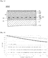
- the spectacle lens 10A2 includes a spectacle lens substrate 11 (hereinafter also referred to simply as the "lens substrate"), and a hard coat layer 13, a first inorganic layer 15c, a metal-containing layer 15b, a second inorganic layer 15e, an antireflective layer 17 and a water-repellent layer 19, disposed in this order on a first main surface of the lens substrate 11.
- a spectacle lens substrate 11 hereinafter also referred to simply as the "lens substrate”
- a hard coat layer 13 a first inorganic layer 15c, a metal-containing layer 15b, a second inorganic layer 15e, an antireflective layer 17 and a water-repellent layer 19, disposed in this order on a first main surface of the lens substrate 11.
- the first inorganic layer 15c is formed between the metal-containing layer 15b and the first main surface of the lens substrate 11, and is not formed in the openings.
- the provision of the first inorganic layer 15c can prevent peeling of the metal-containing layer 15b during the process of producing the spectacle lens 10A2.
- the second inorganic layer 15e is formed on the metal-containing layer 15b, and is not formed in the openings.
- the provision of the second inorganic layer 15e can prevent wear of the metal-containing layer 15b during the process of producing the spectacle lens 10A2, thereby preventing a decrease in the transmittance of the metal-containing layer 15b.
- the first inorganic layer 15c and the second inorganic layer 15e (hereinafter referred to simply as the "inorganic layer" which is a broader concept's term) can be formed of, for example, an inorganic oxide.
- the thickness of the inorganic layer is, for example, 1 to 100 nm, preferably 1 to 50 nm.
- Examples of the material of the inorganic layer include SiO 2 , Al 2 O 3 , Ta 2 O 5 , Nb 2 O 5 , ZrO 2 , TiO 2 , In 2 O 3 /SiO 2 (ITO), and CeO 2 .
- SiO 2 and Al 2 O 3 are preferred, and SiO 2 is more preferred.
- the inorganic layer can be formed by any known film-forming method.
- a vacuum vapor-deposition method for example, may be used.
- the same material as the material of the lowermost layer of the antireflective layer 17 can be used for the inorganic layer. This enables reducing the occurrence of a problem, such as interference, associated with the lowermost layer of the antireflective layer 17.
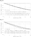
- FIG. 15 is a diagram showing the results of the simulation of the MTF characteristics of a spectacle lens having dot portions arranged non-uniformly.
- the contrast decreases with increase in spatial frequency both in a central area and in a surrounding area.
- the degrees of decrease in the contrast i.e. the degrees of the change with spatial frequency in these areas are very similar to each other.
- the dotted line indicates the characteristic of the spectacle lens having no dot portions.
- the solid line indicates the characteristics of the central area or the surrounding area, in the circumferential direction, of the spectacle lens having dot portions.
- the long broken line indicates the characteristics of the central area or the surrounding area, in the circumferential direction, of the spectacle lens having dot portions in the case where the diameter of light flux is 1.4 times larger.
- the dash-dot-dot-dash line indicates the characteristics of the central area or the surrounding area, in the circumferential direction, of the spectacle lens having dot portions in the case where the diameter of light flux is 2 times larger. The same holds true for the below-described FIGS. 16 through 18 .
- FIG. 16 is a diagram showing the simulation results of FIG. 15 , with the ordinate axis representing the degree of reduction of contrast compared to the spectacle lens having no dot portions.
- the degree of reduction of contrast is approximately equal for any of the locations in the spectacle lens.
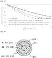
- FIG. 17 is a diagram showing the results of a simulation of the MTF characteristics of a spectacle lens having dot portions arranged non-uniformly in a pattern different from the case of FIG. 16 , with the ordinate axis representing the degree of reduction of contrast compared to a spectacle lens having no dot portions.
- the contrast reduction behaviors at the respective locations are very similar to each other, indicating that position-dependent variation in the contrast reduction effect is prevented.
- FIG. 18 is a diagram showing the results of a simulation of the MTF characteristics of a spectacle lens having dot portions arranged isotropically and uniformly, with the ordinate axis representing the degree of reduction of contrast compared to a spectacle lens having no dot portions.
- the degree of reduction of contrast varies among the locations in the spectacle lens. Further, the change of contrast with spatial frequency is large as compared to the characteristics shown in FIGS. 16 and 17 .
- dot portions are arranged randomly in the diametrical direction M and in the circumferential direction S in order to avoid causing an uncomfortable feeling to the wearer as much as possible.
- FIG. 19 is a schematic plan view of a spectacle lens 10C according to another embodiment of the present disclosure.
- the arrangement pattern of the first dot-portion group D1 of the central area A and the arrangement pattern of the third dot-portion group D3 of the surrounding area B2 located just outside the central area A are both a regular arrangement pattern P1.
- the arrangement pattern P2 of the second dot-portion group D2 of the surrounding area B1 located outside the surrounding area B2 is a pseudo-irregular pattern corresponding to an arrangement pattern in which dot portions located in a predetermined row and outer rows have been simply moved in the diametrical direction M to form coupled dot portions 15D.
- Such a pseudo-irregular pattern is easy to determine and form.
- the spectacle lens 10A includes the lens substrate 11, constituting a lens body, and the contrast adjustment section 30 provided on the lens substrate 11 and including the dot-portion group D in which dot portions 15 are arranged, and has an area in which dot portions 15 arranged in a non-uniform arrangement pattern P2.
- Non-uniform arrangement of dot portions 15 makes it possible to fully ensure the contrast reduction effect for the entire spectacle lens including the surrounding area B.
- the spectacle lens 10B includes the contrast adjustment section including a dot-portion group consisting of an arrangement of dot portions.
- the dot-portion group includes dot portions each having a plan-view shape with an aspect ratio of less than 1.
- the inclusion of dot portions, each having a plan-view shape with an aspect ratio of less than 1, in the dot-portion group enables preventing the generation of stray light while maintaining the contrast reduction effect.
- the spectacle lens of the present disclosure is applicable not only to daily-use visual correction glasses for near-sightedness, far-sightedness, astigmatism or presbyopia, protective glasses for protecting eyes, and magnifying glasses, but also to various other types of spectacle lenses, including an optical spectacle lens for a head mount display (HMD).
- HMD head mount display
Landscapes
- Physics & Mathematics (AREA)
- General Physics & Mathematics (AREA)
- Optics & Photonics (AREA)
- Health & Medical Sciences (AREA)
- Ophthalmology & Optometry (AREA)
- General Health & Medical Sciences (AREA)
- Chemical & Material Sciences (AREA)
- Inorganic Chemistry (AREA)
- Eyeglasses (AREA)
- Surface Treatment Of Optical Elements (AREA)
Abstract
Description
- The present disclosure relates to a spectacle lens.
- A spectacle lens has various layers covering a lens substrate, such as a hard coat layer for preventing scratching of the lens substrate, an antireflective layer for preventing reflection of light from the surface of the lens, and a water-repellent layer for preventing a water stain on the lens. Further, an optical member with a predetermined pattern formed by coating, and a lens having dots arranged in an isotropic pattern have recently been proposed (see, for example,
PTLs 1 and 2). -
- PTL 1:
JP 2008-55253 A - PTL 2:
WO 2016/125808 -
PTL 2 describes a pattern of dots arranged isotropically reduces the overall contrast of a lens, mainly in a low spatial frequency range, by a predetermined percentage, and thereby enables assisting the wearer in focusing. However, the lens having dots arranged in an isotropic pattern has the following problems. - At first, there is a problem, in a peripheral area where light flux enters obliquely, a difference exists in the degree of the contrast reduction effect between the diametrical direction and the circumferential direction of the lens. This sometimes causes an uncomfortable feeling to the user. The second problem is that stray light is likely to be generated by a dot pattern in a peripheral area of the lens.
- A first embodiment of the present disclosure relates to a spectacle lens which enables preventing the direction-dependent difference in the contrast reduction effect even in a peripheral area of the lens while having the contrast reduction effect mainly in a low spatial frequency range (e.g., a spatial frequency range of not more than 30 cpd (cycle per degree)).
- A second embodiment of the present disclosure relates to a spectacle lens which enables preventing the generation of stray light while having the contrast reduction effect.
- The spectacle lens according to the first embodiment of the present disclosure includes:
- a lens body; and
- a contrast adjustment section provided on or in the lens body and including a dot-portion group in which dot portions are arranged, wherein the arrangement of the dot portions are arranged is non-uniform.
- The spectacle lens according to the second embodiment of the present disclosure includes:
- a lens body; and
- a contrast adjustment section provided on or in the lens body and including a dot-portion group in which dot portions are arranged,
- wherein the dot-portion group includes dot portions each having an aspect ratio, which is the ratio of the length in the short-axis direction to the length in the long-axis direction in the plan-view shape, of less than 1.
- The first embodiment of the present disclosure provides a spectacle lens which enables ensuring the contrast reduction effect without depending on directions even in a peripheral area of the spectacle lens.
- The second embodiment of the present disclosure provides a spectacle lens which enables preventing the generation of stray light while having the contrast reduction effect.
-
-
FIG. 1 is a schematic plan view of aspectacle lens 10A according to the first embodiment of the present disclosure. -
FIG. 2 shows an A-A' cross-sectional view of thespectacle lens 10A and partially enlarged views thereof. -
FIG. 3 shows diagrams illustrating an arrangement ofdot portions 15. -
FIG. 4 is a schematic plan view of aspectacle lens 10X having dot portions arranged isotropically and uniformly over the entire surface. -
FIG. 5 is a diagram illustrating a problem that may occur in thespectacle lens 10X. -
FIG. 6 is a diagram illustrating another problem that may occur in thespectacle lens 10X. -
FIG. 7 is a diagram illustrating the workings of thespectacle lens 10A. -
FIG. 8 shows diagrams illustrating, based on an autocorrelation method, an influence exerted on contrast by a protruding structure provided in a spectacle lens and having a protruding shape in diametrical cross-section. -
FIG. 9 shows an A-A' cross-sectional view of aspectacle lens 10B according to the second embodiment of the present disclosure, and partially enlarged views thereof. -
FIG. 10 shows diagrams illustrating exemplary configurations of a coupleddot portion 15D. -
FIG. 11 is a graph showing the influence of the diametrical length of an inclined side portion of a protruding structure on the diameter of light flux on a spectacle lens. -
FIG. 12 shows diagrams illustrating the workings of a protruding structure provided in a spectacle lens and having a trapezoidal shape in diametrical cross-section. -
FIG. 13 is a partially enlarged diametrical cross-sectional view showing the structure of layers on a spectacle lens 10A1. -
FIG. 14 is a partially enlarged diametrical cross-sectional view showing the structure of layers on a spectacle lens 10A2. -
FIG. 15 is a diagram showing the results of a simulation of the Modulation Transfer Function (MTF) characteristics of a spectacle lens having dot portions arranged non-uniformly. -
FIG. 16 is a diagram showing the simulation results ofFIG. 15 , with the ordinate axis representing the degree of reduction of contrast compared to a spectacle lens having no dot portions. -
FIG. 17 is a diagram showing the results of a simulation of the MTF characteristics of a spectacle lens having dot portions arranged non-uniformly in a pattern different from the exemplarofFIG. 16 , with the ordinate axis representing the degree of reduction of contrast compared to a spectacle lens having no dot portions. -
FIG. 18 is a diagram showing the results of a simulation of the MTF characteristics of a spectacle lens having dot portions arranged isotropically and uniformly, with the ordinate axis representing the degree of reduction of contrast compared to a spectacle lens having no dot portions. -
FIG. 19 is a schematic plan view of aspectacle lens 10C according to another embodiment of the present disclosure. - Definitions of terms used throughout the specification are given below.
- "Arranged isotropically and uniformly" means a two-dimensional arrangement at regular intervals.
- "Dot portions are arranged at regular intervals" means an arrangement in which the distance from the center of any dot portion to the center of an adjacent dot portion is either the same or within a predetermined margin of error (e.g. within ± 10% of an average value).
- "Arrangement is non-uniform" indicates inclusion of an arrangement at irregular intervals, such as an arrangement in which the distance between the centers of some adjacent dot portions exceeds a predetermined margin of error, an arrangement in which the distance between the centers of adjacent dot portions varies with the diametrical position on a spectacle lens, or a random arrangement.
- In the below-described embodiments of the present disclosure, a spectacle lens includes, at least in a central area, dot portions arranged at regular intervals.
- "The diametrical direction of a spectacle lens" refers to a direction from the center of the lens toward the periphery along a main surface of the lens. "The diametrical direction of a spectacle lens" is sometimes referred to herein simply as "diametrical direction M".
- "The circumferential direction of a spectacle lens" refers to a direction along a main surface of the lens and intersecting the diametrical direction of the lens. "The circumferential direction of a spectacle lens" is sometimes referred to herein simply as "circumferential direction S".
- "Aspect ratio" refers to a ratio between two lengths in two orthogonal directions along a main surface of a lens. In particular, in the present disclosure, "the aspect ratio of a dot portion" refers to the ratio of the length of the dot portion in the short-axis direction to the length of the dot portion in the long-axis direction in the plan-view shape of the dot portion.
- Embodiments and examples of the present disclosure will be described below. The same symbols are used for the same or equivalent components or elements, and a description thereof may not be repeated. When reference is made to a number, an amount, etc. in the below-described embodiments and examples, the scope of the present disclosure is not necessarily limited to the number, the amount, etc. unless otherwise explicitly indicated. In the following embodiments, the below-described components or elements are each not necessarily essential unless otherwise explicitly indicated.
- The first embodiment of the present disclosure will now be described.
-
FIG. 1 is a schematic plan view of aspectacle lens 10A according to the first embodiment of the present disclosure. The structure of thespectacle lens 10A will be described with reference toFIG. 1 . - The
spectacle lens 10A includes a lens body, and a contrast adjustment section provided on the lens body. The lens body is composed of the below-describedlens substrate 11. - A number of
fine dot portions 15 are arranged on the entire surface of the lens body, and form a dot-portion group D. The dot-portion group D constitutes acontrast adjustment section 30 which functions to adjust the contrast of thespectacle lens 10A. - Each
dot portion 15 included in the dot-portion group D has a perfectly circular shape in a plan view. The arrangement pattern ofdot portions 15 in a central area A of thespectacle lens 10A differs from the one in a surrounding area B located outside the central area A. - In the dot-portion group (first dot-portion group) D1 of the central area A,
dot portions 15 are arranged in an isotropic arrangement pattern P1. Thus, the distances between the centers (arrangement pitch) of closest adjacent dot portions (closest dot portions) are the same, and the shortest distances between the peripheries of closest dot portions are the same. The structure of the dot-portion group D1, having thedot portions 15 arranged in the isotropic arrangement pattern P1, effectively reduces contrast in a low spatial frequency range (e.g., a spatial frequency range of not more than 30 cpd). If the arrangement pattern P1 has a degree of non-uniformity, a low-pass filter effect, which reduces contrast in a high spatial frequency range (e.g., a spatial frequency range of more than 30 cpd), may be caused as described, for example, inJapanese Patent Laid-Open Publication No. 2016-212333 - In the dot-portion group (second dot-portion group) D2 of the surrounding area B,
dot portions 15 are arranged in a non-uniform arrangement pattern P2. Thus, in the diametrical direction M, dotportions 15 are arranged uniformly in the central area A, whiledot portions 15 are arranged non-uniformly in the surrounding area B. The structure of the dot-portion group D2 also effectively reduces contrast in a low spatial frequency range. Thus, the non-uniformity of the arrangement pattern P2 is adjusted to such an extent that the low-pass filter effect is not be dominant. - In particular, in the surrounding area B, the distances between some
adjacent dots 15 in the diametrical direction M of the spectacle lens are long as compared to the central area A. Further, the surrounding area B has pairs of dot portions, coupled together, in the diametrical direction M. Such a dot-portion pair is hereinafter referred to as a coupleddot portion 15D. The length of a coupleddot portion 15D in the diametrical direction M is longer than the corresponding length of each of thedot portions 15 constituting the coupleddot portion 15D. - A more specific arrangement of the
dot portions 15 will be described in detail below under the heading "Workings of the Contrast Adjustment Section". - For the
dot portions 15 of the dot-portion group D2 of the surrounding area B, some adjacent dot portions are intentionally disposed farther apart in the diametrical direction M, some are closer to, and some are in contact with each other in order to achieve the below-described effect. The arrangement pattern P2 thus differs from arrangement patterns in which some dot portions, which should be arranged uniformly, are displaced or elongated in the circumferential direction e.g. due to an error upon the formation of the dot portions. - On the other hand, the dot-portion group D includes, in the circumferential direction S, a plurality of arrangements which differ in the arrangement of
dot portions 15 in the diametrical direction M, as shown by the symbols L1 and L2 inFIG. 1 . Thus, the first arrangement L1 and the second arrangement L2, which differ from each other in the arrangement pattern ofdot portions 15 in the diametrical direction M, are located at different positions in the circumferential direction S. - Compared to a spectacle lens having a dot-portion group consisting of dot portions arranged uniformly over the entire lens surface, the arrangement of the dot portions of the dot-portion group D may be regarded as non-uniform as a whole.
-
FIG. 2 shows a schematic A-A' cross-sectional view of thespectacle lens 10A and partially enlarged views thereof. As shown inFIG. 2 , thespectacle lens 10A includes a spectacle lens substrate 11 (hereinafter also referred to simply as the "lens substrate") which constitutes the lens body. Thelens substrate 11 has a firstmain surface 111 and a secondmain surface 112. Protrusions and recesses, constituting thedot portions 15, are formed on the firstmain surface 111. In the schematic cross-sectional view of theentire spectacle lens 10A inFIG. 2 , thedot portions 15 on the firstmain surface 111 are depicted in a simplified form to clearly illustrate the protruding/recessed structure. The same holds true for the below-describedFIGS. 5 through 7 , and9 . The structure and arrangement of thedot portions 15 of this embodiment will be described in more detail with reference to other drawings, etc. While other layers are provided on the firstmain surface 111 of thelens substrate 11, depiction of such layers is omitted fromFIG. 2 , etc. The structure of layers of the spectacle lens, including other layers, and the materials of the respective layers will be described later. - The
contrast adjustment section 30 of thespectacle lens 10A has a structure which performs the function of adjusting contrast to assist the wearer in focusing. Thecontrast adjustment section 30 has, for example, a structure which is provided on the firstmain surface 111 of thelens substrate 11 of thespectacle lens 10A and which produces a phase difference. - The
contrast adjustment section 30 may be formed as a layer on the lens substrate, or formed as a surface structure of the lens by using a mold having a processed portion corresponding to the surface structure, or formed by post-processing of the lens. - When the
contrast adjustment section 30 is formed as a layer, it may be formed on the lens substrate either directly or via another layer such as an adhesive layer. - The dot portions, included in the
contrast adjustment section 30, may each be a tangible object, or a space surrounded by a tangible object. - The material of the
contrast adjustment section 30 may have the same light permeability as or a different light permeability from the lens substrate. - The dot portions may be formed on the surface of the lens substrate or within the lens substrate.
- The
contrast adjustment section 30 includes a number of fine dot-shaped openings (recessed portions) that constitute thedot portions 15 of thespectacle lens 10A. In the central area A of thespectacle lens 10A, thedot portions 15 are arranged isotropically and uniformly. Isotropic arrangement at an equal pitch of the fine dot-shaped openings allows thecontrast adjustment section 30 to provide a contrast reduction effect, thereby assisting the wearer of thespectacle lens 10A in focusing. - The
contrast adjustment section 30 is composed of, for example, a metal-containinglayer 20. The metal contained in the metal-containinglayer 20 is, for example, at least one metal selected from the group consisting of Cr, Ta, Nb, Ti, Zr, Au, Ag, and Al, and preferably is Cr. The use of a metal-containing layer as thecontrast adjustment section 30 can also achieve the effect of preventing electrostatic charging of the spectacle lens. - The
contrast adjustment section 30 is obtainable by, for example, ink jet (IJ) printing. In this case, a dotted layer, which is to be finally peeled off, is first printed on the lens substrate by IJ printing, and then the print is covered with a metal-containing layer. Thereafter, the dotted print layer, together with the corresponding portion of the metal-containing layer, is peeled off the lens substrate. In this manner, dot-shaped openings can be formed in the metal-containing layer. - The dot portions may also be formed by a printing method other than IJ printing, or by vapor deposition or the like.
- When the dot portions are tangible objectsr, the dot portions can be formed directly on the lens substrate by printing the matter on the lens substrate e.g. by IJ printing.
- The
contrast adjustment section 30 includes the dot-portion group D in which dotportions 15 are arranged. - The dot-portion group D includes the first dot-portion group D1 lying in the central area A of the lens body, and the second dot-portion group D2 lying in the surrounding area B located outside the central area A. Compared to the first dot-portion group D1, (i) the distances between adjacent dot portions in the diametrical direction of the lens body are longer in the second dot-portion group D2.
- In the embodiment illustrated in
FIG. 1 , thedot portions 15 of the first dot-portion group D1 are arranged in a lattice pattern. - The arrangement of the dot portions of the second dot-portion group D2 corresponds to an arrangement in which dot
portions 15 at predetermined positions of the arrangement of thedot portions 15 of the first dot-portion group D 1 have been moved in the diametrical direction M of the lens body. - Thus, compared to the first dot-portion group D1, (ii) the lengths of
dot portions 15 in the diametrical direction of the lens body are longer in the second dot-portion group D2. -
FIG. 3 shows diagrams illustrating the arrangement ofdot portions 15. As shown in the enlarged view ofFIG. 3(A) , in the dot-portion group D1 of the central area A, the distance c1 between anydot portion 15 and the center of anadjacent dot portion 15 is, for example, not less than 0.1 mm, preferably not less than 0.2 mm, and more preferably not less than 0.3 mm, and is, for example, not more than 5.0 mm, preferably not more than 3.0 mm, and more preferably not more than 1.0 mm. - The shortest distance g1 between the peripheries of any
adjacent dot portions 15 is, for example, not less than 0.03 mm, preferably not less than 0.06 mm, and more preferably not less than 0.12 mm, and is, for example, not more than 1.6 mm, preferably not more than 1.0 mm, and more preferably not more than 0.3 mm. - The diameter r of each
dot portion 15 is, for example, not less than 0.01 mm, preferably not less than 0.05 mm, and more preferably not less than 0.1 mm, and is, for example, not more than 5.0 mm, preferably not more than 2.0 mm, more preferably not more than 1.0 mm, and even more preferably not more than 0.5 mm. - The ratio of distance c1 to diameter r (c1/r) is preferably more than 1.0, more preferably not less than 1.1, and even more preferably not less than 1.2, and is preferably not more than 2.0, more preferably not more than 1.8, and even more preferably not more than 1.5.
- The second dot-portion group D2 includes pairs of dot portions coupled together. Such a dot-portion pair forms a coupled
dot portion 15D whose length in the diametrical direction M of the lens body is longer than the corresponding length of each of thedot portions 15 constituting the dot-portion pair. -
FIG. 3(B) shows enlarged views of the arrangement L1 and the arrangement L2 shown inFIG. 1 . The arrangement L1 and the arrangement L2, which are located at different positions in the circumferential direction S, each include coupleddot portions 15D which may be regarded as being formed by moving somedot portions 15 in the diametrical direction M. Therefore, the distance g2 between a coupleddot portion 15D and an adjacent dot portion in the diametrical direction M is longer than the corresponding distance g1 in the first dot-portion group D1 of the central area A. - The length by which a dot portion is to be moved in the diametrical direction M in order to form a coupled
dot portion 15D is preferably set in consideration of the fact that when viewed from the wearer of the spectacle lens, light flux on the spectacle lens, which is entering the lens, is elongated in the diametrical direction M in the surrounding area B. In particular, the movement length should preferably be set so that the above distance g2 optically cancels out the elongation of light flux, and the wearer can perceive the same contrast as in the central area A. The movement distance may be, for example, about 0.02 to 4.5 mm. The length d1 of a coupleddot portion 15D in the diametrical direction M will be described below with reference toFIG. 10 . - The workings of the contrast adjustment section of the spectacle lens according to this embodiment will now be described in comparison with a spectacle lens having dot portions arranged isotropically and uniformly over the entire lens surface. In
FIGS. 3 through 7 , in order to facilitate easier understanding, the length, the height, etc. of each dot portion are exaggerated, and the number of dot portions is depicted as smaller than the one in reality. - In the following description, dot portions will sometimes be described or illustrated as if they were tangible objects. When a fine structure which may provide a phase difference is provided on the lens body, whether the dot potions are spatial or tangible, the wearer perceives them equivalent, and no significant problem will arise if dot portions are described as if they were tangible objects. Therefore, dot portions will be described and illustrated in such a manner to facilitate the description and illustration.
-
FIG. 4 is a schematic plan view of aspectacle lens 10X having dot portions arranged isotropically and uniformly over the entire surface. In thespectacle lens 10X, the arrangement pattern is substantially the same at any position on the first main surface of thelens substrate 11. -
FIG. 5 is a diagram illustrating a problem that may occur in thespectacle lens 10X.FIG. 5 shows a schematic cross-sectional view on line B-B' ofFIG. 4 and partially enlarged views thereof. - As shown in
FIG. 5 , assuming light coming from aneye 100 of the wearer of thespectacle lens 10X and entering the lens at an incident angle α with respect to a line segment connecting theeye 100 and the center of thespectacle lens 10X, the diameter of light flux on the spectacle lens is elongated by 1/cosa in the diametrical direction M of the spectacle lens. - This is equivalent to the fact that the length of each dot portion and the arrangement pitch are multiplied by cosa in the diametrical direction M of the spectacle lens, as shown in the lower left-side diagram of
FIG. 5 . Thus, as shown by the symbols B', P1', D2' and 15' in the lower right-side diagram ofFIG. 5 , the dot portions as perceived by the wearer are compacted in the size of each dot portion in the diametrical direction M and in the distance between adjacent dot portions as compared to the central area A. - Accordingly, the closer to a peripheral end portion in the diametrical direction M of the spectacle lens, the excessively lower the contrast of low-frequency components of incident light, while the contrast of high-frequency components of incident light is not reduced significantly. Thus, in the diametrical direction M of the spectacle lens, the contrast reduction effect varies with position on the spectral lens, making it impossible to obtain desired contrast reduction characteristics.
- There is no such variation in the contrast reduction effect in the circumferential direction S of the spectacle lens. The contrast reduction characteristics thus differ between the circumferential direction S and the diametrical direction M. This may cause an uncomfortable feeling to the wearer as if astigmatism had occurred.
-
FIG. 6 is a diagram illustrating another problem that may occur in thespectacle lens 10X.FIG. 6 is a schematic cross-sectional view on line B-B', showing light entering thespectacle lens 10X from the outside. - As shown in
FIG. 6 , in the surrounding area B of thespectacle lens 10X, thedot portions 15 of thecontrast adjustment section 30 are inclined, following the curve of thespectacle lens 10X, and therefore the inclination of the wall surface of eachdot portion 15 is relatively large. Consequently, as schematically shown inFIG. 6 , stray light resulting from the wall surface of such adot portion 15 is likely to be generated, such as due to reflection of light, emitted by alight source 200, from the wall surface of thedot portion 15. -
FIG. 7 is a diagram illustrating the workings of thespectacle lens 10A.FIG. 7 shows a schematic cross-sectional view on line A-A' ofFIG. 1 . To facilitate illustration and understanding,FIG. 7 illustrates an exemplar in which part of dot portions, which are arranged uniformly in a lattice pattern, are moved only in the diametrical direction M to make the arrangement of the dot portions non-uniform. - As shown in
FIG. 7 , in the central area A,dot portions 15 are arranged in an isotropic arrangement pattern P1. In the surrounding area B,dot portions 15 are arranged in a non-isotropic arrangement pattern. - In particular, in a central area A-side second surrounding area B2, dot portions are arranged in an arrangement pattern P3 in which part of dot portions have been moved in the diametrical direction. In a first surrounding area B1 located outside the second surrounding area B2, dot portions are arranged in an arrangement pattern P2 in which more dot portions than in the second surrounding area B2 have been moved in the diametrical direction.
- When the wearer of the spectacle lens views an object through the surrounding area B, light flux that enters an eye of the wearer is elongated on the spectacle lens in the diametrical direction. However, since the dot portions in the surrounding area B are arranged in an arrangement pattern in which some dot portions have been moved in the diametrical direction M as described above, the wearer views the object through a pattern of dot portions in which the arrangement pitch in the diametrical direction M is equal to the arrangement pitch in the central area A, as shown with the symbols B2', P2', 15' and 15D' in the right-side diagrams of
FIG. 7 . Further, since coupling of dot portions is equivalent to elongation of either one of the dot portions in the diametrical direction M, the wearer views an object through the dot-portion group having dot portions each having a length equal to the length of each dot portion of the central area A in the diametrical direction M. - Thus, the
spectacle lens 10A enables preventing a direction-dependent difference in the contrast reduction effect in the surrounding area B. Thespectacle lens 10A therefore enables to prevent causing an uncomfortable feeling to the wearer and also prevent possible reduction in the function of assisting the wearer in focusing in the surrounding area B. - As with the embodiment illustrated in
FIG. 7 , in the embodiment illustrate inFIGS. 1 through 3 , the dot-portion group D further includes a third dot-portion group D3 lying in a surrounding area B2 which is an intermediate area located between the central area A and a peripheral surrounding area B1. - In the third dot-portion group D3,
dot portions 15 are arranged in an arrangement pattern P3 in which the distance betweendot portions 15 in the diametrical direction M of the lens body is intermediate between the corresponding distance betweendot portions 15 in the first dot-portion group D1 and the corresponding distance betweendot portions 15 in the second dot-portion group D2. - By gradually varying the dot portion arrangement pattern in the diametrical direction M in at least three areas, the wearer of the spectacle lens hardly perceives the variation of arrangement pattern and little suffers from deterioration of visibility.
- On the other hand, the dot-portion group D includes, in the circumferential direction S, a plurality of arrangement patterns which differ in the arrangement of
dot portions 15 in the diametrical direction M. Further, as in the arrangement pattern shown by the symbol L3 inFIG. 1 , dot portions are arranged randomly in the circumferential direction S in the surrounding area B. Accordingly, the wearer of the spectacle lens hardly perceives the variation of arrangement pattern also in the circumferential direction S and little suffers from deterioration of visibility. - The second embodiment of the present disclosure will now be described. Prior to the description of details of the second embodiment, the influence of a protruding structure, provided on a lens body, on contrast will be described first.
-
FIG. 8 shows diagrams illustrating, based on an autocorrelation method, an influence exerted on contrast by a protruding structure provided in a spectacle lens and having a protruding shape in a cross-section in the diametrical direction M. -
FIGS. 8(A) and 8(B) illustrate a protrudingstructure 15P having a rectangular shape in a cross-section in the diametrical direction. - In the first embodiment described above, dot portions are moved in such a manner as to cancel out the elongation of light flux by cosa in a peripheral portion of the spectacle lens. This enables the spectacle lens to respond to the change of light flux on the spectacle lens, corresponding to light flux that enters an eye of the wearer through dot portions of the surrounding area. According to the concept of an autocorrelation method, which is one of MTF calculation techniques, the contrast at a frequency F1 decreases in proportion to "the square of the area of the shaded region / the lateral width of the shaded region". As shown in
FIG. 8(A) , the shaded region shown inFIG. 8(B) corresponds to the difference between the original position of the protrudingstructure 15P and the position of the protrudingstructure 15P, shown by the symbol 15a, after the protrudingstructure 15P is moved in the diametrical direction M by a distance L1 corresponding to the MTF calculation frequency F1. - The consideration made above with reference to
FIGS. 8(A) and 8(B) holds true for a protruding structure provided in a surrounding area of a spectral lens and having a trapezoidal shape in a cross-section in the diametrical direction M.FIGS. 8(C) and 8(D) are diagrams illustrating, based on the autocorrelation method, an influence exerted on contrast by a change in the position of a protrudingstructure 15M provided in a spectacle lens and having a trapezoidal shape in a cross-section in the diametrical direction M. - The protruding
structure 15M has, at the periphery, an inclined portion(s) 15Ma whose thickness decreases outwardly. The outermost position of the inclined portion 15Ma in the diametrical direction M of the lens body lies at a distance m0 from the corresponding outermost position of the protrudingstructure 15P. - Also in this case, the contrast at a frequency F1 decreases in proportion to "the square of the area of the shaded region / the lateral width of the shaded region". As shown in
FIG. 8(C) , the shaded region shown inFIG. 8(D) corresponds to the difference between the original position of the protrudingstructure 15M and the position of the protrudingstructure 15M, shown by the symbol 15Ma, after the protrudingstructure 15M is moved in the diametrical direction M by a distance m2. The present inventor, based on this fact, has found that introduction of a shape, which makes the lateral width of the shaded region large, to a protruding structure enables preventing an excessive reduction in low-frequency contrast. - For example, assuming a pupil diameter of 4 mm, a wavelength of 555 nm, and a frequency F1 of 7 cpd (cycle per degree), and taking a cutoff frequency into consideration, the corresponding distances m1 and m2 are determined to be about 5.6% of the diameter of light flux on the spectacle lens in the contrast calculation direction.
- In the second embodiment, therefore, dot
portions 15 of the surrounding area B, at least at their peripheries in the diametrical direction M, have inclined portions. Thus, the second dot-portion group D2 includes inclined dot portions which each have, at the periphery, an inclined portion(s) whose thickness decreases outwardly in the diametrical direction M, and which each have a length which is longer than the corresponding length of each dot portion of the first dot-portion group in the diametrical direction of the lens body. -
FIG. 9 shows an A-A' cross-sectional view of aspectacle lens 10B according to the second embodiment of the present disclosure, and partially enlarged views thereof. A schematic plan view of thespectacle lens 10B is the same asFIG. 1 . - As shown in
FIG. 9 , dot portions (inclined dot portions) 15d1, 15d2 ..., each having a trapezoidal shape in a cross-section in the diametrical direction M, are provided in the surrounding area B and are arranged in a pattern in which at least one of two adjacent inclined dot portions has been moved in the diametrical direction M to form a coupleddot portion 15D. - Coupled
dot portions 15D are formed by moving part of dot portions as in the first embodiment, or by forming inclined portions 15ds at the peripheries of dot portions as in the second embodiment. The other structure of thespectacle lens 10B is the same as thespectacle lens 10A shown inFIG. 2 . -
FIG. 10 shows diagrams illustrating exemplary configurations of a coupleddot portion 15D. A coupleddot portion 15D may have a configuration in which adjacent dot portions are in contact with each other at a contact point 20a, as shown inFIG. 10(B) , by moving part of dot portions, which are arranged with an equal spacing g1 in the diametrical direction M, in the diametrical direction M as shown by broken lines inFIG. 10(A) . As shown inFIG. 10(C) , a coupleddot portion 15D may have a configuration in which peripheral portions of adjacent dot portions overlap each other as shown by thesymbol 20b. By moving a dot portion in the diametrical direction M, the distance between the periphery of the dot portion that has moved and the periphery of an adjacent dot portion that has not moved is increased to g2 which is larger than the original distance g1. - When adjacent dot portions are made to contact or overlap each other to obtain a coupled
dot portion 15D, the opposing wall surfaces of the dot portions either diminish or disappear. This contributes to achieving the effect of preventing stray light. - As shown in
FIG. 10(D) , it is possible to use a dot-pair configuration in which adjacent dot portions are slightly spaced apart from each other (at a distance shown by the symbol g3 inFIG. 10(D) ). Such a configuration may also achieve the effect of preventing excessive reduction in low-frequency contrast and the effect of preventing stray light to a certain extent. The closest portions of adjacent dot portions are shown by thesymbol 20c inFIG. 10(D) . The distance between the peripheries of dot portions in the diametrical direction M may be set to be, for example, about 0.56% of the diameter of light flux (about 0.022 mm) or, for example, about 0.015 to 0.030 mm as the shortest distance between dot portions that achieves the same effect as a coupled dot portion. The value may be changed depending on a spatial frequency of interest. - As shown in
FIG. 10(E) , it is also possible to use a dot portion having a plan-view shape with an aspect ratio of less than 1, more specifically a shape which is elongated in the diametrical direction of the spectacle lens (such as an elliptical shape, a gourd shape, or a rectangular shape). In this case, the aspect ratio of a dot portion is defined as "length w in the circumferential direction S (corresponding to the short axis) / length d1 in the diametrical direction M (corresponding to the long axis)", and is less than 1. Apreferable aspect ratio of a dot portion, having a plan-view shape with an aspect ratio of less than 1, is about 0.45 to 0.99. Also for a coupleddot portion 15D as shown inFIG. 10(A) or 10(B) , the aspect ratio w/d1 (w is the maximum length in the circumferential direction S, and d1 is the length in the diametrical direction M) is less than 1, preferably about 0.45 to 0.99. - In one embodiment, the dot-portion pairs shown in
FIGS. 10(B) through 10(D) and the dot portion having a plan-view shape with an aspect ratio of less than 1, shown inFIG. 10(E) are formed by providing an inclined portion(s) to the periphery of a dot portion in the diametrical direction M as described above. Such a dot portion or a dot-portion pair enables more efficiently preventing stray light in the surrounding area of the spectacle lens. - An inclined dot portion may be formed, for example, by using a mold, or by superimposing of ejected dots by IJ printing.
- A dot portion having a plan-view shape with an aspect ratio of less than 1 may have an elliptical shape, a gourd shape, or a rectangular shape. A coupled dot portion may be formed by ejecting ink dots simultaneously or successively by IJ printing.
- The above-described dot-portion group D according to the first embodiment may be regarded as including dot portions having a plan-view shape with an aspect ratio of less than 1.
-
FIG. 11 is a graph showing the influence of the diametrical length of an inclined side portion of a protruding structure on the diameter of light flux on thespectacle lens 10A. The graph is obtained by performing a simulation according to the below-described basic conditions of the MTF measurement. - A shift amount of a dot portion, which is necessary to completely prevent variation of the contrast reduction property, is indicated by the curve (1) shown by the solid line in
FIG. 11 . - In the case where the variation of the contrast reduction property is halved as compared to the case of no provision of a contrast adjustment section from the viewpoint of a balance between the contrast adjustment function and the ease of the formation of a contrast adjustment section, the necessary shift amount of a dot portion is indicated by the curve (2) shown by the broken line in
FIG. 11 . - As apparent from
FIG. 11 , in the case where a necessary variation of the contrast reduction property is about halved, the amount of movement of each dot portion or the percentage of dot portions to be moved becomes small. Thus, the percentage of coupled dot portions or dot portions having a shape which is elongated in the diametrical direction is reducible. -
FIG. 12 shows diagrams illustrating the workings of a protruding structure provided in a spectacle lens and having a trapezoidal shape in diametrical cross-section. - As shown in
FIG. 12(A) , in the case of a protrudingstructure 15P having no peripheral inclined portion and having a rectangular shape in a cress-section in the diametrical direction, light is likely to be reflected from the wall surface of the dot portion in a surrounding area of the spectacle lens, whereby stray light is likely to be generated. - On the other hand, as shown in
FIG. 12(B) , in the case of a protrudingstructure 15M having an inclined portion 15Ma at the periphery of the dot portion in the diametrical direction M, light is unlikely to be reflected from the wall surface of the dot portion even in a surrounding area of the spectacle lens. Thus, light rays may be prevented from becoming stray light. - In the above-described second embodiment, in the surrounding area B, dot portions are arranged in an arrangement pattern in which part of the dot portions have been moved, and coupled dot portions have been formed by providing an inclined portion at the periphery of each dot portion. This makes it possible to fully ensure the contrast reduction effect for the entire spectacle lens including the surrounding area B, and to prevent the generation of stray light.
- However, in a spectacle lens for use in an application for which a reduction in contrast does not matter much, it is possible to arrange dot portions isotropically over the entire spectacle lens, and to provide a peripheral inclined portion to dot portions only in a surrounding area to prevent stray light.
- Details of the structure of layers of a spectacle lens will now be described.
-
FIG. 13 is a partially enlarged diametrical cross-sectional view showing the structure of layers of a spectacle lens 10A1. - The spectacle lens 10A1 shown in
FIG. 13 includes a spectacle lens substrate 11 (hereinafter also referred to simply as the "lens substrate"), and ahard coat layer 13, the above-described metal-containinglayer 15b (20), anantireflective layer 17 and a water-repellent layer 19, disposed in this order on a first main surface of thelens substrate 11. The layers other than the metal-containinglayer 15b will be described. - As shown in
FIG. 13 , thelens substrate 11 has a firstmain surface 111, a secondmain surface 112, and an edge surface (not shown). - The
lens substrate 11 may be made of a plastic material or an inorganic glass. Examples of the material of the substrate include a polyurethane material such as a polythiourethane resin or a polyurethane resin, an epithio material such as a polysulfide resin, a polycarbonate material, and a diethylene glycol bisallyl carbonate material. - While a colorless substrate is generally used as the
lens substrate 11, a colored substrate may also be used as long as the transparency is not impaired. - The refractive index of the
lens substrate 11 is, for example, not less than 1.50 and not more than 1.74. - The
lens substrate 11 may be either a finished lens or a semifinished lens. - There is no particular limitation on the surface shape of the
lens substrate 11; thelens substrate 11 may have any of a plane surface, a convex surface, a concave surface, etc. - The eyeglass lens of the present disclosure may be any of a unifocal lens, a multifocal lens, a progressive power lens, etc. In the case of a progressive power lens, in general, a near vision zone and a transition zone (intermediate zone) are included in a lower area, while a distance vision zone is included in an upper area.
- The
hard coat layer 13 is formed, for example, by curing a curable composition comprising inorganic oxide particles and a silicon compound. The composition of thehard coat layer 13 is selected depending on the material of thelens substrate 11. The refractive index (nD) of thehard coat layer 13 is, for example, not less than 1.50 and not more than 1.74. - The
antireflective layer 17 is a film having a multi-layer structure consisting of laminated layers with different refractive indices and which prevents reflection of light through an interference effect. An example of theantireflective layer 17 is a multi-layer laminate of low-refractive index layers 17L and high-refractive index layers 17H. The refractive index of each low-refractive index layer 17L is, for example, 1.35 to 1.80 at a wavelength of 500 to 550 nm. The refractive index of each high-refractive index layer 17H is, for example, 1.90 to 2.60 at a wavelength of 500 to 550 nm. - The low-refractive index layers 17L are made of, for example, silicon dioxide (SiO2) having a refractive index of about 1.43 to 1.47. The high-refractive index layers 17H are made of a material having a higher refractive index than the low-refractive index layers 17L. For example, a mixture of metal oxides, selected from niobium oxide (Nb2O5), tantalum oxide (Ta2O5), titanium oxide (TiO2), zirconium oxide (ZrO2), yttrium oxide (Y2O3) and aluminum oxide (Al2O3), with an appropriate mixing ratio may be used as the material.
- The water-
repellent layer 19 comprises, for example, an organosilicon compound containing a fluorine-substituted alkyl group. The water-repellent layer 19 has such a thickness as to perform an antireflective function together with theantireflective layer 17. -
FIG. 14 is a partially enlarged diametrical cross-sectional view showing the structure of layers on a spectacle lens 10A2. - The second spectacle lens 10A2 has basically the same structure as the spectacle lens 10A1, and a plan view of the spectacle lens 10A2 is the same as the plan view of the spectacle lens 10A1, shown in
FIG. 1 . - As shown in
FIG. 14 , the spectacle lens 10A2 includes a spectacle lens substrate 11 (hereinafter also referred to simply as the "lens substrate"), and ahard coat layer 13, a firstinorganic layer 15c, a metal-containinglayer 15b, a secondinorganic layer 15e, anantireflective layer 17 and a water-repellent layer 19, disposed in this order on a first main surface of thelens substrate 11. - The first
inorganic layer 15c is formed between the metal-containinglayer 15b and the first main surface of thelens substrate 11, and is not formed in the openings. The provision of the firstinorganic layer 15c can prevent peeling of the metal-containinglayer 15b during the process of producing the spectacle lens 10A2. - The second
inorganic layer 15e is formed on the metal-containinglayer 15b, and is not formed in the openings. The provision of the secondinorganic layer 15e can prevent wear of the metal-containinglayer 15b during the process of producing the spectacle lens 10A2, thereby preventing a decrease in the transmittance of the metal-containinglayer 15b. - The first
inorganic layer 15c and the secondinorganic layer 15e (hereinafter referred to simply as the "inorganic layer" which is a broader concept's term) can be formed of, for example, an inorganic oxide. - The thickness of the inorganic layer is, for example, 1 to 100 nm, preferably 1 to 50 nm.
- Examples of the material of the inorganic layer include SiO2, Al2O3, Ta2O5, Nb2O5, ZrO2, TiO2, In2O3/SiO2 (ITO), and CeO2.
- Among them, SiO2 and Al2O3 are preferred, and SiO2 is more preferred.
- The inorganic layer can be formed by any known film-forming method. A vacuum vapor-deposition method, for example, may be used.
- The same material as the material of the lowermost layer of the
antireflective layer 17 can be used for the inorganic layer. This enables reducing the occurrence of a problem, such as interference, associated with the lowermost layer of theantireflective layer 17. - Using a model having the same structure as the spectacle lens of the above-described embodiment, a simulation was conducted to determine the influence of a dot-portion group, constituting a contrast adjustment section, on the contrast of a spectacle lens.
- The basic conditions of the simulation are as follows.
- Pitch of dot portions: 0.500 mm
- Diameter of each dot portion: 0.350 mm
- Spacing between the peripheries of dot portions: 0.150 mm
- Phase loading: 0.15 λ
- Transmittance: 100%
- Wavelength: 555 nm
- Assumed pupil diameter: 4 mm
-
FIG. 15 is a diagram showing the results of the simulation of the MTF characteristics of a spectacle lens having dot portions arranged non-uniformly. - The following conditions were set for a pattern of non-uniform arrangement of the dot portions.
- [1A] At a location where the diameter of light flux doubles in the diametrical direction, every dot portion is in contact with an adjacent dot portion in the diametrical direction (the distance between closest dot portions is 0 mm); that is, every dot portion constitutes a coupled dot portion. The dot portions do not have any peripheral inclined portion, i.e., do not include inclined dot portions.
- [2A] At a location where the diameter of light flux reaches 1.4 times in the diametrical direction, the positions of dot portions are set randomly such that the average distance between closest dot portions in the diametrical direction is 0.090 mm. 16% of the dot portions are coupled dot portions each consisting of two dot portions in contact with each other in the diametrical direction. The dot portions have a peripheral inclined portion, i.e., include inclined dot portions. The average length of the inclined portion in the diametrical direction is 0.043 mm.
- As can be seen in
FIG. 15 , compared to a spectacle lens having no dot portions as a control, the contrast decreases with increase in spatial frequency both in a central area and in a surrounding area. The degrees of decrease in the contrast, i.e. the degrees of the change with spatial frequency in these areas are very similar to each other. InFIG. 15 , the dotted line indicates the characteristic of the spectacle lens having no dot portions. The solid line indicates the characteristics of the central area or the surrounding area, in the circumferential direction, of the spectacle lens having dot portions. The long broken line indicates the characteristics of the central area or the surrounding area, in the circumferential direction, of the spectacle lens having dot portions in the case where the diameter of light flux is 1.4 times larger. The dash-dot-dot-dash line indicates the characteristics of the central area or the surrounding area, in the circumferential direction, of the spectacle lens having dot portions in the case where the diameter of light flux is 2 times larger. The same holds true for the below-describedFIGS. 16 through 18 . -
FIG. 16 is a diagram showing the simulation results ofFIG. 15 , with the ordinate axis representing the degree of reduction of contrast compared to the spectacle lens having no dot portions. - As apparent from
FIG. 16 , while the differences between the respective curves are enhanced by taking the degree of reduction of contrast as the ordinate, the degree of reduction of contrast is approximately equal for any of the locations in the spectacle lens. -
FIG. 17 is a diagram showing the results of a simulation of the MTF characteristics of a spectacle lens having dot portions arranged non-uniformly in a pattern different from the case ofFIG. 16 , with the ordinate axis representing the degree of reduction of contrast compared to a spectacle lens having no dot portions. - The following conditions [1B] to [3B] were set for a pattern of non-uniform arrangement of the dot portions.
- [1B] The proportion of coupled dot portions was set to be "light-flux diameter magnification factor - 1".
- [2B] At a location where the diameter of light flux is 2 times larger in the diametrical direction, every dot portion is in contact with an adjacent dot portion in the diametrical direction (the distance between closest dot portions is 0 mm); that is, every dot portion constitutes a coupled dot portion. The dot portions do not have any peripheral inclined portion, i.e., do not include inclined dot portions.
- [3B] At a location where the diameter of light flux is 1.4 times larger in the diametrical direction, the positions of dot portions are set randomly such that the average distance between closest dot portions in the diametrical direction is 0.090 mm. 40% of the dot portions are coupled dot portions each consisting of two dot portions in contact with each other in the diametrical direction. The dot portions do not have any peripheral inclined portion, i.e., do not include inclined dot portions.
- As apparent from
FIG. 17 , the contrast reduction behaviors at the respective locations are very similar to each other, indicating that position-dependent variation in the contrast reduction effect is prevented. -
FIG. 18 is a diagram showing the results of a simulation of the MTF characteristics of a spectacle lens having dot portions arranged isotropically and uniformly, with the ordinate axis representing the degree of reduction of contrast compared to a spectacle lens having no dot portions. - As apparent from
FIG. 18 , the degree of reduction of contrast varies among the locations in the spectacle lens. Further, the change of contrast with spatial frequency is large as compared to the characteristics shown inFIGS. 16 and 17 . - In the arrangement patterns P2 and P3 shown in
FIG. 1 , dot portions are arranged randomly in the diametrical direction M and in the circumferential direction S in order to avoid causing an uncomfortable feeling to the wearer as much as possible. However, it is also possible to form a pseudo-irregular pattern by moving dot portions more regularly. -
FIG. 19 is a schematic plan view of aspectacle lens 10C according to another embodiment of the present disclosure. - As shown in
FIG. 19 , in thespectacle lens 10C, the arrangement pattern of the first dot-portion group D1 of the central area A and the arrangement pattern of the third dot-portion group D3 of the surrounding area B2 located just outside the central area A are both a regular arrangement pattern P1. - The arrangement pattern P2 of the second dot-portion group D2 of the surrounding area B1 located outside the surrounding area B2 is a pseudo-irregular pattern corresponding to an arrangement pattern in which dot portions located in a predetermined row and outer rows have been simply moved in the diametrical direction M to form coupled
dot portions 15D. Such a pseudo-irregular pattern is easy to determine and form. - The above-described examples and preferred ranges of the respective components and their contents and physical properties may be arbitrarily combined.
- Further, by adjusting a composition as described in the working examples to make it relevant to a composition as described in the detailed description of the invention, the disclosed embodiment can be carried out as in the working examples for the entire scope of the claimed composition.
- Lastly, the embodiment of the present disclosure will be summarized with reference to the drawings.
- As shown in
FIGS. 1, 2 and6 , thespectacle lens 10A according to an embodiment of the present disclosure includes thelens substrate 11, constituting a lens body, and thecontrast adjustment section 30 provided on thelens substrate 11 and including the dot-portion group D in which dotportions 15 are arranged, and has an area in which dotportions 15 arranged in a non-uniform arrangement pattern P2. Non-uniform arrangement ofdot portions 15 makes it possible to fully ensure the contrast reduction effect for the entire spectacle lens including the surrounding area B. - As shown in
FIGS. 1 ,6 ,9 and10 , thespectacle lens 10B according to another embodiment of the present disclosure includes the contrast adjustment section including a dot-portion group consisting of an arrangement of dot portions. The dot-portion group includes dot portions each having a plan-view shape with an aspect ratio of less than 1. The inclusion of dot portions, each having a plan-view shape with an aspect ratio of less than 1, in the dot-portion group enables preventing the generation of stray light while maintaining the contrast reduction effect. - The spectacle lens of the present disclosure is applicable not only to daily-use visual correction glasses for near-sightedness, far-sightedness, astigmatism or presbyopia, protective glasses for protecting eyes, and magnifying glasses, but also to various other types of spectacle lenses, including an optical spectacle lens for a head mount display (HMD).
- The embodiments disclosed herein should be construed merely exemplary and not limitative in every way. It is intended that the scope of the present invention is defined not by the description given above but by the claims, and includes changes and modifications made within the meaning and scope of the claims and their equivalents.
-
- 10A, 10A1, 10A2, 10B, 10C: spectacle lens
- 11: lens substrate (lens body)
- 13: hard coat layer
- 15: dot portion
- 15b, 20: metal-containing layer
- 15D: coupled dot portion
- 15d1, 15d2: inclined dot portion
- 17: antireflective layer
- 17L: low-refractive index layer
- 17H: high-refractive index layer
- 19: water-repellent layer
- 30: contrast adjustment section
- A: central area
- B, B1, B2: surrounding area
- D1: first dot-portion group
- D2: second dot-portion group
- D3: third dot-portion group
- P1, P2, P3: arrangement pattern
- L1: first arrangement
- L2: second arrangement
- M: diametrical direction
- S: circumferential direction
- g1, g2. g3: distance between the peripheries of dot portions in the diametrical direction M
- d1: length of a dot portion in the diametrical direction M
- w: length of a dot portion in the circumferential direction S
- r: diameter of a dot portion
Claims (13)
- A spectacle lens comprising:a lens body; anda contrast adjustment section provided on or in the lens body and comprising a dot-portion group in which dot portions are arranged,wherein the arrangement of the dot portions is non-uniform.
- The spectacle lens according to claim 1, wherein the dot-portion group comprises a first dot-portion group lying in a central area of the lens body, and a second dot-portion group lying in a surrounding area located outside the central area, and wherein compared to the first dot-portion group, (i) the distances between adjacent dot portions in the diametrical direction of the lens body are longer in the second dot-portion group.
- The spectacle lens according to claim 2, wherein the arrangement of the dot portions of the second dot-portion group corresponds to an arrangement in which dot portions in predetermined positions of the arrangement of the dot portions of the first dot-portion group have been moved in the diametrical direction of the lens body.
- The spectacle lens according to claim 2 or 3, wherein the dot-portion group further comprises a third dot-portion group lying in an intermediate area located between the central area and the surrounding area, and wherein in the third dot-portion group, the distance between dot portions in the diametrical direction of the lens body is intermediate between the corresponding distance between dot portions in the first dot-portion group and the corresponding distance between dot portions in the second dot-portion group.
- The spectacle lens according to any one of claims 1 to 4, wherein the dot-portion group includes dot portions each having an aspect ratio, which is the ratio of the length in the short-axis direction to the length in the long-axis direction in the plan-view shape, of less than 1.
- A spectacle lens comprising:a lens body; anda contrast adjustment section provided on or in the lens body and comprising a dot-portion group in which dot portions are arranged,wherein the dot-portion group comprises dot portions each having an aspect ratio, which is the ratio of the length in the short-axis direction to the length in the long-axis direction in the plan-view shape, of less than 1.
- The spectacle lens according to claim 6, wherein the dot-portion group comprises a first dot-portion group lying in a central area of the lens body, and a second dot-portion group lying in a surrounding area located outside the central area, and wherein compared to the first dot-portion group, (ii) the lengths of dot portions in the diametrical direction of the lens body are longer in the second dot-portion group.
- The spectacle lens according to claim 7, wherein the second dot-portion group includes pairs of dot portions coupled together, and wherein each dot-portion pair forms a coupled dot portion whose length in the diametrical direction of the lens body is longer than the corresponding length of each of the dot portions constituting the dot-portion pair.
- The spectacle lens according to claim 7, wherein the second dot-portion group includes inclined dot portions which each have, at the periphery, an inclined portion whose thickness decreases outwardly in the diametrical direction of the lens body, and which each have a length which is longer than the corresponding length of each dot portion of the first dot-portion group in the diametrical direction of the lens body.
- The spectacle lens according to any one of claims 7 to 9, wherein the dot-portion group further comprises a third dot-portion group lying in an intermediate area located between the central area and the surrounding area, and wherein in the third dot-portion group, the length of each dot portion in the diametrical direction of the lens body is intermediate between the corresponding length of each dot portion of the first dot-portion group and the corresponding length of each dot portion of the second dot-portion group.
- The spectacle lens according to any one of claims 7 to 10, wherein compared to the first dot-portion group, (i) the distances between adjacent dot portions in the diametrical direction of the lens body are longer in the second dot-portion group.
- The spectacle lens according to any one of claims 1 to 11, wherein the dot-portion group comprises a first arrangement and a second arrangement which differ in the arrangement of dot portions in the diametrical direction of the lens body, and which are located at different positions in the circumferential direction of the lens body.
- The spectacle lens according to any one of claims 1 to 12, wherein the dot portions are recessed portions formed in the contrast adjustment section.
Applications Claiming Priority (2)
| Application Number | Priority Date | Filing Date | Title |
|---|---|---|---|
| JP2018248243 | 2018-12-28 | ||
| PCT/JP2019/050730 WO2020138127A1 (en) | 2018-12-28 | 2019-12-25 | Spectacle lens |
Publications (3)
| Publication Number | Publication Date |
|---|---|
| EP3904948A1 true EP3904948A1 (en) | 2021-11-03 |
| EP3904948A4 EP3904948A4 (en) | 2022-08-03 |
| EP3904948B1 EP3904948B1 (en) | 2024-08-21 |
Family
ID=71129441
Family Applications (1)
| Application Number | Title | Priority Date | Filing Date |
|---|---|---|---|
| EP19903769.8A Active EP3904948B1 (en) | 2018-12-28 | 2019-12-25 | Spectacle lens |
Country Status (6)
| Country | Link |
|---|---|
| US (1) | US11934041B2 (en) |
| EP (1) | EP3904948B1 (en) |
| JP (1) | JP7137169B2 (en) |
| CN (1) | CN113260901B (en) |
| ES (1) | ES2995117T3 (en) |
| WO (1) | WO2020138127A1 (en) |
Families Citing this family (14)
| Publication number | Priority date | Publication date | Assignee | Title |
|---|---|---|---|---|
| SG11201900867UA (en) | 2016-08-01 | 2019-02-27 | Jay Neitz | Ophthalmic lenses for treating myopia |
| EP3625620B1 (en) | 2017-05-08 | 2025-09-10 | SIGHTGLASS VISION, Inc. | Methods for making contact lenses for reducing myopia |
| US10884264B2 (en) | 2018-01-30 | 2021-01-05 | Sightglass Vision, Inc. | Ophthalmic lenses with light scattering for treating myopia |
| TWI774968B (en) | 2018-07-12 | 2022-08-21 | 美商賽特眼鏡視光有限公司 | Methods and devices for reducing myopia in children |
| US12416818B2 (en) | 2019-03-01 | 2025-09-16 | Sightglass Vision, Inc. | Ophthalmic lenses for reducing myopic progression and methods of making the same |
| KR102828470B1 (en) | 2019-04-23 | 2025-07-03 | 사이트글래스 비전 인코포레이티드 | Ophthalmic lenses with dynamic optical properties to slow the progression of myopia |
| EP3923061A1 (en) * | 2020-06-12 | 2021-12-15 | Essilor International | Lens element |
| JP7541882B2 (en) * | 2020-09-18 | 2024-08-29 | ホヤ レンズ タイランド リミテッド | Eyeglass lenses and their design method |
| JP2023067161A (en) * | 2021-10-29 | 2023-05-16 | ニデック株式会社 | Plastic lens and lens unit |
| WO2023111280A1 (en) | 2021-12-17 | 2023-06-22 | Essilor International | Optical lens element for slowing down evolution of abnormal visual refraction |
| WO2023145836A1 (en) * | 2022-01-28 | 2023-08-03 | 株式会社ジンズホールディングス | Spectacle lens |
| JP7842587B2 (en) * | 2022-03-07 | 2026-04-08 | ホヤ レンズ タイランド リミテッド | Eyeglass lenses and methods for designing eyeglass lenses |
| KR20250091184A (en) * | 2022-10-17 | 2025-06-20 | 에씰로 앙터나시오날 | Ophthalmic lenses designed to correct vision impairment and slow its progression |
| DE102023119105A1 (en) * | 2023-07-19 | 2025-01-23 | Rodenstock Gmbh | Spectacle lenses with a visual field-modulated image quality |
Family Cites Families (16)
| Publication number | Priority date | Publication date | Assignee | Title |
|---|---|---|---|---|
| JPH0227116U (en) * | 1988-04-08 | 1990-02-22 | ||
| CN2563595Y (en) * | 2002-08-30 | 2003-07-30 | 张雯 | Standard optic glasses lens |
| FR2888951B1 (en) * | 2005-07-20 | 2008-02-08 | Essilor Int | RANDOMIZED PIXELLIZED OPTICAL COMPONENT, METHOD FOR MANUFACTURING THE SAME, AND USE THEREOF IN THE MANUFACTURE OF A TRANSPARENT OPTICAL ELEMENT |
| FR2901370B3 (en) * | 2006-05-22 | 2008-04-04 | Proview Optical Group Corp | GLASSES OF CORRECTION OF ASTIGMATISM |
| JP5259062B2 (en) | 2006-08-29 | 2013-08-07 | 株式会社ニデック | Coating method |
| FR2918463B1 (en) * | 2007-07-04 | 2009-12-18 | Essilor Int | TRANSPARENT FILM COMPRISING A BASIC FILM AND A COATING |
| ES2634212T3 (en) | 2009-10-20 | 2017-09-27 | Universal View Co., Ltd. | Soft contact lens |
| SG10201400920RA (en) * | 2014-03-24 | 2015-10-29 | Menicon Singapore Pte Ltd | Apparatus and methods for controlling axial growth with an ocular lens |
| US20180039096A1 (en) * | 2015-02-03 | 2018-02-08 | Jins Inc. | Accommodation assisting lens |
| JP2016212333A (en) | 2015-05-13 | 2016-12-15 | キヤノン株式会社 | Optical low-pass filter and image pickup apparatus having the same |
| US10877294B2 (en) * | 2015-06-23 | 2020-12-29 | Johnson & Johnson Vision Care, Inc. | Contact lens comprising non-coaxial lenslets for preventing and/or slowing myopia progression |
| US10268050B2 (en) * | 2015-11-06 | 2019-04-23 | Hoya Lens Thailand Ltd. | Spectacle lens |
| US20170276959A1 (en) * | 2016-03-22 | 2017-09-28 | Johnson & Johnson Vision Care, Inc. | Contact lens with improved, multiple and integrated effects |
| SG11201900867UA (en) * | 2016-08-01 | 2019-02-27 | Jay Neitz | Ophthalmic lenses for treating myopia |
| JP2018180168A (en) | 2017-04-07 | 2018-11-15 | ホヤ レンズ タイランド リミテッドHOYA Lens Thailand Ltd | Method of manufacturing optical member having processing pattern formed thereon |
| US10884264B2 (en) * | 2018-01-30 | 2021-01-05 | Sightglass Vision, Inc. | Ophthalmic lenses with light scattering for treating myopia |
-
2019
- 2019-12-25 JP JP2020563331A patent/JP7137169B2/en active Active
- 2019-12-25 WO PCT/JP2019/050730 patent/WO2020138127A1/en not_active Ceased
- 2019-12-25 ES ES19903769T patent/ES2995117T3/en active Active
- 2019-12-25 CN CN201980085451.0A patent/CN113260901B/en active Active
- 2019-12-25 EP EP19903769.8A patent/EP3904948B1/en active Active
-
2021
- 2021-05-27 US US17/332,497 patent/US11934041B2/en active Active
Also Published As
| Publication number | Publication date |
|---|---|
| JP7137169B2 (en) | 2022-09-14 |
| US20210286195A1 (en) | 2021-09-16 |
| CN113260901B (en) | 2023-08-04 |
| CN113260901A (en) | 2021-08-13 |
| EP3904948B1 (en) | 2024-08-21 |
| EP3904948A4 (en) | 2022-08-03 |
| JPWO2020138127A1 (en) | 2021-09-30 |
| ES2995117T3 (en) | 2025-02-06 |
| WO2020138127A1 (en) | 2020-07-02 |
| US11934041B2 (en) | 2024-03-19 |
Similar Documents
| Publication | Publication Date | Title |
|---|---|---|
| EP3904948B1 (en) | Spectacle lens | |
| JP6105205B2 (en) | Optical lens | |
| US9389435B2 (en) | Ophthalmic lens | |
| KR20190053865A (en) | An optical lens comprising an antireflective coating with polygonal efficiency | |
| JP6415587B2 (en) | Eyeglass lenses and eyeglasses | |
| JP6042354B2 (en) | Glasses for viewing stereo images or perspective images of such stereo images | |
| CN112840263A (en) | spectacle lenses | |
| JP7136909B2 (en) | spectacle lenses | |
| KR20240008836A (en) | Improved method for coating optical articles containing optical elements | |
| KR102670817B1 (en) | ophthalmic lenses | |
| JP2009237509A (en) | Lens for eyeglasses | |
| AU2023256009A1 (en) | Lens element, optical lens group, mold, and glasses | |
| CN117377891A (en) | Optical articles with improved visual comfort | |
| CN119856102A (en) | Ophthalmic lens adapted to correct vision disorders and slow down its progression | |
| KR20240007648A (en) | Semi-finished optical elements, ophthalmic articles, and related manufacturing methods for manufacturing ophthalmic articles | |
| EP4528340A1 (en) | Optical article having a very high reflective coating in the 350-380 uv band | |
| JP2009210677A (en) | Spectacle lens and its manufacturing method | |
| WO2025037572A1 (en) | Spectacle lens and spectacles | |
| EP4634720A1 (en) | Ophthalmic lens element with masking structures | |
| WO2023145836A1 (en) | Spectacle lens | |
| WO2025210153A1 (en) | Optical article having a polar coating, and its manufacturing | |
| KR20180011371A (en) | Optical lens |
Legal Events
| Date | Code | Title | Description |
|---|---|---|---|
| STAA | Information on the status of an ep patent application or granted ep patent |
Free format text: STATUS: THE INTERNATIONAL PUBLICATION HAS BEEN MADE |
|
| PUAI | Public reference made under article 153(3) epc to a published international application that has entered the european phase |
Free format text: ORIGINAL CODE: 0009012 |
|
| STAA | Information on the status of an ep patent application or granted ep patent |
Free format text: STATUS: REQUEST FOR EXAMINATION WAS MADE |
|
| 17P | Request for examination filed |
Effective date: 20210617 |
|
| AK | Designated contracting states |
Kind code of ref document: A1 Designated state(s): AL AT BE BG CH CY CZ DE DK EE ES FI FR GB GR HR HU IE IS IT LI LT LU LV MC MK MT NL NO PL PT RO RS SE SI SK SM TR |
|
| DAV | Request for validation of the european patent (deleted) | ||
| DAX | Request for extension of the european patent (deleted) | ||
| A4 | Supplementary search report drawn up and despatched |
Effective date: 20220704 |
|
| RIC1 | Information provided on ipc code assigned before grant |
Ipc: G02C 7/16 20060101ALI20220628BHEP Ipc: G02C 7/00 20060101AFI20220628BHEP |
|
| GRAP | Despatch of communication of intention to grant a patent |
Free format text: ORIGINAL CODE: EPIDOSNIGR1 |
|
| STAA | Information on the status of an ep patent application or granted ep patent |
Free format text: STATUS: GRANT OF PATENT IS INTENDED |
|
| RIC1 | Information provided on ipc code assigned before grant |
Ipc: G02C 7/16 20060101ALI20240403BHEP Ipc: G02C 7/00 20060101AFI20240403BHEP |
|
| INTG | Intention to grant announced |
Effective date: 20240429 |
|
| GRAS | Grant fee paid |
Free format text: ORIGINAL CODE: EPIDOSNIGR3 |
|
| GRAA | (expected) grant |
Free format text: ORIGINAL CODE: 0009210 |
|
| STAA | Information on the status of an ep patent application or granted ep patent |
Free format text: STATUS: THE PATENT HAS BEEN GRANTED |
|
| AK | Designated contracting states |
Kind code of ref document: B1 Designated state(s): AL AT BE BG CH CY CZ DE DK EE ES FI FR GB GR HR HU IE IS IT LI LT LU LV MC MK MT NL NO PL PT RO RS SE SI SK SM TR |
|
| P01 | Opt-out of the competence of the unified patent court (upc) registered |
Free format text: CASE NUMBER: APP_41745/2024 Effective date: 20240716 |
|
| REG | Reference to a national code |
Ref country code: GB Ref legal event code: FG4D |
|
| REG | Reference to a national code |
Ref country code: CH Ref legal event code: EP |
|
| REG | Reference to a national code |
Ref country code: IE Ref legal event code: FG4D |
|
| REG | Reference to a national code |
Ref country code: DE Ref legal event code: R096 Ref document number: 602019057659 Country of ref document: DE |
|
| REG | Reference to a national code |
Ref country code: LT Ref legal event code: MG9D |
|
| REG | Reference to a national code |
Ref country code: NL Ref legal event code: MP Effective date: 20240821 |
|
| PG25 | Lapsed in a contracting state [announced via postgrant information from national office to epo] |
Ref country code: NO Free format text: LAPSE BECAUSE OF FAILURE TO SUBMIT A TRANSLATION OF THE DESCRIPTION OR TO PAY THE FEE WITHIN THE PRESCRIBED TIME-LIMIT Effective date: 20241121 |
|
| REG | Reference to a national code |
Ref country code: AT Ref legal event code: MK05 Ref document number: 1716074 Country of ref document: AT Kind code of ref document: T Effective date: 20240821 |
|
| PG25 | Lapsed in a contracting state [announced via postgrant information from national office to epo] |
Ref country code: NL Free format text: LAPSE BECAUSE OF FAILURE TO SUBMIT A TRANSLATION OF THE DESCRIPTION OR TO PAY THE FEE WITHIN THE PRESCRIBED TIME-LIMIT Effective date: 20240821 Ref country code: PT Free format text: LAPSE BECAUSE OF FAILURE TO SUBMIT A TRANSLATION OF THE DESCRIPTION OR TO PAY THE FEE WITHIN THE PRESCRIBED TIME-LIMIT Effective date: 20241223 Ref country code: GR Free format text: LAPSE BECAUSE OF FAILURE TO SUBMIT A TRANSLATION OF THE DESCRIPTION OR TO PAY THE FEE WITHIN THE PRESCRIBED TIME-LIMIT Effective date: 20241122 Ref country code: FI Free format text: LAPSE BECAUSE OF FAILURE TO SUBMIT A TRANSLATION OF THE DESCRIPTION OR TO PAY THE FEE WITHIN THE PRESCRIBED TIME-LIMIT Effective date: 20240821 Ref country code: PL Free format text: LAPSE BECAUSE OF FAILURE TO SUBMIT A TRANSLATION OF THE DESCRIPTION OR TO PAY THE FEE WITHIN THE PRESCRIBED TIME-LIMIT Effective date: 20240821 |
|
| PG25 | Lapsed in a contracting state [announced via postgrant information from national office to epo] |
Ref country code: BG Free format text: LAPSE BECAUSE OF FAILURE TO SUBMIT A TRANSLATION OF THE DESCRIPTION OR TO PAY THE FEE WITHIN THE PRESCRIBED TIME-LIMIT Effective date: 20240821 |
|
| PG25 | Lapsed in a contracting state [announced via postgrant information from national office to epo] |
Ref country code: LV Free format text: LAPSE BECAUSE OF FAILURE TO SUBMIT A TRANSLATION OF THE DESCRIPTION OR TO PAY THE FEE WITHIN THE PRESCRIBED TIME-LIMIT Effective date: 20240821 |
|
| PG25 | Lapsed in a contracting state [announced via postgrant information from national office to epo] |
Ref country code: AT Free format text: LAPSE BECAUSE OF FAILURE TO SUBMIT A TRANSLATION OF THE DESCRIPTION OR TO PAY THE FEE WITHIN THE PRESCRIBED TIME-LIMIT Effective date: 20240821 Ref country code: IS Free format text: LAPSE BECAUSE OF FAILURE TO SUBMIT A TRANSLATION OF THE DESCRIPTION OR TO PAY THE FEE WITHIN THE PRESCRIBED TIME-LIMIT Effective date: 20241221 |
|
| PG25 | Lapsed in a contracting state [announced via postgrant information from national office to epo] |
Ref country code: HR Free format text: LAPSE BECAUSE OF FAILURE TO SUBMIT A TRANSLATION OF THE DESCRIPTION OR TO PAY THE FEE WITHIN THE PRESCRIBED TIME-LIMIT Effective date: 20240821 |
|
| PG25 | Lapsed in a contracting state [announced via postgrant information from national office to epo] |
Ref country code: RS Free format text: LAPSE BECAUSE OF FAILURE TO SUBMIT A TRANSLATION OF THE DESCRIPTION OR TO PAY THE FEE WITHIN THE PRESCRIBED TIME-LIMIT Effective date: 20241121 |
|
| PG25 | Lapsed in a contracting state [announced via postgrant information from national office to epo] |
Ref country code: RS Free format text: LAPSE BECAUSE OF FAILURE TO SUBMIT A TRANSLATION OF THE DESCRIPTION OR TO PAY THE FEE WITHIN THE PRESCRIBED TIME-LIMIT Effective date: 20241121 Ref country code: PT Free format text: LAPSE BECAUSE OF FAILURE TO SUBMIT A TRANSLATION OF THE DESCRIPTION OR TO PAY THE FEE WITHIN THE PRESCRIBED TIME-LIMIT Effective date: 20241223 Ref country code: PL Free format text: LAPSE BECAUSE OF FAILURE TO SUBMIT A TRANSLATION OF THE DESCRIPTION OR TO PAY THE FEE WITHIN THE PRESCRIBED TIME-LIMIT Effective date: 20240821 Ref country code: NO Free format text: LAPSE BECAUSE OF FAILURE TO SUBMIT A TRANSLATION OF THE DESCRIPTION OR TO PAY THE FEE WITHIN THE PRESCRIBED TIME-LIMIT Effective date: 20241121 Ref country code: NL Free format text: LAPSE BECAUSE OF FAILURE TO SUBMIT A TRANSLATION OF THE DESCRIPTION OR TO PAY THE FEE WITHIN THE PRESCRIBED TIME-LIMIT Effective date: 20240821 Ref country code: LV Free format text: LAPSE BECAUSE OF FAILURE TO SUBMIT A TRANSLATION OF THE DESCRIPTION OR TO PAY THE FEE WITHIN THE PRESCRIBED TIME-LIMIT Effective date: 20240821 Ref country code: IS Free format text: LAPSE BECAUSE OF FAILURE TO SUBMIT A TRANSLATION OF THE DESCRIPTION OR TO PAY THE FEE WITHIN THE PRESCRIBED TIME-LIMIT Effective date: 20241221 Ref country code: HR Free format text: LAPSE BECAUSE OF FAILURE TO SUBMIT A TRANSLATION OF THE DESCRIPTION OR TO PAY THE FEE WITHIN THE PRESCRIBED TIME-LIMIT Effective date: 20240821 Ref country code: GR Free format text: LAPSE BECAUSE OF FAILURE TO SUBMIT A TRANSLATION OF THE DESCRIPTION OR TO PAY THE FEE WITHIN THE PRESCRIBED TIME-LIMIT Effective date: 20241122 Ref country code: FI Free format text: LAPSE BECAUSE OF FAILURE TO SUBMIT A TRANSLATION OF THE DESCRIPTION OR TO PAY THE FEE WITHIN THE PRESCRIBED TIME-LIMIT Effective date: 20240821 Ref country code: BG Free format text: LAPSE BECAUSE OF FAILURE TO SUBMIT A TRANSLATION OF THE DESCRIPTION OR TO PAY THE FEE WITHIN THE PRESCRIBED TIME-LIMIT Effective date: 20240821 Ref country code: AT Free format text: LAPSE BECAUSE OF FAILURE TO SUBMIT A TRANSLATION OF THE DESCRIPTION OR TO PAY THE FEE WITHIN THE PRESCRIBED TIME-LIMIT Effective date: 20240821 |
|
| REG | Reference to a national code |
Ref country code: ES Ref legal event code: FG2A Ref document number: 2995117 Country of ref document: ES Kind code of ref document: T3 Effective date: 20250206 |
|
| PG25 | Lapsed in a contracting state [announced via postgrant information from national office to epo] |
Ref country code: DK Free format text: LAPSE BECAUSE OF FAILURE TO SUBMIT A TRANSLATION OF THE DESCRIPTION OR TO PAY THE FEE WITHIN THE PRESCRIBED TIME-LIMIT Effective date: 20240821 Ref country code: SM Free format text: LAPSE BECAUSE OF FAILURE TO SUBMIT A TRANSLATION OF THE DESCRIPTION OR TO PAY THE FEE WITHIN THE PRESCRIBED TIME-LIMIT Effective date: 20240821 Ref country code: RO Free format text: LAPSE BECAUSE OF FAILURE TO SUBMIT A TRANSLATION OF THE DESCRIPTION OR TO PAY THE FEE WITHIN THE PRESCRIBED TIME-LIMIT Effective date: 20240821 |
|
| PG25 | Lapsed in a contracting state [announced via postgrant information from national office to epo] |
Ref country code: EE Free format text: LAPSE BECAUSE OF FAILURE TO SUBMIT A TRANSLATION OF THE DESCRIPTION OR TO PAY THE FEE WITHIN THE PRESCRIBED TIME-LIMIT Effective date: 20240821 |
|
| PG25 | Lapsed in a contracting state [announced via postgrant information from national office to epo] |
Ref country code: CZ Free format text: LAPSE BECAUSE OF FAILURE TO SUBMIT A TRANSLATION OF THE DESCRIPTION OR TO PAY THE FEE WITHIN THE PRESCRIBED TIME-LIMIT Effective date: 20240821 |
|
| PG25 | Lapsed in a contracting state [announced via postgrant information from national office to epo] |
Ref country code: SK Free format text: LAPSE BECAUSE OF FAILURE TO SUBMIT A TRANSLATION OF THE DESCRIPTION OR TO PAY THE FEE WITHIN THE PRESCRIBED TIME-LIMIT Effective date: 20240821 |
|
| REG | Reference to a national code |
Ref country code: DE Ref legal event code: R097 Ref document number: 602019057659 Country of ref document: DE |
|
| PLBE | No opposition filed within time limit |
Free format text: ORIGINAL CODE: 0009261 |
|
| STAA | Information on the status of an ep patent application or granted ep patent |
Free format text: STATUS: NO OPPOSITION FILED WITHIN TIME LIMIT |
|
| PG25 | Lapsed in a contracting state [announced via postgrant information from national office to epo] |
Ref country code: MC Free format text: LAPSE BECAUSE OF FAILURE TO SUBMIT A TRANSLATION OF THE DESCRIPTION OR TO PAY THE FEE WITHIN THE PRESCRIBED TIME-LIMIT Effective date: 20240821 |
|
| 26N | No opposition filed |
Effective date: 20250522 |
|
| REG | Reference to a national code |
Ref country code: CH Ref legal event code: PL |
|
| PG25 | Lapsed in a contracting state [announced via postgrant information from national office to epo] |
Ref country code: LU Free format text: LAPSE BECAUSE OF NON-PAYMENT OF DUE FEES Effective date: 20241225 |
|
| PG25 | Lapsed in a contracting state [announced via postgrant information from national office to epo] |
Ref country code: SE Free format text: LAPSE BECAUSE OF FAILURE TO SUBMIT A TRANSLATION OF THE DESCRIPTION OR TO PAY THE FEE WITHIN THE PRESCRIBED TIME-LIMIT Effective date: 20240821 |
|
| REG | Reference to a national code |
Ref country code: BE Ref legal event code: MM Effective date: 20241231 |
|
| PG25 | Lapsed in a contracting state [announced via postgrant information from national office to epo] |
Ref country code: BE Free format text: LAPSE BECAUSE OF NON-PAYMENT OF DUE FEES Effective date: 20241231 |
|
| PG25 | Lapsed in a contracting state [announced via postgrant information from national office to epo] |
Ref country code: CH Free format text: LAPSE BECAUSE OF NON-PAYMENT OF DUE FEES Effective date: 20241231 |
|
| PG25 | Lapsed in a contracting state [announced via postgrant information from national office to epo] |
Ref country code: IE Free format text: LAPSE BECAUSE OF NON-PAYMENT OF DUE FEES Effective date: 20241225 |
|
| PGFP | Annual fee paid to national office [announced via postgrant information from national office to epo] |
Ref country code: DE Payment date: 20251028 Year of fee payment: 7 |
|
| PGFP | Annual fee paid to national office [announced via postgrant information from national office to epo] |
Ref country code: GB Payment date: 20251114 Year of fee payment: 7 |
|
| PGFP | Annual fee paid to national office [announced via postgrant information from national office to epo] |
Ref country code: IT Payment date: 20251121 Year of fee payment: 7 |
|
| PGFP | Annual fee paid to national office [announced via postgrant information from national office to epo] |
Ref country code: FR Payment date: 20251117 Year of fee payment: 7 |
|
| PGFP | Annual fee paid to national office [announced via postgrant information from national office to epo] |
Ref country code: ES Payment date: 20260108 Year of fee payment: 7 |