EP3904924A1 - Backlight module, light guide plate, and preparation method for conductive hydrogel of light guide plate - Google Patents
Backlight module, light guide plate, and preparation method for conductive hydrogel of light guide plate Download PDFInfo
- Publication number
- EP3904924A1 EP3904924A1 EP19903702.9A EP19903702A EP3904924A1 EP 3904924 A1 EP3904924 A1 EP 3904924A1 EP 19903702 A EP19903702 A EP 19903702A EP 3904924 A1 EP3904924 A1 EP 3904924A1
- Authority
- EP
- European Patent Office
- Prior art keywords
- guide plate
- light guide
- conductive hydrogel
- light
- hydrogel
- Prior art date
- Legal status (The legal status is an assumption and is not a legal conclusion. Google has not performed a legal analysis and makes no representation as to the accuracy of the status listed.)
- Granted
Links
Images

Classifications
-
- G—PHYSICS
- G02—OPTICS
- G02B—OPTICAL ELEMENTS, SYSTEMS OR APPARATUS
- G02B6/00—Light guides; Structural details of arrangements comprising light guides and other optical elements, e.g. couplings
- G02B6/0001—Light guides; Structural details of arrangements comprising light guides and other optical elements, e.g. couplings specially adapted for lighting devices or systems
- G02B6/0011—Light guides; Structural details of arrangements comprising light guides and other optical elements, e.g. couplings specially adapted for lighting devices or systems the light guides being planar or of plate-like form
- G02B6/0033—Means for improving the coupling-out of light from the light guide
-
- C—CHEMISTRY; METALLURGY
- C08—ORGANIC MACROMOLECULAR COMPOUNDS; THEIR PREPARATION OR CHEMICAL WORKING-UP; COMPOSITIONS BASED THEREON
- C08F—MACROMOLECULAR COMPOUNDS OBTAINED BY REACTIONS ONLY INVOLVING CARBON-TO-CARBON UNSATURATED BONDS
- C08F222/00—Copolymers of compounds having one or more unsaturated aliphatic radicals, each having only one carbon-to-carbon double bond, and at least one being terminated by a carboxyl radical and containing at least one other carboxyl radical in the molecule; Salts, anhydrides, esters, amides, imides, or nitriles thereof
- C08F222/36—Amides or imides
- C08F222/38—Amides
- C08F222/385—Monomers containing two or more (meth)acrylamide groups, e.g. N,N'-methylenebisacrylamide
-
- C—CHEMISTRY; METALLURGY
- C08—ORGANIC MACROMOLECULAR COMPOUNDS; THEIR PREPARATION OR CHEMICAL WORKING-UP; COMPOSITIONS BASED THEREON
- C08J—WORKING-UP; GENERAL PROCESSES OF COMPOUNDING; AFTER-TREATMENT NOT COVERED BY SUBCLASSES C08B, C08C, C08F, C08G or C08H
- C08J3/00—Processes of treating or compounding macromolecular substances
- C08J3/02—Making solutions, dispersions, lattices or gels by other methods than by solution, emulsion or suspension polymerisation techniques
- C08J3/03—Making solutions, dispersions, lattices or gels by other methods than by solution, emulsion or suspension polymerisation techniques in aqueous media
- C08J3/075—Macromolecular gels
-
- C—CHEMISTRY; METALLURGY
- C08—ORGANIC MACROMOLECULAR COMPOUNDS; THEIR PREPARATION OR CHEMICAL WORKING-UP; COMPOSITIONS BASED THEREON
- C08J—WORKING-UP; GENERAL PROCESSES OF COMPOUNDING; AFTER-TREATMENT NOT COVERED BY SUBCLASSES C08B, C08C, C08F, C08G or C08H
- C08J3/00—Processes of treating or compounding macromolecular substances
- C08J3/24—Crosslinking, e.g. vulcanising, of macromolecules
-
- G—PHYSICS
- G02—OPTICS
- G02B—OPTICAL ELEMENTS, SYSTEMS OR APPARATUS
- G02B1/00—Optical elements characterised by the material of which they are made; Optical coatings for optical elements
- G02B1/06—Optical elements characterised by the material of which they are made; Optical coatings for optical elements made of fluids in transparent cells
-
- G—PHYSICS
- G02—OPTICS
- G02B—OPTICAL ELEMENTS, SYSTEMS OR APPARATUS
- G02B6/00—Light guides; Structural details of arrangements comprising light guides and other optical elements, e.g. couplings
- G02B6/0001—Light guides; Structural details of arrangements comprising light guides and other optical elements, e.g. couplings specially adapted for lighting devices or systems
- G02B6/0011—Light guides; Structural details of arrangements comprising light guides and other optical elements, e.g. couplings specially adapted for lighting devices or systems the light guides being planar or of plate-like form
- G02B6/0065—Manufacturing aspects; Material aspects
-
- G—PHYSICS
- G02—OPTICS
- G02B—OPTICAL ELEMENTS, SYSTEMS OR APPARATUS
- G02B6/00—Light guides; Structural details of arrangements comprising light guides and other optical elements, e.g. couplings
- G02B6/0001—Light guides; Structural details of arrangements comprising light guides and other optical elements, e.g. couplings specially adapted for lighting devices or systems
- G02B6/0011—Light guides; Structural details of arrangements comprising light guides and other optical elements, e.g. couplings specially adapted for lighting devices or systems the light guides being planar or of plate-like form
- G02B6/0081—Mechanical or electrical aspects of the light guide and light source in the lighting device peculiar to the adaptation to planar light guides, e.g. concerning packaging
- G02B6/0085—Means for removing heat created by the light source from the package
-
- G—PHYSICS
- G02—OPTICS
- G02B—OPTICAL ELEMENTS, SYSTEMS OR APPARATUS
- G02B6/00—Light guides; Structural details of arrangements comprising light guides and other optical elements, e.g. couplings
- G02B6/0001—Light guides; Structural details of arrangements comprising light guides and other optical elements, e.g. couplings specially adapted for lighting devices or systems
- G02B6/0096—Light guides; Structural details of arrangements comprising light guides and other optical elements, e.g. couplings specially adapted for lighting devices or systems the lights guides being of the hollow type
-
- G—PHYSICS
- G02—OPTICS
- G02F—OPTICAL DEVICES OR ARRANGEMENTS FOR THE CONTROL OF LIGHT BY MODIFICATION OF THE OPTICAL PROPERTIES OF THE MEDIA OF THE ELEMENTS INVOLVED THEREIN; NON-LINEAR OPTICS; FREQUENCY-CHANGING OF LIGHT; OPTICAL LOGIC ELEMENTS; OPTICAL ANALOGUE/DIGITAL CONVERTERS
- G02F1/00—Devices or arrangements for the control of the intensity, colour, phase, polarisation or direction of light arriving from an independent light source, e.g. switching, gating or modulating; Non-linear optics
- G02F1/01—Devices or arrangements for the control of the intensity, colour, phase, polarisation or direction of light arriving from an independent light source, e.g. switching, gating or modulating; Non-linear optics for the control of the intensity, phase, polarisation or colour
- G02F1/13—Devices or arrangements for the control of the intensity, colour, phase, polarisation or direction of light arriving from an independent light source, e.g. switching, gating or modulating; Non-linear optics for the control of the intensity, phase, polarisation or colour based on liquid crystals, e.g. single liquid crystal display cells
- G02F1/133—Constructional arrangements; Operation of liquid crystal cells; Circuit arrangements
- G02F1/1333—Constructional arrangements; Manufacturing methods
- G02F1/1335—Structural association of cells with optical devices, e.g. polarisers or reflectors
- G02F1/1336—Illuminating devices
-
- G—PHYSICS
- G02—OPTICS
- G02F—OPTICAL DEVICES OR ARRANGEMENTS FOR THE CONTROL OF LIGHT BY MODIFICATION OF THE OPTICAL PROPERTIES OF THE MEDIA OF THE ELEMENTS INVOLVED THEREIN; NON-LINEAR OPTICS; FREQUENCY-CHANGING OF LIGHT; OPTICAL LOGIC ELEMENTS; OPTICAL ANALOGUE/DIGITAL CONVERTERS
- G02F1/00—Devices or arrangements for the control of the intensity, colour, phase, polarisation or direction of light arriving from an independent light source, e.g. switching, gating or modulating; Non-linear optics
- G02F1/01—Devices or arrangements for the control of the intensity, colour, phase, polarisation or direction of light arriving from an independent light source, e.g. switching, gating or modulating; Non-linear optics for the control of the intensity, phase, polarisation or colour
- G02F1/13—Devices or arrangements for the control of the intensity, colour, phase, polarisation or direction of light arriving from an independent light source, e.g. switching, gating or modulating; Non-linear optics for the control of the intensity, phase, polarisation or colour based on liquid crystals, e.g. single liquid crystal display cells
- G02F1/133—Constructional arrangements; Operation of liquid crystal cells; Circuit arrangements
- G02F1/1333—Constructional arrangements; Manufacturing methods
- G02F1/1335—Structural association of cells with optical devices, e.g. polarisers or reflectors
- G02F1/1336—Illuminating devices
- G02F1/133602—Direct backlight
- G02F1/133606—Direct backlight including a specially adapted diffusing, scattering or light controlling members
-
- G—PHYSICS
- G02—OPTICS
- G02F—OPTICAL DEVICES OR ARRANGEMENTS FOR THE CONTROL OF LIGHT BY MODIFICATION OF THE OPTICAL PROPERTIES OF THE MEDIA OF THE ELEMENTS INVOLVED THEREIN; NON-LINEAR OPTICS; FREQUENCY-CHANGING OF LIGHT; OPTICAL LOGIC ELEMENTS; OPTICAL ANALOGUE/DIGITAL CONVERTERS
- G02F1/00—Devices or arrangements for the control of the intensity, colour, phase, polarisation or direction of light arriving from an independent light source, e.g. switching, gating or modulating; Non-linear optics
- G02F1/01—Devices or arrangements for the control of the intensity, colour, phase, polarisation or direction of light arriving from an independent light source, e.g. switching, gating or modulating; Non-linear optics for the control of the intensity, phase, polarisation or colour
- G02F1/13—Devices or arrangements for the control of the intensity, colour, phase, polarisation or direction of light arriving from an independent light source, e.g. switching, gating or modulating; Non-linear optics for the control of the intensity, phase, polarisation or colour based on liquid crystals, e.g. single liquid crystal display cells
- G02F1/133—Constructional arrangements; Operation of liquid crystal cells; Circuit arrangements
- G02F1/1333—Constructional arrangements; Manufacturing methods
- G02F1/1335—Structural association of cells with optical devices, e.g. polarisers or reflectors
- G02F1/1336—Illuminating devices
- G02F1/133626—Illuminating devices providing two modes of illumination, e.g. day-night
-
- C—CHEMISTRY; METALLURGY
- C08—ORGANIC MACROMOLECULAR COMPOUNDS; THEIR PREPARATION OR CHEMICAL WORKING-UP; COMPOSITIONS BASED THEREON
- C08F—MACROMOLECULAR COMPOUNDS OBTAINED BY REACTIONS ONLY INVOLVING CARBON-TO-CARBON UNSATURATED BONDS
- C08F220/00—Copolymers of compounds having one or more unsaturated aliphatic radicals, each having only one carbon-to-carbon double bond, and only one being terminated by only one carboxyl radical or a salt, anhydride ester, amide, imide or nitrile thereof
- C08F220/02—Monocarboxylic acids having less than ten carbon atoms; Derivatives thereof
- C08F220/04—Acids; Metal salts or ammonium salts thereof
- C08F220/06—Acrylic acid; Methacrylic acid; Metal salts or ammonium salts thereof
-
- C—CHEMISTRY; METALLURGY
- C08—ORGANIC MACROMOLECULAR COMPOUNDS; THEIR PREPARATION OR CHEMICAL WORKING-UP; COMPOSITIONS BASED THEREON
- C08F—MACROMOLECULAR COMPOUNDS OBTAINED BY REACTIONS ONLY INVOLVING CARBON-TO-CARBON UNSATURATED BONDS
- C08F220/00—Copolymers of compounds having one or more unsaturated aliphatic radicals, each having only one carbon-to-carbon double bond, and only one being terminated by only one carboxyl radical or a salt, anhydride ester, amide, imide or nitrile thereof
- C08F220/02—Monocarboxylic acids having less than ten carbon atoms; Derivatives thereof
- C08F220/10—Esters
- C08F220/12—Esters of monohydric alcohols or phenols
- C08F220/16—Esters of monohydric alcohols or phenols of phenols or of alcohols containing two or more carbon atoms
- C08F220/18—Esters of monohydric alcohols or phenols of phenols or of alcohols containing two or more carbon atoms with acrylic or methacrylic acids
-
- C—CHEMISTRY; METALLURGY
- C08—ORGANIC MACROMOLECULAR COMPOUNDS; THEIR PREPARATION OR CHEMICAL WORKING-UP; COMPOSITIONS BASED THEREON
- C08F—MACROMOLECULAR COMPOUNDS OBTAINED BY REACTIONS ONLY INVOLVING CARBON-TO-CARBON UNSATURATED BONDS
- C08F2810/00—Chemical modification of a polymer
- C08F2810/20—Chemical modification of a polymer leading to a crosslinking, either explicitly or inherently
-
- G—PHYSICS
- G02—OPTICS
- G02B—OPTICAL ELEMENTS, SYSTEMS OR APPARATUS
- G02B6/00—Light guides; Structural details of arrangements comprising light guides and other optical elements, e.g. couplings
- G02B6/0001—Light guides; Structural details of arrangements comprising light guides and other optical elements, e.g. couplings specially adapted for lighting devices or systems
- G02B6/0011—Light guides; Structural details of arrangements comprising light guides and other optical elements, e.g. couplings specially adapted for lighting devices or systems the light guides being planar or of plate-like form
- G02B6/0033—Means for improving the coupling-out of light from the light guide
- G02B6/0035—Means for improving the coupling-out of light from the light guide provided on the surface of the light guide or in the bulk of it
- G02B6/004—Scattering dots or dot-like elements, e.g. microbeads, scattering particles, nanoparticles
- G02B6/0041—Scattering dots or dot-like elements, e.g. microbeads, scattering particles, nanoparticles provided in the bulk of the light guide
-
- G—PHYSICS
- G02—OPTICS
- G02B—OPTICAL ELEMENTS, SYSTEMS OR APPARATUS
- G02B6/00—Light guides; Structural details of arrangements comprising light guides and other optical elements, e.g. couplings
- G02B6/0001—Light guides; Structural details of arrangements comprising light guides and other optical elements, e.g. couplings specially adapted for lighting devices or systems
- G02B6/0011—Light guides; Structural details of arrangements comprising light guides and other optical elements, e.g. couplings specially adapted for lighting devices or systems the light guides being planar or of plate-like form
- G02B6/0033—Means for improving the coupling-out of light from the light guide
- G02B6/005—Means for improving the coupling-out of light from the light guide provided by one optical element, or plurality thereof, placed on the light output side of the light guide
- G02B6/0055—Reflecting element, sheet or layer
-
- G—PHYSICS
- G02—OPTICS
- G02B—OPTICAL ELEMENTS, SYSTEMS OR APPARATUS
- G02B6/00—Light guides; Structural details of arrangements comprising light guides and other optical elements, e.g. couplings
- G02B6/0001—Light guides; Structural details of arrangements comprising light guides and other optical elements, e.g. couplings specially adapted for lighting devices or systems
- G02B6/0011—Light guides; Structural details of arrangements comprising light guides and other optical elements, e.g. couplings specially adapted for lighting devices or systems the light guides being planar or of plate-like form
- G02B6/0066—Light guides; Structural details of arrangements comprising light guides and other optical elements, e.g. couplings specially adapted for lighting devices or systems the light guides being planar or of plate-like form characterised by the light source being coupled to the light guide
- G02B6/0068—Arrangements of plural sources, e.g. multi-colour light sources
-
- G—PHYSICS
- G02—OPTICS
- G02F—OPTICAL DEVICES OR ARRANGEMENTS FOR THE CONTROL OF LIGHT BY MODIFICATION OF THE OPTICAL PROPERTIES OF THE MEDIA OF THE ELEMENTS INVOLVED THEREIN; NON-LINEAR OPTICS; FREQUENCY-CHANGING OF LIGHT; OPTICAL LOGIC ELEMENTS; OPTICAL ANALOGUE/DIGITAL CONVERTERS
- G02F1/00—Devices or arrangements for the control of the intensity, colour, phase, polarisation or direction of light arriving from an independent light source, e.g. switching, gating or modulating; Non-linear optics
- G02F1/01—Devices or arrangements for the control of the intensity, colour, phase, polarisation or direction of light arriving from an independent light source, e.g. switching, gating or modulating; Non-linear optics for the control of the intensity, phase, polarisation or colour
- G02F1/13—Devices or arrangements for the control of the intensity, colour, phase, polarisation or direction of light arriving from an independent light source, e.g. switching, gating or modulating; Non-linear optics for the control of the intensity, phase, polarisation or colour based on liquid crystals, e.g. single liquid crystal display cells
- G02F1/133—Constructional arrangements; Operation of liquid crystal cells; Circuit arrangements
- G02F1/1333—Constructional arrangements; Manufacturing methods
- G02F1/1335—Structural association of cells with optical devices, e.g. polarisers or reflectors
- G02F1/1336—Illuminating devices
- G02F1/133614—Illuminating devices using photoluminescence, e.g. phosphors illuminated by UV or blue light
Definitions
- the present disclosure relates to the technical field of LED display, and to a backlight module, a light guide plate, and a preparation method for conductive hydrogel of the light guide plate.
- a light guide plate is a main key component of an edge-type backlight module.
- a traditional light guide plate is mainly made of a plastic (PMMA, MS, and more), in addition, an optical-grade glass light guide plate has been successively applied in a plurality of backlight module products.
- an application of the light guide plate has a problem of heat concentration in the backlight module, making a heat dissipation design for a system insufficient.
- the purpose of the present disclosure is providing a light guide plate and a backlight module thereof that is able to accelerate a heat dissipation and has a high light transmittance, as well as a preparation method for a hydrogel built in the light guide plate.
- a light guide plate wherein a main body of the light guide plate is made of an optical-glass material, the light guide plate has a built-in cavity, the cavity is filled with a conductive hydrogel, and each end of the light guide plate has an electrode arranged to connect electronically to the conductive hydrogel in the cavity; the conductive hydrogel is in a liquid state when it is not electrified, and becomes a colloidal state when the conductive hydrogel in the cavity is electrified.
- the conductive hydrogel has a plurality of tiny crystal particles added to enhance a function of the light guide plate in both light reflection and light diffuse reflection.
- the conductive hydrogel is a hybrid hydrogel having a plurality of tiny crystal particles enhanced.
- the conductive hydrogel has a plurality of quantum dots added to increase a display color gamut.
- the conductive hydrogel has a plurality of fluorescent powder added to increase the display color gamut.
- the present disclosure further provides a method for preparing the conductive hydrogel, applied to preparing the conductive hydrogel in the light guide plate described above, wherein comprising a plurality of following steps:
- N-methylene bisacrylamide as a cross-linking agent and potassium persulfate as an initiator, adopting an aqueous solution polymerization method to prepare a conductive hydrogel composed of polyacrylic acid and the tiny crystal particles.
- the conductive hydrogel has a plurality of quantum dots added.
- the conductive hydrogel has a plurality of fluorescent powder added.
- the conductive hydrogel is a hybrid hydrogel having a plurality of tiny crystal particles enhanced.
- the present disclosure further provides a backlight module, the backlight module is an edge-type backlight module, the backlight module comprises a light guide plate, a main body of the light guide plate is made of an optical-glass material, the light guide plate has a built-in cavity, the cavity is filled with a conductive hydrogel, and each end of the light guide plate has an electrode arranged to connect electronically to the conductive hydrogel in the cavity; the conductive hydrogel is in a liquid state when it is not electrified, and becomes a colloidal state when the conductive hydrogel in the cavity is electrified.
- the conductive hydrogel has a plurality of tiny crystal particles added to enhance a function of the light guide plate in both light reflection and light diffuse reflection.
- the conductive hydrogel is a hybrid hydrogel having a plurality of tiny crystal particles enhanced.
- the conductive hydrogel has a plurality of quantum dots added, to increase a display color gamut.
- the conductive hydrogel has a plurality of fluorescent powder added, to increase a display color gamut.
- the light guide plate in the present disclosure adopts a main body made of an optical-glass material, arranges a cavity in the light guide plate, and the cavity is filled with a conductive hydrogel, by using a character of the conductive hydrogel being in a liquid state when it is not electrified, and becomes a colloidal state when it is electrified, the conductive hydrogel converts between the liquid state and the colloidal state, and the tiny crystal particles in the conductive hydrogel make a plurality of deflections under an action of an electronic field, when a light passes through a crystal having a fixed deflection direction, an optical rotation effect happens, making the light be able to transmit in the light guide plate in the colloidal state.
- the tiny crystal particles may further enhance the function of the reflection and diffuse reflection of the light, allowing more light to penetrate, so as to improve a light efficiency; if further adding a material of the quantum dots or the fluorescent powder to the conductive hydrogel, it may further improve an ultra-high color gamut of the backlight, being able to make a display effect of a liquid crystal display device better.
- an effect of a backlight module determines a display effect of the liquid crystal display module, while a light guide plate is a key part of the backlight module, and a light guide effect of the light guide plate directly determines the display effect high or low.
- a traditional light guide plate generally adopts a plastic material, which has a poor light guide effect and easily accumulates heat, and the heat in the backlight module has no way to be effectively dissipated, making a heat dissipation design of a system rather difficult.
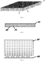
- the present application adopts an optical-grade glass material as a main material of the light guide plate. Referencing to FIG. 1 and FIG. 2 , wherein FIG.
- FIG. 1 illustrates a three-dimensional structural schematic diagram on the light guide plate in the present disclosure
- FIG. 2 illustrates a structural schematic diagram on a cross section of the light guide plate in the present disclosure.
- the main body of the light guide plate 10 of the present application is made of an optical-glass material
- the light guide plate 10 has a built-in cavity 20
- the built-in cavity 20 is filled with a conductive hydrogel 21
- each end of the light guide plate 10 has an electrode arranged to connect electronically to the conductive hydrogel in the cavity (not shown in the figures);
- the conductive hydrogel is in a liquid state when it is not electrified, and becomes a colloidal state when being electrified.
- the hydrogel is a hybrid hydrogel reinforced by a plurality of tiny crystal particles. Adding tiny crystal particles into the conductive hydrogel is able to enhance a function of the light guide plate 10 in both light reflection and light diffuse reflection.
- FIG. 4 which illustrates a schematic diagram on a light refraction direction of the light guide plate in the present disclosure, after a light from a light source 60 enters the light guide plate 10, the conductive hydrogel 21 in the built-in cavity 20 of the light guide plate 10 becomes a colloidal state after being electrified.
- the light guide plate 10 When transmitting in a colloid in the light guide plate 10, the light can encounter the tiny crystal particles (not shown in the figures), since the tiny crystal particles have a function of reflecting light, the light can be reflected and diffusely reflected by the tiny crystal particles before emitting, which makes more light be able to penetrate out of the light guide plate 10, thus greatly improves a light effect of the light guide plate 10.
- FIG. 5 which illustrates a schematic diagram on a light refraction direction of the light guide plate in the prior art, after the light from the light source 60 enters a light guide plate 10', the light guide plate 10' transmits light in a relatively simple way, there is no diffuse reflection effect formed, thus the light effect is poor.
- FIG. 3 which illustrates a schematic diagram on a heat transmission direction of the light guide plate in the present disclosure
- FIG. 3 shows the heat dissipation of the light guide plate 10 in accordance with the light source 60. Since the hydrogel has not only a high light transmittance, but also a function of heat conduction.
- the hydrogel becomes a colloid before starting to work, the hydrogel further has a characteristic of flow accelerating after being heated by the light from the light source 60.
- heat of a section of the light guide plate 10 close to the light source 60 is increased, making an end of the light guide plate 10 away from the light source 60 and an end close to the light source 60 form a temperature difference.
- a convective fluidity is enhanced, which continuously transmits the heat from the end close to the light source 60 to the end away from the light source 60, making the function of heat conduction of the light guide plate 10 in the present disclosure be further strengthened, that has effectively solved a problem of the backlight module on heat dissipation.
- a color gamut of a backlight needs to be further improved, it may further add a plurality of quantum dots or fluorescent powder into the conductive hydrogel, to increase a display color gamut, and achieve an image quality effect with an ultra-high color gamut.
- the present disclosure further provides a preparation method for the conductive hydrogel in the light guide plate described above, wherein comprising a plurality of following steps:
- N-methylene bisacrylamide as a cross-linking agent and potassium persulfate as an initiator, adopting an aqueous solution polymerization method to prepare a conductive hydrogel composed of polyacrylic acid and the tiny crystal particles.
- the present disclosure further provides a backlight module, the backlight module is an edge-type backlight module, composed by adopting the light guide plate described above.
- the backlight module is an edge-type backlight module, composed by adopting the light guide plate described above.
- a plurality of specific functions of the light guide plate is as same as the light guide plate described above, thus no more details are described herein.
Landscapes
- Physics & Mathematics (AREA)
- Chemical & Material Sciences (AREA)
- General Physics & Mathematics (AREA)
- Optics & Photonics (AREA)
- Organic Chemistry (AREA)
- Chemical Kinetics & Catalysis (AREA)
- Medicinal Chemistry (AREA)
- Polymers & Plastics (AREA)
- Health & Medical Sciences (AREA)
- Nonlinear Science (AREA)
- Dispersion Chemistry (AREA)
- Mathematical Physics (AREA)
- Crystallography & Structural Chemistry (AREA)
- Engineering & Computer Science (AREA)
- Manufacturing & Machinery (AREA)
- Planar Illumination Modules (AREA)
Abstract
Description
- This application claims priority to
Chinese Patent Application No. 201811603495.1, filed on 26.12.2018 - The present disclosure relates to the technical field of LED display, and to a backlight module, a light guide plate, and a preparation method for conductive hydrogel of the light guide plate.
- For an LCD backlight module, a light guide plate is a main key component of an edge-type backlight module. A traditional light guide plate is mainly made of a plastic (PMMA, MS, and more), in addition, an optical-grade glass light guide plate has been successively applied in a plurality of backlight module products. In the prior art, an application of the light guide plate has a problem of heat concentration in the backlight module, making a heat dissipation design for a system insufficient.
- Therefore, the current technology needs to be improved and developed.
- According to the above described defects, the purpose of the present disclosure is providing a light guide plate and a backlight module thereof that is able to accelerate a heat dissipation and has a high light transmittance, as well as a preparation method for a hydrogel built in the light guide plate.
- A technical solution of the present disclosure to solve the technical problems is as follows:
- A light guide plate, wherein a main body of the light guide plate is made of an optical-glass material, the light guide plate has a built-in cavity, the cavity is filled with a conductive hydrogel, and each end of the light guide plate has an electrode arranged to connect electronically to the conductive hydrogel in the cavity; the conductive hydrogel is in a liquid state when it is not electrified, and becomes a colloidal state when the conductive hydrogel in the cavity is electrified.
- As an improved technical solution, after the light guide plate is electrified and the conductive hydrogel forms a colloidal state before starting to work, heat of a section of the light guide plate close to a light source is increased, making an end of the light guide plate away from the light source and an end close to the light source form a temperature difference.
- As an improved technical solution, the conductive hydrogel has a plurality of tiny crystal particles added to enhance a function of the light guide plate in both light reflection and light diffuse reflection.
- As an improved technical solution, the conductive hydrogel is a hybrid hydrogel having a plurality of tiny crystal particles enhanced.
- As an improved technical solution, the conductive hydrogel has a plurality of quantum dots added to increase a display color gamut.
- As an improved technical solution, the conductive hydrogel has a plurality of fluorescent powder added to increase the display color gamut.
- The present disclosure further provides a method for preparing the conductive hydrogel, applied to preparing the conductive hydrogel in the light guide plate described above, wherein comprising a plurality of following steps:
- dispersing a plurality of tiny crystal particles into an aqueous solution of acrylic monomer;
- applying N-methylene bisacrylamide as a cross-linking agent and potassium persulfate as an initiator, adopting an aqueous solution polymerization method to prepare a conductive hydrogel composed of polyacrylic acid and the tiny crystal particles.
- As an improved technical solution, the conductive hydrogel has a plurality of quantum dots added.
- As an improved technical solution, the conductive hydrogel has a plurality of fluorescent powder added.
- As an improved technical solution, the conductive hydrogel is a hybrid hydrogel having a plurality of tiny crystal particles enhanced.
- The present disclosure further provides a backlight module, the backlight module is an edge-type backlight module, the backlight module comprises a light guide plate, a main body of the light guide plate is made of an optical-glass material, the light guide plate has a built-in cavity, the cavity is filled with a conductive hydrogel, and each end of the light guide plate has an electrode arranged to connect electronically to the conductive hydrogel in the cavity; the conductive hydrogel is in a liquid state when it is not electrified, and becomes a colloidal state when the conductive hydrogel in the cavity is electrified.
- As an improved technical solution, the conductive hydrogel has a plurality of tiny crystal particles added to enhance a function of the light guide plate in both light reflection and light diffuse reflection.
- As an improved technical solution, the conductive hydrogel is a hybrid hydrogel having a plurality of tiny crystal particles enhanced.
- As an improved technical solution, the conductive hydrogel has a plurality of quantum dots added, to increase a display color gamut.
- As an improved technical solution, the conductive hydrogel has a plurality of fluorescent powder added, to increase a display color gamut.
- Comparing to a light guide plate made of plastic in the prior art, the light guide plate in the present disclosure adopts a main body made of an optical-glass material, arranges a cavity in the light guide plate, and the cavity is filled with a conductive hydrogel, by using a character of the conductive hydrogel being in a liquid state when it is not electrified, and becomes a colloidal state when it is electrified, the conductive hydrogel converts between the liquid state and the colloidal state, and the tiny crystal particles in the conductive hydrogel make a plurality of deflections under an action of an electronic field, when a light passes through a crystal having a fixed deflection direction, an optical rotation effect happens, making the light be able to transmit in the light guide plate in the colloidal state. While the tiny crystal particles may further enhance the function of the reflection and diffuse reflection of the light, allowing more light to penetrate, so as to improve a light efficiency; if further adding a material of the quantum dots or the fluorescent powder to the conductive hydrogel, it may further improve an ultra-high color gamut of the backlight, being able to make a display effect of a liquid crystal display device better.
-
-
FIG. 1 illustrates a three-dimensional structural schematic diagram on the light guide plate in the present disclosure; -
FIG. 2 illustrates a structural schematic diagram on a cross section of the light guide plate in the present disclosure; -
FIG. 3 illustrates a schematic diagram on a heat transmission direction of the light guide plate in the present disclosure; -
FIG. 4 illustrates a schematic diagram on a light refraction direction of the light guide plate in the present disclosure; -
FIG. 5 illustrates a schematic diagram on a light refraction direction of the light guide plate in the prior art. - In order to make the purpose, technical solution and the advantages of the present disclosure clearer and more explicit, further detailed descriptions of the present disclosure are stated here, referencing to the attached drawings and some embodiments of the present disclosure. It should be understood that the detailed embodiments of the disclosure described here are used to explain the present disclosure only, instead of limiting the present disclosure.
- As an important part of a liquid crystal display module, an effect of a backlight module determines a display effect of the liquid crystal display module, while a light guide plate is a key part of the backlight module, and a light guide effect of the light guide plate directly determines the display effect high or low. In an edge-type backlight module, a traditional light guide plate generally adopts a plastic material, which has a poor light guide effect and easily accumulates heat, and the heat in the backlight module has no way to be effectively dissipated, making a heat dissipation design of a system rather difficult. The present application adopts an optical-grade glass material as a main material of the light guide plate. Referencing to
FIG. 1 and FIG. 2 , whereinFIG. 1 illustrates a three-dimensional structural schematic diagram on the light guide plate in the present disclosure;FIG. 2 illustrates a structural schematic diagram on a cross section of the light guide plate in the present disclosure. CombiningFIG. 1 and FIG. 2 , the main body of thelight guide plate 10 of the present application is made of an optical-glass material, thelight guide plate 10 has a built-incavity 20, the built-incavity 20 is filled with aconductive hydrogel 21, and each end of thelight guide plate 10 has an electrode arranged to connect electronically to the conductive hydrogel in the cavity (not shown in the figures); the conductive hydrogel is in a liquid state when it is not electrified, and becomes a colloidal state when being electrified. Specifically, the hydrogel is a hybrid hydrogel reinforced by a plurality of tiny crystal particles. Adding tiny crystal particles into the conductive hydrogel is able to enhance a function of thelight guide plate 10 in both light reflection and light diffuse reflection. Combing withFIG. 4 , which illustrates a schematic diagram on a light refraction direction of the light guide plate in the present disclosure, after a light from alight source 60 enters thelight guide plate 10, theconductive hydrogel 21 in the built-incavity 20 of thelight guide plate 10 becomes a colloidal state after being electrified. When transmitting in a colloid in thelight guide plate 10, the light can encounter the tiny crystal particles (not shown in the figures), since the tiny crystal particles have a function of reflecting light, the light can be reflected and diffusely reflected by the tiny crystal particles before emitting, which makes more light be able to penetrate out of thelight guide plate 10, thus greatly improves a light effect of thelight guide plate 10. Compared to a light guide plate in the prior art, as shown inFIG. 5 , which illustrates a schematic diagram on a light refraction direction of the light guide plate in the prior art, after the light from thelight source 60 enters a light guide plate 10', the light guide plate 10' transmits light in a relatively simple way, there is no diffuse reflection effect formed, thus the light effect is poor. - In addition, for a light guide plate, due to a light guide function, it also needs a design for heat dissipation, while a method of the light guide plate in the present disclosure adopting the conductive hydrogel filled in the cavity may further improve a problem of heat dissipation in the backlight module. Shown as
FIG. 3 , which illustrates a schematic diagram on a heat transmission direction of the light guide plate in the present disclosure,FIG. 3 shows the heat dissipation of thelight guide plate 10 in accordance with thelight source 60. Since the hydrogel has not only a high light transmittance, but also a function of heat conduction. After thelight guide plate 10 is electrified, the hydrogel becomes a colloid before starting to work, the hydrogel further has a characteristic of flow accelerating after being heated by the light from thelight source 60. After being heated by thelight source 60, heat of a section of thelight guide plate 10 close to thelight source 60 is increased, making an end of thelight guide plate 10 away from thelight source 60 and an end close to thelight source 60 form a temperature difference. After the hydrogel is heated, a convective fluidity is enhanced, which continuously transmits the heat from the end close to thelight source 60 to the end away from thelight source 60, making the function of heat conduction of thelight guide plate 10 in the present disclosure be further strengthened, that has effectively solved a problem of the backlight module on heat dissipation. - Based on the conductive hydrogel mentioned above, if a color gamut of a backlight needs to be further improved, it may further add a plurality of quantum dots or fluorescent powder into the conductive hydrogel, to increase a display color gamut, and achieve an image quality effect with an ultra-high color gamut.
- The present disclosure further provides a preparation method for the conductive hydrogel in the light guide plate described above, wherein comprising a plurality of following steps:
- dispersing a plurality of tiny crystal particles into an aqueous solution of acrylic monomer;
- applying N-methylene bisacrylamide as a cross-linking agent and potassium persulfate as an initiator, adopting an aqueous solution polymerization method to prepare a conductive hydrogel composed of polyacrylic acid and the tiny crystal particles.
- The present disclosure further provides a backlight module, the backlight module is an edge-type backlight module, composed by adopting the light guide plate described above. A plurality of specific functions of the light guide plate is as same as the light guide plate described above, thus no more details are described herein.
- It should be understood that, the application of the present disclosure is not limited to the above examples listed. Ordinary technical personnel in this field can improve or change the applications according to the above descriptions, all of these improvements and transforms should belong to the scope of protection in the appended claims of the present disclosure.
Claims (15)
- A light guide plate, wherein a main body of the light guide plate is made of an optical-glass material, the light guide plate has a built-in cavity, the cavity is filled with a conductive hydrogel, and each end of the light guide plate has an electrode arranged to connect electronically to the conductive hydrogel in the cavity; the conductive hydrogel is in a liquid state when it is not electrified, and becomes a colloidal state when the conductive hydrogel in the cavity is electrified.
- The light guide plate according to claim 1, wherein after the light guide plate is electrified and the conductive hydrogel forms a colloidal state before starting to work, heat of a section of the light guide plate close to a light source is increased, making an end of the light guide plate away from the light source and an end close to the light source form a temperature difference.
- The light guide plate according to claim 1, wherein the conductive hydrogel has a plurality of tiny crystal particles added to enhance a function of the light guide plate in both light reflection and light diffuse reflection.
- The light guide plate according to claim 3, wherein the conductive hydrogel is a hybrid hydrogel having a plurality of tiny crystal particles enhanced.
- The light guide plate according to claim 1, wherein the conductive hydrogel has a plurality of quantum dots added to increase a display color gamut.
- The light guide plate according to claim 1, wherein the conductive hydrogel has a plurality of fluorescent powder added to increase a display color gamut.
- A preparation method for a conductive hydrogel, applied to preparing the conductive hydrogel in the light guide plate according to claim 1, wherein comprising a plurality of following steps:dispersing a plurality of tiny crystal particles into an aqueous solution of acrylic monomer;applying N-methylene bisacrylamide as a cross-linking agent and potassium persulfate as an initiator, adopting an aqueous solution polymerization method to prepare a conductive hydrogel composed of polyacrylic acid and the tiny crystal particles.
- The preparation method according to claim 7, wherein the conductive hydrogel has a plurality of quantum dots added.
- The preparation method according to claim 7, wherein the conductive hydrogel has a plurality of fluorescent powder added.
- The preparation method according to claim 7, wherein the conductive hydrogel is a hybrid hydrogel having a plurality of tiny crystal particles enhanced.
- A backlight module, the backlight module is an edge-type backlight module, wherein the backlight module comprises a light guide plate, a main body of the light guide plate is made of an optical-glass material, the light guide plate has a built-in cavity, the cavity is filled with a conductive hydrogel, and each end of the light guide plate has an electrode arranged to connect electronically to the conductive hydrogel in the cavity; the conductive hydrogel is in a liquid state when it is not electrified, and becomes a colloidal state when the conductive hydrogel in the cavity is electrified.
- The backlight module according to claim 11, wherein the conductive hydrogel has a plurality of tiny crystal particles added to enhance a function of the light guide plate in both light reflection and light diffuse reflection.
- The backlight module according to claim 11, wherein the conductive hydrogel is a hybrid hydrogel having a plurality of tiny crystal particles enhanced.
- The backlight module according to claim 11, wherein the conductive hydrogel has a plurality of quantum dots added, to increase a display color gamut.
- The backlight module according to claim 11, wherein, the conductive hydrogel has a plurality of fluorescent powder added, to increase the display color gamut.
Applications Claiming Priority (2)
| Application Number | Priority Date | Filing Date | Title |
|---|---|---|---|
| CN201811603495.1A CN111367007B (en) | 2018-12-26 | 2018-12-26 | Backlight module, light guide plate and preparation method of conductive hydrogel |
| PCT/CN2019/126820 WO2020135240A1 (en) | 2018-12-26 | 2019-12-20 | Backlight module, light guide plate, and preparation method for conductive hydrogel of light guide plate |
Publications (3)
| Publication Number | Publication Date |
|---|---|
| EP3904924A1 true EP3904924A1 (en) | 2021-11-03 |
| EP3904924A4 EP3904924A4 (en) | 2022-08-17 |
| EP3904924B1 EP3904924B1 (en) | 2023-09-06 |
Family
ID=71128491
Family Applications (1)
| Application Number | Title | Priority Date | Filing Date |
|---|---|---|---|
| EP19903702.9A Active EP3904924B1 (en) | 2018-12-26 | 2019-12-20 | Light guide plate, method of manufacturing the light guide plate, and backlight |
Country Status (4)
| Country | Link |
|---|---|
| US (1) | US11300723B2 (en) |
| EP (1) | EP3904924B1 (en) |
| CN (1) | CN111367007B (en) |
| WO (1) | WO2020135240A1 (en) |
Families Citing this family (1)
| Publication number | Priority date | Publication date | Assignee | Title |
|---|---|---|---|---|
| CN117138066B (en) * | 2023-07-31 | 2026-01-30 | 南方科技大学 | A conductive hydrogel neural probe and its preparation method |
Family Cites Families (22)
| Publication number | Priority date | Publication date | Assignee | Title |
|---|---|---|---|---|
| CA2053998A1 (en) * | 1990-10-23 | 1992-04-24 | American Cyanamid Company | Narrow band radiation filter films |
| JPH0895042A (en) * | 1994-09-22 | 1996-04-12 | Nippondenso Co Ltd | Liquid crystal display |
| JPH1186621A (en) * | 1997-09-03 | 1999-03-30 | Sharp Corp | Lighting equipment |
| JP2000131688A (en) * | 1998-10-22 | 2000-05-12 | Advanced Display Inc | Lighting equipment |
| JP4074977B2 (en) * | 2001-02-02 | 2008-04-16 | ミネベア株式会社 | Surface lighting device |
| JP4975970B2 (en) * | 2005-01-21 | 2012-07-11 | 日本エクスラン工業株式会社 | Sorptive heat exchange module and method for producing the same |
| TWI417604B (en) * | 2005-12-28 | 2013-12-01 | 半導體能源研究所股份有限公司 | Display device |
| CN100406484C (en) * | 2006-01-10 | 2008-07-30 | 华侨大学 | Graphite/potassium polyacrylate conductive hydrogel and preparation method thereof |
| JP2008003254A (en) * | 2006-06-21 | 2008-01-10 | Idemitsu Kosan Co Ltd | Multi-layer sheet for reflecting light, reflector using the same, illumination device and liquid crystal display device |
| WO2009102733A2 (en) * | 2008-02-12 | 2009-08-20 | Qualcomm Mems Technologies, Inc. | Integrated front light diffuser for reflective displays |
| CN201251634Y (en) * | 2008-09-11 | 2009-06-03 | 扬昕精密股份有限公司 | Light guide plate of backlight module |
| JP4982627B2 (en) * | 2009-08-13 | 2012-07-25 | 株式会社タイカ | Optical gel member, method of assembling optical device using the same, and optical device |
| TW201142207A (en) * | 2010-05-24 | 2011-12-01 | Chi Lin Technology Co Ltd | Illuminating device |
| WO2014033585A2 (en) * | 2012-08-31 | 2014-03-06 | Koninklijke Philips N.V. | Illumination device based on thermally conductive sheet with light diffusing particles |
| CN103676317A (en) * | 2013-12-11 | 2014-03-26 | 合肥京东方光电科技有限公司 | Light guide plate, backlight source and LCD device |
| CN105891936B (en) * | 2016-05-20 | 2019-11-01 | 京东方科技集团股份有限公司 | Light-guide device and preparation method thereof and backlight module |
| US20180067253A1 (en) * | 2016-06-13 | 2018-03-08 | Innolux Corporation | Display device |
| CN106249481B (en) * | 2016-09-18 | 2020-05-05 | 青岛海信电器股份有限公司 | A kind of backlight module and preparation method of light guide plate |
| CN106519287A (en) * | 2016-11-18 | 2017-03-22 | 陕西品达石化有限公司 | Preparation method of cellulose based conductive hydrogel |
| CN106895278A (en) * | 2017-03-20 | 2017-06-27 | 京东方科技集团股份有限公司 | A kind of preparation method of LED, backlight module, display device and backlight module |
| CN108794773B (en) * | 2018-06-29 | 2021-03-23 | 四川理工学院 | Preparation method of conductive hydrogel |
| CN113717405B (en) * | 2021-09-24 | 2024-05-03 | 天津中电新能源研究院有限公司 | Flexible conductive hydrogel and preparation method and application thereof |
-
2018
- 2018-12-26 CN CN201811603495.1A patent/CN111367007B/en active Active
-
2019
- 2019-12-20 US US16/973,960 patent/US11300723B2/en active Active
- 2019-12-20 EP EP19903702.9A patent/EP3904924B1/en active Active
- 2019-12-20 WO PCT/CN2019/126820 patent/WO2020135240A1/en not_active Ceased
Also Published As
| Publication number | Publication date |
|---|---|
| EP3904924B1 (en) | 2023-09-06 |
| US20210255382A1 (en) | 2021-08-19 |
| CN111367007A (en) | 2020-07-03 |
| CN111367007B (en) | 2021-07-06 |
| US11300723B2 (en) | 2022-04-12 |
| EP3904924A4 (en) | 2022-08-17 |
| WO2020135240A1 (en) | 2020-07-02 |
Similar Documents
| Publication | Publication Date | Title |
|---|---|---|
| TWI554796B (en) | Systems and methods for coupling light into a transparent sheet | |
| CN105954933B (en) | Display device and preparation method thereof | |
| CN104570483A (en) | A kind of backlight module and display device | |
| CN107229157A (en) | Transparent display and preparation method thereof | |
| CN101561085A (en) | Wide-angle LED light source | |
| JP2007115695A (en) | Backlight structure | |
| US20160245976A1 (en) | Backlight module, display panel and display device | |
| US11300723B2 (en) | Backlight module, light guide plate, and preparation method for conductive hydrogel of light guide plate | |
| JP2018205414A (en) | Optical structure, display device | |
| CN104819433A (en) | Oval light spot realizing device, light spot adjusting device and operating lamp | |
| TWI286631B (en) | Compact lighting system and display device | |
| US9588288B2 (en) | Backlight module and liquid crystal display device using same | |
| CN211454029U (en) | A condensing light path display | |
| CN203455506U (en) | Light guiding rod and linear light source apparatus manufactured by using the same | |
| CN208207271U (en) | Novel Microstructure light guide plate and its display module | |
| WO2013139049A1 (en) | Side-type backlight module | |
| EP3454115A1 (en) | Light guide assembly, backlight module and display device | |
| JP2011221196A (en) | Fiber-shaped light modulation element, illuminating device, and display device | |
| CN102466168B (en) | Line light source and LCD (liquid crystal display) device | |
| KR100420615B1 (en) | Flat type backlight for LCD using optical fiber | |
| US20140160392A1 (en) | Optical fiber for backlight module, backlight module and liquid crystal display device | |
| TWM267769U (en) | Collimated scanning backlight device | |
| TW200916911A (en) | Backlight module | |
| CN116360153A (en) | An external backlight module of a luminous power device, a display module and a display | |
| CN116755277A (en) | Backlight module and display device |
Legal Events
| Date | Code | Title | Description |
|---|---|---|---|
| STAA | Information on the status of an ep patent application or granted ep patent |
Free format text: STATUS: THE INTERNATIONAL PUBLICATION HAS BEEN MADE |
|
| PUAI | Public reference made under article 153(3) epc to a published international application that has entered the european phase |
Free format text: ORIGINAL CODE: 0009012 |
|
| STAA | Information on the status of an ep patent application or granted ep patent |
Free format text: STATUS: REQUEST FOR EXAMINATION WAS MADE |
|
| 17P | Request for examination filed |
Effective date: 20201125 |
|
| AK | Designated contracting states |
Kind code of ref document: A1 Designated state(s): AL AT BE BG CH CY CZ DE DK EE ES FI FR GB GR HR HU IE IS IT LI LT LU LV MC MK MT NL NO PL PT RO RS SE SI SK SM TR |
|
| DAV | Request for validation of the european patent (deleted) | ||
| DAX | Request for extension of the european patent (deleted) | ||
| A4 | Supplementary search report drawn up and despatched |
Effective date: 20220719 |
|
| RIC1 | Information provided on ipc code assigned before grant |
Ipc: G02B 1/06 20060101ALI20220713BHEP Ipc: C08F 222/38 20060101ALI20220713BHEP Ipc: C08F 220/18 20060101ALI20220713BHEP Ipc: G02F 1/1333 20060101ALI20220713BHEP Ipc: F21V 8/00 20060101ALI20220713BHEP Ipc: C08F 220/06 20060101ALI20220713BHEP Ipc: G02F 1/13357 20060101ALI20220713BHEP Ipc: G02B 6/00 20060101AFI20220713BHEP |
|
| GRAP | Despatch of communication of intention to grant a patent |
Free format text: ORIGINAL CODE: EPIDOSNIGR1 |
|
| STAA | Information on the status of an ep patent application or granted ep patent |
Free format text: STATUS: GRANT OF PATENT IS INTENDED |
|
| RIC1 | Information provided on ipc code assigned before grant |
Ipc: G02B 1/06 20060101ALI20230307BHEP Ipc: C08F 222/38 20060101ALI20230307BHEP Ipc: C08F 220/18 20060101ALI20230307BHEP Ipc: G02F 1/1333 20060101ALI20230307BHEP Ipc: F21V 8/00 20060101ALI20230307BHEP Ipc: C08F 220/06 20060101ALI20230307BHEP Ipc: G02F 1/13357 20060101ALI20230307BHEP Ipc: G02B 6/00 20060101AFI20230307BHEP |
|
| INTG | Intention to grant announced |
Effective date: 20230405 |
|
| GRAS | Grant fee paid |
Free format text: ORIGINAL CODE: EPIDOSNIGR3 |
|
| GRAA | (expected) grant |
Free format text: ORIGINAL CODE: 0009210 |
|
| STAA | Information on the status of an ep patent application or granted ep patent |
Free format text: STATUS: THE PATENT HAS BEEN GRANTED |
|
| AK | Designated contracting states |
Kind code of ref document: B1 Designated state(s): AL AT BE BG CH CY CZ DE DK EE ES FI FR GB GR HR HU IE IS IT LI LT LU LV MC MK MT NL NO PL PT RO RS SE SI SK SM TR |
|
| REG | Reference to a national code |
Ref country code: GB Ref legal event code: FG4D |
|
| P01 | Opt-out of the competence of the unified patent court (upc) registered |
Effective date: 20230807 |
|
| REG | Reference to a national code |
Ref country code: CH Ref legal event code: EP |
|
| REG | Reference to a national code |
Ref country code: IE Ref legal event code: FG4D |
|
| REG | Reference to a national code |
Ref country code: DE Ref legal event code: R096 Ref document number: 602019037149 Country of ref document: DE |
|
| REG | Reference to a national code |
Ref country code: LT Ref legal event code: MG9D |
|
| REG | Reference to a national code |
Ref country code: NL Ref legal event code: MP Effective date: 20230906 |
|
| PG25 | Lapsed in a contracting state [announced via postgrant information from national office to epo] |
Ref country code: GR Free format text: LAPSE BECAUSE OF FAILURE TO SUBMIT A TRANSLATION OF THE DESCRIPTION OR TO PAY THE FEE WITHIN THE PRESCRIBED TIME-LIMIT Effective date: 20231207 |
|
| PG25 | Lapsed in a contracting state [announced via postgrant information from national office to epo] |
Ref country code: SE Free format text: LAPSE BECAUSE OF FAILURE TO SUBMIT A TRANSLATION OF THE DESCRIPTION OR TO PAY THE FEE WITHIN THE PRESCRIBED TIME-LIMIT Effective date: 20230906 Ref country code: RS Free format text: LAPSE BECAUSE OF FAILURE TO SUBMIT A TRANSLATION OF THE DESCRIPTION OR TO PAY THE FEE WITHIN THE PRESCRIBED TIME-LIMIT Effective date: 20230906 Ref country code: NO Free format text: LAPSE BECAUSE OF FAILURE TO SUBMIT A TRANSLATION OF THE DESCRIPTION OR TO PAY THE FEE WITHIN THE PRESCRIBED TIME-LIMIT Effective date: 20231206 Ref country code: LV Free format text: LAPSE BECAUSE OF FAILURE TO SUBMIT A TRANSLATION OF THE DESCRIPTION OR TO PAY THE FEE WITHIN THE PRESCRIBED TIME-LIMIT Effective date: 20230906 Ref country code: LT Free format text: LAPSE BECAUSE OF FAILURE TO SUBMIT A TRANSLATION OF THE DESCRIPTION OR TO PAY THE FEE WITHIN THE PRESCRIBED TIME-LIMIT Effective date: 20230906 Ref country code: HR Free format text: LAPSE BECAUSE OF FAILURE TO SUBMIT A TRANSLATION OF THE DESCRIPTION OR TO PAY THE FEE WITHIN THE PRESCRIBED TIME-LIMIT Effective date: 20230906 Ref country code: GR Free format text: LAPSE BECAUSE OF FAILURE TO SUBMIT A TRANSLATION OF THE DESCRIPTION OR TO PAY THE FEE WITHIN THE PRESCRIBED TIME-LIMIT Effective date: 20231207 Ref country code: FI Free format text: LAPSE BECAUSE OF FAILURE TO SUBMIT A TRANSLATION OF THE DESCRIPTION OR TO PAY THE FEE WITHIN THE PRESCRIBED TIME-LIMIT Effective date: 20230906 |
|
| REG | Reference to a national code |
Ref country code: AT Ref legal event code: MK05 Ref document number: 1609262 Country of ref document: AT Kind code of ref document: T Effective date: 20230906 |
|
| PG25 | Lapsed in a contracting state [announced via postgrant information from national office to epo] |
Ref country code: NL Free format text: LAPSE BECAUSE OF FAILURE TO SUBMIT A TRANSLATION OF THE DESCRIPTION OR TO PAY THE FEE WITHIN THE PRESCRIBED TIME-LIMIT Effective date: 20230906 |
|
| PG25 | Lapsed in a contracting state [announced via postgrant information from national office to epo] |
Ref country code: IS Free format text: LAPSE BECAUSE OF FAILURE TO SUBMIT A TRANSLATION OF THE DESCRIPTION OR TO PAY THE FEE WITHIN THE PRESCRIBED TIME-LIMIT Effective date: 20240106 |
|
| PG25 | Lapsed in a contracting state [announced via postgrant information from national office to epo] |
Ref country code: AT Free format text: LAPSE BECAUSE OF FAILURE TO SUBMIT A TRANSLATION OF THE DESCRIPTION OR TO PAY THE FEE WITHIN THE PRESCRIBED TIME-LIMIT Effective date: 20230906 |
|
| PG25 | Lapsed in a contracting state [announced via postgrant information from national office to epo] |
Ref country code: ES Free format text: LAPSE BECAUSE OF FAILURE TO SUBMIT A TRANSLATION OF THE DESCRIPTION OR TO PAY THE FEE WITHIN THE PRESCRIBED TIME-LIMIT Effective date: 20230906 |
|
| PG25 | Lapsed in a contracting state [announced via postgrant information from national office to epo] |
Ref country code: SM Free format text: LAPSE BECAUSE OF FAILURE TO SUBMIT A TRANSLATION OF THE DESCRIPTION OR TO PAY THE FEE WITHIN THE PRESCRIBED TIME-LIMIT Effective date: 20230906 Ref country code: RO Free format text: LAPSE BECAUSE OF FAILURE TO SUBMIT A TRANSLATION OF THE DESCRIPTION OR TO PAY THE FEE WITHIN THE PRESCRIBED TIME-LIMIT Effective date: 20230906 Ref country code: IS Free format text: LAPSE BECAUSE OF FAILURE TO SUBMIT A TRANSLATION OF THE DESCRIPTION OR TO PAY THE FEE WITHIN THE PRESCRIBED TIME-LIMIT Effective date: 20240106 Ref country code: ES Free format text: LAPSE BECAUSE OF FAILURE TO SUBMIT A TRANSLATION OF THE DESCRIPTION OR TO PAY THE FEE WITHIN THE PRESCRIBED TIME-LIMIT Effective date: 20230906 Ref country code: EE Free format text: LAPSE BECAUSE OF FAILURE TO SUBMIT A TRANSLATION OF THE DESCRIPTION OR TO PAY THE FEE WITHIN THE PRESCRIBED TIME-LIMIT Effective date: 20230906 Ref country code: CZ Free format text: LAPSE BECAUSE OF FAILURE TO SUBMIT A TRANSLATION OF THE DESCRIPTION OR TO PAY THE FEE WITHIN THE PRESCRIBED TIME-LIMIT Effective date: 20230906 Ref country code: AT Free format text: LAPSE BECAUSE OF FAILURE TO SUBMIT A TRANSLATION OF THE DESCRIPTION OR TO PAY THE FEE WITHIN THE PRESCRIBED TIME-LIMIT Effective date: 20230906 Ref country code: PT Free format text: LAPSE BECAUSE OF FAILURE TO SUBMIT A TRANSLATION OF THE DESCRIPTION OR TO PAY THE FEE WITHIN THE PRESCRIBED TIME-LIMIT Effective date: 20240108 Ref country code: SK Free format text: LAPSE BECAUSE OF FAILURE TO SUBMIT A TRANSLATION OF THE DESCRIPTION OR TO PAY THE FEE WITHIN THE PRESCRIBED TIME-LIMIT Effective date: 20230906 |
|
| PG25 | Lapsed in a contracting state [announced via postgrant information from national office to epo] |
Ref country code: PL Free format text: LAPSE BECAUSE OF FAILURE TO SUBMIT A TRANSLATION OF THE DESCRIPTION OR TO PAY THE FEE WITHIN THE PRESCRIBED TIME-LIMIT Effective date: 20230906 Ref country code: IT Free format text: LAPSE BECAUSE OF FAILURE TO SUBMIT A TRANSLATION OF THE DESCRIPTION OR TO PAY THE FEE WITHIN THE PRESCRIBED TIME-LIMIT Effective date: 20230906 |
|
| REG | Reference to a national code |
Ref country code: DE Ref legal event code: R097 Ref document number: 602019037149 Country of ref document: DE |
|
| PG25 | Lapsed in a contracting state [announced via postgrant information from national office to epo] |
Ref country code: DK Free format text: LAPSE BECAUSE OF FAILURE TO SUBMIT A TRANSLATION OF THE DESCRIPTION OR TO PAY THE FEE WITHIN THE PRESCRIBED TIME-LIMIT Effective date: 20230906 |
|
| PLBE | No opposition filed within time limit |
Free format text: ORIGINAL CODE: 0009261 |
|
| STAA | Information on the status of an ep patent application or granted ep patent |
Free format text: STATUS: NO OPPOSITION FILED WITHIN TIME LIMIT |
|
| PG25 | Lapsed in a contracting state [announced via postgrant information from national office to epo] |
Ref country code: DK Free format text: LAPSE BECAUSE OF FAILURE TO SUBMIT A TRANSLATION OF THE DESCRIPTION OR TO PAY THE FEE WITHIN THE PRESCRIBED TIME-LIMIT Effective date: 20230906 Ref country code: SI Free format text: LAPSE BECAUSE OF FAILURE TO SUBMIT A TRANSLATION OF THE DESCRIPTION OR TO PAY THE FEE WITHIN THE PRESCRIBED TIME-LIMIT Effective date: 20230906 |
|
| REG | Reference to a national code |
Ref country code: CH Ref legal event code: PL |
|
| 26N | No opposition filed |
Effective date: 20240607 |
|
| PG25 | Lapsed in a contracting state [announced via postgrant information from national office to epo] |
Ref country code: LU Free format text: LAPSE BECAUSE OF NON-PAYMENT OF DUE FEES Effective date: 20231220 |
|
| PG25 | Lapsed in a contracting state [announced via postgrant information from national office to epo] |
Ref country code: MC Free format text: LAPSE BECAUSE OF FAILURE TO SUBMIT A TRANSLATION OF THE DESCRIPTION OR TO PAY THE FEE WITHIN THE PRESCRIBED TIME-LIMIT Effective date: 20230906 |
|
| REG | Reference to a national code |
Ref country code: BE Ref legal event code: MM Effective date: 20231231 |
|
| PG25 | Lapsed in a contracting state [announced via postgrant information from national office to epo] |
Ref country code: MC Free format text: LAPSE BECAUSE OF FAILURE TO SUBMIT A TRANSLATION OF THE DESCRIPTION OR TO PAY THE FEE WITHIN THE PRESCRIBED TIME-LIMIT Effective date: 20230906 Ref country code: LU Free format text: LAPSE BECAUSE OF NON-PAYMENT OF DUE FEES Effective date: 20231220 |
|
| REG | Reference to a national code |
Ref country code: IE Ref legal event code: MM4A |
|
| PG25 | Lapsed in a contracting state [announced via postgrant information from national office to epo] |
Ref country code: IE Free format text: LAPSE BECAUSE OF NON-PAYMENT OF DUE FEES Effective date: 20231220 |
|
| PG25 | Lapsed in a contracting state [announced via postgrant information from national office to epo] |
Ref country code: BE Free format text: LAPSE BECAUSE OF NON-PAYMENT OF DUE FEES Effective date: 20231231 |
|
| PG25 | Lapsed in a contracting state [announced via postgrant information from national office to epo] |
Ref country code: FR Free format text: LAPSE BECAUSE OF NON-PAYMENT OF DUE FEES Effective date: 20231231 |
|
| PG25 | Lapsed in a contracting state [announced via postgrant information from national office to epo] |
Ref country code: CH Free format text: LAPSE BECAUSE OF NON-PAYMENT OF DUE FEES Effective date: 20231231 |
|
| PG25 | Lapsed in a contracting state [announced via postgrant information from national office to epo] |
Ref country code: IE Free format text: LAPSE BECAUSE OF NON-PAYMENT OF DUE FEES Effective date: 20231220 Ref country code: FR Free format text: LAPSE BECAUSE OF NON-PAYMENT OF DUE FEES Effective date: 20231231 Ref country code: CH Free format text: LAPSE BECAUSE OF NON-PAYMENT OF DUE FEES Effective date: 20231231 Ref country code: BE Free format text: LAPSE BECAUSE OF NON-PAYMENT OF DUE FEES Effective date: 20231231 |
|
| PG25 | Lapsed in a contracting state [announced via postgrant information from national office to epo] |
Ref country code: BG Free format text: LAPSE BECAUSE OF FAILURE TO SUBMIT A TRANSLATION OF THE DESCRIPTION OR TO PAY THE FEE WITHIN THE PRESCRIBED TIME-LIMIT Effective date: 20230906 |
|
| PG25 | Lapsed in a contracting state [announced via postgrant information from national office to epo] |
Ref country code: BG Free format text: LAPSE BECAUSE OF FAILURE TO SUBMIT A TRANSLATION OF THE DESCRIPTION OR TO PAY THE FEE WITHIN THE PRESCRIBED TIME-LIMIT Effective date: 20230906 |
|
| PG25 | Lapsed in a contracting state [announced via postgrant information from national office to epo] |
Ref country code: CY Free format text: LAPSE BECAUSE OF FAILURE TO SUBMIT A TRANSLATION OF THE DESCRIPTION OR TO PAY THE FEE WITHIN THE PRESCRIBED TIME-LIMIT; INVALID AB INITIO Effective date: 20191220 |
|
| PG25 | Lapsed in a contracting state [announced via postgrant information from national office to epo] |
Ref country code: HU Free format text: LAPSE BECAUSE OF FAILURE TO SUBMIT A TRANSLATION OF THE DESCRIPTION OR TO PAY THE FEE WITHIN THE PRESCRIBED TIME-LIMIT; INVALID AB INITIO Effective date: 20191220 |
|
| PG25 | Lapsed in a contracting state [announced via postgrant information from national office to epo] |
Ref country code: TR Free format text: LAPSE BECAUSE OF FAILURE TO SUBMIT A TRANSLATION OF THE DESCRIPTION OR TO PAY THE FEE WITHIN THE PRESCRIBED TIME-LIMIT Effective date: 20230906 |
|
| PGFP | Annual fee paid to national office [announced via postgrant information from national office to epo] |
Ref country code: DE Payment date: 20251211 Year of fee payment: 7 |
|
| PGFP | Annual fee paid to national office [announced via postgrant information from national office to epo] |
Ref country code: GB Payment date: 20251219 Year of fee payment: 7 |