EP3904850B1 - Intraoral organism monitoring device - Google Patents
Intraoral organism monitoring device Download PDFInfo
- Publication number
- EP3904850B1 EP3904850B1 EP20766584.5A EP20766584A EP3904850B1 EP 3904850 B1 EP3904850 B1 EP 3904850B1 EP 20766584 A EP20766584 A EP 20766584A EP 3904850 B1 EP3904850 B1 EP 3904850B1
- Authority
- EP
- European Patent Office
- Prior art keywords
- sensor
- monitoring device
- light
- subject
- biological monitoring
- Prior art date
- Legal status (The legal status is an assumption and is not a legal conclusion. Google has not performed a legal analysis and makes no representation as to the accuracy of the status listed.)
- Active
Links
Images



Classifications
-
- G—PHYSICS
- G01—MEASURING; TESTING
- G01K—MEASURING TEMPERATURE; MEASURING QUANTITY OF HEAT; THERMALLY-SENSITIVE ELEMENTS NOT OTHERWISE PROVIDED FOR
- G01K1/00—Details of thermometers not specially adapted for particular types of thermometer
- G01K1/02—Means for indicating or recording specially adapted for thermometers
- G01K1/024—Means for indicating or recording specially adapted for thermometers for remote indication
-
- A—HUMAN NECESSITIES
- A61—MEDICAL OR VETERINARY SCIENCE; HYGIENE
- A61B—DIAGNOSIS; SURGERY; IDENTIFICATION
- A61B5/00—Measuring for diagnostic purposes; Identification of persons
- A61B5/0002—Remote monitoring of patients using telemetry, e.g. transmission of vital signals via a communication network
- A61B5/0015—Remote monitoring of patients using telemetry, e.g. transmission of vital signals via a communication network characterised by features of the telemetry system
- A61B5/0022—Monitoring a patient using a global network, e.g. telephone networks, internet
-
- A—HUMAN NECESSITIES
- A61—MEDICAL OR VETERINARY SCIENCE; HYGIENE
- A61B—DIAGNOSIS; SURGERY; IDENTIFICATION
- A61B5/00—Measuring for diagnostic purposes; Identification of persons
- A61B5/0059—Measuring for diagnostic purposes; Identification of persons using light, e.g. diagnosis by transillumination, diascopy, fluorescence
- A61B5/0075—Measuring for diagnostic purposes; Identification of persons using light, e.g. diagnosis by transillumination, diascopy, fluorescence by spectroscopy, i.e. measuring spectra, e.g. Raman spectroscopy, infrared absorption spectroscopy
-
- A—HUMAN NECESSITIES
- A61—MEDICAL OR VETERINARY SCIENCE; HYGIENE
- A61B—DIAGNOSIS; SURGERY; IDENTIFICATION
- A61B5/00—Measuring for diagnostic purposes; Identification of persons
- A61B5/0059—Measuring for diagnostic purposes; Identification of persons using light, e.g. diagnosis by transillumination, diascopy, fluorescence
- A61B5/0082—Measuring for diagnostic purposes; Identification of persons using light, e.g. diagnosis by transillumination, diascopy, fluorescence adapted for particular medical purposes
- A61B5/0088—Measuring for diagnostic purposes; Identification of persons using light, e.g. diagnosis by transillumination, diascopy, fluorescence adapted for particular medical purposes for oral or dental tissue
-
- A—HUMAN NECESSITIES
- A61—MEDICAL OR VETERINARY SCIENCE; HYGIENE
- A61B—DIAGNOSIS; SURGERY; IDENTIFICATION
- A61B5/00—Measuring for diagnostic purposes; Identification of persons
- A61B5/01—Measuring temperature of body parts ; Diagnostic temperature sensing, e.g. for malignant or inflamed tissue
-
- A—HUMAN NECESSITIES
- A61—MEDICAL OR VETERINARY SCIENCE; HYGIENE
- A61B—DIAGNOSIS; SURGERY; IDENTIFICATION
- A61B5/00—Measuring for diagnostic purposes; Identification of persons
- A61B5/145—Measuring characteristics of blood in vivo, e.g. gas concentration or pH-value ; Measuring characteristics of body fluids or tissues, e.g. interstitial fluid or cerebral tissue
- A61B5/14507—Measuring characteristics of blood in vivo, e.g. gas concentration or pH-value ; Measuring characteristics of body fluids or tissues, e.g. interstitial fluid or cerebral tissue specially adapted for measuring characteristics of body fluids other than blood
-
- A—HUMAN NECESSITIES
- A61—MEDICAL OR VETERINARY SCIENCE; HYGIENE
- A61B—DIAGNOSIS; SURGERY; IDENTIFICATION
- A61B5/00—Measuring for diagnostic purposes; Identification of persons
- A61B5/68—Arrangements of detecting, measuring or recording means, e.g. sensors, in relation to patient
- A61B5/6801—Arrangements of detecting, measuring or recording means, e.g. sensors, in relation to patient specially adapted to be attached to or worn on the body surface
- A61B5/6813—Specially adapted to be attached to a specific body part
- A61B5/6814—Head
- A61B5/682—Mouth, e.g., oral cavity; tongue; Lips; Teeth
-
- A—HUMAN NECESSITIES
- A61—MEDICAL OR VETERINARY SCIENCE; HYGIENE
- A61C—DENTISTRY; APPARATUS OR METHODS FOR ORAL OR DENTAL HYGIENE
- A61C19/00—Dental auxiliary appliances
- A61C19/04—Measuring instruments specially adapted for dentistry
-
- A—HUMAN NECESSITIES
- A61—MEDICAL OR VETERINARY SCIENCE; HYGIENE
- A61C—DENTISTRY; APPARATUS OR METHODS FOR ORAL OR DENTAL HYGIENE
- A61C7/00—Orthodontics, i.e. obtaining or maintaining the desired position of teeth, e.g. by straightening, evening, regulating, separating, or by correcting malocclusions
- A61C7/08—Mouthpiece-type retainers or positioners, e.g. for both the lower and upper arch
-
- G—PHYSICS
- G01—MEASURING; TESTING
- G01K—MEASURING TEMPERATURE; MEASURING QUANTITY OF HEAT; THERMALLY-SENSITIVE ELEMENTS NOT OTHERWISE PROVIDED FOR
- G01K1/00—Details of thermometers not specially adapted for particular types of thermometer
- G01K1/14—Supports; Fastening devices; Arrangements for mounting thermometers in particular locations
-
- G—PHYSICS
- G01—MEASURING; TESTING
- G01K—MEASURING TEMPERATURE; MEASURING QUANTITY OF HEAT; THERMALLY-SENSITIVE ELEMENTS NOT OTHERWISE PROVIDED FOR
- G01K13/00—Thermometers specially adapted for specific purposes
- G01K13/20—Clinical contact thermometers for use with humans or animals
-
- G—PHYSICS
- G01—MEASURING; TESTING
- G01K—MEASURING TEMPERATURE; MEASURING QUANTITY OF HEAT; THERMALLY-SENSITIVE ELEMENTS NOT OTHERWISE PROVIDED FOR
- G01K3/00—Thermometers giving results other than momentary value of temperature
- G01K3/005—Circuits arrangements for indicating a predetermined temperature
-
- G—PHYSICS
- G16—INFORMATION AND COMMUNICATION TECHNOLOGY [ICT] SPECIALLY ADAPTED FOR SPECIFIC APPLICATION FIELDS
- G16H—HEALTHCARE INFORMATICS, i.e. INFORMATION AND COMMUNICATION TECHNOLOGY [ICT] SPECIALLY ADAPTED FOR THE HANDLING OR PROCESSING OF MEDICAL OR HEALTHCARE DATA
- G16H40/00—ICT specially adapted for the management or administration of healthcare resources or facilities; ICT specially adapted for the management or operation of medical equipment or devices
- G16H40/60—ICT specially adapted for the management or administration of healthcare resources or facilities; ICT specially adapted for the management or operation of medical equipment or devices for the operation of medical equipment or devices
- G16H40/67—ICT specially adapted for the management or administration of healthcare resources or facilities; ICT specially adapted for the management or operation of medical equipment or devices for the operation of medical equipment or devices for remote operation
-
- H—ELECTRICITY
- H04—ELECTRIC COMMUNICATION TECHNIQUE
- H04Q—SELECTING
- H04Q9/00—Arrangements in telecontrol or telemetry systems for selectively calling a substation from a main station, in which substation desired apparatus is selected for applying a control signal thereto or for obtaining measured values therefrom
- H04Q9/02—Automatically-operated arrangements
-
- A—HUMAN NECESSITIES
- A61—MEDICAL OR VETERINARY SCIENCE; HYGIENE
- A61B—DIAGNOSIS; SURGERY; IDENTIFICATION
- A61B2560/00—Constructional details of operational features of apparatus; Accessories for medical measuring apparatus
- A61B2560/02—Operational features
- A61B2560/0204—Operational features of power management
- A61B2560/0214—Operational features of power management of power generation or supply
-
- A—HUMAN NECESSITIES
- A61—MEDICAL OR VETERINARY SCIENCE; HYGIENE
- A61B—DIAGNOSIS; SURGERY; IDENTIFICATION
- A61B2562/00—Details of sensors; Constructional details of sensor housings or probes; Accessories for sensors
- A61B2562/02—Details of sensors specially adapted for in-vivo measurements
- A61B2562/0233—Special features of optical sensors or probes classified in A61B5/00
- A61B2562/0242—Special features of optical sensors or probes classified in A61B5/00 for varying or adjusting the optical path length in the tissue
-
- H—ELECTRICITY
- H04—ELECTRIC COMMUNICATION TECHNIQUE
- H04Q—SELECTING
- H04Q2209/00—Arrangements in telecontrol or telemetry systems
- H04Q2209/40—Arrangements in telecontrol or telemetry systems using a wireless architecture
Definitions
- the present invention relates to an intraoral biological monitoring device.
- PTL 1 discloses an intraoral-installed biological monitor including a biological sensor, a signal processing unit, a communication unit, and an operating equipment unit.
- the biological sensor is attached to a denture base or a mouthpiece and includes a sensor that detects a body temperature, a pulse, and enzymes or metabolites or the like in saliva, and an acceleration sensor that detects a body posture or a movement.
- the signal processing unit evaluates data obtained from the biological sensor, detects an abnormal value, and stores the data.
- the communication unit uses a wireless system to transmit the data in the signal processing unit to a management center such as a medical center, and to receive a command signal from the management center such as the medical center.
- the operating equipment unit is operated, based on a command signal from the management center.
- US 2018/000563 discloses intraoral appliances with sensing for detection of placement of dental aligners in a patient's mouth on teeth for indication of wearing compliance.
- the disclosed apparatuses and methods are for detecting wearing, including compliance, and for reliably transferring data, by wired or wireless direct or indirect communication of electronic compliance information to a smartphone.
- dental appliances that can detect physiological parameters related to respiration and sleep.
- aligner cases that enable NFC communication with electronic compliance indicator (ECI) devices and Bluetooth communication with smartphones.
- ECI electronic compliance indicator
- the intraoral-installed biological monitor configured in this way is usually sealed in the denture base or the mouthpiece. Accordingly, it is necessary to transmit acquired data to an external device such as a computer used by a doctor with wireless communication such as Bluetooth (registered trademark) Low Energy (BLE).
- BLE Bluetooth (registered trademark) Low Energy
- the data referred to herein is biological data acquired while being attached to a crown of a subject, and attachment/detachment determining data which is a basis for determining whether or not the intraoral-installed biological monitor itself is installed in an oral cavity of the subject.
- the intraoral-installed biological monitor adopts the wireless communication such as the BLE
- the acquired data cannot be transmitted to the external device unless the acquired data is advertised to the external device.
- the intraoral-installed biological monitor consumes a large amount of electric power due to the advertising. Therefore, it is preferable to perform the advertising only when the acquired data is transmitted to the external device.
- the intraoral-installed biological monitor is miniaturized in view of a fact that the intraoral-installed biological monitor is installed to be in the intraoral of the subject. Therefore, in the intraoral-placed biological monitor, it is difficult to be switched between a case where advertising is performed and a case where advertising is not performed, and it is difficult to receive power used for the advertising from a large capacity battery.
- the present invention is made in view of the above-described problems, and an object thereof is to provide an intraoral biological monitoring device capable of performing advertising when necessary while avoiding a size increase.
- an intraoral biological monitoring device as defined in claim 1.
- An intraoral biological monitoring device according to another aspect of the present invention is defined in claim 7.
- advertising can be performed when necessary while avoiding a size increase.
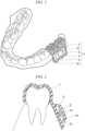
- FIG. 1 is a view showing an example of an appearance of the intraoral biological monitoring device according to the first embodiment.
- Fig. 2 is a view showing an example of a cross section in a plane passing through a sensor and a photodetector which are included in the intraoral biological monitoring device according to the first embodiment.
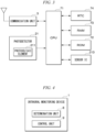
- Fig. 3 is a view showing an example of a hardware configuration of the intraoral biological monitoring device according to the first embodiment.
- an intraoral biological monitoring device 11 includes a sensor 2, a communication unit 3, a battery 4, a substrate 5, a mouthpiece 61, a central processing unit (CPU) 71, a read only memory (ROM) 72, a random access memory (RAM) 73, and a real-time clock (RTC) 74.
- CPU central processing unit
- ROM read only memory
- RAM random access memory
- RTC real-time clock
- the sensor 2 is an optical sensor including a photodetector 21 that detects light, and is disposed in a gum G of a subject.
- the sensor 2 is disposed in the gum G of the subject.
- the photodetector 21 detects the light having a wavelength belonging to a near infrared region or a visible light region.
- the light detected by the photodetector 21 may be subjected to a predetermined modulation.
- the predetermined modulation referred to herein means optionally changing a wavelength, an intensity, a timing at which an output starts, or a timing at which the output ends.
- the photodetector 21 may include a photovoltaic element 211 that receives the light to generate electric power, and may detect the light by using the electric power generated by the photovoltaic element 211.
- the sensor 2 may be controlled by a sensor integrated circuit (IC) 213 shown in Fig. 3 , and may be intermittently operated, for example, every 10 seconds.
- IC sensor integrated circuit
- the communication unit 3 performs communication, that is, advertising, in response to an operation in which a signal is input to the sensor 2. For example, the communication unit 3 performs the communication in response to an operation in which the photodetector 21 detects the light. The length of one advertising is 20 seconds, for example.
- the communication unit 3 performs the communication with an external device 100 (to be described later) in order to transmit attachment/detachment determining data acquired by the intraoral biological monitoring device 11 to the external device 100.
- the battery 4 supplies the electric power to each unit of the intraoral biological monitoring device 11.
- the substrate 5 holds the sensor 2, the communication unit 3, and the battery 4.
- the mouthpiece 61 holds the sensor 2, the communication unit 3, the battery 4, and the substrate 5, is made of a light-transmitting material, and is attached to a crown T of the subject in a state where the photodetector 21 faces at least one of the crown T and the gum G of the subject. Light transmittance of this material is preferably 20% or higher, for example.
- the mouthpiece 61 covers at least a part of the gum G of the subject.
- the mouthpiece 61 covers at least the photodetector 21 in the sensor 2. Specifically, the mouthpiece 61 seals the sensor 2 together with the communication unit 3, the battery 4, and the substrate 5.
- Fig. 4 is a view showing an example of a functional configuration of the intraoral biological monitoring device according to the first embodiment.
- the CPU 71 reads various programs stored in the read only memory (ROM) 72 when necessary, deploys various programs in the random access memory (RAM) 73, and executes various programs to function as the determination unit 8 and the control unit 9 which are shown in Fig. 4 .
- the RTC 74 activates the CPU 71 which is normally in a sleep state, when necessary.
- the determination unit 8 determines that the mouthpiece 61 is attached to the crown T of the subject, when the sensor 2 does not detect the light, and determines that the mouthpiece 61 is not attached to the crown T of the subject, when the sensor 2 detects the light.
- the control unit 9 controls an operation of each unit of the intraoral biological monitoring device 11, for example, the sensor 2 and the communication unit 3, when necessary.
- FIG. 5 is a sequence diagram showing an example of a process performed by the intraoral biological monitoring device and the external device according to the first embodiment.
- Fig. 5 shows an example of a process performed when the intraoral biological monitoring device 11 transmits the attachment/detachment determining data acquired by an attachment/detachment determining sensor (not shown) to the external device 100.
- the attachment/detachment determining sensor is an optical sensor or a temperature sensor, for example.
- the attachment/detachment determining sensor is an optical sensor
- the period during which the optical sensor does not detect light corresponds to the period during which the intraoral biological monitoring device 11 is attached to the crown T of the subject.
- a period during which the optical sensor detects the light corresponds to a period during which the intraoral biological monitoring device 11 is not attached to the crown T of the subject.
- a period during which a temperature detected by the temperature sensor is approximately the same as a body temperature of the subject corresponds to a period during which the intraoral biological monitoring device 11 is attached to the crown T of the subject.
- a period during which the temperature detected by the temperature sensor is different from the body temperature of the subject by a prescribed temperature or higher corresponds to a period during which the intraoral biological monitoring device 11 is not attached to the crown T of the subject.
- the external device 100 is a computer used by a doctor. Based on data acquireed by the attachment/detachment determining sensor, the external device 100 estimates the period during which the intraoral biological monitoring device 11 is attached to the crown T of the subject and the period during which the intraoral biological monitoring device 11 is not attached to the crown T of the subject.
- the external device 100 includes a communication unit 300, a control unit 900, and a light emitting unit 2100.
- the communication unit 300 performs the communication with the intraoral biological monitoring device 11.
- the control unit 900 controls an operation of each unit of the external device 100, when necessary. Under the control of the control unit 900, the light emitting unit 2100 outputs the light subjected to the above-described predetermined modulation, to the photodetector 21.
- Step S101 the control unit 900 transmits a light emitting start signal instructing the light emitting unit 2100 to start light emitting to the light emitting unit 2100.
- the control unit 900 transmits the light emitting start signal to the light emitting unit 2100, when a switch provided in the external device 100 is operated or a request is made from a program installed in the external device 100.
- Step S102 the light emitting unit 2100 starts light emitting.
- Step S103 the photodetector 21 starts light detection.
- Step S104 the light emitting unit 2100 ends the light emitting.
- a time from a start to an end of the light emitting of the light emitting unit 2100 is set in advance.
- Step S105 the photodetector 21 ends the light detection.
- Step S106 the photodetector 21 transmits a light detection signal indicating that the light is detected, to the control unit 9.
- Step S107 the control unit 9 transmits an advertising start signal instructing the communication unit 3 to start advertising, to the communication unit 3.
- Step S108 the communication unit 3 transmits an advertising packet to the communication unit 300.
- Step S109 the communication unit 300 receives the advertising packet from the communication unit 3.
- Step S110 the communication unit 300 notifies the control unit 900 that the advertising packet is received.
- Step S111 the control unit 900 transmits a connection performing signal instructing to the communication unit 3 to transmit a connection request signal requesting the intraoral biological monitoring device 11 for communication connection, to the communication unit 3.
- Step S112 the communication unit 300 transmits the connection request signal to the communication unit 3.
- Step S113 the communication unit 3 transfers the connection request signal received from the communication unit 300 to the control unit 9.
- Step S114 the control unit 9 causes the communication unit 3 to establish the communication connection with the external device 100.
- Step S115 the communication unit 3 transmits a data reception request signal requesting the external device 100 to receive attachment/detachment determining data to the communication unit 300.
- Step S116 the communication unit 300 transmits a data transmission permission signal permitting the transmission of attachment/detachment determining data to the intraoral biological monitoring device 11.
- Step S 117 the communication unit 3 transmits the attachment/detachment determining data to the communication unit 300.
- Step S118 the communication unit 300 receives the attachment/detachment determining data from the communication unit 3.
- Step S119 the communication unit 3 transmits a data transmission end signal indicating that the attachment/detachment determining data is completely transmitted to the external device 100, to the control unit 9.
- Step S120 the control unit 9 transmits a communication end signal instructing the communication unit 3 to end the communication with the external device 100.
- Step S121 the communication unit 3 ends the communication with the external device 100.
- the intraoral biological monitoring device 11 performs the communication with the external device 100 in response to an operation in which a signal is input to the sensor 2. Therefore, the intraoral biological monitoring device 11 does not require a switch for switching between a case where the advertising is performed and a case where the advertising is not performed. Accordingly, a size increase can be avoided.
- the intraoral biological monitoring device 11 can perform the advertising only when necessary.
- the intraoral biological monitoring device 11 can avoid the electric power stored in the battery 4 from being wasted by performing the advertising more than necessary. Accordingly, the size increase caused by an increase in size of the battery 4 can be avoided.
- the intraoral biological monitoring device 11 adopts the optical sensor including the photodetector 21 made of a light-transmitting material and covered with the mouthpiece 61.
- the sensor 2 is smaller than the switch for switching between a case where the advertising is performed and a case where the advertising is not performed. Therefore, the intraoral biological monitoring device 11 can perform the advertising simply by inputting the light to the photodetector 21 while avoiding the size increase.
- the mouthpiece 61 is attached to the crown T of the subject in a state where the photodetector 21 faces at least one of the crown T and the gum G of the subject.
- the intraoral biological monitoring device 11 is attached to the crown T of the subject. It is possible to avoid a situation in which the advertising is unnecessarily performed since the light is input to the photodetector 21 when the subject opens his or her mouth. Simultaneously, the intraoral biological monitoring device 11 can perform the advertising by inputting the light to the photodetector 21 only when the intraoral biological monitoring device 11 performs the communication with the external device 100 after being detached from the crown T of the subject.
- the photodetector 21 detects the light having a wavelength belonging to the near infrared region of the visible light region. In this manner, the intraoral biological monitoring device 11 avoids a situation in which an oral cavity of the subject is irradiated with ultraviolet rays that may adversely affect a human body, and dental materials used for treatment of the oral cavity of the subject can be more widely selected.
- the photodetector 21 detects the light subjected to a predetermined modulation. In this manner, the intraoral biological monitoring device 11 can avoid a situation in which the advertising is unnecessarily performed due to disturbance of the light input to the photodetector 21 when the subject opens his or her mouth.
- the photodetector 21 includes a photovoltaic element that receives the light to generate electric power, and detects the light by using the electric power generated by the photovoltaic element. In this manner, the intraoral biological monitoring device 11 can less rely on the battery 4 for the electric power required for the advertising, and can save the electric power stored in the battery 4.
- the senor 2 is intermittently operated, for example, every 10 seconds. In this manner, the intraoral biological monitoring device 11 can reduce the electric power consumed by the sensor 2, and can save the electric power stored in the battery 4.
- the intraoral biological monitoring device 11 includes the determination unit 8 for determining that the mouthpiece 61 is attached to the crown T of the subject, when the sensor 2 does not detect the light, and determining that the mouthpiece 61 is not attached to the crown T of the subject, when the sensor 2 detects the light.
- the intraoral biological monitoring device 11 can omit the attachment/detachment determining sensor for acquiring the attachment/detachment determining data, and can avoid a size increase.
- the intraoral biological monitoring device 11 can complexly and accurately determine whether or not the intraoral biological monitoring device 11 itself is attached to the crown T of the subject.
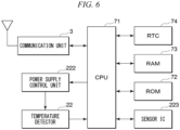
- FIG. 6 is a view showing an example of a hardware configuration of the intraoral biological monitoring device according to the second embodiment.
- An intraoral biological monitoring device 12 according to the second embodiment includes a sensor including a temperature detector 22 instead of the sensor 2 including the photodetector 21 included in the intraoral biological monitoring device 11 according to the first embodiment.
- points different from those of the intraoral biological monitoring device 11 according to the first embodiment will be mainly described, and repeated description of the first embodiment will be omitted as appropriate.
- the intraoral biological monitoring device 12 includes the sensor 2, the communication unit 3, the battery 4, the substrate 5, the mouthpiece 61, the determination unit 8, and the control unit 9 which are described above.
- the intraoral biological monitoring device 12 includes the CPU 71, the ROM 72, the RAM 73, and the RTC 74 which are shown in Fig. 6 .
- the sensor 2 included in the intraoral biological monitoring device 12 is a temperature sensor including the temperature detector 22 that detects a temperature.
- the communication unit 3 performs the communication in response to an operation in which the temperature detector 22 detects a temperature rise equal to or greater than a predetermined first threshold value.
- the predetermined threshold value is a temperature of 150 degrees Celsius or higher, and 60 degrees Celsius.
- the temperature of 150 degrees Celsius or higher referred to herein is an example of a temperature at which the temperature detector 22 fails due to a high temperature.
- the temperature of 60 degrees Celsius referred to herein is an example of a temperature which is sufficiently higher than the body temperature of the subject and is relatively easily raised.
- the temperature detector 22 is covered with the mouthpiece 61 made of a light-transmitting material.
- the communication unit 3 performs the communication in response to an operation in which the temperature detector 22 detects a temperature rise equal to or greater than the predetermined first threshold value when the temperature detector 22 is irradiated with the light.
- the sensor 2 may be controlled by a sensor IC 223 shown in Fig. 6 , and may be intermittently operated. Furthermore, the electric power supplied to the temperature detector 22 may be controlled by a power supply control unit 222 shown in Fig. 6 .
- the determination unit 8 determines that the mouthpiece 61 is attached to the crown T of the subject, when the sensor 2 detects a temperature equal to or greater than a predetermined second threshold value, and determines that the mouthpiece 61 is not attached to the crown T of the subject, when the sensor 2 detects a temperature smaller than the predetermined second threshold value.
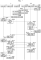
- Fig. 7 is a sequence diagram showing an example of a process performed by the intraoral biological monitoring device and the external device according to the second embodiment.
- Step 201 and Step S202, Step S204, and Step S207 to Step S221 which are shown in Fig. 7 are the same as Step 101 and Step S102, Step S104, and Step S107 to Step S121 which are shown in Fig. 5 . Therefore, in the following description, Step S203, Step S205, and Step S206 will be described.
- Step S204 the temperature detector 22 starts temperature detection.
- Step S206 the temperature detector 22 ends the temperature detection.
- Step S207 the temperature detector 22 transmits a temperature detection signal indicating that the temperature is detected, to the control unit 9.
- the intraoral biological monitoring device 12 performs the communication with the external device 100 in response to an operation in which a signal is input to the sensor 2. Therefore, the intraoral biological monitoring device 12 does not require a switch for switching between a case where the advertising is performed and a case where the advertising is not performed. Accordingly, a size increase can be avoided.
- the intraoral biological monitoring device 12 can perform the advertising only when necessary.
- the intraoral biological monitoring device 12 can avoid the electric power stored in the battery 4 from being wasted by performing the advertising more than necessary. Accordingly, the size increase caused by an increase in size of the battery 4 can be avoided.
- the intraoral biological monitoring device 12 adopts the temperature sensor including the temperature detector 22, and performs the communication in response to an operation in which the temperature detector 22 detects a temperature rise equal to or greater than the predetermined first threshold value.
- the sensor 2 is smaller than the switch for switching between a case where the advertising is performed and a case where the advertising is not performed. Therefore, the intraoral biological monitoring device 12 can perform the advertising simply by inputting the light or heat to the temperature detector 22 and increasing the temperature while avoiding the size increase.
- the communication unit 3 adopts the temperature of 60 degrees Celsius, as the predetermined first threshold value. In this manner, the intraoral biological monitoring device 12 can avoid a situation in which the communication unit 3 unnecessarily performs the advertising in response to an operation in which the temperature detector 22 detects the temperature rise caused by the body temperature of the subject.
- the communication unit 3 adopts the temperature of 150 degrees Celsius or higher, as the predetermined first threshold value.
- the intraoral biological monitoring device 12 can avoid a situation in which the communication unit 3 unnecessarily performs the advertising in response to an operation in which the temperature detector 22 detects the temperature rise caused by the body temperature of the subject.
- the mouthpiece 61 is used for orthodontics, in many cases, it is premised as follows in the intraoral biological monitoring device 12. The attachment/detachment determining data is discarded as it is after the attachment/detachment determining data is acquired for a certain period of time. In this case, there is no particular problem even when the temperature detector 22 fails due to a high temperature.
- the intraoral biological monitoring device 12 performs the communication in response to an operation in which the temperature detector 22 detects a temperature rise equal to or greater than the predetermined first threshold value when the temperature detector 22 covered with the mouthpiece 61 made of a light-transmitting material is irradiated with the light. Therefore, the intraoral biological monitoring device 12 can avoid a situation in which a part other than the temperature detector 22 is damaged due to the heat by using the light to locally heat the temperature detector 22.
- the sensor 2 is intermittently operated. In this manner, the intraoral biological monitoring device 12 can reduce the electric power consumed by the sensor 2, and can save the electric power stored in the battery 4.
- the intraoral biological monitoring device 12 includes the determination unit 8 for determining that the mouthpiece is attached to the crown T of the subject, when the sensor 2 detects a temperature equal to or greater than the predetermined second threshold value, and determining that the mouthpiece 61 is not attached to the crown T of the subject, when the sensor 2 detects a temperature smaller than the predetermined second threshold value.
- the intraoral biological monitoring device 12 can omit the attachment/detachment determining sensor for acquiring the attachment/detachment determining data, and can avoid a size increase.
- the intraoral biological monitoring device 11 can complexly and accurately determine whether or not the intraoral biological monitoring device 11 itself is attached to the crown T of the subject.
- Fig. 8 is a view showing an example of a cross section in a plane passing through a sensor and a photodetector which are included in an intraoral biological monitoring device according to another embodiment.
- the sensor 2 may be disposed in the crown T and the gum G of the subject.
- the intraoral biological monitoring device 11 according to the first embodiment and the intraoral biological monitoring device 12 according to the second embodiment include a mouthpiece 62 shown in Fig. 8 instead of the mouthpiece 61 described above.
- Fig. 9 is a view showing an example of a cross section in a plane passing through a sensor and a photodetector which are included in an intraoral biological monitoring device according to another embodiment.
- the sensor 2 may be disposed in the crown T of the subject.
- the intraoral biological monitoring device 11 and the intraoral biological monitoring device 12 include a mouthpiece 63 shown in Fig. 9 instead of the mouthpiece 61 described above.
- the sensor 2 is disposed in at least one of a part of the crown T of the subject which does not come into contact with other teeth and the gum G of the subject, even when the subject occludes a tooth of an upper jaw and a tooth of a lower jaw.
- the intraoral biological monitoring device 11 according to the first embodiment and the intraoral biological monitoring device 12 according to the second embodiment can avoid a situation in which occlusion of the subject is affected.
- Fig. 10 is a view showing an example of a cross section in a plane passing through a sensor and a photodetector which are included in an intraoral biological monitoring device according to another embodiment.
- the mouthpiece 61 may be attached to the crown T of the subject in a state where the sensor 2 faces a direction different from a direction in which the crown T and the gum G of the subject are present.
- the photodetector 21 or the temperature detector 22 may be in a state of facing a direction different from the direction in which the crown T and the gum G of the subject are present. In this manner, the intraoral biological monitoring device 11 or the intraoral biological monitoring device 12 can perform the advertising in response to an operation in which the light or the temperature rise is detected, even when the mouthpiece 61 is attached to the crown T of the subject.
- the intraoral biological monitoring device 12 may include a light-absorbent member 215 provided in a region irradiated with the light to absorb the light.
- the light-absorbent member 215 is made of a material containing carbon, and is attached to the substrate 5 to surround the temperature detector 22. In this manner, the intraoral biological monitoring device 12 can efficiently convert light irradiation into heat, and can perform the communication in response to an operation in which a temperature rise equal to or greater than the predetermined first threshold value is detected.
- the mouthpiece 61 may only cover a part of the sensor 2.
- the mouthpiece 61 may cover a part except for a part where the photodetector 21 or the temperature detector 22 fetches the light.
- the whole mouthpiece 61 is made of the light-transmitting material.
- the present invention is not limited thereto.
- the mouthpiece 61 may be made of a material which does not transmit the light, except for a part where the photodetector 21 or the temperature detector 22 fetches the light.
- the sensor 2 includes the temperature detector 22 and the temperature detector 22 detects the temperature rise caused by heating instead of the temperature rise caused by light irradiation
- the whole mouthpiece 61 may be made of a material which does not transmit the light.
- the intraoral biological monitoring device 11 and the intraoral biological monitoring device 12 include the CPU 71, the ROM 72, and the RAM 73 has been described as an example.
- the present invention is not limited thereto.
- the intraoral biological monitoring device 11 and the intraoral biological monitoring device 12 may include a microcomputer having the three functions instead of the CPU 71, the ROM 72, and the RAM 73.
- the intraoral biological monitoring device 11 and the intraoral biological monitoring device 12 include the CPU 71, the ROM 72, the RAM 73, the RTC 74, and the communication unit 3 has been described as an example.
- the present invention is not limited thereto.
- the intraoral biological monitoring device 11 and the intraoral biological monitoring device 12 may include a microcomputer having the five functions instead of the CPU 71, the ROM 72, the RAM 73, the RTC 74, and the communication unit 3.
- the external device 100 irradiates the temperature detector 22 with the light by using the light emitting unit 2100
- the present invention is not limited thereto.
- the external device 100 may include a heat generating unit having a heat source such as a heating wire instead of the light emitting unit 2100, and the temperature detector 22 may be heated by using the heat generating unit.
- the functions included in the above-described intraoral biological monitoring device 11 may be entirely or partially recorded as a program on a computer-readable recording medium, and the program may be executed by a computer system.
- the computer system includes hardware such as a peripheral device.
- the computer-readable recording medium includes a portable medium such as a flexible disk, a magneto-optical disk, a ROM, and a CD-ROM, a storage device such as a hard disk incorporated in the computer system, or a RAM included in a server on a network such as the Internet.
- a volatile memory is an example of a recording medium that holds a program for a certain period of time.
- the above-described program may be transmitted to another computer system by a transmission medium, for example, a network such as the Internet or a communication line such as a telephone line.
- a transmission medium for example, a network such as the Internet or a communication line such as a telephone line.
- the above-described program may be a program that entirely or partially realizes the above-described functions.
- the program that partially realizes the above-described functions may be a program that can realize the above-described functions in combination with a program recorded in advance in the computer system, that is, a so-called difference program.
Landscapes
- Health & Medical Sciences (AREA)
- Life Sciences & Earth Sciences (AREA)
- Engineering & Computer Science (AREA)
- Physics & Mathematics (AREA)
- Public Health (AREA)
- Biomedical Technology (AREA)
- General Health & Medical Sciences (AREA)
- Animal Behavior & Ethology (AREA)
- Veterinary Medicine (AREA)
- Medical Informatics (AREA)
- Biophysics (AREA)
- Molecular Biology (AREA)
- Surgery (AREA)
- Heart & Thoracic Surgery (AREA)
- Pathology (AREA)
- Dentistry (AREA)
- Oral & Maxillofacial Surgery (AREA)
- General Physics & Mathematics (AREA)
- Epidemiology (AREA)
- Computer Networks & Wireless Communication (AREA)
- Audiology, Speech & Language Pathology (AREA)
- General Business, Economics & Management (AREA)
- Primary Health Care (AREA)
- Optics & Photonics (AREA)
- Business, Economics & Management (AREA)
- Spectroscopy & Molecular Physics (AREA)
- Measuring And Recording Apparatus For Diagnosis (AREA)
- Dental Tools And Instruments Or Auxiliary Dental Instruments (AREA)
- Measuring Temperature Or Quantity Of Heat (AREA)
- Endoscopes (AREA)
Description
- The present invention relates to an intraoral biological monitoring device.
- Currently, a technique to perform various treatments has been established in which a mouthpiece or the like for holding a sensor is worn in an oral cavity of a subject to acquire biological data from the subject. For example, PTL 1 discloses an intraoral-installed biological monitor including a biological sensor, a signal processing unit, a communication unit, and an operating equipment unit. The biological sensor is attached to a denture base or a mouthpiece and includes a sensor that detects a body temperature, a pulse, and enzymes or metabolites or the like in saliva, and an acceleration sensor that detects a body posture or a movement. The signal processing unit evaluates data obtained from the biological sensor, detects an abnormal value, and stores the data. The communication unit uses a wireless system to transmit the data in the signal processing unit to a management center such as a medical center, and to receive a command signal from the management center such as the medical center. The operating equipment unit is operated, based on a command signal from the management center.
- [PTL 1]
Japanese Unexamined Patent Application, First Publication No. 2004-167120 -
US 2018/000563 discloses intraoral appliances with sensing for detection of placement of dental aligners in a patient's mouth on teeth for indication of wearing compliance. The disclosed apparatuses and methods are for detecting wearing, including compliance, and for reliably transferring data, by wired or wireless direct or indirect communication of electronic compliance information to a smartphone. Also described are dental appliances that can detect physiological parameters related to respiration and sleep. Also described are aligner cases that enable NFC communication with electronic compliance indicator (ECI) devices and Bluetooth communication with smartphones. - The intraoral-installed biological monitor configured in this way is usually sealed in the denture base or the mouthpiece. Accordingly, it is necessary to transmit acquired data to an external device such as a computer used by a doctor with wireless communication such as Bluetooth (registered trademark) Low Energy (BLE). For example, the data referred to herein is biological data acquired while being attached to a crown of a subject, and attachment/detachment determining data which is a basis for determining whether or not the intraoral-installed biological monitor itself is installed in an oral cavity of the subject.
- However, when the above-described intraoral-installed biological monitor adopts the wireless communication such as the BLE, the acquired data cannot be transmitted to the external device unless the acquired data is advertised to the external device. On the other hand, the intraoral-installed biological monitor consumes a large amount of electric power due to the advertising. Therefore, it is preferable to perform the advertising only when the acquired data is transmitted to the external device.
- However, in many cases, the intraoral-installed biological monitor is miniaturized in view of a fact that the intraoral-installed biological monitor is installed to be in the intraoral of the subject. Therefore, in the intraoral-placed biological monitor, it is difficult to be switched between a case where advertising is performed and a case where advertising is not performed, and it is difficult to receive power used for the advertising from a large capacity battery.
- The present invention is made in view of the above-described problems, and an object thereof is to provide an intraoral biological monitoring device capable of performing advertising when necessary while avoiding a size increase.
- According to an aspect of the present invention, in order to achieve the above-described object, there is provided an intraoral biological monitoring device as defined in claim 1.
- An intraoral biological monitoring device according to another aspect of the present invention is defined in claim 7.
- According to the present invention, advertising can be performed when necessary while avoiding a size increase.
-
-
Fig. 1 is a view showing an example of an appearance of an intraoral biological monitoring device according to a first embodiment. -
Fig. 2 is a view showing an example of a cross section in a plane passing through a sensor and a photodetector which are included in the intraoral biological monitoring device according to the first embodiment. -
Fig. 3 is a view showing an example of a hardware configuration of the intraoral biological monitoring device according to the first embodiment. -
Fig. 4 is a view showing an example of a functional configuration of the intraoral biological monitoring device according to the first embodiment. -
Fig. 5 is a sequence diagram showing an example of a process performed by the intraoral biological monitoring device and an external device according to the first embodiment. -
Fig. 6 is a view showing an example of a hardware configuration of an intraoral biological monitoring device according to a second embodiment. -
Fig. 7 is a sequence diagram showing an example of a process performed by the intraoral biological monitoring device and an external device according to the second embodiment. -
Fig. 8 is a view showing an example of a cross section in a plane passing through a sensor and a photodetector which are included in an intraoral biological monitoring device according to another embodiment. -
Fig. 9 is a view showing an example of a cross section in a plane passing through a sensor and a photodetector which are included in an intraoral biological monitoring device according to another embodiment. -
Fig. 10 is a view showing an example of a cross section in a plane passing through a sensor and a photodetector which are included in an intraoral biological monitoring device according to another embodiment. - An example of an intraoral biological monitoring device according to a first embodiment will be described with reference to
Figs. 1 to 4 .Fig. 1 is a view showing an example of an appearance of the intraoral biological monitoring device according to the first embodiment.Fig. 2 is a view showing an example of a cross section in a plane passing through a sensor and a photodetector which are included in the intraoral biological monitoring device according to the first embodiment.Fig. 3 is a view showing an example of a hardware configuration of the intraoral biological monitoring device according to the first embodiment. - As shown in
Figs. 1, 2 , and3 , an intraoralbiological monitoring device 11 includes asensor 2, acommunication unit 3, abattery 4, asubstrate 5, amouthpiece 61, a central processing unit (CPU) 71, a read only memory (ROM) 72, a random access memory (RAM) 73, and a real-time clock (RTC) 74. - The
sensor 2 is an optical sensor including aphotodetector 21 that detects light, and is disposed in a gum G of a subject. Thesensor 2 is disposed in the gum G of the subject. For example, thephotodetector 21 detects the light having a wavelength belonging to a near infrared region or a visible light region. The light detected by thephotodetector 21 may be subjected to a predetermined modulation. The predetermined modulation referred to herein means optionally changing a wavelength, an intensity, a timing at which an output starts, or a timing at which the output ends. Furthermore, thephotodetector 21 may include aphotovoltaic element 211 that receives the light to generate electric power, and may detect the light by using the electric power generated by thephotovoltaic element 211. Thesensor 2 may be controlled by a sensor integrated circuit (IC) 213 shown inFig. 3 , and may be intermittently operated, for example, every 10 seconds. - The
communication unit 3 performs communication, that is, advertising, in response to an operation in which a signal is input to thesensor 2. For example, thecommunication unit 3 performs the communication in response to an operation in which thephotodetector 21 detects the light. The length of one advertising is 20 seconds, for example. Thecommunication unit 3 performs the communication with an external device 100 (to be described later) in order to transmit attachment/detachment determining data acquired by the intraoralbiological monitoring device 11 to theexternal device 100. Thebattery 4 supplies the electric power to each unit of the intraoralbiological monitoring device 11. Thesubstrate 5 holds thesensor 2, thecommunication unit 3, and thebattery 4. - The
mouthpiece 61 holds thesensor 2, thecommunication unit 3, thebattery 4, and thesubstrate 5, is made of a light-transmitting material, and is attached to a crown T of the subject in a state where thephotodetector 21 faces at least one of the crown T and the gum G of the subject. Light transmittance of this material is preferably 20% or higher, for example. Themouthpiece 61 covers at least a part of the gum G of the subject. Furthermore, themouthpiece 61 covers at least thephotodetector 21 in thesensor 2. Specifically, themouthpiece 61 seals thesensor 2 together with thecommunication unit 3, thebattery 4, and thesubstrate 5. -
Fig. 4 is a view showing an example of a functional configuration of the intraoral biological monitoring device according to the first embodiment. TheCPU 71 reads various programs stored in the read only memory (ROM) 72 when necessary, deploys various programs in the random access memory (RAM) 73, and executes various programs to function as thedetermination unit 8 and the control unit 9 which are shown inFig. 4 . TheRTC 74 activates theCPU 71 which is normally in a sleep state, when necessary. - The
determination unit 8 determines that themouthpiece 61 is attached to the crown T of the subject, when thesensor 2 does not detect the light, and determines that themouthpiece 61 is not attached to the crown T of the subject, when thesensor 2 detects the light. The control unit 9 controls an operation of each unit of the intraoralbiological monitoring device 11, for example, thesensor 2 and thecommunication unit 3, when necessary. - Next, an example of an operation of the intraoral
biological monitoring device 11 according to the first embodiment will be described with reference toFig. 5. Fig. 5 is a sequence diagram showing an example of a process performed by the intraoral biological monitoring device and the external device according to the first embodiment. -
Fig. 5 shows an example of a process performed when the intraoralbiological monitoring device 11 transmits the attachment/detachment determining data acquired by an attachment/detachment determining sensor (not shown) to theexternal device 100. The attachment/detachment determining sensor is an optical sensor or a temperature sensor, for example. - For example, when the attachment/detachment determining sensor is an optical sensor, the period during which the optical sensor does not detect light corresponds to the period during which the intraoral
biological monitoring device 11 is attached to the crown T of the subject. On the other hand, a period during which the optical sensor detects the light corresponds to a period during which the intraoralbiological monitoring device 11 is not attached to the crown T of the subject. - Alternatively, when the attachment/detachment determining sensor is the temperature sensor, a period during which a temperature detected by the temperature sensor is approximately the same as a body temperature of the subject corresponds to a period during which the intraoral
biological monitoring device 11 is attached to the crown T of the subject. On the other hand, a period during which the temperature detected by the temperature sensor is different from the body temperature of the subject by a prescribed temperature or higher corresponds to a period during which the intraoralbiological monitoring device 11 is not attached to the crown T of the subject. - For example, the
external device 100 is a computer used by a doctor. Based on data acquireed by the attachment/detachment determining sensor, theexternal device 100 estimates the period during which the intraoralbiological monitoring device 11 is attached to the crown T of the subject and the period during which the intraoralbiological monitoring device 11 is not attached to the crown T of the subject. Theexternal device 100 includes acommunication unit 300, acontrol unit 900, and alight emitting unit 2100. - The
communication unit 300 performs the communication with the intraoralbiological monitoring device 11. Thecontrol unit 900 controls an operation of each unit of theexternal device 100, when necessary. Under the control of thecontrol unit 900, thelight emitting unit 2100 outputs the light subjected to the above-described predetermined modulation, to thephotodetector 21. - In Step S101, the
control unit 900 transmits a light emitting start signal instructing thelight emitting unit 2100 to start light emitting to thelight emitting unit 2100. For example, thecontrol unit 900 transmits the light emitting start signal to thelight emitting unit 2100, when a switch provided in theexternal device 100 is operated or a request is made from a program installed in theexternal device 100. - In Step S102, the
light emitting unit 2100 starts light emitting. - In Step S103, the
photodetector 21 starts light detection. - In Step S104, the
light emitting unit 2100 ends the light emitting. A time from a start to an end of the light emitting of thelight emitting unit 2100 is set in advance. - In Step S105, the
photodetector 21 ends the light detection. - In Step S106, the
photodetector 21 transmits a light detection signal indicating that the light is detected, to the control unit 9. - In Step S107, the control unit 9 transmits an advertising start signal instructing the
communication unit 3 to start advertising, to thecommunication unit 3. - In Step S108, the
communication unit 3 transmits an advertising packet to thecommunication unit 300. - In Step S109, the
communication unit 300 receives the advertising packet from thecommunication unit 3. - In Step S110, the
communication unit 300 notifies thecontrol unit 900 that the advertising packet is received. - In Step S111, the
control unit 900 transmits a connection performing signal instructing to thecommunication unit 3 to transmit a connection request signal requesting the intraoralbiological monitoring device 11 for communication connection, to thecommunication unit 3. - In Step S112, the
communication unit 300 transmits the connection request signal to thecommunication unit 3. - In Step S113, the
communication unit 3 transfers the connection request signal received from thecommunication unit 300 to the control unit 9. - In Step S114, the control unit 9 causes the
communication unit 3 to establish the communication connection with theexternal device 100. - In Step S115, the
communication unit 3 transmits a data reception request signal requesting theexternal device 100 to receive attachment/detachment determining data to thecommunication unit 300. - In Step S116, the
communication unit 300 transmits a data transmission permission signal permitting the transmission of attachment/detachment determining data to the intraoralbiological monitoring device 11. - In Step S 117, the
communication unit 3 transmits the attachment/detachment determining data to thecommunication unit 300. - In Step S118, the
communication unit 300 receives the attachment/detachment determining data from thecommunication unit 3. - In Step S119, the
communication unit 3 transmits a data transmission end signal indicating that the attachment/detachment determining data is completely transmitted to theexternal device 100, to the control unit 9. - In Step S120, the control unit 9 transmits a communication end signal instructing the
communication unit 3 to end the communication with theexternal device 100. - In Step S121, the
communication unit 3 ends the communication with theexternal device 100. - Hitherto, the intraoral
biological monitoring device 11 according to the first embodiment has been described. The intraoralbiological monitoring device 11 performs the communication with theexternal device 100 in response to an operation in which a signal is input to thesensor 2. Therefore, the intraoralbiological monitoring device 11 does not require a switch for switching between a case where the advertising is performed and a case where the advertising is not performed. Accordingly, a size increase can be avoided. In addition, the intraoralbiological monitoring device 11 can perform the advertising only when necessary. Furthermore, the intraoralbiological monitoring device 11 can avoid the electric power stored in thebattery 4 from being wasted by performing the advertising more than necessary. Accordingly, the size increase caused by an increase in size of thebattery 4 can be avoided. - In addition, as the
sensor 2, the intraoralbiological monitoring device 11 adopts the optical sensor including thephotodetector 21 made of a light-transmitting material and covered with themouthpiece 61. Thesensor 2 is smaller than the switch for switching between a case where the advertising is performed and a case where the advertising is not performed. Therefore, the intraoralbiological monitoring device 11 can perform the advertising simply by inputting the light to thephotodetector 21 while avoiding the size increase. - In addition, the
mouthpiece 61 is attached to the crown T of the subject in a state where thephotodetector 21 faces at least one of the crown T and the gum G of the subject. In this manner, the intraoralbiological monitoring device 11 is attached to the crown T of the subject. It is possible to avoid a situation in which the advertising is unnecessarily performed since the light is input to thephotodetector 21 when the subject opens his or her mouth. Simultaneously, the intraoralbiological monitoring device 11 can perform the advertising by inputting the light to thephotodetector 21 only when the intraoralbiological monitoring device 11 performs the communication with theexternal device 100 after being detached from the crown T of the subject. - In addition, the
photodetector 21 detects the light having a wavelength belonging to the near infrared region of the visible light region. In this manner, the intraoralbiological monitoring device 11 avoids a situation in which an oral cavity of the subject is irradiated with ultraviolet rays that may adversely affect a human body, and dental materials used for treatment of the oral cavity of the subject can be more widely selected. - In addition, the
photodetector 21 detects the light subjected to a predetermined modulation. In this manner, the intraoralbiological monitoring device 11 can avoid a situation in which the advertising is unnecessarily performed due to disturbance of the light input to thephotodetector 21 when the subject opens his or her mouth. - In addition, the
photodetector 21 includes a photovoltaic element that receives the light to generate electric power, and detects the light by using the electric power generated by the photovoltaic element. In this manner, the intraoralbiological monitoring device 11 can less rely on thebattery 4 for the electric power required for the advertising, and can save the electric power stored in thebattery 4. - In addition, the
sensor 2 is intermittently operated, for example, every 10 seconds. In this manner, the intraoralbiological monitoring device 11 can reduce the electric power consumed by thesensor 2, and can save the electric power stored in thebattery 4. - In addition, the intraoral
biological monitoring device 11 includes thedetermination unit 8 for determining that themouthpiece 61 is attached to the crown T of the subject, when thesensor 2 does not detect the light, and determining that themouthpiece 61 is not attached to the crown T of the subject, when thesensor 2 detects the light. In this manner, the intraoralbiological monitoring device 11 can omit the attachment/detachment determining sensor for acquiring the attachment/detachment determining data, and can avoid a size increase. Alternatively, based on the attachment/detachment determining data acquired from both the attachment/detachment determining sensor and thesensor 2, the intraoralbiological monitoring device 11 can complexly and accurately determine whether or not the intraoralbiological monitoring device 11 itself is attached to the crown T of the subject. - An example of an intraoral biological monitoring device according to a second embodiment will be described with reference to
Fig. 6. Fig. 6 is a view showing an example of a hardware configuration of the intraoral biological monitoring device according to the second embodiment. An intraoral biological monitoring device 12 according to the second embodiment includes a sensor including atemperature detector 22 instead of thesensor 2 including thephotodetector 21 included in the intraoralbiological monitoring device 11 according to the first embodiment. In the following description, with regard to the intraoral biological monitoring device 12 according to the second embodiment, points different from those of the intraoralbiological monitoring device 11 according to the first embodiment will be mainly described, and repeated description of the first embodiment will be omitted as appropriate. - The intraoral biological monitoring device 12 includes the
sensor 2, thecommunication unit 3, thebattery 4, thesubstrate 5, themouthpiece 61, thedetermination unit 8, and the control unit 9 which are described above. In addition, the intraoral biological monitoring device 12 includes theCPU 71, theROM 72, theRAM 73, and theRTC 74 which are shown inFig. 6 . - The
sensor 2 included in the intraoral biological monitoring device 12 is a temperature sensor including thetemperature detector 22 that detects a temperature. Thecommunication unit 3 performs the communication in response to an operation in which thetemperature detector 22 detects a temperature rise equal to or greater than a predetermined first threshold value. For example, the predetermined threshold value is a temperature of 150 degrees Celsius or higher, and 60 degrees Celsius. The temperature of 150 degrees Celsius or higher referred to herein is an example of a temperature at which thetemperature detector 22 fails due to a high temperature. The temperature of 60 degrees Celsius referred to herein is an example of a temperature which is sufficiently higher than the body temperature of the subject and is relatively easily raised. - The
temperature detector 22 is covered with themouthpiece 61 made of a light-transmitting material. Thecommunication unit 3 performs the communication in response to an operation in which thetemperature detector 22 detects a temperature rise equal to or greater than the predetermined first threshold value when thetemperature detector 22 is irradiated with the light. Thesensor 2 may be controlled by asensor IC 223 shown inFig. 6 , and may be intermittently operated. Furthermore, the electric power supplied to thetemperature detector 22 may be controlled by a powersupply control unit 222 shown inFig. 6 . - The
determination unit 8 determines that themouthpiece 61 is attached to the crown T of the subject, when thesensor 2 detects a temperature equal to or greater than a predetermined second threshold value, and determines that themouthpiece 61 is not attached to the crown T of the subject, when thesensor 2 detects a temperature smaller than the predetermined second threshold value. - Next, an example of an operation of the intraoral biological monitoring device 12 according to the second embodiment will be described with reference to
Fig. 7. Fig. 7 is a sequence diagram showing an example of a process performed by the intraoral biological monitoring device and the external device according to the second embodiment. Step 201 and Step S202, Step S204, and Step S207 to Step S221 which are shown inFig. 7 are the same as Step 101 and Step S102, Step S104, and Step S107 to Step S121 which are shown inFig. 5 . Therefore, in the following description, Step S203, Step S205, and Step S206 will be described. - In Step S204, the
temperature detector 22 starts temperature detection. - In Step S206, the
temperature detector 22 ends the temperature detection. - In Step S207, the
temperature detector 22 transmits a temperature detection signal indicating that the temperature is detected, to the control unit 9. - Hitherto, the intraoral biological monitoring device 12 according to the second embodiment has been described. The intraoral biological monitoring device 12 performs the communication with the
external device 100 in response to an operation in which a signal is input to thesensor 2. Therefore, the intraoral biological monitoring device 12 does not require a switch for switching between a case where the advertising is performed and a case where the advertising is not performed. Accordingly, a size increase can be avoided. In addition, the intraoral biological monitoring device 12 can perform the advertising only when necessary. Furthermore, the intraoral biological monitoring device 12 can avoid the electric power stored in thebattery 4 from being wasted by performing the advertising more than necessary. Accordingly, the size increase caused by an increase in size of thebattery 4 can be avoided. - In addition, as the
sensor 2, the intraoral biological monitoring device 12 adopts the temperature sensor including thetemperature detector 22, and performs the communication in response to an operation in which thetemperature detector 22 detects a temperature rise equal to or greater than the predetermined first threshold value. Thesensor 2 is smaller than the switch for switching between a case where the advertising is performed and a case where the advertising is not performed. Therefore, the intraoral biological monitoring device 12 can perform the advertising simply by inputting the light or heat to thetemperature detector 22 and increasing the temperature while avoiding the size increase. - In addition, the
communication unit 3 adopts the temperature of 60 degrees Celsius, as the predetermined first threshold value. In this manner, the intraoral biological monitoring device 12 can avoid a situation in which thecommunication unit 3 unnecessarily performs the advertising in response to an operation in which thetemperature detector 22 detects the temperature rise caused by the body temperature of the subject. - In addition, the
communication unit 3 adopts the temperature of 150 degrees Celsius or higher, as the predetermined first threshold value. In this manner, the intraoral biological monitoring device 12 can avoid a situation in which thecommunication unit 3 unnecessarily performs the advertising in response to an operation in which thetemperature detector 22 detects the temperature rise caused by the body temperature of the subject. In addition, when themouthpiece 61 is used for orthodontics, in many cases, it is premised as follows in the intraoral biological monitoring device 12. The attachment/detachment determining data is discarded as it is after the attachment/detachment determining data is acquired for a certain period of time. In this case, there is no particular problem even when thetemperature detector 22 fails due to a high temperature. - In addition, the intraoral biological monitoring device 12 performs the communication in response to an operation in which the
temperature detector 22 detects a temperature rise equal to or greater than the predetermined first threshold value when thetemperature detector 22 covered with themouthpiece 61 made of a light-transmitting material is irradiated with the light. Therefore, the intraoral biological monitoring device 12 can avoid a situation in which a part other than thetemperature detector 22 is damaged due to the heat by using the light to locally heat thetemperature detector 22. - In addition, the
sensor 2 is intermittently operated. In this manner, the intraoral biological monitoring device 12 can reduce the electric power consumed by thesensor 2, and can save the electric power stored in thebattery 4. - In addition, the intraoral biological monitoring device 12 includes the
determination unit 8 for determining that the mouthpiece is attached to the crown T of the subject, when thesensor 2 detects a temperature equal to or greater than the predetermined second threshold value, and determining that themouthpiece 61 is not attached to the crown T of the subject, when thesensor 2 detects a temperature smaller than the predetermined second threshold value. In this manner, the intraoral biological monitoring device 12 can omit the attachment/detachment determining sensor for acquiring the attachment/detachment determining data, and can avoid a size increase. Alternatively, based on the attachment/detachment determining data acquired from both the attachment/detachment determining sensor and thesensor 2, the intraoralbiological monitoring device 11 can complexly and accurately determine whether or not the intraoralbiological monitoring device 11 itself is attached to the crown T of the subject. - In the first embodiment and the second embodiment which are described above, as shown in
Fig. 2 , a case where thesensor 2 is disposed in the gum G of the subject has been described as an example. However, the present invention is not limited thereto.Fig. 8 is a view showing an example of a cross section in a plane passing through a sensor and a photodetector which are included in an intraoral biological monitoring device according to another embodiment. As shown inFig. 8 , thesensor 2 may be disposed in the crown T and the gum G of the subject. In this case, the intraoralbiological monitoring device 11 according to the first embodiment and the intraoral biological monitoring device 12 according to the second embodiment include amouthpiece 62 shown inFig. 8 instead of themouthpiece 61 described above. -
Fig. 9 is a view showing an example of a cross section in a plane passing through a sensor and a photodetector which are included in an intraoral biological monitoring device according to another embodiment. As shown inFig. 9 , thesensor 2 may be disposed in the crown T of the subject. In this case, the intraoralbiological monitoring device 11 and the intraoral biological monitoring device 12 include amouthpiece 63 shown inFig. 9 instead of themouthpiece 61 described above. - That is, the
sensor 2 is disposed in at least one of a part of the crown T of the subject which does not come into contact with other teeth and the gum G of the subject, even when the subject occludes a tooth of an upper jaw and a tooth of a lower jaw. In this manner, the intraoralbiological monitoring device 11 according to the first embodiment and the intraoral biological monitoring device 12 according to the second embodiment can avoid a situation in which occlusion of the subject is affected. - In addition, in the first embodiment described above, as shown in
Fig. 2 , a case where themouthpiece 61 is attached to the crown T of the subject in a state where thephotodetector 21 faces at least one of the crown T and the gum G of the subject has been described as an example. However, the present invention is not limited thereto.Fig. 10 is a view showing an example of a cross section in a plane passing through a sensor and a photodetector which are included in an intraoral biological monitoring device according to another embodiment. As shown inFig. 10 , themouthpiece 61 may be attached to the crown T of the subject in a state where thesensor 2 faces a direction different from a direction in which the crown T and the gum G of the subject are present. When thesensor 2 includes thephotodetector 21 or thetemperature detector 22, thephotodetector 21 or thetemperature detector 22 may be in a state of facing a direction different from the direction in which the crown T and the gum G of the subject are present. In this manner, the intraoralbiological monitoring device 11 or the intraoral biological monitoring device 12 can perform the advertising in response to an operation in which the light or the temperature rise is detected, even when themouthpiece 61 is attached to the crown T of the subject. - In addition, when the
sensor 2 includes thetemperature detector 22, as shown inFig. 10 , the intraoral biological monitoring device 12 may include a light-absorbent member 215 provided in a region irradiated with the light to absorb the light. For example, the light-absorbent member 215 is made of a material containing carbon, and is attached to thesubstrate 5 to surround thetemperature detector 22. In this manner, the intraoral biological monitoring device 12 can efficiently convert light irradiation into heat, and can perform the communication in response to an operation in which a temperature rise equal to or greater than the predetermined first threshold value is detected. - In addition, in the first embodiment and the second embodiment, a case where the
sensor 2 is sealed in themouthpiece 61 has been described as an example. However, the present invention is not limited thereto. For example, themouthpiece 61 may only cover a part of thesensor 2. Alternatively, themouthpiece 61 may cover a part except for a part where thephotodetector 21 or thetemperature detector 22 fetches the light. - In addition, in the first embodiment and the second embodiment, a case where the
whole mouthpiece 61 is made of the light-transmitting material has been described as an example. However, the present invention is not limited thereto. For example, themouthpiece 61 may be made of a material which does not transmit the light, except for a part where thephotodetector 21 or thetemperature detector 22 fetches the light. In addition, when thesensor 2 includes thetemperature detector 22 and thetemperature detector 22 detects the temperature rise caused by heating instead of the temperature rise caused by light irradiation, thewhole mouthpiece 61 may be made of a material which does not transmit the light. - In addition, in the first embodiment and the second embodiment, a case where the intraoral
biological monitoring device 11 and the intraoral biological monitoring device 12 include theCPU 71, theROM 72, and theRAM 73 has been described as an example. However, the present invention is not limited thereto. For example, the intraoralbiological monitoring device 11 and the intraoral biological monitoring device 12 may include a microcomputer having the three functions instead of theCPU 71, theROM 72, and theRAM 73. - Similarly, in the first embodiment and the second embodiment, a case where the intraoral
biological monitoring device 11 and the intraoral biological monitoring device 12 include theCPU 71, theROM 72, theRAM 73, theRTC 74, and thecommunication unit 3 has been described as an example. However, the present invention is not limited thereto. For example, the intraoralbiological monitoring device 11 and the intraoral biological monitoring device 12 may include a microcomputer having the five functions instead of theCPU 71, theROM 72, theRAM 73, theRTC 74, and thecommunication unit 3. - In addition, in the first embodiment and the second embodiment, a case where the
external device 100 irradiates thetemperature detector 22 with the light by using thelight emitting unit 2100 has been described as an example. However, the present invention is not limited thereto. For example, theexternal device 100 may include a heat generating unit having a heat source such as a heating wire instead of thelight emitting unit 2100, and thetemperature detector 22 may be heated by using the heat generating unit. - In addition, the functions included in the above-described intraoral
biological monitoring device 11 may be entirely or partially recorded as a program on a computer-readable recording medium, and the program may be executed by a computer system. The computer system includes hardware such as a peripheral device. In addition, for example, the computer-readable recording medium includes a portable medium such as a flexible disk, a magneto-optical disk, a ROM, and a CD-ROM, a storage device such as a hard disk incorporated in the computer system, or a RAM included in a server on a network such as the Internet. A volatile memory is an example of a recording medium that holds a program for a certain period of time. - In addition, the above-described program may be transmitted to another computer system by a transmission medium, for example, a network such as the Internet or a communication line such as a telephone line.
- In addition, the above-described program may be a program that entirely or partially realizes the above-described functions. The program that partially realizes the above-described functions may be a program that can realize the above-described functions in combination with a program recorded in advance in the computer system, that is, a so-called difference program.
- Hitherto, the embodiments of the present invention have been described with reference to the drawings. However, a specific configuration is not limited to the above-described embodiments, and includes a design change within the scope not departing from the concept of the present invention.
-
- 11, 12: Intraoral biological monitoring device
- 2: Sensor
- 21: Photodetector
- 22: Temperature detector
- 211: Photovoltaic element
- 213: Sensor IC
- 215: Light-absorbent member
- 222: Power supply control unit
- 223: Sensor IC
- 3: Communication unit
- 4: Battery
- 5: Substrate
- 61, 62, 63: Mouthpiece
- 71: CPU
- 72: RAM
- 73: ROM
- 74: RTC
- 8: Determination unit
- 9: Control unit
- 100: External device
- 300: Communication unit
- 800: Control unit
- 2100: Light emitting unit
- G: Gum
- T: Crown
Claims (10)
- An intraoral biological monitoring device (11) comprising:a sensor (2);a communication unit (3) that is configured to perform communication in response to an operation in which a signal is input to the sensor (2);a mouthpiece (61, 62, 63) that holds the sensor (2) and the communication unit (3), and is configured to be attached to a crown (T) of a subject, and covers at least a part of a gum (G) of the subject; anda determination unit (8),wherein the sensor (2) is an optical sensor including a photodetector (21) that is configured to detect light,the mouthpiece (61, 62, 63) is made of a light-transmitting material, and covers at least the photodetector (21) of the sensor (2), andthe communication unit (3) is configured to perform the communication in response to an operation in which the light is detected by the photodetector (21),characterized in thatthe photodetector (21) is configured to face at least one of the crown (T) and the gum (G) of the subject by attachment of the mouthpiece (61, 62, 63) to the crown (T) of the subject, andthe determination unit (8) is configured to determine that the mouthpiece (61, 62, 63) is attached to the crown (T) of the subject when the sensor (2) does not detect the light, and to determine that the mouthpiece (61, 62, 63) is not attached to the crown (T) of the subject when the sensor (2) detects the light.
- The intraoral biological monitoring device (11) according to claim 1,
wherein the sensor (2) is disposed in at least one of a part of the crown (T) of the subject which does not come into contact with other teeth, even when the subject occludes a tooth of an upper jaw and a tooth of a lower jaw, and the gum (G) of the subject. - The intraoral biological monitoring device (11) according to claim 1 or 2,
wherein the photodetector (21) is configured to detect the light having a wavelength belonging to a near infrared region or a visible light region. - The intraoral biological monitoring device (11) according to any one of claims 1 to 3,
wherein the photodetector (21) is configured to detect the light subjected to predetermined modulation. - The intraoral biological monitoring device (11) according to claim 1,
wherein the photodetector (21) includes a photovoltaic element (211) that is configured to receive the light to generate electric power, and to detect the light by using the electric power generated by the photovoltaic element (211). - The intraoral biological monitoring device (11) according to any one of claims 1 to 5,
wherein the sensor (2) is intermittently operated. - An intraoral biological monitoring device (11) comprising:a sensor (2);a communication unit (3) that is configured to perform communication in response to an operation in which a signal is input to the sensor (2);a mouthpiece (61, 62, 63) that holds the sensor (2) and the communication unit (3), and is configured to be attached to a crown (T) of a subject, and covers at least a part of a gum (G) of the subject;a light-absorbent member (215), anda determination unit (8),wherein the sensor (2) is a temperature sensor including a temperature detector (22) that is configured to detect a temperature,the communication unit (3) is configured to perform the communication in response to an operation in which the temperature detector (22) detects a temperature rise equal to or greater than a predetermined first threshold value,wherein the mouthpiece (61, 62, 63) is made of a light-transmitting material, and covers at least the temperature detector (22) in the sensor (2), andwherein the determination unit (8) is configured to determine that the mouthpiece (61, 62, 63) is attached to the crown (T) of the subject when the sensor (2) detects a temperature equal to or greater than a predetermined second threshold value, and to determine that the mouthpiece (61, 62, 63) is not attached to the crown (T) of the subject when the sensor (2) detects a temperature smaller than the predetermined second threshold value,characterized in thatthe light-absorbent member (215) is provided in a region irradiated with light to absorb the light,wherein the communication unit (3) is configured to perform the communication in response to an operation in which the temperature detector (22) detects a temperature rise equal to or greater than the predetermined first threshold value when the temperature detector (22) is irradiated with the light.
- The intraoral biological monitoring device (11) according to claim 7,
wherein the communication unit (3) is configured to adopt a temperature of 60 degrees Celsius, as the predetermined first threshold value. - The intraoral biological monitoring device (11) according to claim 7,
wherein the communication unit (3) is configured to adopt a temperature of 150 degrees Celsius or higher, as the predetermined first threshold value. - The intraoral biological monitoring device (11) according to any one of claims 7 to 9, wherein the sensor (2) is intermittently operated.
Applications Claiming Priority (2)
| Application Number | Priority Date | Filing Date | Title |
|---|---|---|---|
| JP2019039436A JP7329338B2 (en) | 2019-03-05 | 2019-03-05 | Oral biomonitoring device |
| PCT/JP2020/002562 WO2020179277A1 (en) | 2019-03-05 | 2020-01-24 | Intraoral organism monitoring device |
Publications (3)
| Publication Number | Publication Date |
|---|---|
| EP3904850A1 EP3904850A1 (en) | 2021-11-03 |
| EP3904850A4 EP3904850A4 (en) | 2022-09-14 |
| EP3904850B1 true EP3904850B1 (en) | 2024-09-18 |
Family
ID=72336957
Family Applications (1)
| Application Number | Title | Priority Date | Filing Date |
|---|---|---|---|
| EP20766584.5A Active EP3904850B1 (en) | 2019-03-05 | 2020-01-24 | Intraoral organism monitoring device |
Country Status (5)
| Country | Link |
|---|---|
| US (1) | US20220104767A1 (en) |
| EP (1) | EP3904850B1 (en) |
| JP (1) | JP7329338B2 (en) |
| CN (1) | CN113874692A (en) |
| WO (1) | WO2020179277A1 (en) |
Families Citing this family (9)
| Publication number | Priority date | Publication date | Assignee | Title |
|---|---|---|---|---|
| US11478343B2 (en) * | 2017-12-06 | 2022-10-25 | Seungki MIN | Apparatus configured to be attachable and detachable to and from oral cavity |
| JP2022057582A (en) * | 2020-09-30 | 2022-04-11 | セイコーホールディングス株式会社 | Oral cavity monitoring device |
| JP7548764B2 (en) * | 2020-09-30 | 2024-09-10 | セイコーグループ株式会社 | Biometric monitoring equipment |
| JP7554625B2 (en) | 2020-09-30 | 2024-09-20 | セイコーグループ株式会社 | Biometric monitoring equipment |
| JP2022057616A (en) * | 2020-09-30 | 2022-04-11 | セイコーホールディングス株式会社 | Oral cavity monitoring device |
| JP7730117B2 (en) | 2021-09-01 | 2025-08-27 | セイコーグループ株式会社 | Biological monitoring devices |
| WO2023181741A1 (en) * | 2022-03-23 | 2023-09-28 | ソニーセミコンダクタソリューションズ株式会社 | Sensor module, mouthpiece-type device, and system |
| US20230355146A1 (en) * | 2022-05-06 | 2023-11-09 | Joseph John Parsi | System and method of dental implant glucose monitor |
| CN115211995A (en) * | 2022-07-18 | 2022-10-21 | 天津大学 | Flexible intelligent sensing tooth socket |
Family Cites Families (19)
| Publication number | Priority date | Publication date | Assignee | Title |
|---|---|---|---|---|
| JP3134144B2 (en) * | 1994-03-11 | 2001-02-13 | 日本光電工業株式会社 | Physiological detector |
| US6890285B2 (en) * | 2001-10-01 | 2005-05-10 | Tariq Rahman | Brace compliance monitor |
| US8771149B2 (en) * | 2001-10-01 | 2014-07-08 | The Nemours Foundation | Compliance monitor and method for a medical device |
| JP2004205484A (en) * | 2002-05-01 | 2004-07-22 | Matsushita Electric Ind Co Ltd | Contact device for detecting biological information, biological information measuring device, biological information measuring method |
| JP3766077B2 (en) | 2003-07-07 | 2006-04-12 | 東芝コンシューママーケティング株式会社 | Heating evaporator |
| US8795172B2 (en) * | 2007-12-07 | 2014-08-05 | Sonitus Medical, Inc. | Systems and methods to provide two-way communications |
| JP4700725B2 (en) * | 2007-12-20 | 2011-06-15 | パナソニック株式会社 | Transmitter and wireless communication apparatus using the same |
| JP5701699B2 (en) | 2011-06-27 | 2015-04-15 | 悦夫 中原 | Body temperature measurement system |
| US9576168B2 (en) * | 2013-12-30 | 2017-02-21 | Verily Life Sciences Llc | Conditional retrieval |
| JP6233707B2 (en) * | 2014-03-04 | 2017-11-22 | 東京エレクトロン株式会社 | Optical temperature sensor and method for manufacturing optical temperature sensor |
| US10603137B2 (en) * | 2015-08-31 | 2020-03-31 | Ormco Corporation | Orthodontic aligners and devices, methods, systems, and computer programs utilizing same |
| US10548690B2 (en) * | 2015-10-07 | 2020-02-04 | uLab Systems, Inc. | Orthodontic planning systems |
| EP4670634A3 (en) * | 2016-06-17 | 2026-01-21 | Align Technology, Inc. | Intraoral appliances with sensing |
| CN107518953B (en) * | 2016-06-17 | 2021-12-21 | 阿莱恩技术有限公司 | Orthodontic appliance performance monitor |
| JP6853683B2 (en) * | 2016-06-27 | 2021-03-31 | 医療法人社団皓有会 | Blood oxygen saturation measuring device |
| KR101743251B1 (en) * | 2016-08-02 | 2017-06-05 | 주식회사 비앤디네트웍스 | Optical Dental device |
| WO2019005808A1 (en) * | 2017-06-26 | 2019-01-03 | Align Technology, Inc. | Biosensor performance indicator for intraoral appliances |
| US11432908B2 (en) * | 2017-12-15 | 2022-09-06 | Align Technology, Inc. | Closed loop adaptive orthodontic treatment methods and apparatuses |
| JP7104939B2 (en) * | 2018-07-27 | 2022-07-22 | セイコーホールディングス株式会社 | Biological information detection device and manufacturing method thereof, biological information detection module and manufacturing method thereof |
-
2019
- 2019-03-05 JP JP2019039436A patent/JP7329338B2/en active Active
-
2020
- 2020-01-24 WO PCT/JP2020/002562 patent/WO2020179277A1/en not_active Ceased
- 2020-01-24 EP EP20766584.5A patent/EP3904850B1/en active Active
- 2020-01-24 CN CN202080015768.XA patent/CN113874692A/en active Pending
- 2020-01-24 US US17/426,504 patent/US20220104767A1/en not_active Abandoned
Also Published As
| Publication number | Publication date |
|---|---|
| US20220104767A1 (en) | 2022-04-07 |
| CN113874692A (en) | 2021-12-31 |
| EP3904850A1 (en) | 2021-11-03 |
| JP2020141789A (en) | 2020-09-10 |
| JP7329338B2 (en) | 2023-08-18 |
| WO2020179277A1 (en) | 2020-09-10 |
| EP3904850A4 (en) | 2022-09-14 |
Similar Documents
| Publication | Publication Date | Title |
|---|---|---|
| EP3904850A1 (en) | Intraoral organism monitoring device | |
| KR102959696B1 (en) | Wireless teeth whitening system | |
| EP3318216B1 (en) | Tooth wearable device | |
| US20210282650A1 (en) | Intraoral sensing system and intraoral sensing method | |
| EP2277439A2 (en) | Portable clinical thermometer capable of providing visual images | |
| WO2020112735A2 (en) | Orthodontic appliance compliance monitoring systems, devices, and methods | |
| EP3518737B1 (en) | Wireless vital sign monitoring | |
| CN114845663A (en) | Oral hygiene system and method of use | |
| EP3598935B1 (en) | Biometric information detection device and method of producing the same | |
| US20150316419A1 (en) | Method and apparatus for monitoring body temperature and activity | |
| KR102155354B1 (en) | Mobile Multisensing Implant And Monitoring System For High-Risk Senile Disease Having The Same | |
| JP7170987B2 (en) | Biological information detection device and manufacturing method thereof | |
| WO2018076088A1 (en) | Intraoral device for creating a sensation of contact, method for applying an intraoral device, and method for determining the thickness of an intraoral device | |
| CN114305327B (en) | Live monitoring device | |
| JP7548764B2 (en) | Biometric monitoring equipment | |
| JP7097569B2 (en) | Biological information detector and its manufacturing method | |
| CN215502967U (en) | Heart rate blood oxygen and body temperature monitoring device and wireless earphone | |
| IL285324B2 (en) | A device to accelerate healing for dental implants | |
| US20240237944A1 (en) | Monitoring apparatus | |
| JP2022057582A (en) | Oral cavity monitoring device | |
| KR102281977B1 (en) | Light radiator for whitening teeth | |
| CN111954180A (en) | A system for monitoring the use of braces for orthodontics | |
| JP2022057616A (en) | Oral cavity monitoring device | |
| CN204306807U (en) | A kind of electronic clinical thermometer | |
| CN104523283B (en) | Blood oxygen detection device |
Legal Events
| Date | Code | Title | Description |
|---|---|---|---|
| STAA | Information on the status of an ep patent application or granted ep patent |
Free format text: STATUS: THE INTERNATIONAL PUBLICATION HAS BEEN MADE |
|
| PUAI | Public reference made under article 153(3) epc to a published international application that has entered the european phase |
Free format text: ORIGINAL CODE: 0009012 |
|
| STAA | Information on the status of an ep patent application or granted ep patent |
Free format text: STATUS: REQUEST FOR EXAMINATION WAS MADE |
|
| 17P | Request for examination filed |
Effective date: 20210728 |
|
| AK | Designated contracting states |
Kind code of ref document: A1 Designated state(s): AL AT BE BG CH CY CZ DE DK EE ES FI FR GB GR HR HU IE IS IT LI LT LU LV MC MK MT NL NO PL PT RO RS SE SI SK SM TR |
|
| DAV | Request for validation of the european patent (deleted) | ||
| DAX | Request for extension of the european patent (deleted) | ||
| A4 | Supplementary search report drawn up and despatched |
Effective date: 20220817 |
|
| RIC1 | Information provided on ipc code assigned before grant |
Ipc: A61B 5/00 20060101ALI20220810BHEP Ipc: A61C 19/04 20060101ALI20220810BHEP Ipc: G01K 1/14 20210101AFI20220810BHEP |
|
| RAP3 | Party data changed (applicant data changed or rights of an application transferred) |
Owner name: SHOWA UNIVERSITY Owner name: SEIKO GROUP CORPORATION |
|
| STAA | Information on the status of an ep patent application or granted ep patent |
Free format text: STATUS: EXAMINATION IS IN PROGRESS |
|
| 17Q | First examination report despatched |
Effective date: 20231020 |
|
| GRAP | Despatch of communication of intention to grant a patent |
Free format text: ORIGINAL CODE: EPIDOSNIGR1 |
|
| STAA | Information on the status of an ep patent application or granted ep patent |
Free format text: STATUS: GRANT OF PATENT IS INTENDED |
|
| INTG | Intention to grant announced |
Effective date: 20240423 |
|
| GRAS | Grant fee paid |
Free format text: ORIGINAL CODE: EPIDOSNIGR3 |
|
| GRAA | (expected) grant |
Free format text: ORIGINAL CODE: 0009210 |
|
| STAA | Information on the status of an ep patent application or granted ep patent |
Free format text: STATUS: THE PATENT HAS BEEN GRANTED |
|
| AK | Designated contracting states |
Kind code of ref document: B1 Designated state(s): AL AT BE BG CH CY CZ DE DK EE ES FI FR GB GR HR HU IE IS IT LI LT LU LV MC MK MT NL NO PL PT RO RS SE SI SK SM TR |
|
| REG | Reference to a national code |
Ref country code: GB Ref legal event code: FG4D |
|
| REG | Reference to a national code |
Ref country code: CH Ref legal event code: EP |
|
| REG | Reference to a national code |
Ref country code: IE Ref legal event code: FG4D |
|
| REG | Reference to a national code |
Ref country code: DE Ref legal event code: R096 Ref document number: 602020037973 Country of ref document: DE |
|
| REG | Reference to a national code |
Ref country code: LT Ref legal event code: MG9D |
|
| PG25 | Lapsed in a contracting state [announced via postgrant information from national office to epo] |
Ref country code: NO Free format text: LAPSE BECAUSE OF FAILURE TO SUBMIT A TRANSLATION OF THE DESCRIPTION OR TO PAY THE FEE WITHIN THE PRESCRIBED TIME-LIMIT Effective date: 20241218 |
|
| PG25 | Lapsed in a contracting state [announced via postgrant information from national office to epo] |
Ref country code: GR Free format text: LAPSE BECAUSE OF FAILURE TO SUBMIT A TRANSLATION OF THE DESCRIPTION OR TO PAY THE FEE WITHIN THE PRESCRIBED TIME-LIMIT Effective date: 20241219 Ref country code: FI Free format text: LAPSE BECAUSE OF FAILURE TO SUBMIT A TRANSLATION OF THE DESCRIPTION OR TO PAY THE FEE WITHIN THE PRESCRIBED TIME-LIMIT Effective date: 20240918 |
|
| PG25 | Lapsed in a contracting state [announced via postgrant information from national office to epo] |
Ref country code: BG Free format text: LAPSE BECAUSE OF FAILURE TO SUBMIT A TRANSLATION OF THE DESCRIPTION OR TO PAY THE FEE WITHIN THE PRESCRIBED TIME-LIMIT Effective date: 20240918 |
|
| PG25 | Lapsed in a contracting state [announced via postgrant information from national office to epo] |
Ref country code: LV Free format text: LAPSE BECAUSE OF FAILURE TO SUBMIT A TRANSLATION OF THE DESCRIPTION OR TO PAY THE FEE WITHIN THE PRESCRIBED TIME-LIMIT Effective date: 20240918 |
|
| PG25 | Lapsed in a contracting state [announced via postgrant information from national office to epo] |
Ref country code: HR Free format text: LAPSE BECAUSE OF FAILURE TO SUBMIT A TRANSLATION OF THE DESCRIPTION OR TO PAY THE FEE WITHIN THE PRESCRIBED TIME-LIMIT Effective date: 20240918 |
|
| REG | Reference to a national code |
Ref country code: NL Ref legal event code: MP Effective date: 20240918 |
|
| PG25 | Lapsed in a contracting state [announced via postgrant information from national office to epo] |
Ref country code: RS Free format text: LAPSE BECAUSE OF FAILURE TO SUBMIT A TRANSLATION OF THE DESCRIPTION OR TO PAY THE FEE WITHIN THE PRESCRIBED TIME-LIMIT Effective date: 20241218 |
|
| PG25 | Lapsed in a contracting state [announced via postgrant information from national office to epo] |
Ref country code: RS Free format text: LAPSE BECAUSE OF FAILURE TO SUBMIT A TRANSLATION OF THE DESCRIPTION OR TO PAY THE FEE WITHIN THE PRESCRIBED TIME-LIMIT Effective date: 20241218 Ref country code: NO Free format text: LAPSE BECAUSE OF FAILURE TO SUBMIT A TRANSLATION OF THE DESCRIPTION OR TO PAY THE FEE WITHIN THE PRESCRIBED TIME-LIMIT Effective date: 20241218 Ref country code: LV Free format text: LAPSE BECAUSE OF FAILURE TO SUBMIT A TRANSLATION OF THE DESCRIPTION OR TO PAY THE FEE WITHIN THE PRESCRIBED TIME-LIMIT Effective date: 20240918 Ref country code: HR Free format text: LAPSE BECAUSE OF FAILURE TO SUBMIT A TRANSLATION OF THE DESCRIPTION OR TO PAY THE FEE WITHIN THE PRESCRIBED TIME-LIMIT Effective date: 20240918 Ref country code: GR Free format text: LAPSE BECAUSE OF FAILURE TO SUBMIT A TRANSLATION OF THE DESCRIPTION OR TO PAY THE FEE WITHIN THE PRESCRIBED TIME-LIMIT Effective date: 20241219 Ref country code: FI Free format text: LAPSE BECAUSE OF FAILURE TO SUBMIT A TRANSLATION OF THE DESCRIPTION OR TO PAY THE FEE WITHIN THE PRESCRIBED TIME-LIMIT Effective date: 20240918 Ref country code: BG Free format text: LAPSE BECAUSE OF FAILURE TO SUBMIT A TRANSLATION OF THE DESCRIPTION OR TO PAY THE FEE WITHIN THE PRESCRIBED TIME-LIMIT Effective date: 20240918 |
|
| REG | Reference to a national code |
Ref country code: AT Ref legal event code: MK05 Ref document number: 1725073 Country of ref document: AT Kind code of ref document: T Effective date: 20240918 |
|
| PG25 | Lapsed in a contracting state [announced via postgrant information from national office to epo] |
Ref country code: NL Free format text: LAPSE BECAUSE OF FAILURE TO SUBMIT A TRANSLATION OF THE DESCRIPTION OR TO PAY THE FEE WITHIN THE PRESCRIBED TIME-LIMIT Effective date: 20240918 |
|
| PG25 | Lapsed in a contracting state [announced via postgrant information from national office to epo] |
Ref country code: PT Free format text: LAPSE BECAUSE OF FAILURE TO SUBMIT A TRANSLATION OF THE DESCRIPTION OR TO PAY THE FEE WITHIN THE PRESCRIBED TIME-LIMIT Effective date: 20250120 Ref country code: IS Free format text: LAPSE BECAUSE OF FAILURE TO SUBMIT A TRANSLATION OF THE DESCRIPTION OR TO PAY THE FEE WITHIN THE PRESCRIBED TIME-LIMIT Effective date: 20250118 |
|
| PG25 | Lapsed in a contracting state [announced via postgrant information from national office to epo] |
Ref country code: SM Free format text: LAPSE BECAUSE OF FAILURE TO SUBMIT A TRANSLATION OF THE DESCRIPTION OR TO PAY THE FEE WITHIN THE PRESCRIBED TIME-LIMIT Effective date: 20240918 Ref country code: RO Free format text: LAPSE BECAUSE OF FAILURE TO SUBMIT A TRANSLATION OF THE DESCRIPTION OR TO PAY THE FEE WITHIN THE PRESCRIBED TIME-LIMIT Effective date: 20240918 |
|
| PG25 | Lapsed in a contracting state [announced via postgrant information from national office to epo] |
Ref country code: ES Free format text: LAPSE BECAUSE OF FAILURE TO SUBMIT A TRANSLATION OF THE DESCRIPTION OR TO PAY THE FEE WITHIN THE PRESCRIBED TIME-LIMIT Effective date: 20240918 |
|
| PG25 | Lapsed in a contracting state [announced via postgrant information from national office to epo] |
Ref country code: EE Free format text: LAPSE BECAUSE OF FAILURE TO SUBMIT A TRANSLATION OF THE DESCRIPTION OR TO PAY THE FEE WITHIN THE PRESCRIBED TIME-LIMIT Effective date: 20240918 Ref country code: AT Free format text: LAPSE BECAUSE OF FAILURE TO SUBMIT A TRANSLATION OF THE DESCRIPTION OR TO PAY THE FEE WITHIN THE PRESCRIBED TIME-LIMIT Effective date: 20240918 |
|
| PG25 | Lapsed in a contracting state [announced via postgrant information from national office to epo] |
Ref country code: CZ Free format text: LAPSE BECAUSE OF FAILURE TO SUBMIT A TRANSLATION OF THE DESCRIPTION OR TO PAY THE FEE WITHIN THE PRESCRIBED TIME-LIMIT Effective date: 20240918 Ref country code: PL Free format text: LAPSE BECAUSE OF FAILURE TO SUBMIT A TRANSLATION OF THE DESCRIPTION OR TO PAY THE FEE WITHIN THE PRESCRIBED TIME-LIMIT Effective date: 20240918 |
|
| PG25 | Lapsed in a contracting state [announced via postgrant information from national office to epo] |
Ref country code: IT Free format text: LAPSE BECAUSE OF FAILURE TO SUBMIT A TRANSLATION OF THE DESCRIPTION OR TO PAY THE FEE WITHIN THE PRESCRIBED TIME-LIMIT Effective date: 20240918 Ref country code: SK Free format text: LAPSE BECAUSE OF FAILURE TO SUBMIT A TRANSLATION OF THE DESCRIPTION OR TO PAY THE FEE WITHIN THE PRESCRIBED TIME-LIMIT Effective date: 20240918 |
|
| REG | Reference to a national code |
Ref country code: DE Ref legal event code: R097 Ref document number: 602020037973 Country of ref document: DE |
|
| PG25 | Lapsed in a contracting state [announced via postgrant information from national office to epo] |
Ref country code: DK Free format text: LAPSE BECAUSE OF FAILURE TO SUBMIT A TRANSLATION OF THE DESCRIPTION OR TO PAY THE FEE WITHIN THE PRESCRIBED TIME-LIMIT Effective date: 20240918 |
|
| PLBE | No opposition filed within time limit |
Free format text: ORIGINAL CODE: 0009261 |
|
| STAA | Information on the status of an ep patent application or granted ep patent |
Free format text: STATUS: NO OPPOSITION FILED WITHIN TIME LIMIT |
|
| 26N | No opposition filed |
Effective date: 20250619 |
|
| REG | Reference to a national code |
Ref country code: CH Ref legal event code: PL |
|
| PG25 | Lapsed in a contracting state [announced via postgrant information from national office to epo] |
Ref country code: SE Free format text: LAPSE BECAUSE OF FAILURE TO SUBMIT A TRANSLATION OF THE DESCRIPTION OR TO PAY THE FEE WITHIN THE PRESCRIBED TIME-LIMIT Effective date: 20240918 |
|
| PG25 | Lapsed in a contracting state [announced via postgrant information from national office to epo] |
Ref country code: LU Free format text: LAPSE BECAUSE OF NON-PAYMENT OF DUE FEES Effective date: 20250124 Ref country code: MC Free format text: LAPSE BECAUSE OF FAILURE TO SUBMIT A TRANSLATION OF THE DESCRIPTION OR TO PAY THE FEE WITHIN THE PRESCRIBED TIME-LIMIT Effective date: 20240918 |
|
| REG | Reference to a national code |
Ref country code: DE Ref legal event code: R081 Ref document number: 602020037973 Country of ref document: DE Owner name: SEIKO GROUP CORPORATION, JP Free format text: FORMER OWNERS: SEIKO GROUP CORPORATION, TOKYO, JP; SHOWA UNIVERSITY, TOKYO, SHINAGAWA-KU, JP Ref country code: DE Ref legal event code: R081 Ref document number: 602020037973 Country of ref document: DE Owner name: SHOWA MEDICAL UNIVERSITY, TOKYO, JP Free format text: FORMER OWNERS: SEIKO GROUP CORPORATION, TOKYO, JP; SHOWA UNIVERSITY, TOKYO, SHINAGAWA-KU, JP |
|
| GBPC | Gb: european patent ceased through non-payment of renewal fee |
Effective date: 20250124 |
|
| PG25 | Lapsed in a contracting state [announced via postgrant information from national office to epo] |
Ref country code: BE Free format text: LAPSE BECAUSE OF NON-PAYMENT OF DUE FEES Effective date: 20250131 Ref country code: GB Free format text: LAPSE BECAUSE OF NON-PAYMENT OF DUE FEES Effective date: 20250124 |
|
| PG25 | Lapsed in a contracting state [announced via postgrant information from national office to epo] |
Ref country code: FR Free format text: LAPSE BECAUSE OF NON-PAYMENT OF DUE FEES Effective date: 20250131 |
|
| PG25 | Lapsed in a contracting state [announced via postgrant information from national office to epo] |
Ref country code: CH Free format text: LAPSE BECAUSE OF NON-PAYMENT OF DUE FEES Effective date: 20250131 |
|
| REG | Reference to a national code |
Ref country code: BE Ref legal event code: MM Effective date: 20250131 |
|
| PG25 | Lapsed in a contracting state [announced via postgrant information from national office to epo] |
Ref country code: IE Free format text: LAPSE BECAUSE OF NON-PAYMENT OF DUE FEES Effective date: 20250124 |
|
| PGFP | Annual fee paid to national office [announced via postgrant information from national office to epo] |
Ref country code: DE Payment date: 20251203 Year of fee payment: 7 |