EP3904800A1 - Refrigerator having slide rail cabling mechanism - Google Patents
Refrigerator having slide rail cabling mechanism Download PDFInfo
- Publication number
- EP3904800A1 EP3904800A1 EP19906135.9A EP19906135A EP3904800A1 EP 3904800 A1 EP3904800 A1 EP 3904800A1 EP 19906135 A EP19906135 A EP 19906135A EP 3904800 A1 EP3904800 A1 EP 3904800A1
- Authority
- EP
- European Patent Office
- Prior art keywords
- fixed
- cabling
- box
- receiving portion
- refrigerator according
- Prior art date
- Legal status (The legal status is an assumption and is not a legal conclusion. Google has not performed a legal analysis and makes no representation as to the accuracy of the status listed.)
- Granted
Links
Images



Classifications
-
- F—MECHANICAL ENGINEERING; LIGHTING; HEATING; WEAPONS; BLASTING
- F25—REFRIGERATION OR COOLING; COMBINED HEATING AND REFRIGERATION SYSTEMS; HEAT PUMP SYSTEMS; MANUFACTURE OR STORAGE OF ICE; LIQUEFACTION SOLIDIFICATION OF GASES
- F25D—REFRIGERATORS; COLD ROOMS; ICE-BOXES; COOLING OR FREEZING APPARATUS NOT OTHERWISE PROVIDED FOR
- F25D25/00—Charging, supporting, and discharging the articles to be cooled
- F25D25/02—Charging, supporting, and discharging the articles to be cooled by shelves
- F25D25/024—Slidable shelves
- F25D25/025—Drawers
-
- F—MECHANICAL ENGINEERING; LIGHTING; HEATING; WEAPONS; BLASTING
- F25—REFRIGERATION OR COOLING; COMBINED HEATING AND REFRIGERATION SYSTEMS; HEAT PUMP SYSTEMS; MANUFACTURE OR STORAGE OF ICE; LIQUEFACTION SOLIDIFICATION OF GASES
- F25D—REFRIGERATORS; COLD ROOMS; ICE-BOXES; COOLING OR FREEZING APPARATUS NOT OTHERWISE PROVIDED FOR
- F25D23/00—General constructional features
- F25D23/02—Doors; Covers
- F25D23/028—Details
-
- F—MECHANICAL ENGINEERING; LIGHTING; HEATING; WEAPONS; BLASTING
- F25—REFRIGERATION OR COOLING; COMBINED HEATING AND REFRIGERATION SYSTEMS; HEAT PUMP SYSTEMS; MANUFACTURE OR STORAGE OF ICE; LIQUEFACTION SOLIDIFICATION OF GASES
- F25D—REFRIGERATORS; COLD ROOMS; ICE-BOXES; COOLING OR FREEZING APPARATUS NOT OTHERWISE PROVIDED FOR
- F25D21/00—Defrosting; Preventing frosting; Removing condensed or defrost water
- F25D21/14—Collecting or removing condensed and defrost water; Drip trays
-
- F—MECHANICAL ENGINEERING; LIGHTING; HEATING; WEAPONS; BLASTING
- F25—REFRIGERATION OR COOLING; COMBINED HEATING AND REFRIGERATION SYSTEMS; HEAT PUMP SYSTEMS; MANUFACTURE OR STORAGE OF ICE; LIQUEFACTION SOLIDIFICATION OF GASES
- F25D—REFRIGERATORS; COLD ROOMS; ICE-BOXES; COOLING OR FREEZING APPARATUS NOT OTHERWISE PROVIDED FOR
- F25D23/00—General constructional features
- F25D23/02—Doors; Covers
- F25D23/021—Sliding doors
-
- F—MECHANICAL ENGINEERING; LIGHTING; HEATING; WEAPONS; BLASTING
- F25—REFRIGERATION OR COOLING; COMBINED HEATING AND REFRIGERATION SYSTEMS; HEAT PUMP SYSTEMS; MANUFACTURE OR STORAGE OF ICE; LIQUEFACTION SOLIDIFICATION OF GASES
- F25D—REFRIGERATORS; COLD ROOMS; ICE-BOXES; COOLING OR FREEZING APPARATUS NOT OTHERWISE PROVIDED FOR
- F25D2323/00—General constructional features not provided for in other groups of this subclass
- F25D2323/02—Details of doors or covers not otherwise covered
-
- F—MECHANICAL ENGINEERING; LIGHTING; HEATING; WEAPONS; BLASTING
- F25—REFRIGERATION OR COOLING; COMBINED HEATING AND REFRIGERATION SYSTEMS; HEAT PUMP SYSTEMS; MANUFACTURE OR STORAGE OF ICE; LIQUEFACTION SOLIDIFICATION OF GASES
- F25D—REFRIGERATORS; COLD ROOMS; ICE-BOXES; COOLING OR FREEZING APPARATUS NOT OTHERWISE PROVIDED FOR
- F25D2400/00—General features of, or devices for refrigerators, cold rooms, ice-boxes, or for cooling or freezing apparatus not covered by any other subclass
- F25D2400/36—Visual displays
-
- F—MECHANICAL ENGINEERING; LIGHTING; HEATING; WEAPONS; BLASTING
- F25—REFRIGERATION OR COOLING; COMBINED HEATING AND REFRIGERATION SYSTEMS; HEAT PUMP SYSTEMS; MANUFACTURE OR STORAGE OF ICE; LIQUEFACTION SOLIDIFICATION OF GASES
- F25D—REFRIGERATORS; COLD ROOMS; ICE-BOXES; COOLING OR FREEZING APPARATUS NOT OTHERWISE PROVIDED FOR
- F25D2400/00—General features of, or devices for refrigerators, cold rooms, ice-boxes, or for cooling or freezing apparatus not covered by any other subclass
- F25D2400/40—Refrigerating devices characterised by electrical wiring
Definitions
- the present invention relates to the technical field of refrigeration equipment, and particular to a refrigerating having a slide rail cabling mechanism.
- a slide rail cabling mechanism in which a fixed frame and a support frame are disposed on an inner wall of the compartment and on a rear side of the door respectively, a guide hole is formed on the fixed frame, the cable extends between the fixed frame and the inner wall through the guide hole into the compartment, and then extends through a wire box fixed on the support frame towards the drawer-type door. It is still difficult that the slide rail cabling mechanism forms effective limitation and constraint of a movable portion of the cable. This portion of cable is still likely to interfere with the slide rail or other components, and is therefore pressed to wear, which affects the operation of the electrical compartments on the drawer-type door.
- the present invention provides a refrigerator having a slide rail cabling mechanism, comprising a compartment opened forward and a drawer-type door which is movable back and forth to open or close the compartment, the compartment having a bottom wall, a rear wall and two sidewalls, the drawer-type door being provided with an electrical component, a support frame movably mounted on the sidewall in a front-rear direction being further disposed on a rear side of the drawer-type door, the support frame being used to support a drawer box;
- the slide rail cabling mechanism comprises a cable for powering the electrical component, a first cabling box fixed on an inner side of the compartment and a second cabling box fixed on the support frame;
- the first cabling box is formed with a first receiving portion and a second receiving portion below the drawer box, the cable having a fixed section fixed in the first receiving portion and a movable section extending from the fixed section towards the second cabling box, the second receiving portion being used to receive part of the movable section;
- the second cabling box is formed with
- both the first receiving portion and second receiving portion are disposed spaced apart from the bottom wall.
- a partial area of the bottom wall is recessed downward to form a groove, and the first receiving portion and the second receiving portion are correspondingly disposed above the groove.
- a front end and a rear end of the first cabling box are respectively formed with a first fixed portion and a second fixed portion, and the first receiving portion and the second receiving portion are both located between the first fixed portion and the second fixed portion in the front-rear direction.
- the slide rail cabling mechanism further comprises a base fixed on the bottom wall, and the first fixed portion is fixed with the base.
- the first fixed portion is pressed down on the base, and the first fixed portion is formed with a plurality of fixing ribs which are opposed to one another in a left-right direction and pressed against the surface of the base.
- the base is formed with a mounting hole that is disposed backward and obliquely downward
- the first cabling box is provided with a fixing hole at a position corresponding to the mounting hole.
- the slide rail cabling mechanism further comprises a rear connection box fixed on the rear wall, and the second fixed portion is fixed with the rear connection box.
- the first receiving portion comprises a linear receiving space extending back and forth, and an arcuate receiving space located in front of the linear receiving space and communicated with the second receiving portion, and the second receiving portion is provided with a limiting member at an end adjacent to the arcuate receiving space.
- the second cabling box is further formed with a guide section located in the rear of the fixed receiving section, and the guide section is formed with a guide surface extending backward and toward the inner side of the compartment in the left-right direction.
- the second cabling box further has a mounting opening located between the fixed receiving section and the guide section, both ends of the cable are respectively provided with a first terminal and a second terminal, and at least one of both the first terminal and the second terminal may pass through the mounting opening.
- the second cabling box is further formed with at least two snap-fitting portions which are spaced apart in the front-rear direction and snap-fitted with the support frame.
- the fixed receiving section is provided with a plurality of second fixing members for restricting the movement of the cable.
- the sliding rail cabling mechanism comprises a door support iron fixed on the rear side of the drawer-type door and fixed with the support frame, a connecting window is provided on the door support iron, and the slide rail cabling mechanism further comprises a front connection box detachably mounted on the connecting window.
- a distance between the second cabling box and the second receiving portion is set to 15-20 times a diameter of the cable.
- the fixed receiving section is located below the drawer box and not lower than the first cabling box in the vertical direction.
- a sheath is circumferentially provided around at least a portion of the cable.
- the present invention achieves the following advantageous effects: in the refrigerator of the present invention, the first receiving portion and the second receiving portion of the first cabling box are arranged below the drawer box, a portion of the movable section of the cable is received in the second receiving portion, and the other portion of the movable section is freely movable between the drawer box and the bottom wall, avoiding the cable from moving to between the drawer box and the sidewall and from being pressed to deform. Furthermore, as the first cabling box is disposed away from the support frame, it is possible to reduce the bending stress of the cable, better avoid the cable from excessive deformation and distortion and damages, and effectively ensure normal operation of the electrical component on the drawer-type door.
- the rear end of the second cabling box is formed with the guide section having the guide surface, which can better limit the cable and avoid the cable from moving and being pressed to deform.
- a refrigerator 100 comprises a compartment 10 opened forward and a drawer-type door 20 which is movable back and forth to open or close the compartment 10.
- the drawer-type door 20 is provided with an electrical component which may be a touch display screen 30; a drawer box 40 for storing items is provided at a rear side of the drawer-type door 20.
- a liner 11 opened ahead and configured to receive the drawer box 40, and the liner 11 has a bottom wall 111, a rear wall 112 and two sidewalls 113.
- the bottom wall 111, the rear wall 112 and the two sidewalls of the liner 11 may be understood as the bottom wall, rear wall and sidewalls of the compartment 10.
- the refrigerator further comprises a slide rail cabling mechanism 50 which includes a support frame 51 and a slide assembly 52 fixed to the rear side of the door 20.
- the support frame 51 is mounted on the sidewall 113 movably in a front-rear direction, and the support frame 51 is used to support the drawer box 40.
- the slide assembly 52 comprises fixed frames 521 oppositely disposed on the two sidewalls 113 and slide rails 522 mounted on the fixed frames 521, and the slide rails 522 are used to achieve sliding engagement of the support frame 51 and the fixed frame 521; the slide rail 522 is preferably a three-stage slide rail.
- the slide rail cabling mechanism 50 further comprises a cable 53 for powering the touch display screen 30, a first cabling box 54 fixed on the inner side of the compartment and a second cabling box 55 fixed on the support frame 51.
- the first cabling box 54 is formed with a first receiving portion 541 and a second receiving portion 542 below the drawer box 40;
- the second cabling box 55 is formed with a fixed receiving section 551 extending in the front-rear direction and a guide section 552 located in the rear of the fixed receiving section 551.
- a distance between the second cabling box 55 and the second receiving portion 542 is set to 15-20 times a diameter of the cable 53 so that the cable 53 maintains a suitable curvature.
- the cable 53 has a fixed section 531 fixed in the first receiving portion 541 and a movable section 532 extending from the fixed section 531 towards the second cabling box 55, and the second receiving portion 542 is used to receive part of the movable section 532; the cable 53 further comprises another fixed section 533 received in the fixed receiving section 551, and both ends of the cable 53 are respectively provided with a first terminal 534 and a second terminal 535.
- the drawer-type door 20 is provided with a first connector 21 connected with the first terminal, and a second connector 12 connected with the second terminal 535 is disposed in the compartment 10.
- a sheath (not shown) is circumferentially provided around at least a portion of the cable 53 to reinforce the structural strength of the cable 53.
- the sheath may be made of a material such as a wire mesh or resin, and the sheath is preferably disposed on the outer circumference of the movable section 532 of the cable 53.
- both the first receiving portion 541 and second receiving portion 542 are disposed spaced apart from the bottom wall 113 to avoid the erosion that might be caused by the condensate water staying on the bottom wall 113 to the cable 53, and prevent occurrence of abnormities such as electric leakage.
- a partial area of the bottom wall 113 is recessed downward to form a groove 114, and the first receiving portion 541 and the second receiving portion 542 are correspondingly disposed above the groove 114 and spaced apart from the bottom of the groove 114.
- the setting of the groove 114 reduces occupation of the space between the bottom wall 111 and the drawer box 40 by the first cabling box 54, and then may appropriately reduce the bottom wall 111 and the drawer box 40.
- the second receiving portion 542 is preferably not lower than the position of the opening of the groove 114 in height to avoid wear of the cable 53.
- a front end and a rear end of the first cabling box 54 are respectively formed with a first fixed portion 543 and a second fixed portion 544, and the first receiving portion 541 and the second receiving portion 542 are both located between the first fixed portion 543 and the second fixed portion 544 in a front-rear direction.
- the slide rail cabling mechanism 50 further comprises a base 56 fixed on the bottom wall 111 and a rear connection box 57 fixed on the rear wall 112, and the first fixed portion 543 is fixed with the base 56; the second fixed portion 544 is fixed with the rear connection box 57.
- the base 56 may be preset at a given position of the bottom wall 111, and then fixed by foaming, or formed on the liner 11 and then fixedly mounted on the bottom wall 111.
- the base 56 is preferably disposed and mounted in the groove 114, and the base 56 is disposed with a gap with the periphery of the groove 114.
- the first fixed portion 543 is pressed down on the base 56, and opened downward so that the base 56 is completely received on the inner side of the first fixed portion 543.
- the first fixed portion 543 is formed with a plurality of fixing ribs 5431 which are opposed to one another in a left-right direction and pressed against the surface of the base 56.
- the fixing ribs 5431 arranged opposed to one another in the left-right direction gradually narrow towards the center in an up-down direction to facilitate the installation of the first fixed portion 543.
- the base 56 is also formed with a mounting hole 561 that is disposed backward and obliquely downward.
- a mounting surface 562 of the base 56 where the mounting hole 561 is provided is disposed forward and obliquely upward.
- the first fixed portion 543 of the first cabling box 54 is formed with a fixing surface 5432 abutting against the mounting surface 562, and the fixing surface 5432 is provided with a fixing hole 5433 at a position corresponding to the mounting hole 561, and the affixation and mounting of the two may be achieved by a screw (not shown).
- the mounting hole 561 and the fixing hole 5433 are arranged obliquely, which facilitates on-site assembly, and when the space in the compartment 10 is small, the mounting operation is not affected.
- the rear connection box 57 may also be pre-fixed on the rear wall 112.
- the rear connection box 57 has a docking portion 571 protruding forward.
- the docking portion 571 is configured as a rectangular frame shape opened downward to prevent the water vapor on the upper side and both sides from entering the interior of the rear connection box 57.
- the second fixing portion 544 is snap-fitted on the docking portion 571 to realize the fixing of the rear end of the first cabling box 54.
- the rear connection box 57 may also be directly fixed on the bottom wall 111, so that the second connector 12 is exposed toward the interior of the compartment 10 to connect with the cable 53.
- a plurality of first fixing members5411 for fixing the fixed section 531 are provided in the first receiving portion 541.
- the first fixing members5411 are preferably set as plate-shaped or hook-shaped protrusions integrally formed with the first receiving portion 541, and the protrusions are arranged at different positions to limit the movement of the fixed section 531 in a vertical direction and a horizontal direction.
- the first receiving portion 541 comprises a linear receiving space 5412 extending back and forth, and an arcuate receiving space 5413 located in front of the linear receiving space 5412 and communicated with the second receiving portion 542.
- the arcuate receiving space 5413 is preferably set in a semicircular shape, that is, the cable 53 is bent 180° from front to back and then enters the second receiving portion 542.
- the second receiving portion 542 is provided with a limiting member 5421 at an end adjacent to the arcuate receiving space 5413 to avoid the movement of the cable 53; a side of the rear end of the second receiving portion 542 facing the second cabling box 55 is also set as an arcuate surface to better limit the bending direction of the cable 53 when the drawer box is retracted into the compartment 10.
- the first receiving portion 541 further comprises a bent receiving space 5414 located in rear of the linear receiving space 5412, so that the rear end of the fixed section 531 is located exactly at an intermediate position of the first cabling box 54 in the left-right direction to facilitate assembling and connection of the cable 53 and the compartment 10.
- the second cabling box 55 further has a mounting opening 553 located between the fixed receiving section 551 and the guide section 552.
- the fixed receiving section 551 is provided with a plurality of second fixing members 5511 for restricting the movement of the cable 53.
- the second fixing members 5511 are preferably configured as plate-shaped or hook-shaped protrusions integrally formed inside the fixed receiving section 551, and the protrusions are arranged at different positions to limit the movement of a corresponding portion of the cable 53 in a vertical direction and a horizontal direction.
- the fixed receiving section 551 is located below the drawer box 40 and not lower than the first cabling box 54 in the vertical direction.
- the fixed receiving section 551 is slightly higher than the second receiving portion 542, thereby avoiding frictional damage between the movable section 532 of the cable 53 and the bottom wall 111.
- the guide section 552 and the fixed receiving section 551 are integrally formed, and needn't be mounted and fixed together again on the spot.
- the guide section 552 is formed with a guide surface 554 extending backward and toward the inner side of the compartment 10 in the left-right direction.
- the guide surface 554 is preferably an arcuate surface.
- At least one of the first terminal 534 and the second terminal 535 may pass through the mounting opening 553 to facilitate the mounting of the cable 53.
- the second cabling box 55 is further formed with at least two snap-fitting portions 555 which are spaced apart in the front-rear direction and snap-fitted with the support frame 51 to achieve the fixing and mounting of the second cabling box 55.
- the sliding rail cabling mechanism 50 comprises a door support iron 58 fixed on the rear side of the drawer-type door 20 and fixed with the support frame 51, a connecting window 581 is provided on the door support iron 58, and the slide rail cabling mechanism 50 further comprises a front connection box 59 detachably mounted on the connecting window 581.
- the first receiving portion 541 and the second receiving portion 542 of the first cabling box 54 are arranged below the drawer box 40, a portion of the movable section 532 of the cable 53 is received in the second receiving portion 542, the other portion of the movable section 532 is freely movable between the drawer box 40 and the bottom wall 111, the guide surface 554 formed by the guide section 552 at the rear end of the second cabling box 55 also helps the movable end 532 to maintain a suitable state, avoiding the cable 53 from moving to between the drawer box 40 and the sidewall 113 and from being pressed to deform.
- the first cabling box 54 is disposed away from the support frame 51, thereby reducing the bending stress of the cable 53, better avoiding the cable 53 from excessive deformation and distortion and damages, and effectively ensuring normal operation of the electrical component on the drawer-type door 20.
Landscapes
- Engineering & Computer Science (AREA)
- Chemical & Material Sciences (AREA)
- Combustion & Propulsion (AREA)
- Physics & Mathematics (AREA)
- Mechanical Engineering (AREA)
- Thermal Sciences (AREA)
- General Engineering & Computer Science (AREA)
- Refrigerator Housings (AREA)
Abstract
Description
- The present invention relates to the technical field of refrigeration equipment, and particular to a refrigerating having a slide rail cabling mechanism.
- In recent years, the consumer market proposes higher and higher requirements for aspects of refrigerator products such as volume, appearance and operational convenience. It is a widely-employed technical solution to dispose a display screen or other electrical components on a door of the refrigerator to enhance the appearance of the refrigerator and increase corresponding functions. Cabling is mostly arranged in a hinge shaft for conventional rotary-type refrigerator door bodies to achieve electrical power transmission on the door bodies; as for drawer-type door bodies, a cable needs to be disposed between the drawer-type door and the cabinet to achieve the power supply to the electrical components. Since the drawer-type door moves back and forth during the opening and closing, the cable is movably disposed. Furthermore, a gap between the drawer box and the cabinet of the refrigerator is small, the cable is liable to entangle with other components, wear even break, and cause failure.
- In the industry is already disclosed a solution in which a linkage assembly is disposed between the cabinet of the refrigerator and the drawer-type door, and the cable is connected to the door from the side of the cabinet along the corresponding linkage assembly. However, the cable is subject to a large stress at a position where the linkage assembly itself is bent and deformed, and wear and failure might occur to the linkage assembly itself upon repeated operation, which affects the experience in operating the drawer-type door. In the industry is also disclosed a slide rail cabling mechanism in which a fixed frame and a support frame are disposed on an inner wall of the compartment and on a rear side of the door respectively, a guide hole is formed on the fixed frame, the cable extends between the fixed frame and the inner wall through the guide hole into the compartment, and then extends through a wire box fixed on the support frame towards the drawer-type door. It is still difficult that the slide rail cabling mechanism forms effective limitation and constraint of a movable portion of the cable. This portion of cable is still likely to interfere with the slide rail or other components, and is therefore pressed to wear, which affects the operation of the electrical compartments on the drawer-type door.
- In view of this, it is necessary to provide a new refrigerator having a slide rail cabling mechanism.
- To achieve the above object, the present invention provides a refrigerator having a slide rail cabling mechanism, comprising a compartment opened forward and a drawer-type door which is movable back and forth to open or close the compartment, the compartment having a bottom wall, a rear wall and two sidewalls, the drawer-type door being provided with an electrical component, a support frame movably mounted on the sidewall in a front-rear direction being further disposed on a rear side of the drawer-type door, the support frame being used to support a drawer box; the slide rail cabling mechanism comprises a cable for powering the electrical component, a first cabling box fixed on an inner side of the compartment and a second cabling box fixed on the support frame; the first cabling box is formed with a first receiving portion and a second receiving portion below the drawer box, the cable having a fixed section fixed in the first receiving portion and a movable section extending from the fixed section towards the second cabling box, the second receiving portion being used to receive part of the movable section; the second cabling box is formed with a fixed receiving section extending in the front-rear direction.
- Optionally, wherein both the first receiving portion and second receiving portion are disposed spaced apart from the bottom wall.
- Optionally, wherein a partial area of the bottom wall is recessed downward to form a groove, and the first receiving portion and the second receiving portion are correspondingly disposed above the groove.
- Optionally, wherein a front end and a rear end of the first cabling box are respectively formed with a first fixed portion and a second fixed portion, and the first receiving portion and the second receiving portion are both located between the first fixed portion and the second fixed portion in the front-rear direction.
- Optionally, wherein the slide rail cabling mechanism further comprises a base fixed on the bottom wall, and the first fixed portion is fixed with the base.
- Optionally, wherein the first fixed portion is pressed down on the base, and the first fixed portion is formed with a plurality of fixing ribs which are opposed to one another in a left-right direction and pressed against the surface of the base.
- Optionally, wherein the base is formed with a mounting hole that is disposed backward and obliquely downward, and the first cabling box is provided with a fixing hole at a position corresponding to the mounting hole.
- Optionally, wherein the slide rail cabling mechanism further comprises a rear connection box fixed on the rear wall, and the second fixed portion is fixed with the rear connection box.
- Optionally, wherein a plurality of first fixing members for fixing the fixed section are provided in the first receiving portion.
- Optionally, wherein the first receiving portion comprises a linear receiving space extending back and forth, and an arcuate receiving space located in front of the linear receiving space and communicated with the second receiving portion, and the second receiving portion is provided with a limiting member at an end adjacent to the arcuate receiving space.
- Optionally, wherein the second cabling box is further formed with a guide section located in the rear of the fixed receiving section, and the guide section is formed with a guide surface extending backward and toward the inner side of the compartment in the left-right direction.
- Optionally, wherein the second cabling box further has a mounting opening located between the fixed receiving section and the guide section, both ends of the cable are respectively provided with a first terminal and a second terminal, and at least one of both the first terminal and the second terminal may pass through the mounting opening.
- Optionally, wherein the second cabling box is further formed with at least two snap-fitting portions which are spaced apart in the front-rear direction and snap-fitted with the support frame.
- Optionally, wherein the fixed receiving section is provided with a plurality of second fixing members for restricting the movement of the cable.
- Optionally, wherein the sliding rail cabling mechanism comprises a door support iron fixed on the rear side of the drawer-type door and fixed with the support frame, a connecting window is provided on the door support iron, and the slide rail cabling mechanism further comprises a front connection box detachably mounted on the connecting window.
- Optionally, wherein a distance between the second cabling box and the second receiving portion is set to 15-20 times a diameter of the cable.
- Optionally, wherein the fixed receiving section is located below the drawer box and not lower than the first cabling box in the vertical direction.
- Optionally, wherein a sheath is circumferentially provided around at least a portion of the cable.
- The present invention achieves the following advantageous effects: in the refrigerator of the present invention, the first receiving portion and the second receiving portion of the first cabling box are arranged below the drawer box, a portion of the movable section of the cable is received in the second receiving portion, and the other portion of the movable section is freely movable between the drawer box and the bottom wall, avoiding the cable from moving to between the drawer box and the sidewall and from being pressed to deform. Furthermore, as the first cabling box is disposed away from the support frame, it is possible to reduce the bending stress of the cable, better avoid the cable from excessive deformation and distortion and damages, and effectively ensure normal operation of the electrical component on the drawer-type door.
- The rear end of the second cabling box is formed with the guide section having the guide surface, which can better limit the cable and avoid the cable from moving and being pressed to deform.
-
-
FIG. 1 is an overall schematic view of a refrigerator having a slide rail cabling mechanism according to the present invention; -
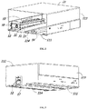
FIG. 2 is an assembly view of a liner and the slide rail cabling mechanism in the refrigerator according to the present invention; -
FIG. 3 is a structural schematic view of the liner and the slide rail cabling mechanism ofFIG. 2 from another perspective; -
FIG. 4 is an assembly view of the slide rail cabling mechanism of the refrigerator according to the present invention; -
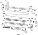
FIG. 5 is an exploded view of the slide rail cabling mechanism of the refrigerator according to the present invention; -
FIG. 6 is a structural schematic view of a first cabling box of the slide rail cabling mechanism of the refrigerator according to the present invention; -
FIG. 7 is a structural schematic view of a second cabling box of the slide rail cabling mechanism of the refrigerator according to the present invention. - The present invention will be described in detail in conjunction with embodiments shown in the figures. However, these embodiments are not intended to limit the present invention. Structural, methodological or functional variations made by those having ordinary skill in the art according to these embodiments are all included in the extent of protection of the present invention.
- Referring to
FIG. 1 , arefrigerator 100 according to the present invention comprises acompartment 10 opened forward and a drawer-type door 20 which is movable back and forth to open or close thecompartment 10. The drawer-type door 20 is provided with an electrical component which may be atouch display screen 30; adrawer box 40 for storing items is provided at a rear side of the drawer-type door 20. - With reference to
FIG. 2 and FIG. 3 , in thecompartment 10 is disposed aliner 11 opened ahead and configured to receive thedrawer box 40, and theliner 11 has abottom wall 111, arear wall 112 and twosidewalls 113. Here, thebottom wall 111, therear wall 112 and the two sidewalls of theliner 11 may be understood as the bottom wall, rear wall and sidewalls of thecompartment 10. - Referring to
FIG. 4 through FIG. 7 , the refrigerator further comprises a sliderail cabling mechanism 50 which includes asupport frame 51 and aslide assembly 52 fixed to the rear side of thedoor 20. Thesupport frame 51 is mounted on thesidewall 113 movably in a front-rear direction, and thesupport frame 51 is used to support thedrawer box 40. Specifically, theslide assembly 52 comprisesfixed frames 521 oppositely disposed on the twosidewalls 113 andslide rails 522 mounted on thefixed frames 521, and theslide rails 522 are used to achieve sliding engagement of thesupport frame 51 and thefixed frame 521; theslide rail 522 is preferably a three-stage slide rail. - The slide
rail cabling mechanism 50 further comprises acable 53 for powering thetouch display screen 30, afirst cabling box 54 fixed on the inner side of the compartment and asecond cabling box 55 fixed on thesupport frame 51. Thefirst cabling box 54 is formed with a first receivingportion 541 and a second receivingportion 542 below thedrawer box 40; thesecond cabling box 55 is formed with a fixedreceiving section 551 extending in the front-rear direction and aguide section 552 located in the rear of the fixedreceiving section 551. A distance between thesecond cabling box 55 and the second receivingportion 542 is set to 15-20 times a diameter of thecable 53 so that thecable 53 maintains a suitable curvature. - The
cable 53 has afixed section 531 fixed in thefirst receiving portion 541 and amovable section 532 extending from thefixed section 531 towards thesecond cabling box 55, and the second receivingportion 542 is used to receive part of themovable section 532; thecable 53 further comprises anotherfixed section 533 received in the fixedreceiving section 551, and both ends of thecable 53 are respectively provided with afirst terminal 534 and asecond terminal 535. Correspondingly, the drawer-type door 20 is provided with afirst connector 21 connected with the first terminal, and asecond connector 12 connected with thesecond terminal 535 is disposed in thecompartment 10. In addition, a sheath (not shown) is circumferentially provided around at least a portion of thecable 53 to reinforce the structural strength of thecable 53. The sheath may be made of a material such as a wire mesh or resin, and the sheath is preferably disposed on the outer circumference of themovable section 532 of thecable 53. - In addition, both the first receiving
portion 541 and second receivingportion 542 are disposed spaced apart from thebottom wall 113 to avoid the erosion that might be caused by the condensate water staying on thebottom wall 113 to thecable 53, and prevent occurrence of abnormities such as electric leakage. In the present embodiment, a partial area of thebottom wall 113 is recessed downward to form agroove 114, and the first receivingportion 541 and the second receivingportion 542 are correspondingly disposed above thegroove 114 and spaced apart from the bottom of thegroove 114. The setting of thegroove 114 reduces occupation of the space between thebottom wall 111 and thedrawer box 40 by thefirst cabling box 54, and then may appropriately reduce thebottom wall 111 and thedrawer box 40. Furthermore, thesecond receiving portion 542 is preferably not lower than the position of the opening of thegroove 114 in height to avoid wear of thecable 53. - A front end and a rear end of the
first cabling box 54 are respectively formed with a first fixedportion 543 and a second fixedportion 544, and the first receivingportion 541 and thesecond receiving portion 542 are both located between the first fixedportion 543 and the second fixedportion 544 in a front-rear direction. The sliderail cabling mechanism 50 further comprises a base 56 fixed on thebottom wall 111 and arear connection box 57 fixed on therear wall 112, and the first fixedportion 543 is fixed with thebase 56; the second fixedportion 544 is fixed with therear connection box 57. - Specifically, the
base 56 may be preset at a given position of thebottom wall 111, and then fixed by foaming, or formed on theliner 11 and then fixedly mounted on thebottom wall 111. Thebase 56 is preferably disposed and mounted in thegroove 114, and thebase 56 is disposed with a gap with the periphery of thegroove 114. The first fixedportion 543 is pressed down on thebase 56, and opened downward so that thebase 56 is completely received on the inner side of the first fixedportion 543. The first fixedportion 543 is formed with a plurality of fixingribs 5431 which are opposed to one another in a left-right direction and pressed against the surface of thebase 56. The fixingribs 5431 arranged opposed to one another in the left-right direction gradually narrow towards the center in an up-down direction to facilitate the installation of the first fixedportion 543. - In order to achieve stable installation of the first fixed
portion 543, thebase 56 is also formed with a mountinghole 561 that is disposed backward and obliquely downward. A mountingsurface 562 of the base 56 where the mountinghole 561 is provided is disposed forward and obliquely upward. The first fixedportion 543 of thefirst cabling box 54 is formed with a fixingsurface 5432 abutting against the mountingsurface 562, and the fixingsurface 5432 is provided with afixing hole 5433 at a position corresponding to the mountinghole 561, and the affixation and mounting of the two may be achieved by a screw (not shown). Here, the mountinghole 561 and thefixing hole 5433 are arranged obliquely, which facilitates on-site assembly, and when the space in thecompartment 10 is small, the mounting operation is not affected. - The
rear connection box 57 may also be pre-fixed on therear wall 112. Therear connection box 57 has adocking portion 571 protruding forward. Thedocking portion 571 is configured as a rectangular frame shape opened downward to prevent the water vapor on the upper side and both sides from entering the interior of therear connection box 57. Thesecond fixing portion 544 is snap-fitted on thedocking portion 571 to realize the fixing of the rear end of thefirst cabling box 54. In other embodiments of the present invention, therear connection box 57 may also be directly fixed on thebottom wall 111, so that thesecond connector 12 is exposed toward the interior of thecompartment 10 to connect with thecable 53. - A plurality of first fixing members5411 for fixing the fixed
section 531 are provided in the first receivingportion 541. Specifically, the first fixing members5411 are preferably set as plate-shaped or hook-shaped protrusions integrally formed with the first receivingportion 541, and the protrusions are arranged at different positions to limit the movement of the fixedsection 531 in a vertical direction and a horizontal direction. Here, the first receivingportion 541 comprises alinear receiving space 5412 extending back and forth, and anarcuate receiving space 5413 located in front of thelinear receiving space 5412 and communicated with thesecond receiving portion 542. Thearcuate receiving space 5413 is preferably set in a semicircular shape, that is, thecable 53 is bent 180° from front to back and then enters thesecond receiving portion 542. Thesecond receiving portion 542 is provided with a limitingmember 5421 at an end adjacent to thearcuate receiving space 5413 to avoid the movement of thecable 53; a side of the rear end of thesecond receiving portion 542 facing thesecond cabling box 55 is also set as an arcuate surface to better limit the bending direction of thecable 53 when the drawer box is retracted into thecompartment 10. In addition, the first receivingportion 541 further comprises abent receiving space 5414 located in rear of thelinear receiving space 5412, so that the rear end of the fixedsection 531 is located exactly at an intermediate position of thefirst cabling box 54 in the left-right direction to facilitate assembling and connection of thecable 53 and thecompartment 10. - The
second cabling box 55 further has a mountingopening 553 located between thefixed receiving section 551 and theguide section 552. The fixedreceiving section 551 is provided with a plurality ofsecond fixing members 5511 for restricting the movement of thecable 53. Thesecond fixing members 5511 are preferably configured as plate-shaped or hook-shaped protrusions integrally formed inside the fixedreceiving section 551, and the protrusions are arranged at different positions to limit the movement of a corresponding portion of thecable 53 in a vertical direction and a horizontal direction. The fixedreceiving section 551 is located below thedrawer box 40 and not lower than thefirst cabling box 54 in the vertical direction. Preferably, the fixedreceiving section 551 is slightly higher than thesecond receiving portion 542, thereby avoiding frictional damage between themovable section 532 of thecable 53 and thebottom wall 111. - The
guide section 552 and the fixedreceiving section 551 are integrally formed, and needn't be mounted and fixed together again on the spot. Theguide section 552 is formed with aguide surface 554 extending backward and toward the inner side of thecompartment 10 in the left-right direction. Theguide surface 554 is preferably an arcuate surface. At least one of thefirst terminal 534 and thesecond terminal 535 may pass through the mountingopening 553 to facilitate the mounting of thecable 53. Thesecond cabling box 55 is further formed with at least two snap-fittingportions 555 which are spaced apart in the front-rear direction and snap-fitted with thesupport frame 51 to achieve the fixing and mounting of thesecond cabling box 55. - In addition, the sliding
rail cabling mechanism 50 comprises adoor support iron 58 fixed on the rear side of the drawer-type door 20 and fixed with thesupport frame 51, a connectingwindow 581 is provided on thedoor support iron 58, and the sliderail cabling mechanism 50 further comprises a front connection box 59 detachably mounted on the connectingwindow 581. - In summary, in the
refrigerator 100 of the present invention, the first receivingportion 541 and thesecond receiving portion 542 of thefirst cabling box 54 are arranged below thedrawer box 40, a portion of themovable section 532 of thecable 53 is received in thesecond receiving portion 542, the other portion of themovable section 532 is freely movable between thedrawer box 40 and thebottom wall 111, theguide surface 554 formed by theguide section 552 at the rear end of thesecond cabling box 55 also helps themovable end 532 to maintain a suitable state, avoiding thecable 53 from moving to between thedrawer box 40 and thesidewall 113 and from being pressed to deform. Thefirst cabling box 54 is disposed away from thesupport frame 51, thereby reducing the bending stress of thecable 53, better avoiding thecable 53 from excessive deformation and distortion and damages, and effectively ensuring normal operation of the electrical component on the drawer-type door 20. - It should be understood that although the description is described according to the embodiments, not every embodiment only includes one independent technical solution, that such a description manner is only for the sake of clarity, that those skilled in the art should take the description as an integral part, and that the technical solutions in the embodiments may be suitably combined to form other embodiments understandable by those skilled in the art.
- The detailed descriptions set forth above are merely specific illustrations of feasible embodiments of the present invention, and are not intended to limit the scope of protection of the present invention. All equivalent embodiments or modifications that do not depart from the art spirit of the present invention should fall within the scope of protection of the present invention.
Claims (18)
- A refrigerator having a slide rail cabling mechanism, comprising a compartment opened forward and a drawer-type door which is movable back and forth to open or close the compartment, the compartment having a bottom wall, a rear wall and two sidewalls, the drawer-type door being provided with an electrical component, a support frame movably mounted on the sidewall in a front-rear direction being further disposed on a rear side of the drawer-type door, the support frame being used to support a drawer box, wherein the slide rail cabling mechanism comprises a cable for powering the electrical component, a first cabling box fixed on an inner side of the compartment and a second cabling box fixed on the support frame; the first cabling box is formed with a first receiving portion and a second receiving portion below the drawer box, the cable having a fixed section fixed in the first receiving portion and a movable section extending from the fixed section towards the second cabling box, the second receiving portion being used to receive part of the movable section; the second cabling box is formed with a fixed receiving section extending in the front-rear direction.
- The refrigerator according to claim 1, wherein both the first receiving portion and second receiving portion are disposed spaced apart from the bottom wall.
- The refrigerator according to claim 2, wherein a partial area of the bottom wall is recessed downward to form a groove, and the first receiving portion and the second receiving portion are correspondingly disposed above the groove.
- The refrigerator according to claim 1, wherein a front end and a rear end of the first cabling box are respectively formed with a first fixed portion and a second fixed portion, and the first receiving portion and the second receiving portion are both located between the first fixed portion and the second fixed portion in the front-rear direction.
- The refrigerator according to claim 4, wherein the slide rail cabling mechanism further comprises a base fixed on the bottom wall, and the first fixed portion is fixed with the base.
- The refrigerator according to claim 5, wherein the first fixed portion is pressed down on the base, and the first fixed portion is formed with a plurality of fixing ribs which are opposed to one another in a left-right direction and pressed against the surface of the base.
- The refrigerator according to claim 5, wherein the base is formed with a mounting hole that is disposed backward and obliquely downward, and the first cabling box is provided with a fixing hole at a position corresponding to the mounting hole.
- The refrigerator according to claim 4, wherein the slide rail cabling mechanism further comprises a rear connection box fixed on the rear wall, and the second fixed portion is fixed with the rear connection box.
- The refrigerator according to claim 1, wherein a plurality of first fixing members for fixing the fixed section are provided in the first receiving portion.
- The refrigerator according to claim 1, wherein the first receiving portion comprises a linear receiving space extending back and forth, and an arcuate receiving space located in front of the linear receiving space and communicated with the second receiving portion, and the second receiving portion is provided with a limiting member at an end adjacent to the arcuate receiving space.
- The refrigerator according to claim 1, wherein the second cabling box is further formed with a guide section located in the rear of the fixed receiving section, and the guide section is formed with a guide surface extending backward and toward the inner side of the compartment in the left-right direction.
- The refrigerator according to claim 11, wherein the second cabling box further has a mounting opening located between the fixed receiving section and the guide section, both ends of the cable are respectively provided with a first terminal and a second terminal, and at least one of both the first terminal and the second terminal may pass through the mounting opening.
- The refrigerator according to claim 1, wherein the second cabling box is further formed with at least two snap-fitting portions which are spaced apart in the front-rear direction and snap-fitted with the support frame.
- The refrigerator according to claim 1, wherein the fixed receiving section is provided with a plurality of second fixing members for restricting the movement of the cable.
- The refrigerator according to claim 1, wherein the sliding rail cabling mechanism comprises a door support iron fixed on the rear side of the drawer-type door and fixed with the support frame, a connecting window is provided on the door support iron, and the slide rail cabling mechanism further comprises a front connection box detachably mounted on the connecting window.
- The refrigerator according to claim 1, wherein a distance between the second cabling box and the second receiving portion is set to 15-20 times a diameter of the cable.
- The refrigerator according to claim 1, wherein the fixed receiving section is located below the drawer box and not lower than the first cabling box in the vertical direction.
- The refrigerator according to claim 1, wherein a sheath is circumferentially provided around at least a portion of the cable.
Applications Claiming Priority (2)
| Application Number | Priority Date | Filing Date | Title |
|---|---|---|---|
| CN201811612927.5A CN109780806B (en) | 2018-12-27 | 2018-12-27 | Refrigerator with sliding rail routing mechanism |
| PCT/CN2019/105073 WO2020134184A1 (en) | 2018-12-27 | 2019-09-10 | Refrigerator having slide rail cabling mechanism |
Publications (3)
| Publication Number | Publication Date |
|---|---|
| EP3904800A1 true EP3904800A1 (en) | 2021-11-03 |
| EP3904800A4 EP3904800A4 (en) | 2022-03-09 |
| EP3904800B1 EP3904800B1 (en) | 2022-12-14 |
Family
ID=66497724
Family Applications (1)
| Application Number | Title | Priority Date | Filing Date |
|---|---|---|---|
| EP19906135.9A Active EP3904800B1 (en) | 2018-12-27 | 2019-09-10 | Refrigerator having a slide rail cabling mechanism |
Country Status (4)
| Country | Link |
|---|---|
| US (1) | US11079170B2 (en) |
| EP (1) | EP3904800B1 (en) |
| CN (1) | CN109780806B (en) |
| WO (1) | WO2020134184A1 (en) |
Families Citing this family (12)
| Publication number | Priority date | Publication date | Assignee | Title |
|---|---|---|---|---|
| CN110579070B (en) * | 2018-08-08 | 2021-07-23 | 重庆海尔制冷电器有限公司 | Refrigerator with sliding rail routing mechanism |
| CN109780806B (en) * | 2018-12-27 | 2020-04-21 | 青岛海尔股份有限公司 | Refrigerator with sliding rail routing mechanism |
| CN112013619B (en) * | 2019-05-29 | 2021-10-29 | 青岛海尔电冰箱有限公司 | Refrigerator with sliding rail routing mechanism |
| KR102836705B1 (en) * | 2019-07-12 | 2025-07-18 | 엘지전자 주식회사 | refrigerator |
| CN112323372B (en) * | 2020-11-28 | 2024-09-17 | 珠海格力电器股份有限公司 | Pipeline mounting structure and clothes treatment equipment comprising same |
| CN112323370A (en) * | 2020-11-28 | 2021-02-05 | 珠海格力电器股份有限公司 | Pipeline mounting structure reaches clothing treatment facility including it |
| CN112323383B (en) * | 2020-11-28 | 2025-03-14 | 珠海格力电器股份有限公司 | A rotatable pipeline support structure and a clothes processing device including the same |
| CN112323365B (en) * | 2020-11-28 | 2025-09-23 | 珠海格力电器股份有限公司 | Pipeline installation structure and clothing processing equipment including the same |
| KR102538004B1 (en) | 2021-04-08 | 2023-05-30 | 엘지전자 주식회사 | Refrigerator |
| TR2021020762A2 (en) * | 2021-12-23 | 2023-07-21 | Bsh Ev Aletleri Sanayi Ve Ticaret Anonim Sirketi | A DRAWER ASSEMBLY FOR A HOME APPLIANCE |
| KR20230161749A (en) * | 2022-05-19 | 2023-11-28 | 엘지전자 주식회사 | Refrigerator |
| CN116785461B (en) * | 2023-03-29 | 2026-04-24 | 安庆师范大学 | A disinfection box for monitoring migratory bird diseases |
Family Cites Families (14)
| Publication number | Priority date | Publication date | Assignee | Title |
|---|---|---|---|---|
| KR100565695B1 (en) * | 2004-10-26 | 2006-03-29 | 엘지전자 주식회사 | Refrigerator |
| US8291816B2 (en) * | 2008-06-04 | 2012-10-23 | Sharp Kabushiki Kaisha | Drawer type cooking device |
| KR101831614B1 (en) * | 2010-01-28 | 2018-02-26 | 삼성전자주식회사 | Refrigerator |
| KR101949435B1 (en) * | 2010-01-28 | 2019-02-18 | 삼성전자주식회사 | Refrigerator |
| US9585474B2 (en) * | 2013-07-17 | 2017-03-07 | Whirlpool Corporation | Traveling harness system |
| CN107949679B (en) * | 2015-07-20 | 2020-12-29 | 雅固拉国际有限公司 | Electronically Controlled Drawer Slide Locks for Cabinets and Hubs for Drawer Slide Locks |
| CN105300021B (en) | 2015-12-03 | 2018-04-20 | 青岛海尔股份有限公司 | Slide gear alignment apartment |
| CN106871529A (en) * | 2017-02-09 | 2017-06-20 | 青岛海尔股份有限公司 | Refrigerator |
| CN108426415B (en) * | 2018-06-21 | 2019-07-30 | 合肥华凌股份有限公司 | Refrigerator drawer assembly and refrigerator |
| CN109028727B (en) * | 2018-06-21 | 2019-07-30 | 合肥华凌股份有限公司 | Wire harness retracting device for drawer type refrigerator and refrigerator having the same |
| CN109028726B (en) * | 2018-06-21 | 2020-04-21 | 合肥华凌股份有限公司 | Be applied to lead wire structure, pull, box and refrigerator of pull |
| CN109780806B (en) | 2018-12-27 | 2020-04-21 | 青岛海尔股份有限公司 | Refrigerator with sliding rail routing mechanism |
| CN109780805B (en) | 2018-12-27 | 2020-08-28 | 海尔智家股份有限公司 | Refrigerator with sliding rail routing mechanism |
| JP7230605B2 (en) * | 2019-03-18 | 2023-03-01 | 富士フイルムビジネスイノベーション株式会社 | Harness connection structure and electronic equipment |
-
2018
- 2018-12-27 CN CN201811612927.5A patent/CN109780806B/en active Active
-
2019
- 2019-09-10 WO PCT/CN2019/105073 patent/WO2020134184A1/en not_active Ceased
- 2019-09-10 EP EP19906135.9A patent/EP3904800B1/en active Active
- 2019-09-10 US US17/042,163 patent/US11079170B2/en active Active
Also Published As
| Publication number | Publication date |
|---|---|
| US20210018260A1 (en) | 2021-01-21 |
| US11079170B2 (en) | 2021-08-03 |
| EP3904800A4 (en) | 2022-03-09 |
| WO2020134184A1 (en) | 2020-07-02 |
| EP3904800B1 (en) | 2022-12-14 |
| CN109780806B (en) | 2020-04-21 |
| CN109780806A (en) | 2019-05-21 |
Similar Documents
| Publication | Publication Date | Title |
|---|---|---|
| EP3904800B1 (en) | Refrigerator having a slide rail cabling mechanism | |
| CN109780805B (en) | Refrigerator with sliding rail routing mechanism | |
| EP2354735B1 (en) | Refrigerator | |
| US11624554B2 (en) | Household appliance | |
| CN102954656A (en) | Household appliance | |
| EP3926267B1 (en) | Refrigerator having wiring mechanism | |
| EP3978845B1 (en) | Refrigerator having slide rail cabling mechanism | |
| EP3553433B1 (en) | Refrigeration appliance | |
| CN111550972B (en) | Walk line mechanism and have this refrigerator of walking line mechanism | |
| CN112033063B (en) | Refrigerator with a door | |
| CN113819697B (en) | Freezer | |
| CN117006796A (en) | Refrigerator drawers and refrigerators | |
| CN207065977U (en) | refrigerator | |
| CN111550967A (en) | Cable routing mechanism and refrigerator with the same | |
| CN110081657B (en) | Household appliance with a functional module including a line receiver and method for assembling the household appliance | |
| CN111550970B (en) | Walk line mechanism and have this refrigerator of walking line mechanism | |
| CN111550968B (en) | Wire routing mechanism and refrigerator with the wire routing mechanism | |
| CN111550966B (en) | Walk line mechanism and have this refrigerator of walking line mechanism | |
| CN111550973A (en) | Cable routing mechanism and refrigerator with the same | |
| JP2020076507A (en) | refrigerator | |
| CN111550971A (en) | Walk line mechanism and have this refrigerator of walking line mechanism | |
| CN111550969A (en) | Cable routing mechanism and refrigerator with the same |
Legal Events
| Date | Code | Title | Description |
|---|---|---|---|
| STAA | Information on the status of an ep patent application or granted ep patent |
Free format text: STATUS: THE INTERNATIONAL PUBLICATION HAS BEEN MADE |
|
| PUAI | Public reference made under article 153(3) epc to a published international application that has entered the european phase |
Free format text: ORIGINAL CODE: 0009012 |
|
| STAA | Information on the status of an ep patent application or granted ep patent |
Free format text: STATUS: REQUEST FOR EXAMINATION WAS MADE |
|
| 17P | Request for examination filed |
Effective date: 20200930 |
|
| AK | Designated contracting states |
Kind code of ref document: A1 Designated state(s): AL AT BE BG CH CY CZ DE DK EE ES FI FR GB GR HR HU IE IS IT LI LT LU LV MC MK MT NL NO PL PT RO RS SE SI SK SM TR |
|
| A4 | Supplementary search report drawn up and despatched |
Effective date: 20220203 |
|
| RIC1 | Information provided on ipc code assigned before grant |
Ipc: F25D 25/02 20060101AFI20220128BHEP |
|
| DAV | Request for validation of the european patent (deleted) | ||
| DAX | Request for extension of the european patent (deleted) | ||
| GRAP | Despatch of communication of intention to grant a patent |
Free format text: ORIGINAL CODE: EPIDOSNIGR1 |
|
| STAA | Information on the status of an ep patent application or granted ep patent |
Free format text: STATUS: GRANT OF PATENT IS INTENDED |
|
| INTG | Intention to grant announced |
Effective date: 20220726 |
|
| GRAS | Grant fee paid |
Free format text: ORIGINAL CODE: EPIDOSNIGR3 |
|
| GRAA | (expected) grant |
Free format text: ORIGINAL CODE: 0009210 |
|
| STAA | Information on the status of an ep patent application or granted ep patent |
Free format text: STATUS: THE PATENT HAS BEEN GRANTED |
|
| AK | Designated contracting states |
Kind code of ref document: B1 Designated state(s): AL AT BE BG CH CY CZ DE DK EE ES FI FR GB GR HR HU IE IS IT LI LT LU LV MC MK MT NL NO PL PT RO RS SE SI SK SM TR |
|
| REG | Reference to a national code |
Ref country code: GB Ref legal event code: FG4D |
|
| REG | Reference to a national code |
Ref country code: CH Ref legal event code: EP |
|
| REG | Reference to a national code |
Ref country code: DE Ref legal event code: R096 Ref document number: 602019023275 Country of ref document: DE |
|
| REG | Reference to a national code |
Ref country code: IE Ref legal event code: FG4D |
|
| REG | Reference to a national code |
Ref country code: AT Ref legal event code: REF Ref document number: 1537915 Country of ref document: AT Kind code of ref document: T Effective date: 20230115 |
|
| REG | Reference to a national code |
Ref country code: RO Ref legal event code: EPE |
|
| REG | Reference to a national code |
Ref country code: LT Ref legal event code: MG9D |
|
| REG | Reference to a national code |
Ref country code: NL Ref legal event code: MP Effective date: 20221214 |
|
| PG25 | Lapsed in a contracting state [announced via postgrant information from national office to epo] |
Ref country code: SE Free format text: LAPSE BECAUSE OF FAILURE TO SUBMIT A TRANSLATION OF THE DESCRIPTION OR TO PAY THE FEE WITHIN THE PRESCRIBED TIME-LIMIT Effective date: 20221214 Ref country code: NO Free format text: LAPSE BECAUSE OF FAILURE TO SUBMIT A TRANSLATION OF THE DESCRIPTION OR TO PAY THE FEE WITHIN THE PRESCRIBED TIME-LIMIT Effective date: 20230314 Ref country code: LT Free format text: LAPSE BECAUSE OF FAILURE TO SUBMIT A TRANSLATION OF THE DESCRIPTION OR TO PAY THE FEE WITHIN THE PRESCRIBED TIME-LIMIT Effective date: 20221214 Ref country code: FI Free format text: LAPSE BECAUSE OF FAILURE TO SUBMIT A TRANSLATION OF THE DESCRIPTION OR TO PAY THE FEE WITHIN THE PRESCRIBED TIME-LIMIT Effective date: 20221214 |
|
| REG | Reference to a national code |
Ref country code: AT Ref legal event code: MK05 Ref document number: 1537915 Country of ref document: AT Kind code of ref document: T Effective date: 20221214 |
|
| PG25 | Lapsed in a contracting state [announced via postgrant information from national office to epo] |
Ref country code: RS Free format text: LAPSE BECAUSE OF FAILURE TO SUBMIT A TRANSLATION OF THE DESCRIPTION OR TO PAY THE FEE WITHIN THE PRESCRIBED TIME-LIMIT Effective date: 20221214 Ref country code: LV Free format text: LAPSE BECAUSE OF FAILURE TO SUBMIT A TRANSLATION OF THE DESCRIPTION OR TO PAY THE FEE WITHIN THE PRESCRIBED TIME-LIMIT Effective date: 20221214 Ref country code: HR Free format text: LAPSE BECAUSE OF FAILURE TO SUBMIT A TRANSLATION OF THE DESCRIPTION OR TO PAY THE FEE WITHIN THE PRESCRIBED TIME-LIMIT Effective date: 20221214 Ref country code: GR Free format text: LAPSE BECAUSE OF FAILURE TO SUBMIT A TRANSLATION OF THE DESCRIPTION OR TO PAY THE FEE WITHIN THE PRESCRIBED TIME-LIMIT Effective date: 20230315 |
|
| PG25 | Lapsed in a contracting state [announced via postgrant information from national office to epo] |
Ref country code: NL Free format text: LAPSE BECAUSE OF FAILURE TO SUBMIT A TRANSLATION OF THE DESCRIPTION OR TO PAY THE FEE WITHIN THE PRESCRIBED TIME-LIMIT Effective date: 20221214 |
|
| PG25 | Lapsed in a contracting state [announced via postgrant information from national office to epo] |
Ref country code: SM Free format text: LAPSE BECAUSE OF FAILURE TO SUBMIT A TRANSLATION OF THE DESCRIPTION OR TO PAY THE FEE WITHIN THE PRESCRIBED TIME-LIMIT Effective date: 20221214 Ref country code: PT Free format text: LAPSE BECAUSE OF FAILURE TO SUBMIT A TRANSLATION OF THE DESCRIPTION OR TO PAY THE FEE WITHIN THE PRESCRIBED TIME-LIMIT Effective date: 20230414 Ref country code: ES Free format text: LAPSE BECAUSE OF FAILURE TO SUBMIT A TRANSLATION OF THE DESCRIPTION OR TO PAY THE FEE WITHIN THE PRESCRIBED TIME-LIMIT Effective date: 20221214 Ref country code: EE Free format text: LAPSE BECAUSE OF FAILURE TO SUBMIT A TRANSLATION OF THE DESCRIPTION OR TO PAY THE FEE WITHIN THE PRESCRIBED TIME-LIMIT Effective date: 20221214 Ref country code: CZ Free format text: LAPSE BECAUSE OF FAILURE TO SUBMIT A TRANSLATION OF THE DESCRIPTION OR TO PAY THE FEE WITHIN THE PRESCRIBED TIME-LIMIT Effective date: 20221214 Ref country code: AT Free format text: LAPSE BECAUSE OF FAILURE TO SUBMIT A TRANSLATION OF THE DESCRIPTION OR TO PAY THE FEE WITHIN THE PRESCRIBED TIME-LIMIT Effective date: 20221214 |
|
| PG25 | Lapsed in a contracting state [announced via postgrant information from national office to epo] |
Ref country code: SK Free format text: LAPSE BECAUSE OF FAILURE TO SUBMIT A TRANSLATION OF THE DESCRIPTION OR TO PAY THE FEE WITHIN THE PRESCRIBED TIME-LIMIT Effective date: 20221214 Ref country code: PL Free format text: LAPSE BECAUSE OF FAILURE TO SUBMIT A TRANSLATION OF THE DESCRIPTION OR TO PAY THE FEE WITHIN THE PRESCRIBED TIME-LIMIT Effective date: 20221214 Ref country code: IS Free format text: LAPSE BECAUSE OF FAILURE TO SUBMIT A TRANSLATION OF THE DESCRIPTION OR TO PAY THE FEE WITHIN THE PRESCRIBED TIME-LIMIT Effective date: 20230414 Ref country code: AL Free format text: LAPSE BECAUSE OF FAILURE TO SUBMIT A TRANSLATION OF THE DESCRIPTION OR TO PAY THE FEE WITHIN THE PRESCRIBED TIME-LIMIT Effective date: 20221214 |
|
| REG | Reference to a national code |
Ref country code: DE Ref legal event code: R097 Ref document number: 602019023275 Country of ref document: DE |
|
| PLBE | No opposition filed within time limit |
Free format text: ORIGINAL CODE: 0009261 |
|
| STAA | Information on the status of an ep patent application or granted ep patent |
Free format text: STATUS: NO OPPOSITION FILED WITHIN TIME LIMIT |
|
| PG25 | Lapsed in a contracting state [announced via postgrant information from national office to epo] |
Ref country code: DK Free format text: LAPSE BECAUSE OF FAILURE TO SUBMIT A TRANSLATION OF THE DESCRIPTION OR TO PAY THE FEE WITHIN THE PRESCRIBED TIME-LIMIT Effective date: 20221214 |
|
| 26N | No opposition filed |
Effective date: 20230915 |
|
| PG25 | Lapsed in a contracting state [announced via postgrant information from national office to epo] |
Ref country code: SI Free format text: LAPSE BECAUSE OF FAILURE TO SUBMIT A TRANSLATION OF THE DESCRIPTION OR TO PAY THE FEE WITHIN THE PRESCRIBED TIME-LIMIT Effective date: 20221214 |
|
| REG | Reference to a national code |
Ref country code: CH Ref legal event code: PL |
|
| PG25 | Lapsed in a contracting state [announced via postgrant information from national office to epo] |
Ref country code: LU Free format text: LAPSE BECAUSE OF NON-PAYMENT OF DUE FEES Effective date: 20230910 |
|
| REG | Reference to a national code |
Ref country code: BE Ref legal event code: MM Effective date: 20230930 |
|
| PG25 | Lapsed in a contracting state [announced via postgrant information from national office to epo] |
Ref country code: LU Free format text: LAPSE BECAUSE OF NON-PAYMENT OF DUE FEES Effective date: 20230910 Ref country code: MC Free format text: LAPSE BECAUSE OF FAILURE TO SUBMIT A TRANSLATION OF THE DESCRIPTION OR TO PAY THE FEE WITHIN THE PRESCRIBED TIME-LIMIT Effective date: 20221214 |
|
| REG | Reference to a national code |
Ref country code: IE Ref legal event code: MM4A |
|
| PG25 | Lapsed in a contracting state [announced via postgrant information from national office to epo] |
Ref country code: IE Free format text: LAPSE BECAUSE OF NON-PAYMENT OF DUE FEES Effective date: 20230910 |
|
| PG25 | Lapsed in a contracting state [announced via postgrant information from national office to epo] |
Ref country code: CH Free format text: LAPSE BECAUSE OF NON-PAYMENT OF DUE FEES Effective date: 20230930 |
|
| PG25 | Lapsed in a contracting state [announced via postgrant information from national office to epo] |
Ref country code: IE Free format text: LAPSE BECAUSE OF NON-PAYMENT OF DUE FEES Effective date: 20230910 Ref country code: CH Free format text: LAPSE BECAUSE OF NON-PAYMENT OF DUE FEES Effective date: 20230930 |
|
| PG25 | Lapsed in a contracting state [announced via postgrant information from national office to epo] |
Ref country code: BE Free format text: LAPSE BECAUSE OF NON-PAYMENT OF DUE FEES Effective date: 20230930 |
|
| PG25 | Lapsed in a contracting state [announced via postgrant information from national office to epo] |
Ref country code: BG Free format text: LAPSE BECAUSE OF FAILURE TO SUBMIT A TRANSLATION OF THE DESCRIPTION OR TO PAY THE FEE WITHIN THE PRESCRIBED TIME-LIMIT Effective date: 20221214 |
|
| PG25 | Lapsed in a contracting state [announced via postgrant information from national office to epo] |
Ref country code: BG Free format text: LAPSE BECAUSE OF FAILURE TO SUBMIT A TRANSLATION OF THE DESCRIPTION OR TO PAY THE FEE WITHIN THE PRESCRIBED TIME-LIMIT Effective date: 20221214 |
|
| PG25 | Lapsed in a contracting state [announced via postgrant information from national office to epo] |
Ref country code: CY Free format text: LAPSE BECAUSE OF FAILURE TO SUBMIT A TRANSLATION OF THE DESCRIPTION OR TO PAY THE FEE WITHIN THE PRESCRIBED TIME-LIMIT; INVALID AB INITIO Effective date: 20190910 |
|
| PG25 | Lapsed in a contracting state [announced via postgrant information from national office to epo] |
Ref country code: HU Free format text: LAPSE BECAUSE OF FAILURE TO SUBMIT A TRANSLATION OF THE DESCRIPTION OR TO PAY THE FEE WITHIN THE PRESCRIBED TIME-LIMIT; INVALID AB INITIO Effective date: 20190910 |
|
| PGFP | Annual fee paid to national office [announced via postgrant information from national office to epo] |
Ref country code: DE Payment date: 20250916 Year of fee payment: 7 |
|
| PGFP | Annual fee paid to national office [announced via postgrant information from national office to epo] |
Ref country code: IT Payment date: 20250909 Year of fee payment: 7 |
|
| PGFP | Annual fee paid to national office [announced via postgrant information from national office to epo] |
Ref country code: GB Payment date: 20250919 Year of fee payment: 7 |
|
| PGFP | Annual fee paid to national office [announced via postgrant information from national office to epo] |
Ref country code: FR Payment date: 20250929 Year of fee payment: 7 |
|
| PGFP | Annual fee paid to national office [announced via postgrant information from national office to epo] |
Ref country code: RO Payment date: 20250901 Year of fee payment: 7 |
|
| PG25 | Lapsed in a contracting state [announced via postgrant information from national office to epo] |
Ref country code: TR Free format text: LAPSE BECAUSE OF FAILURE TO SUBMIT A TRANSLATION OF THE DESCRIPTION OR TO PAY THE FEE WITHIN THE PRESCRIBED TIME-LIMIT Effective date: 20221214 |