EP3904774A1 - Air purifier comprising flow path control member - Google Patents
Air purifier comprising flow path control member Download PDFInfo
- Publication number
- EP3904774A1 EP3904774A1 EP19904105.4A EP19904105A EP3904774A1 EP 3904774 A1 EP3904774 A1 EP 3904774A1 EP 19904105 A EP19904105 A EP 19904105A EP 3904774 A1 EP3904774 A1 EP 3904774A1
- Authority
- EP
- European Patent Office
- Prior art keywords
- flow path
- discharge
- air
- control member
- discharge port
- Prior art date
- Legal status (The legal status is an assumption and is not a legal conclusion. Google has not performed a legal analysis and makes no representation as to the accuracy of the status listed.)
- Granted
Links
Images




Classifications
-
- F—MECHANICAL ENGINEERING; LIGHTING; HEATING; WEAPONS; BLASTING
- F24—HEATING; RANGES; VENTILATING
- F24F—AIR-CONDITIONING; AIR-HUMIDIFICATION; VENTILATION; USE OF AIR CURRENTS FOR SCREENING
- F24F8/00—Treatment, e.g. purification, of air supplied to human living or working spaces otherwise than by heating, cooling, humidifying or drying
- F24F8/80—Self-contained air purifiers
-
- F—MECHANICAL ENGINEERING; LIGHTING; HEATING; WEAPONS; BLASTING
- F24—HEATING; RANGES; VENTILATING
- F24F—AIR-CONDITIONING; AIR-HUMIDIFICATION; VENTILATION; USE OF AIR CURRENTS FOR SCREENING
- F24F11/00—Control or safety arrangements
- F24F11/0008—Control or safety arrangements for air-humidification
-
- F—MECHANICAL ENGINEERING; LIGHTING; HEATING; WEAPONS; BLASTING
- F24—HEATING; RANGES; VENTILATING
- F24F—AIR-CONDITIONING; AIR-HUMIDIFICATION; VENTILATION; USE OF AIR CURRENTS FOR SCREENING
- F24F11/00—Control or safety arrangements
- F24F11/70—Control systems characterised by their outputs; Constructional details thereof
-
- F—MECHANICAL ENGINEERING; LIGHTING; HEATING; WEAPONS; BLASTING
- F24—HEATING; RANGES; VENTILATING
- F24F—AIR-CONDITIONING; AIR-HUMIDIFICATION; VENTILATION; USE OF AIR CURRENTS FOR SCREENING
- F24F11/00—Control or safety arrangements
- F24F11/70—Control systems characterised by their outputs; Constructional details thereof
- F24F11/72—Control systems characterised by their outputs; Constructional details thereof for controlling the supply of treated air, e.g. its pressure
- F24F11/79—Control systems characterised by their outputs; Constructional details thereof for controlling the supply of treated air, e.g. its pressure for controlling the direction of the supplied air
-
- F—MECHANICAL ENGINEERING; LIGHTING; HEATING; WEAPONS; BLASTING
- F24—HEATING; RANGES; VENTILATING
- F24F—AIR-CONDITIONING; AIR-HUMIDIFICATION; VENTILATION; USE OF AIR CURRENTS FOR SCREENING
- F24F13/00—Details common to, or for air-conditioning, air-humidification, ventilation or use of air currents for screening
- F24F13/08—Air-flow control members, e.g. louvres, grilles, flaps or guide plates
- F24F13/10—Air-flow control members, e.g. louvres, grilles, flaps or guide plates movable, e.g. dampers
- F24F13/14—Air-flow control members, e.g. louvres, grilles, flaps or guide plates movable, e.g. dampers built up of tilting members, e.g. louvre
-
- F—MECHANICAL ENGINEERING; LIGHTING; HEATING; WEAPONS; BLASTING
- F24—HEATING; RANGES; VENTILATING
- F24F—AIR-CONDITIONING; AIR-HUMIDIFICATION; VENTILATION; USE OF AIR CURRENTS FOR SCREENING
- F24F13/00—Details common to, or for air-conditioning, air-humidification, ventilation or use of air currents for screening
- F24F13/08—Air-flow control members, e.g. louvres, grilles, flaps or guide plates
- F24F13/10—Air-flow control members, e.g. louvres, grilles, flaps or guide plates movable, e.g. dampers
- F24F13/14—Air-flow control members, e.g. louvres, grilles, flaps or guide plates movable, e.g. dampers built up of tilting members, e.g. louvre
- F24F13/1413—Air-flow control members, e.g. louvres, grilles, flaps or guide plates movable, e.g. dampers built up of tilting members, e.g. louvre using more than one tilting member, e.g. with several pivoting blades
-
- F—MECHANICAL ENGINEERING; LIGHTING; HEATING; WEAPONS; BLASTING
- F24—HEATING; RANGES; VENTILATING
- F24F—AIR-CONDITIONING; AIR-HUMIDIFICATION; VENTILATION; USE OF AIR CURRENTS FOR SCREENING
- F24F13/00—Details common to, or for air-conditioning, air-humidification, ventilation or use of air currents for screening
- F24F13/20—Casings or covers
-
- F—MECHANICAL ENGINEERING; LIGHTING; HEATING; WEAPONS; BLASTING
- F24—HEATING; RANGES; VENTILATING
- F24F—AIR-CONDITIONING; AIR-HUMIDIFICATION; VENTILATION; USE OF AIR CURRENTS FOR SCREENING
- F24F13/00—Details common to, or for air-conditioning, air-humidification, ventilation or use of air currents for screening
- F24F13/28—Arrangement or mounting of filters
-
- F—MECHANICAL ENGINEERING; LIGHTING; HEATING; WEAPONS; BLASTING
- F24—HEATING; RANGES; VENTILATING
- F24F—AIR-CONDITIONING; AIR-HUMIDIFICATION; VENTILATION; USE OF AIR CURRENTS FOR SCREENING
- F24F6/00—Air-humidification, e.g. cooling by humidification
- F24F6/02—Air-humidification, e.g. cooling by humidification by evaporation of water in the air
- F24F6/04—Air-humidification, e.g. cooling by humidification by evaporation of water in the air using stationary unheated wet elements
- F24F6/043—Air-humidification, e.g. cooling by humidification by evaporation of water in the air using stationary unheated wet elements with self-sucking action, e.g. wicks
-
- F—MECHANICAL ENGINEERING; LIGHTING; HEATING; WEAPONS; BLASTING
- F24—HEATING; RANGES; VENTILATING
- F24F—AIR-CONDITIONING; AIR-HUMIDIFICATION; VENTILATION; USE OF AIR CURRENTS FOR SCREENING
- F24F8/00—Treatment, e.g. purification, of air supplied to human living or working spaces otherwise than by heating, cooling, humidifying or drying
- F24F8/10—Treatment, e.g. purification, of air supplied to human living or working spaces otherwise than by heating, cooling, humidifying or drying by separation, e.g. by filtering
- F24F8/108—Treatment, e.g. purification, of air supplied to human living or working spaces otherwise than by heating, cooling, humidifying or drying by separation, e.g. by filtering using dry filter elements
-
- F—MECHANICAL ENGINEERING; LIGHTING; HEATING; WEAPONS; BLASTING
- F24—HEATING; RANGES; VENTILATING
- F24F—AIR-CONDITIONING; AIR-HUMIDIFICATION; VENTILATION; USE OF AIR CURRENTS FOR SCREENING
- F24F8/00—Treatment, e.g. purification, of air supplied to human living or working spaces otherwise than by heating, cooling, humidifying or drying
- F24F8/10—Treatment, e.g. purification, of air supplied to human living or working spaces otherwise than by heating, cooling, humidifying or drying by separation, e.g. by filtering
- F24F8/117—Treatment, e.g. purification, of air supplied to human living or working spaces otherwise than by heating, cooling, humidifying or drying by separation, e.g. by filtering using wet filtering
-
- F—MECHANICAL ENGINEERING; LIGHTING; HEATING; WEAPONS; BLASTING
- F24—HEATING; RANGES; VENTILATING
- F24F—AIR-CONDITIONING; AIR-HUMIDIFICATION; VENTILATION; USE OF AIR CURRENTS FOR SCREENING
- F24F6/00—Air-humidification, e.g. cooling by humidification
- F24F2006/008—Air-humidifier with water reservoir
-
- F—MECHANICAL ENGINEERING; LIGHTING; HEATING; WEAPONS; BLASTING
- F24—HEATING; RANGES; VENTILATING
- F24F—AIR-CONDITIONING; AIR-HUMIDIFICATION; VENTILATION; USE OF AIR CURRENTS FOR SCREENING
- F24F13/00—Details common to, or for air-conditioning, air-humidification, ventilation or use of air currents for screening
- F24F13/20—Casings or covers
- F24F2013/205—Mounting a ventilator fan therein
Definitions
- the present invention relates to a humidification air purifier, and more particularly to a humidification air purifier including a flow path control member in which a plurality of discharge flow paths are controlled to select a plurality of discharge ports.
- an air purifier has been introduced which is capable of performing both a humidifying function and an air purification function in a single device.
- a plurality of discharge ports were not formed, various modes to meet the demand could not be implemented, and even if there were a plurality of discharge ports, there was a risk of malfunction due to a complicated switching mechanism therebetween.
- Korean Patent Laid-open Publication No. 10-2010-0057330 discloses an air purifier capable of selecting each flow path by applying each flow path for air purification, humidified air purification, and humidification-only mode and a valve structure that can switch each flow path. Specifically, one valve moves to change the flow path to perform a humidifying function and an air purification function.
- One discharge port is located on the upper side of the air purifier, and the number of flow paths is two.
- Korean Patent Laid-Open Patent Publication No. 10-2009-0058446 discloses an air purifier in which an air purification flow path and a humidifying purification flow path are formed as separate flow paths, and the air purification flow path and the humidifying purification flow path are selectively opened and closed by a flow path variable unit so that the amounts of clean air and humidified air can be controlled according to the season or according to the surrounding environment.
- the flow path variable unit has a rotating configuration and controls the separate flow paths.
- this type of air purifier has a single discharge port, and it is necessary to select a flow path according to a plurality of discharge ports according to the area and air quality of the room, but there is a limitation in that the air purifier cannot satisfy various demands.
- the present invention has been made in an effort to solve the above-described problems.
- the present invention provides an air purifier in which both a humidifying function and an air purification function can be performed, a plurality of discharge flow paths can be flexibly controlled using a flow path control member, and the demand for various air quality changes in indoor air can be satisfied.
- an air purifier including: an intake flow path (171) through which air introduced from an inlet (170) flows; a flow path control member (150) on the intake flow path (171); and a housing (100), wherein the flow path control member (150) is installed on a flow path between the intake flow path (171) and a plurality of discharge ports (112, 122, 132).
- the plurality of discharge ports (112, 122, 132) may include: a first discharge port (112) formed on one side of the housing (100); a second discharge portion (122) formed on an upper side of the housing (100); a third discharge portion (132) formed on the other side opposite to the one side of the housing (100); a first discharge flow path (111) communicating with the first discharge port (112) and the intake flow path (171); a second discharge flow path (121) communicating with the second discharge port (122) and the intake flow path (171); and a third discharge flow path (131) communicating with the third discharge port (132) and the intake flow path (171), wherein the intake flow path (171) communicates with any one or more of the first discharge flow path (111), the second discharge flow path (121), and the third discharge flow path (131) by way of the flow path control member (150).
- a guide (160) for guiding air into the third discharge flow path (131) may be positioned at an inlet portion of the third discharge flow path (131).
- the air purifier may further include: a humidifying filter (133) positioned on the third discharge flow path (131); a water receiving portion (135) in which the humidifying filter (133) is seated; and a water tank (134) including a check valve communicating in the water receiving portion (135).
- the first discharge portion (112) may be positioned at a side surface of the air purifier, and air introduced into the intake flow path (171) may be discharged to the first discharge port (112) by the flow path control member (150) so that a purification intensive mode is performed.
- Air introduced into the intake flow path (171) may be discharged to the second discharge port (122) by the flow path control member (150) so that a purification circulation mode is performed.
- Air introduced into the intake flow path (171) may be discharged to the third discharge port (132) by the flow path control member (150) so that a humidifying mode is performed.
- the flow path control member (150) may include a plurality of units (151, 152), and the plurality of discharge ports (112, 122, 132) communicating with the intake flow path (171) are changeable by way of relative rotation between the plurality of units (151, 152).
- the flow path control member (150) may have an L-shape due to relative rotation of the plurality of units (151, 152) so that the intake flow path (171) communicates with any two of the first discharge flow path (111), the second discharge flow path (121), and the third discharge flow path (131) by way of the flow path control member (150).
- Air introduced into the intake flow path (171) may be discharged to the first discharge port (112) and the second discharge port (122) by the flow path control member (150) so that a purification circulation intensive mode is performed.
- Air introduced into the intake flow path (171) may be discharged to the second discharge port (122) and the third discharge port (132) by the flow path control member (150) so that a humidifying circulation mode is performed.
- Air introduced into the intake flow path (171) may be discharged to the first discharge port (112) and the third discharge port (132) by the flow path control member (150) so that a humidifying intensive mode is performed.
- the air purifier may further include a fan (180) positioned on the intake flow path (171), wherein a rotating portion of the fan (180) is sealed with respect to a fan power member (181) of the fan (180) by a fan waterproof housing (185).
- a humidifying function or an air purification function can be selectively performed by only simple operation of a flow path control member in a plurality of discharge flow paths inside an air purifier, and indoor air can be discharged through a plurality of appropriate flow paths and discharge ports so that a user can select a desired function in consideration of this.
- a plurality of discharge ports of air are formed on one side, the other side, and the upper side, respectively, so that a narrow space can be intensively ventilated by discharging air to the front, and a large space can be ventilated by discharging air to the upper side.
- front and rear discharge portions are different for humidification and circulation, and the user can easily distinguish the front and rear discharge portions by design only.
- the humidifying filter there is a guide to guide some air to the humidifying filter even when the humidifying function is not in use.
- the guide allows air to continuously flow through the humidifying filter, thereby preventing contamination and odors due to long-term non-use of the humidifying filter.
- an air purifier includes a housing 100, a plurality of discharge ports 112, 122, and 132, a flow path control member 150, a guide 160, an inlet 170, a fan 180, and a control unit 190.
- the housing 100 has a rectangular parallelepiped shape, but the shape of the housing 100 is not limited thereto and may be formed in other shapes.
- the control unit 190 is located on the upper side of the housing 100 and performs a function of controlling a mode of the air purifier.
- a plurality of discharge ports 112, 122, and 132 may be formed inside the housing 100. Although the number of the plurality of discharge ports 112, 122, and 132 is illustrated and described as three, the number thereof is not limited according to circumstances.
- a first discharge port 112 is located on the front surface of the housing 100.
- the first discharge port 112 is connected to a first discharge flow path 111 through which the air introduced from the inlet 170 moves, and thus functions to discharge the air to the outside.
- the surrounding air of the air purifier can be intensively purified. Accordingly, a user can select the first discharge port 112 when intensive and rapid air purification in a narrow space is required.
- a second discharge port 122 is located on the upper side of the housing 100.
- the second discharge port 122 is connected to a second discharge flow path 121 through which the air introduced from the inlet 170 moves, and thus functions to discharge air to the outside.
- the air is discharged upward, and convection occurs.
- the overall air around the air purifier can be circulated. Accordingly, the user may select the second discharge port 112 when overall air circulation in a large space is required.
- a third discharge port 132 is located on the rear surface of the housing 100 opposite to the first discharge port 112.
- the third discharge port 132 is connected to a third discharge flow path 131 through which the air introduced from the inlet 170 moves, and thus functions to discharge air to the outside.
- the air passes through a humidifying filter 133.
- the air passing through the humidifying filter 133 is humidified to increase the humidity of the indoor air. Accordingly, the user may select the third discharge port 132 in a dry season when the humidity decreases.
- the humidifying filter 133 is seated in a water receiving portion 135 with three open sides. Looking at the water receiving portion 135, the humidifying filter 133 is located on one side of the open three sides, and a water tank 134 is located on the other side (see FIG. 3 ). A check valve (not shown) is located on the lower surface of the water tank 134, so that when the water tank 134 is mounted in the air purifier (that is, when the water tank 134 is seated in the water receiving portion 135), water flows into the water receiving portion 135 and permeates into the humidifying filter 133. The air flowing along the third discharge flow path 131 passes through the humidifying filter 133 to become moist air and is discharged to the outside.
- the flow path control member 150 is positioned at a portion where the plurality of discharge flow paths 111, 121, and 131 and an intake flow path 171 are in contact with each other, and the possibility of fluid connection is controlled so that air flows along any one or more of the plurality of discharge flow paths 111, 121, and 131.
- the flow path control member 150 has a plate shape and rotates to perform a purification intensive mode, a purification circulation mode, a humidifying mode, and the like.
- the flow path control member 150 may include a plurality of units 151 and 152, and a plurality of discharge ports 112, 122, and 132, which communicate with the intake flow path 171, may be changed by relative rotation between the plurality of units 151 and 152.
- the flow path control member 150 includes two units, a first unit 151 and a second unit 152, and the first unit 151 and the second unit 152 are relatively rotated to form an L-shape.
- the plurality of units 151 and 152 of the flow path control member 150 may rotate to perform a purification circulation intensive mode, a humidifying intensive mode, a humidifying circulation mode, and the like.
- the shape and configuration of the flow path control member 150 are for closing the plurality of discharge flow paths 111, 121, and 131. Even if it is a configuration not shown in the embodiment, if the plurality of discharge flow paths 111, 121, and 131 are closed, a different shape may be formed.
- the flow path control member 150 can flexibly control the plurality of discharge flow paths 111, 121, and 131, thereby enabling various modes according to the quality of the indoor air.
- the guide 160 is positioned at an inlet portion of the third discharge flow path adjacent to the flow path control member 150.
- the guide 160 may continuously guide a portion of the air to the third discharge flow path 131 even when the third discharge flow path 131 is not used, to let the air pass through, thereby preventing odor and contam ination.
- the inlet 170 is a place where indoor air to be purified is introduced into the interior, and the introduced indoor air is purified by a first functional filter 177a, a second functional filter 177b, and the like, and then discharged again.
- the inlet 170, the first functional filter 177a, and the second functional filter 177b are shown to be located on the lower side of the housing 100, but the present invention is not limited thereto, and the inlet 170, the first functional filter 177a, and the second functional filter 177b may be located anywhere inside the housing 100.
- the first functional filter 177a and the second functional filter 177b may include a fine dust filter, a deodorizing filter, a HEPA filter, and the like, but may be any various filtering devices as needed.
- the shape of the first functional filter 177a and the second functional filter 177b is a rectangular plate shape, but the shape may be formed in other shapes.
- the fan 180 performs a function of introducing and discharging indoor air into the interior of the housing 100. That is, indoor air is introduced into the housing 100 through the inlet 170 by the rotation of the fan 180.
- the rotation speed of the fan 180 may be adjusted as needed. That is, the housing 100 may be rotated at a high speed to increase the flow rate of the indoor air flowing into the housing 100, or the housing 100 may be rotated at a low speed to decrease the flow rate.
- a fan waterproof housing 185 having watertightness is placed between a core and blades of the fan 180 and the electrical parts of the fan 180.
- the air purifier according to an embodiment of the present invention may perform various modes according to the state or season of indoor air.
- the flow path control member 150 rotates to close the second discharge port 122 and the third discharge port 132 to perform a purification intensive mode, and closes the first discharge port 112 and the third discharge port 132 to close the first discharge port 112 and the second discharge port 132, thereby performing a humidifying mode.
- the plurality of units 151 and 152 of the flow path control member 150 rotate to close the third discharge port 132, thereby performing a purification circulation intensive mode, to close the second discharge port 122, thereby performing a humidifying intensive mode, and to close the first discharge portion 112, thereby performing a humidifying circulation mode.
- the purification intensive mode will be described with reference to FIG. 5 .
- the air introduced into the inlet 170 passes through the first functional filter 177a and the second functional filter 177b, and the air flowing along an intake flow path 171 is branched by the flow path control member 150 to be directed toward the first discharge flow path 111.
- air is guided by the guide 160 in the third discharge flow path 131 so that air is always passed through the humidifying filter 133 little by little, thereby preventing odor of the humidifying filter 133 and preventing contamination.
- Air is discharged through the first discharge port 112.
- the purification intensive mode enables intensive purification at a desired location around the air purifier, thereby enabling intensive indoor circulation of air.
- the purification circulation mode since the second discharge port 122 located on the upper side is used instead of the first discharge port 112, it takes time to purify around the air purifier because overall circulation of the air is performed.
- the purification circulation mode will be described with reference to FIG. 6 .
- the air introduced into the inlet 170 passes through the first functional filter 177a and the second functional filter 177b, and the air flowing along the intake flow path 171 is branched by the flow path control member 150 to be directed toward the second discharge flow path 121. Air is then guided by the guide 160 in the third discharge flow path 131 so that air is always passed through the humidifying filter 133 little by little, thereby preventing odor of the humidifying filter 133 and preventing contamination.
- Air is discharged through the second discharge port 122.
- the second discharge port 122 is installed on the upper side, in the purification circulation mode, large indoor circulation occurs that largely circulates the entire indoor space due to a convection phenomenon.
- the purification concentration mode described above differs in that it is difficult to circulate the entire large indoor space because the second discharge port 122 is not used.
- the purification circulation mode can be used when the air purifying function of a large indoor space is required.
- a humidifying mode will be described with reference to FIG. 7 .
- the air introduced into the inlet 170 passes through the first functional filter 177a and the second functional filter 177b, and the air flowing along the intake flow path 171 is branched by the flow path control member 150 to be directed toward the third discharge flow path 131.
- Air is discharged through the third discharge port 132.
- the third discharge port 132 includes a humidifying filter 133, it can be used when a humidifying function is required.
- the purification circulation intensive mode will be described with reference to FIGS. 8 and 11 .
- the air introduced into the inlet 170 passes through the first functional filter 177a and the second functional filter 177b, and the air flowing along the intake flow path 171 is branched by the flow path control member 150 to be directed toward the first discharge flow path 111 and the second discharge flow path 121. Air is then guided by the guide 160 in the third discharge flow path 131 so that air is always passed through the humidifying filter 133 little by little, thereby preventing odor of the humidifying filter 133 and preventing contamination.
- Air is discharged through the first discharge port 112 and the second discharge port 122.
- the first discharge port 112 is installed on the front side to enable intensive indoor circulation
- the second discharge port 122 is formed on the upper side, so that large indoor circulation occurs that greatly circulates the entire indoor space due to convection.
- the purification circulation intensive mode uses the functions of the purification intensive mode and purification circulation mode.
- the purification circulation intensive mode can be used.
- the humidifying circulation mode will be described with reference to FIG. 9 and 12 .
- the air introduced into the inlet 170 passes through the first functional filter 177a and the second functional filter 177b, and the air flowing along the intake flow path 171 is branched by the flow path control member 150 to be directed to the second discharge flow path 121 and the third discharge flow path 131.
- Air is discharged through the second discharge port 122 and the third discharge port 132.
- the second discharge port 122 is formed on the upper side, and as major indoor circulation occurs in the entire indoor space due to a convection phenomenon, it can be used when a humidifying function and an air purifying function are required at the same time.
- the humidifying circulation mode uses the functions of the purification circulation mode and humidifying mode.
- the humidifying concentration mode will be described with reference to FIGS. 10 and 13 .
- the air introduced into the inlet 170 passes through the first functional filter 177a and the second functional filter 177b, and the air flowing along the intake flow path 171 is branched by the flow path control member 150 to be directed to the first discharge flow path 111 and the third discharge flow path 131.
- Air is discharged through the first discharge port 112 and the third discharge port 132.
- the first discharge port 112 is formed in the front to intensively purify a narrow indoor space, and the third discharge port 132 may perform a humidifying function by including the humidifying filter 133.
- the humidifying intensive mode uses the functions of the purification intensive mode and the humidifying mode.
Landscapes
- Engineering & Computer Science (AREA)
- Chemical & Material Sciences (AREA)
- Combustion & Propulsion (AREA)
- Mechanical Engineering (AREA)
- General Engineering & Computer Science (AREA)
- Air Humidification (AREA)
- Disinfection, Sterilisation Or Deodorisation Of Air (AREA)
Abstract
Description
- The present invention relates to a humidification air purifier, and more particularly to a humidification air purifier including a flow path control member in which a plurality of discharge flow paths are controlled to select a plurality of discharge ports.
- Recently, as interest in air quality has increased, the demand has been rising for an air purifier that can perform various functions according to the season and indoor area with a single device.
- In the related art, an air purifier has been introduced which is capable of performing both a humidifying function and an air purification function in a single device. However, since a plurality of discharge ports were not formed, various modes to meet the demand could not be implemented, and even if there were a plurality of discharge ports, there was a risk of malfunction due to a complicated switching mechanism therebetween.
- For example,
Korean Patent Laid-open Publication No. 10-2010-0057330 - As another example,
Korean Patent Laid-Open Patent Publication No. 10-2009-0058446 - (Patent Document 1)
Korean Patent Laid-open Publication No. 10-2010-0057330 - (Patent Document 2)
Korean Patent Laid-open Publication No. 10-2009-0058446 - The present invention has been made in an effort to solve the above-described problems.
- The present invention provides an air purifier in which both a humidifying function and an air purification function can be performed, a plurality of discharge flow paths can be flexibly controlled using a flow path control member, and the demand for various air quality changes in indoor air can be satisfied.
- According to an aspect of the present invention, there is provided an air purifier including: an intake flow path (171) through which air introduced from an inlet (170) flows; a flow path control member (150) on the intake flow path (171); and a housing (100), wherein the flow path control member (150) is installed on a flow path between the intake flow path (171) and a plurality of discharge ports (112, 122, 132).
- The plurality of discharge ports (112, 122, 132) may include: a first discharge port (112) formed on one side of the housing (100); a second discharge portion (122) formed on an upper side of the housing (100); a third discharge portion (132) formed on the other side opposite to the one side of the housing (100); a first discharge flow path (111) communicating with the first discharge port (112) and the intake flow path (171); a second discharge flow path (121) communicating with the second discharge port (122) and the intake flow path (171); and a third discharge flow path (131) communicating with the third discharge port (132) and the intake flow path (171), wherein the intake flow path (171) communicates with any one or more of the first discharge flow path (111), the second discharge flow path (121), and the third discharge flow path (131) by way of the flow path control member (150).
- Even when the flow path control member (150) closes the third discharge flow path (131), a guide (160) for guiding air into the third discharge flow path (131) may be positioned at an inlet portion of the third discharge flow path (131).
- The air purifier may further include: a humidifying filter (133) positioned on the third discharge flow path (131); a water receiving portion (135) in which the humidifying filter (133) is seated; and a water tank (134) including a check valve communicating in the water receiving portion (135).
- The first discharge portion (112) may be positioned at a side surface of the air purifier, and air introduced into the intake flow path (171) may be discharged to the first discharge port (112) by the flow path control member (150) so that a purification intensive mode is performed.
- Air introduced into the intake flow path (171) may be discharged to the second discharge port (122) by the flow path control member (150) so that a purification circulation mode is performed.
- Air introduced into the intake flow path (171) may be discharged to the third discharge port (132) by the flow path control member (150) so that a humidifying mode is performed.
- The flow path control member (150) may include a plurality of units (151, 152), and the plurality of discharge ports (112, 122, 132) communicating with the intake flow path (171) are changeable by way of relative rotation between the plurality of units (151, 152).
- The flow path control member (150) may have an L-shape due to relative rotation of the plurality of units (151, 152) so that the intake flow path (171) communicates with any two of the first discharge flow path (111), the second discharge flow path (121), and the third discharge flow path (131) by way of the flow path control member (150).
- Air introduced into the intake flow path (171) may be discharged to the first discharge port (112) and the second discharge port (122) by the flow path control member (150) so that a purification circulation intensive mode is performed.
- Air introduced into the intake flow path (171) may be discharged to the second discharge port (122) and the third discharge port (132) by the flow path control member (150) so that a humidifying circulation mode is performed.
- Air introduced into the intake flow path (171) may be discharged to the first discharge port (112) and the third discharge port (132) by the flow path control member (150) so that a humidifying intensive mode is performed.
- The air purifier may further include a fan (180) positioned on the intake flow path (171), wherein a rotating portion of the fan (180) is sealed with respect to a fan power member (181) of the fan (180) by a fan waterproof housing (185).
- According to the present invention, a humidifying function or an air purification function can be selectively performed by only simple operation of a flow path control member in a plurality of discharge flow paths inside an air purifier, and indoor air can be discharged through a plurality of appropriate flow paths and discharge ports so that a user can select a desired function in consideration of this.
- For example, a plurality of discharge ports of air are formed on one side, the other side, and the upper side, respectively, so that a narrow space can be intensively ventilated by discharging air to the front, and a large space can be ventilated by discharging air to the upper side.
- In addition, because a flow path inside the air purifier is simply formed, there is little risk of malfunction of the air purifier, and the lifespan of the air purifier can be extended. In addition, because a humidifying filter is located at the top, the user can easily detach the humidifying filter from the air purifier to clean or replace it.
- The purpose of use of front and rear discharge portions is different for humidification and circulation, and the user can easily distinguish the front and rear discharge portions by design only.
- In other words, it is possible to perform various modes to adjust the air quality according to the season and space.
- In addition, there is a guide to guide some air to the humidifying filter even when the humidifying function is not in use. The guide allows air to continuously flow through the humidifying filter, thereby preventing contamination and odors due to long-term non-use of the humidifying filter.
-
-
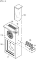
FIG. 1 is a front perspective view of an air purifier according to an embodiment. -
FIG. 2 is a perspective view showing a rear side of an air purifier according to an embodiment. -
FIG. 3 is an exploded perspective view of an air purifier according to an embodiment. -
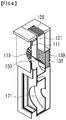
FIG. 4 is a cross-sectional perspective view of an air purifier according to an embodiment taken along line A-A' ofFIG. 1 . -
FIG. 5 is a side view of an air purifier according to an embodiment and a view showing the position of a flow path control member and the flow of air when operating in a purification intensive mode. -
FIG. 6 is a side view of an air purifier according to an embodiment and a view showing the position of a flow path control member and the flow of air when operating in a purification circulation mode. -
FIG. 7 is a side view of an air purifier according to an embodiment and a view showing the position of a flow path control member and the flow of air when operating in a humidifying mode. -
FIG. 8 is a side view of an air purifier according to an embodiment and a view showing the position of a flow path control member and the flow of air when operating in a purification circulation intensive mode. -
FIG. 9 is a side view of an air purifier according to an embodiment and a view showing the position of a flow path control member and the flow of air when operating in a multi-circulation mode. -
FIG. 10 is a side view of an air purifier according to an embodiment and a view showing the position of a flow path control member and the flow of air when operating in a multi-intensive mode. -
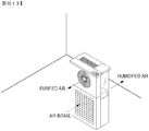
FIG. 11 is a perspective view of an air purifier according to an embodiment and a view showing the flow of air when operating in a purification circulation intensive mode. -
FIG. 12 is a perspective view of the rear side of an air purifier according to an embodiment and a view showing the flow of air when operating in a multi-circulation mode. -
FIG. 13 is a perspective view of an air purifier according to an embodiment and a view showing the flow of air when operating in a multi-intensive mode. - Hereinafter, the present invention will be described in detail with reference to the accompanying drawings.
- Referring to
FIGS. 1 through 4 , an air purifier according to an embodiment of the present invention includes ahousing 100, a plurality ofdischarge ports path control member 150, aguide 160, aninlet 170, afan 180, and acontrol unit 190. In the illustrated embodiment, thehousing 100 has a rectangular parallelepiped shape, but the shape of thehousing 100 is not limited thereto and may be formed in other shapes. Thecontrol unit 190 is located on the upper side of thehousing 100 and performs a function of controlling a mode of the air purifier. - A plurality of
discharge ports housing 100. Although the number of the plurality ofdischarge ports - A
first discharge port 112 is located on the front surface of thehousing 100. Thefirst discharge port 112 is connected to a firstdischarge flow path 111 through which the air introduced from theinlet 170 moves, and thus functions to discharge the air to the outside. When air is discharged through thefirst discharge port 112, the surrounding air of the air purifier can be intensively purified. Accordingly, a user can select thefirst discharge port 112 when intensive and rapid air purification in a narrow space is required. - A
second discharge port 122 is located on the upper side of thehousing 100. Thesecond discharge port 122 is connected to a seconddischarge flow path 121 through which the air introduced from theinlet 170 moves, and thus functions to discharge air to the outside. When air is discharged through thesecond discharge port 122, the air is discharged upward, and convection occurs. The overall air around the air purifier can be circulated. Accordingly, the user may select thesecond discharge port 112 when overall air circulation in a large space is required. - A
third discharge port 132 is located on the rear surface of thehousing 100 opposite to thefirst discharge port 112. Thethird discharge port 132 is connected to a thirddischarge flow path 131 through which the air introduced from theinlet 170 moves, and thus functions to discharge air to the outside. Before the air is discharged through thethird discharge port 132, the air passes through ahumidifying filter 133. The air passing through thehumidifying filter 133 is humidified to increase the humidity of the indoor air. Accordingly, the user may select thethird discharge port 132 in a dry season when the humidity decreases. - The
humidifying filter 133 is seated in awater receiving portion 135 with three open sides. Looking at thewater receiving portion 135, thehumidifying filter 133 is located on one side of the open three sides, and awater tank 134 is located on the other side (seeFIG. 3 ). A check valve (not shown) is located on the lower surface of thewater tank 134, so that when thewater tank 134 is mounted in the air purifier (that is, when thewater tank 134 is seated in the water receiving portion 135), water flows into thewater receiving portion 135 and permeates into thehumidifying filter 133. The air flowing along the thirddischarge flow path 131 passes through thehumidifying filter 133 to become moist air and is discharged to the outside. - The flow path control
member 150 is positioned at a portion where the plurality ofdischarge flow paths intake flow path 171 are in contact with each other, and the possibility of fluid connection is controlled so that air flows along any one or more of the plurality ofdischarge flow paths FIGS. 5 through 7 , the flow path controlmember 150 has a plate shape and rotates to perform a purification intensive mode, a purification circulation mode, a humidifying mode, and the like. - In addition, the flow path control
member 150 may include a plurality ofunits discharge ports intake flow path 171, may be changed by relative rotation between the plurality ofunits FIGS. 8 through 10 , the flow path controlmember 150 includes two units, afirst unit 151 and asecond unit 152, and thefirst unit 151 and thesecond unit 152 are relatively rotated to form an L-shape. The plurality ofunits member 150 may rotate to perform a purification circulation intensive mode, a humidifying intensive mode, a humidifying circulation mode, and the like. - The shape and configuration of the flow path control
member 150 are for closing the plurality ofdischarge flow paths discharge flow paths - As described above, according to the environment of the indoor air, the flow path control
member 150 can flexibly control the plurality ofdischarge flow paths - The
guide 160 is positioned at an inlet portion of the third discharge flow path adjacent to the flow path controlmember 150. - When the humidifying function is not in use, if the air does not flow in the
humidifying filter 133, water may accumulate, and odor may be gradually generated, and air may be introduced from the outside, and thus a filter may be dusty and contaminated. In the present invention, theguide 160 may continuously guide a portion of the air to the thirddischarge flow path 131 even when the thirddischarge flow path 131 is not used, to let the air pass through, thereby preventing odor and contam ination. - The
inlet 170 is a place where indoor air to be purified is introduced into the interior, and the introduced indoor air is purified by a firstfunctional filter 177a, a secondfunctional filter 177b, and the like, and then discharged again. In the illustrated embodiment, theinlet 170, the firstfunctional filter 177a, and the secondfunctional filter 177b are shown to be located on the lower side of thehousing 100, but the present invention is not limited thereto, and theinlet 170, the firstfunctional filter 177a, and the secondfunctional filter 177b may be located anywhere inside thehousing 100. - The first
functional filter 177a and the secondfunctional filter 177b may include a fine dust filter, a deodorizing filter, a HEPA filter, and the like, but may be any various filtering devices as needed. - In the illustrated embodiment, the shape of the first
functional filter 177a and the secondfunctional filter 177b is a rectangular plate shape, but the shape may be formed in other shapes. - The
fan 180 performs a function of introducing and discharging indoor air into the interior of thehousing 100. That is, indoor air is introduced into thehousing 100 through theinlet 170 by the rotation of thefan 180. - The rotation speed of the
fan 180 may be adjusted as needed. That is, thehousing 100 may be rotated at a high speed to increase the flow rate of the indoor air flowing into thehousing 100, or thehousing 100 may be rotated at a low speed to decrease the flow rate. - On the other hand, when the humidifying function is used, water that has leaked or condensed due to the
humidifying filter 133 or the like flows into the electrical parts of the fan 180 (the right side ofFIG. 5 ), which may cause a malfunction. In the air purifier according to the present invention, in order to prevent water from entering afan power member 181, such as when water leaks from thehumidifying filter 133, a fanwaterproof housing 185 having watertightness is placed between a core and blades of thefan 180 and the electrical parts of thefan 180. - The air purifier according to an embodiment of the present invention may perform various modes according to the state or season of indoor air.
- Six modes will be mainly described as examples. Specifically, embodiments in which the flow path control
member 150 is not classified into units but closes a plurality ofdischarge ports member 150 is classified into a plurality ofunits discharge ports - The flow path control
member 150 rotates to close thesecond discharge port 122 and thethird discharge port 132 to perform a purification intensive mode, and closes thefirst discharge port 112 and thethird discharge port 132 to close thefirst discharge port 112 and thesecond discharge port 132, thereby performing a humidifying mode. In a second embodiment, the plurality ofunits member 150 rotate to close thethird discharge port 132, thereby performing a purification circulation intensive mode, to close thesecond discharge port 122, thereby performing a humidifying intensive mode, and to close thefirst discharge portion 112, thereby performing a humidifying circulation mode. - Hereinafter, each mode of the air purifier and its effects will be described in detail with reference to
FIGS. 5 through 13 . - The purification intensive mode will be described with reference to
FIG. 5 . - Here, the air introduced into the
inlet 170 passes through the firstfunctional filter 177a and the secondfunctional filter 177b, and the air flowing along anintake flow path 171 is branched by the flow path controlmember 150 to be directed toward the firstdischarge flow path 111. At this time, air is guided by theguide 160 in the thirddischarge flow path 131 so that air is always passed through thehumidifying filter 133 little by little, thereby preventing odor of thehumidifying filter 133 and preventing contamination. - Air is discharged through the
first discharge port 112. As thefirst discharge port 112 is installed on the front side, the purification intensive mode enables intensive purification at a desired location around the air purifier, thereby enabling intensive indoor circulation of air. In the purification circulation mode to be described later, since thesecond discharge port 122 located on the upper side is used instead of thefirst discharge port 112, it takes time to purify around the air purifier because overall circulation of the air is performed. - Therefore, it is possible to use the purification intensive mode when intensive purification is required in a relatively narrow indoor space.
- The purification circulation mode will be described with reference to
FIG. 6 . - Here, the air introduced into the
inlet 170 passes through the firstfunctional filter 177a and the secondfunctional filter 177b, and the air flowing along theintake flow path 171 is branched by the flow path controlmember 150 to be directed toward the seconddischarge flow path 121. Air is then guided by theguide 160 in the thirddischarge flow path 131 so that air is always passed through thehumidifying filter 133 little by little, thereby preventing odor of thehumidifying filter 133 and preventing contamination. - Air is discharged through the
second discharge port 122. As thesecond discharge port 122 is installed on the upper side, in the purification circulation mode, large indoor circulation occurs that largely circulates the entire indoor space due to a convection phenomenon. The purification concentration mode described above differs in that it is difficult to circulate the entire large indoor space because thesecond discharge port 122 is not used. - Therefore, the purification circulation mode can be used when the air purifying function of a large indoor space is required.
- A humidifying mode will be described with reference to
FIG. 7 . - Here, the air introduced into the
inlet 170 passes through the firstfunctional filter 177a and the secondfunctional filter 177b, and the air flowing along theintake flow path 171 is branched by the flow path controlmember 150 to be directed toward the thirddischarge flow path 131. - Air is discharged through the
third discharge port 132. As thethird discharge port 132 includes ahumidifying filter 133, it can be used when a humidifying function is required. - Therefore, it is possible to use the humidifying mode when the humidifying function is intensively needed as the humidity is low rather than air purification.
- The purification circulation intensive mode will be described with reference to
FIGS. 8 and11 . - Here, the air introduced into the
inlet 170 passes through the firstfunctional filter 177a and the secondfunctional filter 177b, and the air flowing along theintake flow path 171 is branched by the flow path controlmember 150 to be directed toward the firstdischarge flow path 111 and the seconddischarge flow path 121. Air is then guided by theguide 160 in the thirddischarge flow path 131 so that air is always passed through thehumidifying filter 133 little by little, thereby preventing odor of thehumidifying filter 133 and preventing contamination. - Air is discharged through the
first discharge port 112 and thesecond discharge port 122. Thefirst discharge port 112 is installed on the front side to enable intensive indoor circulation, and thesecond discharge port 122 is formed on the upper side, so that large indoor circulation occurs that greatly circulates the entire indoor space due to convection. The purification circulation intensive mode uses the functions of the purification intensive mode and purification circulation mode. - Therefore, when an intensive purification function of a narrow indoor space and a purification function of a large indoor space are required at the same time, the purification circulation intensive mode can be used. In particular, it is useful when there is not a great need for humidified air, such as in spring and summer.
- The humidifying circulation mode will be described with reference to
FIG. 9 and12 . - Here, the air introduced into the
inlet 170 passes through the firstfunctional filter 177a and the secondfunctional filter 177b, and the air flowing along theintake flow path 171 is branched by the flow path controlmember 150 to be directed to the seconddischarge flow path 121 and the thirddischarge flow path 131. - Air is discharged through the
second discharge port 122 and thethird discharge port 132. Thesecond discharge port 122 is formed on the upper side, and as major indoor circulation occurs in the entire indoor space due to a convection phenomenon, it can be used when a humidifying function and an air purifying function are required at the same time. As thethird discharge port 132 includes ahumidifying filter 133, it can be used when a humidifying function is required. The humidifying circulation mode uses the functions of the purification circulation mode and humidifying mode. - Therefore, it is possible to circulate air in a large indoor space and use the humidifying circulation mode when a humidifying function is also required. In particular, it is useful when humidified air is needed, such as in autumn and winter.
- The humidifying concentration mode will be described with reference to
FIGS. 10 and13 . - Here, the air introduced into the
inlet 170 passes through the firstfunctional filter 177a and the secondfunctional filter 177b, and the air flowing along theintake flow path 171 is branched by the flow path controlmember 150 to be directed to the firstdischarge flow path 111 and the thirddischarge flow path 131. - Air is discharged through the
first discharge port 112 and thethird discharge port 132. Thefirst discharge port 112 is formed in the front to intensively purify a narrow indoor space, and thethird discharge port 132 may perform a humidifying function by including thehumidifying filter 133. The humidifying intensive mode uses the functions of the purification intensive mode and the humidifying mode. - Therefore, it is possible to use the humidifying intensive mode when a narrow indoor space is intensively purified and a humidifying function is also required. In particular, it is useful when limited humidified air is needed in a narrow space.
- While the present invention has been particularly shown and described with reference to exemplary embodiments thereof, it will be understood by those of ordinary skill in the art that various changes in form and details may be made therein without departing from the spirit and scope of the present invention as defined by the following claims.
Claims (13)
- An air purifier comprises:an intake flow path (171) through which air introduced from an inlet (170) flows;a flow path control member (150) on the intake flow path (171); anda housing (100),wherein the flow path control member (150) is installed on a flow path between the intake flow path (171) and a plurality of discharge ports (112, 122, 132).
- The air purifier of claim 1, wherein the plurality of discharge ports (112, 122, 132) comprises:a first discharge port (112) formed on one side of the housing (100);a second discharge portion (122) formed on an upper side of the housing (100);a third discharge portion (132) formed on the other side opposite to the one side of the housing (100);a first discharge flow path (111) communicating the first discharge port (112) with the intake flow path (171);a second discharge flow path (121) communicating the second discharge port (122) with the intake flow path (171); anda third discharge flow path (131) communicating the third discharge port (132) with the intake flow path (171),wherein the intake flow path (171) is in communication with any one or more of the first discharge flow path (111), the second discharge flow path (121), and the third discharge flow path (131) by way of the flow path control member (150).
- The air purifier of claim 2, wherein, even when the flow path control member (150) closes the third discharge flow path (131), a guide (160) for guiding air into the third discharge flow path (131) is positioned at an inlet portion of the third discharge flow path (131).
- The air purifier of claim 3, further comprising:a humidifying filter (133) positioned on the third discharge flow path (131);a water receiving portion (135) in which the humidifying filter (133) is seated; anda water tank (134) comprising a check valve in communication with an inside of the water receiving portion (135).
- The air purifier of claim 2, wherein the first discharge portion (112) is positioned at a side surface of the air purifier, and air introduced into the intake flow path (171) is discharged to the first discharge port (112) by the flow path control member (150) so that a purification intensive mode is performed.
- The air purifier of claim 2, wherein air introduced into the intake flow path (171) is discharged to the second discharge port (122) by the flow path control member (150) so that a purification circulation mode is performed.
- The air purifier of claim 4, wherein air introduced into the intake flow path (171) is discharged to the third discharge port (132) by the flow path control member (150) so that a humidifying mode is performed.
- The air purifier of claim 2, wherein the flow path control member (150) comprises a plurality of units (151, 152), and the plurality of discharge ports (112, 122, 132) in communication with the intake flow path (171) are changeable by way of relative rotation between the plurality of units (151, 152).
- The air purifier of claim 8, wherein the flow path control member (150) has an L-shape due to relative rotation of the plurality of units (151, 152) so that the intake flow path (171) is in communication with any two of the first discharge flow path (111), the second discharge flow path (121), and the third discharge flow path (131) by way of the flow path control member (150).
- The air purifier of claim 9, wherein air introduced into the intake flow path (171) is discharged to the first discharge port (112) and the second discharge port (122) by the flow path control member (150) so that a purification circulation intensive mode is performed.
- The air purifier of claim 9, wherein air introduced into the intake flow path (171) is discharged to the second discharge port (122) and the third discharge port (132) by the flow path control member (150) so that a humidifying circulation mode is performed.
- The air purifier of claim 9, wherein air introduced into the intake flow path (171) is discharged to the first discharge port (112) and the third discharge port (132) by the flow path control member (150) so that a humidifying intensive mode is performed.
- The air purifier of claim 1, further comprising a fan (180) positioned on the intake flow path (171), wherein a rotating portion of the fan (180) is sealed with respect to a fan power member (181) of the fan (180) by a fan waterproof housing (185).
Applications Claiming Priority (2)
| Application Number | Priority Date | Filing Date | Title |
|---|---|---|---|
| KR1020180172234A KR102300503B1 (en) | 2018-12-28 | 2018-12-28 | A humidification air purifier comprising a flow passage control member |
| PCT/KR2019/017873 WO2020138813A1 (en) | 2018-12-28 | 2019-12-17 | Air purifier comprising flow path control member |
Publications (4)
| Publication Number | Publication Date |
|---|---|
| EP3904774A1 true EP3904774A1 (en) | 2021-11-03 |
| EP3904774A4 EP3904774A4 (en) | 2022-09-07 |
| EP3904774C0 EP3904774C0 (en) | 2025-02-05 |
| EP3904774B1 EP3904774B1 (en) | 2025-02-05 |
Family
ID=71128278
Family Applications (1)
| Application Number | Title | Priority Date | Filing Date |
|---|---|---|---|
| EP19904105.4A Active EP3904774B1 (en) | 2018-12-28 | 2019-12-17 | Air purifier comprising flow path control member |
Country Status (4)
| Country | Link |
|---|---|
| EP (1) | EP3904774B1 (en) |
| JP (1) | JP7209843B2 (en) |
| KR (1) | KR102300503B1 (en) |
| WO (1) | WO2020138813A1 (en) |
Cited By (2)
| Publication number | Priority date | Publication date | Assignee | Title |
|---|---|---|---|---|
| US20210278096A1 (en) * | 2018-06-29 | 2021-09-09 | Coway Co., Ltd. | Air purifier including bidirectional discharge flow path and method of controlling the same |
| US12584644B2 (en) | 2020-08-14 | 2026-03-24 | Samsung Electronics Co., Ltd. | Air purifier |
Families Citing this family (3)
| Publication number | Priority date | Publication date | Assignee | Title |
|---|---|---|---|---|
| CN113757900B (en) * | 2021-10-08 | 2022-08-30 | 安徽皖华环保设备科技有限公司 | Multifunctional environment-friendly indoor air purification device |
| JP7821098B2 (en) * | 2022-12-22 | 2026-02-26 | 株式会社コロナ | humidifier |
| KR20250099997A (en) * | 2023-12-26 | 2025-07-03 | 코웨이 주식회사 | Air cleaner |
Family Cites Families (17)
| Publication number | Priority date | Publication date | Assignee | Title |
|---|---|---|---|---|
| JPS5824655B2 (en) * | 1978-02-14 | 1983-05-23 | 本田技研工業株式会社 | Hydraulic clutch check valve |
| JP2005172360A (en) | 2003-12-12 | 2005-06-30 | Taisei Corp | Easy-to-clean air conditioner |
| US20070256433A1 (en) * | 2006-05-02 | 2007-11-08 | Bhatti Mohinder S | Portable air conditioner |
| WO2008015851A1 (en) * | 2006-08-03 | 2008-02-07 | Sharp Kabushiki Kaisha | Air cleaner |
| JP4011094B1 (en) * | 2006-08-03 | 2007-11-21 | シャープ株式会社 | Air cleaner |
| BRPI0622203A2 (en) * | 2006-12-22 | 2012-01-03 | Springer Carrier Ltda | window air conditioning unit, and, Method to provide maintenance for a window air conditioning unit |
| KR100988441B1 (en) | 2007-12-04 | 2010-10-18 | 웅진코웨이주식회사 | Air cleaning and humidification unit |
| KR101048202B1 (en) | 2008-11-21 | 2011-07-08 | 동양매직 주식회사 | Combined Air Purifier |
| JP2010243068A (en) | 2009-04-07 | 2010-10-28 | Panasonic Corp | Air purifier with humidification function |
| JP2012068005A (en) | 2010-08-27 | 2012-04-05 | Panasonic Corp | Humidification air cleaner |
| JP5541040B2 (en) | 2010-09-27 | 2014-07-09 | 三洋電機株式会社 | Humidification hot air machine |
| KR101837621B1 (en) * | 2015-12-04 | 2018-03-13 | 코웨이 주식회사 | Air conditioner |
| CN108291728B (en) | 2015-12-02 | 2021-07-13 | 豪威株式会社 | air purifier |
| KR102667526B1 (en) * | 2016-12-07 | 2024-05-22 | 코웨이 주식회사 | Air cleaner with humidification |
| CN110462303A (en) | 2017-04-05 | 2019-11-15 | 夏普株式会社 | Swing leaves and air supply device |
| KR20180131001A (en) * | 2017-05-31 | 2018-12-10 | 주식회사 위닉스 | Air cleaner |
| KR102838131B1 (en) * | 2019-06-17 | 2025-07-25 | 코웨이 주식회사 | Air Cleaner Having Humidifying Function |
-
2018
- 2018-12-28 KR KR1020180172234A patent/KR102300503B1/en active Active
-
2019
- 2019-12-17 WO PCT/KR2019/017873 patent/WO2020138813A1/en not_active Ceased
- 2019-12-17 JP JP2021537895A patent/JP7209843B2/en active Active
- 2019-12-17 EP EP19904105.4A patent/EP3904774B1/en active Active
Cited By (3)
| Publication number | Priority date | Publication date | Assignee | Title |
|---|---|---|---|---|
| US20210278096A1 (en) * | 2018-06-29 | 2021-09-09 | Coway Co., Ltd. | Air purifier including bidirectional discharge flow path and method of controlling the same |
| US12410924B2 (en) * | 2018-06-29 | 2025-09-09 | Coway Co., Ltd. | Air purifier including bidirectional discharge flow path and method of controlling the same |
| US12584644B2 (en) | 2020-08-14 | 2026-03-24 | Samsung Electronics Co., Ltd. | Air purifier |
Also Published As
| Publication number | Publication date |
|---|---|
| EP3904774A4 (en) | 2022-09-07 |
| WO2020138813A1 (en) | 2020-07-02 |
| EP3904774C0 (en) | 2025-02-05 |
| JP2022516106A (en) | 2022-02-24 |
| EP3904774B1 (en) | 2025-02-05 |
| JP7209843B2 (en) | 2023-01-20 |
| KR20200082058A (en) | 2020-07-08 |
| KR102300503B1 (en) | 2021-09-09 |
Similar Documents
| Publication | Publication Date | Title |
|---|---|---|
| EP3904774B1 (en) | Air purifier comprising flow path control member | |
| EP3971487B1 (en) | Air humidification and purification device | |
| KR100988441B1 (en) | Air cleaning and humidification unit | |
| EP3643984A1 (en) | Air purifier including bidirectional fans having different discharge directions | |
| KR200490295Y1 (en) | Wall-installable heat recovery type ventilation device | |
| CN108700313A (en) | Air-conditioning and its control method | |
| KR20070087771A (en) | Ventilation | |
| CN108885023B (en) | Air conditioner and control method thereof | |
| CN215336793U (en) | Device for adjusting humidity | |
| KR101197822B1 (en) | Humidity controlling system | |
| KR20190124298A (en) | Standing air conditioner | |
| KR100531087B1 (en) | Air Purifier Having Ventilating Function | |
| CN108613255B (en) | An indoor air conditioning system | |
| KR101540034B1 (en) | Bypass duct type ventilating device | |
| JP3722144B2 (en) | Heat exchange unit | |
| KR102572207B1 (en) | Multifunctional storage system capable of forming a variable flow path inside | |
| KR20050080286A (en) | Air cleaning system with ventilator | |
| CN217737366U (en) | Lower cabinet machine and air conditioning equipment | |
| CN114046568B (en) | Air treatment device and air conditioner | |
| CN120403073B (en) | Air duct assembly and air conditioner | |
| KR102580539B1 (en) | Air Conditioner | |
| KR20200078042A (en) | Air Cleaner Having Humidifying Function | |
| KR20200134041A (en) | Installable air purifier for fan assembly capable of assembly and detachment | |
| KR102916234B1 (en) | A multifunctional storage system including a recirculation flow passage | |
| KR102714762B1 (en) | An air cleaner capable of drying humidification filter |
Legal Events
| Date | Code | Title | Description |
|---|---|---|---|
| STAA | Information on the status of an ep patent application or granted ep patent |
Free format text: STATUS: THE INTERNATIONAL PUBLICATION HAS BEEN MADE |
|
| PUAI | Public reference made under article 153(3) epc to a published international application that has entered the european phase |
Free format text: ORIGINAL CODE: 0009012 |
|
| STAA | Information on the status of an ep patent application or granted ep patent |
Free format text: STATUS: REQUEST FOR EXAMINATION WAS MADE |
|
| 17P | Request for examination filed |
Effective date: 20210728 |
|
| AK | Designated contracting states |
Kind code of ref document: A1 Designated state(s): AL AT BE BG CH CY CZ DE DK EE ES FI FR GB GR HR HU IE IS IT LI LT LU LV MC MK MT NL NO PL PT RO RS SE SI SK SM TR |
|
| DAV | Request for validation of the european patent (deleted) | ||
| DAX | Request for extension of the european patent (deleted) | ||
| A4 | Supplementary search report drawn up and despatched |
Effective date: 20220805 |
|
| RIC1 | Information provided on ipc code assigned before grant |
Ipc: F24F 13/28 20060101ALI20220801BHEP Ipc: F24F 8/108 20210101ALI20220801BHEP Ipc: F24F 6/00 20060101ALI20220801BHEP Ipc: F24F 13/20 20060101ALI20220801BHEP Ipc: F24F 6/04 20060101ALI20220801BHEP Ipc: F24F 3/16 20210101ALI20220801BHEP Ipc: F24F 13/14 20060101ALI20220801BHEP Ipc: F24F 11/70 20180101ALI20220801BHEP Ipc: F24F 11/00 20180101AFI20220801BHEP |
|
| GRAP | Despatch of communication of intention to grant a patent |
Free format text: ORIGINAL CODE: EPIDOSNIGR1 |
|
| STAA | Information on the status of an ep patent application or granted ep patent |
Free format text: STATUS: GRANT OF PATENT IS INTENDED |
|
| INTG | Intention to grant announced |
Effective date: 20240909 |
|
| GRAS | Grant fee paid |
Free format text: ORIGINAL CODE: EPIDOSNIGR3 |
|
| GRAA | (expected) grant |
Free format text: ORIGINAL CODE: 0009210 |
|
| STAA | Information on the status of an ep patent application or granted ep patent |
Free format text: STATUS: THE PATENT HAS BEEN GRANTED |
|
| AK | Designated contracting states |
Kind code of ref document: B1 Designated state(s): AL AT BE BG CH CY CZ DE DK EE ES FI FR GB GR HR HU IE IS IT LI LT LU LV MC MK MT NL NO PL PT RO RS SE SI SK SM TR |
|
| REG | Reference to a national code |
Ref country code: GB Ref legal event code: FG4D |
|
| REG | Reference to a national code |
Ref country code: CH Ref legal event code: EP |
|
| REG | Reference to a national code |
Ref country code: IE Ref legal event code: FG4D |
|
| REG | Reference to a national code |
Ref country code: DE Ref legal event code: R096 Ref document number: 602019065664 Country of ref document: DE |
|
| U01 | Request for unitary effect filed |
Effective date: 20250218 |
|
| U07 | Unitary effect registered |
Designated state(s): AT BE BG DE DK EE FI FR IT LT LU LV MT NL PT RO SE SI Effective date: 20250224 |
|
| PG25 | Lapsed in a contracting state [announced via postgrant information from national office to epo] |
Ref country code: RS Free format text: LAPSE BECAUSE OF FAILURE TO SUBMIT A TRANSLATION OF THE DESCRIPTION OR TO PAY THE FEE WITHIN THE PRESCRIBED TIME-LIMIT Effective date: 20250505 |
|
| PG25 | Lapsed in a contracting state [announced via postgrant information from national office to epo] |
Ref country code: PL Free format text: LAPSE BECAUSE OF FAILURE TO SUBMIT A TRANSLATION OF THE DESCRIPTION OR TO PAY THE FEE WITHIN THE PRESCRIBED TIME-LIMIT Effective date: 20250205 |
|
| PG25 | Lapsed in a contracting state [announced via postgrant information from national office to epo] |
Ref country code: ES Free format text: LAPSE BECAUSE OF FAILURE TO SUBMIT A TRANSLATION OF THE DESCRIPTION OR TO PAY THE FEE WITHIN THE PRESCRIBED TIME-LIMIT Effective date: 20250205 |
|
| PG25 | Lapsed in a contracting state [announced via postgrant information from national office to epo] |
Ref country code: IS Free format text: LAPSE BECAUSE OF FAILURE TO SUBMIT A TRANSLATION OF THE DESCRIPTION OR TO PAY THE FEE WITHIN THE PRESCRIBED TIME-LIMIT Effective date: 20250605 Ref country code: NO Free format text: LAPSE BECAUSE OF FAILURE TO SUBMIT A TRANSLATION OF THE DESCRIPTION OR TO PAY THE FEE WITHIN THE PRESCRIBED TIME-LIMIT Effective date: 20250505 |
|
| PG25 | Lapsed in a contracting state [announced via postgrant information from national office to epo] |
Ref country code: HR Free format text: LAPSE BECAUSE OF FAILURE TO SUBMIT A TRANSLATION OF THE DESCRIPTION OR TO PAY THE FEE WITHIN THE PRESCRIBED TIME-LIMIT Effective date: 20250205 |
|
| PG25 | Lapsed in a contracting state [announced via postgrant information from national office to epo] |
Ref country code: GR Free format text: LAPSE BECAUSE OF FAILURE TO SUBMIT A TRANSLATION OF THE DESCRIPTION OR TO PAY THE FEE WITHIN THE PRESCRIBED TIME-LIMIT Effective date: 20250506 |
|
| PG25 | Lapsed in a contracting state [announced via postgrant information from national office to epo] |
Ref country code: SM Free format text: LAPSE BECAUSE OF FAILURE TO SUBMIT A TRANSLATION OF THE DESCRIPTION OR TO PAY THE FEE WITHIN THE PRESCRIBED TIME-LIMIT Effective date: 20250205 |
|
| PG25 | Lapsed in a contracting state [announced via postgrant information from national office to epo] |
Ref country code: CZ Free format text: LAPSE BECAUSE OF FAILURE TO SUBMIT A TRANSLATION OF THE DESCRIPTION OR TO PAY THE FEE WITHIN THE PRESCRIBED TIME-LIMIT Effective date: 20250205 |
|
| PG25 | Lapsed in a contracting state [announced via postgrant information from national office to epo] |
Ref country code: SK Free format text: LAPSE BECAUSE OF FAILURE TO SUBMIT A TRANSLATION OF THE DESCRIPTION OR TO PAY THE FEE WITHIN THE PRESCRIBED TIME-LIMIT Effective date: 20250205 |
|
| PLBE | No opposition filed within time limit |
Free format text: ORIGINAL CODE: 0009261 |
|
| STAA | Information on the status of an ep patent application or granted ep patent |
Free format text: STATUS: NO OPPOSITION FILED WITHIN TIME LIMIT |
|
| 26N | No opposition filed |
Effective date: 20251106 |
|
| U20 | Renewal fee for the european patent with unitary effect paid |
Year of fee payment: 7 Effective date: 20251223 |