EP3904242A1 - Apparatus for lengthwise moving of rod-like articles - Google Patents
Apparatus for lengthwise moving of rod-like articles Download PDFInfo
- Publication number
- EP3904242A1 EP3904242A1 EP20171883.0A EP20171883A EP3904242A1 EP 3904242 A1 EP3904242 A1 EP 3904242A1 EP 20171883 A EP20171883 A EP 20171883A EP 3904242 A1 EP3904242 A1 EP 3904242A1
- Authority
- EP
- European Patent Office
- Prior art keywords
- rod
- articles
- roller
- conveyed
- working surface
- Prior art date
- Legal status (The legal status is an assumption and is not a legal conclusion. Google has not performed a legal analysis and makes no representation as to the accuracy of the status listed.)
- Withdrawn
Links
Images


Classifications
-
- B—PERFORMING OPERATIONS; TRANSPORTING
- B65—CONVEYING; PACKING; STORING; HANDLING THIN OR FILAMENTARY MATERIAL
- B65G—TRANSPORT OR STORAGE DEVICES, e.g. CONVEYORS FOR LOADING OR TIPPING, SHOP CONVEYOR SYSTEMS OR PNEUMATIC TUBE CONVEYORS
- B65G47/00—Article or material-handling devices associated with conveyors; Methods employing such devices
- B65G47/74—Feeding, transfer, or discharging devices of particular kinds or types
- B65G47/84—Star-shaped wheels or devices having endless travelling belts or chains, the wheels or devices being equipped with article-engaging elements
- B65G47/846—Star-shaped wheels or wheels equipped with article-engaging elements
-
- A—HUMAN NECESSITIES
- A24—TOBACCO; CIGARS; CIGARETTES; SIMULATED SMOKING DEVICES; SMOKERS' REQUISITES
- A24C—MACHINES FOR MAKING CIGARS OR CIGARETTES
- A24C5/00—Making cigarettes; Making tipping materials for, or attaching filters or mouthpieces to, cigars or cigarettes
- A24C5/47—Attaching filters or mouthpieces to cigars or cigarettes, e.g. inserting filters into cigarettes or their mouthpieces
- A24C5/478—Transport means for filter- or cigarette-rods in view of their assembling
-
- B—PERFORMING OPERATIONS; TRANSPORTING
- B65—CONVEYING; PACKING; STORING; HANDLING THIN OR FILAMENTARY MATERIAL
- B65G—TRANSPORT OR STORAGE DEVICES, e.g. CONVEYORS FOR LOADING OR TIPPING, SHOP CONVEYOR SYSTEMS OR PNEUMATIC TUBE CONVEYORS
- B65G15/00—Conveyors having endless load-conveying surfaces, i.e. belts and like continuous members, to which tractive effort is transmitted by means other than endless driving elements of similar configuration
- B65G15/30—Belts or like endless load-carriers
- B65G15/32—Belts or like endless load-carriers made of rubber or plastics
- B65G15/42—Belts or like endless load-carriers made of rubber or plastics having ribs, ridges, or other surface projections
-
- B—PERFORMING OPERATIONS; TRANSPORTING
- B65—CONVEYING; PACKING; STORING; HANDLING THIN OR FILAMENTARY MATERIAL
- B65G—TRANSPORT OR STORAGE DEVICES, e.g. CONVEYORS FOR LOADING OR TIPPING, SHOP CONVEYOR SYSTEMS OR PNEUMATIC TUBE CONVEYORS
- B65G47/00—Article or material-handling devices associated with conveyors; Methods employing such devices
- B65G47/74—Feeding, transfer, or discharging devices of particular kinds or types
- B65G47/82—Rotary or reciprocating members for direct action on articles or materials, e.g. pushers, rakes, shovels
-
- A—HUMAN NECESSITIES
- A47—FURNITURE; DOMESTIC ARTICLES OR APPLIANCES; COFFEE MILLS; SPICE MILLS; SUCTION CLEANERS IN GENERAL
- A47G—HOUSEHOLD OR TABLE EQUIPMENT
- A47G21/00—Table-ware
- A47G21/18—Drinking straws or the like
- A47G21/189—Drinking straws or the like telescoping
-
- B—PERFORMING OPERATIONS; TRANSPORTING
- B65—CONVEYING; PACKING; STORING; HANDLING THIN OR FILAMENTARY MATERIAL
- B65G—TRANSPORT OR STORAGE DEVICES, e.g. CONVEYORS FOR LOADING OR TIPPING, SHOP CONVEYOR SYSTEMS OR PNEUMATIC TUBE CONVEYORS
- B65G2201/00—Indexing codes relating to handling devices, e.g. conveyors, characterised by the type of product or load being conveyed or handled
- B65G2201/02—Articles
- B65G2201/0226—Cigarettes
Definitions
- the object of the invention is an apparatus for lengthwise moving of rod-like articles.
- straws which are usually made of plastic or paper are used to drink various kinds of beverages. These may be both one-part and two-part straws, straight straws or bent straws. Two-part straws usually have in their structure a lock connecting both parts so that after inserting one part into the other a beverage may be consumed with an already assembled straw without a risk that the connection will be leaky. In order to assemble a two-part straw, at least one of the straws has to be moved lengthwise, towards the other so that the smaller straw enters the larger straw.
- Apparatuses for lengthwise moving of the rod-like articles for example during the assembly of the telescopic straws or for lengthwise moving of the tobacco industry's rod-like articles on the transferring drum, are known in the prior art.
- the document EP 0 276 025 disclosed a method for assembling a telescopic straw on a conveyor belt on which the straws are moved lengthwise in order to inspect and pack separately assembled straws into a foil.
- the document JP03827769 disclosed an apparatus for assembling a telescopic straw of two parts which are placed in grooves of a conveyor drum.
- a part of the straw with a greater diameter is put onto the straw with a smaller diameter by means of a pusher whose lengthwise motion is forced by a cam.
- the publication EP 3 384 787 disclosed an apparatus for lengthwise moving of the rod-like articles from the rod maker machine to the receiving drum.
- a rod after cutting it of a continuous rod, is moved by means of rollers situated right behind a cutting head and transferred lengthwise into a groove on the receiving drum on which the moving direction is changed from lengthwise to transverse.
- the publication US 3 791 507 shows an apparatus for lengthwise moving of the rod-like articles in grooves of a transferring drum by means of the vacuum supplied to holes situated in the bottom of the groove.
- the object of the invention is an apparatus for lengthwise moving of rod-like articles comprising a conveyor provided with pockets adapted to convey the rod-like articles situated transversely to the conveying direction.
- the apparatus further comprises a rotational element adapted to lengthwise moving of the conveyed rod-like articles in the conveyor pockets, and situated tangentially to the circumferential surface of the conveyed rod-like articles.
- the apparatus according to the invention is characterised in that the rotational element has the shape of a roller with a concave working surface adapted to come into contact with the outside circumferential surface of the conveyed rod-like articles.
- the apparatus according to the invention is characterised in that the concavity of the roller's working surface has a shape selected from a group comprising a section of: a circle, an ellipse, a one-sheeted hyperboloid, a parabola.
- the apparatus according to the invention is characterised in that the concave working surface is adapted so that it remains in contact with at least two adjacent rod-like articles being conveyed.
- the apparatus according to the invention is characterised in that the concave working surface is adapted so that it remains in contact with at least three adjacent rod-like articles being conveyed.
- the apparatus according to the invention is characterised in that the rotational element is situated at an angle to the rotational axis of the conveyor and/or the longitudinal axis of the rod-like article.
- the apparatus according to the invention is characterised in that the angles at which the rotational element is situated range between 5 and 175 degrees.
- the apparatus according to the invention is characterised in that the working surface of the rotational element is made of a material selected from a group comprising: rubber, caoutchouc, spongy material, plastic, metal.
- the object of the invention is further a method for moving the rod-like articles comprising steps wherein: the rod-like articles are fed to the conveyor pockets, whereas the rod-like articles are placed into the conveyor pockets transversely to the conveying direction. Furthermore, the rod-like articles are conveyed on the conveyor towards the rotational element situated tangentially with the working surface to the outside surface of the conveyed articles.
- the method is characterised in that by means of the rotational element in the form of the roller with the concave working surface adapted to come into contact with the outside circumferential surface of the articles being conveyed, the rod-like articles are moved lengthwise in the conveyor pockets from a first position to a second position.
- the method according to the invention is characterised in that simultaneously at least two adjacent conveyed rod-like articles are moved lengthwise.
- An advantage of the invention is its great effectiveness as compared to known solutions from the prior art, and the simplicity of its structure. Furthermore, the rod-like articles are moved lengthwise in a very simple, fast and gentle way so that they are not exposed to deformation and damage.
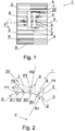
- Fig. 1 shows an apparatus 1 for lengthwise moving of rod-like articles S in the first embodiment in a top view.
- the term of rod-like articles is to be understood as referring to continuous rods, straws, rods and other cylinder-shaped articles.
- the rod-like articles S are placed in pockets 2 situated on the circumferential surface of a conveyor 3 which in this case is a conveying drum.
- the rod-like articles S are placed in the pockets 2 in a position A which in this embodiment is situated on the right side of the drum.
- the article S in the position A is substantially pushed close to the edge 4 of the drum 3.
- the rod-like articles S one after another come into contact with the working surface 7 of a rotational element 20.
- the rotational element 20 for lengthwise moving of the rod-like articles S has the shape of a roller 6 as shown in Fig. 1 , but it may also have the shape of a roller or another rotational element having a working surface with a defined shape which may come into contact with the rod-like articles.
- the term of defined shape is substantially to be understood as referring to a surface which does not substantially change its shape in contact with the rod-like articles. It is acceptable to make such rotational element of rubber or sponge where in contact with the rod-like articles the outline of the entire working surface will remain unchanged, and such deformable rollers which take the conveyor's shape under an adequate pressure and adapt their shape to the surface of the rod-like articles conveyed on the conveyor.
- the rotational element 20 in the form of the roller 6 is situated above the drum 3 immovably relative to the drum 3, with the possibility of rotation around its axis of rotation Y.
- the direction of lengthwise movement of the rod-like articles along their axis Y depends on the directions of rotation of the roller 6.
- Fig. 1 shows the roller 6 during a rotation around the axis Z in the direction U.
- the rotational motion of the roller 6 will cause a lengthwise movement of the rod-like article S from the edge 4 towards the edge 5.
- the length of movement of the rod-like article S in the pocket 2 depends on the rotational speed of the roller 6 and on the time in which the rod-like article S remains in contact with the working surface 7 of the roller 6.
- the time of contact of the rod-like articles S with the roller 6 depends on the length of the working surface 7 and on the rotational speed of the drum 3.
- the length of movement of the rod-like article S in the pockets 2 may be also adjusted by varying the rotational speed of the roller 6. At the moment when the rod-like articles S lose contact with the working surface 7 they are at the position B on the drum 3.
- a change in position from the position A to the position B and the lengthwise axial motion of the rod-like articles S may be used for example for scanning and quality inspection of the outside surface of the rod-like article S by means of a scanning device 8.
- An advantage of the apparatus 1 is the possibility to put the rod-like article S into rotational motion around the axis Y and simultaneously into lengthwise axial motion. During such motion, the article S may be inspected over the entire length and over the entire circumferential surface.
- the roller 6 is situated tangentially to the outside surface of the rod-like articles S placed in the pockets 2, substantially perpendicular to the axis Y of the rod-like articles S and to the axis of rotation X of the drum 3.
- Fig. 2 shows the apparatus 1 for lengthwise moving of the rod-like articles S in the first embodiment in a side view in which it can be seen that the roller 6 is tangentially situated to the outside surface of the rod-like articles S conveyed on the drum 3.
- a tangential situation of the roller 6 is to be understood as such situation of the roller 6 relative to the conveyed rod-like articles S wherein the working surface 7 remains in contact with at least two rod-like articles S conveyed in the adjacent pockets 2.
- a preferred solution is such situation of the roller 6 relative to the conveyed rod-like articles S wherein the working surface 7 of the roller 6 remains in contact with at least three adjacent rod-like articles S.
- the term of contact of the working surface 7 of the roller 6 with the rod-like article is to be understood as a physical contact of the working surface 7 of the roller 6 with a point or a section which is situated on the circumferential surface of the rod-like article S farthest from the bottom of the pocket 2. In such contact, there is a friction between the outside surface of the rod-like article S and the working surface 7 of the roller 6.
- the roller 6 remains in contact with four rod-like articles S1, S2, S3, S4 at the points P1, P2, P3, P4, respectively.
- the roller 6 Since in this embodiment the roller 6 is situated substantially perpendicular with its longitudinal axis Z to the longitudinal axis Y of the rod-like articles S and to the axis of rotation X of the drum 3, the shape of the working surface 7 of the roller 6 will have a concavity 9 with a radius R2.
- the value of the radius R2 will be equal to the value of the drum radius R1 increased by the value of the parameter H, which was shown in detail in Fig. 3 in which, in magnification, a fragment of the roller 6 and of the conveying drum 3 together with the rod-like article S can be seen.
- the parameter H defines the height to which the rod-like article S protrudes with its circumference above the circumferential surface 10 of the drum 3.
- the value H will be different depending on the kind of the rod-like article S.
- the concavity 9 occurs at a point where at least a part of lateral surface of the roller 6 is situated closer to the rotational axis Y of the roller 6 than its end edges.
- Fig. 4 shows the apparatus 1 for lengthwise moving of the rod-like articles S in the second embodiment in a top view in which the roller 6' is situated at an angle ⁇ to the rotational axis X of the drum 3 and to the longitudinal axis Y of the rod-like articles S.
- roller 6 In such situation of the roller 6 relative to the axes X and Y, its working surface 7' will have a curvature with the shape of an elliptic section or a parabola, or the roller 6' itself will have the shape of a one-sheeted hyperboloid section.
- This shape depends on the angle ⁇ at which the roller 6' is situated relative to the axis X and/or Y and on the shape of the element conveying the rod-like articles S at a place where the articles are tangential to the working surface 7'.
- the roller 6' is situated at the angle ⁇ which may be 1-89°, preferably 25-65°, relative to the axis X.
- Fig. 5 shows the apparatus for lengthwise moving of the rod-like articles S in another embodiment in a perspective view.
- the apparatus 1 for lengthwise moving of the rod-like articles S for the purpose of positioning of the rod-like articles S containing a ferromagnetic insert 10.
- the roller 6' by rotating in the direction U around its longitudinal axis Z, lengthwise moves the articles S which after reaching the target position partially protrude outside the pocket 2.
- the portion of the article S protruding outside the pocket 2 is brought into the area of operation of the magnetic field generated by the apparatus 11, as a result of which the rod-like articles S containing the ferromagnetic insert 10 are adequately positioned.
- a conveying apparatus in the above embodiments is the drum 3, however, it is possible to convey and lengthwise move the articles S on a belt 13 conveying a single layer of the articles S placed one after another in the pockets 2, which was shown in Fig.6 .
- the belt 13 may be also replaced with a chain provided with pockets adapted to receive the articles S.
- the apparatus 1 is provided with the roller 6 whose shape resembles a truncated cone with a concave lateral surface.
- the roller 6" is situated perpendicular to the longitudinal axis Y of the conveyed articles S, it may be also situated at an angle.
- the belt 13 is guided on a roller 14 and takes a shape corresponding to circumferential surface of the roller 14.
- the roller 6" has a working surface 7" which substantially reflects the shape which the belt 13 takes on the roller 14 at the place of contact of the roller 6" with the articles S.
- the belt 13 may also be guided on a guide with an adequate curvature.
- the curvature shape and angle should enable the moving roller 6" to remain tangential with its working surface 7" to at least three adjacent rod-like articles S.
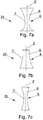
- the roller 6, 6', 6" will have the concave working surface 7, 7', 7" with a shape of a one-sheeted hyperboloid section, an elliptic section or a paraboloidal section. Examples of shapes of the concavity 9 of the working surface 7 of the roller 6 were shown in Figs. 7a, 7b, 7c .
Landscapes
- Engineering & Computer Science (AREA)
- Mechanical Engineering (AREA)
- Attitude Control For Articles On Conveyors (AREA)
Abstract
Description
- The object of the invention is an apparatus for lengthwise moving of rod-like articles.
- In the food industry, straws which are usually made of plastic or paper are used to drink various kinds of beverages. These may be both one-part and two-part straws, straight straws or bent straws. Two-part straws usually have in their structure a lock connecting both parts so that after inserting one part into the other a beverage may be consumed with an already assembled straw without a risk that the connection will be leaky. In order to assemble a two-part straw, at least one of the straws has to be moved lengthwise, towards the other so that the smaller straw enters the larger straw.
- In the tobacco industry, there are used apparatuses for lengthwise moving of the rod-like articles, for example during a transfer from a rod maker machine to a receiving drum, or for moving in grooves of a transferring drum, for example for the purpose of inspection or assembly of a segment filter.
- Apparatuses for lengthwise moving of the rod-like articles, for example during the assembly of the telescopic straws or for lengthwise moving of the tobacco industry's rod-like articles on the transferring drum, are known in the prior art.
- The document
EP 0 276 025 , disclosed a method for assembling a telescopic straw on a conveyor belt on which the straws are moved lengthwise in order to inspect and pack separately assembled straws into a foil. - The document
JP03827769 - The
publication EP 3 384 787 , disclosed an apparatus for lengthwise moving of the rod-like articles from the rod maker machine to the receiving drum. A rod, after cutting it of a continuous rod, is moved by means of rollers situated right behind a cutting head and transferred lengthwise into a groove on the receiving drum on which the moving direction is changed from lengthwise to transverse. - The publication
US 3 791 507 shows an apparatus for lengthwise moving of the rod-like articles in grooves of a transferring drum by means of the vacuum supplied to holes situated in the bottom of the groove. As a result of the vacuum supplied to the holes in an adequate sequence, a segment situated in the groove will start moving lengthwise towards the hole to which the vacuum will be supplied. - The object of the invention is an apparatus for lengthwise moving of rod-like articles comprising a conveyor provided with pockets adapted to convey the rod-like articles situated transversely to the conveying direction. The apparatus further comprises a rotational element adapted to lengthwise moving of the conveyed rod-like articles in the conveyor pockets, and situated tangentially to the circumferential surface of the conveyed rod-like articles. The apparatus according to the invention is characterised in that the rotational element has the shape of a roller with a concave working surface adapted to come into contact with the outside circumferential surface of the conveyed rod-like articles.
- The apparatus according to the invention is characterised in that the concavity of the roller's working surface has a shape selected from a group comprising a section of: a circle, an ellipse, a one-sheeted hyperboloid, a parabola.
- The apparatus according to the invention is characterised in that the concave working surface is adapted so that it remains in contact with at least two adjacent rod-like articles being conveyed.
- The apparatus according to the invention is characterised in that the concave working surface is adapted so that it remains in contact with at least three adjacent rod-like articles being conveyed.
- The apparatus according to the invention is characterised in that the rotational element is situated at an angle to the rotational axis of the conveyor and/or the longitudinal axis of the rod-like article.
- The apparatus according to the invention is characterised in that the angles at which the rotational element is situated range between 5 and 175 degrees.
- The apparatus according to the invention is characterised in that the working surface of the rotational element is made of a material selected from a group comprising: rubber, caoutchouc, spongy material, plastic, metal.
- The object of the invention is further a method for moving the rod-like articles comprising steps wherein: the rod-like articles are fed to the conveyor pockets, whereas the rod-like articles are placed into the conveyor pockets transversely to the conveying direction. Furthermore, the rod-like articles are conveyed on the conveyor towards the rotational element situated tangentially with the working surface to the outside surface of the conveyed articles. The method is characterised in that by means of the rotational element in the form of the roller with the concave working surface adapted to come into contact with the outside circumferential surface of the articles being conveyed, the rod-like articles are moved lengthwise in the conveyor pockets from a first position to a second position.
- The method according to the invention is characterised in that simultaneously at least two adjacent conveyed rod-like articles are moved lengthwise.
- An advantage of the invention is its great effectiveness as compared to known solutions from the prior art, and the simplicity of its structure. Furthermore, the rod-like articles are moved lengthwise in a very simple, fast and gentle way so that they are not exposed to deformation and damage.
- The object of the invention was presented in detail in a preferred embodiment in a drawing in which:
-
Fig. 1 shows an apparatus for lengthwise moving of rod-like articles in the first embodiment in a top view; -
Fig. 2 shows the apparatus for lengthwise moving of the rod-like articles in the first embodiment in a side view; -
Fig. 3 shows an enlarged fragment of the apparatus for lengthwise moving of the rod-like articles in the first embodiment in a side view; -
Fig. 4 shows the apparatus for lengthwise moving of the rod-like articles in the second embodiment in a top view; -
Fig.5 shows the apparatus for lengthwise moving of the rod-like articles in another embodiment in a perspective view; -
Fig.6 shows the apparatus for lengthwise moving of the rod-like articles in another embodiment in a side view; -
Fig. 7a shows the roller of the apparatus for lengthwise moving of the rod-like articles with a concave elliptic working surface, -
Fig. 7b shows the roller of the apparatus for lengthwise moving of the rod-like articles with a conical shape and a concave working surface, -
Fig. 7c shows the roller of the apparatus for lengthwise moving of the rod-like articles with the shape of one-sheeted hyperboloid. -
Fig. 1 shows anapparatus 1 for lengthwise moving of rod-like articles S in the first embodiment in a top view. The term of rod-like articles is to be understood as referring to continuous rods, straws, rods and other cylinder-shaped articles. The rod-like articles S are placed inpockets 2 situated on the circumferential surface of aconveyor 3 which in this case is a conveying drum. The rod-like articles S are placed in thepockets 2 in a position A which in this embodiment is situated on the right side of the drum. The article S in the position A is substantially pushed close to theedge 4 of thedrum 3. During a rotation of thedrum 3 in the direction T around the axis X, the rod-like articles S one after another come into contact with theworking surface 7 of arotational element 20. Therotational element 20 for lengthwise moving of the rod-like articles S has the shape of aroller 6 as shown inFig. 1 , but it may also have the shape of a roller or another rotational element having a working surface with a defined shape which may come into contact with the rod-like articles. The term of defined shape is substantially to be understood as referring to a surface which does not substantially change its shape in contact with the rod-like articles. It is acceptable to make such rotational element of rubber or sponge where in contact with the rod-like articles the outline of the entire working surface will remain unchanged, and such deformable rollers which take the conveyor's shape under an adequate pressure and adapt their shape to the surface of the rod-like articles conveyed on the conveyor. Therotational element 20 in the form of theroller 6 is situated above thedrum 3 immovably relative to thedrum 3, with the possibility of rotation around its axis of rotation Y. - At the moment when the rod-like articles S come into contact with the
working surface 7 of theroller 6 they are put into rotational motion around their longitudinal axis Y. It will be caused by the friction occurring between theworking surface 7 of theroller 6 and the outside surface of the rod-like article S, and the rotational motion of thedrum 3 and of the rod-like articles S situated in itspockets 2. The rotational motion of thedrum 3 itself will cause a rotational motion of the rod-like articles S situated in thepockets 2 around their longitudinal axis Y. Putting theroller 6 into rotational motion around the axis of rotation Z by means of a drive unit (not shown in the figure) will cause that the rod-like articles S will be additionally put into lengthwise axial motion. The direction of lengthwise movement of the rod-like articles along their axis Y depends on the directions of rotation of theroller 6.Fig. 1 shows theroller 6 during a rotation around the axis Z in the direction U. The rotational motion of theroller 6 will cause a lengthwise movement of the rod-like article S from theedge 4 towards theedge 5. The length of movement of the rod-like article S in thepocket 2 depends on the rotational speed of theroller 6 and on the time in which the rod-like article S remains in contact with theworking surface 7 of theroller 6. Furthermore, the time of contact of the rod-like articles S with theroller 6 depends on the length of theworking surface 7 and on the rotational speed of thedrum 3. The length of movement of the rod-like article S in thepockets 2 may be also adjusted by varying the rotational speed of theroller 6. At the moment when the rod-like articles S lose contact with theworking surface 7 they are at the position B on thedrum 3. - A change in position from the position A to the position B and the lengthwise axial motion of the rod-like articles S may be used for example for scanning and quality inspection of the outside surface of the rod-like article S by means of a
scanning device 8. An advantage of theapparatus 1 is the possibility to put the rod-like article S into rotational motion around the axis Y and simultaneously into lengthwise axial motion. During such motion, the article S may be inspected over the entire length and over the entire circumferential surface. - In this embodiment, the
roller 6 is situated tangentially to the outside surface of the rod-like articles S placed in thepockets 2, substantially perpendicular to the axis Y of the rod-like articles S and to the axis of rotation X of thedrum 3. -
Fig. 2 shows theapparatus 1 for lengthwise moving of the rod-like articles S in the first embodiment in a side view in which it can be seen that theroller 6 is tangentially situated to the outside surface of the rod-like articles S conveyed on thedrum 3. - A tangential situation of the
roller 6 is to be understood as such situation of theroller 6 relative to the conveyed rod-like articles S wherein the workingsurface 7 remains in contact with at least two rod-like articles S conveyed in theadjacent pockets 2. A preferred solution is such situation of theroller 6 relative to the conveyed rod-like articles S wherein the workingsurface 7 of theroller 6 remains in contact with at least three adjacent rod-like articles S. - The term of contact of the working
surface 7 of theroller 6 with the rod-like article is to be understood as a physical contact of the workingsurface 7 of theroller 6 with a point or a section which is situated on the circumferential surface of the rod-like article S farthest from the bottom of thepocket 2. In such contact, there is a friction between the outside surface of the rod-like article S and the workingsurface 7 of theroller 6. InFig. 2 , theroller 6 remains in contact with four rod-like articles S1, S2, S3, S4 at the points P1, P2, P3, P4, respectively. Since in this embodiment theroller 6 is situated substantially perpendicular with its longitudinal axis Z to the longitudinal axis Y of the rod-like articles S and to the axis of rotation X of thedrum 3, the shape of the workingsurface 7 of theroller 6 will have aconcavity 9 with a radius R2. The value of the radius R2 will be equal to the value of the drum radius R1 increased by the value of the parameter H, which was shown in detail inFig. 3 in which, in magnification, a fragment of theroller 6 and of the conveyingdrum 3 together with the rod-like article S can be seen. - The parameter H defines the height to which the rod-like article S protrudes with its circumference above the
circumferential surface 10 of thedrum 3. In this case, the radius R2 of theconcavity 9 of theroller 6 will be equal to R2 = R1 + H. - The value H will be different depending on the kind of the rod-like article S.
- The
concavity 9 occurs at a point where at least a part of lateral surface of theroller 6 is situated closer to the rotational axis Y of theroller 6 than its end edges. -
Fig. 4 shows theapparatus 1 for lengthwise moving of the rod-like articles S in the second embodiment in a top view in which the roller 6' is situated at an angle α to the rotational axis X of thedrum 3 and to the longitudinal axis Y of the rod-like articles S. - In such situation of the
roller 6 relative to the axes X and Y, its working surface 7' will have a curvature with the shape of an elliptic section or a parabola, or the roller 6' itself will have the shape of a one-sheeted hyperboloid section. - This shape depends on the angle α at which the roller 6' is situated relative to the axis X and/or Y and on the shape of the element conveying the rod-like articles S at a place where the articles are tangential to the working surface 7'. The roller 6' is situated at the angle α which may be 1-89°, preferably 25-65°, relative to the axis X.
-
Fig. 5 shows the apparatus for lengthwise moving of the rod-like articles S in another embodiment in a perspective view. In this embodiment, there was shown one of the methods for using theapparatus 1 for lengthwise moving of the rod-like articles S for the purpose of positioning of the rod-like articles S containing aferromagnetic insert 10. The roller 6', by rotating in the direction U around its longitudinal axis Z, lengthwise moves the articles S which after reaching the target position partially protrude outside thepocket 2. The portion of the article S protruding outside thepocket 2 is brought into the area of operation of the magnetic field generated by theapparatus 11, as a result of which the rod-like articles S containing theferromagnetic insert 10 are adequately positioned. At the bottom of thepockets 2 over the whole or a part of the length as shown inFig. 5 , there may be situatedholes 12 supplying the vacuum which keeps the articles S in the pockets. Such vacuum may be shut off for the time of moving of the article S in thepocket 2 and/or for the time of positioning in the area of operation of the magnetic field. - A conveying apparatus in the above embodiments is the
drum 3, however, it is possible to convey and lengthwise move the articles S on abelt 13 conveying a single layer of the articles S placed one after another in thepockets 2, which was shown inFig.6 . Thebelt 13 may be also replaced with a chain provided with pockets adapted to receive the articles S. - In this embodiment, the
apparatus 1 is provided with theroller 6 whose shape resembles a truncated cone with a concave lateral surface. Theroller 6" is situated perpendicular to the longitudinal axis Y of the conveyed articles S, it may be also situated at an angle. Thebelt 13 is guided on aroller 14 and takes a shape corresponding to circumferential surface of theroller 14. Theroller 6" has a workingsurface 7" which substantially reflects the shape which thebelt 13 takes on theroller 14 at the place of contact of theroller 6" with the articles S. Instead of theroller 14, thebelt 13 may also be guided on a guide with an adequate curvature. The curvature shape and angle should enable the movingroller 6" to remain tangential with its workingsurface 7" to at least three adjacent rod-like articles S. - Depending on the shape of conveying surface of the
drum 3 or of thebelt 13 at the place of contact with the movingroller roller concave working surface concavity 9 of the workingsurface 7 of theroller 6 were shown inFigs. 7a, 7b, 7c .
Claims (9)
- Apparatus (1) for lengthwise moving of rod-like articles (S) comprising
a conveyor (3) provided with pockets (2) adapted to convey the rod-like articles (S) situated transversely to the conveying direction;
a rotational element (20) adapted to lengthwise moving of the conveyed rod-like articles (S) in the conveyor (3) pockets (2), and situated tangentially to the circumferential surface of the conveyed rod-like articles (S),
characterised in that
the rotational element (20) has the shape of a roller (6, 6', 6") with a concave working surface (7) adapted to come into contact with the outside circumferential surface of the conveyed rod-like articles (S). - Apparatus as in claim 1 characterised in that the concavity (9) of the working surface (7) of the roller (6, 6', 6") has a shape selected from a group comprising a section of: a circle, an ellipse, a one-sheeted hyperboloid, a parabola.
- Apparatus as in any of the claims 1 to 2 characterised in that the concave working surface (7) is adapted so that it remains in contact with at least two adjacent rod-like articles being conveyed.
- Apparatus as in claim 3 characterised in that the concave working surface (7) is adapted so that it remains in contact with at least three adjacent rod-like articles being conveyed.
- Apparatus as in any of the claims 1 to 4 characterised in that the rotational element (20) is situated at an angle to the rotational axis (X) of the conveyor (3) and/or the longitudinal axis (Y) of the rod-like article (S).
- Apparatus as in claim 5 characterised in that the angles at which the rotational element is situated in the range between 5 and 175 degrees.
- Apparatus as in any of the claims 1 to 6 characterised in that the working surface (7) of the rotational element (20) is made of a material selected from a group comprising: rubber, caoutchouc, spongy material, plastic, metal.
- Method for moving the rod-like articles (S) comprising steps wherein:the rod-like articles (S) are fed to the conveyor (3) pockets (2), whereas the rod-like articles are placed into the conveyor pockets transversely to the conveying direction;the rod-like articles (S) are conveyed on the conveyor (3) towards the rotational element (20) situated tangentially with the working surface (7) to the outside surface of the conveyed articles (S);characterised in thatby means of the rotational element (20) in the form of the roller (6, 6', 6") with the concave working surface (7) adapted to come into contact with the outside circumferential surface of the rod-like articles (S) being conveyed, the rod-like articles (S) are moved lengthwise in the conveyor (3) pockets (2) from a first position (A) to a second position (B).
- Method as in claim 8 characterised in that simultaneously at least two adjacent conveyed rod-like articles (S) are moved lengthwise.
Priority Applications (2)
| Application Number | Priority Date | Filing Date | Title |
|---|---|---|---|
| EP20171883.0A EP3904242A1 (en) | 2020-04-28 | 2020-04-28 | Apparatus for lengthwise moving of rod-like articles |
| PCT/EP2021/061132 WO2021219716A1 (en) | 2020-04-28 | 2021-04-28 | Apparatus for lengthwise moving of rod-like articles |
Applications Claiming Priority (1)
| Application Number | Priority Date | Filing Date | Title |
|---|---|---|---|
| EP20171883.0A EP3904242A1 (en) | 2020-04-28 | 2020-04-28 | Apparatus for lengthwise moving of rod-like articles |
Publications (1)
| Publication Number | Publication Date |
|---|---|
| EP3904242A1 true EP3904242A1 (en) | 2021-11-03 |
Family
ID=71266254
Family Applications (1)
| Application Number | Title | Priority Date | Filing Date |
|---|---|---|---|
| EP20171883.0A Withdrawn EP3904242A1 (en) | 2020-04-28 | 2020-04-28 | Apparatus for lengthwise moving of rod-like articles |
Country Status (2)
| Country | Link |
|---|---|
| EP (1) | EP3904242A1 (en) |
| WO (1) | WO2021219716A1 (en) |
Cited By (1)
| Publication number | Priority date | Publication date | Assignee | Title |
|---|---|---|---|---|
| CN118025703A (en) * | 2024-04-15 | 2024-05-14 | 福建虞牌实业有限公司 | Umbrella wooden middle rod automatic feeding device |
Citations (7)
| Publication number | Priority date | Publication date | Assignee | Title |
|---|---|---|---|---|
| US3791507A (en) | 1971-11-26 | 1974-02-12 | Hauni Werke Koerber & Co Kg | Apparatus for manipulating filter rod sections of multiple unit length |
| EP0172395A1 (en) * | 1984-07-27 | 1986-02-26 | Overbeck GmbH & Co. | Drinking straw with a variable length, and method and apparatus to manufacture it |
| EP0276025A2 (en) | 1983-05-31 | 1988-07-27 | Showa Denko Kabushiki Kaisha | Continuous inspection packing equipment |
| JPH10146899A (en) * | 1996-11-20 | 1998-06-02 | Toyo Cap Kk | Double straw producing apparatus equipped with assembling device |
| JP3827769B2 (en) | 1996-05-14 | 2006-09-27 | 東洋キャップ製造株式会社 | Beverage straw molding device |
| EP3158879A1 (en) * | 2015-10-21 | 2017-04-26 | International Tobacco Machinery Poland Sp. z o.o. | Transfer method and transferring apparatus for transferring rod-shaped article |
| EP3384787A1 (en) | 2017-04-04 | 2018-10-10 | Hauni Maschinenbau GmbH | Device for conveying rod-shaped articles for the tobacco processing industry |
-
2020
- 2020-04-28 EP EP20171883.0A patent/EP3904242A1/en not_active Withdrawn
-
2021
- 2021-04-28 WO PCT/EP2021/061132 patent/WO2021219716A1/en not_active Ceased
Patent Citations (7)
| Publication number | Priority date | Publication date | Assignee | Title |
|---|---|---|---|---|
| US3791507A (en) | 1971-11-26 | 1974-02-12 | Hauni Werke Koerber & Co Kg | Apparatus for manipulating filter rod sections of multiple unit length |
| EP0276025A2 (en) | 1983-05-31 | 1988-07-27 | Showa Denko Kabushiki Kaisha | Continuous inspection packing equipment |
| EP0172395A1 (en) * | 1984-07-27 | 1986-02-26 | Overbeck GmbH & Co. | Drinking straw with a variable length, and method and apparatus to manufacture it |
| JP3827769B2 (en) | 1996-05-14 | 2006-09-27 | 東洋キャップ製造株式会社 | Beverage straw molding device |
| JPH10146899A (en) * | 1996-11-20 | 1998-06-02 | Toyo Cap Kk | Double straw producing apparatus equipped with assembling device |
| EP3158879A1 (en) * | 2015-10-21 | 2017-04-26 | International Tobacco Machinery Poland Sp. z o.o. | Transfer method and transferring apparatus for transferring rod-shaped article |
| EP3384787A1 (en) | 2017-04-04 | 2018-10-10 | Hauni Maschinenbau GmbH | Device for conveying rod-shaped articles for the tobacco processing industry |
Cited By (2)
| Publication number | Priority date | Publication date | Assignee | Title |
|---|---|---|---|---|
| CN118025703A (en) * | 2024-04-15 | 2024-05-14 | 福建虞牌实业有限公司 | Umbrella wooden middle rod automatic feeding device |
| CN118025703B (en) * | 2024-04-15 | 2024-06-04 | 福建虞牌实业有限公司 | Umbrella wooden middle rod automatic feeding device |
Also Published As
| Publication number | Publication date |
|---|---|
| WO2021219716A1 (en) | 2021-11-04 |
Similar Documents
| Publication | Publication Date | Title |
|---|---|---|
| WO2021219712A1 (en) | Apparatus and method for assembling telescopic straws | |
| EP2978696B1 (en) | Orienting apparatus and method | |
| DK2699500T3 (en) | DEVICES AND METHOD FOR TRANSFERRING elongated food ADDED IN LENGTH DIRECTION | |
| EP0814037B1 (en) | Method and device for tip-up conveying packets of cigarettes | |
| CN106617282A (en) | Pushing drum for tobacco processing industry | |
| US20130118120A1 (en) | Mandrel to be suspended in a sleeving device for arranging sleeves around containers, sleeving device and method for arranging sleeves around containers | |
| CN110228713B (en) | Conveying roller for tobacco processing industry | |
| EP2551206B1 (en) | Film opening mechanism | |
| US5806289A (en) | Continuous cigarette packing machine | |
| US10159274B2 (en) | Method and apparatus for shifting of rod-like articles, and apparatus of shifting of rod-like articles | |
| WO2021219716A1 (en) | Apparatus for lengthwise moving of rod-like articles | |
| WO2014207582A2 (en) | System for conveying objects | |
| EP4313576B1 (en) | Apparatus and method for correcting shape of straw edges | |
| US7089944B2 (en) | Process and device for connecting smoking articles | |
| US5009741A (en) | Method and device for the application of revenue stamps to packs | |
| EP0767736A4 (en) | Carton hold-down element for rotary feeders | |
| EP0692201A1 (en) | Method of and apparatus for converting a single layer of rod-shaped articles into a mass flow | |
| JP4620988B2 (en) | Inserting method of tubular film | |
| EP3589551B1 (en) | Method for wrapping hygroscopic food products | |
| EP3003867B1 (en) | Device and method for sleeving containers | |
| PL243266B1 (en) | A device for the longitudinal movement of rod-like articles and a method of moving rod-like articles | |
| PL241940B1 (en) | Telescopic tube mounting device and mounting method for telescopic tubes | |
| US7364030B2 (en) | Apparatus for conveying objects | |
| EP1583707B1 (en) | Supply device | |
| EP0839106A1 (en) | Universal spoon for loading dough products into containers |
Legal Events
| Date | Code | Title | Description |
|---|---|---|---|
| PUAI | Public reference made under article 153(3) epc to a published international application that has entered the european phase |
Free format text: ORIGINAL CODE: 0009012 |
|
| STAA | Information on the status of an ep patent application or granted ep patent |
Free format text: STATUS: THE APPLICATION HAS BEEN PUBLISHED |
|
| AK | Designated contracting states |
Kind code of ref document: A1 Designated state(s): AL AT BE BG CH CY CZ DE DK EE ES FI FR GB GR HR HU IE IS IT LI LT LU LV MC MK MT NL NO PL PT RO RS SE SI SK SM TR |
|
| B565 | Issuance of search results under rule 164(2) epc |
Effective date: 20201002 |
|
| STAA | Information on the status of an ep patent application or granted ep patent |
Free format text: STATUS: REQUEST FOR EXAMINATION WAS MADE |
|
| 17P | Request for examination filed |
Effective date: 20220503 |
|
| RBV | Designated contracting states (corrected) |
Designated state(s): AL AT BE BG CH CY CZ DE DK EE ES FI FR GB GR HR HU IE IS IT LI LT LU LV MC MK MT NL NO PL PT RO RS SE SI SK SM TR |
|
| STAA | Information on the status of an ep patent application or granted ep patent |
Free format text: STATUS: EXAMINATION IS IN PROGRESS |
|
| 17Q | First examination report despatched |
Effective date: 20250130 |
|
| GRAP | Despatch of communication of intention to grant a patent |
Free format text: ORIGINAL CODE: EPIDOSNIGR1 |
|
| STAA | Information on the status of an ep patent application or granted ep patent |
Free format text: STATUS: GRANT OF PATENT IS INTENDED |
|
| INTG | Intention to grant announced |
Effective date: 20250415 |
|
| STAA | Information on the status of an ep patent application or granted ep patent |
Free format text: STATUS: THE APPLICATION IS DEEMED TO BE WITHDRAWN |
|
| 18D | Application deemed to be withdrawn |
Effective date: 20250819 |