EP3904240A1 - Spherical object falling cushioning device - Google Patents
Spherical object falling cushioning device Download PDFInfo
- Publication number
- EP3904240A1 EP3904240A1 EP19904789.5A EP19904789A EP3904240A1 EP 3904240 A1 EP3904240 A1 EP 3904240A1 EP 19904789 A EP19904789 A EP 19904789A EP 3904240 A1 EP3904240 A1 EP 3904240A1
- Authority
- EP
- European Patent Office
- Prior art keywords
- flow
- central column
- limiting pipe
- spherical object
- buffer device
- Prior art date
- Legal status (The legal status is an assumption and is not a legal conclusion. Google has not performed a legal analysis and makes no representation as to the accuracy of the status listed.)
- Granted
Links
Images



Classifications
-
- G—PHYSICS
- G21—NUCLEAR PHYSICS; NUCLEAR ENGINEERING
- G21C—NUCLEAR REACTORS
- G21C1/00—Reactor types
- G21C1/04—Thermal reactors ; Epithermal reactors
- G21C1/06—Heterogeneous reactors, i.e. in which fuel and moderator are separated
- G21C1/07—Pebble-bed reactors; Reactors with granular fuel
-
- B—PERFORMING OPERATIONS; TRANSPORTING
- B65—CONVEYING; PACKING; STORING; HANDLING THIN OR FILAMENTARY MATERIAL
- B65G—TRANSPORT OR STORAGE DEVICES, e.g. CONVEYORS FOR LOADING OR TIPPING, SHOP CONVEYOR SYSTEMS OR PNEUMATIC TUBE CONVEYORS
- B65G11/00—Chutes
- B65G11/06—Chutes of helical or spiral form
- B65G11/063—Chutes of helical or spiral form for articles
-
- B—PERFORMING OPERATIONS; TRANSPORTING
- B65—CONVEYING; PACKING; STORING; HANDLING THIN OR FILAMENTARY MATERIAL
- B65G—TRANSPORT OR STORAGE DEVICES, e.g. CONVEYORS FOR LOADING OR TIPPING, SHOP CONVEYOR SYSTEMS OR PNEUMATIC TUBE CONVEYORS
- B65G11/00—Chutes
- B65G11/20—Auxiliary devices, e.g. for deflecting, controlling speed of, or agitating articles or solids
-
- B—PERFORMING OPERATIONS; TRANSPORTING
- B65—CONVEYING; PACKING; STORING; HANDLING THIN OR FILAMENTARY MATERIAL
- B65G—TRANSPORT OR STORAGE DEVICES, e.g. CONVEYORS FOR LOADING OR TIPPING, SHOP CONVEYOR SYSTEMS OR PNEUMATIC TUBE CONVEYORS
- B65G11/00—Chutes
- B65G11/20—Auxiliary devices, e.g. for deflecting, controlling speed of, or agitating articles or solids
- B65G11/203—Auxiliary devices, e.g. for deflecting, controlling speed of, or agitating articles or solids for articles
-
- B—PERFORMING OPERATIONS; TRANSPORTING
- B65—CONVEYING; PACKING; STORING; HANDLING THIN OR FILAMENTARY MATERIAL
- B65G—TRANSPORT OR STORAGE DEVICES, e.g. CONVEYORS FOR LOADING OR TIPPING, SHOP CONVEYOR SYSTEMS OR PNEUMATIC TUBE CONVEYORS
- B65G65/00—Loading or unloading
- B65G65/30—Methods or devices for filling or emptying bunkers, hoppers, tanks, or like containers, of interest apart from their use in particular chemical or physical processes or their application in particular machines, e.g. not covered by a single other subclass
- B65G65/32—Filling devices
-
- B—PERFORMING OPERATIONS; TRANSPORTING
- B65—CONVEYING; PACKING; STORING; HANDLING THIN OR FILAMENTARY MATERIAL
- B65G—TRANSPORT OR STORAGE DEVICES, e.g. CONVEYORS FOR LOADING OR TIPPING, SHOP CONVEYOR SYSTEMS OR PNEUMATIC TUBE CONVEYORS
- B65G69/00—Auxiliary measures taken, or devices used, in connection with loading or unloading
- B65G69/16—Preventing pulverisation, deformation, breakage, or other mechanical damage to the goods or materials
-
- G—PHYSICS
- G21—NUCLEAR PHYSICS; NUCLEAR ENGINEERING
- G21C—NUCLEAR REACTORS
- G21C19/00—Arrangements for treating, for handling, or for facilitating the handling of, fuel or other materials which are used within the reactor, e.g. within its pressure vessel
- G21C19/20—Arrangements for introducing objects into the pressure vessel; Arrangements for handling objects within the pressure vessel; Arrangements for removing objects from the pressure vessel
- G21C19/202—Arrangements for handling ball-form, i.e. pebble fuel
-
- G—PHYSICS
- G21—NUCLEAR PHYSICS; NUCLEAR ENGINEERING
- G21C—NUCLEAR REACTORS
- G21C5/00—Moderator or core structure; Selection of materials for use as moderator
- G21C5/02—Details
-
- B—PERFORMING OPERATIONS; TRANSPORTING
- B65—CONVEYING; PACKING; STORING; HANDLING THIN OR FILAMENTARY MATERIAL
- B65G—TRANSPORT OR STORAGE DEVICES, e.g. CONVEYORS FOR LOADING OR TIPPING, SHOP CONVEYOR SYSTEMS OR PNEUMATIC TUBE CONVEYORS
- B65G2201/00—Indexing codes relating to handling devices, e.g. conveyors, characterised by the type of product or load being conveyed or handled
- B65G2201/02—Articles
- B65G2201/0214—Articles of special size, shape or weigh
-
- Y—GENERAL TAGGING OF NEW TECHNOLOGICAL DEVELOPMENTS; GENERAL TAGGING OF CROSS-SECTIONAL TECHNOLOGIES SPANNING OVER SEVERAL SECTIONS OF THE IPC; TECHNICAL SUBJECTS COVERED BY FORMER USPC CROSS-REFERENCE ART COLLECTIONS [XRACs] AND DIGESTS
- Y02—TECHNOLOGIES OR APPLICATIONS FOR MITIGATION OR ADAPTATION AGAINST CLIMATE CHANGE
- Y02E—REDUCTION OF GREENHOUSE GAS [GHG] EMISSIONS, RELATED TO ENERGY GENERATION, TRANSMISSION OR DISTRIBUTION
- Y02E30/00—Energy generation of nuclear origin
- Y02E30/30—Nuclear fission reactors
Definitions
- the present application relates to the field of engineering technologies, and particularly to a spherical object falling buffer device.
- a pebble bed high temperature gas-cooled reactor achieves an on-load continuous operation by using spherical objects to pass through the core multiple times.
- the used spherical objects have diameters of 60 mm, and the graphite with high strength, high density and high purity is used as a matrix.
- the design requirement of a pebble bed high temperature gas-cooled reactor is that a single spherical object can be dropped from a height of 4 m to the pebble bed 50 times in a free falling manner without damage. Once the spherical object is damaged, it will seriously affect the operational stability of the fuel loading and unloading system, as well as the operational reliability of the moving equipment parts in the spherical path.
- An objective of the present application is to provide a spherical object falling buffer device capable of protecting the spherical objects and a stock bin entity well.
- the present application provides a spherical object falling buffer device, including a flow-limiting pipe assembly and a central column assembly; wherein the flow-limiting pipe assembly includes a flow-limiting pipe, a redirecting joint and a sphere outlet pipe that are connected in sequence from top to bottom; a diameter of the flow-limiting pipe is greater than that of the sphere outlet pipe, and an inner surface of the redirecting joint is a conical surface; the central column assembly comprises at least a central column arranged in the flow-limiting pipe; a flow-guiding region is provided between the flow-limiting pipe and the central column, and several gravity flow guide grooves are provided on an outer peripheral surface of the central column.
- the gravity flow guide grooves are spiral guide grooves arranged on the outer peripheral surface of the central column.
- the central column includes a connecting column and a connecting rod that arranged in sequence from top to bottom; the connecting column is arranged in the flow-limiting pipe; a bottom of the connecting rod passes through the redirecting joint and is arranged in the sphere outlet pipe; the connecting column is detachably connected to the connecting rod.
- the central column further includes a sphere outlet rod connected to the connecting rod, and a bottom of the sphere outlet rod is provided with a redirecting end.
- the gravity flow guide grooves are vertical guide grooves; the central column is provided with a plurality of guide groove edges extending vertically, and the plurality of guide groove edges are annularly arranged on the outer peripheral surface of the central column, and one vertical guide groove is formed between two adjacent guide groove edges.
- the redirecting end includes inner inclined surfaces provided in each of the vertical guide grooves respectively and an external tapered surface provided on the outside of the sphere outlet rod; the external tapered surface and the vertical guide grooves are connected through the inner inclined surface in a smooth transition manner.
- a first convex rib or a concave groove is provided on the inner surface of the redirecting joint.
- second convex ribs of which the number is equal to that of the guide groove edges are provided on the inner surface of the redirecting joint, and each second convex rib corresponds one-to-one to each guide groove edge.
- the spherical object falling buffer device further includes a sphere inlet pipe assembly connected to an upper portion of the flow-limiting pipe; wherein the sphere inlet pipe assembly includes several feed pipes, and sphere inlet holes of which the number is equal to that of the feed pipes are provided on the flow-limiting pipe; the sphere inlet holes are connected to the flow-guiding region; and each of the feed pipes is respectively connected to each of the sphere inlet holes in a one-to-one correspondence through feed pipe orifice.
- the central column assembly further includes a central column support connected to the top of the central column; wherein the central column support is connected to the flow-limiting pipe, and a shielding assembly is provided at the top of the flow-limiting pipe.
- a central column assembly is provided in the flow-limiting pipe assembly, so that a flow-guiding region is formed between the flow-limiting pipe and the central column.
- the spherical objects can only move in the flow-guiding region between the flow-limiting pipe and the central column, and are restricted and guided by the gravity flow guide grooves during falling, and the spherical objects will be further buffered by the conical surface when they fall to the redirecting joint, so that the spherical objects will not directly fall from the center of the flow-limiting pipe into the stock bin regardless of the initial velocity of the spherical objects, thereby avoiding the collision damage of the spherical objects or the stock bin due to the excessive high falling speed of the spherical objects.
- the spherical object falling buffer device has a good protective effect on the spherical objects and the stock bin entity, and has simple structure
- 1 spherical object 2 shielding assembly 10 central column assembly 11 central column support 12 central column 13 flow-guiding region 14 outer cylindrical surface 15 spiral guide plate 16 space over redirecting joint 17 second convex rib 20 flow-limiting pipe assembly 21 flow-limiting pipe 22 redirecting join 23 sphere outlet pipe 24 sphere inlet hole 25 inner cylindrical surface of flow-limiting pipe 26 bearing 27 conical surface 28 concave groove 29 first convex rib 30 feed pipe assembly 31 feed pipe 32 feed pipe orifice 40 connecting column 41 connecting rod 42 sphere outlet rod 43 redirecting end 44 vertical guide groove 45 connecting end 46 straight edge section 47 guide groove edge 48 inner inclined surface 49 external tapered surface 50 sphere outlet pipe gap 51 sphere falling region
- the embodiments of the present application provide a spherical object falling buffer device, including a central column assembly 10, a flow-limiting pipe assembly 20 and a sphere inlet pipe assembly 30.
- the central column assembly 10 is arranged in the flow-limiting pipe assembly 20, and the sphere inlet pipe assembly 30 is connected with the flow-limiting pipe assembly 20.
- the flow-limiting pipe assembly 20 includes a flow-limiting pipe 21, a redirecting joint 22 and a sphere outlet pipe 23 that are connected in an order from top to bottom.
- a diameter of the flow-limiting pipe 21 is greater than that of the sphere outlet pipe, and an inner surface of the redirecting joint 22 is a conical surface 27.
- the central column assembly 10 includes a central column 12 arranged in the flow-limiting pipe 21.
- a flow-guiding region 13 is provided between the flow-limiting pipe 21 and the central column 12, and several gravity flow guide grooves are provided on an outer peripheral surface of the central column 12.
- the sphere inlet pipe assembly 30 is connected to an upper portion of the flow-limiting pipe 21.
- the sphere inlet pipe assembly 30 includes several feed pipes 31, and sphere inlet holes 24 of which the number is equal to that of the feed pipes 31 are provided on the flow-limiting pipe 21.
- the sphere inlet holes 24 are connected to the flow-guiding region 13.
- Each of the feed pipes 31 is connected to each of the sphere inlet holes 24 in a one-to-one correspondence respectively through feed pipe orifices 32. While a number of the provided sphere inlet hole 24 is equal to that of the gravity flow guide grooves, and each of the sphere inlet holes 24 is in a one-to-one correspondence to each of the gravity flow guide grooves respectively.
- the central column assembly 10 further includes a central column support 11 connected with the top of the central column 12.
- the central column support 11 is connected with the flow-limiting pipe 21, and a shielding assembly 2 is further provided at the top of the flow-limiting pipe 21.
- the shielding assembly 2 is configured to shield the core neutron, so as to compensate the shielding of the core fuel element neutron by the flow-guiding region 13.
- a bearing 26 is further provided on the outside of the flow-limiting pipe 21.
- the spherical object falling buffer device of the present application is mounted at a center of a support plate of a metal member in the reactor through the support 26.
- the spherical object 1 after the spherical object 1 is introduced into the flow-guiding region 13 from the feed pipe 31, it spirally falls along an inner wall of the flow-limiting pipe 21 under the action of motion inertia and gravity, then reaches the conical surface 27 of the redirecting joint 22, and then continues rotating and finally falls into a stock bin from the sphere outlet pipe 23 under the action of friction and gravity. If the initial speed is too small, the spherical object 1 may fall quickly from the flow-guiding region 13 to the conical surface 27 of the redirecting joint 22, and part of its momentum is converted into impulse after being rebounded, and falls from the sphere outlet pipe 23 into the stock bin after its speed is slowed.
- the gravity flow guide grooves are spiral guide grooves annularly arranged on the outer peripheral surface of the central column. That is, spiral guide plates 15 are arranged on an outer cylindrical surface 14 of the central column 12 so as to form the spiral guide grooves.
- the sphere inlet pipe assembly 30 is provided with two feed pipes 31, therefore two spiral guide plates 15 are provided on the central column 12 correspondingly to the two feed pipes 31.
- the spiral guide plates 15 By the guidance of the spiral guide plates 15, the spherical object 1 spirally falls along an inner wall surface 25 of the flow-limiting pipe 21 or spirally falls along the spiral guide grooves on the central column 12 after it enters the flow-guiding region 13 from the sphere inlet hole 24. Due to the support and friction effect of the spiral guide plates 15, the spiral falling speed of the spherical object 1 is reduced relative to a smooth pipe.
- the spherical object 1 After the spherical object 1 leaves the central column 12 and enters a space over redirecting joint 16, it is easier to fall onto the conical surface 27 of the redirecting joint 22 below, then the spherical object 1 falls via the sphere outlet pipe 23 after rotating, or falls via the sphere outlet pipe 23 after being rebounded, or directly falls through the sphere outlet pipe 23.
- a first convex rib or a concave groove is provided on the inner surface of the redirecting joint.
- a distance between the bottom end of the central column 12 and the conical surface 27 of the redirecting joint 22 should be greater than two times the diameter of the spherical object 1, so as to avoid that after a plurality of spherical objects 1 arrive at the space over redirecting joint 16 simultaneously, the movement between the spherical objects 1 affects each other, or a bridge is formed in the extreme case, and the spherical object 1 is rebounded from the redirecting joint 22 to hit the central column 12.
- a first convex rib 29 can be provided on the conical surface 27 of the redirecting joint 22, and a concave groove 28 can also be provided on the conical surface 27 of the redirecting joint 22, or the first convex rib 29 and the concave groove 28 can be provided on the conical surface 27 of the redirecting joint 22 at the same time.
- the spherical object 1b can sink into the concave groove 28, or when the spherical object 1c moves up and fall on the first convex rib 29, both the movement track and the speed of the spherical object are abruptly changed due to interference or obstacles, resulting in imbalanced movement and quickly leaving the conical surface 27, and finally falling via the sphere outlet pipe 23.
- the bottom of the central column 12 passes through the redirecting joint 22 and the sphere outlet pipe 23 in sequence.
- the sphere outlet pipe 23 is disposed outside the central column 12.
- a sphere outlet pipe gap 50 between the sphere outlet pipe 23 and the central column is insufficient to let the spherical object 1 pass through.
- vertical guide grooves 44 are used as the gravity flow guide grooves. That is, the central column 12 is provided with a plurality of guide groove edges 47 extending vertically.
- the plurality of guide groove edges 47 are annularly arranged on the outer peripheral surface of the central column 12, one vertical guide groove 44 is formed between two adjacent guide groove edges 47, and the spherical object 1 can finally fall through the vertical guide groove 44.
- second convex ribs 17 of which the number is equal to that of the guide groove edges 47 are provided on the conical surface 27 of the redirecting joint 22, and each second convex rib 17 corresponds one-to-one to each guide groove edge 47 respectively, so that one sphere falling region 51 is formed between two adjacent second convex ribs 17, and each sphere falling region 51 corresponds one-to-one to each vertical guide groove 44.
- the spherical object 1 enters the flow-guiding region 13 from the feed pipe orifice 32, spirally falls along the flow-guiding region 13, and then reaches the conical surface 27 of the redirecting joint 22 and continues to move. At this time, affected by the obstacle of the second convex rib 17, the spherical object 1 finally enters the vertical guide groove 44 from the sphere falling region 51, and continues to fall downward along the vertical guide groove 44.
- the vertical guide groove 44 includes a semi-circular arc groove section that is slightly larger than the spherical object 1, and two straight edge sections 46 correspondingly tangent to both sides of the semi-circular arc groove section, respectively.
- the spherical object 1 can be guided to fall in the vertical guide groove 44 due to the restriction of the sphere outlet pipe 23 and the vertical guide groove 44.
- the central column includes a connecting column 40 and a connecting rod 41 that arranged in sequence from top to bottom.
- the connecting column 40 is detachably connected to the connecting rod 41.
- the connecting column 40 is arranged in the flow-limiting pipe 21, and a bottom of the connecting rod 41 passes through the redirecting joint 22 and arranged in the sphere outlet pipe 23.
- a plurality of sections of the connecting rod 41 may be provided, and then the plurality of sections of the connecting rod 41 are sequentially connected to the bottom of the connecting column 40.
- the central column 12 when the distance from an exit of the redirecting joint 22 to an exit of the vertical guide groove 44 on the central column is large, in order to limit the speed at which the spherical object 1 reaches the exit, the central column 12 includes a connecting column 40, a connecting rod 41 and a sphere outlet rod 42 that are connected in sequence from top to bottom.
- a bottom of the sphere outlet rod 42 is provided with a redirecting end 43, and the sphere outlet rod 42 is detachably connected to the connecting rod 41 through a connecting end.
- the redirecting end 43 includes inner inclined surfaces 48 provided in the respective vertical guide grooves 44 respectively and an external tapered surface 49 provided on the outside of the sphere outlet rod 42.
- a smooth transition occurs between the vertical guide groove 44 and the external tapered surface 49 through the inner inclined surface 48.
- the spherical object 1 accelerates to fall along the vertical guide groove 44 and reaches the inner inclined surface 48, it collides with the inner inclined surface 48, and part of the momentum is converted into impulse to buffer and decelerate, and the spherical object 1 falls into the stock bin under the guide of the inner inclined surface 48 and the external tapered surface 49.
- spiral guide grooves are used as the gravity flow guide grooves, which are more suitable for cyclic loading and unloading where the material level is kept relatively constant, such as the core cyclic loading of a pebble bed reactor during normal operation.
- the vertical guide grooves 44 are used as the gravity flow guide grooves, and the central column is arranged to include the connecting column 40, the connecting rod 41 and the sphere outlet rod 42 that are detachably connected in sequence, it is more suitable for continuous loading with varying material levels, such as the initial core loading of the pebble bed reactor. As the material level rises to a certain height, the connecting rod 41 or sphere outlet rod 42 can be disassembled to achieve telescopic loading.
- the connecting rod 41 and the sphere outlet rod 42 may not be disassembled and may be the fixed central column assembly in the stock bin. As the material level ascends continuously, the sphere outlet rod 42 and the connecting rod 41 are successively buried.
- a central column assembly is provided in the flow-limiting pipe assembly, so that a flow-guiding region is formed between the flow-limiting pipe and the central column.
Landscapes
- Engineering & Computer Science (AREA)
- Physics & Mathematics (AREA)
- Mechanical Engineering (AREA)
- Plasma & Fusion (AREA)
- General Engineering & Computer Science (AREA)
- High Energy & Nuclear Physics (AREA)
- Devices And Processes Conducted In The Presence Of Fluids And Solid Particles (AREA)
- Vibration Dampers (AREA)
- Joints Allowing Movement (AREA)
- Buffer Packaging (AREA)
- Chutes (AREA)
Abstract
Description
- The present application claims priority to
Chinese Patent Application No. 2018116390373, filed on December 29, 2018 - The present application relates to the field of engineering technologies, and particularly to a spherical object falling buffer device.
- A pebble bed high temperature gas-cooled reactor achieves an on-load continuous operation by using spherical objects to pass through the core multiple times. The used spherical objects have diameters of 60 mm, and the graphite with high strength, high density and high purity is used as a matrix. The design requirement of a pebble bed high temperature gas-cooled reactor is that a single spherical object can be dropped from a height of 4 m to the
pebble bed 50 times in a free falling manner without damage. Once the spherical object is damaged, it will seriously affect the operational stability of the fuel loading and unloading system, as well as the operational reliability of the moving equipment parts in the spherical path. - An objective of the present application is to provide a spherical object falling buffer device capable of protecting the spherical objects and a stock bin entity well.
- In order to solve the technical problem above, the present application provides a spherical object falling buffer device, including a flow-limiting pipe assembly and a central column assembly; wherein the flow-limiting pipe assembly includes a flow-limiting pipe, a redirecting joint and a sphere outlet pipe that are connected in sequence from top to bottom; a diameter of the flow-limiting pipe is greater than that of the sphere outlet pipe, and an inner surface of the redirecting joint is a conical surface; the central column assembly comprises at least a central column arranged in the flow-limiting pipe; a flow-guiding region is provided between the flow-limiting pipe and the central column, and several gravity flow guide grooves are provided on an outer peripheral surface of the central column.
- Specifically, the gravity flow guide grooves are spiral guide grooves arranged on the outer peripheral surface of the central column.
- Further, the central column includes a connecting column and a connecting rod that arranged in sequence from top to bottom; the connecting column is arranged in the flow-limiting pipe; a bottom of the connecting rod passes through the redirecting joint and is arranged in the sphere outlet pipe; the connecting column is detachably connected to the connecting rod.
- Further, the central column further includes a sphere outlet rod connected to the connecting rod, and a bottom of the sphere outlet rod is provided with a redirecting end.
- Specifically, the gravity flow guide grooves are vertical guide grooves; the central column is provided with a plurality of guide groove edges extending vertically, and the plurality of guide groove edges are annularly arranged on the outer peripheral surface of the central column, and one vertical guide groove is formed between two adjacent guide groove edges.
- Specifically, the redirecting end includes inner inclined surfaces provided in each of the vertical guide grooves respectively and an external tapered surface provided on the outside of the sphere outlet rod; the external tapered surface and the vertical guide grooves are connected through the inner inclined surface in a smooth transition manner.
- Specifically, a first convex rib or a concave groove is provided on the inner surface of the redirecting joint.
- Specifically, second convex ribs of which the number is equal to that of the guide groove edges are provided on the inner surface of the redirecting joint, and each second convex rib corresponds one-to-one to each guide groove edge.
- Further, the spherical object falling buffer device further includes a sphere inlet pipe assembly connected to an upper portion of the flow-limiting pipe; wherein the sphere inlet pipe assembly includes several feed pipes, and sphere inlet holes of which the number is equal to that of the feed pipes are provided on the flow-limiting pipe; the sphere inlet holes are connected to the flow-guiding region; and each of the feed pipes is respectively connected to each of the sphere inlet holes in a one-to-one correspondence through feed pipe orifice.
- In addition, the central column assembly further includes a central column support connected to the top of the central column; wherein the central column support is connected to the flow-limiting pipe, and a shielding assembly is provided at the top of the flow-limiting pipe.
- The technical solutions above of the present application have the following merits:
- In the spherical object falling buffer device provided by the present application, a central column assembly is provided in the flow-limiting pipe assembly, so that a flow-guiding region is formed between the flow-limiting pipe and the central column. By arranging a plurality of gravity flow guide grooves on the outer peripheral surface of the central column, the spherical objects can only move in the flow-guiding region between the flow-limiting pipe and the central column, and are restricted and guided by the gravity flow guide grooves during falling, and the spherical objects will be further buffered by the conical surface when they fall to the redirecting joint, so that the spherical objects will not directly fall from the center of the flow-limiting pipe into the stock bin regardless of the initial velocity of the spherical objects, thereby avoiding the collision damage of the spherical objects or the stock bin due to the excessive high falling speed of the spherical objects. The spherical object falling buffer device has a good protective effect on the spherical objects and the stock bin entity, and has simple structure as well as convenient installation, which can meet the reliability requirement of buffer loading of the spherical objects under various working conditions.
-
-
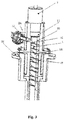
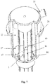
Fig. 1 is a structural schematic diagram of the spherical object falling buffer device according to an embodiment of the present application; -
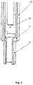
Fig. 2 is a structural schematic diagram of the flow-limiting pipe assembly in the spherical object falling buffer device according to an embodiment of the present application; -
Fig. 3 is a structural schematic diagram of the central column assembly in the spherical object falling buffer device according to an embodiment of the present application; -
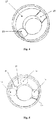
Fig. 4 is a diagram illustrating the redirecting joint in the spherical object falling buffer device according to an embodiment of the present application; -
Fig. 5 is a diagram illustrating a cooperation state of the redirecting joint in the spherical object falling buffer device and the spherical objects according to an embodiment of the present application; -
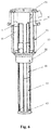
Fig. 6 is another structural schematic diagram of the central column assembly in the spherical object falling buffer device according to an embodiment of the present application; -
Fig. 7 is a structural schematic diagram of the connecting column and the connecting rod in the spherical object falling buffer device according to an embodiment of the present application; -
Fig. 8 is a structural schematic diagram of the sphere outlet rod in the spherical object falling buffer device according to an embodiment of the present application; and -
Fig. 9 is a top view of the redirecting joint in the spherical object falling buffer device according to an embodiment of the present application; - In the drawings:
1 spherical object 2 shielding assembly; 10 central column assembly 11 central column support 12 central column 13 flow-guiding region 14 outer cylindrical surface 15 spiral guide plate 16 space over redirecting joint 17 second convex rib 20 flow-limiting pipe assembly 21 flow-limiting pipe 22 redirecting join 23 sphere outlet pipe 24 sphere inlet hole 25 inner cylindrical surface of flow-limiting pipe 26 bearing 27 conical surface 28 concave groove 29 first convex rib 30 feed pipe assembly 31 feed pipe 32 feed pipe orifice 40 connecting column 41 connecting rod 42 sphere outlet rod 43 redirecting end 44 vertical guide groove 45 connecting end 46 straight edge section 47 guide groove edge 48 inner inclined surface 49 external tapered surface 50 sphere outlet pipe gap 51 sphere falling region - In order to make the objectives, technical solutions, and advantages of the embodiments of the present application clearer, the technical solutions of the embodiments of the present application will be clearly and completely described with reference to the accompanying drawings of the embodiments of the present application. Obviously, the described embodiments are part but not all of the embodiments of the present application. Based on the embodiments of the present application, all other embodiments obtained by a person of ordinary skill in the art without creative efforts shall fall within the protection scope of the present application.
- As shown in
Fig. 1 to Fig. 9 , the embodiments of the present application provide a spherical object falling buffer device, including acentral column assembly 10, a flow-limitingpipe assembly 20 and a sphereinlet pipe assembly 30. Thecentral column assembly 10 is arranged in the flow-limitingpipe assembly 20, and the sphereinlet pipe assembly 30 is connected with the flow-limitingpipe assembly 20. - The flow-limiting
pipe assembly 20 includes a flow-limitingpipe 21, a redirectingjoint 22 and asphere outlet pipe 23 that are connected in an order from top to bottom. A diameter of the flow-limitingpipe 21 is greater than that of the sphere outlet pipe, and an inner surface of the redirectingjoint 22 is aconical surface 27. - The
central column assembly 10 includes acentral column 12 arranged in the flow-limitingpipe 21. A flow-guidingregion 13 is provided between the flow-limitingpipe 21 and thecentral column 12, and several gravity flow guide grooves are provided on an outer peripheral surface of thecentral column 12. - The sphere
inlet pipe assembly 30 is connected to an upper portion of the flow-limitingpipe 21. The sphereinlet pipe assembly 30 includesseveral feed pipes 31, and sphere inlet holes 24 of which the number is equal to that of thefeed pipes 31 are provided on the flow-limitingpipe 21. The sphere inlet holes 24 are connected to the flow-guidingregion 13. Each of thefeed pipes 31 is connected to each of the sphere inlet holes 24 in a one-to-one correspondence respectively throughfeed pipe orifices 32. While a number of the provided sphere inlet hole 24 is equal to that of the gravity flow guide grooves, and each of the sphere inlet holes 24 is in a one-to-one correspondence to each of the gravity flow guide grooves respectively. - The
central column assembly 10 further includes acentral column support 11 connected with the top of thecentral column 12. Thecentral column support 11 is connected with the flow-limitingpipe 21, and a shielding assembly 2 is further provided at the top of the flow-limitingpipe 21. The shielding assembly 2 is configured to shield the core neutron, so as to compensate the shielding of the core fuel element neutron by the flow-guidingregion 13. Abearing 26 is further provided on the outside of the flow-limitingpipe 21. The spherical object falling buffer device of the present application is mounted at a center of a support plate of a metal member in the reactor through thesupport 26. - In an embodiment of the present application, after the
spherical object 1 is introduced into the flow-guidingregion 13 from thefeed pipe 31, it spirally falls along an inner wall of the flow-limitingpipe 21 under the action of motion inertia and gravity, then reaches theconical surface 27 of the redirectingjoint 22, and then continues rotating and finally falls into a stock bin from thesphere outlet pipe 23 under the action of friction and gravity. If the initial speed is too small, thespherical object 1 may fall quickly from the flow-guidingregion 13 to theconical surface 27 of the redirectingjoint 22, and part of its momentum is converted into impulse after being rebounded, and falls from thesphere outlet pipe 23 into the stock bin after its speed is slowed. - In a specific embodiment of the present application, the gravity flow guide grooves are spiral guide grooves annularly arranged on the outer peripheral surface of the central column. That is,
spiral guide plates 15 are arranged on an outer cylindrical surface 14 of thecentral column 12 so as to form the spiral guide grooves. - In the present embodiment, the sphere
inlet pipe assembly 30 is provided with twofeed pipes 31, therefore twospiral guide plates 15 are provided on thecentral column 12 correspondingly to the twofeed pipes 31. By the guidance of thespiral guide plates 15, thespherical object 1 spirally falls along an inner wall surface 25 of the flow-limitingpipe 21 or spirally falls along the spiral guide grooves on thecentral column 12 after it enters the flow-guidingregion 13 from the sphere inlet hole 24. Due to the support and friction effect of thespiral guide plates 15, the spiral falling speed of thespherical object 1 is reduced relative to a smooth pipe. After thespherical object 1 leaves thecentral column 12 and enters a space over redirecting joint 16, it is easier to fall onto theconical surface 27 of the redirecting joint 22 below, then thespherical object 1 falls via thesphere outlet pipe 23 after rotating, or falls via thesphere outlet pipe 23 after being rebounded, or directly falls through thesphere outlet pipe 23. - A first convex rib or a concave groove is provided on the inner surface of the redirecting joint.
- In a specific embodiment of the present application, when a plurality of sphere inlet holes 24 are provided on the flow-limiting
pipe 21, a distance between the bottom end of thecentral column 12 and theconical surface 27 of the redirecting joint 22 should be greater than two times the diameter of thespherical object 1, so as to avoid that after a plurality ofspherical objects 1 arrive at the space over redirecting joint 16 simultaneously, the movement between thespherical objects 1 affects each other, or a bridge is formed in the extreme case, and thespherical object 1 is rebounded from the redirecting joint 22 to hit thecentral column 12. - In a specific embodiment of the present application, in order to avoid that the
spherical objects 1 rotate on theconical surface 27 for a long time and do not fall, are over-rebounded or form a bridge, etc., a firstconvex rib 29 can be provided on theconical surface 27 of the redirecting joint 22, and aconcave groove 28 can also be provided on theconical surface 27 of the redirecting joint 22, or the firstconvex rib 29 and theconcave groove 28 can be provided on theconical surface 27 of the redirecting joint 22 at the same time. By providing the firstconvex rib 29 and/or theconcave groove 28, movement disturbance and buffering can be applied to thespherical objects 1. Compared with the spherical object 1a moving steadily on theconical surface 27, thespherical object 1b can sink into theconcave groove 28, or when thespherical object 1c moves up and fall on the firstconvex rib 29, both the movement track and the speed of the spherical object are abruptly changed due to interference or obstacles, resulting in imbalanced movement and quickly leaving theconical surface 27, and finally falling via thesphere outlet pipe 23. - In a specific embodiment of the present application, the bottom of the
central column 12 passes through the redirecting joint 22 and thesphere outlet pipe 23 in sequence. Thesphere outlet pipe 23 is disposed outside thecentral column 12. A sphereoutlet pipe gap 50 between thesphere outlet pipe 23 and the central column is insufficient to let thespherical object 1 pass through. At this time,vertical guide grooves 44 are used as the gravity flow guide grooves. That is, thecentral column 12 is provided with a plurality of guide groove edges 47 extending vertically. The plurality of guide groove edges 47 are annularly arranged on the outer peripheral surface of thecentral column 12, onevertical guide groove 44 is formed between two adjacent guide groove edges 47, and thespherical object 1 can finally fall through thevertical guide groove 44. - In a specific embodiment of the present application, second
convex ribs 17 of which the number is equal to that of the guide groove edges 47 are provided on theconical surface 27 of the redirecting joint 22, and each secondconvex rib 17 corresponds one-to-one to each guidegroove edge 47 respectively, so that onesphere falling region 51 is formed between two adjacent secondconvex ribs 17, and eachsphere falling region 51 corresponds one-to-one to eachvertical guide groove 44. Thespherical object 1 enters the flow-guidingregion 13 from thefeed pipe orifice 32, spirally falls along the flow-guidingregion 13, and then reaches theconical surface 27 of the redirecting joint 22 and continues to move. At this time, affected by the obstacle of the secondconvex rib 17, thespherical object 1 finally enters thevertical guide groove 44 from thesphere falling region 51, and continues to fall downward along thevertical guide groove 44. - In a specific embodiment of the present application, the
vertical guide groove 44 includes a semi-circular arc groove section that is slightly larger than thespherical object 1, and twostraight edge sections 46 correspondingly tangent to both sides of the semi-circular arc groove section, respectively. As long as thesphere outlet pipe 23 meets a certain length requirement, thespherical object 1 can be guided to fall in thevertical guide groove 44 due to the restriction of thesphere outlet pipe 23 and thevertical guide groove 44. - In a specific embodiment of the present application, the central column includes a connecting
column 40 and a connectingrod 41 that arranged in sequence from top to bottom. The connectingcolumn 40 is detachably connected to the connectingrod 41. In this embodiment, the connectingcolumn 40 is arranged in the flow-limitingpipe 21, and a bottom of the connectingrod 41 passes through the redirecting joint 22 and arranged in thesphere outlet pipe 23. According to the height requirement of the feed region, a plurality of sections of the connectingrod 41 may be provided, and then the plurality of sections of the connectingrod 41 are sequentially connected to the bottom of the connectingcolumn 40. - In a specific embodiment of the present application, when the distance from an exit of the redirecting joint 22 to an exit of the
vertical guide groove 44 on the central column is large, in order to limit the speed at which thespherical object 1 reaches the exit, thecentral column 12 includes a connectingcolumn 40, a connectingrod 41 and asphere outlet rod 42 that are connected in sequence from top to bottom. In this embodiment, a bottom of thesphere outlet rod 42 is provided with a redirectingend 43, and thesphere outlet rod 42 is detachably connected to the connectingrod 41 through a connecting end. The redirectingend 43 includes innerinclined surfaces 48 provided in the respectivevertical guide grooves 44 respectively and an external taperedsurface 49 provided on the outside of thesphere outlet rod 42. A smooth transition occurs between thevertical guide groove 44 and the external taperedsurface 49 through the innerinclined surface 48. When thespherical object 1 accelerates to fall along thevertical guide groove 44 and reaches the innerinclined surface 48, it collides with the innerinclined surface 48, and part of the momentum is converted into impulse to buffer and decelerate, and thespherical object 1 falls into the stock bin under the guide of the innerinclined surface 48 and the external taperedsurface 49. - In each of the embodiments above, spiral guide grooves are used as the gravity flow guide grooves, which are more suitable for cyclic loading and unloading where the material level is kept relatively constant, such as the core cyclic loading of a pebble bed reactor during normal operation. While the
vertical guide grooves 44 are used as the gravity flow guide grooves, and the central column is arranged to include the connectingcolumn 40, the connectingrod 41 and thesphere outlet rod 42 that are detachably connected in sequence, it is more suitable for continuous loading with varying material levels, such as the initial core loading of the pebble bed reactor. As the material level rises to a certain height, the connectingrod 41 orsphere outlet rod 42 can be disassembled to achieve telescopic loading. In the case that the strength and rigidity are sufficient, as long as the flow of the spherical objects in the stock bin is not adversely affected, the connectingrod 41 and thesphere outlet rod 42 may not be disassembled and may be the fixed central column assembly in the stock bin. As the material level ascends continuously, thesphere outlet rod 42 and the connectingrod 41 are successively buried. - In summary, in the spherical object falling buffer device according to the embodiments of the present application, a central column assembly is provided in the flow-limiting pipe assembly, so that a flow-guiding region is formed between the flow-limiting pipe and the central column. By arranging a plurality of gravity flow guide grooves on the outer peripheral surface of the central column, the spherical objects can only move in the flow-guiding regions between the flow-limiting pipes and the central column, and are restricted and guided by the gravity flow guide grooves during falling, and the spherical objects will be further buffered by the conical surface when they fall to the redirecting joint, so that the spherical objects will not directly fall into the stock bin from the center of the flow-limiting pipe regardless of the initial velocity of the spherical objects, thereby avoiding the collision damage of the spherical objects or the stock bin due to the excessive falling speed of the spherical objects. The spherical object falling buffer device has a good protective effect on the spherical objects and the stock bin entity, and has simple structure as well as convenient installation, which can meet the reliability requirement of buffer loading of the spherical objects under various working conditions.
- In the description of the present application, it should be noted that, the terms "connected with" and "connected to" should be understood in a broad sense unless otherwise specified and limited, for example, they may be fixed connections, detachable connections, or integrated connections; they can be mechanical connections or electrical connections; they can be direct connections or indirect connections through intermediate mediums. For those of ordinary skill in the art, the specific meanings of the above terms in this application can be understood according to specific situations.
- In the description of the present application, unless otherwise stated, "several" means one or more; "multiple" means two or more. The orientation or position relations indicated by the terms "upper", "lower", "left", "right", "inner", "outer" and etc. are based on the orientation or position relations shown in the drawings, and are only for the convenience of describing the present application and simplifying the description, rather than indicating or implying that the referred device or element must have a specific orientation, be constructed and operated in a specific orientation, and therefore cannot be understood as limiting the present application.
- Finally, it should be noted that the embodiments above are only used to illustrate rather than limit the technical solutions of the present application. Although the present application has been described in detail with reference to the foregoing embodiments, those of ordinary skill in the art should understand that they can still modify the technical solutions described in the various embodiments above, or equivalently replace some of the technical features thereof; and these modifications or replacements do not depart the essence of the corresponding solutions from the spirit and scope of the technical solutions of the various embodiments of the present application.
Claims (10)
- A spherical object falling buffer device, comprising a flow-limiting pipe assembly and a central column assembly; characterized in that the flow-limiting pipe assembly comprises a flow-limiting pipe, a redirecting joint and a sphere outlet pipe that are connected in sequence from top to bottom; a diameter of the flow-limiting pipe is greater than that of the sphere outlet pipe, and an inner surface of the redirecting joint is a conical surface; the central column assembly comprises at least a central column arranged in the flow-limiting pipe; a flow-guiding region is provided between the flow-limiting pipe and the central column, and several gravity flow guide grooves are provided on an outer peripheral surface of the central column.
- The spherical object falling buffer device of claim 1, characterized in that the gravity flow guide grooves are spiral guide grooves annularly arranged on the outer peripheral surface of the central column.
- The spherical object falling buffer device of claim 1, characterized in that the central column comprises a connecting column and a connecting rod that arranged in sequence from top to bottom; the connecting column is arranged in the flow-limiting pipe; a bottom of the connecting rod passes through the redirecting joint and is arranged in the sphere outlet pipe; the connecting column is detachably connected to the connecting rod.
- The spherical object falling buffer device of claim 3, characterized in that the central column further comprises a sphere outlet rod connected to the connecting rod, and a bottom of the sphere outlet rod is provided with a redirecting end.
- The spherical object falling buffer device of claim 4, characterized in that the gravity flow guide grooves are vertical guide grooves; the central column is provided with a plurality of guide groove edges extending vertically, the plurality of guide groove edges are annularly arranged on the outer peripheral surface of the central column, and one vertical guide groove is formed between two adjacent guide groove edges.
- The spherical object falling buffer device of claim 5, characterized in that the redirecting end comprises inner inclined surfaces provided in the respective vertical guide grooves respectively and an external tapered surface provided on the outside of the sphere outlet rod; the external tapered surface and the vertical guide groove are connected through the inner inclined surface in a smooth transition manner.
- The spherical object falling buffer device of claim 2, characterized in that a first convex rib or a concave groove is provided on the inner surface of the redirecting joint.
- The spherical object falling buffer device of claim 5, characterized in that second convex ribs of which the number is equal to that of the guide groove edges are provided on the inner surface of the redirecting joint, and each second convex rib corresponds one-to-one to each guide groove edge.
- The spherical object falling buffer device of claim 1, characterized in that it further comprises a sphere inlet pipe assembly connected to an upper portion of the flow-limiting pipe; wherein the sphere inlet pipe assembly comprises several feed pipes, and sphere inlet holes of which the number is equal to that of the feed pipes are provided on the flow-limiting pipe; the sphere inlet holes are connected to the flow-guiding region; and each of the feed pipes is connected to each of the sphere inlet holes in a one-to-one correspondence respectively through feed pipe orifices.
- The spherical object falling buffer device of claim 1, characterized in that the central column assembly further comprises a central column support connected to the top of the central column; wherein the central column support is connected to the flow-limiting pipe, and a shielding assembly is provided at the top of the flow-limiting pipe.
Applications Claiming Priority (2)
| Application Number | Priority Date | Filing Date | Title |
|---|---|---|---|
| CN201811639037.3A CN109607034B (en) | 2018-12-29 | 2018-12-29 | A ball drop buffer device |
| PCT/CN2019/121188 WO2020134808A1 (en) | 2018-12-29 | 2019-11-27 | Spherical object falling cushioning device |
Publications (4)
| Publication Number | Publication Date |
|---|---|
| EP3904240A1 true EP3904240A1 (en) | 2021-11-03 |
| EP3904240A4 EP3904240A4 (en) | 2022-08-31 |
| EP3904240B1 EP3904240B1 (en) | 2023-08-09 |
| EP3904240C0 EP3904240C0 (en) | 2023-08-09 |
Family
ID=66015763
Family Applications (1)
| Application Number | Title | Priority Date | Filing Date |
|---|---|---|---|
| EP19904789.5A Active EP3904240B1 (en) | 2018-12-29 | 2019-11-27 | Spherical object falling cushioning device |
Country Status (8)
| Country | Link |
|---|---|
| US (1) | US11661282B2 (en) |
| EP (1) | EP3904240B1 (en) |
| JP (1) | JP6945255B2 (en) |
| KR (1) | KR102334515B1 (en) |
| CN (1) | CN109607034B (en) |
| MY (1) | MY206484A (en) |
| RU (1) | RU2756876C1 (en) |
| WO (1) | WO2020134808A1 (en) |
Cited By (1)
| Publication number | Priority date | Publication date | Assignee | Title |
|---|---|---|---|---|
| CN115502175A (en) * | 2022-09-06 | 2022-12-23 | 镇康县振兴矿业开发有限责任公司 | Tailing falling device based on tailing conveying treatment and application thereof |
Families Citing this family (3)
| Publication number | Priority date | Publication date | Assignee | Title |
|---|---|---|---|---|
| CN109607034B (en) | 2018-12-29 | 2019-11-22 | 清华大学 | A ball drop buffer device |
| DE202022003350U1 (en) * | 2021-03-16 | 2026-02-20 | Interroll Holding Ag | Funding order |
| CN114147133B (en) * | 2021-09-13 | 2025-03-25 | 珠海格力精密模具有限公司 | Core blanking device |
Family Cites Families (18)
| Publication number | Priority date | Publication date | Assignee | Title |
|---|---|---|---|---|
| GB968759A (en) * | 1962-08-28 | 1964-09-02 | Atomic Energy Authority Uk | Nuclear reactor valve |
| US4079830A (en) | 1976-10-06 | 1978-03-21 | Lipe Rollway Corporation | Cylinder orienter |
| US4332120A (en) * | 1980-03-05 | 1982-06-01 | Westinghouse Electric Corp. | Nuclear fuel pellet loading apparatus |
| DE3404905A1 (en) * | 1984-02-11 | 1985-08-14 | Hochtemperatur-Reaktorbau GmbH, 4600 Dortmund | HIGH TEMPERATURE REACTOR MEDIUM PERFORMANCE |
| US5048666A (en) * | 1989-03-02 | 1991-09-17 | Westinghouse Electric Corp. | Nuclear fuel pellet transfer escalator |
| DE19941991A1 (en) * | 1999-09-02 | 2001-03-08 | Bbc Reaktor Gmbh | Loading unit for pebble bed reactor spherical fuel, comprises pipe with impact members below the mouth, which slow spherical elements down |
| NO317083B1 (en) * | 2002-09-27 | 2004-08-02 | Catalyst Services Inc | Method of loading particulate matter into vertical rudders |
| FR2874212B1 (en) | 2004-08-13 | 2008-02-01 | Total France Sa | DEVICE FOR LOADING AN ENCLOSURE WITH SOLID PARTICLES AND METHOD USING THE DEVICE |
| CN101777397B (en) * | 2010-01-11 | 2012-05-16 | 清华大学 | High temperature gas-cooled reactor core scoring device |
| CN101853708B (en) * | 2010-02-08 | 2013-03-20 | 清华大学 | Spherical material buffer conveyor device |
| CN101794632B (en) * | 2010-03-02 | 2012-02-08 | 清华大学 | Ball bed high-temperature stack buffer device |
| SI2479727T1 (en) * | 2011-01-21 | 2016-01-29 | Novomatic Ag | Ball drawing machine with ball guide |
| CN204096442U (en) | 2014-09-25 | 2015-01-14 | 无锡明珠钢球有限公司 | A kind of steel ball blanking device |
| EP3015163B1 (en) | 2014-10-31 | 2020-09-30 | Petroval | Process for loading ceramic particles into a vertical reactor |
| CN105905517A (en) | 2016-05-28 | 2016-08-31 | 中煤张家口煤矿机械有限责任公司 | Falling material buffering chute |
| CN206351943U (en) | 2016-12-28 | 2017-07-25 | 襄阳市铁瑞电力科技有限公司 | A kind of ribbon conveyer transfers the high efficiency buffer cylinder between material |
| CN108695004B (en) | 2018-05-18 | 2019-04-09 | 西安交通大学 | Hydraulic buffer structure for hydraulic suspension passive shutdown experimental device |
| CN109607034B (en) | 2018-12-29 | 2019-11-22 | 清华大学 | A ball drop buffer device |
-
2018
- 2018-12-29 CN CN201811639037.3A patent/CN109607034B/en active Active
-
2019
- 2019-11-27 MY MYPI2020006836A patent/MY206484A/en unknown
- 2019-11-27 EP EP19904789.5A patent/EP3904240B1/en active Active
- 2019-11-27 US US17/254,203 patent/US11661282B2/en active Active
- 2019-11-27 RU RU2021101624A patent/RU2756876C1/en active
- 2019-11-27 KR KR1020207015944A patent/KR102334515B1/en active Active
- 2019-11-27 JP JP2020552301A patent/JP6945255B2/en active Active
- 2019-11-27 WO PCT/CN2019/121188 patent/WO2020134808A1/en not_active Ceased
Cited By (1)
| Publication number | Priority date | Publication date | Assignee | Title |
|---|---|---|---|---|
| CN115502175A (en) * | 2022-09-06 | 2022-12-23 | 镇康县振兴矿业开发有限责任公司 | Tailing falling device based on tailing conveying treatment and application thereof |
Also Published As
| Publication number | Publication date |
|---|---|
| WO2020134808A1 (en) | 2020-07-02 |
| RU2756876C1 (en) | 2021-10-06 |
| EP3904240A4 (en) | 2022-08-31 |
| KR102334515B1 (en) | 2021-12-02 |
| EP3904240B1 (en) | 2023-08-09 |
| EP3904240C0 (en) | 2023-08-09 |
| MY206484A (en) | 2024-12-18 |
| CN109607034A (en) | 2019-04-12 |
| US11661282B2 (en) | 2023-05-30 |
| KR20200083569A (en) | 2020-07-08 |
| JP6945255B2 (en) | 2021-10-06 |
| JP2021521414A (en) | 2021-08-26 |
| CN109607034B (en) | 2019-11-22 |
| US20210261341A1 (en) | 2021-08-26 |
Similar Documents
| Publication | Publication Date | Title |
|---|---|---|
| EP3904240B1 (en) | Spherical object falling cushioning device | |
| RU2448916C2 (en) | Methods of producing optical fibers | |
| KR910001639B1 (en) | Device for guiding a control cluster in a nuclear reactor | |
| CN109607240B (en) | Discharging device | |
| EP4583120A1 (en) | Reactor vortex suppression and flow distribution device | |
| TWM593484U (en) | Ball screw assembly | |
| EP0157585A2 (en) | Stack system | |
| CN215253620U (en) | Three-dimensional shock isolation device | |
| US4624826A (en) | Control rod velocity limiter | |
| JP2017049170A (en) | Atomic reactor | |
| JP2014122856A (en) | Nuclear reactor structure of pressurized water reactor | |
| US11557402B2 (en) | Nuclear reactor, guide tube support, and corresponding maintenance method | |
| SE470292B (en) | Fuel elements for a light water nuclear reactor | |
| CN210237777U (en) | Multi-beam laser center powder feeding cladding head and laser cladding processing system | |
| CN109301440B (en) | A cable-based posture adjustment and control system | |
| CN207421127U (en) | A kind of line slideway | |
| US5513233A (en) | Nuclear reactor | |
| US20170337993A1 (en) | Fuel Assembly | |
| CN223291744U (en) | A cone-type deflector for protecting coal bunker | |
| CN216697588U (en) | Low-gravity simulation test platform for extraterrestrial celestial body | |
| CN223408654U (en) | A spiral vertical transfer device | |
| JPH09127282A (en) | Fast reactor core and its special assembly | |
| US6151376A (en) | Nuclear fuel assembly | |
| EP0640988A1 (en) | Transition piece for reducing coolant pressure drop for bottom entry nuclear fuel assemblies | |
| US6396893B1 (en) | Apparatus and method for adjusting the weight of a velocity limiter for a control rod of a nuclear reactor |
Legal Events
| Date | Code | Title | Description |
|---|---|---|---|
| STAA | Information on the status of an ep patent application or granted ep patent |
Free format text: STATUS: THE INTERNATIONAL PUBLICATION HAS BEEN MADE |
|
| PUAI | Public reference made under article 153(3) epc to a published international application that has entered the european phase |
Free format text: ORIGINAL CODE: 0009012 |
|
| STAA | Information on the status of an ep patent application or granted ep patent |
Free format text: STATUS: REQUEST FOR EXAMINATION WAS MADE |
|
| 17P | Request for examination filed |
Effective date: 20210113 |
|
| AK | Designated contracting states |
Kind code of ref document: A1 Designated state(s): AL AT BE BG CH CY CZ DE DK EE ES FI FR GB GR HR HU IE IS IT LI LT LU LV MC MK MT NL NO PL PT RO RS SE SI SK SM TR |
|
| DAV | Request for validation of the european patent (deleted) | ||
| DAX | Request for extension of the european patent (deleted) | ||
| REG | Reference to a national code |
Ref country code: DE Ref legal event code: R079 Free format text: PREVIOUS MAIN CLASS: B65G0011200000 Ipc: G21C0019200000 Ref country code: DE Ref legal event code: R079 Ref document number: 602019034878 Country of ref document: DE Free format text: PREVIOUS MAIN CLASS: B65G0011200000 Ipc: G21C0019200000 |
|
| A4 | Supplementary search report drawn up and despatched |
Effective date: 20220803 |
|
| RIC1 | Information provided on ipc code assigned before grant |
Ipc: G21C 5/02 20060101ALI20220728BHEP Ipc: G21C 1/07 20060101ALI20220728BHEP Ipc: G21C 19/20 20060101AFI20220728BHEP |
|
| GRAP | Despatch of communication of intention to grant a patent |
Free format text: ORIGINAL CODE: EPIDOSNIGR1 |
|
| STAA | Information on the status of an ep patent application or granted ep patent |
Free format text: STATUS: GRANT OF PATENT IS INTENDED |
|
| INTG | Intention to grant announced |
Effective date: 20230323 |
|
| GRAS | Grant fee paid |
Free format text: ORIGINAL CODE: EPIDOSNIGR3 |
|
| GRAA | (expected) grant |
Free format text: ORIGINAL CODE: 0009210 |
|
| STAA | Information on the status of an ep patent application or granted ep patent |
Free format text: STATUS: THE PATENT HAS BEEN GRANTED |
|
| AK | Designated contracting states |
Kind code of ref document: B1 Designated state(s): AL AT BE BG CH CY CZ DE DK EE ES FI FR GB GR HR HU IE IS IT LI LT LU LV MC MK MT NL NO PL PT RO RS SE SI SK SM TR |
|
| REG | Reference to a national code |
Ref country code: GB Ref legal event code: FG4D |
|
| REG | Reference to a national code |
Ref country code: CH Ref legal event code: EP |
|
| REG | Reference to a national code |
Ref country code: DE Ref legal event code: R096 Ref document number: 602019034878 Country of ref document: DE |
|
| REG | Reference to a national code |
Ref country code: IE Ref legal event code: FG4D |
|
| U01 | Request for unitary effect filed |
Effective date: 20230809 |
|
| U07 | Unitary effect registered |
Designated state(s): AT BE BG DE DK EE FI FR IT LT LU LV MT NL PT SE SI Effective date: 20230814 |
|
| U20 | Renewal fee for the european patent with unitary effect paid |
Year of fee payment: 5 Effective date: 20231123 |
|
| PG25 | Lapsed in a contracting state [announced via postgrant information from national office to epo] |
Ref country code: GR Free format text: LAPSE BECAUSE OF FAILURE TO SUBMIT A TRANSLATION OF THE DESCRIPTION OR TO PAY THE FEE WITHIN THE PRESCRIBED TIME-LIMIT Effective date: 20231110 |
|
| PG25 | Lapsed in a contracting state [announced via postgrant information from national office to epo] |
Ref country code: IS Free format text: LAPSE BECAUSE OF FAILURE TO SUBMIT A TRANSLATION OF THE DESCRIPTION OR TO PAY THE FEE WITHIN THE PRESCRIBED TIME-LIMIT Effective date: 20231209 |
|
| PG25 | Lapsed in a contracting state [announced via postgrant information from national office to epo] |
Ref country code: RS Free format text: LAPSE BECAUSE OF FAILURE TO SUBMIT A TRANSLATION OF THE DESCRIPTION OR TO PAY THE FEE WITHIN THE PRESCRIBED TIME-LIMIT Effective date: 20230809 Ref country code: NO Free format text: LAPSE BECAUSE OF FAILURE TO SUBMIT A TRANSLATION OF THE DESCRIPTION OR TO PAY THE FEE WITHIN THE PRESCRIBED TIME-LIMIT Effective date: 20231109 Ref country code: IS Free format text: LAPSE BECAUSE OF FAILURE TO SUBMIT A TRANSLATION OF THE DESCRIPTION OR TO PAY THE FEE WITHIN THE PRESCRIBED TIME-LIMIT Effective date: 20231209 Ref country code: HR Free format text: LAPSE BECAUSE OF FAILURE TO SUBMIT A TRANSLATION OF THE DESCRIPTION OR TO PAY THE FEE WITHIN THE PRESCRIBED TIME-LIMIT Effective date: 20230809 Ref country code: GR Free format text: LAPSE BECAUSE OF FAILURE TO SUBMIT A TRANSLATION OF THE DESCRIPTION OR TO PAY THE FEE WITHIN THE PRESCRIBED TIME-LIMIT Effective date: 20231110 |
|
| PG25 | Lapsed in a contracting state [announced via postgrant information from national office to epo] |
Ref country code: PL Free format text: LAPSE BECAUSE OF FAILURE TO SUBMIT A TRANSLATION OF THE DESCRIPTION OR TO PAY THE FEE WITHIN THE PRESCRIBED TIME-LIMIT Effective date: 20230809 |
|
| PG25 | Lapsed in a contracting state [announced via postgrant information from national office to epo] |
Ref country code: ES Free format text: LAPSE BECAUSE OF FAILURE TO SUBMIT A TRANSLATION OF THE DESCRIPTION OR TO PAY THE FEE WITHIN THE PRESCRIBED TIME-LIMIT Effective date: 20230809 |
|
| PG25 | Lapsed in a contracting state [announced via postgrant information from national office to epo] |
Ref country code: SM Free format text: LAPSE BECAUSE OF FAILURE TO SUBMIT A TRANSLATION OF THE DESCRIPTION OR TO PAY THE FEE WITHIN THE PRESCRIBED TIME-LIMIT Effective date: 20230809 Ref country code: RO Free format text: LAPSE BECAUSE OF FAILURE TO SUBMIT A TRANSLATION OF THE DESCRIPTION OR TO PAY THE FEE WITHIN THE PRESCRIBED TIME-LIMIT Effective date: 20230809 Ref country code: ES Free format text: LAPSE BECAUSE OF FAILURE TO SUBMIT A TRANSLATION OF THE DESCRIPTION OR TO PAY THE FEE WITHIN THE PRESCRIBED TIME-LIMIT Effective date: 20230809 Ref country code: CZ Free format text: LAPSE BECAUSE OF FAILURE TO SUBMIT A TRANSLATION OF THE DESCRIPTION OR TO PAY THE FEE WITHIN THE PRESCRIBED TIME-LIMIT Effective date: 20230809 Ref country code: SK Free format text: LAPSE BECAUSE OF FAILURE TO SUBMIT A TRANSLATION OF THE DESCRIPTION OR TO PAY THE FEE WITHIN THE PRESCRIBED TIME-LIMIT Effective date: 20230809 |
|
| REG | Reference to a national code |
Ref country code: DE Ref legal event code: R097 Ref document number: 602019034878 Country of ref document: DE |
|
| PLBE | No opposition filed within time limit |
Free format text: ORIGINAL CODE: 0009261 |
|
| STAA | Information on the status of an ep patent application or granted ep patent |
Free format text: STATUS: NO OPPOSITION FILED WITHIN TIME LIMIT |
|
| REG | Reference to a national code |
Ref country code: CH Ref legal event code: PL |
|
| PG25 | Lapsed in a contracting state [announced via postgrant information from national office to epo] |
Ref country code: MC Free format text: LAPSE BECAUSE OF FAILURE TO SUBMIT A TRANSLATION OF THE DESCRIPTION OR TO PAY THE FEE WITHIN THE PRESCRIBED TIME-LIMIT Effective date: 20230809 |
|
| 26N | No opposition filed |
Effective date: 20240513 |
|
| PG25 | Lapsed in a contracting state [announced via postgrant information from national office to epo] |
Ref country code: CH Free format text: LAPSE BECAUSE OF NON-PAYMENT OF DUE FEES Effective date: 20231130 |
|
| GBPC | Gb: european patent ceased through non-payment of renewal fee |
Effective date: 20231127 |
|
| PG25 | Lapsed in a contracting state [announced via postgrant information from national office to epo] |
Ref country code: MC Free format text: LAPSE BECAUSE OF FAILURE TO SUBMIT A TRANSLATION OF THE DESCRIPTION OR TO PAY THE FEE WITHIN THE PRESCRIBED TIME-LIMIT Effective date: 20230809 Ref country code: CH Free format text: LAPSE BECAUSE OF NON-PAYMENT OF DUE FEES Effective date: 20231130 |
|
| REG | Reference to a national code |
Ref country code: IE Ref legal event code: MM4A |
|
| PG25 | Lapsed in a contracting state [announced via postgrant information from national office to epo] |
Ref country code: IE Free format text: LAPSE BECAUSE OF NON-PAYMENT OF DUE FEES Effective date: 20231127 |
|
| PG25 | Lapsed in a contracting state [announced via postgrant information from national office to epo] |
Ref country code: GB Free format text: LAPSE BECAUSE OF NON-PAYMENT OF DUE FEES Effective date: 20231127 |
|
| PG25 | Lapsed in a contracting state [announced via postgrant information from national office to epo] |
Ref country code: IE Free format text: LAPSE BECAUSE OF NON-PAYMENT OF DUE FEES Effective date: 20231127 Ref country code: GB Free format text: LAPSE BECAUSE OF NON-PAYMENT OF DUE FEES Effective date: 20231127 |
|
| U20 | Renewal fee for the european patent with unitary effect paid |
Year of fee payment: 6 Effective date: 20241126 |
|
| PG25 | Lapsed in a contracting state [announced via postgrant information from national office to epo] |
Ref country code: CY Free format text: LAPSE BECAUSE OF FAILURE TO SUBMIT A TRANSLATION OF THE DESCRIPTION OR TO PAY THE FEE WITHIN THE PRESCRIBED TIME-LIMIT; INVALID AB INITIO Effective date: 20191127 |
|
| PG25 | Lapsed in a contracting state [announced via postgrant information from national office to epo] |
Ref country code: HU Free format text: LAPSE BECAUSE OF FAILURE TO SUBMIT A TRANSLATION OF THE DESCRIPTION OR TO PAY THE FEE WITHIN THE PRESCRIBED TIME-LIMIT; INVALID AB INITIO Effective date: 20191127 |
|
| PG25 | Lapsed in a contracting state [announced via postgrant information from national office to epo] |
Ref country code: TR Free format text: LAPSE BECAUSE OF FAILURE TO SUBMIT A TRANSLATION OF THE DESCRIPTION OR TO PAY THE FEE WITHIN THE PRESCRIBED TIME-LIMIT Effective date: 20230809 |
|
| U20 | Renewal fee for the european patent with unitary effect paid |
Year of fee payment: 7 Effective date: 20251127 |