EP3904234A1 - Carrier for containers - Google Patents
Carrier for containers Download PDFInfo
- Publication number
- EP3904234A1 EP3904234A1 EP20215371.4A EP20215371A EP3904234A1 EP 3904234 A1 EP3904234 A1 EP 3904234A1 EP 20215371 A EP20215371 A EP 20215371A EP 3904234 A1 EP3904234 A1 EP 3904234A1
- Authority
- EP
- European Patent Office
- Prior art keywords
- panel
- openings
- central panel
- containers
- carrier
- Prior art date
- Legal status (The legal status is an assumption and is not a legal conclusion. Google has not performed a legal analysis and makes no representation as to the accuracy of the status listed.)
- Granted
Links
Images







Classifications
-
- B—PERFORMING OPERATIONS; TRANSPORTING
- B65—CONVEYING; PACKING; STORING; HANDLING THIN OR FILAMENTARY MATERIAL
- B65D—CONTAINERS FOR STORAGE OR TRANSPORT OF ARTICLES OR MATERIALS, e.g. BAGS, BARRELS, BOTTLES, BOXES, CANS, CARTONS, CRATES, DRUMS, JARS, TANKS, HOPPERS, FORWARDING CONTAINERS; ACCESSORIES, CLOSURES, OR FITTINGS THEREFOR; PACKAGING ELEMENTS; PACKAGES
- B65D71/00—Bundles of articles held together by packaging elements for convenience of storage or transport, e.g. portable segregating carrier for plural receptacles such as beer cans or pop bottles; Bales of material
- B65D71/0085—Packaging elements adhered to the articles, e.g. a carton sheet
-
- B—PERFORMING OPERATIONS; TRANSPORTING
- B65—CONVEYING; PACKING; STORING; HANDLING THIN OR FILAMENTARY MATERIAL
- B65D—CONTAINERS FOR STORAGE OR TRANSPORT OF ARTICLES OR MATERIALS, e.g. BAGS, BARRELS, BOTTLES, BOXES, CANS, CARTONS, CRATES, DRUMS, JARS, TANKS, HOPPERS, FORWARDING CONTAINERS; ACCESSORIES, CLOSURES, OR FITTINGS THEREFOR; PACKAGING ELEMENTS; PACKAGES
- B65D71/00—Bundles of articles held together by packaging elements for convenience of storage or transport, e.g. portable segregating carrier for plural receptacles such as beer cans or pop bottles; Bales of material
- B65D71/40—Bundles of articles held together by packaging elements for convenience of storage or transport, e.g. portable segregating carrier for plural receptacles such as beer cans or pop bottles; Bales of material comprising a plurality of articles held together only partially by packaging elements formed by folding a blank or several blanks
- B65D71/42—Bundles of articles held together by packaging elements for convenience of storage or transport, e.g. portable segregating carrier for plural receptacles such as beer cans or pop bottles; Bales of material comprising a plurality of articles held together only partially by packaging elements formed by folding a blank or several blanks formed by folding a single blank into a single layer element
-
- B—PERFORMING OPERATIONS; TRANSPORTING
- B65—CONVEYING; PACKING; STORING; HANDLING THIN OR FILAMENTARY MATERIAL
- B65D—CONTAINERS FOR STORAGE OR TRANSPORT OF ARTICLES OR MATERIALS, e.g. BAGS, BARRELS, BOTTLES, BOXES, CANS, CARTONS, CRATES, DRUMS, JARS, TANKS, HOPPERS, FORWARDING CONTAINERS; ACCESSORIES, CLOSURES, OR FITTINGS THEREFOR; PACKAGING ELEMENTS; PACKAGES
- B65D2571/00—Bundles of articles held together by packaging elements for convenience of storage or transport, e.g. portable segregating carrier for plural receptacles such as beer cans, pop bottles; Bales of material
- B65D2571/00123—Bundling wrappers or trays
- B65D2571/00129—Wrapper locking means
- B65D2571/00135—Wrapper locking means integral with the wrapper
- B65D2571/00141—Wrapper locking means integral with the wrapper glued
-
- B—PERFORMING OPERATIONS; TRANSPORTING
- B65—CONVEYING; PACKING; STORING; HANDLING THIN OR FILAMENTARY MATERIAL
- B65D—CONTAINERS FOR STORAGE OR TRANSPORT OF ARTICLES OR MATERIALS, e.g. BAGS, BARRELS, BOTTLES, BOXES, CANS, CARTONS, CRATES, DRUMS, JARS, TANKS, HOPPERS, FORWARDING CONTAINERS; ACCESSORIES, CLOSURES, OR FITTINGS THEREFOR; PACKAGING ELEMENTS; PACKAGES
- B65D2571/00—Bundles of articles held together by packaging elements for convenience of storage or transport, e.g. portable segregating carrier for plural receptacles such as beer cans, pop bottles; Bales of material
- B65D2571/00123—Bundling wrappers or trays
- B65D2571/00246—Locating elements for the contents
- B65D2571/00253—Locating elements for the contents integral with the wrapper
- B65D2571/00277—Slits or openings formed along a fold line
-
- B—PERFORMING OPERATIONS; TRANSPORTING
- B65—CONVEYING; PACKING; STORING; HANDLING THIN OR FILAMENTARY MATERIAL
- B65D—CONTAINERS FOR STORAGE OR TRANSPORT OF ARTICLES OR MATERIALS, e.g. BAGS, BARRELS, BOTTLES, BOXES, CANS, CARTONS, CRATES, DRUMS, JARS, TANKS, HOPPERS, FORWARDING CONTAINERS; ACCESSORIES, CLOSURES, OR FITTINGS THEREFOR; PACKAGING ELEMENTS; PACKAGES
- B65D2571/00—Bundles of articles held together by packaging elements for convenience of storage or transport, e.g. portable segregating carrier for plural receptacles such as beer cans, pop bottles; Bales of material
- B65D2571/00123—Bundling wrappers or trays
- B65D2571/00246—Locating elements for the contents
- B65D2571/00253—Locating elements for the contents integral with the wrapper
- B65D2571/00308—Locating elements for the contents integral with the wrapper consisting of inwardly bent panels or flaps
- B65D2571/00314—Locating elements for the contents integral with the wrapper consisting of inwardly bent panels or flaps with locating holes or cuts
-
- B—PERFORMING OPERATIONS; TRANSPORTING
- B65—CONVEYING; PACKING; STORING; HANDLING THIN OR FILAMENTARY MATERIAL
- B65D—CONTAINERS FOR STORAGE OR TRANSPORT OF ARTICLES OR MATERIALS, e.g. BAGS, BARRELS, BOTTLES, BOXES, CANS, CARTONS, CRATES, DRUMS, JARS, TANKS, HOPPERS, FORWARDING CONTAINERS; ACCESSORIES, CLOSURES, OR FITTINGS THEREFOR; PACKAGING ELEMENTS; PACKAGES
- B65D2571/00—Bundles of articles held together by packaging elements for convenience of storage or transport, e.g. portable segregating carrier for plural receptacles such as beer cans, pop bottles; Bales of material
- B65D2571/00123—Bundling wrappers or trays
- B65D2571/00648—Elements used to form the wrapper
- B65D2571/00654—Blanks
- B65D2571/0066—Blanks formed from one single sheet
-
- B—PERFORMING OPERATIONS; TRANSPORTING
- B65—CONVEYING; PACKING; STORING; HANDLING THIN OR FILAMENTARY MATERIAL
- B65D—CONTAINERS FOR STORAGE OR TRANSPORT OF ARTICLES OR MATERIALS, e.g. BAGS, BARRELS, BOTTLES, BOXES, CANS, CARTONS, CRATES, DRUMS, JARS, TANKS, HOPPERS, FORWARDING CONTAINERS; ACCESSORIES, CLOSURES, OR FITTINGS THEREFOR; PACKAGING ELEMENTS; PACKAGES
- B65D2571/00—Bundles of articles held together by packaging elements for convenience of storage or transport, e.g. portable segregating carrier for plural receptacles such as beer cans, pop bottles; Bales of material
- B65D2571/00123—Bundling wrappers or trays
- B65D2571/00833—Other details of wrappers
- B65D2571/00932—Flattenable or foldable packages
Definitions
- the present disclosure generally relates to cartons or carriers for holding, displaying, and/or transporting containers.
- the disclosure is generally directed to a carrier for holding a plurality of containers, the carrier comprising a plurality of panels comprising at least one central panel, at least one attachment panel foldably connected to the at least one central panel and configured to receive a portion of at least one container of the plurality of containers, and at least one side panel foldably connected to the at least one attachment panel.
- the at least one central panel comprises a plurality of openings and is positioned between and attached to adjacent containers of the plurality of containers, and the at least one side panel is attached to at least one container of the plurality of containers.
- the disclosure is generally directed to a blank for forming a carrier for holding a plurality of containers, the blank comprising a plurality of panels comprising at least one central panel, at least one attachment panel foldably connected to the at least one central panel and configured to receive a portion of at least one container of the plurality of containers, and at least one side panel foldably connected to the at least one attachment panel.
- the at least one central panel comprises a plurality of openings and is for being positioned between and attached to adjacent containers of the plurality of containers when the container is formed from the blank, and the at least one side panel is for being attached to at least one container of the plurality of containers when the container is formed from the blank.
- the disclosure is generally directed to a method of forming a carrier for holding a plurality of containers, the method comprising obtaining a blank comprising a plurality of panels comprising at least one central panel comprising a plurality of openings, at least one attachment panel foldably connected to the at least one central panel and configured to receive a portion of at least one container of the plurality of containers, and at least one side panel foldably connected to the at least one attachment panel.
- the method further comprises folding the plurality of panels such that the at least one central panel is positioned between adjacent containers of the plurality of containers, attaching the at least one central panel to the adjacent containers of the plurality of containers, attaching the at least one attachment panel to at least one container of the plurality of containers, and attaching the at least one side panel to at least one container of the plurality of containers.
- the disclosure is generally directed to a package comprising a plurality of containers and a carrier holding the plurality of containers.
- the carrier comprises a plurality of panels comprising at least one central panel, at least one attachment panel foldably connected to the at least one central panel and receiving a portion of at least one container of the plurality of containers, and at least one side panel foldably connected to the at least one attachment panel.
- the at least one central panel comprises a plurality of openings and is positioned between and attached to adjacent containers of the plurality of containers, and the at least one side panel is attached to at least one container of the plurality of containers.
- the present disclosure generally relates to carriers, packages, constructs, sleeves, cartons, or the like, for holding and displaying containers such as jars, bottles, cans, etc.
- the containers can be used for packaging food and beverage products, for example.
- the containers can be made from materials suitable in composition for packaging the particular food or beverage item, and the materials include, but are not limited to, glass; plastics such as PET, LDPE, LLDPE, HDPE, PP, PS, PVC, EVOH, and Nylon; and the like; aluminum and/or other metals; or any combination thereof.
- Carriers according to the present disclosure can accommodate containers of numerous different shapes.
- beverage containers e.g., aluminum cans
- the terms “lower,” “bottom,” “upper,” “top,” “front,” and “back” indicate orientations determined in relation to fully erected carriers.
- carriers may be formed by multiple overlapping panels, end flaps, and/or other portions of blanks.
- Such panels, end flaps, and/or other portions of the blank can be designated in relative terms to one another, e.g., "first”, “second”, “third”, etc., in sequential or non-sequential reference, without departing from the disclosure.
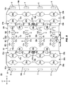
- Fig. 1 shows a schematic plan view of an exterior side 101 of a blank 103 used to form a carrier 105 ( Fig. 6 ) in accordance with a first exemplary embodiment of the disclosure.
- the carrier 105 is sized to contain or support eight containers, with four containers CA1, CA2, CA3, CA4 being attached to a front portion 106 of the carrier 105 and four containers CB1, CB2, CB3, CB4 being attached to a back portion 108 of the carrier 105.
- the containers CA1, CA2, CA3, CA4, CB1, CB2, CB3, CB4 can be beverage cans, or could be any other suitable type and size of container without departing from the disclosure.
- the carrier 105 can be sized and shaped to hold more or less than eight containers.
- the front portion 106 and the back portion 108 of the carrier 105 each have four containers, and in other embodiments, the front portion 106 and the back portion 108 of the carrier 105 can carry more or less than four containers without departing from the disclosure.
- the carrier 105 can be provided together with one or more containers as a package 110 ( Fig. 6 ).
- the blank 103 has a longitudinal axis L1 and a lateral axis L2.
- the blank 103 has a front portion 107 for forming the front portion 106 of the carrier 105, and a back portion 109 for forming the back portion 108 of the carrier 105.
- the front portion 107 and the back portion 109 of the blank 103 are foldably connected at a lateral fold line 112 that forms a lateral centerline CL of the blank 103, as shown.
- the blank 103 is at least partially formed into the carrier 105 by folding the blank 103 at the fold line 112 along the centerline CL so that the front portion 107 and the back portion 109 of the blank 103 are overlapped in at least partial face-to-face contact.
- the front portion 107 of the blank 103 comprises a front central panel 125a having a first front row RF1 of laterally spaced adhesive or glue openings 127a, and a second front row RF2 of the laterally spaced adhesive or glue openings 127a.
- the top edges of the respective glue openings 127a of the first row RF1 are spaced a longitudinal distance D1 apart from the fold line 112 that is less than a longitudinal distance D2 that the top edges of the respective glue openings 127a of the second row RF2 are spaced apart from the fold line 112.
- a front container retention panel or front attachment panel 131a is foldably connected to the front central panel 125a at a lateral fold line 133a, and includes a container retention portion 135a that is at least partially defined between a pair of longitudinally-spaced lateral fold lines 137a, 139a that are each interrupted by respective laterally-spaced cuts container openings 141a.
- the attachment panel 131a can include container retention features that include at least laterally-spaced container openings 141a are defined in respective cuts in the blank 103 that define a pair of laterally spaced curved edge portions 142a that intersect respective longitudinally spaced curved edge portions 143a to form the respective container openings 141a.
- the edge portions 142a of the blank 103 around the container openings 141a can have a generally U-shaped or generally V-shaped configuration so as to define a pair of lateral container retention tabs 148a that protrude/extend into the respective laterally-spaced container openings 141a.
- respective oblique cuts 144a, 145a extend outwardly from each respective curved edge portion 143a to define a plurality of reconfigurable edges of the front attachment panel 131a adjacent the respective container openings 141a.
- an interior marginal portion 136a of the attachment panel 131a is defined between the fold lines 137a, 133a, and an exterior marginal portion 138a of the attachment panel 131a is defined between the fold line 139a and a lateral fold line 140a.
- a bevel or front side panel 151a is foldably connected to the front attachment panel 131a at the lateral fold line 140a, and defines a lateral free edge of the blank 103.
- the blank 103 can include handle features that include at least a pair of handle openings 130a that interrupts the fold line 133a and that extends from a portion of the front central panel 125a into a portion of the front attachment panel 131a.
- the handle openings 130a can be formed by one or more cuts that include one or more curved and/or angled portions.
- a handle reinforcement tab 161a as shown, can be foldably connected to the front attachment panel 131a at respective longitudinal fold lines 163a and can be positioned to extend into the respective handle openings 130a.
- the handle features can include a handle opening 132a that can be positioned between the handle openings 130a, and that is formed in the front central panel 125a by one or more cuts that include one or more curved and/or angled portions.
- a pair of handle reinforcement tabs 165a can also be at least partially formed by respective curved cuts 167a and separated from one another at a longitudinal cut.
- the handle reinforcement tabs 165a as shown, can be foldably connected to the front attachment panel 131a at respective longitudinal fold lines 169a and can be positioned abutting the handle opening 132a.
- the carrier 105 can have a different arrangement of handle features, or can be devoid of handle features, without departing from the disclosure.
- the back portion 109 of the blank 103 includes a back central panel 125b, a back container retention panel or back attachment panel 131b, and a back bevel panel or back side panel 151b having associated features that are generally a mirror-image of the corresponding panels and flaps of the front portion 107 of the blank 103.
- Corresponding components e.g., panels, flaps, fold lines, cuts, etc.
- corresponding reference numbers that differ by the "a” or "b” suffix, with the "a” components corresponding to the front portion 107 of the blank 103 and the "b” components corresponding to the back portion 109 of the blank 103.
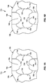
- the features of the back attachment panel 131a are best shown in Fig. 1B .
- the back central panel 125a includes a first back lateral row of glue openings 128 that at least partially interrupt the fold line 112 and have an upper edge spaced a longitudinal distance D3 from the fold line 112.
- the back central panel 125b also includes a second back lateral row RB2 of glue openings 127b with an upper edge spaced apart a longitudinal distance D4 from the fold line 112, the longitudinal distance D4 being greater than the longitudinal distance D3.
- the glue openings 127a, 127b can have a generally circular profile and the glue openings 128 can have a generally semicircular/semi-ovoid configuration. It will be understood that one or more of the glue openings 127a, 127b, 128 can have a different configuration than provided in Fig. 1 , e.g., generally circular, generally oblong, generally semicircular/semi-ovoid, generally rectangular, etc., without departing from the disclosure.
- the blank 103 is provided with front rows RF1 and RF2 of respective laterally-spaced front glue openings 127a that are spaced respective longitudinal distances D1, D2 from the centerline CL, and back rows RB1 and RB2 of respective laterally-spaced back glue openings 128, 127b that are spaced respective longitudinal distances D3, D4 from the centerline CL.
- the glue openings 127a, 127b, 128 have a longitudinally staggered arrangement such that D2 > D4 > D1 > D3.
- the arrangement of the glue openings 127a, 127b, 128 is such that, upon erection of the carrier 105, the glue openings 127a, 127b, 128 provide access to respective surfaces of the central panel 125b upon which the respective containers CA1, CA2, CA3, CA4 can be attached and the glue openings 128, 127b provide access to respective surfaces of the central panel 125a upon which the respective containers CB1, CB2, CB3, CB4 can be attached.
- Such an arrangement of the glue openings 127a, 127b, 128 can be provided to enhance retention and support of the containers CA1, CA2, CA3, CA4, CB1, CB2, CB3, CB4 by the carrier 105. It will be understood that the glue openings 127a, 127b, 128 can be provided in a different number or arrangement without departing from the disclosure.
- any of the panels, flaps, fold lines, cuts, or other features could be otherwise shaped, arranged, and/or omitted from the blank 103 without departing from the disclosure.
- the blank 103 could be sized and/or shaped to accommodate more or less than eight containers without departing from this disclosure.
- the blank 103 can be positioned with the exterior surface 101 facing upwardly and such that an underside or interior surface of the blank 103 is positioned facing the containers CA1, CA2, CA3, CA4, CB1, CB2, CB3, CB4.
- the blank 103 can be placed atop the containers CA1, CA2, CA3, CA4, CB1, CB2, CB3, CB4 such that the container retention portion 135a of the front attachment panel 131a overlies the containers CA1, CA2, CA3, CA4 and such that the container retention portion 135b of the back attachment panel 13 1b overlies the containers CB1, CB2, CB3, CB4.
- Further downward positioning of the attachment panels 131a, 131b over the plurality of containers CA1, CA2, CA3, CA4, CB1, CB2, CB3, CB4 can activate the respective container retention portions 135a, 135b to engage respective containers.
- the container retention tabs 148a can engage, for example, a recessed portion of a rim or other top structure of the respective container CA1, CA2, CA3, CA4 and such that a plurality of reconfigurable edges of the marginal portions 136a, 138a defined by the curved edge portions 143a and oblique cuts 144a, 145a can engage, for example, a rolled rim edge or other top structure of the respective container CA1, CA2, CA3, CA4.
- portions of the container retention portion 135a of the front attachment panel 131a e.g., portions of the container retention portion 135a between adjacent container openings 141a, can flexibly reconfigure in the course of engaging respective containers.
- the top portions T of the respective containers CA1, CA2, CA3, CA4 can protrude through/be partially exposed through the respective container openings 141a so as to be visible by a customer or operator.
- Such reconfiguration of the corresponding portions of the back attachment panel 131b can occur as the back attachment panel 131b is lowed or urged downwardly onto the containers CB1, CB2, CB3, CB4.
- the marginal portions 136a, 138a of the attachment panel 131a can fold at least partially downwardly at the respective fold lines 137a, 139a in such a configuration, and, similarly, the marginal portions 136b, 138b of the attachment panel 131b can fold at least partially downwardly at the respective fold lines 137b, 139b.
- the front central panel 125a and the back central panel 125b can be folded at the fold line 112 such that the front central panel 125a and the back central panel 125b are brought into at least partial face-to-face contact in the direction of the respective arrows A1, A2 to be positioned between respective adjacent containers and such that the respective glue openings 127a and glue openings 128, 127b are positioned so as to be laterally aligned but longitudinally offset due to the different relative spacing of the respective rows RF1, RF2 of respective front glue openings 127a and the respective rows RB1, RB2 of respective back glue openings 128, 127b away from the fold line 112/lateral centerline CL as described above.
- the central panels 125a, 125b are arranged such that a portion of the front central panel 125a overlaps each of the glue openings 128, 127b and a portion of the back central panel 125b overlaps each of the glue openings 127a to provide communication between the central panels 125a, 125b and respective surfaces upon which the respective containers CA1, CA2, CA3, CA4, CB1, CB2, CB3, CB4 can be adhered or otherwise attached, as described further herein.
- Such rearrangement of the central panels 125a, 125b can also cause the respective central panels 125a, 125b to be folded downwardly relative to the respective attachment panels 131a, 131b at the respective fold lines 133a, 133b.
- An adhesive glue G ( Fig. 1 ) can be provided to adhere the containers CA1, CA2, CA3, CA4 to respective portions of the central panel 125b exposed through the respective glue openings 127a and the glue G can be provided to adhere the containers CB1, CB2, CB3, CB4 to respective portions of the central panel 125a exposed through the respective glue openings 128, 127b.
- the arrangement of multiple rows of respective glue openings 127a, 127b, 128 provides multiple points of attachment of each respective container to the respective opposite central panel 125a, 125b such that each container is provided with a robust attachment to a respective central panel 125a, 125b.
- the attachment of the containers CA1, CA2, CA3, CA4, CB1, CB2, CB3, CB4 to the respective central panel 125a, 125b can provide retention and support of the respective containers, e.g., such that the containers do not detach from the carrier 105 under their own weight, in addition to or alternative to the container retention and support provided by the respective container retention portions 135a, 135b.
- one or more of the containers CA1, CA2, CA3, CA4, CB1, CB2, CB3, CB4 can be attached to a respective central panel 125a, 125b with glue G, without additional retention and support provided by a container retention portion as described above.
- Such enhanced attachment of the respective containers to the respective central panels 125a, 125b with the glue G can also provide enhanced integrity to the carrier 105, e.g., by providing opposing adhesive forces on the respective central panels 125a, 125b such that the central panels 125a, 125b are compressed therebetween.
- the containers CA1, CA2, CA3, CA4 can at least partially pull the portions of the back central panel 125b to which they are attached through the respective glue openings 127a toward the front central panel 125a under the at least partial weight of the containers CA1, CA2, CA3, CA4.
- Respective portions of the front central panel 125a can be pulled toward the back central panel 125b through the respective glue openings 128, 127b by the containers CB1, CB2, CB3, CB4 in a similar manner.
- the front side panel 151a can be folded/urged downwardly at the fold line 140a in the direction of the arrow A3, for example, to be at an oblique arrangement relative to the containers CA1, CA2, CA3, CA4, CB1, CB2, CB3, CB4.
- the back side panel 151b can be folded/urged downwardly at the fold line 140b in the direction of the arrow A4 into an oblique arrangement with the containers CA1, CA2, CA3, CA4, CB1, CB2, CB3, CB4.
- Such downward movement of the side panels 151a, 151b can be such that at least a portion of the interior surface of the side panels 151a, 151b is positioned in at least partial face-to-face contact with one or more respective containers.
- the interior surface of the side panels 151a, 151b can be provided with glue G (illustrated in broken lines) so as to adhere the side panels 151a, 151b to one or more respective container CA1, CA2, CA3, CA4, CB1, CB2, CB3, CB4.
- the attachment of the side panels 151a, 151b to one or more of the respective containers CA1, CA2, CA3, CB1, CB2, CB3, CB4 with glue G provides additional support to the containers by the package 110/carrier 105, and can provide enhanced integrity to the package 110/carrier 105.
- one or more of the containers CA1, CA2, CA3, CA4, CB1, CB2, CB3, CB4 can be attached to a respective side panel 151a, 151b with glue G, as described above, with a corresponding lessened amount of retention/support provided by the central panels 125a, 125b and/or the attachment panels 131a, 131b.
- the glue G described herein can be, for example, a hot melt adhesive, a high tack glue, an epoxy, a polymeric cement, etc., or combinations thereof.
- the glue G can have a different arrangement without departing from the disclosure.
- the glue G can be applied to one or more portions of the interior surface of the blank 103/carrier 105.
- the glue G can have a foam or foamed configuration, e.g., such that pockets of fluids such as gas are interspersed with solid, semi-solid, and/or liquid components of adhesive.
- the glue G can be injected/infused with a fluid, e.g., gaseous, component that influences the glue G to expand from an originally-defined volume, over a change in time, to occupy a larger volume.
- the glue G can comprise about 50% solid/semi-solid/liquid adhesive and about 50% gaseous components.
- the glue G can comprise a different ratio of adhesive to gaseous components, for example, about 10% adhesive/about 90% gaseous components, about 20% adhesive/about 80% gaseous components, about 30% adhesive/about 70% gaseous components, about 40% adhesive/about 60% gaseous components, about 60% adhesive/about 40% gaseous components, about 70% adhesive/about 30% gaseous components, about 80% adhesive/about 20% gaseous components, about 90% adhesive/about 10% gaseous components, or other integer or non-integer percentage ratios therebetween.
- the glue G can be any suitable adhesive without departing from the disclosure.
- respective containers CA1, CA2, CA3, CA4, CB1, CB2, CB3, CB4 can be removed from the carrier 105 by disengaging the container from a respective attachment panel 131a, 131b, for example, by withdrawing the top portion T of a respective container through a respective container opening 141a, 141b along the respective attachment panel 131a, 131b, and peeling the respective container away from the respective central panel 125a, 125b, and further, away from the respective side panel 151a, 151b.
- Peeling or pulling the containers CA1, CA2, CA3, CA4, CB1, CB2, CB3, CB4 away from a respective central panel 125a, 125b and a respective side panel 151a, 151b can involve pulling the respective container with a force sufficient to overcome the adhesive bond of the respective container and the respective central panel 125a, 125b and respective side panel 151a, 151b provided by the glue G.
- the glue G can be selected so as to remain on a respective central panel 125a, 125b and/or a respective side panel 151a, 151b, e.g., such that substantially little or no glue G remains on the container as it is removed.
- one or more of the containers CA1, CA2, CA3, CA4, CB1, CB2, CB3, CB4 can be reattached to a respective central panel 125a, 125b and/or a respective side panel 151a, 151b following therefrom by pressing the container against a respective region of glue G.
- the central panels 125a, 125b can be devoid of glue openings such that the respective containers CA1, CA2, CA3, CA4 and CB1, CB2, CB3, CB4 are adhered only to the respective central panel 125a, 125b.
- glue G can be provided both on portions of the respective central panels 125a, 125b exposed through the respective glue openings 128, 127b and glue openings 127a as well as portions of the respective central panels 125a, 125b adjacent the respective glue openings such that each container CA1, CA2, CA3, CA4, CB1, CB2, CB3, CB4 can be adhered to portions of both central panels 125a, 125b.
- the package 110/carrier 105 can be grasped by a consumer by inserting one or more of his or her fingers in one or more of the both handle openings 130a, 132a, 130b, 132b and engaging, for example, a portion of an underside of a respective attachment panel 131a, 131b and/or an edge of the respective handle openings 130a, 130b, 132a, 132b.
- the respective handle openings 130a, 132a, 130b, 132b can be configured so as to provide a consumer multiple edges and surfaces by which to engage and lift the carrier 105 such that the consumer can engage the carrier from multiple orientations, e.g., a lateral orientation or a longitudinal orientation, or orientations therebetween.
- one or more portions of the respective handle reinforcement tabs 161a, 165a, 161b, 165b can fold downwardly at one or more of the respective fold lines 163a, 169a, 163b, 169b upon engagement with one or more of a user's fingers, for example, to provide a buffer or protective layer of material to protect a user's finger in the course of gripping the carrier 105 and/or to provide separation among adjacent containers.
- the carrier 105/package 110 described above has a compact structure that can, for example, provide materials savings and waste reduction. Additionally, the arrangement of the glue G among the containers CA1, CA2, CA3, CA4, CB1, CB2, CB3, CB4 as well as the central panels 125a, 125b and the side panels 151a, 151b provides multiple points of attachment that results in a robust structure for holding and carrying the containers CA1, CA2, CA3, CB1, CB2, CB3, CB4.
- the exposure of one or more portions of the containers CA1, CA2, CA3, CA4 ,CB1, CB2, CB3, CB4 on exterior portions of the package 110/carrier 105 as well as exposure of the top portions T of the respective containers through the container openings 141a, 141b provides a consumer with a clear view of labeling or surface graphics associated with the containers CA1, CA2, CA3, CA4, CB1, CB2, CB3, CB4 as well as providing convenient access to remove one or more of the containers CA1, CA2, CA3, CA4, CB1, CB2, CB3, CB4 from the carrier 105/package 110.
- the carrier 105/package 110 can have a different configuration without departing from the disclosure.
- the container openings 141a, 141b can be replaced by a plurality of laterally-spaced cuts having the form of the curved edge portions 143a, 143b to provide additional coverage of the top portions of the containers.
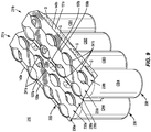
- Fig. 8 is a plan view of the exterior side 201 of a blank, generally indicated at 203, used to form a carrier 205 ( Fig. 9 ) for containing one or more containers according to a second exemplary embodiment of the disclosure.
- the blank 203 and the carrier 205 formed therefrom can have one or more substantially similar features to the blank 103 ( Fig. 1 ) and the carrier 105 ( Fig. 6 ) described above, and like or similar components are referenced with like or similar reference numbers.
- the carrier 205 formed from the blank 203 can be provided with one or more containers as a package 210 ( Fig. 9 ).
- the blank 203 includes a front portion 207 for forming a front portion 206 of the carrier 205 and a back portion 209 for forming a back portion 208 of the carrier 205.
- the front portion 207 of the blank includes a front attachment panel 231a having a container retention portion 235a defined between/proximate the fold lines 137a, 139a.
- the container retention portion 235a of the front attachment panel 231a can include container retention features that include at least pairs of longitudinally spaced container openings 241a that interrupt the respective fold lines 137a, 139a.
- Each container opening 241a is defined by a first or laterally outer curved edge portion 242a with endpoints that intersect the respective fold lines 137a, 139a, and a second or laterally inner curved edge portion 243a that extends from one endpoint to the other endpoint of the respective first curved edge portion 242a.
- the container retention portion 235a can include a laterally-spaced plurality of the pairs longitudinally-spaced container openings 241a.
- respective oblique cuts 144a, 145a extend outwardly from each respective first curved edge portion 242a to define a plurality of reconfigurable edges of the front attachment panel 231a adjacent the respective container openings 241a.
- the second curved edge portions 242a can have an irregular, e.g., wavelike, curvature such that the container openings 241a have a generally tapered profile in the direction of the respective first curved edge portion 242a to the respective second curved edge portion 243a. It will be understood that the container retention features of the front attachment panel 231a can have a different configuration without departing from the disclosure.
- the back portion 209 of the blank 203 includes a back central panel 125b, a back container retention panel or back attachment panel 231b, and a back bevel panel or back side panel 151b having associated features that are generally a mirror-image of the corresponding panels and flaps of the front portion 207 of the blank 203.
- Corresponding components e.g., panels, flaps, fold lines, cuts, etc.
- corresponding reference numbers that differ by the "a” or "b” suffix, with the "a” components corresponding to the front portion 207 of the blank 203 and the "b” components corresponding to the back portion 209 of the blank 203.
- the features of the container openings 241b of the back attachment panel 231a are best shown in Fig. 8B .
- the carrier 205 and a package 210 that includes the carrier 205 and the containers CA1, CA2, CA3, CA4, CB1, CB2, CB3, CB4 can be formed in a similar manner as that described above with respect to the carrier 105/package 110.
- the upper or top portions T of the respective containers CA1, CA2, CA3, CA4 can be at least partially received through the container openings 241a in the front attachment panel 231a such that a plurality of reconfigurable edges of the marginal portions 236a, 238a defined by the curved edge portions 242a of the container openings 241a and the oblique cuts 244a, 245a can engage, for example, a rolled rim edge or other top structure of the respective container CA1, CA2, CA3, CA4.
- portions of the container retention portion 235a of the front attachment panel 231a e.g., portions of the container retention portion 235a between adjacent container openings 241a, can flexibly reconfigure in the course of engaging respective containers.
- the side panel 151a can adhesively engage the respective containers CA1, CA2, CA3, CA4 applied along its interior surface as described above with regard to the carrier 105/package 110.
- the container retention features of the attachment panel 231b can engage the containers CB1, CB2, CB3, CB4 in a similar manner as described above with regard to the engagement of the attachment panel 231a with the containers CA1, CA2, CA3, CA4, and the side panel 151b can adhesively engage the containers CB1, CB2, CB3, CB4 in a manner similar to that described above with regard to the engagement of the side panel 151a with the containers CA1, CA2, CA3, CA4.
- the carrier 205/package 210 provides the same or similar advantages to those described above with respect to the carrier 105/package 110, such as materials savings and waste reduction in a construct that provides multiple points of adhesive attachment of the material of the blank 203/carrier 205 to the respective containers, e.g., at the central panels 125a, 125b and side panels 151a, 151b, that results in a robust structure for holding and carrying containers.
- Such a configuration also exposes portions of the containers on exterior portions of the carrier 205/package 210, e.g., the upper portions T of the respective containers through the container openings 241a, 241b for enhanced product visibility.
- the carrier 205/package 210 can have a different configuration without departing from the disclosure.
- the container openings 241a, 241b can be replaced by a plurality of laterally-spaced cuts having the form of the edge portions 143a, 143b to provide additional coverage of the top portions of the containers.
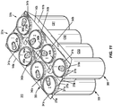
- Fig. 10 is a plan view of the exterior side 301 of a blank, generally indicated at 303, used to form a carrier 305 ( Fig. 11 ) for containing one or more containers according to a third exemplary embodiment of the disclosure.
- the blank 303 and the carrier 305 formed therefrom can have one or more substantially similar features to the blanks 103, 203 and the carriers 105, 205 described above, and like or similar components are referenced with like or similar reference numbers.
- the carrier 305 formed from the blank 303 can be provided with one or more containers as a package 310 ( Fig. 11 ).
- the blank 303 includes a front portion 307 for forming a front portion 306 of the carrier 305 and a back portion 309 for forming a back portion 308 of the carrier 305.
- the front portion 307 of the blank includes a front attachment panel 331a having a container retention portion 335a.
- the container retention portion 335a of the front attachment panel 331a is devoid of the fold lines 137a, 139a, but one of the fold lines 137a, 139a can be present without departing from the disclosure.
- the attachment panel 331a can include container retention features that include at least laterally outer container openings 341a proximate the lateral edges of the blank 303, and laterally inner container openings 342a positioned between the laterally outer container openings 341a. While the laterally outer container openings 341a are shown having a slightly different configuration than the laterally inner container openings 342a, it will be understood that the container openings 341a, 342a can have similar configurations without departing from the disclosure.
- the laterally outer container openings 341a have a generally circular profile, but can include one or more straight or chamfered edges.
- a plurality of container tabs is foldably connected to the attachment panel 331a and extends into the container opening 341a, and can include a major, e.g., relatively larger, container retention tab 343a at least partially foldably connected to the attachment panel 331a at a line of weakening or fold line 344a, and a plurality of minor, e.g., relatively smaller, container retention tabs 345a at least partially foldably connected to the attachment panel 331a at a line of weakening or fold line 346a.
- circumferentially adjacent container retention tabs 343a, 345a can be positioned to abut each other, e.g., so as to be separated by a cut, or can be circumferentially spaced apart from one another along the edge of the container opening 341a.
- the laterally inner container openings 342a can have a configuration that is generally similar to the laterally outer container openings 341a.
- the laterally inner container openings 342a can be devoid of a straight or chamfered edge, and can include a different number and/or arrangement of container retention tabs, e.g., a pair of laterally-opposed major container retention tabs 343a and a series of alternating circumferentially spaced and circumferentially abutting minor container retention tabs 345a therebetween along the edge of the container openings 342a.
- the container openings 341a, 342a can have similar or different configurations to one another, or can have a different configuration than illustrated, without departing from the disclosure.
- the container retention features of the blank 303 and the carrier 305 formed therefrom can also include respective a plurality of container engagement flaps that is foldably connected to the lateral ends of the attachment panel 331a.
- each plurality of container engagement flaps includes a pair of major, e.g., relatively larger, container engagement flaps 371a foldably connected to one another at a lateral fold line 373a, and a pair of minor, e.g., relatively smaller, container engagement flaps 375a foldably connected to the respective container engagement flaps 371a at a respective oblique fold line 377a and to the attachment panel 331a at a respective oblique fold line 379a.
- the major container engagement flaps 371a can have laterally inner free edges that at least partially form an edge of the respective container openings 341a.
- the back portion 309 of the blank 303 includes a back central panel 125b, a back container retention panel or back attachment panel 331b, and a back bevel panel or back side panel 151b having associated features that are generally a mirror-image of the corresponding panels and flaps of the front portion 307 of the blank 303.
- Corresponding components e.g., panels, flaps, fold lines, cuts, etc.
- corresponding reference numbers that differ by the "a” or "b” suffix, with the "a” components corresponding to the front portion 307 of the blank 303 and the "b” components corresponding to the back portion 309 of the blank 303.
- the features of the back attachment panel 331a are best shown in Fig. 10B .
- the carrier 305 and a package 310 that includes the carrier 305 and the containers CA1, CA2, CA3, CA4, CB1, CB2, CB3, CB4 can be formed in a similar manner as that described above with respect to the carrier 105/package 110 and carrier 205/package 210.
- the upper or top portions T of the respective containers CA1, CA2, CA3, CA4 can be at least partially received through the respective container openings 341a, 342a in the front attachment panel 331a.
- the container retention tabs 343a, 345a can contact the top portions T of respective containers such that the container retention tabs 343a, 345a are urged to fold at least partially upwardly at the respective fold lines 344a, 346a so as to be positioned to engage, for example, a rolled rim edge or other top structure of the respective container CA1, CA2, CA3, CA4.
- the container engagement flaps 375a can fold downwardly relative to the attachment panel 331a at the respective fold lines 379a to position the container engagement flaps 371a to fold relative to each other at the fold line 373a and to fold relative to the container engagement flaps 375a at the respective fold lines 377a.
- the container engagement flaps 371a are obliquely arranged relative to one another and obliquely downwardly arranged relative to the attachment panel 331a such that the laterally inner free edges of the container engagement flaps 371a are positioned to contact or engage a rolled rim or other top structure of the respective containers CA1, CA4.
- the side panel 151a can adhesively engage the respective containers CA1, CA2, CA3, CA4 applied along its interior surface as described above with regard to the carrier 105/package 110 and the carrier 205/package 210.
- the container retention features of the attachment panel 331b can engage the containers CB1, CB2, CB3, CB4 in a similar manner as described above with regard to the engagement of the attachment panel 331a with the containers CA1, CA2, CA3, CA4, and the side panel 151b can adhesively engage the containers CB1, CB2, CB3, CB4 in a manner similar to that described above with regard to the engagement of the side panel 151a with the containers CA1, CA2, CA3, CA4.
- the carrier 305/package 310 provides the same or similar advantages to those described above with respect to the carrier 105/package 110 and carrier 205/package 210, such as materials savings and waste reduction, in a construct that provides multiple points of adhesive attachment of the material of the blank 303/carrier 305 to the respective containers, e.g., at the central panels 125a, 125b and side panels 151a, 151b, that results in a robust structure for holding and carrying containers.
- Such a configuration also exposes portions of the containers on exterior portions of the carrier 305/package 310, e.g., the upper portions T of the respective containers through the container openings 341a, 341b, 342a, 342b for enhanced product visibility.
- the blank may be constructed from paperboard having a caliper so that it is heavier and more rigid than ordinary paper.
- the blank can also be constructed of other materials, such as cardboard, or any other material having properties suitable for enabling the carrier to function at least generally as described above.
- the blank can be coated with, for example, a clay coating.
- the clay coating may then be printed over with product, advertising, and other information or images.
- the blanks may then be coated with a varnish to protect information printed on the blanks.
- the blanks may also be coated with, for example, a moisture barrier layer, on either or both sides of the blanks.
- the blanks can also be laminated to or coated with one or more sheet-like materials at selected panels or panel sections.
- a tear line can include: a slit that extends partially into the material along the desired line of weakness, and/or a series of spaced apart slits that extend partially into and/or completely through the material along the desired line of weakness, or various combinations of these features.
- one type tear line is in the form of a series of spaced apart slits that extend completely through the material, with adjacent slits being spaced apart slightly so that a nick (e.g., a small somewhat bridging-like piece of the material) is defined between the adjacent slits for typically temporarily connecting the material across the tear line. The nicks are broken during tearing along the tear line.
- the nicks typically are a relatively small percentage of the tear line, and alternatively the nicks can be omitted from or torn in a tear line such that the tear line is a continuous cut line. That is, it is within the scope of the present disclosure for each of the tear lines to be replaced with a continuous slit, or the like.
- a cut line can be a continuous slit or could be wider than a slit without departing from the present disclosure.
- a fold line can be any substantially linear, although not necessarily straight, form of weakening that facilitates folding therealong. More specifically, but not for the purpose of narrowing the scope of the present disclosure, fold lines include: a score line, such as lines formed with a blunt scoring knife, or the like, which creates a crushed or depressed portion in the material along the desired line of weakness; a cut that extends partially into a material along the desired line of weakness, and/or a series of cuts that extend partially into and/or completely through the material along the desired line of weakness; and various combinations of these features. In situations where cutting is used to create a fold line, typically the cutting will not be overly extensive in a manner that might cause a reasonable user to incorrectly consider the fold line to be a tear line.
- the above embodiments may be described as having one or more panels adhered together by glue during erection of the carrier embodiments.
- glue is intended to encompass all manner of adhesives commonly used to secure carrier panels in place.
Landscapes
- Engineering & Computer Science (AREA)
- Mechanical Engineering (AREA)
- Packages (AREA)
Abstract
Description
- This application claims the benefit of
U.S. Provisional Patent Application No. 63/015,898, filed on April 27, 2020 U.S. Provisional Patent Application No. 63/022,757, filed on May 11, 2020 U.S. Provisional Patent Application No. 63/023,442, filed on May 12, 2020 - The disclosures of each of
U.S. Provisional Patent Application No. 62/779,689, filed on December 14, 2018 U.S. Provisional Patent Application No. 62/783,752, filed on December 21, 2018 U.S. Provisional Patent Application No. 62/796,830, filed on January 25, 2019 U.S. Provisional Patent Application No. 62/797,585, filed on January 28, 2019 U.S. Provisional Patent Application No. 62/810,015, filed on February 25, 2019 U.S. Provisional Patent Application No. 62/814,412, filed on March 6, 2019 U.S. Provisional Patent Application No. 62/817,120, filed on March 12, 2019 U.S. Provisional Patent Application No. 62/841,449, filed on May 1, 2019 U.S. Patent Application No. 16/426,050, filed on May 30, 2019 U.S. Patent Application No. 16/426,057, filed on May 30, 2019 U.S. Patent Application No. 16/426,060, filed on May 30, 2019 U.S. Patent Application No. 16/426,063, filed on May 30, 2019 U.S. Patent Application No. 16/426,066, filed on May 30, 2019 29/692,992, filed on May 30, 2019 29/692,993, filed on May 30, 2019 29/692,994, filed on May 30, 2019 29/692,996, filed on May 30, 2019 29/692,997, filed on May 30, 2019 U.S. Patent Application No. 16/598,282, filed on October 10, 2019 29/709,918, filed on October 18, 2019 U.S. Provisional Patent Application No. 62/952,839, filed on December 23, 2019 U.S. Provisional Patent Application No. 62/956,882, filed on January 3, 2020 U.S. Provisional Patent Application No. 62/985,997, filed on March 6, 2020 U.S. Patent Application No. 16/829,346, filed on March 25, 2020 U.S. Provisional Patent Application No. 63/015,898, filed on April 27, 2020 U.S. Provisional Patent Application No. 63/022,757, filed on May 11, 2020 U.S. Provisional Patent Application No. 63/023,442, filed on May 12, 2020 29/735,178, filed on May 19, 2020 U.S. Provisional Patent Application No. 63/031,615, filed on May 29, 2020 29/739,927, filed on June 30, 2020 29/739,929, filed on June 30, 2020 29/739,931, filed on June 30, 2020 29/739,933, filed on June 30, 2020 29/739,934, filed on June 30, 2020 - The present disclosure generally relates to cartons or carriers for holding, displaying, and/or transporting containers.
- According to one aspect, the disclosure is generally directed to a carrier for holding a plurality of containers, the carrier comprising a plurality of panels comprising at least one central panel, at least one attachment panel foldably connected to the at least one central panel and configured to receive a portion of at least one container of the plurality of containers, and at least one side panel foldably connected to the at least one attachment panel. The at least one central panel comprises a plurality of openings and is positioned between and attached to adjacent containers of the plurality of containers, and the at least one side panel is attached to at least one container of the plurality of containers.
- According to another aspect, the disclosure is generally directed to a blank for forming a carrier for holding a plurality of containers, the blank comprising a plurality of panels comprising at least one central panel, at least one attachment panel foldably connected to the at least one central panel and configured to receive a portion of at least one container of the plurality of containers, and at least one side panel foldably connected to the at least one attachment panel. The at least one central panel comprises a plurality of openings and is for being positioned between and attached to adjacent containers of the plurality of containers when the container is formed from the blank, and the at least one side panel is for being attached to at least one container of the plurality of containers when the container is formed from the blank.
- According to another aspect, the disclosure is generally directed to a method of forming a carrier for holding a plurality of containers, the method comprising obtaining a blank comprising a plurality of panels comprising at least one central panel comprising a plurality of openings, at least one attachment panel foldably connected to the at least one central panel and configured to receive a portion of at least one container of the plurality of containers, and at least one side panel foldably connected to the at least one attachment panel. The method further comprises folding the plurality of panels such that the at least one central panel is positioned between adjacent containers of the plurality of containers, attaching the at least one central panel to the adjacent containers of the plurality of containers, attaching the at least one attachment panel to at least one container of the plurality of containers, and attaching the at least one side panel to at least one container of the plurality of containers.
- According to another aspect, the disclosure is generally directed to a package comprising a plurality of containers and a carrier holding the plurality of containers. The carrier comprises a plurality of panels comprising at least one central panel, at least one attachment panel foldably connected to the at least one central panel and receiving a portion of at least one container of the plurality of containers, and at least one side panel foldably connected to the at least one attachment panel. The at least one central panel comprises a plurality of openings and is positioned between and attached to adjacent containers of the plurality of containers, and the at least one side panel is attached to at least one container of the plurality of containers.
- Those skilled in the art will appreciate the above stated advantages and other advantages and benefits of various additional embodiments reading the following detailed description of the embodiments with reference to the below-listed drawing figures. It is within the scope of the present disclosure that the above-discussed aspects be provided both individually and in various combinations.
- According to common practice, the various features of the drawings discussed below are not necessarily drawn to scale. Dimensions of various features and elements in the drawings may be expanded or reduced to more clearly illustrate the embodiments of the disclosure.
-
Fig. 1 is a schematic plan view of an outer surface of a blank for forming a carrier according to a first exemplary embodiment of the disclosure. -
Fig. 1A is an enlarged view of a portion of the blank ofFig. 1 . -
Fig. 1B is an enlarged view of another portion of the blank ofFig. 1 . -
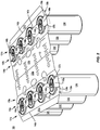
Fig. 2 is perspective view of a partially folded configuration of a carrier formed from the blank ofFig. 1 according to the first exemplary embodiment. -
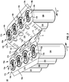
Fig. 3 is a perspective view of another partially folded configuration of a carrier formed from the blank ofFig. 1 according to the first exemplary embodiment. -
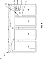
Fig. 4 is a front view of a carrier formed from the blank ofFig. 1 according to the first exemplary embodiment and having a container removed therefrom. -
Fig. 5 is a rear view of the carrier ofFig. 4 and having a container removed therefrom. -
Fig. 6 is a perspective view of a package and carrier formed from the blank ofFig. 1 according to the first exemplary embodiment. -
Fig. 7 is another perspective view of the package and carrier ofFig. 6 and showing a container being removed therefrom. -
Fig. 8 is a schematic plan view of an outer surface of a blank for forming a carrier according to a second exemplary embodiment of the disclosure. -
Fig. 8A is an enlarged view of a portion of the blank ofFig. 8 . -
Fig. 8B is an enlarged view of another portion of the blank ofFig. 8 . -
Fig. 9 is a perspective view of a package and carrier formed from the blank ofFig. 8 according to the second exemplary embodiment. -
Fig. 10 is a schematic plan view of an outer surface of a blank for forming a carrier according to a third exemplary embodiment of the disclosure. -
Fig. 10A is an enlarged view of a portion of the blank ofFig. 10 . -
Fig. 10B is an enlarged view of another portion of the blank ofFig. 10 . -
Fig. 11 is a perspective view of a package and carrier formed from the blank ofFig. 10 according to the third exemplary embodiment. - Corresponding parts are designated by corresponding reference numbers throughout the drawings.
- The present disclosure generally relates to carriers, packages, constructs, sleeves, cartons, or the like, for holding and displaying containers such as jars, bottles, cans, etc. The containers can be used for packaging food and beverage products, for example. The containers can be made from materials suitable in composition for packaging the particular food or beverage item, and the materials include, but are not limited to, glass; plastics such as PET, LDPE, LLDPE, HDPE, PP, PS, PVC, EVOH, and Nylon; and the like; aluminum and/or other metals; or any combination thereof.
- Carriers according to the present disclosure can accommodate containers of numerous different shapes. For the purpose of illustration and not for the purpose of limiting the scope of the disclosure, the following detailed description describes beverage containers (e.g., aluminum cans) at least partially disposed within the carrier embodiments. In this specification, the terms "lower," "bottom," "upper," "top," "front," and "back" indicate orientations determined in relation to fully erected carriers.
- As described herein, carriers may be formed by multiple overlapping panels, end flaps, and/or other portions of blanks. Such panels, end flaps, and/or other portions of the blank can be designated in relative terms to one another, e.g., "first", "second", "third", etc., in sequential or non-sequential reference, without departing from the disclosure.
-
Fig. 1 shows a schematic plan view of anexterior side 101 of a blank 103 used to form a carrier 105 (Fig. 6 ) in accordance with a first exemplary embodiment of the disclosure. As shown inFig. 6 , thecarrier 105 is sized to contain or support eight containers, with four containers CA1, CA2, CA3, CA4 being attached to afront portion 106 of thecarrier 105 and four containers CB1, CB2, CB3, CB4 being attached to aback portion 108 of thecarrier 105. In the illustrated embodiment, the containers CA1, CA2, CA3, CA4, CB1, CB2, CB3, CB4 can be beverage cans, or could be any other suitable type and size of container without departing from the disclosure. Thecarrier 105 can be sized and shaped to hold more or less than eight containers. - In one embodiment, the
front portion 106 and theback portion 108 of thecarrier 105 each have four containers, and in other embodiments, thefront portion 106 and theback portion 108 of thecarrier 105 can carry more or less than four containers without departing from the disclosure. Thecarrier 105 can be provided together with one or more containers as a package 110 (Fig. 6 ). - As shown in
Fig. 1 , the blank 103 has a longitudinal axis L1 and a lateral axis L2. The blank 103 has afront portion 107 for forming thefront portion 106 of thecarrier 105, and aback portion 109 for forming theback portion 108 of thecarrier 105. Thefront portion 107 and theback portion 109 of the blank 103 are foldably connected at alateral fold line 112 that forms a lateral centerline CL of the blank 103, as shown. As discussed further below, the blank 103 is at least partially formed into thecarrier 105 by folding the blank 103 at thefold line 112 along the centerline CL so that thefront portion 107 and theback portion 109 of the blank 103 are overlapped in at least partial face-to-face contact. - In the illustrated embodiment, the
front portion 107 of the blank 103 comprises a frontcentral panel 125a having a first front row RF1 of laterally spaced adhesive orglue openings 127a, and a second front row RF2 of the laterally spaced adhesive orglue openings 127a. The top edges of therespective glue openings 127a of the first row RF1 are spaced a longitudinal distance D1 apart from thefold line 112 that is less than a longitudinal distance D2 that the top edges of therespective glue openings 127a of the second row RF2 are spaced apart from thefold line 112. - A front container retention panel or
front attachment panel 131a is foldably connected to the frontcentral panel 125a at alateral fold line 133a, and includes acontainer retention portion 135a that is at least partially defined between a pair of longitudinally-spacedlateral fold lines cuts container openings 141a. - As best shown in
Fig. 1A , theattachment panel 131a can include container retention features that include at least laterally-spacedcontainer openings 141a are defined in respective cuts in the blank 103 that define a pair of laterally spacedcurved edge portions 142a that intersect respective longitudinally spacedcurved edge portions 143a to form therespective container openings 141a. - The
edge portions 142a of the blank 103 around thecontainer openings 141a, as shown, can have a generally U-shaped or generally V-shaped configuration so as to define a pair of lateralcontainer retention tabs 148a that protrude/extend into the respective laterally-spacedcontainer openings 141a. - As also shown,
respective oblique cuts curved edge portion 143a to define a plurality of reconfigurable edges of thefront attachment panel 131a adjacent therespective container openings 141a. - As shown, an interior
marginal portion 136a of theattachment panel 131a is defined between thefold lines marginal portion 138a of theattachment panel 131a is defined between thefold line 139a and alateral fold line 140a. - A bevel or
front side panel 151a, as shown, is foldably connected to thefront attachment panel 131a at thelateral fold line 140a, and defines a lateral free edge of the blank 103. - The blank 103 can include handle features that include at least a pair of
handle openings 130a that interrupts thefold line 133a and that extends from a portion of the frontcentral panel 125a into a portion of thefront attachment panel 131a. Thehandle openings 130a can be formed by one or more cuts that include one or more curved and/or angled portions. Ahandle reinforcement tab 161a, as shown, can be foldably connected to thefront attachment panel 131a at respectivelongitudinal fold lines 163a and can be positioned to extend into therespective handle openings 130a. - As also shown, the handle features can include a
handle opening 132a that can be positioned between thehandle openings 130a, and that is formed in the frontcentral panel 125a by one or more cuts that include one or more curved and/or angled portions. A pair ofhandle reinforcement tabs 165a can also be at least partially formed by respectivecurved cuts 167a and separated from one another at a longitudinal cut. Thehandle reinforcement tabs 165a, as shown, can be foldably connected to thefront attachment panel 131a at respectivelongitudinal fold lines 169a and can be positioned abutting thehandle opening 132a. - The
carrier 105 can have a different arrangement of handle features, or can be devoid of handle features, without departing from the disclosure. - In the illustrated embodiment, the
back portion 109 of the blank 103 includes a backcentral panel 125b, a back container retention panel or backattachment panel 131b, and a back bevel panel or backside panel 151b having associated features that are generally a mirror-image of the corresponding panels and flaps of thefront portion 107 of the blank 103. Corresponding components (e.g., panels, flaps, fold lines, cuts, etc.) have been designated by corresponding reference numbers that differ by the "a" or "b" suffix, with the "a" components corresponding to thefront portion 107 of the blank 103 and the "b" components corresponding to theback portion 109 of the blank 103. The features of theback attachment panel 131a are best shown inFig. 1B . - As shown, the back
central panel 125a includes a first back lateral row ofglue openings 128 that at least partially interrupt thefold line 112 and have an upper edge spaced a longitudinal distance D3 from thefold line 112. The backcentral panel 125b also includes a second back lateral row RB2 ofglue openings 127b with an upper edge spaced apart a longitudinal distance D4 from thefold line 112, the longitudinal distance D4 being greater than the longitudinal distance D3. - In the illustrated embodiment, the
glue openings glue openings 128 can have a generally semicircular/semi-ovoid configuration. It will be understood that one or more of theglue openings Fig. 1 , e.g., generally circular, generally oblong, generally semicircular/semi-ovoid, generally rectangular, etc., without departing from the disclosure. - In this regard, the blank 103 is provided with front rows RF1 and RF2 of respective laterally-spaced
front glue openings 127a that are spaced respective longitudinal distances D1, D2 from the centerline CL, and back rows RB1 and RB2 of respective laterally-spacedback glue openings glue openings carrier 105 from the blank 103, the longitudinal centerline CL/fold line 112 can form a bottom edge of thecentral panels - As described herein, the arrangement of the
glue openings carrier 105, theglue openings central panel 125b upon which the respective containers CA1, CA2, CA3, CA4 can be attached and theglue openings central panel 125a upon which the respective containers CB1, CB2, CB3, CB4 can be attached. Such an arrangement of theglue openings carrier 105. It will be understood that theglue openings - Any of the panels, flaps, fold lines, cuts, or other features could be otherwise shaped, arranged, and/or omitted from the blank 103 without departing from the disclosure. The blank 103 could be sized and/or shaped to accommodate more or less than eight containers without departing from this disclosure.
- As shown in
Figs. 2 and3 , the blank 103 can be positioned with theexterior surface 101 facing upwardly and such that an underside or interior surface of the blank 103 is positioned facing the containers CA1, CA2, CA3, CA4, CB1, CB2, CB3, CB4. The blank 103 can be placed atop the containers CA1, CA2, CA3, CA4, CB1, CB2, CB3, CB4 such that thecontainer retention portion 135a of thefront attachment panel 131a overlies the containers CA1, CA2, CA3, CA4 and such that thecontainer retention portion 135b of the back attachment panel 13 1b overlies the containers CB1, CB2, CB3, CB4. Further downward positioning of theattachment panels container retention portions - For example, as the
front attachment panel 131a is lowered or urged downwardly onto the containers CA1, CA2, CA3, CA4, upper or top portions T of the respective containers CA1, CA2, CA3, CA4 can be at least partially received through thecontainer openings 141a in thefront attachment panel 131a. In such an arrangement, thecontainer retention tabs 148a can engage, for example, a recessed portion of a rim or other top structure of the respective container CA1, CA2, CA3, CA4 and such that a plurality of reconfigurable edges of themarginal portions curved edge portions 143a andoblique cuts - It will be understood that portions of the
container retention portion 135a of thefront attachment panel 131a, e.g., portions of thecontainer retention portion 135a betweenadjacent container openings 141a, can flexibly reconfigure in the course of engaging respective containers. - In this regard, the top portions T of the respective containers CA1, CA2, CA3, CA4 can protrude through/be partially exposed through the
respective container openings 141a so as to be visible by a customer or operator. - Such reconfiguration of the corresponding portions of the
back attachment panel 131b can occur as theback attachment panel 131b is lowed or urged downwardly onto the containers CB1, CB2, CB3, CB4. During the above-described engagement of the respectivecontainer retention portions marginal portions attachment panel 131a can fold at least partially downwardly at therespective fold lines marginal portions attachment panel 131b can fold at least partially downwardly at therespective fold lines - Still referring to
Figs. 2 and3 , the frontcentral panel 125a and the backcentral panel 125b can be folded at thefold line 112 such that the frontcentral panel 125a and the backcentral panel 125b are brought into at least partial face-to-face contact in the direction of the respective arrows A1, A2 to be positioned between respective adjacent containers and such that therespective glue openings 127a andglue openings front glue openings 127a and the respective rows RB1, RB2 of respectiveback glue openings fold line 112/lateral centerline CL as described above. - In this regard, and with additional reference to
Figs. 4 and5 , thecentral panels central panel 125a overlaps each of theglue openings central panel 125b overlaps each of theglue openings 127a to provide communication between thecentral panels central panels central panels respective attachment panels respective fold lines - An adhesive glue G (
Fig. 1 ) can be provided to adhere the containers CA1, CA2, CA3, CA4 to respective portions of thecentral panel 125b exposed through therespective glue openings 127a and the glue G can be provided to adhere the containers CB1, CB2, CB3, CB4 to respective portions of thecentral panel 125a exposed through therespective glue openings respective glue openings central panel central panel - The attachment of the containers CA1, CA2, CA3, CA4, CB1, CB2, CB3, CB4 to the respective
central panel carrier 105 under their own weight, in addition to or alternative to the container retention and support provided by the respectivecontainer retention portions central panel - Such enhanced attachment of the respective containers to the respective
central panels carrier 105, e.g., by providing opposing adhesive forces on the respectivecentral panels central panels carrier 105 is lifted, the containers CA1, CA2, CA3, CA4 can at least partially pull the portions of the backcentral panel 125b to which they are attached through therespective glue openings 127a toward the frontcentral panel 125a under the at least partial weight of the containers CA1, CA2, CA3, CA4. Respective portions of the frontcentral panel 125a can be pulled toward the backcentral panel 125b through therespective glue openings - With additional reference to
Fig. 6 , thefront side panel 151a can be folded/urged downwardly at thefold line 140a in the direction of the arrow A3, for example, to be at an oblique arrangement relative to the containers CA1, CA2, CA3, CA4, CB1, CB2, CB3, CB4. Similarly, theback side panel 151b can be folded/urged downwardly at thefold line 140b in the direction of the arrow A4 into an oblique arrangement with the containers CA1, CA2, CA3, CA4, CB1, CB2, CB3, CB4. - Such downward movement of the
side panels side panels side panels side panels - Accordingly, the attachment of the
side panels package 110/carrier 105, and can provide enhanced integrity to thepackage 110/carrier 105. In one embodiment, one or more of the containers CA1, CA2, CA3, CA4, CB1, CB2, CB3, CB4 can be attached to arespective side panel central panels attachment panels - The glue G described herein can be, for example, a hot melt adhesive, a high tack glue, an epoxy, a polymeric cement, etc., or combinations thereof. The glue G can have a different arrangement without departing from the disclosure. For example, in one embodiment, the glue G can be applied to one or more portions of the interior surface of the blank 103/
carrier 105. - In another embodiment, the glue G can have a foam or foamed configuration, e.g., such that pockets of fluids such as gas are interspersed with solid, semi-solid, and/or liquid components of adhesive. In this regard, the glue G can be injected/infused with a fluid, e.g., gaseous, component that influences the glue G to expand from an originally-defined volume, over a change in time, to occupy a larger volume. In one embodiment, the glue G can comprise about 50% solid/semi-solid/liquid adhesive and about 50% gaseous components.
- In other embodiments, the glue G can comprise a different ratio of adhesive to gaseous components, for example, about 10% adhesive/about 90% gaseous components, about 20% adhesive/about 80% gaseous components, about 30% adhesive/about 70% gaseous components, about 40% adhesive/about 60% gaseous components, about 60% adhesive/about 40% gaseous components, about 70% adhesive/about 30% gaseous components, about 80% adhesive/about 20% gaseous components, about 90% adhesive/about 10% gaseous components, or other integer or non-integer percentage ratios therebetween. The glue G can be any suitable adhesive without departing from the disclosure.
- Upon formation of the
package 110/carrier 105 as shown inFig. 6 , and with additional reference toFig. 7 , respective containers CA1, CA2, CA3, CA4, CB1, CB2, CB3, CB4 can be removed from thecarrier 105 by disengaging the container from arespective attachment panel respective container opening respective attachment panel central panel respective side panel - Peeling or pulling the containers CA1, CA2, CA3, CA4, CB1, CB2, CB3, CB4 away from a respective
central panel respective side panel central panel respective side panel central panel respective side panel central panel respective side panel - It will be understood that a different number of rows or arrangements of glue openings can be provided without departing from the disclosure, and that the central panels can be sized and configured to accommodate such arrangements. In one embodiment, the
central panels central panel central panels respective glue openings glue openings 127a as well as portions of the respectivecentral panels central panels - Still referring to
Fig. 6 , thepackage 110/carrier 105 can be grasped by a consumer by inserting one or more of his or her fingers in one or more of the both handleopenings respective attachment panel respective handle openings respective handle openings carrier 105 such that the consumer can engage the carrier from multiple orientations, e.g., a lateral orientation or a longitudinal orientation, or orientations therebetween. - In addition, one or more portions of the respective
handle reinforcement tabs respective fold lines carrier 105 and/or to provide separation among adjacent containers. - The
carrier 105/package 110 described above has a compact structure that can, for example, provide materials savings and waste reduction. Additionally, the arrangement of the glue G among the containers CA1, CA2, CA3, CA4, CB1, CB2, CB3, CB4 as well as thecentral panels side panels package 110/carrier 105 as well as exposure of the top portions T of the respective containers through thecontainer openings carrier 105/package 110. - It will be understood that the
carrier 105/package 110 can have a different configuration without departing from the disclosure. For example, in one embodiment, thecontainer openings curved edge portions -
Fig. 8 is a plan view of theexterior side 201 of a blank, generally indicated at 203, used to form a carrier 205 (Fig. 9 ) for containing one or more containers according to a second exemplary embodiment of the disclosure. The blank 203 and thecarrier 205 formed therefrom can have one or more substantially similar features to the blank 103 (Fig. 1 ) and the carrier 105 (Fig. 6 ) described above, and like or similar components are referenced with like or similar reference numbers. Thecarrier 205 formed from the blank 203 can be provided with one or more containers as a package 210 (Fig. 9 ). - As shown, the blank 203 includes a
front portion 207 for forming afront portion 206 of thecarrier 205 and aback portion 209 for forming aback portion 208 of thecarrier 205. Thefront portion 207 of the blank includes afront attachment panel 231a having acontainer retention portion 235a defined between/proximate thefold lines - As best shown in
Fig. 8A , thecontainer retention portion 235a of thefront attachment panel 231a can include container retention features that include at least pairs of longitudinally spacedcontainer openings 241a that interrupt therespective fold lines container opening 241a, as shown, is defined by a first or laterally outercurved edge portion 242a with endpoints that intersect therespective fold lines curved edge portion 243a that extends from one endpoint to the other endpoint of the respective firstcurved edge portion 242a. In the illustrated embodiment, thecontainer retention portion 235a can include a laterally-spaced plurality of the pairs longitudinally-spacedcontainer openings 241a. - As also shown,
respective oblique cuts curved edge portion 242a to define a plurality of reconfigurable edges of thefront attachment panel 231a adjacent therespective container openings 241a. - In one embodiment, the second
curved edge portions 242a can have an irregular, e.g., wavelike, curvature such that thecontainer openings 241a have a generally tapered profile in the direction of the respective firstcurved edge portion 242a to the respective secondcurved edge portion 243a. It will be understood that the container retention features of thefront attachment panel 231a can have a different configuration without departing from the disclosure. - In the illustrated embodiment, the
back portion 209 of the blank 203 includes a backcentral panel 125b, a back container retention panel or backattachment panel 231b, and a back bevel panel or backside panel 151b having associated features that are generally a mirror-image of the corresponding panels and flaps of thefront portion 207 of the blank 203. Corresponding components (e.g., panels, flaps, fold lines, cuts, etc.) have been designated by corresponding reference numbers that differ by the "a" or "b" suffix, with the "a" components corresponding to thefront portion 207 of the blank 203 and the "b" components corresponding to theback portion 209 of the blank 203. The features of thecontainer openings 241b of theback attachment panel 231a are best shown inFig. 8B . - Referring additionally to
Fig. 9 , thecarrier 205 and apackage 210 that includes thecarrier 205 and the containers CA1, CA2, CA3, CA4, CB1, CB2, CB3, CB4 can be formed in a similar manner as that described above with respect to thecarrier 105/package 110. - With regard to the container retention features of the
attachment panel 231a, the upper or top portions T of the respective containers CA1, CA2, CA3, CA4 can be at least partially received through thecontainer openings 241a in thefront attachment panel 231a such that a plurality of reconfigurable edges of themarginal portions curved edge portions 242a of thecontainer openings 241a and the oblique cuts 244a, 245a can engage, for example, a rolled rim edge or other top structure of the respective container CA1, CA2, CA3, CA4. - It will be understood that portions of the
container retention portion 235a of thefront attachment panel 231a, e.g., portions of thecontainer retention portion 235a betweenadjacent container openings 241a, can flexibly reconfigure in the course of engaging respective containers. - Furthermore, the
side panel 151a can adhesively engage the respective containers CA1, CA2, CA3, CA4 applied along its interior surface as described above with regard to thecarrier 105/package 110. - The container retention features of the
attachment panel 231b can engage the containers CB1, CB2, CB3, CB4 in a similar manner as described above with regard to the engagement of theattachment panel 231a with the containers CA1, CA2, CA3, CA4, and theside panel 151b can adhesively engage the containers CB1, CB2, CB3, CB4 in a manner similar to that described above with regard to the engagement of theside panel 151a with the containers CA1, CA2, CA3, CA4. - The
carrier 205/package 210 provides the same or similar advantages to those described above with respect to thecarrier 105/package 110, such as materials savings and waste reduction in a construct that provides multiple points of adhesive attachment of the material of the blank 203/carrier 205 to the respective containers, e.g., at thecentral panels side panels carrier 205/package 210, e.g., the upper portions T of the respective containers through thecontainer openings - It will be understood that the
carrier 205/package 210 can have a different configuration without departing from the disclosure. For example, in one embodiment, thecontainer openings edge portions -
Fig. 10 is a plan view of theexterior side 301 of a blank, generally indicated at 303, used to form a carrier 305 (Fig. 11 ) for containing one or more containers according to a third exemplary embodiment of the disclosure. The blank 303 and thecarrier 305 formed therefrom can have one or more substantially similar features to theblanks carriers carrier 305 formed from the blank 303 can be provided with one or more containers as a package 310 (Fig. 11 ). - As shown, the blank 303 includes a
front portion 307 for forming afront portion 306 of thecarrier 305 and aback portion 309 for forming aback portion 308 of thecarrier 305. Thefront portion 307 of the blank includes afront attachment panel 331a having acontainer retention portion 335a. As shown, thecontainer retention portion 335a of thefront attachment panel 331a is devoid of thefold lines fold lines - With additional reference to
Fig. 10A , theattachment panel 331a can include container retention features that include at least laterallyouter container openings 341a proximate the lateral edges of the blank 303, and laterallyinner container openings 342a positioned between the laterallyouter container openings 341a. While the laterallyouter container openings 341a are shown having a slightly different configuration than the laterallyinner container openings 342a, it will be understood that thecontainer openings - The laterally
outer container openings 341a, as shown, have a generally circular profile, but can include one or more straight or chamfered edges. A plurality of container tabs is foldably connected to theattachment panel 331a and extends into thecontainer opening 341a, and can include a major, e.g., relatively larger,container retention tab 343a at least partially foldably connected to theattachment panel 331a at a line of weakening or foldline 344a, and a plurality of minor, e.g., relatively smaller,container retention tabs 345a at least partially foldably connected to theattachment panel 331a at a line of weakening or foldline 346a. - As shown, circumferentially adjacent
container retention tabs container opening 341a. - As also shown in
Fig. 10A , the laterallyinner container openings 342a can have a configuration that is generally similar to the laterallyouter container openings 341a. In the illustrated embodiment, the laterallyinner container openings 342a can be devoid of a straight or chamfered edge, and can include a different number and/or arrangement of container retention tabs, e.g., a pair of laterally-opposed majorcontainer retention tabs 343a and a series of alternating circumferentially spaced and circumferentially abutting minorcontainer retention tabs 345a therebetween along the edge of thecontainer openings 342a. It will be understood that thecontainer openings - Still referring to
Figs. 10 and10A , the container retention features of the blank 303 and thecarrier 305 formed therefrom can also include respective a plurality of container engagement flaps that is foldably connected to the lateral ends of theattachment panel 331a. As shown, each plurality of container engagement flaps includes a pair of major, e.g., relatively larger,container engagement flaps 371a foldably connected to one another at alateral fold line 373a, and a pair of minor, e.g., relatively smaller,container engagement flaps 375a foldably connected to the respectivecontainer engagement flaps 371a at a respectiveoblique fold line 377a and to theattachment panel 331a at a respectiveoblique fold line 379a. As shown, the majorcontainer engagement flaps 371a can have laterally inner free edges that at least partially form an edge of therespective container openings 341a. - In the illustrated embodiment, the
back portion 309 of the blank 303 includes a backcentral panel 125b, a back container retention panel or backattachment panel 331b, and a back bevel panel or backside panel 151b having associated features that are generally a mirror-image of the corresponding panels and flaps of thefront portion 307 of the blank 303. Corresponding components (e.g., panels, flaps, fold lines, cuts, etc.) have been designated by corresponding reference numbers that differ by the "a" or "b" suffix, with the "a" components corresponding to thefront portion 307 of the blank 303 and the "b" components corresponding to theback portion 309 of the blank 303. The features of theback attachment panel 331a are best shown inFig. 10B . - Referring additionally to
Fig. 11 , thecarrier 305 and apackage 310 that includes thecarrier 305 and the containers CA1, CA2, CA3, CA4, CB1, CB2, CB3, CB4 can be formed in a similar manner as that described above with respect to thecarrier 105/package 110 andcarrier 205/package 210. - With regard to the container retention features of the
carrier 305, the upper or top portions T of the respective containers CA1, CA2, CA3, CA4 can be at least partially received through therespective container openings front attachment panel 331a. During such movement, thecontainer retention tabs container retention tabs respective fold lines - In addition, the
container engagement flaps 375a can fold downwardly relative to theattachment panel 331a at therespective fold lines 379a to position thecontainer engagement flaps 371a to fold relative to each other at thefold line 373a and to fold relative to thecontainer engagement flaps 375a at therespective fold lines 377a. In the illustrated arrangement, thecontainer engagement flaps 371a are obliquely arranged relative to one another and obliquely downwardly arranged relative to theattachment panel 331a such that the laterally inner free edges of thecontainer engagement flaps 371a are positioned to contact or engage a rolled rim or other top structure of the respective containers CA1, CA4. - Furthermore, the
side panel 151a can adhesively engage the respective containers CA1, CA2, CA3, CA4 applied along its interior surface as described above with regard to thecarrier 105/package 110 and thecarrier 205/package 210. - The container retention features of the
attachment panel 331b can engage the containers CB1, CB2, CB3, CB4 in a similar manner as described above with regard to the engagement of theattachment panel 331a with the containers CA1, CA2, CA3, CA4, and theside panel 151b can adhesively engage the containers CB1, CB2, CB3, CB4 in a manner similar to that described above with regard to the engagement of theside panel 151a with the containers CA1, CA2, CA3, CA4. - The
carrier 305/package 310 provides the same or similar advantages to those described above with respect to thecarrier 105/package 110 andcarrier 205/package 210, such as materials savings and waste reduction, in a construct that provides multiple points of adhesive attachment of the material of the blank 303/carrier 305 to the respective containers, e.g., at thecentral panels side panels carrier 305/package 310, e.g., the upper portions T of the respective containers through thecontainer openings - It will be understood that the blanks, carriers, and packages described herein can be provided in different configurations without departing from the disclosure.
- In general, the blank may be constructed from paperboard having a caliper so that it is heavier and more rigid than ordinary paper. The blank can also be constructed of other materials, such as cardboard, or any other material having properties suitable for enabling the carrier to function at least generally as described above. The blank can be coated with, for example, a clay coating. The clay coating may then be printed over with product, advertising, and other information or images. The blanks may then be coated with a varnish to protect information printed on the blanks. The blanks may also be coated with, for example, a moisture barrier layer, on either or both sides of the blanks. The blanks can also be laminated to or coated with one or more sheet-like materials at selected panels or panel sections.
- As an example, a tear line can include: a slit that extends partially into the material along the desired line of weakness, and/or a series of spaced apart slits that extend partially into and/or completely through the material along the desired line of weakness, or various combinations of these features. As a more specific example, one type tear line is in the form of a series of spaced apart slits that extend completely through the material, with adjacent slits being spaced apart slightly so that a nick (e.g., a small somewhat bridging-like piece of the material) is defined between the adjacent slits for typically temporarily connecting the material across the tear line. The nicks are broken during tearing along the tear line. The nicks typically are a relatively small percentage of the tear line, and alternatively the nicks can be omitted from or torn in a tear line such that the tear line is a continuous cut line. That is, it is within the scope of the present disclosure for each of the tear lines to be replaced with a continuous slit, or the like. For example, a cut line can be a continuous slit or could be wider than a slit without departing from the present disclosure.
- In accordance with the exemplary embodiments, a fold line can be any substantially linear, although not necessarily straight, form of weakening that facilitates folding therealong. More specifically, but not for the purpose of narrowing the scope of the present disclosure, fold lines include: a score line, such as lines formed with a blunt scoring knife, or the like, which creates a crushed or depressed portion in the material along the desired line of weakness; a cut that extends partially into a material along the desired line of weakness, and/or a series of cuts that extend partially into and/or completely through the material along the desired line of weakness; and various combinations of these features. In situations where cutting is used to create a fold line, typically the cutting will not be overly extensive in a manner that might cause a reasonable user to incorrectly consider the fold line to be a tear line.
- The above embodiments may be described as having one or more panels adhered together by glue during erection of the carrier embodiments. The term "glue" is intended to encompass all manner of adhesives commonly used to secure carrier panels in place.
- The foregoing description of the disclosure illustrates and describes various exemplary embodiments. Various additions, modifications, changes, etc., could be made to the exemplary embodiments without departing from the spirit and scope of the disclosure. It is intended that all matter contained in the above description or shown in the accompanying drawings shall be interpreted as illustrative and not in a limiting sense. Additionally, the disclosure shows and describes only selected embodiments of the disclosure, but the disclosure is capable of use in various other combinations, modifications, and environments and is capable of changes or modifications within the scope of the inventive concept as expressed herein, commensurate with the above teachings, and/or within the skill or knowledge of the relevant art. Furthermore, certain features and characteristics of each embodiment may be selectively interchanged and applied to other illustrated and non-illustrated embodiments of the disclosure.
Claims (31)
- A carrier for holding a plurality of containers, the carrier comprising:a plurality of panels comprising at least one central panel, at least one attachment panel foldably connected to the at least one central panel and configured to receive a portion of at least one container of the plurality of containers, and at least one side panel foldably connected to the at least one attachment panel,the at least one central panel comprises a plurality of openings and is positioned between and attached to adjacent containers of the plurality of containers, and the at least one side panel is attached to at least one container of the plurality of containers.
- The carrier of claim 1, wherein the at least one side panel is adhered to adjacent containers of the plurality of containers.
- The carrier of claim 2, wherein the at least one side panel is adhered to adjacent containers of the plurality of containers with glue.
- The carrier of claim 2, wherein the at least one central panel is a front central panel, the at least one attachment panel is a front attachment panel attached to adjacent containers of the plurality of containers, the at least one side panel is a front side panel, and the carrier further comprises a back central panel foldably connected to the front central panel, a back attachment panel foldably connected to the back central panel, and a back side panel foldably connected to the back attachment panel, the back attachment panel is attached to adjacent containers of the plurality of containers.
- The carrier of claim 3, wherein the at least one central panel is adhered to adjacent containers of the plurality of containers with glue.
- The carrier of claim 1, wherein the plurality openings comprises a first row of openings and a second row of openings spaced apart from the first row of openings, the first row of openings is spaced a first distance from a bottom edge of the at least one central panel, and the second row of openings is spaced a second distance from the bottom edge of the at least one central panel, the second distance is greater than the first distance.
- The carrier of claim 6, wherein the at least one central panel is a front central panel, the plurality of panels further comprises a back central panel, the at least one attachment panel is a front attachment panel foldably connected to the front central panel, and the plurality of panels further comprises a back attachment panel foldably connected to the back central panel, the plurality of openings is a first plurality of openings in the front central panel, and the back central panel comprises a second plurality of openings such that the first plurality of openings are in communication with the back central panel and the second plurality of openings are in communication with the front central panel.
- The carrier of claim 7, wherein the first plurality of openings is offset from the second plurality of openings.
- The carrier of claim 8, wherein the front central panel and the back central panel are in at least partial face-to-face contact such that a respective portion of the back central panel is exposed through the first plurality of openings and a respective portion of the front central panel is exposed through the second plurality of openings, the respective portion of the front central panel and the respective portion of the back central panel are for receiving an adhesive.
- The carrier of claim 1, wherein the at least one attachment panel comprises at least one container opening for at least partially receiving a container of the plurality of containers.
- The carrier of claim 10, wherein the at least one container opening defines at least one container retention tab extending into the at least one container opening.
- The carrier of claim 10, wherein the at least one container opening comprises a pair of longitudinally-spaced container openings.
- The carrier of claim 10, wherein the at least one container opening comprises a plurality of pairs of longitudinally-spaced container openings.
- The carrier of claim 10, wherein a plurality of container retention tabs is foldably connected to the at least one attachment panel and extend into the at least one container opening.
- The carrier of claim 14, wherein at least one container retention tab of the plurality of container retention tabs is positioned circumferentially abutting an adjacent container retention tab of the plurality of container retention tabs.
- The carrier of claim 14, wherein at least one container retention tab of the plurality of container retention tabs is positioned circumferentially spaced apart from an adjacent container retention tab of the plurality of container retention tabs.
- A blank for forming a carrier for holding a plurality of containers, the blank comprising:a plurality of panels comprising at least one central panel, at least one attachment panel foldably connected to the at least one central panel and configured to receive a portion of at least one container of the plurality of containers, and at least one side panel foldably connected to the at least one attachment panel,the at least one central panel comprises a plurality of openings and is for being positioned between and attached to adjacent containers of the plurality of containers when the container is formed from the blank, and the at least one side panel is for being attached to at least one container of the plurality of containers when the container is formed from the blank.
- The blank of claim 17, wherein the at least one side panel is for being adhered to adjacent containers of the plurality of containers.
- The blank of claim 18, wherein the at least one side panel is for being adhered to adjacent containers of the plurality of containers with glue.
- The blank of claim 18, wherein the at least one central panel is a front central panel, the at least one attachment panel is a front attachment panel attached to adjacent containers of the plurality of containers, the at least one side panel is a front side panel, and the carrier further comprises a back central panel foldably connected to the front central panel, a back attachment panel foldably connected to the back central panel, and a back side panel foldably connected to the back attachment panel, the back attachment panel is for being attached to adjacent containers of the plurality of containers.
- The blank of claim 17, wherein the plurality of openings comprises a first row of openings and a second row of openings spaced apart from the first row of openings, the first row of openings is for being spaced a first distance from a bottom edge of the at least one central panel when the carrier is formed from the blank, and the second row of openings is for being spaced a second distance from the bottom edge of the at least one central panel when the carrier is formed from the blank, the second distance is greater than the first distance,
the at least one central panel is a front central panel, the plurality of panels further comprises a back central panel, the at least one attachment panel is a front attachment panel foldably connected to the front central panel, and the plurality of panels further comprises a back attachment panel foldably connected to the back central panel, the plurality of openings is a first plurality of openings in the front central panel, and the back central panel comprises a second plurality of openings such that the first plurality of openings are in communication with the back central panel and the second plurality of openings are in communication with the front central panel when the carrier is formed from the blank,
the first plurality of openings is for being offset from the second plurality of openings when the carrier is formed from the blank,
the front central panel and the back central panel are for being in at least partial face-to-face contact when the carrier is formed from the blank such that a respective portion of the back central panel is exposed through the first plurality of openings and a respective portion of the front central panel is exposed through the second plurality of openings, the respective portion of the front central panel and the respective portion of the back central panel are for receiving an adhesive. - A method of forming a carrier for holding a plurality of containers, the method comprising:obtaining a blank comprising a plurality of panels comprising at least one central panel comprising a plurality of openings, at least one attachment panel foldably connected to the at least one central panel and configured to receive a portion of at least one container of the plurality of containers, and at least one side panel foldably connected to the at least one attachment panel;folding the plurality of panels such that the at least one central panel is positioned between adjacent containers of the plurality of containers;attaching the at least one central panel to the adjacent containers of the plurality of containers;attaching the at least one attachment panel to at least one container of the plurality of containers; andattaching the at least one side panel to at least one container of the plurality of containers.
- The method of claim 22, wherein the at least one side panel is adhered to adjacent containers of the plurality of containers.
- The method of claim 23, wherein the at least one side panel is adhered to adjacent containers of the plurality of containers with glue.
- The method of claim 23, wherein the at least one central panel is a front central panel, the at least one attachment panel is a front attachment panel attached to adjacent containers of the plurality of containers, the at least one side panel is a front side panel, and the blank further comprises a back central panel foldably connected to the front central panel, a back attachment panel foldably connected to the back central panel, and a back side panel foldably connected to the back attachment panel, the method further comprises attaching the back attachment panel to adjacent containers of the plurality of containers.
- The method of claim 22, wherein the plurality of openings comprises a first row of openings and a second row of openings spaced apart from the first row of openings, the folding the plurality of panels comprises positioning the first row of openings spaced a first distance from a bottom edge of the at least one central panel, and the folding the plurality of panels comprises positioning the second row of openings spaced a second distance from the bottom edge of the at least one central panel, the second distance is greater than the first distance,
the at least one central panel is a front central panel, the plurality of panels further comprises a back central panel, the at least one attachment panel is a front attachment panel foldably connected to the front central panel, and the plurality of panels further comprises a back attachment panel foldably connected to the back central panel, the plurality of openings is a first plurality of openings in the front central panel, and the back central panel comprises a second plurality of openings, the folding the plurality of panels comprises positioning the first plurality of openings in communication with the back central panel and positioning the second plurality of openings in communication with the front central panel,
the first plurality of openings is offset from the second plurality of openings,
the folding the plurality of panels comprises positioning the front central panel and the back central panel in at least partial face-to-face contact such that a respective portion of the back central panel is exposed through the first plurality of openings and a respective portion of the front central panel is exposed through the second plurality of openings, the respective portion of the front central panel and the respective portion of the back central panel are for receiving an adhesive. - A package, comprising:a plurality of containers; anda carrier holding the plurality of containers, the carrier comprising:a plurality of panels comprising at least one central panel, at least one attachment panel foldably connected to the at least one central panel and receiving a portion of at least one container of the plurality of containers, and at least one side panel foldably connected to the at least one attachment panel,the at least one central panel comprises a plurality of openings and is positioned between and attached to adjacent containers of the plurality of containers, and the at least one side panel is attached to at least one container of the plurality of containers.
- The package of claim 27, wherein the at least one side panel is adhered to adjacent containers of the plurality of containers.
- The package of claim 28, wherein the at least one side panel is adhered to adjacent containers of the plurality of containers with glue.
- The package of claim 28, wherein the at least one central panel is a front central panel, the at least one attachment panel is a front attachment panel attached to adjacent containers of the plurality of containers, the at least one side panel is a front side panel, and the carrier further comprises a back central panel foldably connected to the front central panel, a back attachment panel foldably connected to the back central panel, and a back side panel foldably connected to the back attachment panel, the back attachment panel is attached to adjacent containers of the plurality of containers.
- The package of claim 27, wherein the plurality openings comprises a first row of openings and a second row of openings spaced apart from the first row of openings, the first row of openings is spaced a first distance from a bottom edge of the at least one central panel, and the second row of openings is spaced a second distance from the bottom edge of the at least one central panel, the second distance is greater than the first distance,
the at least one central panel is a front central panel, the plurality of panels further comprises a back central panel, the at least one attachment panel is a front attachment panel foldably connected to the front central panel, and the plurality of panels further comprises a back attachment panel foldably connected to the back central panel, the plurality of openings is a first plurality of openings in the front central panel, and the back central panel comprises a second plurality of openings such that the first plurality of openings are in communication with the back central panel and the second plurality of openings are in communication with the front central panel,
the first plurality of openings is offset from the second plurality of openings,
the front central panel and the back central panel are in at least partial face-to-face contact such that a respective portion of the back central panel is exposed through the first plurality of openings and a respective portion of the front central panel is exposed through the second plurality of openings, the respective portion of the front central panel and the respective portion of the back central panel are for receiving an adhesive.
Applications Claiming Priority (3)
| Application Number | Priority Date | Filing Date | Title |
|---|---|---|---|
| US202063015898P | 2020-04-27 | 2020-04-27 | |
| US202063022757P | 2020-05-11 | 2020-05-11 | |
| US202063023442P | 2020-05-12 | 2020-05-12 |
Publications (3)
| Publication Number | Publication Date |
|---|---|
| EP3904234A1 true EP3904234A1 (en) | 2021-11-03 |
| EP3904234B1 EP3904234B1 (en) | 2024-09-25 |
| EP3904234C0 EP3904234C0 (en) | 2024-09-25 |
Family
ID=73855722
Family Applications (3)
| Application Number | Title | Priority Date | Filing Date |
|---|---|---|---|
| EP20215364.9A Active EP3904233B1 (en) | 2020-04-27 | 2020-12-18 | Carrier for containers |
| EP20215371.4A Active EP3904234B1 (en) | 2020-04-27 | 2020-12-18 | Carrier for containers |
| EP20215399.5A Active EP3904235B1 (en) | 2020-04-27 | 2020-12-18 | Carrier for containers |
Family Applications Before (1)
| Application Number | Title | Priority Date | Filing Date |
|---|---|---|---|
| EP20215364.9A Active EP3904233B1 (en) | 2020-04-27 | 2020-12-18 | Carrier for containers |
Family Applications After (1)
| Application Number | Title | Priority Date | Filing Date |
|---|---|---|---|
| EP20215399.5A Active EP3904235B1 (en) | 2020-04-27 | 2020-12-18 | Carrier for containers |
Country Status (5)
| Country | Link |
|---|---|
| US (3) | USD984281S1 (en) |
| EP (3) | EP3904233B1 (en) |
| ES (3) | ES2988863T3 (en) |
| PL (3) | PL3904234T3 (en) |
| WO (3) | WO2021221723A1 (en) |
Families Citing this family (45)
| Publication number | Priority date | Publication date | Assignee | Title |
|---|---|---|---|---|
| EP3847108B1 (en) | 2018-09-07 | 2024-01-03 | Graphic Packaging International, LLC | Package for containers |
| US11261013B2 (en) | 2018-12-14 | 2022-03-01 | Graphic Packaging International, Llc | Carrier for containers |
| US11623803B2 (en) | 2018-12-14 | 2023-04-11 | Graphic Packaging International, Llc | Carrier for containers |
| USD946421S1 (en) | 2018-12-14 | 2022-03-22 | Graphic Packaging International, Llc | Carrier |
| US11180301B2 (en) | 2018-12-14 | 2021-11-23 | Graphic Packaging International, Llc | Carrier for containers |
| USD946419S1 (en) * | 2020-06-30 | 2022-03-22 | Graphic Packaging International, Llc | Carrier |
| US11014727B2 (en) | 2018-12-14 | 2021-05-25 | Graphic Packaging International, Llc | Carrier for containers |
| US11027904B2 (en) | 2018-12-14 | 2021-06-08 | Graphic Packaging International, Llc | Carrier for containers |
| USD984279S1 (en) * | 2019-05-30 | 2023-04-25 | Graphic Packaging International, Llc | Carrier |
| USD974923S1 (en) | 2019-05-30 | 2023-01-10 | Graphic Packaging International, Llc | Carrier |
| USD984280S1 (en) | 2019-05-30 | 2023-04-25 | Graphic Packaging International, Llc | Carrier |
| USD962789S1 (en) * | 2019-10-22 | 2022-09-06 | Yfy Jupiter Limited | Can holder |
| USD946417S1 (en) * | 2020-06-30 | 2022-03-22 | Graphic Packaging International, Llc | Carrier |
| USD946418S1 (en) | 2020-04-27 | 2022-03-22 | Graphic Packaging International, Llc | Carrier |
| USD984281S1 (en) | 2020-04-27 | 2023-04-25 | Graphic Packaging International, Llc | Carrier |
| ES3065532T3 (en) | 2020-04-28 | 2026-05-06 | Graphic Packaging Int Llc | Method and system for attaching articles to a carrier |
| CA3197671A1 (en) | 2020-09-30 | 2022-04-07 | Graphic Packaging International, Llc | Carrier for containers |
| EP4237345B1 (en) * | 2020-10-30 | 2026-05-13 | WestRock Packaging Systems, LLC | Article carrier and blank therefor |
| US11820569B2 (en) | 2021-03-11 | 2023-11-21 | Graphic Packaging International, Llc | Carrier for containers |
| USD983049S1 (en) | 2021-03-24 | 2023-04-11 | Graphic Packaging International, Llc | Carrier for containers |
| USD1000290S1 (en) | 2021-03-24 | 2023-10-03 | Graphic Packaging International, Llc | Carrier for containers |
| USD984266S1 (en) | 2021-03-24 | 2023-04-25 | Graphic Packaging International, Llc | Carrier for containers |
| USD984282S1 (en) | 2021-03-24 | 2023-04-25 | Graphic Packaging International, Llc | Carrier for containers |
| US20240109703A1 (en) | 2021-06-09 | 2024-04-04 | Graphic Packaging International, Llc | Carrier For Containers |
| CA3220897A1 (en) | 2021-06-09 | 2022-12-15 | Graphic Packaging International, Llc | Carrier for containers |
| WO2022272022A1 (en) | 2021-06-25 | 2022-12-29 | Graphic Packaging International, Llc | Carrier for containers |
| KR20240027733A (en) | 2021-06-29 | 2024-03-04 | 그래픽 팩키징 인터내셔날, 엘엘씨 | carrier for container |
| AU2022308661B2 (en) | 2021-07-08 | 2025-09-18 | Graphic Packaging International, Llc | Carrier for containers |
| NZ806593A (en) | 2021-07-15 | 2025-12-19 | Graphic Packaging Int Llc | Carrier for containers |
| USD1036990S1 (en) | 2022-02-03 | 2024-07-30 | Graphic Packaging International, Llc | Carrier for containers |
| USD1063642S1 (en) | 2022-05-11 | 2025-02-25 | Graphic Packaging International, Llc | Carrier for containers |
| USD1063644S1 (en) | 2022-05-11 | 2025-02-25 | Graphic Packaging International, Llc | Carrier for containers |
| USD1064845S1 (en) | 2022-05-11 | 2025-03-04 | Graphic Packaging International, Llc | Carrier for containers |
| USD1064847S1 (en) | 2022-05-11 | 2025-03-04 | Graphic Packaging International, Llc | Carrier for containers |
| USD1064848S1 (en) | 2022-05-11 | 2025-03-04 | Graphic Packaging International, Llc | Carrier for containers |
| USD1063643S1 (en) | 2022-05-11 | 2025-02-25 | Graphic Packaging International, Llc | Carrier for containers |
| USD1064846S1 (en) | 2022-05-11 | 2025-03-04 | Graphic Packaging International, Llc | Carrier for containers |
| USD1088899S1 (en) | 2023-03-24 | 2025-08-19 | Graphic Packaging International, Llc | Carrier for containers |
| USD1078489S1 (en) | 2023-03-27 | 2025-06-10 | Graphic Packaging International, Llc | Carrier for containers |
| USD1113461S1 (en) | 2024-03-13 | 2026-02-17 | Promac, Inc. | Container carrier |
| USD1099711S1 (en) | 2024-03-13 | 2025-10-28 | Promac, Inc | Portion of a container carrier |
| USD1113457S1 (en) | 2024-03-13 | 2026-02-17 | Promac, Inc. | Container carrier |
| USD1113460S1 (en) | 2024-03-13 | 2026-02-17 | Promac, Inc. | Container carrier |
| USD1113458S1 (en) | 2024-03-13 | 2026-02-17 | Promac, Inc. | Container carrier |
| USD1113459S1 (en) | 2024-03-13 | 2026-02-17 | Promac, Inc. | Container carrier |
Citations (7)
| Publication number | Priority date | Publication date | Assignee | Title |
|---|---|---|---|---|
| US3245711A (en) * | 1964-01-16 | 1966-04-12 | Kenneth R Dantoin | Paperboard can carrier |
| US3281180A (en) * | 1964-03-24 | 1966-10-25 | Joseph C Spery | Container carrier |
| US3924739A (en) * | 1972-04-10 | 1975-12-09 | Heineken Technische Beheer Bv | Method of bringing a plurality of containers in transportable condition by means of a carrier member and an assembly obtained by application of said method |
| EP0060504A2 (en) * | 1981-03-12 | 1982-09-22 | MPS MULTI PACKAGING SERVICES S.p.A. | Multipack and method of making it |
| EP0398835A1 (en) * | 1989-04-01 | 1990-11-22 | Riverwood Espana, S.A. | Carrier for a group of containers, formed from a cardboard blank |
| EP0715593A1 (en) * | 1993-09-01 | 1996-06-12 | EDQVIST, Hakan | Package and method for producing said package |
| DE29813672U1 (en) * | 1998-07-31 | 1998-11-19 | Mann, Wolfgang E., Dipl.-Ing., 37281 Wanfried | Packaging body for cans or can-like containers |
Family Cites Families (260)
| Publication number | Priority date | Publication date | Assignee | Title |
|---|---|---|---|---|
| US1527399A (en) | 1923-02-26 | 1925-02-24 | Nat Biscuit Co | Carton |
| US2320440A (en) | 1940-06-18 | 1943-06-01 | Charles H Kruea | Bottle carrier |
| US2289859A (en) | 1940-08-12 | 1942-07-14 | Charles J Arthur | Container package |
| US2331038A (en) | 1941-04-30 | 1943-10-05 | Reginald B Meller | Merchandise holder |
| US2397716A (en) | 1944-05-05 | 1946-04-02 | Jerome A Wendler | Bottle carrier |
| US2397376A (en) | 1944-10-27 | 1946-03-26 | Zimba Kola Co Inc | Bottle carrier |
| US2522950A (en) | 1946-12-19 | 1950-09-19 | Margaret W Keith | Bottle-carrying carton |
| US2594376A (en) | 1947-11-13 | 1952-04-29 | Morris Paper Mills | Bottle carrier |
| US2594377A (en) | 1949-02-15 | 1952-04-29 | Morris Paper Mills | Bottle carrier |
| US2737326A (en) | 1955-03-02 | 1956-03-06 | New Haven Board & Carton Compa | Can carrier |
| US2798603A (en) | 1955-05-09 | 1957-07-09 | Grinspoon Harold | Carton for cans and similar objects |
| US2965410A (en) | 1957-03-04 | 1960-12-20 | Continental Can Co | Paperboard can holder |
| US2950041A (en) | 1957-11-29 | 1960-08-23 | Continental Can Co | Wrap-around paperboard carrier |
| US3001647A (en) | 1958-10-22 | 1961-09-26 | Liss Jack | Package |
| US3099475A (en) | 1959-07-07 | 1963-07-30 | Continental Can Co | Package forming member |
| US3061141A (en) | 1959-12-23 | 1962-10-30 | Olin Mathieson | Wrapper carton having fixed central partition |
| US3094210A (en) | 1960-02-23 | 1963-06-18 | Green Bay Packaging Inc | Channel-shaped carrier for cans having external beads and for other containers having shoulders proximate their ends |
| US3146885A (en) | 1960-10-12 | 1964-09-01 | Continental Can Co | Can package and holder |
| US3046711A (en) | 1960-12-08 | 1962-07-31 | Grace W R & Co | Multiple can carrier and sanitary seal |
| US3128034A (en) | 1961-02-24 | 1964-04-07 | Continental Can Co | Can carrier with reinforcing means |
| US3137109A (en) | 1961-05-26 | 1964-06-16 | Illinois Tool Works | Method of making a carrier for containers |
| US3200944A (en) | 1961-05-26 | 1965-08-17 | Illinois Tool Works | Container package |
| NL288319A (en) * | 1962-02-02 | |||
| US3118537A (en) | 1962-02-27 | 1964-01-21 | Atkron Inc | Carrier and package assembly |
| US3223308A (en) | 1962-09-27 | 1965-12-14 | Continental Can Co | Can carrier with reinforcing means |
| US3257066A (en) | 1964-07-17 | 1966-06-21 | Old Dominion Box Company Inc | Carton for containers or the like |
| US3302784A (en) | 1965-01-12 | 1967-02-07 | Meyer Geo J Mfg Co | Package assembly including a top member and an endless heat shrunk enclosure band |
| US3404912A (en) | 1965-10-06 | 1968-10-08 | Reynolds Metals Co | Supporting structure and blanks therefor |
| US3432202A (en) | 1966-12-27 | 1969-03-11 | Mead Corp | Article carrier for flanged containers |
| US3387879A (en) | 1967-05-05 | 1968-06-11 | Mead Corp | Carrier for flanged article |
| US3410596A (en) | 1967-05-16 | 1968-11-12 | Julian B. Slevin Jr. | Bottle carrier |
| US3463535A (en) * | 1967-10-12 | 1969-08-26 | Illinois Tool Works | Can carrier |
| US3528697A (en) | 1968-10-31 | 1970-09-15 | Mead Corp | Carrier for flanged articles |
| CH503622A (en) | 1969-02-21 | 1971-02-28 | Steiger Ag | Carrying device for bottles |
| US3701416A (en) | 1969-05-30 | 1972-10-31 | Frank D Lawrence | Holders for containers |
| US3587847A (en) | 1969-06-05 | 1971-06-28 | Olinkraft Inc | Single-ply crown support carrier |
| US3601439A (en) | 1969-06-06 | 1971-08-24 | Illinois Tool Works | Container-packaging device |
| US3612266A (en) * | 1969-11-06 | 1971-10-12 | Olinkraft Inc | Crown-support carrier |
| US3627121A (en) | 1970-01-05 | 1971-12-14 | Illinois Tool Works | Covered top container carrier |
| US3653503A (en) | 1970-01-13 | 1972-04-04 | Federal Paper Board Co Inc | Carrier package |
| US3693787A (en) | 1970-11-06 | 1972-09-26 | Continental Can Co | Cover of container package |
| US3726558A (en) | 1971-06-02 | 1973-04-10 | Illinois Tool Works | Multiple container carrier |
| BE787903A (en) * | 1971-08-23 | 1973-02-23 | Olinkraft Inc | DEVICE FOR HOLDING CLOSED ARTICLES BY CAPSULE OR SIMILAR |
| US3734278A (en) | 1971-10-01 | 1973-05-22 | Illinois Tool Works | Container package |
| US3722945A (en) * | 1971-11-15 | 1973-03-27 | Mead Corp | Carrier for flanged articles |
| US3897873A (en) | 1973-03-20 | 1975-08-05 | Olinkraft Inc | Crown-support carrier |
| US3876066A (en) | 1973-07-02 | 1975-04-08 | Illinois Tool Works | Bottle carrier |
| US3942631A (en) | 1974-12-05 | 1976-03-09 | Federal Paper Board Company, Inc. | Multi-unit packaging method and package |
| US4029204A (en) | 1975-06-23 | 1977-06-14 | Federal Paper Board Company, Inc. | Bottle package |
| US4078357A (en) | 1977-01-14 | 1978-03-14 | Eco-Pak Corporation | Method and apparatus for inserting and fastening an adhesive-coated ring into a group of four cans |
| US4111298A (en) | 1977-08-16 | 1978-09-05 | The Continental Group, Inc. | Reusable can carrier strip |
| US4120396A (en) | 1977-08-16 | 1978-10-17 | The Continental Group, Inc. | Reusable can carrier with can enlocking means on opposite surfaces |
| US4136772A (en) | 1977-09-09 | 1979-01-30 | The Continental Group, Inc. | Reusable can carrier |
| US4155502A (en) | 1977-10-25 | 1979-05-22 | Consolidated Packaging Corporation | Cup carrier |
| USD257001S (en) | 1978-12-04 | 1980-09-23 | The Mead Corporation | Article carrier blank |
| US4244617A (en) | 1979-01-08 | 1981-01-13 | Federal Paper Board Company, Inc. | Bottle carrier |
| US4190149A (en) | 1979-02-12 | 1980-02-26 | The Mead Corporation | Article carrier and blank therefor |
| USD265979S (en) | 1980-03-17 | 1982-08-31 | Reynolds Metals Company | Can carrier |
| USD265292S (en) * | 1980-07-07 | 1982-07-06 | Manville Service Corporation | Protective cover for a bottle carrier or the like |
| US4304329A (en) | 1980-09-02 | 1981-12-08 | Johns-Manville Corporation | Crown support carrier |
| NO154263B (en) | 1980-10-28 | Mead Corporation, The | PACKAGING FOR SEVERAL CONTAINERS. | |
| US4339032A (en) | 1980-11-10 | 1982-07-13 | The Mead Corporation | Bottle carrier with peripheral skirt |
| DE3103541A1 (en) | 1981-02-03 | 1982-08-12 | Unilever N.V., 3000 Rotterdam | CARRYING DEVICE FOR CONTAINERS |
| US4378879A (en) | 1981-02-05 | 1983-04-05 | Manville Service Corporation | Crown support beverage carrier |
| US4382505A (en) | 1981-02-20 | 1983-05-10 | Federal Paper Board Company, Inc. | Wrap around carrier for returnable bottles |
| US4372599A (en) | 1981-03-02 | 1983-02-08 | Manville Service Corporation | Crown support beverage carrier |
| US4471870A (en) | 1982-07-14 | 1984-09-18 | Owens-Illinois, Inc. | Package for holding a plurality of discrete container assemblies |
| US4453630A (en) | 1982-11-04 | 1984-06-12 | Container Corporation Of America | Reinforced multi-article carrier |
| US4523676A (en) | 1983-12-27 | 1985-06-18 | The Coca-Cola Company | Multi-container package with optional cover and method for making the same |
| USD294331S (en) | 1985-05-02 | 1988-02-23 | Owens-Illinois Plastic Products Inc. | Bottle carrier |
| USD304017S (en) * | 1987-01-30 | 1989-10-17 | The Mead Corporation | Article carrier blank |
| GB2202825B (en) | 1987-03-27 | 1991-01-02 | Mead Corp | Means for stabilizing articles in multiple article packages |
| FR2637571B1 (en) | 1988-10-07 | 1991-01-11 | 4 P Emballages France | SHEATH-TYPE PACKAGING FOR A GROUP OF POTS OR THE LIKE, COMPRISING MEANS OF SETTING |
| US5135104A (en) | 1989-04-01 | 1992-08-04 | Jorba S.A. | Devices for the support and group transport of receptacles and cardboard laminates for forming the devices |
| US4911288A (en) | 1989-08-15 | 1990-03-27 | Dantoin Jr Kenneth R | Can carrier |
| SE8903443L (en) | 1989-10-19 | 1991-04-20 | Haakan Edqvist | BEARER MAKES COLLECTION PACKAGING OF CANNED PACKAGES |
| USD329807S (en) | 1990-03-16 | 1992-09-29 | Heider James E | Container carrier |
| US5188225A (en) | 1990-03-22 | 1993-02-23 | Jose Jorba | Carrier for a group of containers and cardboard blank therefor |
| US4974726A (en) | 1990-05-07 | 1990-12-04 | Illinois Tool Works, Inc. | Clip-on sheet for beverage cans and package using same |
| US5065862A (en) | 1990-06-21 | 1991-11-19 | Owens-Illinois Plastic Products Inc. | Plastic can carrier and method of making |
| US5193673A (en) | 1991-04-12 | 1993-03-16 | Thomas Rathbone | Environmentally safe holder device |
| US5125506A (en) | 1991-04-18 | 1992-06-30 | Imperial Packaging Inc. | Carriers of multiples of flanged containers |
| NZ238520A (en) | 1991-06-13 | 1996-06-25 | Printpac Ueb Ltd Substituted F | Beverage can package: rims of cans engaged by slotted sheet with central channel, sheet reinforced by separate bridge part |
| US5103971A (en) | 1991-06-14 | 1992-04-14 | Riverwood International Corporation | Article carrier |
| GB2258447B (en) | 1991-07-26 | 1995-04-12 | Smith David S Ltd | Grouping of articles |
| US5139147A (en) | 1991-08-12 | 1992-08-18 | The Mead Corporation | Package incorporating flanged containers |
| US5246113A (en) | 1992-02-11 | 1993-09-21 | Riverwood International Corporation | Carrier for stacked articles |
| EP0636096A4 (en) | 1992-04-17 | 1996-08-21 | Imp Packaging Inc | Carriers of multiples of flanged containers. |
| US5267644A (en) | 1992-04-28 | 1993-12-07 | Tsao Chung Piao | Tuckable carrier means for handling portable container |
| US5201412A (en) | 1992-04-30 | 1993-04-13 | Riverwood Natural Resources Corporation | Clip-type article carrier |
| US5282348A (en) | 1992-06-16 | 1994-02-01 | Riverwood International Corporation | Clip-type article carrier and method of manufacture |
| AT399701B (en) | 1992-07-03 | 1995-07-25 | Neupack Gmbh | Folding-box closure |
| US5791463A (en) | 1992-08-14 | 1998-08-11 | Riverwood International Corporation | Holding arrangement for cans |
| US5263299A (en) | 1992-08-27 | 1993-11-23 | Imperial Packaging, Inc. | Apparatus for manually forming containers into portable packs |
| US5314224A (en) | 1992-10-15 | 1994-05-24 | The Mead Corporation | Top gripping bottle engaging device |
| GB9307315D0 (en) | 1993-04-07 | 1993-06-02 | Riverwood Int Ltd | Pack handle |
| US5297673A (en) | 1993-05-17 | 1994-03-29 | Riverwood International Corporation | Warp-around carrier with end panels |
| US5310050A (en) | 1993-06-24 | 1994-05-10 | Riverwood International Corporation | Wrap-around carrier with flexible heel aperture |
| US5323895A (en) | 1993-06-24 | 1994-06-28 | Riverwood International Corporation | Bottle carrier |
| US5310051A (en) | 1993-06-24 | 1994-05-10 | Riverwood International Corporation | Clip-type article carrier |
| US5445262A (en) | 1993-06-29 | 1995-08-29 | Riverwood International Corporation | Bottle carrier |
| US5328024A (en) | 1993-07-14 | 1994-07-12 | Riverwood International Corporation | Two-piece bottle carrier |
| US5335774A (en) | 1993-07-19 | 1994-08-09 | Riverwood International Corporation | Can carrier |
| CA2129299C (en) | 1993-08-19 | 2000-04-04 | William N. Weaver | Container package with composite carrier |
| US5351815A (en) | 1993-09-20 | 1994-10-04 | Riverwood International Corporation | Neck clip bottle carrier for two rows of bottles |
| US5355999A (en) | 1993-10-14 | 1994-10-18 | Riverwood International Corporation | Clip-type article carrier |
| US5351816A (en) | 1993-10-14 | 1994-10-04 | Riverwood International Corporation | Neck clip bottle carrier with means facilitating bottle removal |
| US5351817A (en) | 1993-10-14 | 1994-10-04 | Riverwood International Corporation | Reinforced clip-type article carrier |
| US5360104A (en) | 1993-10-26 | 1994-11-01 | Riverwood International Corporation | Wrap-around carrier with flexible end panels |
| US5469687A (en) | 1993-11-19 | 1995-11-28 | Riverwood International Corporation | Apparatus for forming stacked article groups utilizing clip-type carriers |
| US5487464A (en) | 1993-12-20 | 1996-01-30 | Imperial Packaging, Inc. | Paperboard carrier with container release provision |
| US5390784A (en) | 1994-02-03 | 1995-02-21 | Riverwood International Corporation | Wrap-around carrier with partial end panels |
| US5415278A (en) | 1994-02-03 | 1995-05-16 | Riverwood International Corporation | Clip-type can carrier |
| US5443153A (en) | 1994-02-10 | 1995-08-22 | Riverwood International Corporation | Clip-type article carrier |
| US5407065A (en) | 1994-03-02 | 1995-04-18 | Riverwood International Corporation | Bottle neck carrier |
| US5639137A (en) | 1994-03-22 | 1997-06-17 | The Mead Corporation | Top gripping article carrier |
| US5452799A (en) | 1994-06-14 | 1995-09-26 | Riverwood International Corporation | Article carrier with rounded corners |
| US5484053A (en) | 1994-06-22 | 1996-01-16 | Riverwood International Corporation | Basket-style clip carrier |
| US5706936A (en) | 1994-06-30 | 1998-01-13 | International Paper | Paperboard bottle carrier |
| US6394272B1 (en) | 1994-07-08 | 2002-05-28 | The Mead Corporation | Carton and divider panel |
| US5520283A (en) | 1994-07-27 | 1996-05-28 | Riverwood International Corporation | Warp-around carrier with article retaining flaps |
| US5711419A (en) | 1994-08-17 | 1998-01-27 | International Paper | Paperboard bottle carrier |
| US5553704A (en) | 1994-10-11 | 1996-09-10 | International Paper | Stackable can carrier |
| US5490593A (en) | 1994-10-19 | 1996-02-13 | International Paper Company | Glass bottle carrier with divider |
| US5609247A (en) | 1994-11-01 | 1997-03-11 | Appleton; Arthur J. | Release mechanism for cans |
| US5485914A (en) | 1994-11-08 | 1996-01-23 | Jefferson Smurfit Corporation | Composite article carrier |
| US5553705A (en) | 1994-12-21 | 1996-09-10 | The Mead Corporation | Clip-type carrier for flanged article |
| DE29503037U1 (en) | 1995-02-23 | 1995-04-06 | Europa Carton Faltschachtel Gmbh, 20095 Hamburg | Container carrier |
| US5551566A (en) | 1995-04-06 | 1996-09-03 | Riverwood International Corporation | Can clip carrier |
| US5503267A (en) | 1995-04-11 | 1996-04-02 | Riverwood International Corporation | Can clip carrier with glue flaps |
| US6039181A (en) | 1995-05-02 | 2000-03-21 | Whiteside; G. Michael | Transit packaging having reduced content |
| US5524756A (en) | 1995-05-19 | 1996-06-11 | Riverwood International Corporation | Wrap-around carrier with article retaining flaps |
| US5573111A (en) | 1995-06-13 | 1996-11-12 | International Paper | Paperboard bottle carrier |
| FR2737196B3 (en) | 1995-07-27 | 1997-10-10 | Smurfit Socar Sa | DEVICE FOR HANDLING A LOT OF PACKAGING OF PAPER OR CARDBOARD OF THE TYPE SAID "BRICK", WITH POURING SPOUT, AND LOTS OF PACKAGING EQUIPPED WITH THIS DEVICE |
| US5590776A (en) | 1995-10-06 | 1997-01-07 | Galbierz; Richard T. | Multi-pack carrier for bottles |
| US5593027A (en) | 1995-10-10 | 1997-01-14 | Riverwood International Corporation | Carrier with preformed end panels |
| US5609379A (en) | 1995-11-29 | 1997-03-11 | Riverwood International Corporation | Beverage cup carrier |
| US5609251A (en) | 1995-12-01 | 1997-03-11 | Riverwood International Corporation | Wrap-around carrier with partial end panels |
| US5682982A (en) | 1996-02-26 | 1997-11-04 | Field Container Company, L.P. | Bottle carrier |
| US5816391A (en) | 1996-09-06 | 1998-10-06 | Riverwood International Corporation | Clip carrier with handle |
| US5762193A (en) | 1996-10-23 | 1998-06-09 | Illinois Tool Works Inc. | Clip-on sheet for container carrier |
| US5735394A (en) | 1996-11-13 | 1998-04-07 | Riverwood International Corporation | Carrier with tear resistant handle |
| US5746310A (en) | 1996-12-05 | 1998-05-05 | Illinois Tool Works Inc. | Welded container carrier |
| GB2321229B (en) | 1997-01-17 | 2000-09-06 | Riverwood Int Corp | Paperboard carrier device for bottles |
| US5845776A (en) | 1997-07-16 | 1998-12-08 | Eco-Pak Products, Inc. | Multi-pack carrier for bottles |
| US5960945A (en) | 1997-10-10 | 1999-10-05 | Riverwood International Corporation | Bottle clip carrier for long neck bottles |
| US5878876A (en) | 1997-10-16 | 1999-03-09 | Eco-Pak Products, Inc. | Multi-pack carrier for molded bottles and containers |
| US6315111B1 (en) | 1997-11-13 | 2001-11-13 | Riverwood International Corporation | Basket carrier with top panel |
| US6059099A (en) | 1998-09-18 | 2000-05-09 | Eco-Pak Products, Inc. | Multi-pack carrier |
| US6145656A (en) | 1998-12-24 | 2000-11-14 | Illinois Tool Works Inc. | Film multipackage |
| US6082532A (en) | 1999-02-12 | 2000-07-04 | Miess; Kenneth R. | Bottle carrier |
| US6293392B1 (en) | 2000-03-27 | 2001-09-25 | Eco-Pak Products, Inc. | Beverage container carrier |
| GB0102074D0 (en) | 2001-01-26 | 2001-03-14 | Mead Corp | Carton for packaging flanged articles |
| US6679380B2 (en) | 2001-06-26 | 2004-01-20 | Huhtamaki Foodservice, Inc. | Cup carrier |
| SE522020C2 (en) * | 2001-07-03 | 2004-01-07 | Smurfit Munksjoe Packaging Ab | Portable cardboard holder |
| GB0120132D0 (en) | 2001-08-17 | 2001-10-10 | Mead Corp | Article carrier and blank therefor |
| US6779655B2 (en) | 2001-10-31 | 2004-08-24 | Illinois Tool Works Inc. | Label panel container carrier with integral handle |
| US7011209B2 (en) | 2001-12-19 | 2006-03-14 | Graphic Packaging International, Inc. | Bottle carrier with improved carrying handle |
| GB0202809D0 (en) | 2002-02-07 | 2002-03-27 | Riverwood Int Corp | A paperboard carton |
| US6802802B2 (en) | 2002-05-17 | 2004-10-12 | Usi International, Inc. | Beverage carrier |
| JP2004189243A (en) | 2002-12-06 | 2004-07-08 | Tomoku Co Ltd | Bottle binding implement |
| US7204405B2 (en) | 2003-07-21 | 2007-04-17 | Gamon Plus, Inc. | Container for foodstuffs |
| DE20316996U1 (en) | 2003-11-03 | 2004-03-04 | Wanfried-Druck Kalden Gmbh | Cut from kraft cardboard to produce a multi-row bottle carrier |
| DE20319247U1 (en) | 2003-12-10 | 2004-04-15 | Heinrich Buhl Gmbh | Set of drinks carriers, has single piece construction with drinks carriers releasably connected to each other |
| USD506925S1 (en) | 2004-03-02 | 2005-07-05 | Mark J. Plumer | Display package for a vehicle wheel lug nut kit |
| GB0422962D0 (en) | 2004-10-15 | 2004-11-17 | Meadwestvaco Packaging Systems | Article carrier and blank therefor |
| AU2006242149B2 (en) | 2005-05-03 | 2010-07-08 | Graphic Packaging International, Llc | Carton with dispenser |
| KR20050051616A (en) | 2005-05-10 | 2005-06-01 | (주)엔터오비스 | Carrier for pet bottle package |
| ES2277750B1 (en) | 2005-07-04 | 2008-03-16 | Graphic Packaging International, Inc. | PACKAGING FOR CONTAINERS. |
| CA2624520C (en) * | 2005-10-07 | 2010-09-07 | Graphic Packaging International, Inc. | Package for holding containers |
| WO2007084333A1 (en) | 2006-01-12 | 2007-07-26 | Graphic Packaging International, Inc. | Carrier package |
| CN101395069B (en) * | 2006-01-17 | 2013-04-10 | 印刷包装国际公司 | Package for containers |
| NZ569990A (en) | 2006-01-31 | 2011-05-27 | Graphic Packaging Int Inc | A top carrier package for containers |
| AU2007317319B2 (en) | 2006-11-10 | 2013-05-23 | Meadwestvaco Packaging Systems, Llc | Expansion feature for neck-receiving openings in an article carrier |
| ES2323109B1 (en) | 2007-01-25 | 2010-02-12 | Graphic Packaging International, Inc. | "PACKING FOR CONTAINERS". |
| JP2011500468A (en) | 2007-10-18 | 2011-01-06 | グラフィック パッケージング インターナショナル インコーポレイテッド | Container package |
| EP2209724B1 (en) | 2007-11-15 | 2012-08-15 | Graphic Packaging International, Inc. | Package for containers |
| GB0723792D0 (en) | 2007-12-05 | 2008-01-16 | Meadwestvaco Packaging Systems | Carton and carton blank |
| WO2009126518A1 (en) | 2008-04-08 | 2009-10-15 | Graphic Packaging International, Inc. | Package with handle |
| WO2010006629A1 (en) | 2008-07-18 | 2010-01-21 | Sca Packaging Marketing Nv | Protection arrangement |
| WO2010048357A1 (en) | 2008-10-22 | 2010-04-29 | Graphic Packaging International, Inc. | Package for containers |
| US8387784B2 (en) | 2009-02-24 | 2013-03-05 | Graphic Packaging International, Inc. | Package for containers |
| EP2401208A4 (en) | 2009-02-24 | 2013-11-20 | Graphic Packaging Int Inc | Package for containers |
| GB0903871D0 (en) | 2009-03-06 | 2009-04-22 | Meadwestvaco Packaging Systems | Carton and carton blank |
| DE102009059047A1 (en) | 2009-12-14 | 2011-06-16 | Smurfit Kappa Baden Packaging Gmbh | Carrier package for bottle, has upper layer comprising openings, and lower layers that are movable to each other such that one lower layer partially covers longitudinal section with large diameter of other lower layer in holding position |
| JP5535333B2 (en) | 2009-12-18 | 2014-07-02 | グラフィック パッケージング インターナショナル インコーポレイテッド | Container package |
| CA2794866C (en) | 2010-05-19 | 2015-07-14 | Graphic Packaging International, Inc. | Package for containers |
| ES2613505T3 (en) | 2010-07-30 | 2017-05-24 | Graphic Packaging International, Inc. | Transport device for bottles |
| CA2816487C (en) | 2010-12-03 | 2015-11-24 | Graphic Packaging International, Inc. | Package for containers |
| EP2707307B1 (en) | 2011-05-13 | 2017-08-02 | Graphic Packaging International, Inc. | Package for containers |
| ES2641934T3 (en) | 2011-08-05 | 2017-11-14 | Graphic Packaging International, Inc. | Container packaging |
| US9284090B2 (en) | 2012-07-09 | 2016-03-15 | Graphic Packaging International, Inc. | Divider for package |
| JP6275977B2 (en) | 2013-08-30 | 2018-02-07 | キリン株式会社 | Container holders and packaging products |
| EP3060493A1 (en) | 2013-10-25 | 2016-08-31 | Graphic Packaging International, Inc. | Carton with retention features |
| US20160325899A1 (en) | 2014-01-07 | 2016-11-10 | Fishbone Packaging, Inc. | A container carrying device |
| US20180362234A1 (en) | 2014-01-07 | 2018-12-20 | Fishbone Packaging, Inc. | Container carrying device |
| WO2015105901A1 (en) | 2014-01-07 | 2015-07-16 | Fishbone Packaging, Inc. | A container carrying device |
| WO2015157230A1 (en) | 2014-04-11 | 2015-10-15 | Graphic Packaging International, Inc. | Container clip |
| ES2822553T3 (en) | 2014-05-07 | 2021-05-04 | Graphic Packaging Int Llc | Container transport device |
| WO2016100010A1 (en) | 2014-12-19 | 2016-06-23 | Westrock Packaging Systems, Llc | Carton and carton blank |
| JP2016124605A (en) | 2015-01-07 | 2016-07-11 | ウエストロック・パッケージング・システムズ・エルエルシー | Carton, blank for it, and its packaging |
| USD767408S1 (en) | 2015-01-26 | 2016-09-27 | Traci Shuster | Coffee bag with a scoop |
| KR20190002623A (en) | 2016-05-02 | 2019-01-08 | 웨스트락 패키징 시스템스, 엘엘씨 | Blank for goods carriers |
| TWI753934B (en) | 2016-08-18 | 2022-02-01 | 美商偉斯特洛克包裝系統有限責任公司 | Top-engaging carrier |
| US10486874B2 (en) | 2016-10-26 | 2019-11-26 | Synerlink | Holding system for a row of individual pots, blanks kit and packaging of individual pots |
| CA2984682A1 (en) | 2017-02-03 | 2018-08-03 | Westrock Packaging Systems, Llc | Carton and blank therefor |
| CN110520367B (en) | 2017-02-03 | 2022-10-21 | 维实洛克包装系统有限公司 | Cartons and their blanks |
| US11124341B2 (en) | 2017-10-19 | 2021-09-21 | Tommy L. Patton | Plastic bottle retaining apparatus and advertising platform |
| USD881718S1 (en) | 2018-07-25 | 2020-04-21 | Nakuru S.R.L. | Packaging for bottles |
| USD881021S1 (en) | 2018-07-25 | 2020-04-14 | Nakuru S.R.L. | Packaging for bottles |
| EP3847108B1 (en) | 2018-09-07 | 2024-01-03 | Graphic Packaging International, LLC | Package for containers |
| USD920809S1 (en) | 2018-10-09 | 2021-06-01 | Westrock Packaging Systems, Llc | Package |
| US11261013B2 (en) * | 2018-12-14 | 2022-03-01 | Graphic Packaging International, Llc | Carrier for containers |
| USD946420S1 (en) * | 2020-06-30 | 2022-03-22 | Graphic Packaging International, Llc | Carrier |
| US11180301B2 (en) * | 2018-12-14 | 2021-11-23 | Graphic Packaging International, Llc | Carrier for containers |
| US20200189820A1 (en) | 2018-12-14 | 2020-06-18 | Graphic Packaging International, Llc | Carrier For Containers |
| USD946421S1 (en) * | 2018-12-14 | 2022-03-22 | Graphic Packaging International, Llc | Carrier |
| US11623803B2 (en) | 2018-12-14 | 2023-04-11 | Graphic Packaging International, Llc | Carrier for containers |
| USD946419S1 (en) | 2020-06-30 | 2022-03-22 | Graphic Packaging International, Llc | Carrier |
| US11014727B2 (en) * | 2018-12-14 | 2021-05-25 | Graphic Packaging International, Llc | Carrier for containers |
| US20200189817A1 (en) * | 2018-12-14 | 2020-06-18 | Graphic Packaging International, Llc | Carrier For Containers |
| US11027904B2 (en) | 2018-12-14 | 2021-06-08 | Graphic Packaging International, Llc | Carrier for containers |
| US11345531B2 (en) | 2019-01-10 | 2022-05-31 | General Mills, Inc. | Packaging sleeve and method of retaining a plurality of individually packaged products |
| KR102177176B1 (en) | 2019-03-05 | 2020-11-17 | 주식회사 모두모아 | Event plastic bottle holder |
| USD923416S1 (en) | 2019-03-15 | 2021-06-29 | Daniel Kelly Luciano | Drink carrier |
| USD921493S1 (en) | 2019-03-27 | 2021-06-08 | Westrock Packaging Systems, Llc | Package |
| USD984279S1 (en) * | 2019-05-30 | 2023-04-25 | Graphic Packaging International, Llc | Carrier |
| USD984280S1 (en) * | 2019-05-30 | 2023-04-25 | Graphic Packaging International, Llc | Carrier |
| USD946416S1 (en) * | 2019-05-30 | 2022-03-22 | Graphic Packaging International, Llc | Carrier |
| USD974923S1 (en) * | 2019-05-30 | 2023-01-10 | Graphic Packaging International, Llc | Carrier |
| GB202013070D0 (en) | 2019-09-04 | 2020-10-07 | Johnston Rodney David | Multipack packaging rings for beverage cans |
| EP3792193B1 (en) * | 2019-09-13 | 2024-02-28 | Smurfit Kappa Development Centre B.V. | Top-gripping beverage can carrier, and assembly |
| USD962789S1 (en) | 2019-10-22 | 2022-09-06 | Yfy Jupiter Limited | Can holder |
| WO2021133424A1 (en) * | 2019-12-23 | 2021-07-01 | Graphic Packaging International, Llc | Carrier for containers |
| USD918057S1 (en) | 2020-01-30 | 2021-05-04 | Kevin Alan L'Heureux | Paper-based container carrying device |
| USD918058S1 (en) | 2020-01-30 | 2021-05-04 | Kevin Alan L'Heureux | Paper-based container carrying device |
| TW202146301A (en) | 2020-02-21 | 2021-12-16 | 美商偉斯特洛克包裝系統有限責任公司 | Article carrier and blank therefor |
| WO2021178796A1 (en) | 2020-03-06 | 2021-09-10 | Graphic Packaging International, Llc | Carrier for containers |
| US11401095B2 (en) | 2020-03-10 | 2022-08-02 | Westrock Mwv, Llc | Article top engaging device, article carrier and blank therefor |
| TW202200462A (en) | 2020-03-18 | 2022-01-01 | 美商偉斯特洛克包裝系統有限責任公司 | Package, article carrier and blank therfor |
| US20210316921A1 (en) | 2020-04-09 | 2021-10-14 | Gpcp Ip Holdings Llc | Paperboard multi-pack carrier |
| USD946418S1 (en) | 2020-04-27 | 2022-03-22 | Graphic Packaging International, Llc | Carrier |
| USD984281S1 (en) * | 2020-04-27 | 2023-04-25 | Graphic Packaging International, Llc | Carrier |
| USD946417S1 (en) * | 2020-06-30 | 2022-03-22 | Graphic Packaging International, Llc | Carrier |
| WO2021262858A1 (en) | 2020-06-23 | 2021-12-30 | Westrock Packaging Systems, Llc | Article carriers and blanks therefor |
| IT202000015709A1 (en) * | 2020-06-30 | 2021-12-30 | Ocme Srl | PRODUCT PACKAGING INCLUDING A CARDBOARD BODY. |
| USD944656S1 (en) * | 2020-07-07 | 2022-03-01 | Graphic Packaging International, Llc | Carrier |
| JP7807425B2 (en) * | 2020-07-08 | 2026-01-27 | ウエストロック・パッケージング・システムズ・エルエルシー | Article carrier and blank for article carrier |
| US20230339665A1 (en) * | 2020-08-26 | 2023-10-26 | Westrock Packaging Systems, Llc | Article carrier and blank therefor |
| CA3197671A1 (en) | 2020-09-30 | 2022-04-07 | Graphic Packaging International, Llc | Carrier for containers |
| DE102020214724A1 (en) * | 2020-11-24 | 2022-05-25 | Karl Knauer Kg | Holding device for containers, in particular cans, blanks therefor and containers herewith |
| DE102020133322A1 (en) * | 2020-12-14 | 2022-06-15 | Khs Gmbh | Material cutting for a container carrier, a bundle made up of several containers and a method for producing a bundle made up of several containers |
| USD1000290S1 (en) * | 2021-03-24 | 2023-10-03 | Graphic Packaging International, Llc | Carrier for containers |
| CA3220897A1 (en) * | 2021-06-09 | 2022-12-15 | Graphic Packaging International, Llc | Carrier for containers |
| US20240109703A1 (en) * | 2021-06-09 | 2024-04-04 | Graphic Packaging International, Llc | Carrier For Containers |
| KR20240027733A (en) * | 2021-06-29 | 2024-03-04 | 그래픽 팩키징 인터내셔날, 엘엘씨 | carrier for container |
| NZ806593A (en) * | 2021-07-15 | 2025-12-19 | Graphic Packaging Int Llc | Carrier for containers |
| USD1064846S1 (en) * | 2022-05-11 | 2025-03-04 | Graphic Packaging International, Llc | Carrier for containers |
| USD1064848S1 (en) * | 2022-05-11 | 2025-03-04 | Graphic Packaging International, Llc | Carrier for containers |
| USD1064847S1 (en) * | 2022-05-11 | 2025-03-04 | Graphic Packaging International, Llc | Carrier for containers |
-
2020
- 2020-05-19 US US29/735,178 patent/USD984281S1/en active Active
- 2020-12-11 WO PCT/US2020/064473 patent/WO2021221723A1/en not_active Ceased
- 2020-12-11 WO PCT/US2020/064472 patent/WO2021221722A1/en not_active Ceased
- 2020-12-11 US US17/118,999 patent/US11286094B2/en active Active
- 2020-12-11 WO PCT/US2020/064471 patent/WO2021221721A1/en not_active Ceased
- 2020-12-18 EP EP20215364.9A patent/EP3904233B1/en active Active
- 2020-12-18 PL PL20215371.4T patent/PL3904234T3/en unknown
- 2020-12-18 ES ES20215371T patent/ES2988863T3/en active Active
- 2020-12-18 PL PL20215364.9T patent/PL3904233T3/en unknown
- 2020-12-18 EP EP20215371.4A patent/EP3904234B1/en active Active
- 2020-12-18 ES ES20215399T patent/ES2992122T3/en active Active
- 2020-12-18 ES ES20215364T patent/ES2992121T3/en active Active
- 2020-12-18 EP EP20215399.5A patent/EP3904235B1/en active Active
- 2020-12-18 PL PL20215399.5T patent/PL3904235T3/en unknown
-
2022
- 2022-10-31 US US29/858,356 patent/USD1080400S1/en active Active
Patent Citations (7)
| Publication number | Priority date | Publication date | Assignee | Title |
|---|---|---|---|---|
| US3245711A (en) * | 1964-01-16 | 1966-04-12 | Kenneth R Dantoin | Paperboard can carrier |
| US3281180A (en) * | 1964-03-24 | 1966-10-25 | Joseph C Spery | Container carrier |
| US3924739A (en) * | 1972-04-10 | 1975-12-09 | Heineken Technische Beheer Bv | Method of bringing a plurality of containers in transportable condition by means of a carrier member and an assembly obtained by application of said method |
| EP0060504A2 (en) * | 1981-03-12 | 1982-09-22 | MPS MULTI PACKAGING SERVICES S.p.A. | Multipack and method of making it |
| EP0398835A1 (en) * | 1989-04-01 | 1990-11-22 | Riverwood Espana, S.A. | Carrier for a group of containers, formed from a cardboard blank |
| EP0715593A1 (en) * | 1993-09-01 | 1996-06-12 | EDQVIST, Hakan | Package and method for producing said package |
| DE29813672U1 (en) * | 1998-07-31 | 1998-11-19 | Mann, Wolfgang E., Dipl.-Ing., 37281 Wanfried | Packaging body for cans or can-like containers |
Also Published As
| Publication number | Publication date |
|---|---|
| ES2992122T3 (en) | 2024-12-09 |
| WO2021221721A1 (en) | 2021-11-04 |
| USD984281S1 (en) | 2023-04-25 |
| EP3904233B1 (en) | 2024-10-09 |
| ES2988863T3 (en) | 2024-11-22 |
| EP3904235A1 (en) | 2021-11-03 |
| EP3904233C0 (en) | 2024-10-09 |
| EP3904234B1 (en) | 2024-09-25 |
| WO2021221723A1 (en) | 2021-11-04 |
| PL3904235T3 (en) | 2025-04-14 |
| US20210331847A1 (en) | 2021-10-28 |
| WO2021221722A1 (en) | 2021-11-04 |
| EP3904234C0 (en) | 2024-09-25 |
| EP3904233A1 (en) | 2021-11-03 |
| BR102020026228A2 (en) | 2021-11-09 |
| BR102020026242A2 (en) | 2021-11-03 |
| ES2992121T3 (en) | 2024-12-09 |
| EP3904235C0 (en) | 2024-10-09 |
| USD1080400S1 (en) | 2025-06-24 |
| PL3904233T3 (en) | 2025-04-14 |
| US11286094B2 (en) | 2022-03-29 |
| EP3904235B1 (en) | 2024-10-09 |
| PL3904234T3 (en) | 2025-04-22 |
| BR102020026236A2 (en) | 2021-11-09 |
Similar Documents
| Publication | Publication Date | Title |
|---|---|---|
| EP3904234B1 (en) | Carrier for containers | |
| US11485555B2 (en) | Carrier for containers | |
| US11383907B2 (en) | Carrier for containers | |
| EP3666682B1 (en) | Carrier for containers | |
| US11623803B2 (en) | Carrier for containers | |
| EP3666681B1 (en) | Carrier for containers | |
| US11401094B2 (en) | Carrier for containers | |
| EP3666684A1 (en) | Carrier for containers | |
| AU2022304581B2 (en) | Carrier for containers | |
| AU2019399601B2 (en) | Carrier for containers | |
| AU2020364363B2 (en) | Carrier for containers | |
| CA3123202C (en) | Carrier for containers |
Legal Events
| Date | Code | Title | Description |
|---|---|---|---|
| PUAI | Public reference made under article 153(3) epc to a published international application that has entered the european phase |
Free format text: ORIGINAL CODE: 0009012 |
|
| STAA | Information on the status of an ep patent application or granted ep patent |
Free format text: STATUS: THE APPLICATION HAS BEEN PUBLISHED |
|
| AK | Designated contracting states |
Kind code of ref document: A1 Designated state(s): AL AT BE BG CH CY CZ DE DK EE ES FI FR GB GR HR HU IE IS IT LI LT LU LV MC MK MT NL NO PL PT RO RS SE SI SK SM TR |
|
| B565 | Issuance of search results under rule 164(2) epc |
Effective date: 20210701 |
|
| STAA | Information on the status of an ep patent application or granted ep patent |
Free format text: STATUS: REQUEST FOR EXAMINATION WAS MADE |
|
| 17P | Request for examination filed |
Effective date: 20220502 |
|
| RBV | Designated contracting states (corrected) |
Designated state(s): AL AT BE BG CH CY CZ DE DK EE ES FI FR GB GR HR HU IE IS IT LI LT LU LV MC MK MT NL NO PL PT RO RS SE SI SK SM TR |
|
| REG | Reference to a national code |
Free format text: PREVIOUS MAIN CLASS: B65D0071420000 Ipc: B65D0071000000 Ref country code: DE Ref legal event code: R079 Ref document number: 602020038236 Country of ref document: DE |
|
| GRAP | Despatch of communication of intention to grant a patent |
Free format text: ORIGINAL CODE: EPIDOSNIGR1 |
|
| STAA | Information on the status of an ep patent application or granted ep patent |
Free format text: STATUS: GRANT OF PATENT IS INTENDED |
|
| RIC1 | Information provided on ipc code assigned before grant |
Ipc: B65D 71/42 20060101ALI20240320BHEP Ipc: B65D 71/00 20060101AFI20240320BHEP |
|
| INTG | Intention to grant announced |
Effective date: 20240419 |
|
| GRAS | Grant fee paid |
Free format text: ORIGINAL CODE: EPIDOSNIGR3 |
|
| GRAA | (expected) grant |
Free format text: ORIGINAL CODE: 0009210 |
|
| STAA | Information on the status of an ep patent application or granted ep patent |
Free format text: STATUS: THE PATENT HAS BEEN GRANTED |
|
| AK | Designated contracting states |
Kind code of ref document: B1 Designated state(s): AL AT BE BG CH CY CZ DE DK EE ES FI FR GB GR HR HU IE IS IT LI LT LU LV MC MK MT NL NO PL PT RO RS SE SI SK SM TR |
|
| REG | Reference to a national code |
Ref country code: GB Ref legal event code: FG4D |
|
| REG | Reference to a national code |
Ref country code: CH Ref legal event code: EP |
|
| REG | Reference to a national code |
Ref country code: DE Ref legal event code: R096 Ref document number: 602020038236 Country of ref document: DE |
|
| REG | Reference to a national code |
Ref country code: IE Ref legal event code: FG4D |
|
| U01 | Request for unitary effect filed |
Effective date: 20240926 |
|
| U07 | Unitary effect registered |
Designated state(s): AT BE BG DE DK EE FI FR IT LT LU LV MT NL PT RO SE SI Effective date: 20241022 |
|
| REG | Reference to a national code |
Ref country code: ES Ref legal event code: FG2A Ref document number: 2988863 Country of ref document: ES Kind code of ref document: T3 Effective date: 20241122 |
|
| PG25 | Lapsed in a contracting state [announced via postgrant information from national office to epo] |
Ref country code: NO Free format text: LAPSE BECAUSE OF FAILURE TO SUBMIT A TRANSLATION OF THE DESCRIPTION OR TO PAY THE FEE WITHIN THE PRESCRIBED TIME-LIMIT Effective date: 20241225 |
|
| PG25 | Lapsed in a contracting state [announced via postgrant information from national office to epo] |
Ref country code: GR Free format text: LAPSE BECAUSE OF FAILURE TO SUBMIT A TRANSLATION OF THE DESCRIPTION OR TO PAY THE FEE WITHIN THE PRESCRIBED TIME-LIMIT Effective date: 20241226 |
|
| PG25 | Lapsed in a contracting state [announced via postgrant information from national office to epo] |
Ref country code: RS Free format text: LAPSE BECAUSE OF FAILURE TO SUBMIT A TRANSLATION OF THE DESCRIPTION OR TO PAY THE FEE WITHIN THE PRESCRIBED TIME-LIMIT Effective date: 20241225 |
|
| PG25 | Lapsed in a contracting state [announced via postgrant information from national office to epo] |
Ref country code: RS Free format text: LAPSE BECAUSE OF FAILURE TO SUBMIT A TRANSLATION OF THE DESCRIPTION OR TO PAY THE FEE WITHIN THE PRESCRIBED TIME-LIMIT Effective date: 20241225 Ref country code: NO Free format text: LAPSE BECAUSE OF FAILURE TO SUBMIT A TRANSLATION OF THE DESCRIPTION OR TO PAY THE FEE WITHIN THE PRESCRIBED TIME-LIMIT Effective date: 20241225 Ref country code: GR Free format text: LAPSE BECAUSE OF FAILURE TO SUBMIT A TRANSLATION OF THE DESCRIPTION OR TO PAY THE FEE WITHIN THE PRESCRIBED TIME-LIMIT Effective date: 20241226 |
|
| U20 | Renewal fee for the european patent with unitary effect paid |
Year of fee payment: 5 Effective date: 20241227 |
|
| PG25 | Lapsed in a contracting state [announced via postgrant information from national office to epo] |
Ref country code: IS Free format text: LAPSE BECAUSE OF FAILURE TO SUBMIT A TRANSLATION OF THE DESCRIPTION OR TO PAY THE FEE WITHIN THE PRESCRIBED TIME-LIMIT Effective date: 20250125 |
|
| PG25 | Lapsed in a contracting state [announced via postgrant information from national office to epo] |
Ref country code: SM Free format text: LAPSE BECAUSE OF FAILURE TO SUBMIT A TRANSLATION OF THE DESCRIPTION OR TO PAY THE FEE WITHIN THE PRESCRIBED TIME-LIMIT Effective date: 20240925 |
|
| PG25 | Lapsed in a contracting state [announced via postgrant information from national office to epo] |
Ref country code: CZ Free format text: LAPSE BECAUSE OF FAILURE TO SUBMIT A TRANSLATION OF THE DESCRIPTION OR TO PAY THE FEE WITHIN THE PRESCRIBED TIME-LIMIT Effective date: 20240925 |
|
| PG25 | Lapsed in a contracting state [announced via postgrant information from national office to epo] |
Ref country code: SK Free format text: LAPSE BECAUSE OF FAILURE TO SUBMIT A TRANSLATION OF THE DESCRIPTION OR TO PAY THE FEE WITHIN THE PRESCRIBED TIME-LIMIT Effective date: 20240925 |
|
| PG25 | Lapsed in a contracting state [announced via postgrant information from national office to epo] |
Ref country code: MC Free format text: LAPSE BECAUSE OF FAILURE TO SUBMIT A TRANSLATION OF THE DESCRIPTION OR TO PAY THE FEE WITHIN THE PRESCRIBED TIME-LIMIT Effective date: 20240925 |
|
| REG | Reference to a national code |
Ref country code: CH Ref legal event code: PL |
|
| PLBE | No opposition filed within time limit |
Free format text: ORIGINAL CODE: 0009261 |
|
| STAA | Information on the status of an ep patent application or granted ep patent |
Free format text: STATUS: NO OPPOSITION FILED WITHIN TIME LIMIT |
|
| 26N | No opposition filed |
Effective date: 20250626 |
|
| PG25 | Lapsed in a contracting state [announced via postgrant information from national office to epo] |
Ref country code: CH Free format text: LAPSE BECAUSE OF NON-PAYMENT OF DUE FEES Effective date: 20241231 |
|
| PG25 | Lapsed in a contracting state [announced via postgrant information from national office to epo] |
Ref country code: IE Free format text: LAPSE BECAUSE OF NON-PAYMENT OF DUE FEES Effective date: 20241218 |
|
| PGFP | Annual fee paid to national office [announced via postgrant information from national office to epo] |
Ref country code: GB Payment date: 20251229 Year of fee payment: 6 |
|
| PG25 | Lapsed in a contracting state [announced via postgrant information from national office to epo] |
Ref country code: HR Free format text: LAPSE BECAUSE OF FAILURE TO SUBMIT A TRANSLATION OF THE DESCRIPTION OR TO PAY THE FEE WITHIN THE PRESCRIBED TIME-LIMIT Effective date: 20240925 |
|
| PGFP | Annual fee paid to national office [announced via postgrant information from national office to epo] |
Ref country code: PL Payment date: 20251202 Year of fee payment: 6 |
|
| U20 | Renewal fee for the european patent with unitary effect paid |
Year of fee payment: 6 Effective date: 20251229 |
|
| PGFP | Annual fee paid to national office [announced via postgrant information from national office to epo] |
Ref country code: ES Payment date: 20260102 Year of fee payment: 6 |