EP3904220B1 - Vorrichtung zur lageregelung von raumfahrzeugen - Google Patents
Vorrichtung zur lageregelung von raumfahrzeugen Download PDFInfo
- Publication number
- EP3904220B1 EP3904220B1 EP20171813.7A EP20171813A EP3904220B1 EP 3904220 B1 EP3904220 B1 EP 3904220B1 EP 20171813 A EP20171813 A EP 20171813A EP 3904220 B1 EP3904220 B1 EP 3904220B1
- Authority
- EP
- European Patent Office
- Prior art keywords
- container
- magnetizable fluid
- magnetic field
- coils
- magnetizable
- Prior art date
- Legal status (The legal status is an assumption and is not a legal conclusion. Google has not performed a legal analysis and makes no representation as to the accuracy of the status listed.)
- Active
Links
Images

Classifications
-
- B—PERFORMING OPERATIONS; TRANSPORTING
- B64—AIRCRAFT; AVIATION; COSMONAUTICS
- B64G—COSMONAUTICS; VEHICLES OR EQUIPMENT THEREFOR
- B64G1/00—Cosmonautic vehicles
- B64G1/22—Parts of, or equipment specially adapted for fitting in or to, cosmonautic vehicles
- B64G1/24—Guiding or controlling apparatus, e.g. for attitude control
- B64G1/244—Spacecraft control systems
-
- B—PERFORMING OPERATIONS; TRANSPORTING
- B64—AIRCRAFT; AVIATION; COSMONAUTICS
- B64G—COSMONAUTICS; VEHICLES OR EQUIPMENT THEREFOR
- B64G1/00—Cosmonautic vehicles
- B64G1/22—Parts of, or equipment specially adapted for fitting in or to, cosmonautic vehicles
- B64G1/24—Guiding or controlling apparatus, e.g. for attitude control
- B64G1/28—Guiding or controlling apparatus, e.g. for attitude control using inertia or gyro effect
-
- H—ELECTRICITY
- H02—GENERATION; CONVERSION OR DISTRIBUTION OF ELECTRIC POWER
- H02K—DYNAMO-ELECTRIC MACHINES
- H02K1/00—Details of the magnetic circuit
- H02K1/02—Details of the magnetic circuit characterised by the magnetic material
-
- H—ELECTRICITY
- H02—GENERATION; CONVERSION OR DISTRIBUTION OF ELECTRIC POWER
- H02K—DYNAMO-ELECTRIC MACHINES
- H02K1/00—Details of the magnetic circuit
- H02K1/06—Details of the magnetic circuit characterised by the shape, form or construction
- H02K1/12—Stationary parts of the magnetic circuit
-
- H—ELECTRICITY
- H02—GENERATION; CONVERSION OR DISTRIBUTION OF ELECTRIC POWER
- H02K—DYNAMO-ELECTRIC MACHINES
- H02K7/00—Arrangements for handling mechanical energy structurally associated with dynamo-electric machines, e.g. structural association with mechanical driving motors or auxiliary dynamo-electric machines
- H02K7/14—Structural association with mechanical loads, e.g. with hand-held machine tools or fans
-
- H—ELECTRICITY
- H02—GENERATION; CONVERSION OR DISTRIBUTION OF ELECTRIC POWER
- H02N—ELECTRIC MACHINES NOT OTHERWISE PROVIDED FOR
- H02N11/00—Generators or motors not provided for elsewhere; Alleged perpetua mobilia obtained by electric or magnetic means
- H02N11/006—Motors
-
- H—ELECTRICITY
- H02—GENERATION; CONVERSION OR DISTRIBUTION OF ELECTRIC POWER
- H02N—ELECTRIC MACHINES NOT OTHERWISE PROVIDED FOR
- H02N11/00—Generators or motors not provided for elsewhere; Alleged perpetua mobilia obtained by electric or magnetic means
- H02N11/008—Alleged electric or magnetic perpetua mobilia
-
- H—ELECTRICITY
- H02—GENERATION; CONVERSION OR DISTRIBUTION OF ELECTRIC POWER
- H02K—DYNAMO-ELECTRIC MACHINES
- H02K2213/00—Specific aspects, not otherwise provided for and not covered by codes H02K2201/00 - H02K2211/00
- H02K2213/03—Machines characterised by numerical values, ranges, mathematical expressions or similar information
-
- H—ELECTRICITY
- H02—GENERATION; CONVERSION OR DISTRIBUTION OF ELECTRIC POWER
- H02K—DYNAMO-ELECTRIC MACHINES
- H02K44/00—Machines in which the dynamo-electric interaction between a plasma or flow of conductive liquid or of fluid-borne conductive or magnetic particles and a coil system or magnetic field converts energy of mass flow into electrical energy or vice versa
-
- H—ELECTRICITY
- H02—GENERATION; CONVERSION OR DISTRIBUTION OF ELECTRIC POWER
- H02K—DYNAMO-ELECTRIC MACHINES
- H02K99/00—Subject matter not provided for in other groups of this subclass
- H02K99/20—Motors
Definitions
- the present invention relates to a device for controlling the attitude of a spacecraft, which device comprises a container partially filled with a magnetizable fluid and a device for generating at least one rotating magnetic field, by means of which the magnetizable fluid in the container can be set in continuous movement on a closed path.
- the JP H03281496 A discloses a device for generating a variable angular momentum according to the preamble of claim 1.
- the US 3 906 415 A describes a device intended to perform electrical switching functions, electrical generator functions, electrical motor functions, and pumping functions.
- the device comprises an insulating tube in which a segmented fluid stream consisting of a plurality of adjacent segments of mercury and ferrofluid is moved by external magnetic fields generated by electrical coils.
- the object of the present invention is to provide a device for controlling the attitude of a spacecraft which does not require mechanical components, external magnetic fields or additional fuel and which enables the generation and modification of a sufficiently large angular momentum or torque.
- the proposed device comprises a container only partially filled with a magnetizable fluid, in particular a ferrofluid, and a device for generating one or more rotating or moving magnetic fields, by means of which the magnetizable fluid in the container can be set in continuous movement on a closed path.
- the remaining internal volume of the container only partially filled with the magnetizable fluid is filled either with a liquid medium that has a higher density than the magnetizable fluid and does not mix with the magnetizable fluid, or the container is filled with the magnetizable fluid in such a way that several separate partial volumes of the magnetizable fluid are present.
- the device for generating the one or more rotating or moving magnetic fields has a plurality of electrical coils for generating the magnetic fields, the coil axes of which lie in the path plane of the closed path of movement of the magnetizable fluid and are each aligned perpendicular to a nearest section of the closed path.
- the device for generating the one or more rotating or moving magnetic fields also comprises a control device via which a phase-shifted current flow through the electrical coils can be generated and controlled or regulated.
- the control device is preferably designed such that it can generate a phase-shifted sinusoidal current flow through the coils.
- the arrangement of the electrical coils allows one or more rotating or moving magnetic fields to be generated, which magnetize the magnetizable fluid in the container and move it continuously along a closed path in the container through the rotation or movement of the magnetic field(s).
- This causes this fluid to generate an angular momentum, the strength of which depends, among other things, on the speed of movement of the magnetizable fluid along the closed path.
- This speed of movement and thus the angular momentum can be varied, thereby generating a torque.
- the angular momentum generated in this device then transfers an inverse angular momentum to the spacecraft. This allows the position and orientation of the spacecraft in space to be controlled.
- the container extends around a central region of the device, with the electrical coils being arranged in the central region.
- the container preferably forms a circumferential channel around the central region, for example an annular or elliptical channel.
- the channel cross-section can have any shape, for example rectangular or circular.
- the container is located in the central region and the coils are arranged around the container.
- the coil axes are each aligned perpendicular to the closest section of the closed path on which the magnetizable fluid is to move.
- the coil axes are therefore arranged in a star shape in the central region.
- only part of the container is surrounded by coils for the active movement of ferrofluid. There are no coils or pairs of coils in other sections of the container. The movement here is only achieved by momentum transfer within the media or liquids.
- the internal volume of the container remaining due to the only partial filling with the magnetizable fluid is filled with a liquid medium that has a higher density than the magnetizable fluid and does not mix with it.
- This liquid medium is also moved along the closed path by the movement of the magnetizable fluid and thereby increases the angular momentum.
- a metallic material that is liquid at room temperature (20° C) and has a density of ⁇ 6 g ⁇ cm- 3 is used as the liquid medium.
- Mercury or a eutectic alloy known as Galinstan made of gallium and indium or of gallium, indium and tin can be used particularly advantageously.
- a ferrofluid is preferably used as the magnetizable fluid.
- the container is filled with the magnetizable fluid in such a way that there are several partial volumes of the magnetizable fluid separated from one another by a liquid or gaseous medium, which circulate separately from one another on the closed path.
- the control of the device for generating one or more rotating or moving magnetic fields is preferably adapted in such a way that all of these partial volumes are driven accordingly by magnetic fields.
- the individual coils can have suitable core materials to increase the magnetic field strengths, such as iron cores.
- the device can also have a magnetic shield to shield the outside area from the generated magnetic fields.
- the magnetic movement of the magnetizable liquid on a closed An angular momentum is stored in the trajectory.
- the stored angular momentum is changed and with it the angular momentum transferred to the spacecraft.
- the proposed device can therefore be used to implement attitude control tasks for a spacecraft without mechanical components or external magnetic fields in a simple, reliable and cost-effective manner.
- the device does not require any mechanically moving components and therefore has significantly less wear and tear and a longer service life and reliability than mechanical solutions.
- the principle of the proposed device is based on the fact that a magnetizable liquid is magnetized by locally sufficiently strong magnetic fields and is attracted by these magnetic fields.
- the magnetized liquid can be moved accordingly by deliberately shifting the positions of high magnetic field strength.
- the proposed device uses one or more rotating or moving magnetic fields to set the magnetizable liquid in continuous motion on a closed path and thereby generate an angular momentum. This is achieved by suitably arranging and controlling electrical coils whose coil axes lie in the plane of the path.
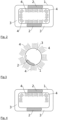
- Figure 1a A first example of the structure of the proposed device is shown in cross section.
- Figure 1a shows a ring-shaped container 1 that forms a closed channel around the central area of the device and is partially filled with a ferrofluid 2.
- the container 1 is filled with the ferrofluid 2 in such a way that two separate partial volumes of the ferrofluid are present, which are separated from each other by a liquid or gaseous medium 3.
- the ring-shaped container 1 encloses a central area in which six coils 4 are arranged with their axes in a star shape, as can be seen from Figure 1a. is visible. Two opposing coils 4 form a coil pair connected to one another.
- the respective open first ends A, B, C of the coil pairs can be energized via a control device (not shown) so that a current flows through the respective coil pairs.
- the second ends are connected to a common ground connection.
- FIG. 1b The generation of the rotating magnetic fields and the resulting movement of the ferrofluid is illustrated using Figures 1b - 1d.
- the ends B and C are first put under voltage by the control device.
- the current flow thus generated in the corresponding coil pairs forms the magnetic fields 5 shown in the figure.
- each of the two partial volumes of the ferrofluid 2 flows in the direction of the respective magnetic field 5, as indicated in the figure by the arrows. Since this process takes place symmetrically, an angular momentum is stored in the system and a torque is exerted. This enables the position control of a spacecraft in which this device is used.
- Figures 1c and 1d show the continuation of this process by applying the voltage to the ends C and A or A and B.
- the magnetic fields 5 and Movements of the ferrofluid 2 are again shown in the figures.
- the control of the individual coil pairs of the device by the control device preferably takes place in such a way that a continuous and uniform rotation of the magnetic fields 5 is obtained.
- the control device preferably generates a sinusoidal multi-phase alternating current, in the present example with three coil pairs a three-phase alternating current.
- the number of electrical coils or coil groups is not limited to the Figure 1
- the number of coils per group is limited to the number shown. Rather, more than two coils per group or more than three groups of coils can be used. Group formation is not always necessary either.
- the individual coils can also be controlled individually and independently of one another. Depending on the distribution of the ferrofluid, this independent control may also be necessary.
- the container 1 is, for example, disk-shaped in a central area of the device, whereby in this example the coils 4 with their coil axes are arranged in a star shape around the container 1.
- the ferrofluid 2 can be moved on a closed path by a rotating magnetic field.
- the coils 4 do not have to be arranged completely around the container 1 or along the closed path. This is for example the case in Figure 4 as a modification of the design of the Figure 3 shown, but can of course also be applied to other configurations, such as the Figure 1 or the Figure 2
- the movement of the ferrofluid 2 in the track area without coils is achieved by momentum transfer within the media 2, 3 in the container 1.
Landscapes
- Engineering & Computer Science (AREA)
- Remote Sensing (AREA)
- Power Engineering (AREA)
- Chemical & Material Sciences (AREA)
- Combustion & Propulsion (AREA)
- Radar, Positioning & Navigation (AREA)
- Aviation & Aerospace Engineering (AREA)
- Automation & Control Theory (AREA)
- Control Of Position, Course, Altitude, Or Attitude Of Moving Bodies (AREA)
- Fluid-Damping Devices (AREA)
Description
- Die vorliegende Erfindung betrifft eine Vorrichtung zur Lageregelung eines Raumfahrzeuges, die ein teilweise mit einem magnetisierbaren Fluid gefülltes Behältnis und eine Einrichtung zur Erzeugung wenigstens eines rotierenden Magnetfeldes aufweist, durch das das magnetisierbare Fluid in dem Behältnis in eine kontinuierliche Bewegung auf einer geschlossenen Bahn versetzt werden kann.
- Beim Betrieb von Raumfahrzeugen ist es häufig erforderlich, eine oder mehrere Vorrichtungen auf dem Raumfahrzeug vorzusehen, mit denen die Lage des Raumfahrzeugs gezielt verändert oder korrigiert werden kann. Dies kann bspw. über ein Antriebssystem des Raumfahrzeugs erfolgen, das durch einen exzentrischen Schub einen Drehimpuls erzeugt. Weiterhin ist es bekannt, Raumfahrzeuge mit mechanischen Drall- und Reaktionsrädern auszustatten. Hierbei wird in einem schnell rotierenden Schwungrad ein Drehimpuls gespeichert und bei Bedarf durch Beschleunigung oder Abbremsung des Schwungrades auf das Raumfahrzeug übertragen. Falls ein externes Magnetfeld wie das der Erde vorliegt, kann durch ein auf dem Raumfahrzeug selbst erzeugtes Magnetfeld ein reaktives Drehmoment generiert werden. Dies wird üblicherweise durch eine bestromte Spule erzeugt.
- Mechanische Drall- und Reaktionsräder sind allerdings sehr teuer in der Herstellung, da sehr hohe Anforderungen an Toleranzen und Rundlaufeigenschaften vorliegen. Derartige mechanische Systeme können zudem leicht versagen und haben nur eine begrenzte Lebenszeit. Für die Erzeugung eines reaktiven Drehmomentes durch ein selbsterzeugtes Magnetfeld ist die Nähe eines Himmelskörpers mit relevantem Magnetfeld erforderlich. Die Effektivität ist hier außerdem von Position und Orbit des Raumfahrzeuges abhängig. Ein Antriebssystem zur Erzeugung des Drehimpulses verbraucht Treibstoff und ist daher nur begrenzt verfügbar. Durch die Treibstoffmasse werden zusätzlich die Startkosten des Raumfahrzeuges erhöht. Eine hochpräzise Lageregelung ist mit einem Antriebssystem oft nur eingeschränkt möglich.
- In M. Ehresmann et al., "PAPELL: Mechanic-free Actuators through Ferrofluids", 12th IAA Symposium on Small Satellites for Earth Oberservation, Berlin, Mai 2019 ist eine Technik zur Erzeugung eines variablen Drehimpulses beschrieben, bei der ein Ferrofluid in einem kreisförmigen Rohr durch zwei Gruppen von jeweils vier Elektromagneten auf einer Kreisbahn bewegt wird. Die Elektromagneten sind hierbei als Topfmagneten ausgebildet, deren Spulenachse senkrecht zu der Bahnebene des bewegten Ferrofluids ausgerichtet sind. Die Magnete werden jeweils in geeigneter zeitlicher Reihenfolge an- und ausgeschaltet, um das Fluid auf der Kreisbahn zu bewegen. Das Ferrofluid wird bei dieser Ausgestaltung allerdings nur jeweils von einem Magneten zum nächsten transportiert und dort dann durch den Magneten wieder abgebremst, so dass kein ausreichend großer Drehimpuls erzeugt werden kann.
- Die
JP H03281496 A - Aus der
CN 104483972 B , derDE 10230350 A1 , derDE 102009036327 A1 und derEP 0131061 A1 sind Vorrichtungen zur Erzeugung eines variablen Drehimpulses bekannt, die eine elektrisch leitfähige Flüssigkeit benötigen und nach dem Prinzip der Induktionspumpe unter Ausnutzung von Lorentzkräften arbeiten. - Die
US 3 906 415 A beschreibt eine Vorrichtung, die elektrische Schaltfunktionen, elektrische Generatorfunktionen, elektrische Motorfunktionen und Pumpfunktionen ausführen soll. Die Vorrichtung umfasst ein Isolierrohr, in dem ein segmentierter Flüssigkeitsstrom aus einer Vielzahl aneinandergrenzender Segmente aus Quecksilber und Ferrofluid durch äußere Magnetfelder bewegt wird, die durch elektrische Spulen erzeugt werden. - Die Aufgabe der vorliegenden Erfindung besteht darin, eine Vorrichtung zur Lageregelung eines Raumfahrzeuges anzugeben, die ohne mechanische Komponenten, externe Magnetfelder oder zusätzlichen Treibstoff auskommt und die Erzeugung und Änderung eines ausreichend großen Drehimpulses oder Drehmomentes ermöglicht.
- Die Aufgabe wird mit der Vorrichtung gemäß Patentanspruch 1 gelöst. Vorteilhafte Ausgestaltungen der Vorrichtung sind Gegenstand der abhängigen Patentansprüche oder lassen sich der nachfolgenden Beschreibung sowie den Ausführungsbeispielen entnehmen.
- Die vorgeschlagene Vorrichtung weist ein nur teilweise mit einem magnetisierbaren Fluid, insbesondere einem Ferrofluid, gefülltes Behältnis und eine Einrichtung zur Erzeugung eines oder mehrerer rotierender oder wandernder Magnetfelder auf, durch die das magnetisierbare Fluid in dem Behältnis in eine kontinuierliche Bewegung auf einer geschlossenen Bahn versetzt werden kann. Das verbleibende Innenvolumen des mit dem magnetisierbaren Fluid nur teilweise gefüllten Behältnisses ist entweder mit einem flüssigen Medium aufgefüllt ist, das eine höhere Dichte als das magnetisierbare Fluid aufweist und sich nicht mit dem magnetisierbaren Fluid mischt, oder das Behältnis ist so mit dem magnetisierbaren Fluid gefüllt, dass mehrere voneinander getrennte Teilvolumina des magnetisierbaren Fluids vorhanden sind. Die Einrichtung zur Erzeugung des einen oder der mehreren rotierenden oder wandernden Magnetfelder weist mehrere elektrische Spulen zur Erzeugung der Magnetfelder auf, deren Spulenachsen in der Bahnebene der geschlossenen Bewegungsbahn des magnetisierbaren Fluids liegen und jeweils senkrecht zu einem nächstkommenden Abschnitt der geschlossenen Bahn ausgerichtet sind. Die Einrichtung zur Erzeugung des einen oder der mehreren rotierenden oder wandernden Magnetfelder umfasst auch eine Steuereinrichtung, über die ein phasenversetzter Stromfluss durch die elektrischen Spulen erzeugt und gesteuert oder geregelt werden kann. Vorzugsweise ist die Steuereinrichtung dabei so ausgebildet, dass sie einen phasenversetzten sinusförmigen Stromfluss durch die Spulen erzeugen kann.
- Durch die Anordnung der elektrischen Spulen lassen sich ein oder mehrere rotierende oder wandernde Magnetfelder erzeugen, durch das bzw. die die magnetisierbare Flüssigkeit im Behältnis magnetisiert und durch die Rotation oder Bewegung des oder der Magnetfelder kontinuierlich auf einer geschlossenen Bahn im Behältnis bewegt wird. Dadurch wird durch diese Flüssigkeit ein Drehimpuls erzeugt, dessen Stärke u.a. von der Bewegungsgeschwindigkeit des magnetisierbaren Fluids auf der geschlossenen Bahn abhängt. Durch Steuerung der Rotations- oder Bewegungsgeschwindigkeit des Magnetfeldes bzw. der Magnetfelder kann diese Bewegungsgeschwindigkeit und damit der Drehimpuls variiert und dadurch ein Drehmoment erzeugt werden. Der in dieser Vorrichtung erzeugte Drehimpuls überträgt dann einen umgekehrten Drehimpuls auf das Raumfahrzeug. Damit kann die Lage und Ausrichtung des Raumfahrzeuges im Raum gesteuert werden.
- In einer vorteilhaften Ausgestaltung erstreckt sich das Behältnis um einen zentralen Bereich der Vorrichtung, wobei die elektrischen Spulen in dem zentralen Bereich angeordnet sind. Das Behältnis bildet hierbei vorzugsweise einen umlaufenden Kanal um den zentralen Bereich, bspw. einen ringförmigen oder ellipsenförmigen Kanal. Der Kanalquerschnitt kann dabei eine beliebige Form aufweisen, bspw. rechteckig oder kreisförmig.
- In einer anderen Ausgestaltung befindet sich das Behältnis in dem zentralen Bereich und die Spulen sind um das Behältnis herum angeordnet. In beiden Fällen sind die Spulenachsen jeweils senkrecht zum nächstkommenden Abschnitt der geschlossenen Bahn ausgerichtet, auf der sich das magnetisierbare Fluid bewegen soll. Im Falle eines Behältnisses, das einen ringförmigen Kanal um den zentralen Bereich bildet, sind die Spulenachsen daher sternförmig im zentralen Bereich angeordnet.
- In einer weiteren Ausgestaltung befindet ist nur ein Teil des Behältnisses von Spulen zur aktiven Bewegung von Ferrofluid umgeben. An anderen Abschnitten des Behältnisses befinden sich keine Spulen oder Spulenpaare. Die Bewegung hier wird nur durch Impulsübertrag innerhalb der Medien bzw. Flüssigkeiten erreicht.
- Das durch die nur teilweise Füllung mit dem magnetisierbaren Fluid verbleibende Innenvolumen des Behältnisses ist in einer Alternative der vorgeschlagenen Vorrichtung mit einem flüssigen Medium aufgefüllt, das eine höhere Dichte als das magnetisierbare Fluid aufweist und sich nicht mit diesem mischt. Dieses flüssige Medium wird durch die Bewegung des magnetisierbaren Fluids ebenfalls auf der geschlossenen Bahn bewegt und erhöht dadurch den Drehimpuls. Vorzugsweise wird hierbei als flüssiges Medium ein bei Raumtemperatur (20° C) flüssiges metallisches Material mit einer Dichte von ≥ 6 g·cm-3 verwendet. Besonders vorteilhaft lässt sich hierbei Quecksilber oder eine als Galinstan bekannte eutektische Legierung aus Gallium und Indium oder aus Gallium, Indium und Zinn einsetzen. Als magnetisierbares Fluid wird vorzugsweise ein Ferrofluid eingesetzt.
- In einer anderen Alternative der vorgeschlagenen Vorrichtung ist das Behältnis so mit dem magnetisierbaren Fluid gefüllt, dass mehrere durch ein flüssiges oder gasförmiges Medium voneinander getrennte Teilvolumina des magnetisierbaren Fluids vorhanden sind, die getrennt voneinander auf der geschlossenen Bahn umlaufen. Die Steuerung der Einrichtung zur Erzeugung eines oder mehrerer rotierender oder wandernder Magnetfelder ist dabei vorzugsweise so angepasst, dass alle diese Teilvolumina durch Magnetfelder entsprechend angetrieben werden.
- Die einzelnen Spulen können geeignete Kernmaterialien zur Erhöhung der magnetischen Feldstärken, wie bspw. Eisenkerne, aufweisen. Weiterhin kann die Vorrichtung auch einen magnetischen Schild zur Abschirmung des Außenbereichs von den erzeugten Magnetfeldern aufweisen. Mit der vorgeschlagenen Vorrichtung wird durch die magnetische Bewegung der magnetisierbaren Flüssigkeit auf einer geschlossenen Bahn ein Drehimpuls gespeichert. Durch gezielte Änderung der Flüssigkeitsgeschwindigkeit über die Einrichtung zur Erzeugung des einen oder der mehreren rotierenden oder wandernden Magnetfelder wird der gespeicherte Drehimpuls geändert und damit auch der auf das Raumfahrzeug übertragene Drehimpuls. Auch eine Umkehrung des Drehimpulses um 180° durch Umkehrung der Rotations- oder Bewegungsrichtung des Magnetfeldes bzw. der Magnetfelder ist möglich. Damit können mit der vorgeschlagenen Vorrichtung Lageregelungsaufgaben eines Raumfahrzeuges ohne mechanische Komponenten oder externe Magnetfelder auf einfache, zuverlässige und kostengünstige Art und Weise realisiert werden. Die Vorrichtung erfordert keine mechanisch bewegten Komponenten und hat daher im Vergleich zu mechanischen Lösungen einen deutlich geringeren Verschleiß und eine höhere Lebenszeit und Zuverlässigkeit.
- Die vorgeschlagene Vorrichtung wird nachfolgend anhand von Ausführungsbeispielen in Verbindung mit den Zeichnungen nochmals beispielhaft näher erläutert. Hierbei zeigen:
- Fig. 1
- einen beispielhaften Aufbau der vorgeschlagenen Vorrichtung sowie drei Phasen der Bewegung des magnetisierbaren Fluids;
- Fig. 2
- in schematischer Darstellung ein weiteres Beispiel für einen Aufbau der vorgeschlagenen Vorrichtung;
- Fig. 3
- in schematischer Darstellung ein weiteres Beispiel für einen Aufbau der vorgeschlagenen Vorrichtung; und
- Fig. 4
- in schematischer Darstellung ein weiteres Beispiel für einen Aufbau der vorgeschlagenen Vorrichtung.
- Das Prinzip der vorgeschlagenen Vorrichtung beruht darauf, dass eine magnetisierbare Flüssigkeit durch lokal ausreichend starke magnetische Felder magnetisiert und durch diese Magnetfelder angezogen wird. Durch gezielte Verschiebung der Positionen hoher Magnetfeldstärke kann die magnetisierte Flüssigkeit entsprechend bewegt werden. Bei der vorgeschlagenen Vorrichtung werden nun ein oder mehrere rotierende oder wandernde Magnetfelder genutzt, um die magnetisierbare Flüssigkeit in eine kontinuierliche Bewegung auf einer geschlossenen Bahn zu versetzen und dadurch einen Drehimpuls zu erzeugen. Dies wird durch geeignete Anordnung und Ansteuerung elektrischer Spulen erreicht, deren Spulenachsen in der Bahnebene liegen.
- In
Figur 1 ist im Querschnitt ein erstes Beispiel für den Aufbau der vorgeschlagenen Vorrichtung dargestellt. Figur 1a zeigt hierbei ein ringförmig ausgeführtes Behältnis 1, das einen geschlossenen Kanal um den zentralen Bereich der Vorrichtung bildet und mit einem Ferrofluid 2 teilweise gefüllt ist. In diesem Beispiel ist das Behältnis 1 so mit dem Ferrofluid 2 gefüllt, dass zwei voneinander getrennte Teilvolumina des Ferrofluids vorliegen, die durch ein flüssiges oder gasförmiges Medium 3 voneinander getrennt sind. Das ringförmige Behältnis 1 umschließt einen zentralen Bereich, in dem sechs Spulen 4 mit ihren Achsen sternförmig angeordnet sind, wie dies aus der Figur 1a ersichtlich ist. Jeweils zwei gegenüberliegende Spulen 4 bilden ein miteinander verbundenes Spulenpaar. Die jeweiligen offenen ersten Enden A, B, C der Spulenpaare können über eine nicht dargestellte Steuereinrichtung unter Spannung gesetzt werden, so dass ein Strom durch die jeweiligen Spulenpaare fließt. Die zweiten Enden sind dabei mit einem gemeinsamen Masseanschluss verbunden. Durch geeignete phasenversetzte Ansteuerung der einzelnen Spulenpaare mittels der Steuereinrichtung lassen sich zwei rotierende Magnetfelder 5 erzeugen, durch die jedes der beiden Teilvolumina des Ferrofluids 2 auf einer durch das Behältnis 1 vorgegebenen ringförmigen Bahn bewegt wird. Die Spulenachsen der Spulen 4 liegen hierbei alle innerhalb der Bahnebene dieser Bahn. - Die Erzeugung der rotierenden Magnetfelder und daraus resultierende Bewegung des Ferrofluids wird anhand der Figuren 1b - 1d veranschaulicht. So werden in Figur 1b zunächst die Enden B und C durch die Steuereinrichtung unter Spannung gesetzt. Durch den damit erzeugten Stromfluss in den entsprechenden Spulenpaaren bilden sich die in der Figur dargestellten Magnetfelder 5 aus. Dadurch fließt jedes der beiden Teilvolumina des Ferrofluids 2 in Richtung des jeweiligen Magnetfelds 5, wie dies in der Figur durch die Pfeile angedeutet ist. Da dieser Prozess symmetrisch stattfindet, wird ein Drehimpuls im System gespeichert und ein Drehmoment ausgeübt. Damit wird eine Lageregelung eines Raumfahrzeugs realisiert, in dem diese Vorrichtung eingesetzt wird. Die Figuren 1c und 1d zeigen die Fortsetzung dieses Vorgangs durch Anlegen der Spannung an die Enden C und A bzw. A und B. Die jeweils dadurch erzeugten Magnetfelder 5 und Bewegungen des Ferrofluids 2 sind wiederum in den Figuren dargestellt. Die Ansteuerung der einzelnen Spulenpaare der Vorrichtung durch die Steuereinrichtung erfolgt dabei vorzugsweise derart, dass eine kontinuierliche und gleichmäßige Rotation der Magnetfelder 5 erhalten wird. Hierzu wird durch die Steuereinrichtung vorzugsweise ein sinusförmiger Mehrphasenwechselstrom, im vorliegenden Beispiel mit drei Spulenpaaren ein Dreiphasenwechselstrom, erzeugt.
- Die Anzahl der elektrischen Spulen bzw. Spulengruppen ist nicht auf die in
Figur 1 dargestellte Menge beschränkt. Vielmehr können auch mehr als zwei Spulen pro Gruppe oder auch mehr als drei Gruppen von Spulen eingesetzt werden. Auch eine Gruppenbildung ist nicht in jedem Falle erforderlich. Die einzelnen Spulen können auch einzeln unabhängig voneinander angesteuert werden. Je nach Aufteilung des Ferrofluids kann diese unabhängige Ansteuerung auch erforderlich sein. Weiterhin ist es selbstverständlich auch möglich, das Behältnis 1 nicht ringförmig sondern in einer anderen Form auszugestalten, wie dies beispielhaft schematisch inFigur 2 angedeutet ist. In dieser Figur bildet das Behältnis 1 wiederum einen Kanal um einen zentralen Bereich, in dem die einzelnen Spulen 4 geeignet zur Erzeugung von zwei rotierenden Magnetfeldern angeordnet sind. - Auch eine Anordnung der Spulen 4 um das Behältnis 1 herum ist möglich, wie dies schematisch anhand eines Beispiels in
Figur 3 angedeutet ist. Das Behältnis 1 ist in diesem Falle bspw. scheibenförmig in einem zentralen Bereich der Vorrichtung ausgebildet, wobei in diesem Beispiel die Spulen 4 mit ihren Spulenachsen sternförmig um das Behältnis 1 herum angeordnet sind. Auch in diesem Beispiel lässt sich das Ferrofluid 2 durch ein rotierendes Magnetfeld auf einer geschlossenen Bahn bewegen. - Die Spulen 4 müssen nicht vollständig um das Behältnis 1 herum bzw. entlang der geschlossenen Bahn angeordnet sein. Dies ist bespielhaft in
Figur 4 als Modifikation der Ausgestaltung derFigur 3 dargestellt, lässt sich aber natürlich auch auf andere Ausgestaltungen, wie bspw. die derFigur 1 oder derFigur 2 , übertragen. Die Bewegung des Ferrofluids 2 im Bahnbereich ohne Spulen erfolgt dabei durch Impulsübertrag innerhalb der Medien 2, 3 im Behältnis 1. -
- 1
- Behältnis
- 2
- Ferrofluid
- 3
- flüssiges oder gasförmiges Medium
- 4
- Spule
- 5
- Magnetfeld
- A, B, C
- Enden der Spulen
Claims (7)
- Vorrichtung zur Lageregelung eines Raumfahrzeuges, die- ein teilweise mit einem magnetisierbaren Fluid (2) gefülltes Behältnis (1) und- eine Einrichtung zur Erzeugung wenigstens eines rotierenden oder wandernden Magnetfeldes aufweist, durch das das magnetisierbare Fluid (2) in dem Behältnis (1) magnetisiert und durch die Rotation oder Bewegung des wenigstens einen Magnetfeldes in eine kontinuierliche Bewegung auf einer geschlossenen Bahn in einer Bahnebene versetzt werden kann,wobei die Einrichtung zur Erzeugung wenigstens eines rotierenden oder wandernden Magnetfeldes mehrere elektrische Spulen (4) zur Erzeugung des Magnetfeldes, deren Spulenachsen in der Bahnebene liegen und jeweils senkrecht zu einem nächstkommenden Abschnitt der geschlossenen Bahn ausgerichtet sind, undeine Steuereinrichtung aufweist, über die ein phasenversetzter Stromfluss durch die elektrischen Spulen (4) erzeugt und gesteuert oder geregelt werden kann,dadurch gekennzeichnet,dass entweder ein durch die teilweise Füllung mit dem magnetisierbaren Fluid (2) verbleibendes Innenvolumen des Behältnisses (1) mit einem flüssigen Medium aufgefüllt ist, das eine höhere Dichte als das magnetisierbare Fluid (2) aufweist und sich nicht mit dem magnetisierbaren Fluid (2) mischt, oder das Behältnis (1) so mit dem magnetisierbaren Fluid (2) gefüllt ist, dass mehrere voneinander getrennte Teilvolumina des magnetisierbaren Fluids (2) vorhanden sind.
- Vorrichtung nach Anspruch 1,
dadurch gekennzeichnet,
dass sich das Behältnis (1) um einen zentralen Bereich der Vorrichtung erstreckt und die elektrischen Spulen (4) in dem zentralen Bereich angeordnet sind. - Vorrichtung nach Anspruch 1,
dadurch gekennzeichnet,
dass die elektrischen Spulen (4) um das Behältnis (1) herum angeordnet sind. - Vorrichtung nach Anspruch 2,
dadurch gekennzeichnet,
dass das Behältnis (1) einen geschlossenen Kanal um den zentralen Bereich bildet. - Vorrichtung nach Anspruch 4,
dadurch gekennzeichnet,
dass das Behältnis (1) ringförmig um den zentralen Bereich ausgebildet ist. - Vorrichtung nach einem der Ansprüche 1 bis 5, dadurch gekennzeichnet,
dass das flüssige Medium ein bei Raumtemperatur flüssiges metallisches Material mit einer Dichte von ≥ 6 g·cm-3 ist, insbesondere Quecksilber oder eine eutektische Legierung aus Gallium und Indium oder aus Gallium, Indium und Zinn. - Vorrichtung nach einem der Ansprüche 1 bis 6, dadurch gekennzeichnet,
dass die Steuereinrichtung so ausgebildet ist, dass sie einen phasenversetzten sinusförmigen Stromfluss durch die Spulen (4) erzeugen kann.
Priority Applications (2)
| Application Number | Priority Date | Filing Date | Title |
|---|---|---|---|
| EP20171813.7A EP3904220B1 (de) | 2020-04-28 | 2020-04-28 | Vorrichtung zur lageregelung von raumfahrzeugen |
| US17/242,359 US20210331816A1 (en) | 2020-04-28 | 2021-04-28 | Device for generating a variable angular momentum, in particular for spacecraft attitude control |
Applications Claiming Priority (1)
| Application Number | Priority Date | Filing Date | Title |
|---|---|---|---|
| EP20171813.7A EP3904220B1 (de) | 2020-04-28 | 2020-04-28 | Vorrichtung zur lageregelung von raumfahrzeugen |
Publications (2)
| Publication Number | Publication Date |
|---|---|
| EP3904220A1 EP3904220A1 (de) | 2021-11-03 |
| EP3904220B1 true EP3904220B1 (de) | 2024-08-14 |
Family
ID=70476013
Family Applications (1)
| Application Number | Title | Priority Date | Filing Date |
|---|---|---|---|
| EP20171813.7A Active EP3904220B1 (de) | 2020-04-28 | 2020-04-28 | Vorrichtung zur lageregelung von raumfahrzeugen |
Country Status (2)
| Country | Link |
|---|---|
| US (1) | US20210331816A1 (de) |
| EP (1) | EP3904220B1 (de) |
Cited By (2)
| Publication number | Priority date | Publication date | Assignee | Title |
|---|---|---|---|---|
| EP4704123A1 (de) * | 2024-08-27 | 2026-03-04 | Universität Stuttgart Körperschaft des Öffentlichen Rechts | Vorrichtung und verfahren zur erzeugung und steuerung von magnetfeldern |
| EP4722552A1 (de) | 2024-10-07 | 2026-04-08 | Universität Stuttgart | Vorrichtung zur erzeugung eines variablen drehimpulses, insbesondere zur lageregelung von raumfahrzeugen |
Families Citing this family (1)
| Publication number | Priority date | Publication date | Assignee | Title |
|---|---|---|---|---|
| CN116236960A (zh) * | 2023-03-13 | 2023-06-09 | 张春节 | 一种磁性混合液控制装置 |
Citations (1)
| Publication number | Priority date | Publication date | Assignee | Title |
|---|---|---|---|---|
| US3906415A (en) * | 1974-06-14 | 1975-09-16 | Massachusetts Inst Technology | Apparatus wherein a segmented fluid stream performs electrical switching functions and the like |
Family Cites Families (12)
| Publication number | Priority date | Publication date | Assignee | Title |
|---|---|---|---|---|
| US2856142A (en) * | 1956-07-18 | 1958-10-14 | Gen Electric | Orientation control for a space vehicle |
| US3574485A (en) * | 1958-11-28 | 1971-04-13 | Broido Louis | Method and apparatus for movement of liquids by electromagnetic means |
| GB2070244B (en) * | 1980-01-23 | 1984-02-29 | Furuno Electric Co | Gyroscopic instrument |
| ATE26635T1 (de) * | 1983-07-08 | 1987-05-15 | Nitrokemia Ipartelepek | Lineare induktionspumpe zum foerdern von elektrisch leitfaehigen fluessigkeiten. |
| US5026008A (en) * | 1990-01-31 | 1991-06-25 | The United States Of America As Represented By The Administrator Of The National Aeronautics And Space Administration | Fluid-loop reaction system |
| JP3000612B2 (ja) * | 1990-03-29 | 2000-01-17 | 日本電気株式会社 | 宇宙機姿勢制御用電磁リング |
| DE10230350B4 (de) * | 2002-06-28 | 2005-09-29 | Technische Universität Dresden | Raumfahrzeug mit einer Einrichtung zur Lageregelung |
| DE102009036327A1 (de) * | 2009-08-05 | 2011-02-10 | Daniel Noack | Fluiddynamischer Aktuator |
| KR101245196B1 (ko) * | 2011-01-25 | 2013-03-19 | 주식회사 아앤시티 | 자이로스코프 |
| DE102011105862A1 (de) * | 2011-06-23 | 2012-12-27 | Daniel Noack | Fluiddynamischer Aktuator |
| CN104483972B (zh) * | 2014-10-31 | 2017-04-12 | 上海新跃仪表厂 | 一种航天器流体环反作用执行机构 |
| CA3030308C (en) * | 2016-07-29 | 2022-04-05 | The Board Of Trustees Of Western Michigan University | Magnetic nanoparticle-based gyroscopic sensor |
-
2020
- 2020-04-28 EP EP20171813.7A patent/EP3904220B1/de active Active
-
2021
- 2021-04-28 US US17/242,359 patent/US20210331816A1/en not_active Abandoned
Patent Citations (1)
| Publication number | Priority date | Publication date | Assignee | Title |
|---|---|---|---|---|
| US3906415A (en) * | 1974-06-14 | 1975-09-16 | Massachusetts Inst Technology | Apparatus wherein a segmented fluid stream performs electrical switching functions and the like |
Cited By (2)
| Publication number | Priority date | Publication date | Assignee | Title |
|---|---|---|---|---|
| EP4704123A1 (de) * | 2024-08-27 | 2026-03-04 | Universität Stuttgart Körperschaft des Öffentlichen Rechts | Vorrichtung und verfahren zur erzeugung und steuerung von magnetfeldern |
| EP4722552A1 (de) | 2024-10-07 | 2026-04-08 | Universität Stuttgart | Vorrichtung zur erzeugung eines variablen drehimpulses, insbesondere zur lageregelung von raumfahrzeugen |
Also Published As
| Publication number | Publication date |
|---|---|
| EP3904220A1 (de) | 2021-11-03 |
| US20210331816A1 (en) | 2021-10-28 |
Similar Documents
| Publication | Publication Date | Title |
|---|---|---|
| DE69304517T2 (de) | Elektrische stromerzeuger | |
| DE69503336T2 (de) | Linearantrieb | |
| CH625366A5 (de) | ||
| EP3904220A1 (de) | Vorrichtung zur erzeugung eines variablen drehimpulses, insbesondere zur lageregelung von raumfahrzeugen | |
| DE3927454C2 (de) | ||
| WO2019001623A1 (de) | Permanentmagnet-erregter motor mit verdrehbaren magnetstäben | |
| WO2016096830A1 (de) | Elektrische maschine, stator für eine elektrische maschine und fahrzeug | |
| DE10036526A1 (de) | Zentrierbares Magnetlager mit Kippsteuerung mit großer Amplitude | |
| CH646553A5 (en) | Homopolar machine | |
| DE3402768C2 (de) | Bistabiles magnetisches Stellglied | |
| EP3351670B1 (de) | Flechtmaschine mit magnetischen flügelrädern | |
| DE19848551A1 (de) | Antrieb für das bewegliche Kontaktstück eines elektrischen Schalters | |
| DE4204070C1 (de) | ||
| DE102018212764A1 (de) | Supraleitender Magnet, Verfahren zu dessen Herstellung, elektrische Maschine und hybridelektrisches Luftfahrzeug | |
| EP1405388B1 (de) | Geschalteter reluktanzmotor mit radialem und transversalem fluss | |
| DE19530341A1 (de) | Elektrodynamischer Zweikoordinatenantrieb | |
| DE102015210032A1 (de) | Mehrphasige Transversalflussmaschine | |
| DE102022115076A1 (de) | Stellvorrichtung für ein Fahrzeug und Verfahren zum Betreiben einer Stellvorrichtung | |
| DE102022115077A1 (de) | Stellvorrichtung für ein Fahrzeug und Verfahren zum Betreiben einer Stellvorrichtung | |
| EP4722552A1 (de) | Vorrichtung zur erzeugung eines variablen drehimpulses, insbesondere zur lageregelung von raumfahrzeugen | |
| DE102005008812A1 (de) | Nicht rotierender Linearaktuator | |
| DE102019202760A1 (de) | Dichtmanschette für einen Stator einer elektrischen Maschine | |
| DE102022115083A1 (de) | Stellvorrichtung für ein Fahrzeug und Verfahren zum Betreiben einer Stellvorrichtung | |
| DE102006062532A1 (de) | Elektromotor | |
| WO2017198496A1 (de) | Elektrische maschine mit doppelläuferanordnung mit kryogenem ferromagnetikum |
Legal Events
| Date | Code | Title | Description |
|---|---|---|---|
| PUAI | Public reference made under article 153(3) epc to a published international application that has entered the european phase |
Free format text: ORIGINAL CODE: 0009012 |
|
| STAA | Information on the status of an ep patent application or granted ep patent |
Free format text: STATUS: THE APPLICATION HAS BEEN PUBLISHED |
|
| AK | Designated contracting states |
Kind code of ref document: A1 Designated state(s): AL AT BE BG CH CY CZ DE DK EE ES FI FR GB GR HR HU IE IS IT LI LT LU LV MC MK MT NL NO PL PT RO RS SE SI SK SM TR |
|
| B565 | Issuance of search results under rule 164(2) epc |
Effective date: 20201020 |
|
| STAA | Information on the status of an ep patent application or granted ep patent |
Free format text: STATUS: REQUEST FOR EXAMINATION WAS MADE |
|
| 17P | Request for examination filed |
Effective date: 20220331 |
|
| RBV | Designated contracting states (corrected) |
Designated state(s): AL AT BE BG CH CY CZ DE DK EE ES FI FR GB GR HR HU IE IS IT LI LT LU LV MC MK MT NL NO PL PT RO RS SE SI SK SM TR |
|
| STAA | Information on the status of an ep patent application or granted ep patent |
Free format text: STATUS: EXAMINATION IS IN PROGRESS |
|
| 17Q | First examination report despatched |
Effective date: 20230123 |
|
| REG | Reference to a national code |
Ref country code: DE Ref legal event code: R079 Free format text: PREVIOUS MAIN CLASS: B64G0001240000 Ipc: H02K0007140000 Ref country code: DE Ref legal event code: R079 Ref document number: 502020008846 Country of ref document: DE Free format text: PREVIOUS MAIN CLASS: B64G0001240000 Ipc: H02K0007140000 |
|
| GRAP | Despatch of communication of intention to grant a patent |
Free format text: ORIGINAL CODE: EPIDOSNIGR1 |
|
| STAA | Information on the status of an ep patent application or granted ep patent |
Free format text: STATUS: GRANT OF PATENT IS INTENDED |
|
| RIC1 | Information provided on ipc code assigned before grant |
Ipc: H02K 7/00 20060101ALI20240226BHEP Ipc: H02K 44/00 20060101ALI20240226BHEP Ipc: B64G 1/24 20060101ALI20240226BHEP Ipc: H02K 1/02 20060101ALI20240226BHEP Ipc: H02K 7/14 20060101AFI20240226BHEP |
|
| INTG | Intention to grant announced |
Effective date: 20240312 |
|
| GRAS | Grant fee paid |
Free format text: ORIGINAL CODE: EPIDOSNIGR3 |
|
| GRAA | (expected) grant |
Free format text: ORIGINAL CODE: 0009210 |
|
| STAA | Information on the status of an ep patent application or granted ep patent |
Free format text: STATUS: THE PATENT HAS BEEN GRANTED |
|
| AK | Designated contracting states |
Kind code of ref document: B1 Designated state(s): AL AT BE BG CH CY CZ DE DK EE ES FI FR GB GR HR HU IE IS IT LI LT LU LV MC MK MT NL NO PL PT RO RS SE SI SK SM TR |
|
| REG | Reference to a national code |
Ref country code: GB Ref legal event code: FG4D Free format text: NOT ENGLISH |
|
| REG | Reference to a national code |
Ref country code: CH Ref legal event code: EP |
|
| REG | Reference to a national code |
Ref country code: DE Ref legal event code: R096 Ref document number: 502020008846 Country of ref document: DE |
|
| REG | Reference to a national code |
Ref country code: IE Ref legal event code: FG4D Free format text: LANGUAGE OF EP DOCUMENT: GERMAN |
|
| REG | Reference to a national code |
Ref country code: LT Ref legal event code: MG9D |
|
| REG | Reference to a national code |
Ref country code: NL Ref legal event code: MP Effective date: 20240814 |
|
| PG25 | Lapsed in a contracting state [announced via postgrant information from national office to epo] |
Ref country code: NL Free format text: LAPSE BECAUSE OF FAILURE TO SUBMIT A TRANSLATION OF THE DESCRIPTION OR TO PAY THE FEE WITHIN THE PRESCRIBED TIME-LIMIT Effective date: 20240814 Ref country code: PT Free format text: LAPSE BECAUSE OF FAILURE TO SUBMIT A TRANSLATION OF THE DESCRIPTION OR TO PAY THE FEE WITHIN THE PRESCRIBED TIME-LIMIT Effective date: 20241216 Ref country code: GR Free format text: LAPSE BECAUSE OF FAILURE TO SUBMIT A TRANSLATION OF THE DESCRIPTION OR TO PAY THE FEE WITHIN THE PRESCRIBED TIME-LIMIT Effective date: 20241115 Ref country code: PL Free format text: LAPSE BECAUSE OF FAILURE TO SUBMIT A TRANSLATION OF THE DESCRIPTION OR TO PAY THE FEE WITHIN THE PRESCRIBED TIME-LIMIT Effective date: 20240814 Ref country code: FI Free format text: LAPSE BECAUSE OF FAILURE TO SUBMIT A TRANSLATION OF THE DESCRIPTION OR TO PAY THE FEE WITHIN THE PRESCRIBED TIME-LIMIT Effective date: 20240814 |
|
| PG25 | Lapsed in a contracting state [announced via postgrant information from national office to epo] |
Ref country code: BG Free format text: LAPSE BECAUSE OF FAILURE TO SUBMIT A TRANSLATION OF THE DESCRIPTION OR TO PAY THE FEE WITHIN THE PRESCRIBED TIME-LIMIT Effective date: 20240814 |
|
| PG25 | Lapsed in a contracting state [announced via postgrant information from national office to epo] |
Ref country code: LV Free format text: LAPSE BECAUSE OF FAILURE TO SUBMIT A TRANSLATION OF THE DESCRIPTION OR TO PAY THE FEE WITHIN THE PRESCRIBED TIME-LIMIT Effective date: 20240814 |
|
| PG25 | Lapsed in a contracting state [announced via postgrant information from national office to epo] |
Ref country code: IS Free format text: LAPSE BECAUSE OF FAILURE TO SUBMIT A TRANSLATION OF THE DESCRIPTION OR TO PAY THE FEE WITHIN THE PRESCRIBED TIME-LIMIT Effective date: 20241214 |
|
| PG25 | Lapsed in a contracting state [announced via postgrant information from national office to epo] |
Ref country code: HR Free format text: LAPSE BECAUSE OF FAILURE TO SUBMIT A TRANSLATION OF THE DESCRIPTION OR TO PAY THE FEE WITHIN THE PRESCRIBED TIME-LIMIT Effective date: 20240814 |
|
| PG25 | Lapsed in a contracting state [announced via postgrant information from national office to epo] |
Ref country code: ES Free format text: LAPSE BECAUSE OF FAILURE TO SUBMIT A TRANSLATION OF THE DESCRIPTION OR TO PAY THE FEE WITHIN THE PRESCRIBED TIME-LIMIT Effective date: 20240814 Ref country code: RS Free format text: LAPSE BECAUSE OF FAILURE TO SUBMIT A TRANSLATION OF THE DESCRIPTION OR TO PAY THE FEE WITHIN THE PRESCRIBED TIME-LIMIT Effective date: 20241114 |
|
| PG25 | Lapsed in a contracting state [announced via postgrant information from national office to epo] |
Ref country code: RS Free format text: LAPSE BECAUSE OF FAILURE TO SUBMIT A TRANSLATION OF THE DESCRIPTION OR TO PAY THE FEE WITHIN THE PRESCRIBED TIME-LIMIT Effective date: 20241114 Ref country code: PT Free format text: LAPSE BECAUSE OF FAILURE TO SUBMIT A TRANSLATION OF THE DESCRIPTION OR TO PAY THE FEE WITHIN THE PRESCRIBED TIME-LIMIT Effective date: 20241216 Ref country code: PL Free format text: LAPSE BECAUSE OF FAILURE TO SUBMIT A TRANSLATION OF THE DESCRIPTION OR TO PAY THE FEE WITHIN THE PRESCRIBED TIME-LIMIT Effective date: 20240814 Ref country code: NL Free format text: LAPSE BECAUSE OF FAILURE TO SUBMIT A TRANSLATION OF THE DESCRIPTION OR TO PAY THE FEE WITHIN THE PRESCRIBED TIME-LIMIT Effective date: 20240814 Ref country code: LV Free format text: LAPSE BECAUSE OF FAILURE TO SUBMIT A TRANSLATION OF THE DESCRIPTION OR TO PAY THE FEE WITHIN THE PRESCRIBED TIME-LIMIT Effective date: 20240814 Ref country code: IS Free format text: LAPSE BECAUSE OF FAILURE TO SUBMIT A TRANSLATION OF THE DESCRIPTION OR TO PAY THE FEE WITHIN THE PRESCRIBED TIME-LIMIT Effective date: 20241214 Ref country code: HR Free format text: LAPSE BECAUSE OF FAILURE TO SUBMIT A TRANSLATION OF THE DESCRIPTION OR TO PAY THE FEE WITHIN THE PRESCRIBED TIME-LIMIT Effective date: 20240814 Ref country code: GR Free format text: LAPSE BECAUSE OF FAILURE TO SUBMIT A TRANSLATION OF THE DESCRIPTION OR TO PAY THE FEE WITHIN THE PRESCRIBED TIME-LIMIT Effective date: 20241115 Ref country code: FI Free format text: LAPSE BECAUSE OF FAILURE TO SUBMIT A TRANSLATION OF THE DESCRIPTION OR TO PAY THE FEE WITHIN THE PRESCRIBED TIME-LIMIT Effective date: 20240814 Ref country code: ES Free format text: LAPSE BECAUSE OF FAILURE TO SUBMIT A TRANSLATION OF THE DESCRIPTION OR TO PAY THE FEE WITHIN THE PRESCRIBED TIME-LIMIT Effective date: 20240814 Ref country code: BG Free format text: LAPSE BECAUSE OF FAILURE TO SUBMIT A TRANSLATION OF THE DESCRIPTION OR TO PAY THE FEE WITHIN THE PRESCRIBED TIME-LIMIT Effective date: 20240814 |
|
| PG25 | Lapsed in a contracting state [announced via postgrant information from national office to epo] |
Ref country code: RO Free format text: LAPSE BECAUSE OF FAILURE TO SUBMIT A TRANSLATION OF THE DESCRIPTION OR TO PAY THE FEE WITHIN THE PRESCRIBED TIME-LIMIT Effective date: 20240814 Ref country code: SM Free format text: LAPSE BECAUSE OF FAILURE TO SUBMIT A TRANSLATION OF THE DESCRIPTION OR TO PAY THE FEE WITHIN THE PRESCRIBED TIME-LIMIT Effective date: 20240814 Ref country code: DK Free format text: LAPSE BECAUSE OF FAILURE TO SUBMIT A TRANSLATION OF THE DESCRIPTION OR TO PAY THE FEE WITHIN THE PRESCRIBED TIME-LIMIT Effective date: 20240814 |
|
| PG25 | Lapsed in a contracting state [announced via postgrant information from national office to epo] |
Ref country code: EE Free format text: LAPSE BECAUSE OF FAILURE TO SUBMIT A TRANSLATION OF THE DESCRIPTION OR TO PAY THE FEE WITHIN THE PRESCRIBED TIME-LIMIT Effective date: 20240814 |
|
| PG25 | Lapsed in a contracting state [announced via postgrant information from national office to epo] |
Ref country code: CZ Free format text: LAPSE BECAUSE OF FAILURE TO SUBMIT A TRANSLATION OF THE DESCRIPTION OR TO PAY THE FEE WITHIN THE PRESCRIBED TIME-LIMIT Effective date: 20240814 |
|
| PG25 | Lapsed in a contracting state [announced via postgrant information from national office to epo] |
Ref country code: IT Free format text: LAPSE BECAUSE OF FAILURE TO SUBMIT A TRANSLATION OF THE DESCRIPTION OR TO PAY THE FEE WITHIN THE PRESCRIBED TIME-LIMIT Effective date: 20240814 Ref country code: SK Free format text: LAPSE BECAUSE OF FAILURE TO SUBMIT A TRANSLATION OF THE DESCRIPTION OR TO PAY THE FEE WITHIN THE PRESCRIBED TIME-LIMIT Effective date: 20240814 |
|
| REG | Reference to a national code |
Ref country code: DE Ref legal event code: R097 Ref document number: 502020008846 Country of ref document: DE |
|
| PLBE | No opposition filed within time limit |
Free format text: ORIGINAL CODE: 0009261 |
|
| STAA | Information on the status of an ep patent application or granted ep patent |
Free format text: STATUS: NO OPPOSITION FILED WITHIN TIME LIMIT |
|
| 26N | No opposition filed |
Effective date: 20250515 |
|
| PG25 | Lapsed in a contracting state [announced via postgrant information from national office to epo] |
Ref country code: SE Free format text: LAPSE BECAUSE OF FAILURE TO SUBMIT A TRANSLATION OF THE DESCRIPTION OR TO PAY THE FEE WITHIN THE PRESCRIBED TIME-LIMIT Effective date: 20240814 |
|
| REG | Reference to a national code |
Ref country code: DE Ref legal event code: R119 Ref document number: 502020008846 Country of ref document: DE |
|
| REG | Reference to a national code |
Ref country code: CH Ref legal event code: H13 Free format text: ST27 STATUS EVENT CODE: U-0-0-H10-H13 (AS PROVIDED BY THE NATIONAL OFFICE) Effective date: 20251125 |
|
| PG25 | Lapsed in a contracting state [announced via postgrant information from national office to epo] |
Ref country code: LU Free format text: LAPSE BECAUSE OF NON-PAYMENT OF DUE FEES Effective date: 20250428 |
|
| PG25 | Lapsed in a contracting state [announced via postgrant information from national office to epo] |
Ref country code: MC Free format text: LAPSE BECAUSE OF FAILURE TO SUBMIT A TRANSLATION OF THE DESCRIPTION OR TO PAY THE FEE WITHIN THE PRESCRIBED TIME-LIMIT Effective date: 20240814 |
|
| REG | Reference to a national code |
Ref country code: BE Ref legal event code: MM Effective date: 20250430 |
|
| PG25 | Lapsed in a contracting state [announced via postgrant information from national office to epo] |
Ref country code: DE Free format text: LAPSE BECAUSE OF NON-PAYMENT OF DUE FEES Effective date: 20251104 |
|
| PG25 | Lapsed in a contracting state [announced via postgrant information from national office to epo] |
Ref country code: BE Free format text: LAPSE BECAUSE OF NON-PAYMENT OF DUE FEES Effective date: 20250430 |
|
| PG25 | Lapsed in a contracting state [announced via postgrant information from national office to epo] |
Ref country code: CH Free format text: LAPSE BECAUSE OF NON-PAYMENT OF DUE FEES Effective date: 20250430 |
|
| PGFP | Annual fee paid to national office [announced via postgrant information from national office to epo] |
Ref country code: GB Payment date: 20260326 Year of fee payment: 7 |
|
| PG25 | Lapsed in a contracting state [announced via postgrant information from national office to epo] |
Ref country code: IE Free format text: LAPSE BECAUSE OF NON-PAYMENT OF DUE FEES Effective date: 20250428 |
|
| PGFP | Annual fee paid to national office [announced via postgrant information from national office to epo] |
Ref country code: NO Payment date: 20260304 Year of fee payment: 7 |
|
| PGFP | Annual fee paid to national office [announced via postgrant information from national office to epo] |
Ref country code: FR Payment date: 20260312 Year of fee payment: 7 |