EP3904174A1 - Power conversion device for railway vehicle - Google Patents
Power conversion device for railway vehicle Download PDFInfo
- Publication number
- EP3904174A1 EP3904174A1 EP19905746.4A EP19905746A EP3904174A1 EP 3904174 A1 EP3904174 A1 EP 3904174A1 EP 19905746 A EP19905746 A EP 19905746A EP 3904174 A1 EP3904174 A1 EP 3904174A1
- Authority
- EP
- European Patent Office
- Prior art keywords
- railway vehicle
- power conversion
- conversion device
- wind
- cooling wind
- Prior art date
- Legal status (The legal status is an assumption and is not a legal conclusion. Google has not performed a legal analysis and makes no representation as to the accuracy of the status listed.)
- Granted
Links
Images

Classifications
-
- B—PERFORMING OPERATIONS; TRANSPORTING
- B61—RAILWAYS
- B61C—LOCOMOTIVES; MOTOR RAILCARS
- B61C17/00—Arrangement or disposition of parts; Details or accessories not otherwise provided for; Use of control gear and control systems
- B61C17/04—Arrangement or disposition of driving cabins, footplates or engine rooms; Ventilation thereof
Definitions
- This invention relates to a power conversion device for railway vehicle.
- a cooling mechanism is individually provided in each heat generating body forming the power conversion device, so that the heat generating bodies can be surely cooled.
- Patent Literature 1 discloses that a plurality of heat generating bodies are arranged within the same wind tunnel at the lower part of a control box mounted under the floor of the electric vehicle and that the cooling wind from a fan is used for cooling these heat generating bodies.
- Patent Literature 1 Japanese Unexamined Patent Application Publication No.7-277187
- the invention aims to provide an arrangement of devices for downsizing the power conversion device for railway vehicle more than the conventional one when the wind from a fan or a running vehicle is used as a cooling wind to cool a plurality of heat generating bodies within the power conversion device in the same wind tunnel.
- a power conversion device rigged below a floor of a railway vehicle for driving an electric motor for use in the vehicle is characterized in that devices generating heat and forming the power conversion device are stored in a storage where a cooling wind flows and that the devices having different maximum heat generation periods are arranged in series to a flow of the cooling wind.
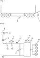
- Fig. 1 is a perspective view showing the state where a power conversion device for railway vehicle is mounted in a car-body.
- the power conversion device 2 mounted in a railway vehicle is suspended below the floor of the car-body 1.
- Fig. 2 is a view showing one example of a main circuit structure of the power conversion device 2 for railway vehicle.
- the direct current power taken from an overhead contact line 3 according to a rise of a pantograph 4 passes through the high speed circuit breaker (HB) 5 ⁇ the electromagnetic contactor (LB) 6a ⁇ charge resistor (CHRe) 7 ⁇ filter reactor (FL) 8, to charge a filter capacitor (FC) 9.
- the electromagnetic contactor (LB) 6b is turned on, three phase alternating current power is supplied to a traction motor 12, by switching of a power device element within a power unit (PU) 10, and the traction motor 12 outputs a driving torque.
- the filter reactor (FL) 8 and the brake resistor (BRe) 11 as a main heat generating body in the above-mentioned main circuit are the heat generating bodies having different maximum heat generation periods.
- the filter reactor (FL) 8 Since a reactor has a function of suppressing a voltage change, the filter reactor (FL) 8, with a proper reactor value set, mainly aims to suppress a high frequency noise of the voltage generated by switching of a semiconductor element within an inverter, to protect the overhead contact line, and to suppress a rapid discharge of electric current at a shirt-circuit accident.
- the brake resistor (BRe) 11 mainly aims to discharge electric energy within the circuit through itself at a regeneration impossible time and at an overvoltage time of the filter capacitor (FC) 9.
- the maximum heat generation period means a period during which the maximum load is imposed on the heat generating body, and in short, it is a period of generating the maximum heat generation amount.
- Fig. 3 is a view showing an arrangement of the devices within the power conversion device for railway vehicle according to a first embodiment of the invention. It shows the arrangement when the bottom of the floor surface of the railway vehicle is upwardly viewed from the ground surface: the horizontal direction of the paper is a proceeding direction of the vehicle and the vertical direction is a width (sleeper) direction of the railway track.
- a storage 13 housing a plurality of heat generating bodies (the filter reactors (FL) 8a and 8b, the power unit (PU) 10, and the brake resistor (BRe) 11) can be regarded as a wind tunnel because the cooling wind flows there.
- these heat generating bodies are arranged in series or in parallel to the flow of the cooling wind from a fan 14.
- the fan 14 may be put anywhere inside and outside of the storage (wind tunnel) as far as it can serve a role of running the cooling wind within the storage (wind tunnel) 13, or the wind inlet and the wind outlet of the cooling wind may be inverted as far as it can satisfy the cooling performance. Further, the fan 14 does not have to be particularly provided as far as the vehicle running wind satisfies the cooling performance.
- the filter reactors (FL) 8a and 8b arranged in parallel in Fig. 3 are assumed in the case where the filter reactors (FL) are provided respectively on the positive potential side and the negative potential side or the ground side within the main circuit (not illustrated in Fig. 2 ); however, it is not absolutely essential but they may be formed only on the positive potential side.
- the filter reactors (FL) 8a and 8b having the same maximum heat generation periods are arranged in parallel to a flow of the cooling wind, and the brake resistor (BRe) 11 having the maximum heat generation period different from that of the filter reactors (FL) 8a and 8b is arranged in series to a flow of the cooling wind.
- the invention is to arrange the heat generating bodies having different maximum heat generation periods in series to a flow of the cooling wind and arrange the heat generating bodies having the same or almost equal maximum heat generation periods in parallel to a flow of the cooling wind.
- the above one may be arranged within the same storage (wind tunnel) together with the other heat generating body.
- the power unit (PU) contains a semiconductor element as a power device: according to switching of this semiconductor element, the unit converts direct current power to three phase alternating current power at power running and converts the power in an inverse direction at power regeneration, hence to do a torque control of the traction motor.
- the power unit (PU) 10 generates heat according to the switching of the semiconductor element, the temperature rise amount due to the heat generation is comparatively smaller than those of the filter reactors (FL) 8a and 8b and the brake resistor (BRe) 11, and therefore, as shown in Fig. 3 , the above unit is arranged on the windward side from these devices.
- the power unit (PU) 10 has to be upsized.
- the power unit (PU) 10 the filter reactors (FL) 8a and 8b in parallel, and further the brake resistor (BRe) 11 are arranged in this order from the windward side; according to this order, the device having a small margin to the temperature is arranged on the windward side and the device having a large margin is arranged on the leeward side.
- the "margin” is a tolerance value obtained by subtracting the temperature of a device after a temperature rise due to heat generation from the heat resistant temperature of the device.
- the temperature of the cooling wind becomes higher due to the heat generation of the heat generating bodies according as they are positioned further on the leeward side. Therefore, that one having a high margin has to be arranged on the leeward side.
- the difference heat generating bodies may be arranged on any side of the windward and the leeward.
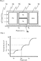
- Fig. 4 is a graph showing a relation between the position and the temperature of the cooling wind passing through the storage (wind tunnel) in the case of not considering the maximum heat generation period of each heat generating body
- Fig. 5 is a graph showing the above relation in the case of considering the maximum heat generation period of each heat generating body.
- the temperature of the cooling wind passing through the storage is estimated as the addition of each temperature rise, supposing the time when each of the heat generating bodies generates heat at the maximum load, as shown in Fig. 4 .
- the temperature of the cooling wind passing through the storage (wind tunnel) generates a difference whether or not each heat generating body is in the maximum heat generation period.
- the brake resistor (BRe) 11 is used to discharge electric energy within the circuit, when the filter reactors (FL) 8a and 8b are not used or not in the maximum load state; therefore, the heat generation amount can be regarded small. Therefore, the temperature rise of the cooling wind within the storage (wind tunnel) can be estimated as shown in Fig. 5 .
- the brake resistor (BRe) 11 Compared with the case of not considering the heat generation timing of each heat generating body in Fig. 4 , it is possible to design the brake resistor (BRe) 11 with the cooling wind temperature closer to the temperature TO of the inlet wind, or set the temperature within the storage (wind tunnel) and the temperature of the exhaust wind from the storage (wind tunnel). Similarly, at the maximum load time of the filter reactors (FL) 8a and 8b, the brake resistor (BRe) 11 is not used or it is not in the maximum load state, and therefore, the temperature rise amount can be estimated with the heat generation amount regarded small.
- heat generation of the filter reactor (FL) and the brake resistor (BRe) is dominant in a temperature rise within the storage (wind tunnel), and also their physical largeness (size) is generally dominant within the power conversion device.
- the total heat generation amount when the heat generating bodies are arranged in series within the storage (wind tunnel) is estimated more properly than in the case of the conventional arrangement and estimated smaller; therefore, it is possible to downsize the highly densified heat generating bodies and the fan, and further downsize the whole body of the power conversion device. As the result, it is possible to mount the devices within a limited rigging space.
- the power unit (PU) with a comparatively smaller temperature rise is arranged in series with the filter reactors (FL) and the brake resistor (BRe) within the storage (wind tunnel), hence to reduce the number of fans and the number of parts.
- Fig. 6 is a view showing the arrangement of the devices within the power conversion device for railway vehicle according to a second embodiment of the invention.
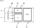
- Fig. 7 is a view showing a variation example of the arrangement. The same reference signs are attached to the same devices as those having been described in the first embodiment and their detailed description is omitted.
- the arrangement on the floor surface of the railway vehicle is viewed upwardly from the ground surface: the horizontal direction of the paper is a proceeding direction of the vehicle and the vertical direction of the paper is a width (sleeper) direction of the railway track.
- the fan 30 may be arranged anywhere inside and outside of the storage as far as it can serve a role of running the cooling wind in the storage (wind tunnel) 13, and further, as far as it can satisfy the cooling performance, the wind inlet and the wind outlet of the cooling wind may be inverted. Furthermore, as far as the cooling performance can be satisfied with the vehicle running wind, the fan 30 does not have to be provided particularly.
- the storage (wind tunnel) 13 is divided into two of 13a and 13b: in the storage (wind tunnel) 13b, the filter reactor (FL) 8 and the brake resistor (BRe) 11 having different maximum heat generation periods are arranged in series, and the power unit (PU) 10 with a comparatively smaller heat generation amount and the maximum heat generation period overlapping with that of the other heat generating bodies is arranged in the storage (wind tunnel) 13a.
- the cooling wind from the fan 30 flows to the storages (wind tunnel) 13a and 13b in a given distribution of wind amount capable of satisfying the cooling performance, to cool the respective heat generating bodies.
- an aperture ratio of the storages (wind tunnel) 13a and 13b is the value necessary for obtaining the above wind amount distribution ratio (the case of the aperture ratio 3:7 in Fig. 6 ) . According to this, the wind amount of the cooling wind can be effectively used.
- the storage (wind tunnel) 13 is divided into two on the half way, the power unit (PU) 10 and the filter reactor (FL)8 are respectively arranged there, and the brake resistor (BRe) 11 with a large heat generation amount is arranged in a way of covering the leeward side of the both.
- the cooling wind from the fan 30 flows to a side of the power unit (PU) 10 and a side of the filter reactor (FL) 8 in the storage (wind tunnel) 13 in a given distribution of the wind amount capable of satisfying the cooling performance (the case of the aperture ratio 3:7 in Fig. 7 ), and the cooling wind flows to the brake resistor (BRe) 11 from the both.
- the aperture ratio is not restricted to the ratio (3:7) shown in Figs. 6 and 7 .
- the filter reactor (FL) 8 and the brake resistor (BRe) 11 have different maximum heat generation periods; therefore, similarly to the case of the first embodiment, by considering the maximum heat generation period of each heat generating body, assuming that the temperature of the cooling wind is nearer to the temperature of the inlet wind than in the case of not considering the above, the filter reactor (FL) 8 and the brake resistor (BRe) 11 can be designed or the temperature within the storage (wind tunnel) 13 and the temperature of the exhaust wind from the storage (wind tunnel) 13 can be set.
- the power unit (PU) with a comparatively smaller temperature rise than those of the filter reactor (FL) and the brake resistor (BRe) but the maximum heat generation period overlapping with those of the above is arranged within the other storage (wind tunnel) in parallel, and by effectively making use of the cooling wind divided in a given wind amount, it is possible to reduce the number or the ability of fans and further the number of the parts.
Landscapes
- Engineering & Computer Science (AREA)
- Automation & Control Theory (AREA)
- Transportation (AREA)
- Mechanical Engineering (AREA)
- Electric Propulsion And Braking For Vehicles (AREA)
- Inverter Devices (AREA)
Abstract
Description
- This invention relates to a power conversion device for railway vehicle.
- In some of the conventional power conversion devices for railway vehicle, a cooling mechanism is individually provided in each heat generating body forming the power conversion device, so that the heat generating bodies can be surely cooled.
- On the other hand, in the case of adopting an air-cooling device as one of the cooling mechanism,
Patent Literature 1 discloses that a plurality of heat generating bodies are arranged within the same wind tunnel at the lower part of a control box mounted under the floor of the electric vehicle and that the cooling wind from a fan is used for cooling these heat generating bodies. - Patent Literature 1:
Japanese Unexamined Patent Application Publication No.7-277187 - In the case where a plurality of heat generating bodies are arranged within a single wind tunnel as disclosed in
Patent Literature 1, when heat calculation is performed on the whole wind tunnel in the state in which each of the heat generating bodies is generating the maximum load (maximum heat amount), the design will have a large margin with the heat generation amount estimated more than the actual amount, which leads to upsize the mounted devices and cooling mechanisms. - The invention aims to provide an arrangement of devices for downsizing the power conversion device for railway vehicle more than the conventional one when the wind from a fan or a running vehicle is used as a cooling wind to cool a plurality of heat generating bodies within the power conversion device in the same wind tunnel.
- In order to solve the above problem, a power conversion device rigged below a floor of a railway vehicle for driving an electric motor for use in the vehicle, is characterized in that devices generating heat and forming the power conversion device are stored in a storage where a cooling wind flows and that the devices having different maximum heat generation periods are arranged in series to a flow of the cooling wind.
- With consideration taken to the respective maximum heat generation periods of a plurality of heat generating bodies and the arrangement of the heat generating bodies having different maximum heat generation periods, it is possible to downsize the heat generating bodies and the fan and further the whole body of the power conversion device for railway vehicle, thereby enabling the installation within a limited rigging space.
-
-
Fig. 1 is a perspective view showing the state where a power conversion device for railway vehicle is mounted in a car-body. -
Fig. 2 is a view showing one example of a main circuit structure of the power conversion device for railway vehicle. -
Fig. 3 is a view showing an arrangement of the devices within the power conversion device for railway vehicle according to a first embodiment of the invention. -
Fig. 4 is a graph showing a relation between the position and the temperature of the cooling wind passing through a storage (wind tunnel) in the case of not considering the maximum heat generation period of each heat generating body. -
Fig. 5 is a graph showing a relation between the position and the temperature of the cooling wind passing through the storage (wind tunnel) in the case of considering the maximum heat generation period of each heat generating body. -
Fig. 6 is a view showing the arrangement of the devices within the power conversion device for railway vehicle according to a second embodiment of the invention. -
Fig. 7 is a view showing a variation example of the arrangement according to the second embodiment. - Hereinafter, first and second embodiments of the invention will be described using the drawings, as the form for carrying out the invention.
-
Fig. 1 is a perspective view showing the state where a power conversion device for railway vehicle is mounted in a car-body. Thepower conversion device 2 mounted in a railway vehicle is suspended below the floor of the car-body 1. -
Fig. 2 is a view showing one example of a main circuit structure of thepower conversion device 2 for railway vehicle. - By turning on a high speed circuit breaker (HB) 5 and an electromagnetic contactor (LB) 6a, the direct current power taken from an
overhead contact line 3 according to a rise of a pantograph 4 passes through the high speed circuit breaker (HB) 5 → the electromagnetic contactor (LB) 6a → charge resistor (CHRe) 7 → filter reactor (FL) 8, to charge a filter capacitor (FC) 9. Thereafter, the electromagnetic contactor (LB) 6b is turned on, three phase alternating current power is supplied to atraction motor 12, by switching of a power device element within a power unit (PU) 10, and thetraction motor 12 outputs a driving torque. - These devices generate not a little heat at their use and therefore, that one having a large amount of heat generation has to be positively cooled.
- Here, the filter reactor (FL) 8 and the brake resistor (BRe) 11 as a main heat generating body in the above-mentioned main circuit are the heat generating bodies having different maximum heat generation periods.
- Since a reactor has a function of suppressing a voltage change, the filter reactor (FL) 8, with a proper reactor value set, mainly aims to suppress a high frequency noise of the voltage generated by switching of a semiconductor element within an inverter, to protect the overhead contact line, and to suppress a rapid discharge of electric current at a shirt-circuit accident.
- Further, the brake resistor (BRe) 11 mainly aims to discharge electric energy within the circuit through itself at a regeneration impossible time and at an overvoltage time of the filter capacitor (FC) 9.
- These two devices do not have the maximum heat generation amounts at the same time; therefore, the maximum heat generation periods are different. Here, the maximum heat generation period means a period during which the maximum load is imposed on the heat generating body, and in short, it is a period of generating the maximum heat generation amount.
-
Fig. 3 is a view showing an arrangement of the devices within the power conversion device for railway vehicle according to a first embodiment of the invention. It shows the arrangement when the bottom of the floor surface of the railway vehicle is upwardly viewed from the ground surface: the horizontal direction of the paper is a proceeding direction of the vehicle and the vertical direction is a width (sleeper) direction of the railway track. - A
storage 13 housing a plurality of heat generating bodies (the filter reactors (FL) 8a and 8b, the power unit (PU) 10, and the brake resistor (BRe) 11) can be regarded as a wind tunnel because the cooling wind flows there. Within the storage (wind tunnel) 13, these heat generating bodies are arranged in series or in parallel to the flow of the cooling wind from afan 14. - Here, the
fan 14 may be put anywhere inside and outside of the storage (wind tunnel) as far as it can serve a role of running the cooling wind within the storage (wind tunnel) 13, or the wind inlet and the wind outlet of the cooling wind may be inverted as far as it can satisfy the cooling performance. Further, thefan 14 does not have to be particularly provided as far as the vehicle running wind satisfies the cooling performance. - Further, the filter reactors (FL) 8a and 8b arranged in parallel in
Fig. 3 are assumed in the case where the filter reactors (FL) are provided respectively on the positive potential side and the negative potential side or the ground side within the main circuit (not illustrated inFig. 2 ); however, it is not absolutely essential but they may be formed only on the positive potential side. - As mentioned above, when the plural heat generating bodies are arranged within the same storage (wind tunnel), it is necessary to design each size and arrangement of the respective heat generating bodies, considering the influence by the respective heat generating bodies on the temperature of the cooling wind.
- As shown in
Fig. 3 , in the first embodiment, the filter reactors (FL) 8a and 8b having the same maximum heat generation periods are arranged in parallel to a flow of the cooling wind, and the brake resistor (BRe) 11 having the maximum heat generation period different from that of the filter reactors (FL) 8a and 8b is arranged in series to a flow of the cooling wind. - In short, the invention is to arrange the heat generating bodies having different maximum heat generation periods in series to a flow of the cooling wind and arrange the heat generating bodies having the same or almost equal maximum heat generation periods in parallel to a flow of the cooling wind.
- Further, even in the different heat generating bodies with the overlapping maximum heat generation periods, when one has a smaller temperature rise amount due to the heat generation than the other, the above one may be arranged within the same storage (wind tunnel) together with the other heat generating body.
- Consideration is given to, for example, the power unit (PU). The power unit (PU) contains a semiconductor element as a power device: according to switching of this semiconductor element, the unit converts direct current power to three phase alternating current power at power running and converts the power in an inverse direction at power regeneration, hence to do a torque control of the traction motor.
- Although the power unit (PU) 10 generates heat according to the switching of the semiconductor element, the temperature rise amount due to the heat generation is comparatively smaller than those of the filter reactors (FL) 8a and 8b and the brake resistor (BRe) 11, and therefore, as shown in
Fig. 3 , the above unit is arranged on the windward side from these devices. - The reason why the above unit is arranged on the windward side is that if it is arranged on the leeward side, the unit receives the cooling wind having passed through the filter reactors (FL) 8a and 8b and the brake resistor (BRe) 11, causing a necessity for withstanding the exhaust heat; therefore, in order to satisfy this, the power unit (PU) 10 has to be upsized.
- Further, in the first embodiment, as shown in
Fig. 3 , the power unit (PU) 10, the filter reactors (FL) 8a and 8b in parallel, and further the brake resistor (BRe) 11 are arranged in this order from the windward side; according to this order, the device having a small margin to the temperature is arranged on the windward side and the device having a large margin is arranged on the leeward side. - Here, the "margin" is a tolerance value obtained by subtracting the temperature of a device after a temperature rise due to heat generation from the heat resistant temperature of the device. When the plural heat generating bodies are arranged in series within the same wind tunnel, the temperature of the cooling wind becomes higher due to the heat generation of the heat generating bodies according as they are positioned further on the leeward side. Therefore, that one having a high margin has to be arranged on the leeward side. However, if the difference heat generating bodies have the same margin, they may be arranged on any side of the windward and the leeward.
- Next, the temperature of the cooling wind passing through the storage (wind tunnel) is examined in the case of not considering the maximum heat generation period of each heat generating body and in the case of considering the above.
Fig. 4 is a graph showing a relation between the position and the temperature of the cooling wind passing through the storage (wind tunnel) in the case of not considering the maximum heat generation period of each heat generating body, whileFig. 5 is a graph showing the above relation in the case of considering the maximum heat generation period of each heat generating body. - In the case of not considering the maximum heat generation period of each heat generating body, the temperature of the cooling wind passing through the storage (wind tunnel) is estimated as the addition of each temperature rise, supposing the time when each of the heat generating bodies generates heat at the maximum load, as shown in
Fig. 4 . - On the other hand, in the case of considering the maximum heat generation period of each heat generating body, the temperature of the cooling wind passing through the storage (wind tunnel) generates a difference whether or not each heat generating body is in the maximum heat generation period. For example, at a regeneration impossible time, the brake resistor (BRe) 11 is used to discharge electric energy within the circuit, when the filter reactors (FL) 8a and 8b are not used or not in the maximum load state; therefore, the heat generation amount can be regarded small. Therefore, the temperature rise of the cooling wind within the storage (wind tunnel) can be estimated as shown in
Fig. 5 . - Compared with the case of not considering the heat generation timing of each heat generating body in
Fig. 4 , it is possible to design the brake resistor (BRe) 11 with the cooling wind temperature closer to the temperature TO of the inlet wind, or set the temperature within the storage (wind tunnel) and the temperature of the exhaust wind from the storage (wind tunnel). Similarly, at the maximum load time of the filter reactors (FL) 8a and 8b, the brake resistor (BRe) 11 is not used or it is not in the maximum load state, and therefore, the temperature rise amount can be estimated with the heat generation amount regarded small. - As mentioned above, in the power conversion device for railway vehicle, heat generation of the filter reactor (FL) and the brake resistor (BRe) is dominant in a temperature rise within the storage (wind tunnel), and also their physical largeness (size) is generally dominant within the power conversion device. In this situation, by adopting the invention, the total heat generation amount when the heat generating bodies are arranged in series within the storage (wind tunnel) is estimated more properly than in the case of the conventional arrangement and estimated smaller; therefore, it is possible to downsize the highly densified heat generating bodies and the fan, and further downsize the whole body of the power conversion device. As the result, it is possible to mount the devices within a limited rigging space.
- Further, in the first embodiment, the power unit (PU) with a comparatively smaller temperature rise is arranged in series with the filter reactors (FL) and the brake resistor (BRe) within the storage (wind tunnel), hence to reduce the number of fans and the number of parts.
-
Fig. 6 is a view showing the arrangement of the devices within the power conversion device for railway vehicle according to a second embodiment of the invention.Fig. 7 is a view showing a variation example of the arrangement. The same reference signs are attached to the same devices as those having been described in the first embodiment and their detailed description is omitted. Similarly toFig. 3 , the arrangement on the floor surface of the railway vehicle is viewed upwardly from the ground surface: the horizontal direction of the paper is a proceeding direction of the vehicle and the vertical direction of the paper is a width (sleeper) direction of the railway track. - Here, the
fan 30 may be arranged anywhere inside and outside of the storage as far as it can serve a role of running the cooling wind in the storage (wind tunnel) 13, and further, as far as it can satisfy the cooling performance, the wind inlet and the wind outlet of the cooling wind may be inverted. Furthermore, as far as the cooling performance can be satisfied with the vehicle running wind, thefan 30 does not have to be provided particularly. - In the arrangement as shown in
Fig. 6 , the storage (wind tunnel) 13 is divided into two of 13a and 13b: in the storage (wind tunnel) 13b, the filter reactor (FL) 8 and the brake resistor (BRe) 11 having different maximum heat generation periods are arranged in series, and the power unit (PU) 10 with a comparatively smaller heat generation amount and the maximum heat generation period overlapping with that of the other heat generating bodies is arranged in the storage (wind tunnel) 13a. - After this, the cooling wind from the
fan 30 flows to the storages (wind tunnel) 13a and 13b in a given distribution of wind amount capable of satisfying the cooling performance, to cool the respective heat generating bodies. Here, when flowing in the given distribution of the wind amount, an aperture ratio of the storages (wind tunnel) 13a and 13b is the value necessary for obtaining the above wind amount distribution ratio (the case of the aperture ratio 3:7 inFig. 6 ) . According to this, the wind amount of the cooling wind can be effectively used. - Further, in the arrangement as shown in
Fig. 7 , the storage (wind tunnel) 13 is divided into two on the half way, the power unit (PU) 10 and the filter reactor (FL)8 are respectively arranged there, and the brake resistor (BRe) 11 with a large heat generation amount is arranged in a way of covering the leeward side of the both. - After this, the cooling wind from the
fan 30 flows to a side of the power unit (PU) 10 and a side of the filter reactor (FL) 8 in the storage (wind tunnel) 13 in a given distribution of the wind amount capable of satisfying the cooling performance (the case of the aperture ratio 3:7 inFig. 7 ), and the cooling wind flows to the brake resistor (BRe) 11 from the both. According to this, the wind amount of the cooling wind can be effectively used. Here, the aperture ratio is not restricted to the ratio (3:7) shown inFigs. 6 and7 . - Here, the filter reactor (FL) 8 and the brake resistor (BRe) 11 have different maximum heat generation periods; therefore, similarly to the case of the first embodiment, by considering the maximum heat generation period of each heat generating body, assuming that the temperature of the cooling wind is nearer to the temperature of the inlet wind than in the case of not considering the above, the filter reactor (FL) 8 and the brake resistor (BRe) 11 can be designed or the temperature within the storage (wind tunnel) 13 and the temperature of the exhaust wind from the storage (wind tunnel) 13 can be set.
- As mentioned above, also according to the second embodiment, the same effect as that having been described in the first embodiment can be obtained. Further, in the second embodiment, the power unit (PU) with a comparatively smaller temperature rise than those of the filter reactor (FL) and the brake resistor (BRe) but the maximum heat generation period overlapping with those of the above is arranged within the other storage (wind tunnel) in parallel, and by effectively making use of the cooling wind divided in a given wind amount, it is possible to reduce the number or the ability of fans and further the number of the parts.
- 1 car-body, 2 power conversion device, 3 overhead contact line, 4 pantograph, 5 high speed circuit breaker (HB), 6a, 6b electromagnetic contactor (LB), 7 charge resistor (CHRe), 8, 8a, 8b filter reactor (FL), 9 filter capacitor (FC), 10 power unit (PU), 11 brake resistor (BRe), 12 traction motor (M1 - M4), 13, 13a, 13b storage (wind tunnel), 14, 30 fan
Claims (10)
- A power conversion device for railway vehicle rigged below a floor of the railway vehicle to supply power to an electric motor of driving the railway vehicle, characterized in thata device forming the power conversion device, which generates heat, is stored in a storage where a cooling wind flows, andthe devices having different maximum heat generation periods are arranged in series to a flow of the cooling wind.
- The power conversion device for railway vehicle according to claim 1, characterized in that
the devices having the same or almost similar maximum heat generation periods are arranged in parallel to the flow of the cooling wind. - The power conversion device for railway vehicle according to claim 1 or 2, characterized in that
the device having a smaller one, of a tolerance value obtained by subtracting a temperature of the device after a temperature rise due to heat generation from a heat resistant temperature of the device, is arranged on a windward side of the cooling wind and the device having a larger tolerance value is arranged on a leeward side of the cooling wind. - The power conversion device for railway vehicle according to one of claims 1 to 3, characterized in that
of the different devices having the overlapping maximum heat generation periods, a first device having a smaller temperature rise due to heat generation than that of the other device is arranged together within the storage. - The power conversion device for railway vehicle according to claim 4, characterized in thatthe storage is divided in parallel to the flow of the cooling wind, andthe first device is arranged in one part of the storage and the other devices having the same maximum heat generation periods are arranged in the other part of the storage.
- The power conversion device for railway vehicle according to claim 5, characterized in that
the cooling wind is divided in a given wind amount and fed to the one and the other parts of the storage. - The power conversion device for railway vehicle according to one of claims 1 to 6, characterized in that
the cooling wind is a wind fed by a fan provided inside or outside of the storage, or a vehicle running wind. - The power conversion device for railway vehicle according to claim 1, characterized in that
a filter reactor and a brake resistor as the devices are arranged in this order from the windward side of the cooling wind. - The power conversion device for railway vehicle according to claim 3, characterized in that
a power unit, a filter reactor, and a brake resistor as the devices are arranged in this order from the windward side of the cooling wind. - The power conversion device for railway vehicle according to claim 5, characterized in thatthe first device is a power unit, anda filter reactor and a brake resistor as the other devices are arranged in this order from the windward side of the cooling wind.
Applications Claiming Priority (2)
| Application Number | Priority Date | Filing Date | Title |
|---|---|---|---|
| JP2018242977 | 2018-12-26 | ||
| PCT/JP2019/042270 WO2020137133A1 (en) | 2018-12-26 | 2019-10-29 | Power conversion device for railway vehicle |
Publications (3)
| Publication Number | Publication Date |
|---|---|
| EP3904174A1 true EP3904174A1 (en) | 2021-11-03 |
| EP3904174A4 EP3904174A4 (en) | 2022-10-12 |
| EP3904174B1 EP3904174B1 (en) | 2023-08-16 |
Family
ID=71126307
Family Applications (1)
| Application Number | Title | Priority Date | Filing Date |
|---|---|---|---|
| EP19905746.4A Active EP3904174B1 (en) | 2018-12-26 | 2019-10-29 | Power conversion device for railway vehicle |
Country Status (3)
| Country | Link |
|---|---|
| EP (1) | EP3904174B1 (en) |
| JP (1) | JP7072675B2 (en) |
| WO (1) | WO2020137133A1 (en) |
Cited By (1)
| Publication number | Priority date | Publication date | Assignee | Title |
|---|---|---|---|---|
| EP3904174A4 (en) * | 2018-12-26 | 2022-10-12 | Hitachi, Ltd. | POWER CONVERSION DEVICE FOR RAILWAY VEHICLE |
Family Cites Families (12)
| Publication number | Priority date | Publication date | Assignee | Title |
|---|---|---|---|---|
| JPH07277187A (en) | 1994-04-08 | 1995-10-24 | Toshiba Corp | Electric car control box |
| WO1996009198A1 (en) | 1994-09-20 | 1996-03-28 | Hitachi, Ltd. | Railway vehicle and method for producing the same |
| JPH1095334A (en) * | 1996-09-25 | 1998-04-14 | Toshiba Transport Eng Kk | Semiconductor control device for vehicles |
| DE19951356A1 (en) * | 1999-10-26 | 2001-05-03 | Daimler Chrysler Ag | Underfloor container for rail vehicles |
| JP4195834B2 (en) | 2003-06-13 | 2008-12-17 | 株式会社東芝 | Power conversion system for AC trains |
| WO2012032642A1 (en) | 2010-09-09 | 2012-03-15 | 三菱電機株式会社 | Power semiconductor module, power conversion apparatus, and railroad vehicle |
| JP2012256767A (en) * | 2011-06-10 | 2012-12-27 | Toyo Electric Mfg Co Ltd | Forced-air cooling semiconductor cooling device |
| JP6048607B1 (en) * | 2016-04-15 | 2016-12-21 | 富士電機株式会社 | Railway vehicle power converter |
| CN106314451B (en) * | 2016-11-07 | 2018-05-29 | 中车大连电力牵引研发中心有限公司 | Power train in vehicle application unit |
| FR3065936B1 (en) * | 2017-05-05 | 2019-07-05 | Alstom Transport Technologies | TENSION CHAIN COOLING SYSTEM FOR TRANSPORT VEHICLE, TRACTION CHAIN AND ELECTRIC VEHICLE OF TRANSPORT THEREFOR |
| GB2573151B (en) | 2018-04-26 | 2020-04-29 | Hitachi Ltd | Railway vehicle cooling system and method using air-conditioner air flow |
| WO2020137133A1 (en) * | 2018-12-26 | 2020-07-02 | 株式会社日立製作所 | Power conversion device for railway vehicle |
-
2019
- 2019-10-29 WO PCT/JP2019/042270 patent/WO2020137133A1/en not_active Ceased
- 2019-10-29 JP JP2020562861A patent/JP7072675B2/en active Active
- 2019-10-29 EP EP19905746.4A patent/EP3904174B1/en active Active
Cited By (1)
| Publication number | Priority date | Publication date | Assignee | Title |
|---|---|---|---|---|
| EP3904174A4 (en) * | 2018-12-26 | 2022-10-12 | Hitachi, Ltd. | POWER CONVERSION DEVICE FOR RAILWAY VEHICLE |
Also Published As
| Publication number | Publication date |
|---|---|
| JP7072675B2 (en) | 2022-05-20 |
| WO2020137133A1 (en) | 2020-07-02 |
| EP3904174A4 (en) | 2022-10-12 |
| EP3904174B1 (en) | 2023-08-16 |
| JPWO2020137133A1 (en) | 2021-10-14 |
Similar Documents
| Publication | Publication Date | Title |
|---|---|---|
| EP2340957B1 (en) | Propulsion control device for electric car | |
| JP5548280B2 (en) | Drive system and drive system for railway vehicle | |
| EP2502773B1 (en) | System for supplying propulsion energy from an auxiliary drive and method of making same | |
| JP5048384B2 (en) | Battery charger for railway vehicles | |
| JP5214065B1 (en) | Electric car main circuit system | |
| EP2511123B1 (en) | Propulsion control device | |
| JP6438266B2 (en) | Dump truck | |
| JP2008263741A5 (en) | ||
| JP2000134701A (en) | Power conversion equipment for railway vehicles | |
| CN103475236A (en) | Tractive current transformer | |
| EP3904174A1 (en) | Power conversion device for railway vehicle | |
| CN104108319B (en) | Electric motor car control device and electric motor car control method | |
| KR20180019379A (en) | Integrated power conversion apparatus for electric railway vehicle and electric railway vehicle including the same | |
| JP6967162B2 (en) | A drive device for a railroad vehicle, this mounting method, a railroad vehicle equipped with the drive device, and this production method. | |
| JP6666815B2 (en) | Cooling device, bogie and railcar equipped with cooling device | |
| TWI589463B (en) | High-speed railway vehicle power conversion system and control method of high-speed railway vehicle power conversion system | |
| JP5277433B2 (en) | Electric vehicle drive device | |
| JP6259778B2 (en) | Railway vehicle drive system | |
| JP6240023B2 (en) | Power converter and railway vehicle equipped with the same | |
| JP5058545B2 (en) | Electric vehicle control device | |
| JP2013196840A (en) | Cooling structure for battery pack | |
| JP2006149199A (en) | Railway vehicle power converter | |
| TAGUCHI et al. | Development of a Traction Circuit for Battery-powered and AC-fed Dual Source EMU and Running Test Evaluation of the On-board Battery Performance | |
| JPWO2017037795A1 (en) | RAILWAY VEHICLE, VEHICLE POWER CONVERSION DEVICE AND METHOD | |
| JP7483186B2 (en) | Power Conversion Equipment |
Legal Events
| Date | Code | Title | Description |
|---|---|---|---|
| STAA | Information on the status of an ep patent application or granted ep patent |
Free format text: STATUS: THE INTERNATIONAL PUBLICATION HAS BEEN MADE |
|
| PUAI | Public reference made under article 153(3) epc to a published international application that has entered the european phase |
Free format text: ORIGINAL CODE: 0009012 |
|
| STAA | Information on the status of an ep patent application or granted ep patent |
Free format text: STATUS: REQUEST FOR EXAMINATION WAS MADE |
|
| 17P | Request for examination filed |
Effective date: 20210607 |
|
| AK | Designated contracting states |
Kind code of ref document: A1 Designated state(s): AL AT BE BG CH CY CZ DE DK EE ES FI FR GB GR HR HU IE IS IT LI LT LU LV MC MK MT NL NO PL PT RO RS SE SI SK SM TR |
|
| DAV | Request for validation of the european patent (deleted) | ||
| DAX | Request for extension of the european patent (deleted) | ||
| A4 | Supplementary search report drawn up and despatched |
Effective date: 20220908 |
|
| RIC1 | Information provided on ipc code assigned before grant |
Ipc: B61C 17/00 20060101AFI20220902BHEP |
|
| GRAP | Despatch of communication of intention to grant a patent |
Free format text: ORIGINAL CODE: EPIDOSNIGR1 |
|
| STAA | Information on the status of an ep patent application or granted ep patent |
Free format text: STATUS: GRANT OF PATENT IS INTENDED |
|
| INTG | Intention to grant announced |
Effective date: 20230306 |
|
| GRAS | Grant fee paid |
Free format text: ORIGINAL CODE: EPIDOSNIGR3 |
|
| GRAA | (expected) grant |
Free format text: ORIGINAL CODE: 0009210 |
|
| STAA | Information on the status of an ep patent application or granted ep patent |
Free format text: STATUS: THE PATENT HAS BEEN GRANTED |
|
| AK | Designated contracting states |
Kind code of ref document: B1 Designated state(s): AL AT BE BG CH CY CZ DE DK EE ES FI FR GB GR HR HU IE IS IT LI LT LU LV MC MK MT NL NO PL PT RO RS SE SI SK SM TR |
|
| REG | Reference to a national code |
Ref country code: CH Ref legal event code: EP Ref country code: DE Ref legal event code: R096 Ref document number: 602019035344 Country of ref document: DE |
|
| REG | Reference to a national code |
Ref country code: IE Ref legal event code: FG4D |
|
| REG | Reference to a national code |
Ref country code: LT Ref legal event code: MG9D |
|
| REG | Reference to a national code |
Ref country code: NL Ref legal event code: MP Effective date: 20230816 |
|
| REG | Reference to a national code |
Ref country code: AT Ref legal event code: MK05 Ref document number: 1599783 Country of ref document: AT Kind code of ref document: T Effective date: 20230816 |
|
| PG25 | Lapsed in a contracting state [announced via postgrant information from national office to epo] |
Ref country code: GR Free format text: LAPSE BECAUSE OF FAILURE TO SUBMIT A TRANSLATION OF THE DESCRIPTION OR TO PAY THE FEE WITHIN THE PRESCRIBED TIME-LIMIT Effective date: 20231117 |
|
| PG25 | Lapsed in a contracting state [announced via postgrant information from national office to epo] |
Ref country code: IS Free format text: LAPSE BECAUSE OF FAILURE TO SUBMIT A TRANSLATION OF THE DESCRIPTION OR TO PAY THE FEE WITHIN THE PRESCRIBED TIME-LIMIT Effective date: 20231216 |
|
| PG25 | Lapsed in a contracting state [announced via postgrant information from national office to epo] |
Ref country code: SE Free format text: LAPSE BECAUSE OF FAILURE TO SUBMIT A TRANSLATION OF THE DESCRIPTION OR TO PAY THE FEE WITHIN THE PRESCRIBED TIME-LIMIT Effective date: 20230816 Ref country code: RS Free format text: LAPSE BECAUSE OF FAILURE TO SUBMIT A TRANSLATION OF THE DESCRIPTION OR TO PAY THE FEE WITHIN THE PRESCRIBED TIME-LIMIT Effective date: 20230816 Ref country code: PT Free format text: LAPSE BECAUSE OF FAILURE TO SUBMIT A TRANSLATION OF THE DESCRIPTION OR TO PAY THE FEE WITHIN THE PRESCRIBED TIME-LIMIT Effective date: 20231218 Ref country code: NO Free format text: LAPSE BECAUSE OF FAILURE TO SUBMIT A TRANSLATION OF THE DESCRIPTION OR TO PAY THE FEE WITHIN THE PRESCRIBED TIME-LIMIT Effective date: 20231116 Ref country code: NL Free format text: LAPSE BECAUSE OF FAILURE TO SUBMIT A TRANSLATION OF THE DESCRIPTION OR TO PAY THE FEE WITHIN THE PRESCRIBED TIME-LIMIT Effective date: 20230816 Ref country code: LV Free format text: LAPSE BECAUSE OF FAILURE TO SUBMIT A TRANSLATION OF THE DESCRIPTION OR TO PAY THE FEE WITHIN THE PRESCRIBED TIME-LIMIT Effective date: 20230816 Ref country code: LT Free format text: LAPSE BECAUSE OF FAILURE TO SUBMIT A TRANSLATION OF THE DESCRIPTION OR TO PAY THE FEE WITHIN THE PRESCRIBED TIME-LIMIT Effective date: 20230816 Ref country code: IS Free format text: LAPSE BECAUSE OF FAILURE TO SUBMIT A TRANSLATION OF THE DESCRIPTION OR TO PAY THE FEE WITHIN THE PRESCRIBED TIME-LIMIT Effective date: 20231216 Ref country code: HR Free format text: LAPSE BECAUSE OF FAILURE TO SUBMIT A TRANSLATION OF THE DESCRIPTION OR TO PAY THE FEE WITHIN THE PRESCRIBED TIME-LIMIT Effective date: 20230816 Ref country code: GR Free format text: LAPSE BECAUSE OF FAILURE TO SUBMIT A TRANSLATION OF THE DESCRIPTION OR TO PAY THE FEE WITHIN THE PRESCRIBED TIME-LIMIT Effective date: 20231117 Ref country code: FI Free format text: LAPSE BECAUSE OF FAILURE TO SUBMIT A TRANSLATION OF THE DESCRIPTION OR TO PAY THE FEE WITHIN THE PRESCRIBED TIME-LIMIT Effective date: 20230816 Ref country code: AT Free format text: LAPSE BECAUSE OF FAILURE TO SUBMIT A TRANSLATION OF THE DESCRIPTION OR TO PAY THE FEE WITHIN THE PRESCRIBED TIME-LIMIT Effective date: 20230816 |
|
| PG25 | Lapsed in a contracting state [announced via postgrant information from national office to epo] |
Ref country code: PL Free format text: LAPSE BECAUSE OF FAILURE TO SUBMIT A TRANSLATION OF THE DESCRIPTION OR TO PAY THE FEE WITHIN THE PRESCRIBED TIME-LIMIT Effective date: 20230816 |
|
| PG25 | Lapsed in a contracting state [announced via postgrant information from national office to epo] |
Ref country code: ES Free format text: LAPSE BECAUSE OF FAILURE TO SUBMIT A TRANSLATION OF THE DESCRIPTION OR TO PAY THE FEE WITHIN THE PRESCRIBED TIME-LIMIT Effective date: 20230816 |
|
| PG25 | Lapsed in a contracting state [announced via postgrant information from national office to epo] |
Ref country code: SM Free format text: LAPSE BECAUSE OF FAILURE TO SUBMIT A TRANSLATION OF THE DESCRIPTION OR TO PAY THE FEE WITHIN THE PRESCRIBED TIME-LIMIT Effective date: 20230816 Ref country code: RO Free format text: LAPSE BECAUSE OF FAILURE TO SUBMIT A TRANSLATION OF THE DESCRIPTION OR TO PAY THE FEE WITHIN THE PRESCRIBED TIME-LIMIT Effective date: 20230816 Ref country code: ES Free format text: LAPSE BECAUSE OF FAILURE TO SUBMIT A TRANSLATION OF THE DESCRIPTION OR TO PAY THE FEE WITHIN THE PRESCRIBED TIME-LIMIT Effective date: 20230816 Ref country code: EE Free format text: LAPSE BECAUSE OF FAILURE TO SUBMIT A TRANSLATION OF THE DESCRIPTION OR TO PAY THE FEE WITHIN THE PRESCRIBED TIME-LIMIT Effective date: 20230816 Ref country code: DK Free format text: LAPSE BECAUSE OF FAILURE TO SUBMIT A TRANSLATION OF THE DESCRIPTION OR TO PAY THE FEE WITHIN THE PRESCRIBED TIME-LIMIT Effective date: 20230816 Ref country code: CZ Free format text: LAPSE BECAUSE OF FAILURE TO SUBMIT A TRANSLATION OF THE DESCRIPTION OR TO PAY THE FEE WITHIN THE PRESCRIBED TIME-LIMIT Effective date: 20230816 Ref country code: SK Free format text: LAPSE BECAUSE OF FAILURE TO SUBMIT A TRANSLATION OF THE DESCRIPTION OR TO PAY THE FEE WITHIN THE PRESCRIBED TIME-LIMIT Effective date: 20230816 |
|
| REG | Reference to a national code |
Ref country code: DE Ref legal event code: R119 Ref document number: 602019035344 Country of ref document: DE |
|
| PG25 | Lapsed in a contracting state [announced via postgrant information from national office to epo] |
Ref country code: MC Free format text: LAPSE BECAUSE OF FAILURE TO SUBMIT A TRANSLATION OF THE DESCRIPTION OR TO PAY THE FEE WITHIN THE PRESCRIBED TIME-LIMIT Effective date: 20230816 |
|
| REG | Reference to a national code |
Ref country code: CH Ref legal event code: PL |
|
| REG | Reference to a national code |
Ref country code: BE Ref legal event code: MM Effective date: 20231031 |
|
| PG25 | Lapsed in a contracting state [announced via postgrant information from national office to epo] |
Ref country code: LU Free format text: LAPSE BECAUSE OF NON-PAYMENT OF DUE FEES Effective date: 20231029 |
|
| PLBE | No opposition filed within time limit |
Free format text: ORIGINAL CODE: 0009261 |
|
| STAA | Information on the status of an ep patent application or granted ep patent |
Free format text: STATUS: NO OPPOSITION FILED WITHIN TIME LIMIT |
|
| PG25 | Lapsed in a contracting state [announced via postgrant information from national office to epo] |
Ref country code: LU Free format text: LAPSE BECAUSE OF NON-PAYMENT OF DUE FEES Effective date: 20231029 |
|
| PG25 | Lapsed in a contracting state [announced via postgrant information from national office to epo] |
Ref country code: CH Free format text: LAPSE BECAUSE OF NON-PAYMENT OF DUE FEES Effective date: 20231031 |
|
| 26N | No opposition filed |
Effective date: 20240517 |
|
| PG25 | Lapsed in a contracting state [announced via postgrant information from national office to epo] |
Ref country code: FR Free format text: LAPSE BECAUSE OF NON-PAYMENT OF DUE FEES Effective date: 20231031 Ref country code: DE Free format text: LAPSE BECAUSE OF NON-PAYMENT OF DUE FEES Effective date: 20240501 Ref country code: CH Free format text: LAPSE BECAUSE OF NON-PAYMENT OF DUE FEES Effective date: 20231031 Ref country code: SI Free format text: LAPSE BECAUSE OF FAILURE TO SUBMIT A TRANSLATION OF THE DESCRIPTION OR TO PAY THE FEE WITHIN THE PRESCRIBED TIME-LIMIT Effective date: 20230816 |
|
| PG25 | Lapsed in a contracting state [announced via postgrant information from national office to epo] |
Ref country code: BE Free format text: LAPSE BECAUSE OF NON-PAYMENT OF DUE FEES Effective date: 20231031 |
|
| PG25 | Lapsed in a contracting state [announced via postgrant information from national office to epo] |
Ref country code: IE Free format text: LAPSE BECAUSE OF NON-PAYMENT OF DUE FEES Effective date: 20231029 |
|
| PG25 | Lapsed in a contracting state [announced via postgrant information from national office to epo] |
Ref country code: IE Free format text: LAPSE BECAUSE OF NON-PAYMENT OF DUE FEES Effective date: 20231029 |
|
| PG25 | Lapsed in a contracting state [announced via postgrant information from national office to epo] |
Ref country code: BG Free format text: LAPSE BECAUSE OF FAILURE TO SUBMIT A TRANSLATION OF THE DESCRIPTION OR TO PAY THE FEE WITHIN THE PRESCRIBED TIME-LIMIT Effective date: 20230816 |
|
| PG25 | Lapsed in a contracting state [announced via postgrant information from national office to epo] |
Ref country code: BG Free format text: LAPSE BECAUSE OF FAILURE TO SUBMIT A TRANSLATION OF THE DESCRIPTION OR TO PAY THE FEE WITHIN THE PRESCRIBED TIME-LIMIT Effective date: 20230816 |
|
| PG25 | Lapsed in a contracting state [announced via postgrant information from national office to epo] |
Ref country code: IT Free format text: LAPSE BECAUSE OF NON-PAYMENT OF DUE FEES Effective date: 20231029 |
|
| PG25 | Lapsed in a contracting state [announced via postgrant information from national office to epo] |
Ref country code: IT Free format text: LAPSE BECAUSE OF NON-PAYMENT OF DUE FEES Effective date: 20231029 |
|
| PG25 | Lapsed in a contracting state [announced via postgrant information from national office to epo] |
Ref country code: CY Free format text: LAPSE BECAUSE OF FAILURE TO SUBMIT A TRANSLATION OF THE DESCRIPTION OR TO PAY THE FEE WITHIN THE PRESCRIBED TIME-LIMIT; INVALID AB INITIO Effective date: 20191029 |
|
| PG25 | Lapsed in a contracting state [announced via postgrant information from national office to epo] |
Ref country code: HU Free format text: LAPSE BECAUSE OF FAILURE TO SUBMIT A TRANSLATION OF THE DESCRIPTION OR TO PAY THE FEE WITHIN THE PRESCRIBED TIME-LIMIT; INVALID AB INITIO Effective date: 20191029 |
|
| PGFP | Annual fee paid to national office [announced via postgrant information from national office to epo] |
Ref country code: GB Payment date: 20250923 Year of fee payment: 7 |
|
| PG25 | Lapsed in a contracting state [announced via postgrant information from national office to epo] |
Ref country code: TR Free format text: LAPSE BECAUSE OF FAILURE TO SUBMIT A TRANSLATION OF THE DESCRIPTION OR TO PAY THE FEE WITHIN THE PRESCRIBED TIME-LIMIT Effective date: 20230816 |