EP3904170A1 - Brake operation device - Google Patents
Brake operation device Download PDFInfo
- Publication number
- EP3904170A1 EP3904170A1 EP20171695.8A EP20171695A EP3904170A1 EP 3904170 A1 EP3904170 A1 EP 3904170A1 EP 20171695 A EP20171695 A EP 20171695A EP 3904170 A1 EP3904170 A1 EP 3904170A1
- Authority
- EP
- European Patent Office
- Prior art keywords
- brake
- mode
- control module
- operation device
- vehicle
- Prior art date
- Legal status (The legal status is an assumption and is not a legal conclusion. Google has not performed a legal analysis and makes no representation as to the accuracy of the status listed.)
- Granted
Links
Images

Classifications
-
- B—PERFORMING OPERATIONS; TRANSPORTING
- B60—VEHICLES IN GENERAL
- B60T—VEHICLE BRAKE CONTROL SYSTEMS OR PARTS THEREOF; BRAKE CONTROL SYSTEMS OR PARTS THEREOF, IN GENERAL; ARRANGEMENT OF BRAKING ELEMENTS ON VEHICLES IN GENERAL; PORTABLE DEVICES FOR PREVENTING UNWANTED MOVEMENT OF VEHICLES; VEHICLE MODIFICATIONS TO FACILITATE COOLING OF BRAKES
- B60T17/00—Component parts, details, or accessories of power brake systems not covered by groups B60T8/00, B60T13/00 or B60T15/00, or presenting other characteristic features
- B60T17/18—Safety devices; Monitoring
- B60T17/22—Devices for monitoring or checking brake systems; Signal devices
-
- B—PERFORMING OPERATIONS; TRANSPORTING
- B60—VEHICLES IN GENERAL
- B60T—VEHICLE BRAKE CONTROL SYSTEMS OR PARTS THEREOF; BRAKE CONTROL SYSTEMS OR PARTS THEREOF, IN GENERAL; ARRANGEMENT OF BRAKING ELEMENTS ON VEHICLES IN GENERAL; PORTABLE DEVICES FOR PREVENTING UNWANTED MOVEMENT OF VEHICLES; VEHICLE MODIFICATIONS TO FACILITATE COOLING OF BRAKES
- B60T7/00—Brake-action initiating means
- B60T7/02—Brake-action initiating means for personal initiation
- B60T7/08—Brake-action initiating means for personal initiation hand actuated
- B60T7/085—Brake-action initiating means for personal initiation hand actuated by electrical means, e.g. travel, force sensors
Definitions
- the invention relates to a brake operation device for a vehicle.
- electro-pneumatic brake actuators are commonly used in commercial vehicles. In most cases, these brake actuators use a pneumatic energy source via pneumatic cylinders in order to realize the actuation of both the service brake and the parking brake.
- the parking brake function is realized by using a separate brake actuator that can be operated independently of the service brake actuator.
- the design of a spring based parking brake actuator allows a single brake actuation to be achieved even without compressed air as the energy source for the actuation. In the event of a pressure loss in the brake system, a pre-tensioned spring in the parking brake chamber provides sufficient braking energy to stop the vehicle or keep it stationary.
- the parking brake actuation must be released.
- this release can be carried out with a threaded tool such as a threaded shaft.
- the threaded shaft projects outwards from the spring brake chamber and is accessible to an operator.
- the brake can be released by turning the shaft with an ordinary wrench.
- the brake operation device comprises a control module configured to control a brake of the vehicle, a connector connected to the control module for providing a control signal from the control module for controlling the brake, an interface connected to the control module for receiving a user input to the control module; and a display for displaying a mode of operation of the device.
- the device may have a housing for accommodating the device components.
- the device is capable for a use with electromechanical brakes of vehicles and can be embodied as a standalone device for operating a parking brake especially in emergency cases.
- the device can be directly connected to the wheel brake actuator of a vehicle via cables, such as power supply and control cables.
- the control module of the device can operate either a single wheel-end or multiple wheel-ends of the vehicle at the same time, by providing proper communication with the wheel brake actuators regardless if those are integrated in the wheel-ends or mounted separately elsewhere.
- the device is capable to perform a service brake operation as well.
- the overall brake system is not required to be fully functional but at least the corresponding wheel brake.
- control module of the device is configured to communicate with at least one module of at least one electro-mechanical brake actuator of the brake.
- the communication may include the transmission and receipt of messages and commands.
- the device comprises a power supply configured to be connected to the brake to supply a brake actuator of the brake with power.
- a brake of a vehicle can be released on a road remote from a fixed power supply even if power from the vehicle is not available.
- the device comprises a plug for an external power supply, the external power supply supplying power to at least one of the device and a brake actuator of the brake.
- an external battery such as the battery of the vehicle possible to operate the brake, if the electromechanical brake system of the vehicle is not usable.
- the device comprises a memory storing one or more modes of operation from the group comprising a service brake operation mode, a parking brake operation mode, a diagnostics mode, a trouble codes delete mode, and other operation programs.
- the device comprises a mode switch configured to switch operation of the device between multiple modes of operation from the group including a service brake operation mode, a parking brake operation mode, a diagnostics mode, and a trouble codes delete mode.
- the device comprises an output device such as a display or a speaker for outputting or showing an indication of a mode of operation of the device.
- the device comprises an interface device for receiving a user input.
- the interface device can be for example a switch, a touch display, a microphone, a keyboard or a microphone or a combination thereof.
- the device is further configured to provide a wake-up signal to the brake.
- sending of a wake-up signal may be necessary, before a communication between the device and the brake actuator or the brake is possible.
- a computer-implemented method for controlling a brake of a vehicle comprises connecting a brake operation device to a brake actuator of the vehicle; on the brake operation device, selecting an operation mode of the brake operation device; the brake operation device sending a wake-up signal to the brake actuator; and the brake operation device sending a control signal to the brake actuator according to the selected mode, the control signal releasing the brake.
- the brake operating device is implemented as a standalone apparatus with a housing 1 which accommodates a control module (not shown) and an energy storage such as a rechargeable battery (not shown).
- a handle 2 is mounted on the device to make it easily movable.
- a charging fuse 3 and charging plug-in connectors 4 are provided for charging the internal energy storage.
- a power output connector C and a control output connector B are mounted for a power and control connection with a wheel brake of a vehicle, respectively.
- the control module is connected with the control output connector B.
- the brake operation device also has an additional external connector that permits connection of a computer for monitoring the operation of the device.
- the additional external connector is also connected to the control module.
- the control module may include a microprocessor or other IC.
- Operation of the device can be such that the device in an emergency case in which a vehicle with locked brakes needs to be towed is connected to one or more brakes of the vehicle.
- a communication cable is connected between the control output connector B and the corresponding plug at the brake or brake actuator of the vehicle.
- a power cable can be connected between the power output C and a power supply plug of the vehicle, if power supply to the brake or brake actuator is necessary.
- Actuation of the brake starts with an activation on the power output C by a user interface such as switch 8.
- the wake-up of the wheel brake is triggered by another user interface such as ignition switch 9.
- an appropriate operation mode of the device is selected.
- the operation mode change is handled by another user interface such as "Mode” button 5 which is connected to the control module.
- the operation mode can be one of the following modes: “service brake operation mode”, “parking brake operation mode”, “diagnostics mode”, and "trouble codes delete mode”.
- the appropriate mode of operation is the "parking brake operation mode”.
- the intended activity can be performed by pressing the "Execute" button 6 that sends a corresponding signal to the control module which then conducts the operation of the brake of the vehicle automatically by sending respective control signals to the brake. At least some of the processes conducted by the device and the bake can be tracked on the display 7 of the emergency operation device. Once the brake has been released the device can be switched off and removed.
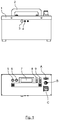
- Figure 2a, b shows a brake operation device with no internal energy storage which is similar to the device shown in Fig. 1a, b . Contrary to the device of Fig. 1a, b the device of Fig. 2a, b has a dedicated power input connector 10 for connecting an external energy source. Otherwise the devices of both figures are equal.
Landscapes
- Engineering & Computer Science (AREA)
- Transportation (AREA)
- Mechanical Engineering (AREA)
- Regulating Braking Force (AREA)
- Valves And Accessory Devices For Braking Systems (AREA)
Abstract
Description
- The invention relates to a brake operation device for a vehicle. Today, electro-pneumatic brake actuators are commonly used in commercial vehicles. In most cases, these brake actuators use a pneumatic energy source via pneumatic cylinders in order to realize the actuation of both the service brake and the parking brake. The parking brake function is realized by using a separate brake actuator that can be operated independently of the service brake actuator. The design of a spring based parking brake actuator allows a single brake actuation to be achieved even without compressed air as the energy source for the actuation. In the event of a pressure loss in the brake system, a pre-tensioned spring in the parking brake chamber provides sufficient braking energy to stop the vehicle or keep it stationary. To make the vehicle towable if there is no compressed air supply on board the vehicle, the parking brake actuation must be released. In combined electro-pneumatic brake chambers, this release can be carried out with a threaded tool such as a threaded shaft. The threaded shaft projects outwards from the spring brake chamber and is accessible to an operator. The brake can be released by turning the shaft with an ordinary wrench.
- In the future, electromechanical brake actuation will become more and more common. For these brakes, too, the requirement for external release capability should be met. In the event of a malfunction, e.g. if the parking brakes are applied and cannot be released on the normal operating route, a brake release solution is required to make the vehicle towable. Due to the complexity of the electro-mechanical brake cylinders, external brake release requires a special tool to release the parking brakes.
- It is the object of the present invention to provide a brake operation device for a vehicle that can be used for operating a parking brake in emergency cases.
- The object is achieved by a brake operation device for a vehicle comprising the features of
claim 1. Embodiments of the invention are described in the dependent claims. - The brake operation device comprises a control module configured to control a brake of the vehicle, a connector connected to the control module for providing a control signal from the control module for controlling the brake, an interface connected to the control module for receiving a user input to the control module; and a display for displaying a mode of operation of the device. The device may have a housing for accommodating the device components.
- The device is capable for a use with electromechanical brakes of vehicles and can be embodied as a standalone device for operating a parking brake especially in emergency cases. The device can be directly connected to the wheel brake actuator of a vehicle via cables, such as power supply and control cables. The control module of the device can operate either a single wheel-end or multiple wheel-ends of the vehicle at the same time, by providing proper communication with the wheel brake actuators regardless if those are integrated in the wheel-ends or mounted separately elsewhere. Besides parking brake application and release and diagnostics of the wheel-ends the device is capable to perform a service brake operation as well. To operate the wheel-ends via the device the overall brake system is not required to be fully functional but at least the corresponding wheel brake.
- According to an embodiment the control module of the device is configured to communicate with at least one module of at least one electro-mechanical brake actuator of the brake. The communication may include the transmission and receipt of messages and commands.
- According to another embodiment the device comprises a power supply configured to be connected to the brake to supply a brake actuator of the brake with power. Hence, a brake of a vehicle can be released on a road remote from a fixed power supply even if power from the vehicle is not available.
- According to yet another embodiment the device comprises a plug for an external power supply, the external power supply supplying power to at least one of the device and a brake actuator of the brake. This makes use of an external battery such as the battery of the vehicle possible to operate the brake, if the electromechanical brake system of the vehicle is not usable.
- According to an embodiment the device comprises a memory storing one or more modes of operation from the group comprising a service brake operation mode, a parking brake operation mode, a diagnostics mode, a trouble codes delete mode, and other operation programs.
- According to still another embodiment the device comprises a mode switch configured to switch operation of the device between multiple modes of operation from the group including a service brake operation mode, a parking brake operation mode, a diagnostics mode, and a trouble codes delete mode.
- According to still another embodiment the device comprises an output device such as a display or a speaker for outputting or showing an indication of a mode of operation of the device.
- According to still another embodiment the device comprises an interface device for receiving a user input. The interface device can be for example a switch, a touch display, a microphone, a keyboard or a microphone or a combination thereof.
- According to still another embodiment the device is further configured to provide a wake-up signal to the brake. For some brakes sending of a wake-up signal may be necessary, before a communication between the device and the brake actuator or the brake is possible.
- According to the invention also a computer-implemented method for controlling a brake of a vehicle is provided, wherein the method comprises connecting a brake operation device to a brake actuator of the vehicle; on the brake operation device, selecting an operation mode of the brake operation device; the brake operation device sending a wake-up signal to the brake actuator; and the brake operation device sending a control signal to the brake actuator according to the selected mode, the control signal releasing the brake.
- Further characteristics, features and advantages of the invention will result from the following description of an embodiment with reference to the annexed drawing in which:
- Fig. 1a, b
- shows a schematic view of an embodiment of the emergency brake operating device with internal energy storage and supply in a side view (
Fig. 1a ) and from the top (Fig. 1b ); and - Fig. 2a, b
- shows a schematic view of another embodiment of the emergency brake operating device for use with an external energy source in a side view (
Fig. 2a ) and the top (Fig. 2b ). - Embodiments of the brake operating device according to the invention are described. According to a first embodiment the brake operating device is implemented as a standalone apparatus with a
housing 1 which accommodates a control module (not shown) and an energy storage such as a rechargeable battery (not shown). Ahandle 2 is mounted on the device to make it easily movable. For charging the internal energy storage a chargingfuse 3 and charging plug-inconnectors 4 are provided. - On the housing 1 a power output connector C and a control output connector B are mounted for a power and control connection with a wheel brake of a vehicle, respectively. Inside the device the control module is connected with the control output connector B. The brake operation device also has an additional external connector that permits connection of a computer for monitoring the operation of the device. The additional external connector is also connected to the control module. The control module may include a microprocessor or other IC.
- Operation of the device can be such that the device in an emergency case in which a vehicle with locked brakes needs to be towed is connected to one or more brakes of the vehicle. In particular, a communication cable is connected between the control output connector B and the corresponding plug at the brake or brake actuator of the vehicle. Also a power cable can be connected between the power output C and a power supply plug of the vehicle, if power supply to the brake or brake actuator is necessary.
- Actuation of the brake starts with an activation on the power output C by a user interface such as
switch 8. The wake-up of the wheel brake is triggered by another user interface such asignition switch 9. Then an appropriate operation mode of the device is selected. The operation mode change is handled by another user interface such as "Mode"button 5 which is connected to the control module. The operation mode can be one of the following modes: "service brake operation mode", "parking brake operation mode", "diagnostics mode", and "trouble codes delete mode". For activation of a brake, when the brake needs to be released without actuation of the brake through the vehicle, the appropriate mode of operation is the "parking brake operation mode". - Inside a mode, the intended activity can be performed by pressing the "Execute"
button 6 that sends a corresponding signal to the control module which then conducts the operation of the brake of the vehicle automatically by sending respective control signals to the brake. At least some of the processes conducted by the device and the bake can be tracked on thedisplay 7 of the emergency operation device. Once the brake has been released the device can be switched off and removed. -
Figure 2a, b shows a brake operation device with no internal energy storage which is similar to the device shown inFig. 1a, b . Contrary to the device ofFig. 1a, b the device ofFig. 2a, b has a dedicatedpower input connector 10 for connecting an external energy source. Otherwise the devices of both figures are equal. - Many modifications can be performed on the devices without leaving the scope of the invention.
-
- 1
- housing
- 2
- handle
- 3
- charging fuse
- 4
- charging plug-in connectors
- 5
- Mode button
- 6
- Execute button
- 7
- display
- 8
- switch
- 9
- ignition switch
Claims (7)
- A brake operation device for actuating a brake of a vehicle, comprising:a control module configured to control a brake of the vehicle;a connector (B) connected to the control module for outputting a control signal from the control module for controlling the brake;an interface (5, 6, 8, 9) connected to the control module for receiving a user input to the control module; anda display (7) for displaying a mode of operation of the device.
- The brake operation device according to claim 1, wherein the control module is configured to communicate with at least one module of at least one electro-mechanical brake actuator of the brake.
- The brake operation device according to claim 1 or 2, further comprising a power supply (C) configured to be connected to the brake to supply a brake actuator of the brake with power.
- The brake operation device according to one of claims 1 to 3, further comprising a plug (10) for an external power supply, the external power supply supplying power to at least one of the device and a brake actuator of the brake.
- The brake operation device according to one of claims 1 to 4, further comprising a mode switch (5) configured to switch operation of the device between multiple modes of operation of the group including one or more of a service brake operation mode, a parking brake operation mode, a diagnostics mode, and a trouble codes delete mode.
- The brake operation device according to one of claims 1 to 5, wherein the device is further configured to provide a wake-up signal to the brake.
- A computer-implemented method for controlling a brake of a vehicle, the method comprising:connecting a brake operation device to a brake actuator of the vehicle;on the brake operation device, selecting an operation mode of the brake operation device;the brake operation device sending a wake-up signal to the brake actuator; andthe brake operation device sending a control signal to the brake actuator according to the selected mode, the control signal releasing the brake.
Priority Applications (1)
| Application Number | Priority Date | Filing Date | Title |
|---|---|---|---|
| EP20171695.8A EP3904170B1 (en) | 2020-04-28 | 2020-04-28 | Brake operation device |
Applications Claiming Priority (1)
| Application Number | Priority Date | Filing Date | Title |
|---|---|---|---|
| EP20171695.8A EP3904170B1 (en) | 2020-04-28 | 2020-04-28 | Brake operation device |
Publications (2)
| Publication Number | Publication Date |
|---|---|
| EP3904170A1 true EP3904170A1 (en) | 2021-11-03 |
| EP3904170B1 EP3904170B1 (en) | 2023-07-12 |
Family
ID=70470954
Family Applications (1)
| Application Number | Title | Priority Date | Filing Date |
|---|---|---|---|
| EP20171695.8A Active EP3904170B1 (en) | 2020-04-28 | 2020-04-28 | Brake operation device |
Country Status (1)
| Country | Link |
|---|---|
| EP (1) | EP3904170B1 (en) |
Citations (5)
| Publication number | Priority date | Publication date | Assignee | Title |
|---|---|---|---|---|
| US6286911B1 (en) * | 1996-09-13 | 2001-09-11 | New York Air Brake Corporation | Electronic brake controller with display |
| US20030221922A1 (en) * | 2002-02-26 | 2003-12-04 | Callow Robert W. | Automatic brake actuation system and method for vehicles |
| WO2007106014A1 (en) * | 2006-03-15 | 2007-09-20 | Volvo Lastvagnar Ab | A system for automatically actuating the parking brake on a vehicle |
| DE102008064077A1 (en) * | 2008-12-19 | 2010-07-01 | Wabco Gmbh | Actuating device and method for actuating such an actuator |
| CN206265032U (en) * | 2016-11-24 | 2017-06-20 | 郑州智辆电子科技有限公司 | Locomotive brake on-line monitoring system |
-
2020
- 2020-04-28 EP EP20171695.8A patent/EP3904170B1/en active Active
Patent Citations (5)
| Publication number | Priority date | Publication date | Assignee | Title |
|---|---|---|---|---|
| US6286911B1 (en) * | 1996-09-13 | 2001-09-11 | New York Air Brake Corporation | Electronic brake controller with display |
| US20030221922A1 (en) * | 2002-02-26 | 2003-12-04 | Callow Robert W. | Automatic brake actuation system and method for vehicles |
| WO2007106014A1 (en) * | 2006-03-15 | 2007-09-20 | Volvo Lastvagnar Ab | A system for automatically actuating the parking brake on a vehicle |
| DE102008064077A1 (en) * | 2008-12-19 | 2010-07-01 | Wabco Gmbh | Actuating device and method for actuating such an actuator |
| CN206265032U (en) * | 2016-11-24 | 2017-06-20 | 郑州智辆电子科技有限公司 | Locomotive brake on-line monitoring system |
Also Published As
| Publication number | Publication date |
|---|---|
| EP3904170B1 (en) | 2023-07-12 |
Similar Documents
| Publication | Publication Date | Title |
|---|---|---|
| US8794715B2 (en) | Electro-pneumatic latching valve system | |
| US20040012249A1 (en) | Electronic control air management with parking brake and trailer supply control | |
| CN105035056B (en) | Electrical spring energy storage device-parking brake | |
| US9162612B2 (en) | Brake testing device | |
| CN112714726B (en) | Brake system for a vehicle, vehicle and method for controlling a brake system | |
| US20050116533A1 (en) | Pressure medium-actuated brake system of a tractor-trailer combination | |
| US20080001470A1 (en) | Braking system | |
| CN112074439A (en) | Redundant braking system of heavy vehicle | |
| CA2314974A1 (en) | Air dryer reservoir module | |
| JPH0659823B2 (en) | Electrically controlled pressure medium brake | |
| CA2100684C (en) | Electro-pneumatic spring and service brake actuator | |
| US5242215A (en) | Interface for dissimilarly braked vehicles | |
| CN114728643A (en) | Brake system for a motor vehicle and trailer air supply and control module | |
| US20240375627A1 (en) | Electropneumatic trailer parking-brake system, trailer, towing combination | |
| US9278678B2 (en) | Modular electronic brake valve for air brakes vehicles | |
| US6154035A (en) | Remote control fleet safety inspection system | |
| WO2023101723A1 (en) | An apparatus and method for controlling release of a parking brake | |
| EP3904170B1 (en) | Brake operation device | |
| US7821154B2 (en) | Device and method for controlling an electric parking brake of a utility vehicle | |
| US20040183364A1 (en) | Miniaturized dash valve system | |
| CN112135758A (en) | Electronic device for controlling an electro-pneumatic parking brake circuit, parking brake system of a vehicle and method for controlling an electro-pneumatic parking brake circuit | |
| US20050000763A1 (en) | Auxiliary device for releasing the parking brake during failing energy supply | |
| US20040083040A1 (en) | Vehicle data retrieval system | |
| CN118306167A (en) | Vehicle and method for immobilizing a vehicle | |
| US7334849B2 (en) | Electronic Control system for controlling the brakes fitted on a rail or light rail motive power unit |
Legal Events
| Date | Code | Title | Description |
|---|---|---|---|
| PUAI | Public reference made under article 153(3) epc to a published international application that has entered the european phase |
Free format text: ORIGINAL CODE: 0009012 |
|
| STAA | Information on the status of an ep patent application or granted ep patent |
Free format text: STATUS: THE APPLICATION HAS BEEN PUBLISHED |
|
| AK | Designated contracting states |
Kind code of ref document: A1 Designated state(s): AL AT BE BG CH CY CZ DE DK EE ES FI FR GB GR HR HU IE IS IT LI LT LU LV MC MK MT NL NO PL PT RO RS SE SI SK SM TR |
|
| B565 | Issuance of search results under rule 164(2) epc |
Effective date: 20200703 |
|
| STAA | Information on the status of an ep patent application or granted ep patent |
Free format text: STATUS: REQUEST FOR EXAMINATION WAS MADE |
|
| 17P | Request for examination filed |
Effective date: 20220503 |
|
| RBV | Designated contracting states (corrected) |
Designated state(s): AL AT BE BG CH CY CZ DE DK EE ES FI FR GB GR HR HU IE IS IT LI LT LU LV MC MK MT NL NO PL PT RO RS SE SI SK SM TR |
|
| STAA | Information on the status of an ep patent application or granted ep patent |
Free format text: STATUS: EXAMINATION IS IN PROGRESS |
|
| 17Q | First examination report despatched |
Effective date: 20220609 |
|
| GRAP | Despatch of communication of intention to grant a patent |
Free format text: ORIGINAL CODE: EPIDOSNIGR1 |
|
| STAA | Information on the status of an ep patent application or granted ep patent |
Free format text: STATUS: GRANT OF PATENT IS INTENDED |
|
| INTG | Intention to grant announced |
Effective date: 20230216 |
|
| GRAS | Grant fee paid |
Free format text: ORIGINAL CODE: EPIDOSNIGR3 |
|
| GRAA | (expected) grant |
Free format text: ORIGINAL CODE: 0009210 |
|
| STAA | Information on the status of an ep patent application or granted ep patent |
Free format text: STATUS: THE PATENT HAS BEEN GRANTED |
|
| AK | Designated contracting states |
Kind code of ref document: B1 Designated state(s): AL AT BE BG CH CY CZ DE DK EE ES FI FR GB GR HR HU IE IS IT LI LT LU LV MC MK MT NL NO PL PT RO RS SE SI SK SM TR |
|
| REG | Reference to a national code |
Ref country code: CH Ref legal event code: EP |
|
| REG | Reference to a national code |
Ref country code: IE Ref legal event code: FG4D |
|
| REG | Reference to a national code |
Ref country code: DE Ref legal event code: R096 Ref document number: 602020013516 Country of ref document: DE |
|
| REG | Reference to a national code |
Ref country code: SE Ref legal event code: TRGR |
|
| REG | Reference to a national code |
Ref country code: LT Ref legal event code: MG9D |
|
| REG | Reference to a national code |
Ref country code: NL Ref legal event code: MP Effective date: 20230712 |
|
| REG | Reference to a national code |
Ref country code: AT Ref legal event code: MK05 Ref document number: 1586829 Country of ref document: AT Kind code of ref document: T Effective date: 20230712 |
|
| PG25 | Lapsed in a contracting state [announced via postgrant information from national office to epo] |
Ref country code: NL Free format text: LAPSE BECAUSE OF FAILURE TO SUBMIT A TRANSLATION OF THE DESCRIPTION OR TO PAY THE FEE WITHIN THE PRESCRIBED TIME-LIMIT Effective date: 20230712 |
|
| RAP4 | Party data changed (patent owner data changed or rights of a patent transferred) |
Owner name: KNORR-BREMSE SYSTEME FUER NUTZFAHRZEUGE GMBH |
|
| PG25 | Lapsed in a contracting state [announced via postgrant information from national office to epo] |
Ref country code: GR Free format text: LAPSE BECAUSE OF FAILURE TO SUBMIT A TRANSLATION OF THE DESCRIPTION OR TO PAY THE FEE WITHIN THE PRESCRIBED TIME-LIMIT Effective date: 20231013 |
|
| PG25 | Lapsed in a contracting state [announced via postgrant information from national office to epo] |
Ref country code: ES Free format text: LAPSE BECAUSE OF FAILURE TO SUBMIT A TRANSLATION OF THE DESCRIPTION OR TO PAY THE FEE WITHIN THE PRESCRIBED TIME-LIMIT Effective date: 20230712 |
|
| PG25 | Lapsed in a contracting state [announced via postgrant information from national office to epo] |
Ref country code: IS Free format text: LAPSE BECAUSE OF FAILURE TO SUBMIT A TRANSLATION OF THE DESCRIPTION OR TO PAY THE FEE WITHIN THE PRESCRIBED TIME-LIMIT Effective date: 20231112 |
|
| PG25 | Lapsed in a contracting state [announced via postgrant information from national office to epo] |
Ref country code: RS Free format text: LAPSE BECAUSE OF FAILURE TO SUBMIT A TRANSLATION OF THE DESCRIPTION OR TO PAY THE FEE WITHIN THE PRESCRIBED TIME-LIMIT Effective date: 20230712 Ref country code: PT Free format text: LAPSE BECAUSE OF FAILURE TO SUBMIT A TRANSLATION OF THE DESCRIPTION OR TO PAY THE FEE WITHIN THE PRESCRIBED TIME-LIMIT Effective date: 20231113 Ref country code: NO Free format text: LAPSE BECAUSE OF FAILURE TO SUBMIT A TRANSLATION OF THE DESCRIPTION OR TO PAY THE FEE WITHIN THE PRESCRIBED TIME-LIMIT Effective date: 20231012 Ref country code: LV Free format text: LAPSE BECAUSE OF FAILURE TO SUBMIT A TRANSLATION OF THE DESCRIPTION OR TO PAY THE FEE WITHIN THE PRESCRIBED TIME-LIMIT Effective date: 20230712 Ref country code: LT Free format text: LAPSE BECAUSE OF FAILURE TO SUBMIT A TRANSLATION OF THE DESCRIPTION OR TO PAY THE FEE WITHIN THE PRESCRIBED TIME-LIMIT Effective date: 20230712 Ref country code: IS Free format text: LAPSE BECAUSE OF FAILURE TO SUBMIT A TRANSLATION OF THE DESCRIPTION OR TO PAY THE FEE WITHIN THE PRESCRIBED TIME-LIMIT Effective date: 20231112 Ref country code: HR Free format text: LAPSE BECAUSE OF FAILURE TO SUBMIT A TRANSLATION OF THE DESCRIPTION OR TO PAY THE FEE WITHIN THE PRESCRIBED TIME-LIMIT Effective date: 20230712 Ref country code: GR Free format text: LAPSE BECAUSE OF FAILURE TO SUBMIT A TRANSLATION OF THE DESCRIPTION OR TO PAY THE FEE WITHIN THE PRESCRIBED TIME-LIMIT Effective date: 20231013 Ref country code: FI Free format text: LAPSE BECAUSE OF FAILURE TO SUBMIT A TRANSLATION OF THE DESCRIPTION OR TO PAY THE FEE WITHIN THE PRESCRIBED TIME-LIMIT Effective date: 20230712 Ref country code: ES Free format text: LAPSE BECAUSE OF FAILURE TO SUBMIT A TRANSLATION OF THE DESCRIPTION OR TO PAY THE FEE WITHIN THE PRESCRIBED TIME-LIMIT Effective date: 20230712 Ref country code: AT Free format text: LAPSE BECAUSE OF FAILURE TO SUBMIT A TRANSLATION OF THE DESCRIPTION OR TO PAY THE FEE WITHIN THE PRESCRIBED TIME-LIMIT Effective date: 20230712 |
|
| P01 | Opt-out of the competence of the unified patent court (upc) registered |
Effective date: 20240123 |
|
| PG25 | Lapsed in a contracting state [announced via postgrant information from national office to epo] |
Ref country code: PL Free format text: LAPSE BECAUSE OF FAILURE TO SUBMIT A TRANSLATION OF THE DESCRIPTION OR TO PAY THE FEE WITHIN THE PRESCRIBED TIME-LIMIT Effective date: 20230712 |
|
| REG | Reference to a national code |
Ref country code: DE Ref legal event code: R097 Ref document number: 602020013516 Country of ref document: DE |
|
| PG25 | Lapsed in a contracting state [announced via postgrant information from national office to epo] |
Ref country code: SM Free format text: LAPSE BECAUSE OF FAILURE TO SUBMIT A TRANSLATION OF THE DESCRIPTION OR TO PAY THE FEE WITHIN THE PRESCRIBED TIME-LIMIT Effective date: 20230712 Ref country code: RO Free format text: LAPSE BECAUSE OF FAILURE TO SUBMIT A TRANSLATION OF THE DESCRIPTION OR TO PAY THE FEE WITHIN THE PRESCRIBED TIME-LIMIT Effective date: 20230712 Ref country code: EE Free format text: LAPSE BECAUSE OF FAILURE TO SUBMIT A TRANSLATION OF THE DESCRIPTION OR TO PAY THE FEE WITHIN THE PRESCRIBED TIME-LIMIT Effective date: 20230712 Ref country code: DK Free format text: LAPSE BECAUSE OF FAILURE TO SUBMIT A TRANSLATION OF THE DESCRIPTION OR TO PAY THE FEE WITHIN THE PRESCRIBED TIME-LIMIT Effective date: 20230712 Ref country code: CZ Free format text: LAPSE BECAUSE OF FAILURE TO SUBMIT A TRANSLATION OF THE DESCRIPTION OR TO PAY THE FEE WITHIN THE PRESCRIBED TIME-LIMIT Effective date: 20230712 Ref country code: SK Free format text: LAPSE BECAUSE OF FAILURE TO SUBMIT A TRANSLATION OF THE DESCRIPTION OR TO PAY THE FEE WITHIN THE PRESCRIBED TIME-LIMIT Effective date: 20230712 |
|
| PLBE | No opposition filed within time limit |
Free format text: ORIGINAL CODE: 0009261 |
|
| STAA | Information on the status of an ep patent application or granted ep patent |
Free format text: STATUS: NO OPPOSITION FILED WITHIN TIME LIMIT |
|
| PG25 | Lapsed in a contracting state [announced via postgrant information from national office to epo] |
Ref country code: IT Free format text: LAPSE BECAUSE OF FAILURE TO SUBMIT A TRANSLATION OF THE DESCRIPTION OR TO PAY THE FEE WITHIN THE PRESCRIBED TIME-LIMIT Effective date: 20230712 |
|
| 26N | No opposition filed |
Effective date: 20240415 |
|
| PG25 | Lapsed in a contracting state [announced via postgrant information from national office to epo] |
Ref country code: SI Free format text: LAPSE BECAUSE OF FAILURE TO SUBMIT A TRANSLATION OF THE DESCRIPTION OR TO PAY THE FEE WITHIN THE PRESCRIBED TIME-LIMIT Effective date: 20230712 |
|
| REG | Reference to a national code |
Ref country code: DE Ref legal event code: R119 Ref document number: 602020013516 Country of ref document: DE |
|
| PG25 | Lapsed in a contracting state [announced via postgrant information from national office to epo] |
Ref country code: BG Free format text: LAPSE BECAUSE OF FAILURE TO SUBMIT A TRANSLATION OF THE DESCRIPTION OR TO PAY THE FEE WITHIN THE PRESCRIBED TIME-LIMIT Effective date: 20230712 |
|
| PG25 | Lapsed in a contracting state [announced via postgrant information from national office to epo] |
Ref country code: MC Free format text: LAPSE BECAUSE OF FAILURE TO SUBMIT A TRANSLATION OF THE DESCRIPTION OR TO PAY THE FEE WITHIN THE PRESCRIBED TIME-LIMIT Effective date: 20230712 |
|
| PG25 | Lapsed in a contracting state [announced via postgrant information from national office to epo] |
Ref country code: MC Free format text: LAPSE BECAUSE OF FAILURE TO SUBMIT A TRANSLATION OF THE DESCRIPTION OR TO PAY THE FEE WITHIN THE PRESCRIBED TIME-LIMIT Effective date: 20230712 Ref country code: BG Free format text: LAPSE BECAUSE OF FAILURE TO SUBMIT A TRANSLATION OF THE DESCRIPTION OR TO PAY THE FEE WITHIN THE PRESCRIBED TIME-LIMIT Effective date: 20230712 |
|
| REG | Reference to a national code |
Ref country code: CH Ref legal event code: PL |
|
| PG25 | Lapsed in a contracting state [announced via postgrant information from national office to epo] |
Ref country code: LU Free format text: LAPSE BECAUSE OF NON-PAYMENT OF DUE FEES Effective date: 20240428 |
|
| GBPC | Gb: european patent ceased through non-payment of renewal fee |
Effective date: 20240428 |
|
| REG | Reference to a national code |
Ref country code: BE Ref legal event code: MM Effective date: 20240430 |
|
| PG25 | Lapsed in a contracting state [announced via postgrant information from national office to epo] |
Ref country code: LU Free format text: LAPSE BECAUSE OF NON-PAYMENT OF DUE FEES Effective date: 20240428 |
|
| PG25 | Lapsed in a contracting state [announced via postgrant information from national office to epo] |
Ref country code: DE Free format text: LAPSE BECAUSE OF NON-PAYMENT OF DUE FEES Effective date: 20241105 |
|
| PG25 | Lapsed in a contracting state [announced via postgrant information from national office to epo] |
Ref country code: BE Free format text: LAPSE BECAUSE OF NON-PAYMENT OF DUE FEES Effective date: 20240430 |
|
| PG25 | Lapsed in a contracting state [announced via postgrant information from national office to epo] |
Ref country code: GB Free format text: LAPSE BECAUSE OF NON-PAYMENT OF DUE FEES Effective date: 20240428 |
|
| PG25 | Lapsed in a contracting state [announced via postgrant information from national office to epo] |
Ref country code: FR Free format text: LAPSE BECAUSE OF NON-PAYMENT OF DUE FEES Effective date: 20240430 |
|
| PG25 | Lapsed in a contracting state [announced via postgrant information from national office to epo] |
Ref country code: GB Free format text: LAPSE BECAUSE OF NON-PAYMENT OF DUE FEES Effective date: 20240428 Ref country code: FR Free format text: LAPSE BECAUSE OF NON-PAYMENT OF DUE FEES Effective date: 20240430 Ref country code: DE Free format text: LAPSE BECAUSE OF NON-PAYMENT OF DUE FEES Effective date: 20241105 Ref country code: BE Free format text: LAPSE BECAUSE OF NON-PAYMENT OF DUE FEES Effective date: 20240430 Ref country code: CH Free format text: LAPSE BECAUSE OF NON-PAYMENT OF DUE FEES Effective date: 20240430 |
|
| PG25 | Lapsed in a contracting state [announced via postgrant information from national office to epo] |
Ref country code: IE Free format text: LAPSE BECAUSE OF NON-PAYMENT OF DUE FEES Effective date: 20240428 |
|
| PGFP | Annual fee paid to national office [announced via postgrant information from national office to epo] |
Ref country code: SE Payment date: 20250424 Year of fee payment: 6 |
|
| PG25 | Lapsed in a contracting state [announced via postgrant information from national office to epo] |
Ref country code: CY Free format text: LAPSE BECAUSE OF FAILURE TO SUBMIT A TRANSLATION OF THE DESCRIPTION OR TO PAY THE FEE WITHIN THE PRESCRIBED TIME-LIMIT; INVALID AB INITIO Effective date: 20200428 |
|
| PG25 | Lapsed in a contracting state [announced via postgrant information from national office to epo] |
Ref country code: HU Free format text: LAPSE BECAUSE OF FAILURE TO SUBMIT A TRANSLATION OF THE DESCRIPTION OR TO PAY THE FEE WITHIN THE PRESCRIBED TIME-LIMIT; INVALID AB INITIO Effective date: 20200428 |