EP3904026A1 - Electric stapler, post-processing device, and image forming system - Google Patents
Electric stapler, post-processing device, and image forming system Download PDFInfo
- Publication number
- EP3904026A1 EP3904026A1 EP21170709.6A EP21170709A EP3904026A1 EP 3904026 A1 EP3904026 A1 EP 3904026A1 EP 21170709 A EP21170709 A EP 21170709A EP 3904026 A1 EP3904026 A1 EP 3904026A1
- Authority
- EP
- European Patent Office
- Prior art keywords
- paper bundle
- gripping
- clamp part
- wall portion
- electric stapler
- Prior art date
- Legal status (The legal status is an assumption and is not a legal conclusion. Google has not performed a legal analysis and makes no representation as to the accuracy of the status listed.)
- Granted
Links
Images




Classifications
-
- B—PERFORMING OPERATIONS; TRANSPORTING
- B25—HAND TOOLS; PORTABLE POWER-DRIVEN TOOLS; MANIPULATORS
- B25C—HAND-HELD NAILING OR STAPLING TOOLS; MANUALLY OPERATED PORTABLE STAPLING TOOLS
- B25C5/00—Manually operated portable stapling tools; Hand-held power-operated stapling tools; Staple feeding devices therefor
- B25C5/10—Driving means
- B25C5/15—Driving means operated by electric power
-
- B—PERFORMING OPERATIONS; TRANSPORTING
- B65—CONVEYING; PACKING; STORING; HANDLING THIN OR FILAMENTARY MATERIAL
- B65H—HANDLING THIN OR FILAMENTARY MATERIAL, e.g. SHEETS, WEBS, CABLES
- B65H37/00—Article or web delivery apparatus incorporating devices for performing specified auxiliary operations
- B65H37/04—Article or web delivery apparatus incorporating devices for performing specified auxiliary operations for securing together articles or webs, e.g. by adhesive, stitching or stapling
-
- B—PERFORMING OPERATIONS; TRANSPORTING
- B27—WORKING OR PRESERVING WOOD OR SIMILAR MATERIAL; NAILING OR STAPLING MACHINES IN GENERAL
- B27F—DOVETAILED WORK; TENONS; SLOTTING MACHINES FOR WOOD OR SIMILAR MATERIAL; NAILING OR STAPLING MACHINES
- B27F7/00—Nailing or stapling; Nailed or stapled work
- B27F7/17—Stapling machines
- B27F7/19—Stapling machines with provision for bending the ends of the staples on to the work
-
- B—PERFORMING OPERATIONS; TRANSPORTING
- B27—WORKING OR PRESERVING WOOD OR SIMILAR MATERIAL; NAILING OR STAPLING MACHINES IN GENERAL
- B27F—DOVETAILED WORK; TENONS; SLOTTING MACHINES FOR WOOD OR SIMILAR MATERIAL; NAILING OR STAPLING MACHINES
- B27F7/00—Nailing or stapling; Nailed or stapled work
- B27F7/17—Stapling machines
- B27F7/30—Driving means
- B27F7/36—Driving means operated by electric power
-
- B—PERFORMING OPERATIONS; TRANSPORTING
- B31—MAKING ARTICLES OF PAPER, CARDBOARD OR MATERIAL WORKED IN A MANNER ANALOGOUS TO PAPER; WORKING PAPER, CARDBOARD OR MATERIAL WORKED IN A MANNER ANALOGOUS TO PAPER
- B31F—MECHANICAL WORKING OR DEFORMATION OF PAPER, CARDBOARD OR MATERIAL WORKED IN A MANNER ANALOGOUS TO PAPER
- B31F5/00—Attaching together sheets, strips or webs; Reinforcing edges
- B31F5/001—Attaching together sheets, strips or webs; Reinforcing edges by stapling or riveting
-
- B—PERFORMING OPERATIONS; TRANSPORTING
- B41—PRINTING; LINING MACHINES; TYPEWRITERS; STAMPS
- B41L—APPARATUS OR DEVICES FOR MANIFOLDING, DUPLICATING OR PRINTING FOR OFFICE OR OTHER COMMERCIAL PURPOSES; ADDRESSING MACHINES OR LIKE SERIES-PRINTING MACHINES
- B41L43/00—Auxiliary folding, collecting, or depositing of sheets or webs
- B41L43/10—Collecting
- B41L43/12—Collecting and stapling
-
- B—PERFORMING OPERATIONS; TRANSPORTING
- B42—BOOKBINDING; ALBUMS; FILES; SPECIAL PRINTED MATTER
- B42C—BOOKBINDING
- B42C1/00—Collating or gathering sheets combined with processes for permanently attaching together sheets or signatures or for interposing inserts
- B42C1/12—Machines for both collating or gathering and permanently attaching together the sheets or signatures
-
- B—PERFORMING OPERATIONS; TRANSPORTING
- B65—CONVEYING; PACKING; STORING; HANDLING THIN OR FILAMENTARY MATERIAL
- B65H—HANDLING THIN OR FILAMENTARY MATERIAL, e.g. SHEETS, WEBS, CABLES
- B65H2408/00—Specific machines
- B65H2408/10—Specific machines for handling sheet(s)
- B65H2408/12—Specific machines for handling sheet(s) stapler arrangement
- B65H2408/121—Specific machines for handling sheet(s) stapler arrangement stationary stapler
-
- B—PERFORMING OPERATIONS; TRANSPORTING
- B65—CONVEYING; PACKING; STORING; HANDLING THIN OR FILAMENTARY MATERIAL
- B65H—HANDLING THIN OR FILAMENTARY MATERIAL, e.g. SHEETS, WEBS, CABLES
- B65H2801/00—Application field
- B65H2801/03—Image reproduction devices
- B65H2801/06—Office-type machines, e.g. photocopiers
-
- G—PHYSICS
- G03—PHOTOGRAPHY; CINEMATOGRAPHY; ANALOGOUS TECHNIQUES USING WAVES OTHER THAN OPTICAL WAVES; ELECTROGRAPHY; HOLOGRAPHY
- G03G—ELECTROGRAPHY; ELECTROPHOTOGRAPHY; MAGNETOGRAPHY
- G03G2215/00—Apparatus for electrophotographic processes
- G03G2215/00362—Apparatus for electrophotographic processes relating to the copy medium handling
- G03G2215/00789—Adding properties or qualities to the copy medium
- G03G2215/00822—Binder, e.g. glueing device
-
- G—PHYSICS
- G03—PHOTOGRAPHY; CINEMATOGRAPHY; ANALOGOUS TECHNIQUES USING WAVES OTHER THAN OPTICAL WAVES; ELECTROGRAPHY; HOLOGRAPHY
- G03G—ELECTROGRAPHY; ELECTROPHOTOGRAPHY; MAGNETOGRAPHY
- G03G2215/00—Apparatus for electrophotographic processes
- G03G2215/00362—Apparatus for electrophotographic processes relating to the copy medium handling
- G03G2215/00789—Adding properties or qualities to the copy medium
- G03G2215/00822—Binder, e.g. glueing device
- G03G2215/00827—Stapler
-
- G—PHYSICS
- G03—PHOTOGRAPHY; CINEMATOGRAPHY; ANALOGOUS TECHNIQUES USING WAVES OTHER THAN OPTICAL WAVES; ELECTROGRAPHY; HOLOGRAPHY
- G03G—ELECTROGRAPHY; ELECTROPHOTOGRAPHY; MAGNETOGRAPHY
- G03G2215/00—Apparatus for electrophotographic processes
- G03G2215/00362—Apparatus for electrophotographic processes relating to the copy medium handling
- G03G2215/00789—Adding properties or qualities to the copy medium
- G03G2215/00822—Binder, e.g. glueing device
- G03G2215/00848—Details of binding device
Definitions
- the present invention relates to an electric stapler that binds a paper bundle with a staple, a post-processing device on which the electric stapler is mounted, and an image forming system including the post-processing device.
- the post-processing device may be equipped with an electric stapler that binds a paper bundle with a staple.
- the electric stapler includes a home position sensor that detects a rotational position of a gear driven by a motor, and is configured such that an output of the home position sensor becomes a predetermined output after a clamping process of clamping a paper bundle, a penetrating process of causing a staple to penetrate the paper bundle, and a clinching process of bending the staple are completed and clamping is released.
- the bound paper bundle being dischargeable is detected based on the output of the home position sensor, and is output to the post-processing device.
- the post-processing device when a notification that the bound paper bundle is being dischargeable is received from the electric stapler, discharge processing of the paper bundle is performed.
- Patent Literature 1 JP-A-2011-201662
- the paper bundle can be discharged.
- discharge is not performed until an output signal from the home position sensor is received even though the paper bundle is actually in a dischargeable state, and therefore, unnecessary waiting is caused in a period from when the dischargeable state is established to when the output signal from the home position sensor is received.
- the time until completion of the clinching process varies depending on magnitude of a load (for example, whether the paper bundle is thin or thick). Accordingly, in a method of determining a timing at which the paper bundle can be discharged with the passage of time, when the timing at which the paper bundle can be discharged with the passage of time is determined on a basis of a case where the load is small (for example, a case where the paper bundle is thin), there is a possibility that the discharge of the paper bundle is started before the completion of the clinching process in a case where the load is large. In such a case, the post-processing device starts discharging the paper bundle although the stapler clamps the paper bundle, which is a main cause of a jam or a mechanical failure.
- an electric stapler including: a clamp part that is configured to include a first wall portion and a second wall portion facing each other with a predetermined gap therebetween, in which the first wall portion is movable in directions of approaching and separating from the second wall portion, and that grips a paper bundle inserted between the first wall portion and the second wall portion by moving the first wall portion in the direction of approaching the second wall portion; a penetration part that causes a staple to penetrate the paper bundle gripped by the clamp part; a clinch part that bends the staple penetrating the paper bundle to bind the paper bundle; a gripping release detection unit that detects that the paper bundle is released from gripping after the first wall portion moves in the direction of separating from the second wall portion from a state where the paper bundle is gripped by the clamp part; and an output unit that, after it is detected that the paper bundle is released from gripping of the clamp part, outputs a gripping release signal indicating that the paper bundle
- a gripping release signal is output to the outside, and processing based on the gripping release signal is performed.
- a gripping release signal is output when it is detected that a paper bundle is actually released from gripping of a clamp part, it is possible to detect a suitable discharge timing, preferably an optimum discharge timing, of the paper bundle.
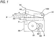
- Fig. 1 is a side sectional view illustrating an example of an electric stapler according to an embodiment.
- An electric stapler 1A includes a clamp part 2 that clamps a paper bundle P, a penetration part 3 that causes a staple 10 to penetrate the paper bundle P, and a clinch part 4 that bends the staple 10 penetrating the paper bundle P to bind the paper bundle P.
- the electric stapler 1A includes a motor 5 that drives the clamp part 2, the penetration part 3, and the clinch part 4.
- the electric stapler 1A includes a striking unit 30 in which the penetration part 3 is provided, and a binding unit 40 in which the clinch part 4 is provided.
- the clamp part 2 includes a first wall portion 21 and a second wall portion 22 that face each other with a predetermined gap therebetween.
- the first wall portion 21 is formed at a portion facing the striking unit 30 of the binding unit 40.
- the second wall portion 22 is formed at a portion facing the binding unit 40 of the striking unit 30.
- the binding unit 40 moves in directions approaching and separating from the striking unit 30 by a rotating operation with a shaft 31 serving as a fulcrum.
- the first wall portion 21 moves in directions of approaching and separating from the second wall portion 22.
- the clamp part 2 sandwiches the paper bundle P between the first wall portion 21 and the second wall portion 22 when the first wall portion 21 is moved in a direction of approaching the second wall portion 22.
- the paper bundle P sandwiched between the first wall portion 21 and the second wall portion 22 is released.
- a cartridge 100 in which the staples 10 are accommodated in a connected state, is detachably attached to the striking unit 30.
- the penetration part 3 separates one leading staple of the staples 10 accommodated in the cartridge 100, and strikes the staple 10 toward the paper bundle P sandwiched between the first wall portion 21 and the second wall portion 22 to penetrate the paper bundle P.
- the penetration part 3 may include a movable part movable between a first position and a second position. The second position is apart from the first position in the direction orthogonal to a surface of the paper bundle.
- the striking unit 30 includes a mechanism that feeds the staple 10 accommodated in the cartridge 100 to a position where the staple 10 can be struck by the penetration part 3.
- the striking unit 30 includes a mechanism that forms the staple 10 into a U shape, with the staples in a form of being connected in a sheet shape and accommodated in the cartridge 100 for supply.
- the clinch part 4 bends the staple 10 penetrating the paper bundle P sandwiched between the first wall portion 21 and the second wall portion 22 in a predetermined direction.
- the binding unit 40 may include a mechanism that cuts legs of the staple 10 penetrating the paper bundle P.
- the clinch part 4 may include a contact surface which comes into contact with the staple 10 to bend the staple 10.
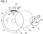
- Fig. 2 is a side sectional view illustrating an example of a driving unit.
- the electric stapler 1A includes a driving unit 50 that transmits rotation of the motor 5 to the clamp part 2, the penetration part 3, and the clinch part 4.
- the driving unit 50 includes a driven gear 51 that transmits the rotation of the motor 5 to the clamp part 2, the penetration part 3, and the clinch part 4, and an intermediate gear 52 that transmits the rotation of the motor 5 to the driven gear 51.
- the driving unit 50 rotation of a motor shaft 5a of the motor 5 is transmitted to the driven gear 51 via the intermediate gear 52, and the driven gear 51 rotates.
- the driving unit 50 moves the binding unit 40 in directions of approaching and separating from the striking unit 30, and opens and closes the clamp part 2.
- the driving unit 50 drives the penetration part 3 and the clinch part 4 by transmitting the rotation of the driven gear 51 to a cam or the like (not illustrated).
- the binding unit 40 moves in a direction of approaching the striking unit 30, and the paper bundle P is clamped by the clamp part 2.
- the staples 10 accommodated in the cartridge 100 are fed out, and one leading staple 10 of the fed-out staples 10 is struck by the penetration part 3 toward the paper bundle P clamped by the clamp part 2 to penetrate the paper bundle P.
- the staple 10 penetrating the paper bundle P is bent by the clinch part 4 by, and in the operation of the driven gear 51 further rotating in the one direction, the binding unit 40 is moved in a direction of separating from the striking unit 30, and the clamping of the paper bundle P by the clamp part 2 is released.
- the electric stapler 1A performs a clamping process of clamping the paper bundle P with the clamp part 2, a penetrating process of striking the staple 10 into the paper bundle P with the penetration part 3, a clinching process of bending the staple 10 with the clinch part 4, and a returning process of releasing the paper bundle P clamped by the clamp part 2.
- a position along a rotation direction of the motor shaft 5a of the motor 5 is referred to as a rotational position of the motor 5.
- a position along a rotation direction of the driven gear 51 is referred to as a rotational position of the driven gear 51.
- the driven gear 51 meshes with the intermediate gear 52 and the intermediate gear 52 meshes with a gear (not illustrated) of the motor shaft 5a, and thus a rotational speed of the driven gear 51 is a value obtained by reducing a rotational speed of the motor 5 at a predetermined reduction ratio. Accordingly, a rotational position and a rotation amount of the driven gear 51 are proportional to a rotational position and a rotation amount of the motor 5.
- a home position sensor 101 that detects a rotational position of the driven gear 51 is provided for the rotational positions of the motor 5 and the driven gear 51.
- the rotation amount of the motor 5 is detected based on an output of a magnetic sensor 102 (rotation amount detection unit) used for detecting a position of a rotor (not illustrated) of the motor 5 that is configured with a brushless motor.
- the home position sensor 101 detects the rotational position of the driven gear 51 in order to cause the clamp part 2, the penetration part 3, and the clinch part 4 to standby at a predetermined home position.
- a stop target range SE is set to a predetermined range in a circumferential direction of the driven gear 51 in order to stop the rotational position of the driven gear 51 at a predetermined position when stopping driving of the motor 5 or in order to detect a timing for discharging the paper bundle P.
- the electric stapler 1A is configured such that an output of the home position sensor 101 changes from 0 (OFF) to 1 (ON), for example, when a stop target range start-point position PS, which is a start-point of the stop target range SE, reaches a detection position P101 of the home position sensor 101 with respect to rotation of the driven gear 51 in a forward direction indicated by an arrow F.
- the electric stapler 1A is configured such that the output of the home position sensor 101 changes from 1 (ON) to 0 (OFF), for example, when a stop target range end-point position PE, which is an end-point of the stop target range SE, reaches the detection position P101 of the home position sensor 101 with respect to the rotation of the driven gear 51 in the forward direction indicated by the arrow F.
- the electric stapler 1A is configured such that the home position sensor 101 can detect the stop target range SE of the driven gear 51.
- the stop target position P1 of the driven gear 51 is set within the stop target range SE.
- the stop target position P1 of the driven gear 51 is located at the detection position P101 of the home position sensor 101, the clamp part 2, the penetration part 3, and the clinch part 4 are located at respective home positions.
- the stop target range end-point position PE reaches the detection position P101 of the home position sensor 101.
- a predetermined range from the stop target range end-point position PE is set as a clamp range CL in which clamping of the paper bundle P by the clamp part 2 is performed in the clamping process.
- a penetration range TH is set in which the staple 10 is struck into the paper bundle P by the penetration part 3 in the penetrating process.
- a clinch range of the clinching process is set, and following the clinch range, a clamp release range of the returning process is set, met by the stop target range start-point position PS.
- Fig. 3 is a block diagram illustrating an example of control functions of the stapler.
- the electric stapler 1A includes a control unit (controller) 110 that controls the motor 5 and a motor driving unit (a motor driving circuit) 111 that drives the motor 5.
- control unit controller 110 that controls the motor 5
- motor driving unit a motor driving circuit
- the control unit 110 (implementing a gripping release detection unit, a paper bundle thickness information acquisition unit, a paper sheet number acquisition unit, an output unit, a load fluctuation detection unit, and a thickness estimation unit) includes a CPU 110a, and executes the binding processing of the electric stapler 1A by executing a program stored in a storage unit 110b.
- the motor driving unit 111 drives the motor 5 by known PWM control based on position information of a rotor (not illustrated) output from the magnetic sensor 102.
- the control unit 110 detects the timing, at which the paper bundle P can be discharged, based on the rotational position of the driven gear 51 detected by the home position sensor 101 and the rotation amount of the motor 5 detected by the magnetic sensor 102, that is, the rotation amount of the driven gear 51.
- FIG. 4 is a configuration diagram illustrating an overview of an image forming system according to the present embodiment.
- An image forming system 500A of the present embodiment includes an image forming device 501A and a post-processing device 502A that is capable of performing at least one type of processing.
- the image forming device 501A forms and outputs an image on a sheet of paper fed from a paper feeding portion (not illustrated) inside or outside the device.
- the image forming device 501A forms an image on a sheet of paper by forming an electrostatic latent image by scanning exposure, developing the electrostatic latent image with toner, transferring the toner to the sheet of paper, and fixing the toner.
- the post-processing device 502A includes the above-described electric stapler 1A in a binding part 503A.
- the CPU 110a of the control unit 110 illustrated in Fig. 3 is connected to a control unit (not illustrated) of the post-processing device 502A and a control unit (not illustrated) of the image forming device 501A.
- the image forming device 501A instructs the post-processing device 502A to perform the binding processing when performing the binding processing of binding the paper bundle P is selected by an operation part (not illustrated).
- the post-processing device 502A performs paper alignment processing of aligning a predetermined number of sheets of paper output from the image forming device 501A, and outputs a binding command to the stapler 1A when the paper alignment processing is completed.
- the post-processing device 502A performs discharge processing of the bound paper bundle P.
- the paper alignment processing is performed to align the paper to be bound next.
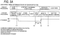
- Fig. 5 is a time chart illustrating an operation example of an electric stapler in the related art. A specific example of the problem described in the section of "Technical Problem" will be described.
- Fig. 5A illustrates an example in which a timing at which the paper bundle P can be discharged is determined based on ON-OFF-ON detection of the home position sensor. Note that Fig. 1 and the like are used for the configuration of the electric stapler in the related art.
- the electric stapler 1A is configured such that after the home position sensor 101 detects the stop target range end-point position PE of the driven gear 51 illustrated in Fig. 2 (detection of HP sensor OFF), the clamping process, the penetrating process, and the clinching process are completed, and after the clamp part 2 is opened, the home position sensor 101 detects the stop target range start-point position PS of the driven gear 51 (detection of HP sensor ON).
- Fig. 5B illustrates an example in which a timing at which the paper bundle P can be discharged is determined with the passage of time since detection of the home position sensor OFF.
- a force for causing the staple 10 to penetrate the paper bundle P is smaller than that in a case where the load is large. Accordingly, a rotational speed of the motor 5 in stapler processing is increased.
- the force for causing the staple 10 to penetrate the paper bundle P is larger than that in the case where the load is small. Accordingly, the rotational speed of the motor 5 in the stapler processing is reduced.
- time from when the home position sensor 101 detects the stop target range end-point position PE of the driven gear 51 (detection of HP sensor OFF) to when the clinching process is completed varies depending on the magnitude of the load.
- the time from when the home position sensor 101 detects the stop target range end-point position PE of the driven gear 51 (detection of HP sensor OFF) to when the clinching process is completed is shorter in the case where the load is small than in the case where the load is large.
- the post-processing device starts discharging the paper bundle although the stapler clamps the paper bundle, which is a main cause of a jam or a mechanical failure.
- Figs. 6A and 6B are time charts illustrating a first operation example of the electric stapler according to the present embodiment, in which Fig. 6A illustrates a case where the load is small due to a small number of sheets of paper to be bound or the like, and Fig. 6B illustrates a case where the load is large due to a large number of sheets of paper to be bound or the like.
- the post-processing device 502A illustrated in Fig. 4 outputs a binding command to the stapler 1A.
- the control unit 110 of the stapler 1A does not drive the motor 5 and does not execute the stapler processing.
- the control unit 110 rotates the motor 5 forward to rotate the driven gear 51 illustrated in Fig. 2 in one direction indicated by the arrow F.
- the control unit 110 starts counting the number of pulses from the magnetic sensor 102.
- rotation amount information D1 is acquired based on position information output from the magnetic sensor 102.
- the rotation amount information D1 is the number of pulses obtained by counting the number of pulses generated based on the position information accompanying the rotation of the motor 5.
- a rotation amount (the number of pulses) of the motor 5 in a period from when the home position sensor 101 detects the stop target range end-point position PE of the driven gear 51 to when the paper bundle P can be discharged is determined in advance.
- the rotation amount is, for example, a rotation amount of the motor 5 at the time when clamping of the paper bundle P with a maximum number of sheets that can be bound in the electric stapler 1A can be released.
- the rotation amount of the motor 5 in the period from when the stop target range end-point position PE of the driven gear 51 is detected to when the paper bundle P can be discharged is referred to as a discharge-possible rotation amount D2, during which the clinching process is completed and the clamp part 2 is opened.
- the discharge-possible rotation amount D2 is set before the home position sensor is turned ON.
- the control unit 110 determines that the paper bundle P can be released from the clamping (gripping), and outputs a binding completion notification (gripping release signal) to the post-processing device 502A correspondingly to counting completion at (3) in Figs. 6A and 6B .
- the electric stapler 1A may include an interface for outputting the signal.
- the rotation amount of the motor 5, that is, the number of pulses at which the paper bundle P can be discharged is constant. But as indicated by (2)-(3) of Fig.
- the post-processing device 502A When the binding completion notification from the stapler 1A is received, the post-processing device 502A performs the discharge processing of the paper bundle P. In a case where there is paper to be bound next when the discharge processing of the paper bundle P is completed, the paper alignment processing is performed to align the paper to be bound next.
- the control unit 110 When the home position sensor 101 detects the stop target range start-point position PS of the driven gear 51, that is, the HP sensor ON is detected at (4) in Figs. 6A and 6B , the control unit 110 performs braking control of stopping the driving of the motor 5. This braking control is also referred to as braking or applying a brake.
- the control unit 110 stops the rotation of the motor 5 correspondingly to motor stop at (5) of Figs. 6A and 6B so as to locate the stop target position P1 of the driven gear 51 at the detection position P101 of the home position sensor 101. Accordingly, the clamp part 2, the penetration part 3, and the clinch part 4 stop at respective home positions.
- the timing, at which the clamp part 2 is opened to allow discharging of the paper bundle P can be discharged after the clinching process is completed is determined based on the rotation amount information acquired based on the position information output from the magnetic sensor 102, so that an optimum discharge timing of the paper bundle can be detected even when the load is changed. Accordingly, by the ON-OFF-ON detection of the home position sensor, it is possible to reduce unnecessary waiting, which is a problem in the related art in which the timing at which the paper bundle P can be discharged is determined.
- Factors of load fluctuation include a thickness of the paper bundle, a paper type, humidity of paper, temperature of the motor, voltage fluctuation, individual mechanical difference, mechanical aging degradation, and the like.
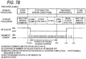
- Fig. 7 is a time chart illustrating a second operation example of the electric stapler according to the present embodiment.
- information specifying a thickness of the paper bundle P is acquired from the image forming device 501A or the post-processing device 502A, and a timing of discharging the paper bundle P is determined according to the thickness of the paper bundle P.
- Fig. 7A illustrates a case where the thickness of the paper bundle is large due to a large number of sheets of paper to be bound and the like
- Fig. 7B illustrates a case where the thickness of the paper bundle is small due to a small number of sheets of paper to be bound and the like.
- the control unit 110 calculates, based on the thickness information, the discharge-possible rotation amount D3 (which will be described later) at which the clamping of the paper bundle P is released.
- the thickness information of the paper bundle P includes information of a thickness of the paper bundle P, the number of sheets of paper to be bound, paper quality, basis weight, and the like.
- the post-processing device 502A outputs the thickness information of the paper bundle P to the staple 1A, and outputs a binding command to the stapler 1A when paper alignment processing is completed. Until the paper alignment processing is completed and the binding command is issued in finisher processing in the post-processing device 502A, the control unit 110 of the stapler 1A does not drive the motor 5 and does not execute the stapler processing.
- the control unit 110 rotates the motor 5 forward to rotate the driven gear 51 illustrated in Fig. 2 in one direction indicated by the arrow F.
- the control unit 110 starts counting the number of pulses and acquires rotation amount information D1 based on position information output from the magnetic sensor 102.
- the rotation amount information D1 is the number of pulses obtained by counting the number of pulses generated based on the position information accompanying the rotation of the motor 5.
- a rotation amount (the number of pulses) of the motor 5 in a period from when the home position sensor 101 detects the stop target range end-point position PE of the driven gear 51 to when the paper bundle P can be discharged is determined according to the thickness of the paper bundle P to be bound, during which the clamping process, the penetrating process, and the clinching process are completed and the clamp part 2 is opened.
- the rotation amount of the motor 5 corresponding to the thickness information of the paper bundle and in the period from when the stop target range end-point position PE of the driven gear 51 is detected to when the paper bundle P can be discharged is referred to as a discharge-possible rotation amount D3, during which the clinching process is completed and the clamp part 2 is opened.
- the control unit 110 sets the discharge-possible rotation amount D3 corresponding to the thickness information of the paper bundle.
- the control unit 110 determines that the paper bundle P can be released from the clamping (gripping), and outputs a binding completion notification to the post-processing device 502A correspondingly to counting completion at (3) in Figs. 7A and 7B .
- the post-processing device 502A When the binding completion notification from the stapler 1A is received, the post-processing device 502A performs the discharge processing of the paper bundle P. In a case where there is paper to be bound next when the discharge processing of the paper bundle P is completed, the paper alignment processing is performed to align the paper to be bound next.
- the control unit 110 performs braking control of stopping the driving of the motor 5.
- the control unit 110 stops the rotation of the motor 5 correspondingly to motor stop at (5) of Figs. 7A and 7B so as to locate the stop target position P1 of the driven gear 51 at the detection position P101 of the home position sensor 101. Accordingly, the clamp part 2, the penetration part 3, and the clinch part 4 stop at respective home positions.
- the timing, at which the clamp part 2 is opened to allow discharging of the paper bundle P after the clinching process is completed, is determined based on the rotation amount information acquired based on the position information output from the magnetic sensor 102 and the thickness information of the paper bundle acquired from the image forming device 501A, so that an optimum discharge timing of the paper bundle P corresponding to the thickness of the paper bundle can be detected. For example, in a case where the thickness of the paper bundle P is small as illustrated in Fig. 7B , the clamp is released at an earlier timing than in a case where the thickness of the paper bundle P is large as illustrated in Fig. 7A .
- the thickness of the paper bundle P is also defined by the number of sheets of paper to be bound. Therefore, the image forming device 501A illustrated in Fig. 4 outputs paper sheet number information for specifying the number of sheets of paper to be bound to the post-processing device 502A.
- the post-processing device 502A outputs paper sheet number information to the stapler 1A, and (the paper sheet number acquisition unit of) the control unit 110 of the stapler 1A acquires the paper sheet number information.
- the control unit 110 determines that the paper bundle P is released from the clamping (gripping), and outputs the binding completion notification to the post-processing device 502A correspondingly to counting completion at (3) in Figs. 7A and 7B .
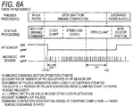
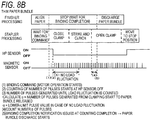
- Fig. 8 is a time chart illustrating a third operation example of the electric stapler according to the present embodiment.
- a thickness of the paper bundle P is detected based on a load, and a timing of discharging the paper bundle P is determined according to the thickness of the paper bundle P.
- Fig. 8A illustrates a case where the thickness of the paper bundle is large due to a large number of sheets of paper to be bound and the like
- Fig. 8B illustrates a case where the thickness of the paper bundle is small due to a small number of sheets of paper to be bound and the like.
- the post-processing device 502A illustrated in Fig. 4 outputs a binding command to the stapler 1A.
- the control unit 110 of the stapler 1A does not drive the motor 5 and does not execute the stapler processing.
- the control unit 110 rotates the motor 5 forward to rotate the driven gear 51 illustrated in Fig. 2 in one direction indicated by the arrow F.
- the control unit 110 When the home position sensor 101 detects the stop target range end-point position PE of the driven gear 51, that is, HP sensor OFF is detected at (2) in Figs. 8A and 8B , the control unit 110 starts counting the number of pulses and acquires rotation amount information D1 based on position information output from the magnetic sensor 102.
- the rotation amount information D1 is the number of pulses obtained by counting the number of pulses generated based on the position information accompanying the rotation of the motor 5.
- the (load fluctuation detection unit of) control unit 110 counts pulses generated accompanying the rotation of the motor 5 in a range of (3) in Figs. 8A and 8B since the detection of the HP sensor OFF at (2) in Figs. 8A and 8B , detects pulse width fluctuation in this range, and determines magnitude of a load based on the pulse width fluctuation.
- the control unit 110 may determine the magnitude of the load based on fluctuation in current flowing through the motor 5.
- a rotation amount (the number of pulses) of the motor 5 in a period from when the home position sensor 101 detects the stop target range end-point position PE of the driven gear 51 to when the paper bundle P can be discharged is determined according to the thickness of the paper bundle P to be bound, during which the clamping process, the penetrating process, and the clinching process are completed and the clamp part 2 is opened. Therefore, the number ⁇ of pulses generated from the start of clamping of the paper bundle P to release thereof is calculated.
- the pulse width indicating the load fluctuates in the range of (3) (there is a section where the pulse width is large).
- Fig. 8B when the thickness of the paper bundle P is small, there is no load fluctuation or the load fluctuation is small in the range of (3), and the fluctuation of the pulse width is within a predetermined range. When the fluctuation of the pulse width is within the predetermined range, it is determined that there is no load fluctuation.
- the control unit 110 estimates the thickness of the paper bundle P according to the load fluctuation, and according to the estimated thickness information of paper bundle P, sets discharge-possible rotation amount D4 (the number of pulses) of the motor 5 accumulated until the clamp part 2 is opened to allow discharging of the paper bundle P.
- the control unit 110 acquires the rotation amount information D1 (the number ⁇ of pulses) based on the position information output from the magnetic sensor 102, correspondingly to counting of the number of pulses in (4) of Figs. 8A and 8B .
- the control unit 110 outputs a binding completion notification to the post-processing device 502A correspondingly to counting completion at (5) in Figs. 8A and 8B .
- the post-processing device 502A When the binding completion notification from the stapler 1A is received, the post-processing device 502A performs the discharge processing of the paper bundle P. In a case where there is paper to be bound next when the discharge processing of the paper bundle P is completed, the paper alignment processing is performed to align the paper to be bound next.
- the control unit 110 When the home position sensor 101 detects the stop target range start-point position PS of the driven gear 51, the control unit 110 performs braking control of stopping the driving of the motor 5.
- the timing, at which the clamp part 2 is opened to allow discharging of the paper bundle P after the clinching process is completed, is determined based on the rotation amount information acquired based on the position information output from the magnetic sensor 102 and the paper bundle thickness information corresponding to the load, so that an optimum discharge timing of the paper bundle corresponding to the thickness of the paper bundle can be detected. For example, in a case where the load is small and the thickness of the paper bundle is small as illustrated in Fig. 8B , the clamp is released at an earlier timing than in a case where the load is large and the thickness of the paper bundle is large as illustrated in Fig. 8A .
- the binding completion notification from the stapler 1A to the post-processing device 502A at an earlier stage according to the thickness of the paper bundle P. Further, as described in the first operation example, even when the load changes, the optimum discharge timing of the paper bundle can be detected. Further, differently from the second operation example, it is not necessary to acquire the paper bundle thickness information from the image forming device 501A.
- 1A electric stapler 2 clamp part; 21 first wall portion; 22 second wall portion; 3 penetration part; 4 clinch part; 5 motor; 51 driven gear; 101 home position sensor; 102 magnetic sensor (rotation amount detection unit); 110 control unit (gripping release detection unit, paper bundle thickness information acquisition unit, paper sheet number acquisition unit, output unit, load fluctuation detection unit, thickness estimation unit); SE stop target range; PS stop target range start-point position; PE stop target range end-point position; P1 stop target position.
Landscapes
- Engineering & Computer Science (AREA)
- Mechanical Engineering (AREA)
- Life Sciences & Earth Sciences (AREA)
- Forests & Forestry (AREA)
- Textile Engineering (AREA)
- Folding Of Thin Sheet-Like Materials, Special Discharging Devices, And Others (AREA)
- Paper Feeding For Electrophotography (AREA)
- Dovetailed Work, And Nailing Machines And Stapling Machines For Wood (AREA)
Abstract
Description
- The present invention relates to an electric stapler that binds a paper bundle with a staple, a post-processing device on which the electric stapler is mounted, and an image forming system including the post-processing device.
- In an image forming system, which includes an image forming device using an electrophotographic technique and a post-processing device, the post-processing device may be equipped with an electric stapler that binds a paper bundle with a staple.
- The electric stapler includes a home position sensor that detects a rotational position of a gear driven by a motor, and is configured such that an output of the home position sensor becomes a predetermined output after a clamping process of clamping a paper bundle, a penetrating process of causing a staple to penetrate the paper bundle, and a clinching process of bending the staple are completed and clamping is released.
- In the electric stapler, the bound paper bundle being dischargeable is detected based on the output of the home position sensor, and is output to the post-processing device. In the post-processing device, when a notification that the bound paper bundle is being dischargeable is received from the electric stapler, discharge processing of the paper bundle is performed.
- On the other hand, there has been proposed a technique of determining detection of a home position sensor and determining a timing at which a paper bundle can be discharged with the passage of time (for example, see Patent Literature 1).
- Patent Literature 1:
JP-A-2011-201662 - In the electric stapler, when the clinching process ends and an operation of releasing the clamping starts, the paper bundle can be discharged. However, in a method of detecting, based on an output of a home position sensor, that a bound paper bundle can be discharged, discharge is not performed until an output signal from the home position sensor is received even though the paper bundle is actually in a dischargeable state, and therefore, unnecessary waiting is caused in a period from when the dischargeable state is established to when the output signal from the home position sensor is received.
- In addition, the time until completion of the clinching process varies depending on magnitude of a load (for example, whether the paper bundle is thin or thick). Accordingly, in a method of determining a timing at which the paper bundle can be discharged with the passage of time, when the timing at which the paper bundle can be discharged with the passage of time is determined on a basis of a case where the load is small (for example, a case where the paper bundle is thin), there is a possibility that the discharge of the paper bundle is started before the completion of the clinching process in a case where the load is large. In such a case, the post-processing device starts discharging the paper bundle although the stapler clamps the paper bundle, which is a main cause of a jam or a mechanical failure.
- It is therefore an exemplary object of the present invention to provide an electric stapler capable of detecting a suitable discharge timing, preferably an optimum discharge timing, of a paper bundle. In addition, it is an exemplary object to provide a post-processing device on which such an electric stapler is mounted, and an image forming system including the post-processing device.
- In order to solve the above-described problem, an electric stapler according to the present disclosure is an electric stapler, including: a clamp part that is configured to include a first wall portion and a second wall portion facing each other with a predetermined gap therebetween, in which the first wall portion is movable in directions of approaching and separating from the second wall portion, and that grips a paper bundle inserted between the first wall portion and the second wall portion by moving the first wall portion in the direction of approaching the second wall portion; a penetration part that causes a staple to penetrate the paper bundle gripped by the clamp part; a clinch part that bends the staple penetrating the paper bundle to bind the paper bundle; a gripping release detection unit that detects that the paper bundle is released from gripping after the first wall portion moves in the direction of separating from the second wall portion from a state where the paper bundle is gripped by the clamp part; and an output unit that, after it is detected that the paper bundle is released from gripping of the clamp part, outputs a gripping release signal indicating that the paper bundle is released from gripping of the clamp part to an outside.
- In the above-described electric stapler, when it is detected that the paper bundle is released from gripping of the clamp part, a gripping release signal is output to the outside, and processing based on the gripping release signal is performed.
- According to the electric stapler described above, since a gripping release signal is output when it is detected that a paper bundle is actually released from gripping of a clamp part, it is possible to detect a suitable discharge timing, preferably an optimum discharge timing, of the paper bundle.
-
-
Fig. 1 is a side view illustrating an example of an electric stapler according to an embodiment. -
Fig. 2 is a side sectional view illustrating an example of a driving unit. -
Fig. 3 is a block diagram illustrating an example of control functions of the electric stapler. -
Fig. 4 is a configuration diagram illustrating an overview of an image forming system according to the present embodiment. -
Fig. 5A is a time chart illustrating an operation example of an electric stapler in the related art. -
Fig. 5B is a time chart illustrating an operation example of the electric stapler in the related art. -
Fig. 6A is a time chart illustrating a first operation example of the electric stapler according to the present embodiment. -
Fig. 6B is a time chart illustrating the first operation example of the electric stapler according to the present embodiment. -
Fig. 7A is a time chart illustrating a second operation example of the electric stapler according to the present embodiment. -
Fig. 7B is a time chart illustrating the second operation example of the electric stapler according to the present embodiment. -
Fig. 8A is a time chart illustrating a third operation example of the electric stapler according to the present embodiment. -
Fig. 8B is a time chart illustrating the third operation example of the electric stapler according to the present embodiment. - Hereinafter, embodiments of an electric stapler, a post-processing device on which the electric stapler is mounted, and an image forming system including the post-processing device according to the present invention will be described with reference to the drawings.
-
Fig. 1 is a side sectional view illustrating an example of an electric stapler according to an embodiment. - An
electric stapler 1A includes aclamp part 2 that clamps a paper bundle P, apenetration part 3 that causes astaple 10 to penetrate the paper bundle P, and aclinch part 4 that bends thestaple 10 penetrating the paper bundle P to bind the paper bundle P. In addition, theelectric stapler 1A includes amotor 5 that drives theclamp part 2, thepenetration part 3, and theclinch part 4. - The
electric stapler 1A includes astriking unit 30 in which thepenetration part 3 is provided, and abinding unit 40 in which theclinch part 4 is provided. - The
clamp part 2 includes afirst wall portion 21 and asecond wall portion 22 that face each other with a predetermined gap therebetween. In theclamp part 2, thefirst wall portion 21 is formed at a portion facing thestriking unit 30 of thebinding unit 40. Further, in theclamp part 2, thesecond wall portion 22 is formed at a portion facing thebinding unit 40 of thestriking unit 30. - The
binding unit 40 moves in directions approaching and separating from thestriking unit 30 by a rotating operation with ashaft 31 serving as a fulcrum. - Accordingly, in the
clamp part 2, thefirst wall portion 21 moves in directions of approaching and separating from thesecond wall portion 22. Theclamp part 2 sandwiches the paper bundle P between thefirst wall portion 21 and thesecond wall portion 22 when thefirst wall portion 21 is moved in a direction of approaching thesecond wall portion 22. When thefirst wall portion 21 moves in a direction of separating from thesecond wall portion 22, the paper bundle P sandwiched between thefirst wall portion 21 and thesecond wall portion 22 is released. - A
cartridge 100, in which thestaples 10 are accommodated in a connected state, is detachably attached to thestriking unit 30. Thepenetration part 3 separates one leading staple of thestaples 10 accommodated in thecartridge 100, and strikes thestaple 10 toward the paper bundle P sandwiched between thefirst wall portion 21 and thesecond wall portion 22 to penetrate the paper bundle P. Thepenetration part 3 may include a movable part movable between a first position and a second position. The second position is apart from the first position in the direction orthogonal to a surface of the paper bundle. - The
striking unit 30 includes a mechanism that feeds thestaple 10 accommodated in thecartridge 100 to a position where thestaple 10 can be struck by thepenetration part 3. In addition, thestriking unit 30 includes a mechanism that forms thestaple 10 into a U shape, with the staples in a form of being connected in a sheet shape and accommodated in thecartridge 100 for supply. - The
clinch part 4 bends thestaple 10 penetrating the paper bundle P sandwiched between thefirst wall portion 21 and thesecond wall portion 22 in a predetermined direction. Thebinding unit 40 may include a mechanism that cuts legs of thestaple 10 penetrating the paper bundle P. Theclinch part 4 may include a contact surface which comes into contact with the staple 10 to bend thestaple 10. -
Fig. 2 is a side sectional view illustrating an example of a driving unit. Theelectric stapler 1A includes a drivingunit 50 that transmits rotation of themotor 5 to theclamp part 2, thepenetration part 3, and theclinch part 4. The drivingunit 50 includes a drivengear 51 that transmits the rotation of themotor 5 to theclamp part 2, thepenetration part 3, and theclinch part 4, and anintermediate gear 52 that transmits the rotation of themotor 5 to the drivengear 51. - In the driving
unit 50, rotation of amotor shaft 5a of themotor 5 is transmitted to the drivengear 51 via theintermediate gear 52, and the drivengear 51 rotates. When rotation of the drivengear 51 is transmitted to a cam or the like (not illustrated), the drivingunit 50 moves the bindingunit 40 in directions of approaching and separating from the strikingunit 30, and opens and closes theclamp part 2. In addition, the drivingunit 50 drives thepenetration part 3 and theclinch part 4 by transmitting the rotation of the drivengear 51 to a cam or the like (not illustrated). - In the
electric stapler 1A, in an operation of the drivengear 51 rotating in one direction, the bindingunit 40 moves in a direction of approaching the strikingunit 30, and the paper bundle P is clamped by theclamp part 2. - Further, in the
electric stapler 1A, in the operation of the drivengear 51 rotating in the one direction, thestaples 10 accommodated in thecartridge 100 are fed out, and one leadingstaple 10 of the fed-outstaples 10 is struck by thepenetration part 3 toward the paper bundle P clamped by theclamp part 2 to penetrate the paper bundle P. - Further, in the
electric stapler 1A, in the operation of the drivengear 51 rotating in the one direction, the staple 10 penetrating the paper bundle P is bent by theclinch part 4 by, and in the operation of the drivengear 51 further rotating in the one direction, the bindingunit 40 is moved in a direction of separating from the strikingunit 30, and the clamping of the paper bundle P by theclamp part 2 is released. - Further, in the operation of the driven
gear 51 rotating in the one direction, theelectric stapler 1A performs a clamping process of clamping the paper bundle P with theclamp part 2, a penetrating process of striking the staple 10 into the paper bundle P with thepenetration part 3, a clinching process of bending the staple 10 with theclinch part 4, and a returning process of releasing the paper bundle P clamped by theclamp part 2. - Next, a configuration for detecting positions and rotation amounts of the
motor 5 and the drivengear 51 in a rotation direction will be described. - In the
electric stapler 1A, a position along a rotation direction of themotor shaft 5a of themotor 5 is referred to as a rotational position of themotor 5. In addition, a position along a rotation direction of the drivengear 51 is referred to as a rotational position of the drivengear 51. - In the driving
unit 50, the drivengear 51 meshes with theintermediate gear 52 and theintermediate gear 52 meshes with a gear (not illustrated) of themotor shaft 5a, and thus a rotational speed of the drivengear 51 is a value obtained by reducing a rotational speed of themotor 5 at a predetermined reduction ratio. Accordingly, a rotational position and a rotation amount of the drivengear 51 are proportional to a rotational position and a rotation amount of themotor 5. - Therefore, a home position sensor 101 (first position detection unit) that detects a rotational position of the driven
gear 51 is provided for the rotational positions of themotor 5 and the drivengear 51. With respect to the rotation amounts of themotor 5 and the drivengear 51, the rotation amount of themotor 5 is detected based on an output of a magnetic sensor 102 (rotation amount detection unit) used for detecting a position of a rotor (not illustrated) of themotor 5 that is configured with a brushless motor. - In the
electric stapler 1A, thehome position sensor 101 detects the rotational position of the drivengear 51 in order to cause theclamp part 2, thepenetration part 3, and theclinch part 4 to standby at a predetermined home position. - In the
electric stapler 1A, a stop target range SE is set to a predetermined range in a circumferential direction of the drivengear 51 in order to stop the rotational position of the drivengear 51 at a predetermined position when stopping driving of themotor 5 or in order to detect a timing for discharging the paper bundle P. - The
electric stapler 1A is configured such that an output of thehome position sensor 101 changes from 0 (OFF) to 1 (ON), for example, when a stop target range start-point position PS, which is a start-point of the stop target range SE, reaches a detection position P101 of thehome position sensor 101 with respect to rotation of the drivengear 51 in a forward direction indicated by an arrow F. - Further, the
electric stapler 1A is configured such that the output of thehome position sensor 101 changes from 1 (ON) to 0 (OFF), for example, when a stop target range end-point position PE, which is an end-point of the stop target range SE, reaches the detection position P101 of thehome position sensor 101 with respect to the rotation of the drivengear 51 in the forward direction indicated by the arrow F. - Accordingly, the
electric stapler 1A is configured such that thehome position sensor 101 can detect the stop target range SE of the drivengear 51. - In the
electric stapler 1A, the stop target position P1 of the drivengear 51 is set within the stop target range SE. In theelectric stapler 1A, when the stop target position P1 of the drivengear 51 is located at the detection position P101 of thehome position sensor 101, theclamp part 2, thepenetration part 3, and theclinch part 4 are located at respective home positions. - In the
electric stapler 1A, when the drivengear 51 is rotated in the forward direction indicated by the arrow F by forward rotation of themotor 5 from a state where the stop target position P1 of the drivengear 51 is located at the detection position P101 of thehome position sensor 101, the stop target range end-point position PE reaches the detection position P101 of thehome position sensor 101. - With respect to the rotation of the driven
gear 51 in the forward direction indicated by the arrow F, a predetermined range from the stop target range end-point position PE is set as a clamp range CL in which clamping of the paper bundle P by theclamp part 2 is performed in the clamping process. Further, following the clamp range CL, a penetration range TH is set in which thestaple 10 is struck into the paper bundle P by thepenetration part 3 in the penetrating process. Following the penetration range TH, a clinch range of the clinching process is set, and following the clinch range, a clamp release range of the returning process is set, met by the stop target range start-point position PS. -
Fig. 3 is a block diagram illustrating an example of control functions of the stapler. Theelectric stapler 1A includes a control unit (controller) 110 that controls themotor 5 and a motor driving unit (a motor driving circuit) 111 that drives themotor 5. - The control unit 110 (implementing a gripping release detection unit, a paper bundle thickness information acquisition unit, a paper sheet number acquisition unit, an output unit, a load fluctuation detection unit, and a thickness estimation unit) includes a
CPU 110a, and executes the binding processing of theelectric stapler 1A by executing a program stored in astorage unit 110b. Themotor driving unit 111 drives themotor 5 by known PWM control based on position information of a rotor (not illustrated) output from themagnetic sensor 102. - The
control unit 110 detects the timing, at which the paper bundle P can be discharged, based on the rotational position of the drivengear 51 detected by thehome position sensor 101 and the rotation amount of themotor 5 detected by themagnetic sensor 102, that is, the rotation amount of the drivengear 51. -
Fig. 4 is a configuration diagram illustrating an overview of an image forming system according to the present embodiment. Animage forming system 500A of the present embodiment includes animage forming device 501A and apost-processing device 502A that is capable of performing at least one type of processing. Theimage forming device 501A forms and outputs an image on a sheet of paper fed from a paper feeding portion (not illustrated) inside or outside the device. In this example, theimage forming device 501A forms an image on a sheet of paper by forming an electrostatic latent image by scanning exposure, developing the electrostatic latent image with toner, transferring the toner to the sheet of paper, and fixing the toner. Thepost-processing device 502A includes the above-describedelectric stapler 1A in abinding part 503A. - In the
electric stapler 1A, theCPU 110a of thecontrol unit 110 illustrated inFig. 3 is connected to a control unit (not illustrated) of thepost-processing device 502A and a control unit (not illustrated) of theimage forming device 501A. Theimage forming device 501A instructs thepost-processing device 502A to perform the binding processing when performing the binding processing of binding the paper bundle P is selected by an operation part (not illustrated). Thepost-processing device 502A performs paper alignment processing of aligning a predetermined number of sheets of paper output from theimage forming device 501A, and outputs a binding command to thestapler 1A when the paper alignment processing is completed. In addition, when the paper bundle P is bound by thestapler 1A and a binding completion notification is received at a predetermined timing to be described later, thepost-processing device 502A performs discharge processing of the bound paper bundle P. When there is paper to be bound next, the paper alignment processing is performed to align the paper to be bound next. -
Fig. 5 is a time chart illustrating an operation example of an electric stapler in the related art. A specific example of the problem described in the section of "Technical Problem" will be described.Fig. 5A illustrates an example in which a timing at which the paper bundle P can be discharged is determined based on ON-OFF-ON detection of the home position sensor. Note thatFig. 1 and the like are used for the configuration of the electric stapler in the related art. - The
electric stapler 1A is configured such that after thehome position sensor 101 detects the stop target range end-point position PE of the drivengear 51 illustrated inFig. 2 (detection of HP sensor OFF), the clamping process, the penetrating process, and the clinching process are completed, and after theclamp part 2 is opened, thehome position sensor 101 detects the stop target range start-point position PS of the driven gear 51 (detection of HP sensor ON). - However, before a timing at which the
home position sensor 101 detects the stop target range start-point position PS of the driven gear 51 (detection of HP sensor ON), the clinching process is completed and an operation of the opening theclamp part 2 starts, and actually the paper bundle P can be discharged. Therefore, as indicated by (5) ofFig. 5A , unnecessary waiting occurs in a period from when actually the paper bundle P can be discharged to when the HP sensor ON is detected. -
Fig. 5B illustrates an example in which a timing at which the paper bundle P can be discharged is determined with the passage of time since detection of the home position sensor OFF. - In a case where a load is small, a force for causing the staple 10 to penetrate the paper bundle P is smaller than that in a case where the load is large. Accordingly, a rotational speed of the
motor 5 in stapler processing is increased. On the other hand, in the case where the load is large, the force for causing the staple 10 to penetrate the paper bundle P is larger than that in the case where the load is small. Accordingly, the rotational speed of themotor 5 in the stapler processing is reduced. - Therefore, time from when the
home position sensor 101 detects the stop target range end-point position PE of the driven gear 51 (detection of HP sensor OFF) to when the clinching process is completed varies depending on the magnitude of the load. Normally, the time from when thehome position sensor 101 detects the stop target range end-point position PE of the driven gear 51 (detection of HP sensor OFF) to when the clinching process is completed is shorter in the case where the load is small than in the case where the load is large. - Accordingly, as illustrated in
Fig. 5B , when the timing at which the paper bundle P can be discharged is determined with the passage of time since the detection of thehome position sensor 101 OFF on the basis of the case where the load is small, there is a possibility that the discharge of the paper bundle P is started before completion of the clinching process in the case where the load is large. In such a case, the post-processing device starts discharging the paper bundle although the stapler clamps the paper bundle, which is a main cause of a jam or a mechanical failure. -
Figs. 6A and6B are time charts illustrating a first operation example of the electric stapler according to the present embodiment, in whichFig. 6A illustrates a case where the load is small due to a small number of sheets of paper to be bound or the like, andFig. 6B illustrates a case where the load is large due to a large number of sheets of paper to be bound or the like. - When the paper alignment processing is completed, the
post-processing device 502A illustrated inFig. 4 outputs a binding command to thestapler 1A. Until the paper alignment processing is completed and a binding command is issued in finisher processing in thepost-processing device 502A, thecontrol unit 110 of thestapler 1A does not drive themotor 5 and does not execute the stapler processing. - When a binding command from the
post-processing device 502A is received correspondingly to a binding command at (1) inFigs. 6A and6B , thecontrol unit 110 rotates themotor 5 forward to rotate the drivengear 51 illustrated inFig. 2 in one direction indicated by the arrow F. - When the
home position sensor 101 detects the stop target range end-point position PE of the drivengear 51, that is, HP sensor OFF is detected at (2) inFigs. 6A and6B , thecontrol unit 110 starts counting the number of pulses from themagnetic sensor 102. At the start of counting the number of pulses, rotation amount information D1 is acquired based on position information output from themagnetic sensor 102. The rotation amount information D1 is the number of pulses obtained by counting the number of pulses generated based on the position information accompanying the rotation of themotor 5. - In this example, a rotation amount (the number of pulses) of the
motor 5 in a period from when thehome position sensor 101 detects the stop target range end-point position PE of the drivengear 51 to when the paper bundle P can be discharged is determined in advance. During the period, the clamping process, the penetrating process, and the clinching process are completed, and thereafter thefirst wall portion 21 starts to move in a direction of separating from thesecond wall portion 22 so that theclamp part 2 is opened. The rotation amount is, for example, a rotation amount of themotor 5 at the time when clamping of the paper bundle P with a maximum number of sheets that can be bound in theelectric stapler 1A can be released. The rotation amount of themotor 5 in the period from when the stop target range end-point position PE of the drivengear 51 is detected to when the paper bundle P can be discharged is referred to as a discharge-possible rotation amount D2, during which the clinching process is completed and theclamp part 2 is opened. However, the discharge-possible rotation amount D2 is set before the home position sensor is turned ON. - When the rotation amount information D1, which is acquired based on the position information output from the
magnetic sensor 102 after the stop target range end-point position PE of the drivengear 51 is detected, reaches the discharge-possible rotation amount D2, thecontrol unit 110 determines that the paper bundle P can be released from the clamping (gripping), and outputs a binding completion notification (gripping release signal) to thepost-processing device 502A correspondingly to counting completion at (3) inFigs. 6A and6B . Theelectric stapler 1A may include an interface for outputting the signal. In this example, the rotation amount of themotor 5, that is, the number of pulses at which the paper bundle P can be discharged is constant. But as indicated by (2)-(3) ofFig. 6A , in the case where the load is small, for example, when the paper bundle P is thin, themotor 5 rotates faster, and as indicated by (2)-(3) ofFig. 6B , in the case where the load is large, for example, when the paper bundle P is thick, themotor 5 rotates slower than when the load is small. - When the binding completion notification from the
stapler 1A is received, thepost-processing device 502A performs the discharge processing of the paper bundle P. In a case where there is paper to be bound next when the discharge processing of the paper bundle P is completed, the paper alignment processing is performed to align the paper to be bound next. - When the
home position sensor 101 detects the stop target range start-point position PS of the drivengear 51, that is, the HP sensor ON is detected at (4) inFigs. 6A and6B , thecontrol unit 110 performs braking control of stopping the driving of themotor 5. This braking control is also referred to as braking or applying a brake. - After the HP sensor ON is detected at (4) in
Figs. 6A and6B , thecontrol unit 110 stops the rotation of themotor 5 correspondingly to motor stop at (5) ofFigs. 6A and6B so as to locate the stop target position P1 of the drivengear 51 at the detection position P101 of thehome position sensor 101. Accordingly, theclamp part 2, thepenetration part 3, and theclinch part 4 stop at respective home positions. - As described above, the timing, at which the
clamp part 2 is opened to allow discharging of the paper bundle P can be discharged after the clinching process is completed, is determined based on the rotation amount information acquired based on the position information output from themagnetic sensor 102, so that an optimum discharge timing of the paper bundle can be detected even when the load is changed. Accordingly, by the ON-OFF-ON detection of the home position sensor, it is possible to reduce unnecessary waiting, which is a problem in the related art in which the timing at which the paper bundle P can be discharged is determined. In addition, it is possible to eliminate the possibility that the discharge of the paper bundle P is started before the completion of the clinching process, which is a problem in the related art in which the timing at which the paper bundle P can be discharged is determined with the passage of time since the detection of the home position sensor OFF. Factors of load fluctuation include a thickness of the paper bundle, a paper type, humidity of paper, temperature of the motor, voltage fluctuation, individual mechanical difference, mechanical aging degradation, and the like. -
Fig. 7 is a time chart illustrating a second operation example of the electric stapler according to the present embodiment. In the second operation example, information specifying a thickness of the paper bundle P is acquired from theimage forming device 501A or thepost-processing device 502A, and a timing of discharging the paper bundle P is determined according to the thickness of the paper bundle P.Fig. 7A illustrates a case where the thickness of the paper bundle is large due to a large number of sheets of paper to be bound and the like, andFig. 7B illustrates a case where the thickness of the paper bundle is small due to a small number of sheets of paper to be bound and the like. - When thickness information of the paper bundle P is acquired from the
image forming device 501A or thepost-processing device 502A, (the paper bundle thickness information acquisition unit of) thecontrol unit 110 calculates, based on the thickness information, the discharge-possible rotation amount D3 (which will be described later) at which the clamping of the paper bundle P is released. The thickness information of the paper bundle P includes information of a thickness of the paper bundle P, the number of sheets of paper to be bound, paper quality, basis weight, and the like. - The
post-processing device 502A outputs the thickness information of the paper bundle P to thestaple 1A, and outputs a binding command to thestapler 1A when paper alignment processing is completed. Until the paper alignment processing is completed and the binding command is issued in finisher processing in thepost-processing device 502A, thecontrol unit 110 of thestapler 1A does not drive themotor 5 and does not execute the stapler processing. - When the binding command from the
post-processing device 502A is received correspondingly to a binding command at (1) inFigs. 7A and7B , thecontrol unit 110 rotates themotor 5 forward to rotate the drivengear 51 illustrated inFig. 2 in one direction indicated by the arrow F. - When the
home position sensor 101 detects the stop target range end-point position PE of the drivengear 51, that is, HP sensor OFF is detected at (2) inFigs. 7A and7B , thecontrol unit 110 starts counting the number of pulses and acquires rotation amount information D1 based on position information output from themagnetic sensor 102. The rotation amount information D1 is the number of pulses obtained by counting the number of pulses generated based on the position information accompanying the rotation of themotor 5. - A rotation amount (the number of pulses) of the
motor 5 in a period from when thehome position sensor 101 detects the stop target range end-point position PE of the drivengear 51 to when the paper bundle P can be discharged is determined according to the thickness of the paper bundle P to be bound, during which the clamping process, the penetrating process, and the clinching process are completed and theclamp part 2 is opened. The rotation amount of themotor 5 corresponding to the thickness information of the paper bundle and in the period from when the stop target range end-point position PE of the drivengear 51 is detected to when the paper bundle P can be discharged is referred to as a discharge-possible rotation amount D3, during which the clinching process is completed and theclamp part 2 is opened. Thecontrol unit 110 sets the discharge-possible rotation amount D3 corresponding to the thickness information of the paper bundle. - When the rotation amount information D1, which is acquired based on the position information output from the
magnetic sensor 102 after the stop target range end-point position PE of the drivengear 51 is detected, reaches the discharge-possible rotation amount D3 corresponding to the thickness information of the paper bundle acquired from thepost-processing device 502A, (the gripping release detection unit of) thecontrol unit 110 determines that the paper bundle P can be released from the clamping (gripping), and outputs a binding completion notification to thepost-processing device 502A correspondingly to counting completion at (3) inFigs. 7A and7B . - When the binding completion notification from the
stapler 1A is received, thepost-processing device 502A performs the discharge processing of the paper bundle P. In a case where there is paper to be bound next when the discharge processing of the paper bundle P is completed, the paper alignment processing is performed to align the paper to be bound next. - When the
home position sensor 101 detects the stop target range start-point position PS of the drivengear 51, that is, the HP sensor ON is detected at (4) inFigs. 7A and7B , thecontrol unit 110 performs braking control of stopping the driving of themotor 5. - After the HP sensor ON is detected at (4) in
Figs. 7A and7B , thecontrol unit 110 stops the rotation of themotor 5 correspondingly to motor stop at (5) ofFigs. 7A and7B so as to locate the stop target position P1 of the drivengear 51 at the detection position P101 of thehome position sensor 101. Accordingly, theclamp part 2, thepenetration part 3, and theclinch part 4 stop at respective home positions. - The timing, at which the
clamp part 2 is opened to allow discharging of the paper bundle P after the clinching process is completed, is determined based on the rotation amount information acquired based on the position information output from themagnetic sensor 102 and the thickness information of the paper bundle acquired from theimage forming device 501A, so that an optimum discharge timing of the paper bundle P corresponding to the thickness of the paper bundle can be detected. For example, in a case where the thickness of the paper bundle P is small as illustrated inFig. 7B , the clamp is released at an earlier timing than in a case where the thickness of the paper bundle P is large as illustrated inFig. 7A . Accordingly, it is possible to output the binding completion notification from thestapler 1A to thepost-processing device 502A at an earlier stage according to the thickness of the paper bundle P. Further, as described in the first operation example, even when the load changes, the optimum discharge timing of the paper bundle P can be detected. - The thickness of the paper bundle P is also defined by the number of sheets of paper to be bound. Therefore, the
image forming device 501A illustrated inFig. 4 outputs paper sheet number information for specifying the number of sheets of paper to be bound to thepost-processing device 502A. Thepost-processing device 502A outputs paper sheet number information to thestapler 1A, and (the paper sheet number acquisition unit of) thecontrol unit 110 of thestapler 1A acquires the paper sheet number information. - When the discharge-possible rotation amount D3 corresponding to the paper sheet number information is set and the rotation amount information D1 reaches the discharge-possible rotation amount D3 corresponding to the paper sheet number information acquired from the
post-processing device 502A, (the gripping release detection unit of) thecontrol unit 110 determines that the paper bundle P is released from the clamping (gripping), and outputs the binding completion notification to thepost-processing device 502A correspondingly to counting completion at (3) inFigs. 7A and7B . -
Fig. 8 is a time chart illustrating a third operation example of the electric stapler according to the present embodiment. In the third operation example, a thickness of the paper bundle P is detected based on a load, and a timing of discharging the paper bundle P is determined according to the thickness of the paper bundle P.Fig. 8A illustrates a case where the thickness of the paper bundle is large due to a large number of sheets of paper to be bound and the like, andFig. 8B illustrates a case where the thickness of the paper bundle is small due to a small number of sheets of paper to be bound and the like. - When the paper alignment processing is completed, the
post-processing device 502A illustrated inFig. 4 outputs a binding command to thestapler 1A. Until the paper alignment processing is completed and the binding command is issued in finisher processing in thepost-processing device 502A, thecontrol unit 110 of thestapler 1A does not drive themotor 5 and does not execute the stapler processing. - When the binding command from the
post-processing device 502A is received correspondingly to a binding command at (1) inFigs. 8A and8B , thecontrol unit 110 rotates themotor 5 forward to rotate the drivengear 51 illustrated inFig. 2 in one direction indicated by the arrow F. - When the
home position sensor 101 detects the stop target range end-point position PE of the drivengear 51, that is, HP sensor OFF is detected at (2) inFigs. 8A and8B , thecontrol unit 110 starts counting the number of pulses and acquires rotation amount information D1 based on position information output from themagnetic sensor 102. The rotation amount information D1 is the number of pulses obtained by counting the number of pulses generated based on the position information accompanying the rotation of themotor 5. The (load fluctuation detection unit of)control unit 110 counts pulses generated accompanying the rotation of themotor 5 in a range of (3) inFigs. 8A and8B since the detection of the HP sensor OFF at (2) inFigs. 8A and8B , detects pulse width fluctuation in this range, and determines magnitude of a load based on the pulse width fluctuation. Thecontrol unit 110 may determine the magnitude of the load based on fluctuation in current flowing through themotor 5. - A rotation amount (the number of pulses) of the
motor 5 in a period from when thehome position sensor 101 detects the stop target range end-point position PE of the drivengear 51 to when the paper bundle P can be discharged is determined according to the thickness of the paper bundle P to be bound, during which the clamping process, the penetrating process, and the clinching process are completed and theclamp part 2 is opened. Therefore, the number α of pulses generated from the start of clamping of the paper bundle P to release thereof is calculated. - As illustrated in
Fig. 8A , when the paper bundle P is thick, the pulse width indicating the load fluctuates in the range of (3) (there is a section where the pulse width is large). On the other hand, as illustrated inFig. 8B , when the thickness of the paper bundle P is small, there is no load fluctuation or the load fluctuation is small in the range of (3), and the fluctuation of the pulse width is within a predetermined range. When the fluctuation of the pulse width is within the predetermined range, it is determined that there is no load fluctuation. As described above, (the thickness estimation unit of) thecontrol unit 110 estimates the thickness of the paper bundle P according to the load fluctuation, and according to the estimated thickness information of paper bundle P, sets discharge-possible rotation amount D4 (the number of pulses) of themotor 5 accumulated until theclamp part 2 is opened to allow discharging of the paper bundle P. - After the stop target range end-point position PE of the driven
gear 51 is detected, thecontrol unit 110 acquires the rotation amount information D1 (the number α of pulses) based on the position information output from themagnetic sensor 102, correspondingly to counting of the number of pulses in (4) ofFigs. 8A and8B . When the rotation amount information D1 reaches the discharge-possible rotation amount D4 corresponding to the load based on the position information output from themagnetic sensor 102, thecontrol unit 110 outputs a binding completion notification to thepost-processing device 502A correspondingly to counting completion at (5) inFigs. 8A and8B . - When the binding completion notification from the
stapler 1A is received, thepost-processing device 502A performs the discharge processing of the paper bundle P. In a case where there is paper to be bound next when the discharge processing of the paper bundle P is completed, the paper alignment processing is performed to align the paper to be bound next. - When the
home position sensor 101 detects the stop target range start-point position PS of the drivengear 51, thecontrol unit 110 performs braking control of stopping the driving of themotor 5. - The timing, at which the
clamp part 2 is opened to allow discharging of the paper bundle P after the clinching process is completed, is determined based on the rotation amount information acquired based on the position information output from themagnetic sensor 102 and the paper bundle thickness information corresponding to the load, so that an optimum discharge timing of the paper bundle corresponding to the thickness of the paper bundle can be detected. For example, in a case where the load is small and the thickness of the paper bundle is small as illustrated inFig. 8B , the clamp is released at an earlier timing than in a case where the load is large and the thickness of the paper bundle is large as illustrated inFig. 8A . Accordingly, it is possible to output the binding completion notification from thestapler 1A to thepost-processing device 502A at an earlier stage according to the thickness of the paper bundle P. Further, as described in the first operation example, even when the load changes, the optimum discharge timing of the paper bundle can be detected. Further, differently from the second operation example, it is not necessary to acquire the paper bundle thickness information from theimage forming device 501A. - 1A electric stapler; 2 clamp part; 21 first wall portion; 22 second wall portion; 3 penetration part; 4 clinch part; 5 motor; 51 driven gear; 101 home position sensor; 102 magnetic sensor (rotation amount detection unit); 110 control unit (gripping release detection unit, paper bundle thickness information acquisition unit, paper sheet number acquisition unit, output unit, load fluctuation detection unit, thickness estimation unit); SE stop target range; PS stop target range start-point position; PE stop target range end-point position; P1 stop target position.
Claims (13)
- An electric stapler, comprising:a clamp part that is configured to include a first wall portion and a second wall portion facing each other with a predetermined gap therebetween, in which the first wall portion is movable in directions of approaching and separating from the second wall portion, and that grips a paper bundle inserted between the first wall portion and the second wall portion by moving the first wall portion in the direction of approaching the second wall portion;a penetration part that causes a staple to penetrate the paper bundle gripped by the clamp part;a clinch part that bends the staple penetrating the paper bundle to bind the paper bundle;a gripping release detection unit that detects that the paper bundle is released from gripping after the first wall portion moves in the direction of separating from the second wall portion from a state where the paper bundle is gripped by the clamp part; andan output unit that, after it is detected that the paper bundle is released from gripping of the clamp part, outputs a gripping release signal indicating that the paper bundle is released from gripping of the clamp part to an outside.
- The electric stapler according to claim 1, further comprising:a motor that moves the first wall portion,wherein the first wall portion moves in accordance with a rotation amount of the motor, andwherein the gripping release detection unit detects, based on a rotation amount of the motor, that the paper bundle is released from gripping.
- The electric stapler according to claim 1 or 2, further comprising:a paper bundle thickness information acquisition unit that acquires paper bundle thickness information of the paper bundle inserted into the clamp part,wherein the gripping release detection unit detects, based on the paper bundle thickness information, that the paper bundle is released from gripping of the clamp part.
- The electric stapler according to any one of claims 1 to 3, further comprising:a paper sheet number acquisition unit that acquires paper sheet number information of the paper bundle inserted into the clamp part,wherein the gripping release detection unit detects, based on the paper sheet number information, that the paper bundle is released from gripping of the clamp part.
- The electric stapler according to claim 2, further comprising:a load fluctuation detection unit that detects load fluctuation of the motor at a time when the clamp part grips the paper bundle with the first wall portion and the second wall portion; anda thickness estimation unit that estimates a thickness of the paper bundle based on the load fluctuation,wherein the gripping release detection unit detects, based on the estimated thickness of the paper bundle, that the paper bundle is released from gripping of the clamp part.
- The electric stapler according to claim 5,
wherein the load fluctuation is detected based on a current value of the motor. - The electric stapler according to claim 5,
wherein the load fluctuation is detected based on a pulse width of a pulse generated accompanying rotation of the motor. - The electric stapler according to claim 3 or 4, wherein a rotation amount of the motor, at which the paper bundle is released from gripping of the clamp part, is set based on the paper bundle thickness information.
- The electric stapler according to claim 5, wherein the gripping release detection unit detects that the paper bundle is released from gripping of the clamp part when a rotation amount of the motor reaches the rotation amount at which the paper bundle is released from gripping of the clamp part.
- The electric stapler according to any one of claims 5 to 7, wherein a rotation amount of the motor, at which the paper bundle is released from gripping of the clamp part, is set according to the thickness of paper bundle estimated by the thickness estimation unit.
- The electric stapler according to claim 10, wherein the gripping release detection unit detects that the paper bundle is released from gripping of the clamp part when a rotation amount of the motor reaches the rotation amount at which the paper bundle is released from gripping of the clamp part.
- A post-processing device that comprises the electric stapler according to any one of claims 1 to 11, and performs processing based on the gripping release signal.
- An image forming system, comprising:a post-processing device that includes the electric stapler according to any one of claims 1 to 11, and performs processing based on the gripping release signal; andan image forming device.
Applications Claiming Priority (1)
| Application Number | Priority Date | Filing Date | Title |
|---|---|---|---|
| JP2020080671A JP7463829B2 (en) | 2020-04-30 | 2020-04-30 | Electric stapler, post-processing device and image forming system |
Publications (2)
| Publication Number | Publication Date |
|---|---|
| EP3904026A1 true EP3904026A1 (en) | 2021-11-03 |
| EP3904026B1 EP3904026B1 (en) | 2024-06-19 |
Family
ID=75728574
Family Applications (1)
| Application Number | Title | Priority Date | Filing Date |
|---|---|---|---|
| EP21170709.6A Active EP3904026B1 (en) | 2020-04-30 | 2021-04-27 | Electric stapler, post-processing device, and image forming system |
Country Status (3)
| Country | Link |
|---|---|
| US (1) | US11325805B2 (en) |
| EP (1) | EP3904026B1 (en) |
| JP (1) | JP7463829B2 (en) |
Families Citing this family (3)
| Publication number | Priority date | Publication date | Assignee | Title |
|---|---|---|---|---|
| US10363766B2 (en) * | 2013-03-15 | 2019-07-30 | G&K-Vijuk Intern. Corp. | Information item forming machine with visual inspection unit and method for forming and sorting informational items |
| JP7615857B2 (en) * | 2021-04-15 | 2025-01-17 | マックス株式会社 | Electric stapler and paper handling device |
| JP7632081B2 (en) * | 2021-05-28 | 2025-02-19 | 株式会社リコー | Post-processing device and image forming system |
Citations (3)
| Publication number | Priority date | Publication date | Assignee | Title |
|---|---|---|---|---|
| EP0779134B1 (en) * | 1995-12-11 | 2000-04-12 | Max Co., Ltd. | Electric stapler |
| JP2011201662A (en) | 2010-03-25 | 2011-10-13 | Fuji Xerox Co Ltd | Post-processing device and image forming device |
| EP2251147B1 (en) * | 2009-05-15 | 2016-08-10 | Max Co., Ltd. | Electric stapler and operation method of an electric stapler |
Family Cites Families (9)
| Publication number | Priority date | Publication date | Assignee | Title |
|---|---|---|---|---|
| US4181248A (en) * | 1978-05-15 | 1980-01-01 | Xerox Corporation | Fixed stapler head |
| JP4582599B2 (en) | 2000-02-08 | 2010-11-17 | キヤノンファインテック株式会社 | Stapler |
| US7407156B2 (en) * | 2005-03-22 | 2008-08-05 | Toshiba Tec Kabushiki Kaisha | Sheet finishing apparatus |
| JP2007261700A (en) | 2006-03-27 | 2007-10-11 | Canon Finetech Inc | Sheet treatment device and image forming device |
| JP2008127119A (en) | 2006-11-16 | 2008-06-05 | Canon Finetech Inc | Sheet processing device and image forming device |
| JP4885293B2 (en) * | 2009-09-11 | 2012-02-29 | キヤノンファインテック株式会社 | Sheet processing apparatus and image forming apparatus |
| JP4850300B2 (en) * | 2009-09-11 | 2012-01-11 | キヤノンファインテック株式会社 | Sheet processing apparatus and image forming apparatus |
| JP5668886B1 (en) | 2014-07-09 | 2015-02-12 | 富士ゼロックス株式会社 | Binding processing apparatus and image forming apparatus |
| JP2020079156A (en) * | 2018-11-14 | 2020-05-28 | コニカミノルタ株式会社 | Binding process device, image formation device, sheet bundle binding method and program |
-
2020
- 2020-04-30 JP JP2020080671A patent/JP7463829B2/en active Active
-
2021
- 2021-04-27 EP EP21170709.6A patent/EP3904026B1/en active Active
- 2021-04-30 US US17/245,046 patent/US11325805B2/en active Active
Patent Citations (3)
| Publication number | Priority date | Publication date | Assignee | Title |
|---|---|---|---|---|
| EP0779134B1 (en) * | 1995-12-11 | 2000-04-12 | Max Co., Ltd. | Electric stapler |
| EP2251147B1 (en) * | 2009-05-15 | 2016-08-10 | Max Co., Ltd. | Electric stapler and operation method of an electric stapler |
| JP2011201662A (en) | 2010-03-25 | 2011-10-13 | Fuji Xerox Co Ltd | Post-processing device and image forming device |
Also Published As
| Publication number | Publication date |
|---|---|
| JP2021172069A (en) | 2021-11-01 |
| EP3904026B1 (en) | 2024-06-19 |
| US20210339975A1 (en) | 2021-11-04 |
| US11325805B2 (en) | 2022-05-10 |
| JP7463829B2 (en) | 2024-04-09 |
Similar Documents
| Publication | Publication Date | Title |
|---|---|---|
| EP3904026B1 (en) | Electric stapler, post-processing device, and image forming system | |
| US7828276B2 (en) | Sheet processing apparatus and sheet processing method | |
| US8342067B2 (en) | Punching apparatus | |
| US11745382B2 (en) | Electric stapler, post-processing device, and image forming system | |
| US7134659B2 (en) | Delivery processing apparatus and image forming apparatus | |
| US9162838B2 (en) | Sheet conveying apparatus and image forming system | |
| US20040230336A1 (en) | Sheet processing apparatus and sheet processing method | |
| US7055815B2 (en) | Sheet processing apparatus with bundle delivery feature | |
| JP3621565B2 (en) | Sheet alignment apparatus and image forming apparatus | |
| US9501021B2 (en) | Sheet processing apparatus and image forming apparatus having binding processing function | |
| US7059506B2 (en) | Stapler apparatus | |
| US7922168B2 (en) | Method and device for transporting a sheet | |
| US8047525B2 (en) | Finisher, sheet discharging method and image forming apparatus | |
| JP4340531B2 (en) | Paper processing apparatus and image forming system | |
| US20210339423A1 (en) | Stapler, image forming device, and post-processing device | |
| JPH0597113A (en) | Band tying machine for recording device | |
| JP4554244B2 (en) | Paper processing apparatus and image forming apparatus | |
| EP3333103A1 (en) | Post-processing apparatus and control method | |
| JP2014157194A (en) | Sheet binding device and image forming apparatus | |
| JP2003238012A (en) | Sheet processing apparatus and image forming apparatus having the same | |
| JP2001031281A (en) | Sheet processing apparatus, image forming apparatus, sheet conveyance control method, and storage medium | |
| JP2015063363A (en) | Sheet processing device and image formation device | |
| JP2013129013A (en) | Sheet perforating apparatus, image forming system and sheet perforating method |
Legal Events
| Date | Code | Title | Description |
|---|---|---|---|
| PUAI | Public reference made under article 153(3) epc to a published international application that has entered the european phase |
Free format text: ORIGINAL CODE: 0009012 |
|
| STAA | Information on the status of an ep patent application or granted ep patent |
Free format text: STATUS: THE APPLICATION HAS BEEN PUBLISHED |
|
| AK | Designated contracting states |
Kind code of ref document: A1 Designated state(s): AL AT BE BG CH CY CZ DE DK EE ES FI FR GB GR HR HU IE IS IT LI LT LU LV MC MK MT NL NO PL PT RO RS SE SI SK SM TR |
|
| B565 | Issuance of search results under rule 164(2) epc |
Effective date: 20211001 |
|
| STAA | Information on the status of an ep patent application or granted ep patent |
Free format text: STATUS: REQUEST FOR EXAMINATION WAS MADE |
|
| 17P | Request for examination filed |
Effective date: 20220502 |
|
| RBV | Designated contracting states (corrected) |
Designated state(s): AL AT BE BG CH CY CZ DE DK EE ES FI FR GB GR HR HU IE IS IT LI LT LU LV MC MK MT NL NO PL PT RO RS SE SI SK SM TR |
|
| GRAP | Despatch of communication of intention to grant a patent |
Free format text: ORIGINAL CODE: EPIDOSNIGR1 |
|
| STAA | Information on the status of an ep patent application or granted ep patent |
Free format text: STATUS: GRANT OF PATENT IS INTENDED |
|
| INTG | Intention to grant announced |
Effective date: 20240112 |
|
| GRAS | Grant fee paid |
Free format text: ORIGINAL CODE: EPIDOSNIGR3 |
|
| GRAA | (expected) grant |
Free format text: ORIGINAL CODE: 0009210 |
|
| STAA | Information on the status of an ep patent application or granted ep patent |
Free format text: STATUS: THE PATENT HAS BEEN GRANTED |
|
| AK | Designated contracting states |
Kind code of ref document: B1 Designated state(s): AL AT BE BG CH CY CZ DE DK EE ES FI FR GB GR HR HU IE IS IT LI LT LU LV MC MK MT NL NO PL PT RO RS SE SI SK SM TR |
|
| REG | Reference to a national code |
Ref country code: GB Ref legal event code: FG4D |
|
| REG | Reference to a national code |
Ref country code: CH Ref legal event code: EP |
|
| REG | Reference to a national code |
Ref country code: DE Ref legal event code: R096 Ref document number: 602021014510 Country of ref document: DE |
|
| PG25 | Lapsed in a contracting state [announced via postgrant information from national office to epo] |
Ref country code: BG Free format text: LAPSE BECAUSE OF FAILURE TO SUBMIT A TRANSLATION OF THE DESCRIPTION OR TO PAY THE FEE WITHIN THE PRESCRIBED TIME-LIMIT Effective date: 20240619 |
|
| PG25 | Lapsed in a contracting state [announced via postgrant information from national office to epo] |
Ref country code: FI Free format text: LAPSE BECAUSE OF FAILURE TO SUBMIT A TRANSLATION OF THE DESCRIPTION OR TO PAY THE FEE WITHIN THE PRESCRIBED TIME-LIMIT Effective date: 20240619 Ref country code: HR Free format text: LAPSE BECAUSE OF FAILURE TO SUBMIT A TRANSLATION OF THE DESCRIPTION OR TO PAY THE FEE WITHIN THE PRESCRIBED TIME-LIMIT Effective date: 20240619 |
|
| REG | Reference to a national code |
Ref country code: LT Ref legal event code: MG9D |
|
| PG25 | Lapsed in a contracting state [announced via postgrant information from national office to epo] |
Ref country code: GR Free format text: LAPSE BECAUSE OF FAILURE TO SUBMIT A TRANSLATION OF THE DESCRIPTION OR TO PAY THE FEE WITHIN THE PRESCRIBED TIME-LIMIT Effective date: 20240920 |
|
| REG | Reference to a national code |
Ref country code: NL Ref legal event code: MP Effective date: 20240619 |
|
| PG25 | Lapsed in a contracting state [announced via postgrant information from national office to epo] |
Ref country code: LV Free format text: LAPSE BECAUSE OF FAILURE TO SUBMIT A TRANSLATION OF THE DESCRIPTION OR TO PAY THE FEE WITHIN THE PRESCRIBED TIME-LIMIT Effective date: 20240619 |
|
| PG25 | Lapsed in a contracting state [announced via postgrant information from national office to epo] |
Ref country code: NO Free format text: LAPSE BECAUSE OF FAILURE TO SUBMIT A TRANSLATION OF THE DESCRIPTION OR TO PAY THE FEE WITHIN THE PRESCRIBED TIME-LIMIT Effective date: 20240919 Ref country code: LV Free format text: LAPSE BECAUSE OF FAILURE TO SUBMIT A TRANSLATION OF THE DESCRIPTION OR TO PAY THE FEE WITHIN THE PRESCRIBED TIME-LIMIT Effective date: 20240619 Ref country code: HR Free format text: LAPSE BECAUSE OF FAILURE TO SUBMIT A TRANSLATION OF THE DESCRIPTION OR TO PAY THE FEE WITHIN THE PRESCRIBED TIME-LIMIT Effective date: 20240619 Ref country code: GR Free format text: LAPSE BECAUSE OF FAILURE TO SUBMIT A TRANSLATION OF THE DESCRIPTION OR TO PAY THE FEE WITHIN THE PRESCRIBED TIME-LIMIT Effective date: 20240920 Ref country code: FI Free format text: LAPSE BECAUSE OF FAILURE TO SUBMIT A TRANSLATION OF THE DESCRIPTION OR TO PAY THE FEE WITHIN THE PRESCRIBED TIME-LIMIT Effective date: 20240619 Ref country code: BG Free format text: LAPSE BECAUSE OF FAILURE TO SUBMIT A TRANSLATION OF THE DESCRIPTION OR TO PAY THE FEE WITHIN THE PRESCRIBED TIME-LIMIT Effective date: 20240619 Ref country code: RS Free format text: LAPSE BECAUSE OF FAILURE TO SUBMIT A TRANSLATION OF THE DESCRIPTION OR TO PAY THE FEE WITHIN THE PRESCRIBED TIME-LIMIT Effective date: 20240919 |
|
| PG25 | Lapsed in a contracting state [announced via postgrant information from national office to epo] |
Ref country code: NL Free format text: LAPSE BECAUSE OF FAILURE TO SUBMIT A TRANSLATION OF THE DESCRIPTION OR TO PAY THE FEE WITHIN THE PRESCRIBED TIME-LIMIT Effective date: 20240619 |
|
| REG | Reference to a national code |
Ref country code: AT Ref legal event code: MK05 Ref document number: 1695661 Country of ref document: AT Kind code of ref document: T Effective date: 20240619 |
|
| PG25 | Lapsed in a contracting state [announced via postgrant information from national office to epo] |
Ref country code: NL Free format text: LAPSE BECAUSE OF FAILURE TO SUBMIT A TRANSLATION OF THE DESCRIPTION OR TO PAY THE FEE WITHIN THE PRESCRIBED TIME-LIMIT Effective date: 20240619 |
|
| PG25 | Lapsed in a contracting state [announced via postgrant information from national office to epo] |
Ref country code: PT Free format text: LAPSE BECAUSE OF FAILURE TO SUBMIT A TRANSLATION OF THE DESCRIPTION OR TO PAY THE FEE WITHIN THE PRESCRIBED TIME-LIMIT Effective date: 20241021 |
|
| PG25 | Lapsed in a contracting state [announced via postgrant information from national office to epo] |
Ref country code: PT Free format text: LAPSE BECAUSE OF FAILURE TO SUBMIT A TRANSLATION OF THE DESCRIPTION OR TO PAY THE FEE WITHIN THE PRESCRIBED TIME-LIMIT Effective date: 20241021 |
|
| PG25 | Lapsed in a contracting state [announced via postgrant information from national office to epo] |
Ref country code: PL Free format text: LAPSE BECAUSE OF FAILURE TO SUBMIT A TRANSLATION OF THE DESCRIPTION OR TO PAY THE FEE WITHIN THE PRESCRIBED TIME-LIMIT Effective date: 20240619 |
|
| PG25 | Lapsed in a contracting state [announced via postgrant information from national office to epo] |
Ref country code: EE Free format text: LAPSE BECAUSE OF FAILURE TO SUBMIT A TRANSLATION OF THE DESCRIPTION OR TO PAY THE FEE WITHIN THE PRESCRIBED TIME-LIMIT Effective date: 20240619 |
|
| PG25 | Lapsed in a contracting state [announced via postgrant information from national office to epo] |
Ref country code: AT Free format text: LAPSE BECAUSE OF FAILURE TO SUBMIT A TRANSLATION OF THE DESCRIPTION OR TO PAY THE FEE WITHIN THE PRESCRIBED TIME-LIMIT Effective date: 20240619 Ref country code: IS Free format text: LAPSE BECAUSE OF FAILURE TO SUBMIT A TRANSLATION OF THE DESCRIPTION OR TO PAY THE FEE WITHIN THE PRESCRIBED TIME-LIMIT Effective date: 20241019 |
|
| PG25 | Lapsed in a contracting state [announced via postgrant information from national office to epo] |
Ref country code: CZ Free format text: LAPSE BECAUSE OF FAILURE TO SUBMIT A TRANSLATION OF THE DESCRIPTION OR TO PAY THE FEE WITHIN THE PRESCRIBED TIME-LIMIT Effective date: 20240619 |
|
| PG25 | Lapsed in a contracting state [announced via postgrant information from national office to epo] |
Ref country code: RO Free format text: LAPSE BECAUSE OF FAILURE TO SUBMIT A TRANSLATION OF THE DESCRIPTION OR TO PAY THE FEE WITHIN THE PRESCRIBED TIME-LIMIT Effective date: 20240619 Ref country code: SK Free format text: LAPSE BECAUSE OF FAILURE TO SUBMIT A TRANSLATION OF THE DESCRIPTION OR TO PAY THE FEE WITHIN THE PRESCRIBED TIME-LIMIT Effective date: 20240619 |
|
| PG25 | Lapsed in a contracting state [announced via postgrant information from national office to epo] |
Ref country code: ES Free format text: LAPSE BECAUSE OF FAILURE TO SUBMIT A TRANSLATION OF THE DESCRIPTION OR TO PAY THE FEE WITHIN THE PRESCRIBED TIME-LIMIT Effective date: 20240619 Ref country code: SM Free format text: LAPSE BECAUSE OF FAILURE TO SUBMIT A TRANSLATION OF THE DESCRIPTION OR TO PAY THE FEE WITHIN THE PRESCRIBED TIME-LIMIT Effective date: 20240619 |
|
| PG25 | Lapsed in a contracting state [announced via postgrant information from national office to epo] |
Ref country code: SM Free format text: LAPSE BECAUSE OF FAILURE TO SUBMIT A TRANSLATION OF THE DESCRIPTION OR TO PAY THE FEE WITHIN THE PRESCRIBED TIME-LIMIT Effective date: 20240619 Ref country code: SK Free format text: LAPSE BECAUSE OF FAILURE TO SUBMIT A TRANSLATION OF THE DESCRIPTION OR TO PAY THE FEE WITHIN THE PRESCRIBED TIME-LIMIT Effective date: 20240619 Ref country code: RO Free format text: LAPSE BECAUSE OF FAILURE TO SUBMIT A TRANSLATION OF THE DESCRIPTION OR TO PAY THE FEE WITHIN THE PRESCRIBED TIME-LIMIT Effective date: 20240619 Ref country code: PL Free format text: LAPSE BECAUSE OF FAILURE TO SUBMIT A TRANSLATION OF THE DESCRIPTION OR TO PAY THE FEE WITHIN THE PRESCRIBED TIME-LIMIT Effective date: 20240619 Ref country code: IS Free format text: LAPSE BECAUSE OF FAILURE TO SUBMIT A TRANSLATION OF THE DESCRIPTION OR TO PAY THE FEE WITHIN THE PRESCRIBED TIME-LIMIT Effective date: 20241019 Ref country code: ES Free format text: LAPSE BECAUSE OF FAILURE TO SUBMIT A TRANSLATION OF THE DESCRIPTION OR TO PAY THE FEE WITHIN THE PRESCRIBED TIME-LIMIT Effective date: 20240619 Ref country code: EE Free format text: LAPSE BECAUSE OF FAILURE TO SUBMIT A TRANSLATION OF THE DESCRIPTION OR TO PAY THE FEE WITHIN THE PRESCRIBED TIME-LIMIT Effective date: 20240619 Ref country code: CZ Free format text: LAPSE BECAUSE OF FAILURE TO SUBMIT A TRANSLATION OF THE DESCRIPTION OR TO PAY THE FEE WITHIN THE PRESCRIBED TIME-LIMIT Effective date: 20240619 Ref country code: AT Free format text: LAPSE BECAUSE OF FAILURE TO SUBMIT A TRANSLATION OF THE DESCRIPTION OR TO PAY THE FEE WITHIN THE PRESCRIBED TIME-LIMIT Effective date: 20240619 |
|
| PG25 | Lapsed in a contracting state [announced via postgrant information from national office to epo] |
Ref country code: IT Free format text: LAPSE BECAUSE OF FAILURE TO SUBMIT A TRANSLATION OF THE DESCRIPTION OR TO PAY THE FEE WITHIN THE PRESCRIBED TIME-LIMIT Effective date: 20240619 |
|
| REG | Reference to a national code |
Ref country code: DE Ref legal event code: R097 Ref document number: 602021014510 Country of ref document: DE |
|
| PG25 | Lapsed in a contracting state [announced via postgrant information from national office to epo] |
Ref country code: DK Free format text: LAPSE BECAUSE OF FAILURE TO SUBMIT A TRANSLATION OF THE DESCRIPTION OR TO PAY THE FEE WITHIN THE PRESCRIBED TIME-LIMIT Effective date: 20240619 |
|
| PLBE | No opposition filed within time limit |
Free format text: ORIGINAL CODE: 0009261 |
|
| STAA | Information on the status of an ep patent application or granted ep patent |
Free format text: STATUS: NO OPPOSITION FILED WITHIN TIME LIMIT |
|
| 26N | No opposition filed |
Effective date: 20250320 |
|
| PG25 | Lapsed in a contracting state [announced via postgrant information from national office to epo] |
Ref country code: SE Free format text: LAPSE BECAUSE OF FAILURE TO SUBMIT A TRANSLATION OF THE DESCRIPTION OR TO PAY THE FEE WITHIN THE PRESCRIBED TIME-LIMIT Effective date: 20240619 |
|
| REG | Reference to a national code |
Ref country code: CH Ref legal event code: H13 Free format text: ST27 STATUS EVENT CODE: U-0-0-H10-H13 (AS PROVIDED BY THE NATIONAL OFFICE) Effective date: 20251125 |
|
| PG25 | Lapsed in a contracting state [announced via postgrant information from national office to epo] |
Ref country code: LU Free format text: LAPSE BECAUSE OF NON-PAYMENT OF DUE FEES Effective date: 20250427 |
|
| PG25 | Lapsed in a contracting state [announced via postgrant information from national office to epo] |
Ref country code: MC Free format text: LAPSE BECAUSE OF FAILURE TO SUBMIT A TRANSLATION OF THE DESCRIPTION OR TO PAY THE FEE WITHIN THE PRESCRIBED TIME-LIMIT Effective date: 20240619 |
|
| GBPC | Gb: european patent ceased through non-payment of renewal fee |
Effective date: 20250427 |
|
| REG | Reference to a national code |
Ref country code: BE Ref legal event code: MM Effective date: 20250430 |
|
| PG25 | Lapsed in a contracting state [announced via postgrant information from national office to epo] |
Ref country code: GB Free format text: LAPSE BECAUSE OF NON-PAYMENT OF DUE FEES Effective date: 20250427 |
|
| PG25 | Lapsed in a contracting state [announced via postgrant information from national office to epo] |
Ref country code: FR Free format text: LAPSE BECAUSE OF NON-PAYMENT OF DUE FEES Effective date: 20250430 |
|
| PG25 | Lapsed in a contracting state [announced via postgrant information from national office to epo] |
Ref country code: BE Free format text: LAPSE BECAUSE OF NON-PAYMENT OF DUE FEES Effective date: 20250430 |
|
| PG25 | Lapsed in a contracting state [announced via postgrant information from national office to epo] |
Ref country code: CH Free format text: LAPSE BECAUSE OF NON-PAYMENT OF DUE FEES Effective date: 20250430 |
|
| PG25 | Lapsed in a contracting state [announced via postgrant information from national office to epo] |
Ref country code: IE Free format text: LAPSE BECAUSE OF NON-PAYMENT OF DUE FEES Effective date: 20250427 |
|
| PG25 | Lapsed in a contracting state [announced via postgrant information from national office to epo] |
Ref country code: CY Free format text: LAPSE BECAUSE OF FAILURE TO SUBMIT A TRANSLATION OF THE DESCRIPTION OR TO PAY THE FEE WITHIN THE PRESCRIBED TIME-LIMIT Effective date: 20240619 |
|
| PG25 | Lapsed in a contracting state [announced via postgrant information from national office to epo] |
Ref country code: LT Free format text: LAPSE BECAUSE OF FAILURE TO SUBMIT A TRANSLATION OF THE DESCRIPTION OR TO PAY THE FEE WITHIN THE PRESCRIBED TIME-LIMIT Effective date: 20240619 |
|
| PGFP | Annual fee paid to national office [announced via postgrant information from national office to epo] |
Ref country code: DE Payment date: 20260305 Year of fee payment: 6 |