EP3903976A1 - Rotating tool with coolant hole - Google Patents
Rotating tool with coolant hole Download PDFInfo
- Publication number
- EP3903976A1 EP3903976A1 EP19905782.9A EP19905782A EP3903976A1 EP 3903976 A1 EP3903976 A1 EP 3903976A1 EP 19905782 A EP19905782 A EP 19905782A EP 3903976 A1 EP3903976 A1 EP 3903976A1
- Authority
- EP
- European Patent Office
- Prior art keywords
- concavely curved
- curved portion
- main body
- rotating tool
- coolant hole
- Prior art date
- Legal status (The legal status is an assumption and is not a legal conclusion. Google has not performed a legal analysis and makes no representation as to the accuracy of the status listed.)
- Pending
Links
- 239000002826 coolant Substances 0.000 title claims abstract description 117
- 230000002093 peripheral effect Effects 0.000 claims abstract description 51
- 238000001816 cooling Methods 0.000 description 6
- 239000000463 material Substances 0.000 description 6
- 239000002173 cutting fluid Substances 0.000 description 5
- 238000000465 moulding Methods 0.000 description 5
- 230000001050 lubricating effect Effects 0.000 description 3
- 238000005461 lubrication Methods 0.000 description 3
- 230000004048 modification Effects 0.000 description 3
- 238000012986 modification Methods 0.000 description 3
- 238000007599 discharging Methods 0.000 description 2
- 238000005553 drilling Methods 0.000 description 2
- 230000000694 effects Effects 0.000 description 1
- 230000001771 impaired effect Effects 0.000 description 1
- 239000003595 mist Substances 0.000 description 1
Images



Classifications
-
- B—PERFORMING OPERATIONS; TRANSPORTING
- B23—MACHINE TOOLS; METAL-WORKING NOT OTHERWISE PROVIDED FOR
- B23C—MILLING
- B23C5/00—Milling-cutters
- B23C5/28—Features relating to lubricating or cooling
- B23C5/282—Coolant channel characterised by its cross-sectional shape
-
- B—PERFORMING OPERATIONS; TRANSPORTING
- B23—MACHINE TOOLS; METAL-WORKING NOT OTHERWISE PROVIDED FOR
- B23B—TURNING; BORING
- B23B51/00—Tools for drilling machines
- B23B51/06—Drills with lubricating or cooling equipment
- B23B51/068—Details of the lubricating or cooling channel
- B23B51/0686—Cross-sectional shape of coolant hole
-
- B—PERFORMING OPERATIONS; TRANSPORTING
- B23—MACHINE TOOLS; METAL-WORKING NOT OTHERWISE PROVIDED FOR
- B23D—PLANING; SLOTTING; SHEARING; BROACHING; SAWING; FILING; SCRAPING; LIKE OPERATIONS FOR WORKING METAL BY REMOVING MATERIAL, NOT OTHERWISE PROVIDED FOR
- B23D77/00—Reaming tools
- B23D77/006—Reaming tools with means for lubricating or cooling
Definitions
- the present invention relates to a rotating tool with a coolant hole in which a coolant hole opening to at least one of a tip flank face of the rotating tool main body and an inner wall face of a chip discharge flute is formed inside a rotating tool main body of a rotating tool such as a drill, a reamer, or an end mill.
- Patent Document 1 describes a drill with a coolant hole in which a coolant hole opening to a tip flank face of a cutting edge portion is drilled in a cutting edge portion formed on a front side of a drill main body configured to be rotated around an axis.
- the coolant hole of the drill described in Patent Document 1 includes a forward hole wall surface located on a forward side in a drill rotation direction, a backward hole wall surface located on a backward side in the drill rotation direction, and an outer peripheral hole wall surface located on an outer peripheral side of the drill main body.
- the forward hole wall surface and the backward hole wall surface among these wall surfaces are formed such that a circumferential gap therebetween gradually increases toward the outer peripheral side and a proportion, in which the gap increases, gradually increases toward the outer peripheral side.
- Patent Document 2 describes a drill with a cutting fluid supply hole including a tool main body having a cutting edge provided at an axial tip, a groove portion having a discharge flute for discharging chips generated from the cutting edge formed on a front side of the tool main body, and a cutting fluid supply hole for supplying a cutting fluid to a cutting edge side through the groove portion.
- the cutting fluid supply hole of the drill described in Patent Document 2 has a fan-shaped cross-section surrounded by a forward-side inner wall face located in a radial direction on a forward side in a rotation direction of the drill, a backward-side inner wall face located in the radial direction on a backward side in the rotation direction of the drill to face the forward-side inner wall face in a circumferential direction, an outer peripheral side inner wall face centered on a center line of the drill and consisting of partially cylindrical surface, and an inner peripheral side inner wall face centered on the center line of the drill, consisting of a partially cylindrical surface having a smaller curvature radius than the outer peripheral side inner wall face, and facing the outer peripheral side inner wall face in the radial direction.
- the coolant drill with a coolant hole described in Patent Document 1 is formed such that the proportion in which the circumferential gap between the forward hole wall surface and the backward hole wall surface gradually increases toward the outer peripheral side.
- the forward hole wall surface and the backward hole wall surface form a convex curve that is convex to the inside of the coolant hole in the cross section orthogonal to the axis of the drill main body. For this reason, it is not possible to secure a large cross-sectional area of the coolant hole, and particularly in a drill having a small cutting edge diameter, there is a concern that the pressure loss of the coolant may increase and a sufficient coolant discharge flow rate may not be obtained.
- the inner peripheral side inner wall face is the partially cylindrical surface centered on the center line of the drill, and a convex curve is formed that is convex to the inside of the coolant hole toward the outer peripheral side inner wall face facing in the radial direction in the cross section orthogonal to the axis of the drill main body. For this reason, there is a concern that a large cross-sectional area of the coolant hole cannot be secured and the coolant discharge flow rate may be insufficient. Moreover, since the inner peripheral side inner wall face has the convex curve that is convex toward the inside of the coolant hole (the outer peripheral side of the drill main body), sufficient coolant cannot be supplied to the inner peripheral side of the drill main body. Therefore, in the drills with a coolant hole described in Patent Documents 1 and 2, there is a concern that the chip discharge performance is impaired and chip clogging occurs or cooling or lubrication of the cutting edge is insufficient and damage is likely to occur.
- a corner portion where the outer peripheral hole wall surface, the forward hole wall surface, and the backward hole wall surface intersect each other is formed in a concavely curved shape in the cross section orthogonal to the axis of the drill main body.
- the forward hole wall surface and the backward hole wall surface have the convex curve shape as described above, the curvature radius of the concave curve at this corner portion cannot be increased, and stress is concentrated and a crack is likely to be generated at the stage of material molding.
- This also applies to corner portions at both ends of the inner peripheral side inner wall face of the drill with a coolant hole described in Patent Document 2 in which the cross section of the inner peripheral side inner wall face has the convex curve shape.
- the present invention has been made under such a background, and an object thereof is to provide a rotating tool with a coolant hole such as a drill with a coolant hole, which can prevent the generation of a crack due to stress concentration at a corner portion of a coolant hole, can increase the cross-sectional area of the coolant hole to secure a sufficient coolant discharge flow rate, can obtain excellent chip discharge performance, and can extend the life of the rotating tool main body.
- a coolant hole such as a drill with a coolant hole
- a rotating tool with a coolant hole including a rotating tool main body configured to be rotated in a tool rotation direction around an axis, a chip discharge flute that opens to a front end surface of the rotating tool main body and extends to a rear side is formed at an outer periphery of a front portion of the rotating tool main body, a cutting edge, in which a wall surface of an inner wall face of the chip discharge flute facing the tool rotation direction is used as a rake face and the front end surface of the rotating tool main body connected to the rake face is used as a tip flank face, is formed at a front side ridge portion of the wall surface, and a coolant hole that extends toward a front side in an axis direction in the rotating tool main body opens to at least one of the tip flank face and the inner wall face of the chip discharge flute.
- a rotating tool main body in which, in a cross section orthogonal to the axis, the coolant hole is provided with a first concavely curved portion located on an inner peripheral side of the rotating tool main body and formed in a concavely curved shape recessed to the inner peripheral side, a second concavely curved portion located on an outer peripheral side of the rotating tool main body so as to face the first concavely curved portion and formed in a concavely curved shape recessed to the outer peripheral side with a larger curvature radius than a curvature radius of the first concavely curved portion, two third concavely curved portions being in contact with two end portions of the second concavely curved portion, respectively, having a center of a curvature radius located inside the coolant hole with a smaller curvature radius than that of the second concavely curved portion, extending to a center side of the rotating tool main body, and being recessed in a circumferential direction, and two linear portions connecting
- the convexly curved portion which is convex to the inside of the coolant hole as in the forward hole wall surface and the backward hole wall surface of the drill with a coolant hole described in Patent Document 1 and as the inner peripheral side inner wall face of the drill with a coolant hole described in Patent Document 2, is not formed in the cross section orthogonal to the axis of the rotating tool main body. For this reason, in the above cross section, the diameter of the circle inscribed on the coolant hole can be increased to secure the cross-sectional area.
- the first concavely curved portion can be located on the inner peripheral side of the rotating tool main body by the linear portion, and the coolant can also be sufficiently supplied to the inner peripheral side. Therefore, for example, even in a rotating tool with a coolant hole with a smaller cutting edge diameter, the pressure loss of the coolant can be suppressed, chip clogging can be prevented due to smooth discharge of chips by discharging the coolant at a sufficient discharge flow rate, and the life of the rotating tool main body can be extended by effective cooling and lubricating the cutting edge.
- the convexly curved portion that is convex to the inside in the cross section of the coolant hole is not formed. Therefore, unlike a case where a convexly curved portion is formed at a corner portion of such a convexly curved portion, the curvature radius of the concavely curved portion does not become smaller. That is, large curvature radii of the first concavely curved portion and the third concavely curved portion can be secured.
- the curvature radius of the first concavely curved portion and the curvature radius of the two third concavely curved portions are not extremely different from each other.
- the curvature radius of any one or two concavely curved portions among the curvature radius of the first concavely curved portion and the curvature radius of the two third concavely curved portions are extremely larger than the curvature radius of the other concavely curved portion, the curvature radius of the other concavely curved portion should be extremely reduced. For this reason, there is a concern that the generation of a crack in the other concavely curved portion cannot be reliably prevented.
- the curvature radius r1 of the first concavely curved portion and the curvature radius r3 of the two third concavely curved portions are equal to each other.
- r1/r3 is in a range of 0.5 to 2.0 because an extreme size is not caused.
- the first concavely curved portion is in contact with a circle having a radius of 0.05 ⁇ D or more with respect to a diameter D of the cutting edge about the axis in the cross section orthogonal to the axis.
- the first concavely curved portion is formed to the inner peripheral side of the rotating tool main body with respect to the circle having a radius of 0.05 ⁇ D or more with respect to the diameter D of the cutting edge about the axis, there is concern that damage occurs in the rotating tool main body in a case the spacing between the coolant hole and the axis of the rotating tool main body becomes too small and an excessive load acts.
- the first concavely curved portion is in contact with a circle having a radius of 0.15 ⁇ D or more with respect to a diameter of the cutting edge about the axis in the cross section orthogonal to the axis.
- a curvature radius of the second concavely curved portion is 0.42 ⁇ D or less with respect to a diameter of the cutting edge in the cross section orthogonal to the axis.
- the curvature radius r2 of the second concavely curved portion exceeds 0.42 ⁇ D, there is a concern that at least one of the two third concavely curved portions in contact with both ends of the second concavely curved portion may be located on the outer peripheral side of the rotating tool main body, and the wall thickness between two third concavely curved portion and the outer peripheral surface of the rotating tool main body may decrease, which results in damage.
- the two linear portions in the present invention may be a straight line that connects the end portion of the first concavely curved portion and the end portion of the third concavely curved portion that is not in contact with the second concavely curved portion.
- the linear portions may be linear portions having a substantially linear shape, such as concave curves bulging with respect to the two linear portions, which are straight lines, and having a large curvature radius unless the linear portions are convex curves that are convex to the inside of the coolant hole in the cross section orthogonal to the axis of the drill main body, unlike the forward hole wall surface and the backward hole wall surface of the drill with a coolant hole described in Patent Document 1.
- the maximum protruding amount (bulging amount) by which the substantially linear portions that are concave curves in this way bulge with respect to the linear portions that are straight lines
- the spacing (wall thickness) between the wall surface of the inner wall face of the chip discharge flute facing the tool rotation direction or the wall surface of the inner wall face facing the side opposite to the tool rotation direction becomes smaller and damage occurs in the tool main body.
- the maximum protruding amount is in a range of 5% or less of the diameter of the circle (the circle in contact with the second concavely curved portion and the two linear portions that are straight lines) inscribed on the coolant hole in a case where the two linear potions are straight lines.
- the generation of a crack from the coolant hole at the stage of the material molding or the like can be prevented, a sufficient discharge flow rate of the coolant can be secured, chip clogging can be prevented by improving chip discharge performance, and the life of the tool can be extended by effectively cooling and lubricating the cutting edge.
- Figs. 1 to 7 show an embodiment in a case where a rotating tool with a coolant hole of the present invention is applied to a drill with a coolant hole.
- a drill main body (rotating tool main body) 1 is integrally formed of a hard material such as cemented carbide in a substantially columnar shape having a multi-stage outer shape centered on an axis O.
- a rear portion (a right portion in Figs. 3 and 4 ) having a larger outer diameter is used as a shank portion 2 having a columnar outer shape
- a front portion (a left portion in Fig. 3 and Fig. 4 ) formed to have one step smaller diameter than the shank portion 2 is used as a cutting edge portion 3.
- a drill with a coolant hole As the shank portion 2 is fed to a front side in the direction of the axis O while being gripped by a main spindle of a machine tool and rotated in a drill rotation direction (tool rotation direction ) T around the axis O, drilling is performed on a workpiece by a cutting edge 5 formed on the cutting edge portion 3.
- a portion between the shank portion 2 and the cutting edge portion 3 of the drill main body 1 is used as a tapered neck portion 4 having an outer diameter gradually reduced in diameter in a constant proportion toward the front side of the drill main body 1 and having a truncated cone shape centered on the axis O.
- Two chip discharge flutes 6, which open to a front end surface of the drill main body 1 and extend to be twisted to a side opposite to a drill rotation direction T toward a rear side are formed symmetrically with respect to the axis O at an outer periphery of the cutting edge portion 3 of the front portion of the drill main body 1.
- the cutting edge 5 is formed at a front side ridge portion of a wall surface of an inner wall face of each of the chip discharge flutes 6, which face the drill rotation direction T. Therefore, a front portion of the wall surface of each chip discharge flute 6 facing the drill rotation direction T is used as a rake face of the cutting edge 5, and the front end surface of the drill main body 1 connected to the rake face is used as a tip flank face 7 of the cutting edge 5.
- the drill main body 1 is 180° rotationally symmetrical with respect to the axis O.
- the tip flank face 7 includes first and second tip flank faces 7a and 7b in which a clearance angle gradually increases from the cutting edge 5 toward the side opposite to the drill rotation direction T. Additionally, the tip flank face 7 is inclined to face the rear side toward an outer peripheral side of the drill main body 1, thereby giving a point angle to the cutting edge 5. Moreover, two margin portions 3a connected to the drill rotation direction T side of the chip discharge flute 6 and the side opposite to the rotation direction T are formed on an outer peripheral surface of the cutting edge portion 3, and an outer peripheral flank face (body clearance) 3b is formed between the two margin portions 3a. Moreover, a web thinning portion 6a is formed on an inner peripheral portion of the tip of the chip discharge flute 6.
- two coolant holes 8 having the same number as the chip discharge flutes 6 are formed from a rear end surface of the shank portion 2 toward the front side.
- the coolant holes 8 are twisted to the side opposite to the drill rotation direction T toward the rear side of the drill main body 1 with a lead equal to the chip discharge flute 6 and are also formed symmetrically with respect to the axis O similar to the chip discharge flute 6.
- Each of the coolant holes 8 pass between the two chip discharge flutes 6 in the cutting edge portion 3 and opens to a second tip flank face 7b of the tip flank face 7 on the front end surface of the drill main body 1.
- each of the coolant holes 8 is formed with a concavely curved portion 8a located on an inner peripheral side of the drill main body 1 and formed in a concavely curved shape recessed to the inner peripheral side, a second concavely curved portion 8b located on an outer peripheral side of the drill main body 1 so as to face the first concavely curved portion 8a and formed in a concavely curved shape recessed to the outer peripheral side with a larger curvature radius r2 than a curvature radius r1 of the first concavely curved portion 8a, two third concavely curved portions 8c being in contact with two end portions of the concavely curved portion 8b, extending toward a center side (axis O side) of the drill main body 1 with a smaller curvature radius r3 than the second concavely curved portion 8b, and being recessed in a circumferential direction
- the first to third concavely curved portions 8a to 8c of the coolant hole 8 are all formed in a concave arc shape.
- the curvature radii (radii) r3 of the two third concavely curved portions 8c are made equal to each other, and the curvature radius (radius) r1 of the first concavely curved portion 8a is also equal to the curvature radii (radii) r3 of the third concavely curved portions 8c.
- the two linear portions 8d are straight lines as shown in Figs. 5 to 7 in the cross section orthogonal to the axis O, and extend such that extension lines thereof to the inner peripheral side of the drill main body 1 intersect each other on the axis O.
- the second concavely curved portion 8b has a concave arc shape centered on the axis O of the drill main body 1.
- the coolant hole 8 has a symmetrical shape via a straight line connecting the axis O of the drill main body 1 and a center C of the first concavely curved portion 8a and is formed such that the width thereof in the circumferential direction gradually increases toward the outer peripheral side of the drill main body 1 from the concavely curved portion 8a to each linear portion 8d and the width thereof in the circumferential direction is gradually reduced toward the outer peripheral side from a tangential point between the linear portion 8d and the third concavely curved portion 8c.
- the linear portion 8d is in contact with the first concavely curved portion 8a and the third concavely curved portion 8c.
- the first concavely curved portion 8a is in contact with a circle E having a diameter D of the cutting edge 5 shown in Fig. 3 about the axis O, that is, a radius B of 0.05 ⁇ D or more with respect to the diameter D of a circle formed around the axis O by an outer peripheral end of the cutting edge 5.
- the circle E centered on the axis O in contact with the first concavely curved portion 8a has a radius B of 0.15 ⁇ D or more with respect to the diameter D of the cutting edge 5.
- the curvature radius r2 of the second concavely curved portion 8b is 0.42 ⁇ D or less with respect to the diameter D of the cutting edge 5.
- coolant such as cutting fluid, mist, or compressed air is supplied from the main spindle of the machine tool to the coolant hole 8 during drilling and is discharged from an opening portion (second tip flank face 7b) of the front end surface of the drill main body 1.
- the coolant discharged from the coolant hole 8 cools and lubricates the cutting edge 5 and a cutting portion of the workpiece by the cutting edge 5 and also flows through the chip discharge flute 6 toward the rear side of the drill main body 1 to discharge the chips generated by the cutting edge 5.
- the coolant hole 8 is formed by the first to third concavely curved portions 8a to 8c recessed to the outside of the coolant hole, and the two linear portions 8d, and a convexly curved portion that is convex to the inside of the coolant hole 8 is not formed.
- a diameter d of the circle A inscribed on the coolant hole 8 can be increased in the cross section to secure the cross-sectional area of the coolant hole 8.
- the first concavely curved portion 8a can be located on the inner peripheral side of the drill main body 1 via the linear portion 8d, the coolant can be sufficiently supplied to the inner peripheral side of the drill main body 1.
- the coolant drill with a coolant hole of the above configuration the pressure loss of the coolant can be suppressed even in, for example, a drill in which the diameter D of the cutting edge 5 is small. For this reason, the coolant can be discharged from the coolant hole 8 at a sufficient discharge flow rate, and smooth discharge of the chips and effective cooling and lubrication of the cutting edge 5 can be achieved to prevent chip clogging and extend the life of the drill main body 1.
- the convexly curved portion that is convex to the inside of the coolant holes 8 in the cross section orthogonal to the axis O is not formed in the coolant bore 8. Therefore, unlike a case where a convexly curved portion is formed at a corner portion of such a convexly curved portion, the curvature radius of the concavely curved portion does not become smaller. That is, the curvature radii r1 and r3 of the first and third concavely curved portions 8a and 8c can be largely secured.
- the curvature radius r1 of the first concavely curved portion 8a and the curvature radius r3 of the two third concavely curved portions 8c are equal to each other.
- the curvature radius of any one or two concavely curved portions among the curvature radius r1 of the first concavely curved portion 8a and the curvature radius r3 of the two third concavely curved portions 8c are extremely larger than the curvature radius of the other concavely curved portion, it is not necessary to extremely reduce the curvature radius of the other concavely curved portion. Therefore, it is possible to reliably prevent a crack from being generated from the other concavely curved portion.
- a ratio rl/r3 of the curvature radius r1 of the first concavely curved portion 8a to the curvature radius r3 of the two third concavely curved portions 8c is in a range of 0.5 to 2.0 because an extreme size is not caused. Additionally, the curvature radius r3 of the two third concavely curved portions 8c may also be different from each other as long as the ratio is within this range.
- the first concavely curved portion 8a is in contact with the circle E having the radius B of 0.05 ⁇ D or more with respect to the diameter D of the cutting edge 5 about the axis O in the cross section orthogonal to the axis O. For this reason, there is no concern that damage to the drill main body 1 occurs in a case where the spacing between the coolant hole 8 and the axis O of the drill main body 1 becomes too small and an excessive load acts on the cutting edge portion 3.
- the first concavely curved portion is in contact with the circle having the radius B of 0.15 ⁇ D or more with respect to the diameter D of the cutting edge 5 about the axis O in the cross section orthogonal to the axis O.
- the curvature radius r2 of the second concavely curved portion 8b is 0.42 ⁇ D or less with respect to the diameter D of the cutting edge 5 in the cross section orthogonal to the axis O. For this reason, it is also possible to prevent a situation in which damage to the drill main body 1 occurs because at least one of the two third concavely curved portions 3c in contact with both ends of the second concavely curved portion 8b via the linear portions 8d is too close to the outer peripheral surface of the cutting edge portion 3 of the drill main body 1 and the spacing (wall thickness) between this outer peripheral surface and the coolant hole 8 becomes too small.
- the linear portions 8d are straight lines in the cross section orthogonal to the axis O.
- the linear portions may be linear portions 8e having a substantially linear shape, such as concave curves bulging with respect to the two linear portions 8d, which are straight lines, and having a large curvature radius, for example, as in a modification example of the above embodiment shown in Fig. 8 , unless the linear portions are formed in a convex curve shape that is convex to the inside of the coolant hole in the cross section orthogonal to the axis of the drill main body, as in the forward hole wall surface and the backward hole wall surface of the drill with a coolant hole described in Patent Document 1.
- the convexly curved portion that is convex to the inside of the coolant hole 8 is not formed in the coolant hole 8 in the cross section orthogonal to the axis O. Therefore, the cross-sectional area of the coolant hole 8 can be secured. Therefore, even in the drill in which the diameter D of the cutting edge 5 is small, the pressure loss of the coolant can be suppressed, and smooth discharge of the chips and effective cooling and lubrication of the cutting edge 5y can be achieved to prevent chip clogging and extend the life of the drill main body 1.
- a maximum protruding amount (bulging amount) e by which the linear portions 8e that are substantially linear bulge with respect to the linear portions 8d that are straight lines is in a range of 5% or less of a diameter d of the circle (the circle in contact with the second concavely curved portion 8b and the two linear portion portions 8d that are straight lines) A inscribed on the coolant hole 8 of the two linear potions 8d that are straight lines.
- the present invention can also be applied to a reamer or an end mill that is the same rotating tool.
- the coolant hole may open to the inner wall face of the chip discharge flute.
- the present invention is applied to the drill with a coolant hole (a rotating tool with a coolant hole) in which the cutting blades 5, the chip discharge flutes 6, and the coolant holes 8 are two, respectively, has been described.
- a rotating tool with a coolant hole in which a cutting edge, a groove, and a coolant hole are one, respectively, and a rotating tool with a coolant hole in which cutting edges, chip discharge flutes, and coolant holes are three or more, respectively.
- the number of coolant holes may be different from the number of cutting edges and the number of chip discharge flutes.
- the generation of a crack from the coolant hole at the stage of material molding or the like can be prevented, a sufficient discharge flow rate of the coolant can be secured, chip clogging can be prevented by improving chip discharge performance, and the life of the tool can be extended by effectively cooling and lubricating the cutting edge.
Landscapes
- Engineering & Computer Science (AREA)
- Mechanical Engineering (AREA)
- Drilling Tools (AREA)
Abstract
Description
- The present invention relates to a rotating tool with a coolant hole in which a coolant hole opening to at least one of a tip flank face of the rotating tool main body and an inner wall face of a chip discharge flute is formed inside a rotating tool main body of a rotating tool such as a drill, a reamer, or an end mill.
- Priorities are claimed on
Japanese Patent Application No. 2018-242586, filed on December 26, 2018 Japanese Patent Application No. 2019-198973, filed on October 31, 2019 - As such a rotating tool with a coolant hole, for example,
Patent Document 1 describes a drill with a coolant hole in which a coolant hole opening to a tip flank face of a cutting edge portion is drilled in a cutting edge portion formed on a front side of a drill main body configured to be rotated around an axis. In a cross section orthogonal to an axis, the coolant hole of the drill described inPatent Document 1 includes a forward hole wall surface located on a forward side in a drill rotation direction, a backward hole wall surface located on a backward side in the drill rotation direction, and an outer peripheral hole wall surface located on an outer peripheral side of the drill main body. Also, the forward hole wall surface and the backward hole wall surface among these wall surfaces are formed such that a circumferential gap therebetween gradually increases toward the outer peripheral side and a proportion, in which the gap increases, gradually increases toward the outer peripheral side. - Additionally, similarly, as the drill with a coolant hole,
Patent Document 2 describes a drill with a cutting fluid supply hole including a tool main body having a cutting edge provided at an axial tip, a groove portion having a discharge flute for discharging chips generated from the cutting edge formed on a front side of the tool main body, and a cutting fluid supply hole for supplying a cutting fluid to a cutting edge side through the groove portion. The cutting fluid supply hole of the drill described inPatent Document 2 has a fan-shaped cross-section surrounded by a forward-side inner wall face located in a radial direction on a forward side in a rotation direction of the drill, a backward-side inner wall face located in the radial direction on a backward side in the rotation direction of the drill to face the forward-side inner wall face in a circumferential direction, an outer peripheral side inner wall face centered on a center line of the drill and consisting of partially cylindrical surface, and an inner peripheral side inner wall face centered on the center line of the drill, consisting of a partially cylindrical surface having a smaller curvature radius than the outer peripheral side inner wall face, and facing the outer peripheral side inner wall face in the radial direction. -
- [Patent Document 1]
Japanese Patent No. 5447129 - [Patent Document 2]
Japanese Patent No. 5926877 - However, the coolant drill with a coolant hole described in
Patent Document 1 is formed such that the proportion in which the circumferential gap between the forward hole wall surface and the backward hole wall surface gradually increases toward the outer peripheral side. The forward hole wall surface and the backward hole wall surface form a convex curve that is convex to the inside of the coolant hole in the cross section orthogonal to the axis of the drill main body. For this reason, it is not possible to secure a large cross-sectional area of the coolant hole, and particularly in a drill having a small cutting edge diameter, there is a concern that the pressure loss of the coolant may increase and a sufficient coolant discharge flow rate may not be obtained. - Additionally, also in the coolant hole drill described in
Patent Document 2, the inner peripheral side inner wall face is the partially cylindrical surface centered on the center line of the drill, and a convex curve is formed that is convex to the inside of the coolant hole toward the outer peripheral side inner wall face facing in the radial direction in the cross section orthogonal to the axis of the drill main body. For this reason, there is a concern that a large cross-sectional area of the coolant hole cannot be secured and the coolant discharge flow rate may be insufficient. Moreover, since the inner peripheral side inner wall face has the convex curve that is convex toward the inside of the coolant hole (the outer peripheral side of the drill main body), sufficient coolant cannot be supplied to the inner peripheral side of the drill main body. Therefore, in the drills with a coolant hole described inPatent Documents - Moreover, in the coolant drill with a coolant hole described in
Patent Document 1, a corner portion where the outer peripheral hole wall surface, the forward hole wall surface, and the backward hole wall surface intersect each other is formed in a concavely curved shape in the cross section orthogonal to the axis of the drill main body. However, since the forward hole wall surface and the backward hole wall surface have the convex curve shape as described above, the curvature radius of the concave curve at this corner portion cannot be increased, and stress is concentrated and a crack is likely to be generated at the stage of material molding. This also applies to corner portions at both ends of the inner peripheral side inner wall face of the drill with a coolant hole described inPatent Document 2 in which the cross section of the inner peripheral side inner wall face has the convex curve shape. - The present invention has been made under such a background, and an object thereof is to provide a rotating tool with a coolant hole such as a drill with a coolant hole, which can prevent the generation of a crack due to stress concentration at a corner portion of a coolant hole, can increase the cross-sectional area of the coolant hole to secure a sufficient coolant discharge flow rate, can obtain excellent chip discharge performance, and can extend the life of the rotating tool main body.
- According to an aspect of the present invention, there is provided a rotating tool with a coolant hole including a rotating tool main body configured to be rotated in a tool rotation direction around an axis, a chip discharge flute that opens to a front end surface of the rotating tool main body and extends to a rear side is formed at an outer periphery of a front portion of the rotating tool main body, a cutting edge, in which a wall surface of an inner wall face of the chip discharge flute facing the tool rotation direction is used as a rake face and the front end surface of the rotating tool main body connected to the rake face is used as a tip flank face, is formed at a front side ridge portion of the wall surface, and a coolant hole that extends toward a front side in an axis direction in the rotating tool main body opens to at least one of the tip flank face and the inner wall face of the chip discharge flute. Also, there is provided a rotating tool main body in which, in a cross section orthogonal to the axis, the coolant hole is provided with a first concavely curved portion located on an inner peripheral side of the rotating tool main body and formed in a concavely curved shape recessed to the inner peripheral side, a second concavely curved portion located on an outer peripheral side of the rotating tool main body so as to face the first concavely curved portion and formed in a concavely curved shape recessed to the outer peripheral side with a larger curvature radius than a curvature radius of the first concavely curved portion, two third concavely curved portions being in contact with two end portions of the second concavely curved portion, respectively, having a center of a curvature radius located inside the coolant hole with a smaller curvature radius than that of the second concavely curved portion, extending to a center side of the rotating tool main body, and being recessed in a circumferential direction, and two linear portions connecting an end portion of the first concavely curved portion to the end portion of the third concavely curved portion that is not in contact with the second concavely curved portion.
- In the rotating tool with a coolant hole configured in this way, the convexly curved portion, which is convex to the inside of the coolant hole as in the forward hole wall surface and the backward hole wall surface of the drill with a coolant hole described in
Patent Document 1 and as the inner peripheral side inner wall face of the drill with a coolant hole described inPatent Document 2, is not formed in the cross section orthogonal to the axis of the rotating tool main body. For this reason, in the above cross section, the diameter of the circle inscribed on the coolant hole can be increased to secure the cross-sectional area. - Moreover, the first concavely curved portion can be located on the inner peripheral side of the rotating tool main body by the linear portion, and the coolant can also be sufficiently supplied to the inner peripheral side. Therefore, for example, even in a rotating tool with a coolant hole with a smaller cutting edge diameter, the pressure loss of the coolant can be suppressed, chip clogging can be prevented due to smooth discharge of chips by discharging the coolant at a sufficient discharge flow rate, and the life of the rotating tool main body can be extended by effective cooling and lubricating the cutting edge.
- Additionally, as described above, the convexly curved portion that is convex to the inside in the cross section of the coolant hole is not formed. Therefore, unlike a case where a convexly curved portion is formed at a corner portion of such a convexly curved portion, the curvature radius of the concavely curved portion does not become smaller. That is, large curvature radii of the first concavely curved portion and the third concavely curved portion can be secured. For this reason, stress concentration can be prevented from occurring even in the first and third concavely curved portions having a smaller curvature radius than the second concavely curved portion, and a situation in which a crack is generated from the first and third concavely curved portions at the stage of material molding or the like can be prevented.
- Here, it is desirable that the curvature radius of the first concavely curved portion and the curvature radius of the two third concavely curved portions are not extremely different from each other. In the coolant hole having a constant cross-sectional area, when the curvature radius of any one or two concavely curved portions among the curvature radius of the first concavely curved portion and the curvature radius of the two third concavely curved portions are extremely larger than the curvature radius of the other concavely curved portion, the curvature radius of the other concavely curved portion should be extremely reduced. For this reason, there is a concern that the generation of a crack in the other concavely curved portion cannot be reliably prevented. Therefore, it is most desirable that the curvature radius r1 of the first concavely curved portion and the curvature radius r3 of the two third concavely curved portions are equal to each other. However, it is desirable that r1/r3 is in a range of 0.5 to 2.0 because an extreme size is not caused.
- Additionally, it is desirable that the first concavely curved portion is in contact with a circle having a radius of 0.05 × D or more with respect to a diameter D of the cutting edge about the axis in the cross section orthogonal to the axis. When the first concavely curved portion is formed to the inner peripheral side of the rotating tool main body with respect to the circle having a radius of 0.05 × D or more with respect to the diameter D of the cutting edge about the axis, there is concern that damage occurs in the rotating tool main body in a case the spacing between the coolant hole and the axis of the rotating tool main body becomes too small and an excessive load acts. In addition, in order to more reliably prevent such damage to such a rotating tool main body, it is more desirable that the first concavely curved portion is in contact with a circle having a radius of 0.15 × D or more with respect to a diameter of the cutting edge about the axis in the cross section orthogonal to the axis.
- Moreover, it is desirable that a curvature radius of the second concavely curved portion is 0.42 × D or less with respect to a diameter of the cutting edge in the cross section orthogonal to the axis. When the curvature radius r2 of the second concavely curved portion exceeds 0.42 × D, there is a concern that at least one of the two third concavely curved portions in contact with both ends of the second concavely curved portion may be located on the outer peripheral side of the rotating tool main body, and the wall thickness between two third concavely curved portion and the outer peripheral surface of the rotating tool main body may decrease, which results in damage.
- In addition, the two linear portions in the present invention may be a straight line that connects the end portion of the first concavely curved portion and the end portion of the third concavely curved portion that is not in contact with the second concavely curved portion. Additionally, the linear portions may be linear portions having a substantially linear shape, such as concave curves bulging with respect to the two linear portions, which are straight lines, and having a large curvature radius unless the linear portions are convex curves that are convex to the inside of the coolant hole in the cross section orthogonal to the axis of the drill main body, unlike the forward hole wall surface and the backward hole wall surface of the drill with a coolant hole described in
Patent Document 1. - However, when a maximum protruding amount (bulging amount) by which the substantially linear portions that are concave curves in this way bulge with respect to the linear portions that are straight lines, there is a concern that the spacing (wall thickness) between the wall surface of the inner wall face of the chip discharge flute facing the tool rotation direction or the wall surface of the inner wall face facing the side opposite to the tool rotation direction becomes smaller and damage occurs in the tool main body. For this reason, the maximum protruding amount is in a range of 5% or less of the diameter of the circle (the circle in contact with the second concavely curved portion and the two linear portions that are straight lines) inscribed on the coolant hole in a case where the two linear potions are straight lines.
- As described above, according to the present invention, the generation of a crack from the coolant hole at the stage of the material molding or the like can be prevented, a sufficient discharge flow rate of the coolant can be secured, chip clogging can be prevented by improving chip discharge performance, and the life of the tool can be extended by effectively cooling and lubricating the cutting edge.
-
-
Fig. 1 is a perspective view of a front portion of a drill main body serving as a rotating tool main body showing an embodiment of a rotating tool with a coolant hole of the present invention. -
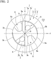
Fig. 2 is an enlarged front view of a front end surface of the drill main body shown inFig. 1 . -
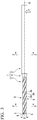
Fig. 3 is a side view as seen in the direction of arrow X inFig. 2 . -
Fig. 4 is a plan view as seen in the direction of arrow Y inFig. 2 . -
Fig. 5 is a cross-sectional view taken along YY inFig. 3 . -
Fig. 6 is a cross-sectional view taken along ZZ inFig. 3 . -
Fig. 7 is an enlarged cross-sectional view of a coolant hole on the right side inFig. 5 . -
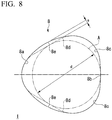
Fig. 8 is a cross-sectional view, corresponding to the enlarged cross-sectional view shown inFig. 7 , showing a modification example of the embodiment shown inFigs. 1 to 7 . -
Figs. 1 to 7 show an embodiment in a case where a rotating tool with a coolant hole of the present invention is applied to a drill with a coolant hole. In the present embodiment, a drill main body (rotating tool main body) 1 is integrally formed of a hard material such as cemented carbide in a substantially columnar shape having a multi-stage outer shape centered on an axis O. In the drillmain body 1, a rear portion (a right portion inFigs. 3 and4 ) having a larger outer diameter is used as ashank portion 2 having a columnar outer shape, and a front portion (a left portion inFig. 3 andFig. 4 ) formed to have one step smaller diameter than theshank portion 2 is used as acutting edge portion 3. - In such a drill with a coolant hole, as the
shank portion 2 is fed to a front side in the direction of the axis O while being gripped by a main spindle of a machine tool and rotated in a drill rotation direction (tool rotation direction ) T around the axis O, drilling is performed on a workpiece by acutting edge 5 formed on thecutting edge portion 3. In addition, in the present embodiment, a portion between theshank portion 2 and thecutting edge portion 3 of the drillmain body 1 is used as atapered neck portion 4 having an outer diameter gradually reduced in diameter in a constant proportion toward the front side of the drillmain body 1 and having a truncated cone shape centered on the axis O. - Two chip discharge flutes 6, which open to a front end surface of the drill
main body 1 and extend to be twisted to a side opposite to a drill rotation direction T toward a rear side are formed symmetrically with respect to the axis O at an outer periphery of thecutting edge portion 3 of the front portion of the drillmain body 1. Thecutting edge 5 is formed at a front side ridge portion of a wall surface of an inner wall face of each of the chip discharge flutes 6, which face the drill rotation direction T. Therefore, a front portion of the wall surface of eachchip discharge flute 6 facing the drill rotation direction T is used as a rake face of thecutting edge 5, and the front end surface of the drillmain body 1 connected to the rake face is used as atip flank face 7 of thecutting edge 5. In addition, the drillmain body 1 is 180° rotationally symmetrical with respect to the axis O. - The
tip flank face 7 includes first and second tip flank faces 7a and 7b in which a clearance angle gradually increases from thecutting edge 5 toward the side opposite to the drill rotation direction T. Additionally, thetip flank face 7 is inclined to face the rear side toward an outer peripheral side of the drillmain body 1, thereby giving a point angle to thecutting edge 5. Moreover, twomargin portions 3a connected to the drill rotation direction T side of thechip discharge flute 6 and the side opposite to the rotation direction T are formed on an outer peripheral surface of thecutting edge portion 3, and an outer peripheral flank face (body clearance) 3b is formed between the twomargin portions 3a. Moreover, aweb thinning portion 6a is formed on an inner peripheral portion of the tip of thechip discharge flute 6. - Additionally, in the drill
main body 1, twocoolant holes 8 having the same number as the chip discharge flutes 6 are formed from a rear end surface of theshank portion 2 toward the front side. The coolant holes 8 are twisted to the side opposite to the drill rotation direction T toward the rear side of the drillmain body 1 with a lead equal to thechip discharge flute 6 and are also formed symmetrically with respect to the axis O similar to thechip discharge flute 6. Each of the coolant holes 8 pass between the two chip discharge flutes 6 in thecutting edge portion 3 and opens to a secondtip flank face 7b of thetip flank face 7 on the front end surface of the drillmain body 1. - Also, as shown in
Fig. 7 , in a cross section orthogonal to the axis O, each of the coolant holes 8 is formed with a concavelycurved portion 8a located on an inner peripheral side of the drillmain body 1 and formed in a concavely curved shape recessed to the inner peripheral side, a second concavelycurved portion 8b located on an outer peripheral side of the drillmain body 1 so as to face the first concavelycurved portion 8a and formed in a concavely curved shape recessed to the outer peripheral side with a larger curvature radius r2 than a curvature radius r1 of the first concavelycurved portion 8a, two third concavelycurved portions 8c being in contact with two end portions of the concavelycurved portion 8b, extending toward a center side (axis O side) of the drillmain body 1 with a smaller curvature radius r3 than the second concavelycurved portion 8b, and being recessed in a circumferential direction, and twolinear portions 8d connecting an end portion of the first concavelycurved portion 8a to end portions of the third concavelycurved portion 8c that is not in contact with the second concavelycurved portion 8b. The center of the curvature radius r3 of each third concavelycurved portion 8c among these portions is inside thecoolant hole 8. - In the present embodiment, in the cross section orthogonal to the axis O, the first to third concavely
curved portions 8a to 8c of thecoolant hole 8 are all formed in a concave arc shape. Additionally, the curvature radii (radii) r3 of the two third concavelycurved portions 8c are made equal to each other, and the curvature radius (radius) r1 of the first concavelycurved portion 8a is also equal to the curvature radii (radii) r3 of the third concavelycurved portions 8c. Moreover, in the present embodiment, the twolinear portions 8d are straight lines as shown inFigs. 5 to 7 in the cross section orthogonal to the axis O, and extend such that extension lines thereof to the inner peripheral side of the drillmain body 1 intersect each other on the axis O. - Moreover, the second concavely
curved portion 8b has a concave arc shape centered on the axis O of the drillmain body 1. Moreover, in the cross section orthogonal to the axis O, thecoolant hole 8 has a symmetrical shape via a straight line connecting the axis O of the drillmain body 1 and a center C of the first concavelycurved portion 8a and is formed such that the width thereof in the circumferential direction gradually increases toward the outer peripheral side of the drillmain body 1 from the concavelycurved portion 8a to eachlinear portion 8d and the width thereof in the circumferential direction is gradually reduced toward the outer peripheral side from a tangential point between thelinear portion 8d and the third concavelycurved portion 8c. In addition, in the present embodiment, thelinear portion 8d is in contact with the first concavelycurved portion 8a and the third concavelycurved portion 8c. - Additionally, in the cross section orthogonal to the axis O, the first concavely
curved portion 8a is in contact with a circle E having a diameter D of thecutting edge 5 shown inFig. 3 about the axis O, that is, a radius B of 0.05 × D or more with respect to the diameter D of a circle formed around the axis O by an outer peripheral end of thecutting edge 5. In addition, it is desirable that the circle E centered on the axis O in contact with the first concavelycurved portion 8a has a radius B of 0.15 × D or more with respect to the diameter D of thecutting edge 5. Additionally, the curvature radius r2 of the second concavelycurved portion 8b is 0.42 × D or less with respect to the diameter D of thecutting edge 5. - In such a drill with a coolant hole, coolant such as cutting fluid, mist, or compressed air is supplied from the main spindle of the machine tool to the
coolant hole 8 during drilling and is discharged from an opening portion (secondtip flank face 7b) of the front end surface of the drillmain body 1. The coolant discharged from thecoolant hole 8 cools and lubricates thecutting edge 5 and a cutting portion of the workpiece by thecutting edge 5 and also flows through thechip discharge flute 6 toward the rear side of the drillmain body 1 to discharge the chips generated by thecutting edge 5. - Also, in the drill with a coolant hole having the above configuration, in the cross section orthogonal to the axis O of the drill
main body 1, thecoolant hole 8 is formed by the first to third concavelycurved portions 8a to 8c recessed to the outside of the coolant hole, and the twolinear portions 8d, and a convexly curved portion that is convex to the inside of thecoolant hole 8 is not formed. For this reason, as shown inFig. 7 , a diameter d of the circle A inscribed on thecoolant hole 8 can be increased in the cross section to secure the cross-sectional area of thecoolant hole 8. Moreover, since the first concavelycurved portion 8a can be located on the inner peripheral side of the drillmain body 1 via thelinear portion 8d, the coolant can be sufficiently supplied to the inner peripheral side of the drillmain body 1. - Therefore, according to the coolant drill with a coolant hole of the above configuration, the pressure loss of the coolant can be suppressed even in, for example, a drill in which the diameter D of the
cutting edge 5 is small. For this reason, the coolant can be discharged from thecoolant hole 8 at a sufficient discharge flow rate, and smooth discharge of the chips and effective cooling and lubrication of thecutting edge 5 can be achieved to prevent chip clogging and extend the life of the drillmain body 1. - Additionally, as described above, the convexly curved portion that is convex to the inside of the coolant holes 8 in the cross section orthogonal to the axis O is not formed in the
coolant bore 8. Therefore, unlike a case where a convexly curved portion is formed at a corner portion of such a convexly curved portion, the curvature radius of the concavely curved portion does not become smaller. That is, the curvature radii r1 and r3 of the first and third concavelycurved portions curved portions curved portions 8a and 8C at the stage of material molding or the like can be prevented. - Moreover, in the present embodiment, the curvature radius r1 of the first concavely
curved portion 8a and the curvature radius r3 of the two third concavelycurved portions 8c are equal to each other. For this reason, unlike a case where, in thecoolant hole 8 having a constant cross-sectional area, the curvature radius of any one or two concavely curved portions among the curvature radius r1 of the first concavelycurved portion 8a and the curvature radius r3 of the two third concavelycurved portions 8c are extremely larger than the curvature radius of the other concavely curved portion, it is not necessary to extremely reduce the curvature radius of the other concavely curved portion. Therefore, it is possible to reliably prevent a crack from being generated from the other concavely curved portion. - In addition, it is desirable that a ratio rl/r3 of the curvature radius r1 of the first concavely
curved portion 8a to the curvature radius r3 of the two third concavelycurved portions 8c is in a range of 0.5 to 2.0 because an extreme size is not caused. Additionally, the curvature radius r3 of the two third concavelycurved portions 8c may also be different from each other as long as the ratio is within this range. - Moreover, in the present embodiment, the first concavely
curved portion 8a is in contact with the circle E having the radius B of 0.05 × D or more with respect to the diameter D of thecutting edge 5 about the axis O in the cross section orthogonal to the axis O. For this reason, there is no concern that damage to the drillmain body 1 occurs in a case where the spacing between thecoolant hole 8 and the axis O of the drillmain body 1 becomes too small and an excessive load acts on thecutting edge portion 3. In addition, in order to reliably prevent damage to such a drillmain body 1, as described above, it is more desirable that the first concavely curved portion is in contact with the circle having the radius B of 0.15 × D or more with respect to the diameter D of thecutting edge 5 about the axis O in the cross section orthogonal to the axis O. - Additionally, in the present embodiment, the curvature radius r2 of the second concavely
curved portion 8b is 0.42 × D or less with respect to the diameter D of thecutting edge 5 in the cross section orthogonal to the axis O. For this reason, it is also possible to prevent a situation in which damage to the drillmain body 1 occurs because at least one of the two third concavely curved portions 3c in contact with both ends of the second concavelycurved portion 8b via thelinear portions 8d is too close to the outer peripheral surface of thecutting edge portion 3 of the drillmain body 1 and the spacing (wall thickness) between this outer peripheral surface and thecoolant hole 8 becomes too small. - In addition, in the present embodiment, as described above, the
linear portions 8d are straight lines in the cross section orthogonal to the axis O. However, the linear portions may belinear portions 8e having a substantially linear shape, such as concave curves bulging with respect to the twolinear portions 8d, which are straight lines, and having a large curvature radius, for example, as in a modification example of the above embodiment shown inFig. 8 , unless the linear portions are formed in a convex curve shape that is convex to the inside of the coolant hole in the cross section orthogonal to the axis of the drill main body, as in the forward hole wall surface and the backward hole wall surface of the drill with a coolant hole described inPatent Document 1. - Even in the rotating tool (drill) with a coolant hole of such a modification example, the convexly curved portion that is convex to the inside of the
coolant hole 8 is not formed in thecoolant hole 8 in the cross section orthogonal to the axis O. Therefore, the cross-sectional area of thecoolant hole 8 can be secured. Therefore, even in the drill in which the diameter D of thecutting edge 5 is small, the pressure loss of the coolant can be suppressed, and smooth discharge of the chips and effective cooling and lubrication of the cutting edge 5y can be achieved to prevent chip clogging and extend the life of the drillmain body 1. - However, when the
linear portions 8e that are substantially linear bulge excessively largely with respect to thelinear portions 8d that are straight lines, there is a concern that the spacing (wall thickness) between thelinear portion 8e and the wall surface of the inner wall face of thechip discharge flute 6 facing the drill rotation direction T or the wall surface of the inner wall face facing the side opposite to the drill rotation direction T becomes smaller and damage occurs in the drillmain body 1. For this reason, as shown inFig. 8 , in the cross section orthogonal to the axis O, a maximum protruding amount (bulging amount) e by which thelinear portions 8e that are substantially linear bulge with respect to thelinear portions 8d that are straight lines is in a range of 5% or less of a diameter d of the circle (the circle in contact with the second concavelycurved portion 8b and the twolinear portion portions 8d that are straight lines) A inscribed on thecoolant hole 8 of the twolinear potions 8d that are straight lines. - Additionally, in the present embodiment, a case where the present invention is applied to the drill with a coolant hole has been described. However, the present invention can also be applied to a reamer or an end mill that is the same rotating tool. In particular, in a case where the present invention is applied to the end mill, the coolant hole may open to the inner wall face of the chip discharge flute.
- Moreover, in the present embodiment, a case where the present invention is applied to the drill with a coolant hole (a rotating tool with a coolant hole) in which the
cutting blades 5, the chip discharge flutes 6, and the coolant holes 8 are two, respectively, has been described. However, it is of course possible to apply the present invention to a rotating tool with a coolant hole in which a cutting edge, a groove, and a coolant hole are one, respectively, and a rotating tool with a coolant hole in which cutting edges, chip discharge flutes, and coolant holes are three or more, respectively. Additionally, the number of coolant holes may be different from the number of cutting edges and the number of chip discharge flutes. - According to the present invention, the generation of a crack from the coolant hole at the stage of material molding or the like can be prevented, a sufficient discharge flow rate of the coolant can be secured, chip clogging can be prevented by improving chip discharge performance, and the life of the tool can be extended by effectively cooling and lubricating the cutting edge.
-
- 1: Drill main body (rotating tool main body)
- 2: Shank portion
- 3: Cutting edge portion
- 4: Tapered neck portion
- 5: Cutting edge
- 6: Chip discharge flute
- 7: Tip flank face
- 8: Coolant hole
- 8a: First concavely curved portion
- 8b: Second concavely curved portion
- 8c: Third concavely curved portion
- 8d, 8e: Linear portion
- O: Axis of drill
main body 1 - T: Drill rotation direction (tool rotation direction)
- r1: Curvature radius of first concavely
curved portion 8a - r2: Curvature radius of second concavely
curved portion 8b - r3: Curvature radius of third concavely
curved portion 8c - A: Circle inscribed on
coolant hole 8 - d: Diameter of circle A
- C: Center of first concavely
curved portion 8a - D: Diameter of cutting
edge 5 - E: Circle in contact with first concavely
curved portion 8a centered on axis O in cross section orthogonal to axis O - B: Radius of circle E
- e: Maximum protruding amount (bulging amount) of
linear portion 8e having concavely curved shape with respect tolinear portion 8d that is straight line
Claims (4)
- A rotating tool with a coolant hole, comprising:a rotating tool main body configured to be rotated in a tool rotation direction around an axis,wherein a chip discharge flute that opens to a front end surface of the rotating tool main body and extends to a rear side is formed at an outer periphery of a front portion of the rotating tool main body,a cutting edge, in which a wall surface of an inner wall face of the chip discharge flute facing the tool rotation direction is used as a rake face and the front end surface of the rotating tool main body connected to the rake face is used as a tip flank face, is formed at a front side ridge portion of the wall surface,a coolant hole that extends toward a front side in an axis direction in the rotating tool main body opens to at least one of the tip flank face and the inner wall face of the chip discharge flute,in a cross section orthogonal to the axis, the coolant hole is provided with,a first concavely curved portion located on an inner peripheral side of the rotating tool main body and formed in a concavely curved shape recessed to the inner peripheral side,a second concavely curved portion located on an outer peripheral side of the rotating tool main body so as to face the first concavely curved portion and formed in a concavely curved shape recessed to the outer peripheral side with a larger curvature radius than a curvature radius of the first concavely curved portion,two third concavely curved portions being in contact with two end portions of the second concavely curved portion, respectively, having a center of a curvature radius located inside the coolant hole with a smaller curvature radius than that of the second concavely curved portion, extending to a center side of the rotating tool main body, and being recessed in a circumferential direction, andtwo linear portions connecting an end portion of the first concavely curved portion to the end portion of the third concavely curved portion that is not in contact with the second concavely curved portion.
- The rotating tool with a coolant hole according to Claim 1,
wherein a ratio r1/r3 of a curvature radius r1 of the first concavely curved portion to a curvature radius r3 of the two third concavely curved portions is in a range of 0.5 to 2.0. - The rotating tool with a coolant hole according to Claim 1 or 2,
wherein the first concavely curved portion is in contact with a circle having a radius of 0.05 × D or more with respect to a diameter D of the cutting edge about the axis in the cross section orthogonal to the axis. - The rotating tool with a coolant hole according to any one of Claims 1 to 3,
wherein a curvature radius of the second concavely curved portion is 0.42 × D or less with respect to a diameter D of the cutting edge in the cross section orthogonal to the axis.
Applications Claiming Priority (3)
| Application Number | Priority Date | Filing Date | Title |
|---|---|---|---|
| JP2018242586 | 2018-12-26 | ||
| JP2019198973A JP7463689B2 (en) | 2018-12-26 | 2019-10-31 | Rotary tools with coolant holes |
| PCT/JP2019/050266 WO2020137937A1 (en) | 2018-12-26 | 2019-12-23 | Rotating tool with coolant hole |
Publications (2)
| Publication Number | Publication Date |
|---|---|
| EP3903976A1 true EP3903976A1 (en) | 2021-11-03 |
| EP3903976A4 EP3903976A4 (en) | 2022-09-14 |
Family
ID=71447791
Family Applications (1)
| Application Number | Title | Priority Date | Filing Date |
|---|---|---|---|
| EP19905782.9A Pending EP3903976A4 (en) | 2018-12-26 | 2019-12-23 | Rotating tool with coolant hole |
Country Status (3)
| Country | Link |
|---|---|
| EP (1) | EP3903976A4 (en) |
| JP (1) | JP7463689B2 (en) |
| CN (1) | CN113226606B (en) |
Cited By (3)
| Publication number | Priority date | Publication date | Assignee | Title |
|---|---|---|---|---|
| CN115476490A (en) * | 2022-09-29 | 2022-12-16 | 唐飞鹏 | Spot cooling spray pipe, processing method and mold cooling device including same |
| CN117206573A (en) * | 2022-06-09 | 2023-12-12 | 株式会社泰珂洛 | Drill bit body and manufacturing method thereof |
| CN119016766A (en) * | 2024-10-23 | 2024-11-26 | 株洲钻石切削刀具股份有限公司 | Internally cooled drill bit |
Families Citing this family (2)
| Publication number | Priority date | Publication date | Assignee | Title |
|---|---|---|---|---|
| US20240367239A1 (en) * | 2021-05-10 | 2024-11-07 | Osg Corporation | Drill |
| JPWO2024111092A1 (en) | 2022-11-24 | 2024-05-30 |
Family Cites Families (15)
| Publication number | Priority date | Publication date | Assignee | Title |
|---|---|---|---|---|
| DE3629035A1 (en) * | 1986-08-27 | 1988-03-10 | Stellram Gmbh | ONE-PIECE CUTTING TOOL |
| DE10394165D2 (en) * | 2002-12-19 | 2005-11-03 | Guehring Joerg | Coiled cooling channels |
| DE20219824U1 (en) * | 2002-12-19 | 2004-04-29 | Gühring, Jörg, Dr. | Rotary machining tool such as drill for drilling holes has minimum wall thicknesses between defined upper and lower limits |
| DE102008004564B4 (en) * | 2008-01-15 | 2013-04-11 | EMUGE-Werk Richard Glimpel GmbH & Co. KG Fabrik für Präzisionswerkzeuge | Burr tool with point |
| CN201253702Y (en) * | 2008-09-19 | 2009-06-10 | 株洲钻石切削刀具股份有限公司 | Spiral bit with coolant passage |
| JP5447129B2 (en) * | 2009-06-15 | 2014-03-19 | 三菱マテリアル株式会社 | Drill with coolant hole |
| CN202278228U (en) * | 2011-10-26 | 2012-06-20 | 株洲钻石切削刀具股份有限公司 | Integral twist drill for processing titanium alloy |
| JP5939001B2 (en) * | 2012-01-16 | 2016-06-22 | 三菱日立ツール株式会社 | drill |
| JP2013188843A (en) * | 2012-03-14 | 2013-09-26 | Mitsubishi Materials Corp | Ball end mill comprising coolant hole |
| WO2014118881A1 (en) * | 2013-01-29 | 2014-08-07 | オーエスジー株式会社 | Drill |
| DE102013205056A1 (en) * | 2013-03-21 | 2014-09-25 | Gühring KG | Multi-bladed drilling tool with internal cooling channels |
| JP6589462B2 (en) * | 2015-08-27 | 2019-10-16 | 三菱マテリアル株式会社 | Drill |
| CN205129020U (en) * | 2015-11-02 | 2016-04-06 | 深圳市航天精密刀具有限公司 | A internal cooling carbide drill bit for BTA |
| CH712323A1 (en) * | 2016-04-07 | 2017-10-13 | Mikron Tool Sa Agno | Machining tool with at least one cooling channel. |
| JP6848160B2 (en) * | 2016-05-19 | 2021-03-24 | 住友電工ハードメタル株式会社 | Cutting tools |
-
2019
- 2019-10-31 JP JP2019198973A patent/JP7463689B2/en active Active
- 2019-12-23 EP EP19905782.9A patent/EP3903976A4/en active Pending
- 2019-12-23 CN CN201980085869.1A patent/CN113226606B/en active Active
Cited By (3)
| Publication number | Priority date | Publication date | Assignee | Title |
|---|---|---|---|---|
| CN117206573A (en) * | 2022-06-09 | 2023-12-12 | 株式会社泰珂洛 | Drill bit body and manufacturing method thereof |
| CN115476490A (en) * | 2022-09-29 | 2022-12-16 | 唐飞鹏 | Spot cooling spray pipe, processing method and mold cooling device including same |
| CN119016766A (en) * | 2024-10-23 | 2024-11-26 | 株洲钻石切削刀具股份有限公司 | Internally cooled drill bit |
Also Published As
| Publication number | Publication date |
|---|---|
| EP3903976A4 (en) | 2022-09-14 |
| CN113226606B (en) | 2024-09-13 |
| JP2020104253A (en) | 2020-07-09 |
| JP7463689B2 (en) | 2024-04-09 |
| CN113226606A (en) | 2021-08-06 |
Similar Documents
| Publication | Publication Date | Title |
|---|---|---|
| US10471522B2 (en) | Drill | |
| KR101369613B1 (en) | Drill with coolant holes | |
| CN104718039B (en) | Slotting cutter with Cooling Holes | |
| JP5762547B2 (en) | drill | |
| US9028179B2 (en) | Drilling tool | |
| US9511424B2 (en) | Drill | |
| JP7463689B2 (en) | Rotary tools with coolant holes | |
| EP3199279A1 (en) | Drill and drill head | |
| US9352399B2 (en) | Drill | |
| JP6108264B2 (en) | 2-flute double margin drill | |
| KR20090117659A (en) | Drill body | |
| EP3037197B1 (en) | Drill | |
| WO2010050391A1 (en) | Ball end mill | |
| US20220266352A1 (en) | Drill | |
| US12576452B2 (en) | Drill | |
| US12303986B2 (en) | Rotating tool with coolant hole | |
| US11992887B2 (en) | Drill | |
| US12083605B2 (en) | Cutting tool | |
| WO2025105312A1 (en) | Drill |
Legal Events
| Date | Code | Title | Description |
|---|---|---|---|
| STAA | Information on the status of an ep patent application or granted ep patent |
Free format text: STATUS: THE INTERNATIONAL PUBLICATION HAS BEEN MADE |
|
| PUAI | Public reference made under article 153(3) epc to a published international application that has entered the european phase |
Free format text: ORIGINAL CODE: 0009012 |
|
| STAA | Information on the status of an ep patent application or granted ep patent |
Free format text: STATUS: REQUEST FOR EXAMINATION WAS MADE |
|
| 17P | Request for examination filed |
Effective date: 20210624 |
|
| AK | Designated contracting states |
Kind code of ref document: A1 Designated state(s): AL AT BE BG CH CY CZ DE DK EE ES FI FR GB GR HR HU IE IS IT LI LT LU LV MC MK MT NL NO PL PT RO RS SE SI SK SM TR |
|
| DAV | Request for validation of the european patent (deleted) | ||
| DAX | Request for extension of the european patent (deleted) | ||
| A4 | Supplementary search report drawn up and despatched |
Effective date: 20220817 |
|
| RIC1 | Information provided on ipc code assigned before grant |
Ipc: B23B 51/06 20060101ALI20220810BHEP Ipc: B23D 77/00 20060101ALI20220810BHEP Ipc: B23C 5/28 20060101AFI20220810BHEP |
|
| STAA | Information on the status of an ep patent application or granted ep patent |
Free format text: STATUS: EXAMINATION IS IN PROGRESS |
|
| 17Q | First examination report despatched |
Effective date: 20230504 |