EP3903939A1 - Gene amplification module - Google Patents
Gene amplification module Download PDFInfo
- Publication number
- EP3903939A1 EP3903939A1 EP20740902.0A EP20740902A EP3903939A1 EP 3903939 A1 EP3903939 A1 EP 3903939A1 EP 20740902 A EP20740902 A EP 20740902A EP 3903939 A1 EP3903939 A1 EP 3903939A1
- Authority
- EP
- European Patent Office
- Prior art keywords
- heat block
- amplification module
- gene amplification
- empty space
- heat
- Prior art date
- Legal status (The legal status is an assumption and is not a legal conclusion. Google has not performed a legal analysis and makes no representation as to the accuracy of the status listed.)
- Pending
Links
Images




Classifications
-
- B—PERFORMING OPERATIONS; TRANSPORTING
- B01—PHYSICAL OR CHEMICAL PROCESSES OR APPARATUS IN GENERAL
- B01L—CHEMICAL OR PHYSICAL LABORATORY APPARATUS FOR GENERAL USE
- B01L7/00—Heating or cooling apparatus; Heat insulating devices
- B01L7/52—Heating or cooling apparatus; Heat insulating devices with provision for submitting samples to a predetermined sequence of different temperatures, e.g. for treating nucleic acid samples
-
- B—PERFORMING OPERATIONS; TRANSPORTING
- B01—PHYSICAL OR CHEMICAL PROCESSES OR APPARATUS IN GENERAL
- B01L—CHEMICAL OR PHYSICAL LABORATORY APPARATUS FOR GENERAL USE
- B01L2200/00—Solutions for specific problems relating to chemical or physical laboratory apparatus
- B01L2200/06—Fluid handling related problems
- B01L2200/0647—Handling flowable solids, e.g. microscopic beads, cells, particles
- B01L2200/0663—Stretching or orienting elongated molecules or particles
-
- B—PERFORMING OPERATIONS; TRANSPORTING
- B01—PHYSICAL OR CHEMICAL PROCESSES OR APPARATUS IN GENERAL
- B01L—CHEMICAL OR PHYSICAL LABORATORY APPARATUS FOR GENERAL USE
- B01L2300/00—Additional constructional details
- B01L2300/08—Geometry, shape and general structure
- B01L2300/0848—Specific forms of parts of containers
- B01L2300/0858—Side walls
-
- B—PERFORMING OPERATIONS; TRANSPORTING
- B01—PHYSICAL OR CHEMICAL PROCESSES OR APPARATUS IN GENERAL
- B01L—CHEMICAL OR PHYSICAL LABORATORY APPARATUS FOR GENERAL USE
- B01L2300/00—Additional constructional details
- B01L2300/18—Means for temperature control
- B01L2300/1805—Conductive heating, heat from thermostatted solids is conducted to receptacles, e.g. heating plates, blocks
-
- B—PERFORMING OPERATIONS; TRANSPORTING
- B01—PHYSICAL OR CHEMICAL PROCESSES OR APPARATUS IN GENERAL
- B01L—CHEMICAL OR PHYSICAL LABORATORY APPARATUS FOR GENERAL USE
- B01L2300/00—Additional constructional details
- B01L2300/18—Means for temperature control
- B01L2300/1894—Cooling means; Cryo cooling
-
- C—CHEMISTRY; METALLURGY
- C12—BIOCHEMISTRY; BEER; SPIRITS; WINE; VINEGAR; MICROBIOLOGY; ENZYMOLOGY; MUTATION OR GENETIC ENGINEERING
- C12Q—MEASURING OR TESTING PROCESSES INVOLVING ENZYMES, NUCLEIC ACIDS OR MICROORGANISMS; COMPOSITIONS OR TEST PAPERS THEREFOR; PROCESSES OF PREPARING SUCH COMPOSITIONS; CONDITION-RESPONSIVE CONTROL IN MICROBIOLOGICAL OR ENZYMOLOGICAL PROCESSES
- C12Q1/00—Measuring or testing processes involving enzymes, nucleic acids or microorganisms; Compositions therefor; Processes of preparing such compositions
- C12Q1/68—Measuring or testing processes involving enzymes, nucleic acids or microorganisms; Compositions therefor; Processes of preparing such compositions involving nucleic acids
- C12Q1/6844—Nucleic acid amplification reactions
Definitions
- the present invention relates to a gene amplification module that is capable of quickly heating and cooling a specimen within a reaction container when compared to the prior art.
- a gene amplification module for nucleic acid amplification is essential for genetic diagnosis to obtain various biological information in a specimen. That is, when the gene is diagnosed, a specific gene within the specimen collected by the gene amplification module is amplified to increase in number of genes within the specimen, and then, a degree of amplification of the specific gene is confirmed to obtain desired biological information.
- the gene amplification is performed by repeatedly adjusting a temperature. More particularly, the specimen periodically increases and descends in temperature at regular time intervals to amplify the gene of the specimen.
- An object of the present invention for solving the above problem is to reduce a time taken to amplify a gene of a specimen so as to reduce a time taken to diagnose the gene.
- a gene amplification module including: a heat block in which a reaction container accommodation space for accommodating a reaction container containing a specimen to be amplified is defined; a heating part provided below the heat block to heat the heat block by being heat-exchanged with the heat block through thermal conduction; a cooling part provided below the heating part to cool the heat block by being heat-exchanged with the heating part through thermal conduction; a fluid supply part provided to face one side of the heat block, the fluid supply part being configured to supply a cooling fluid to the heat block, wherein sidewalls defining a circumference of the heat block are provided on the heat block, and one or more supply holes configured to supply the cooling fluid are defined in the sidewalls.
- An empty space may be defined in the heat block, and the empty space may communicate with the supply holes.
- total m x n reaction container accommodation spaces may be defined in an m x n matrix form (where m and n are natural numbers different from each other), or total n 2 reaction container accommodation spaces may be defined in an n x n matrix form, and the supply holes may be defined between the reaction container accommodation spaces, respectively.
- the fluid supply part may include: a first fluid supply part provided to face the sidewall of the heat block in which the supply holes are defined; and a second fluid supply part provided to face the other sidewall of the heat block in which the supply holes are defined.
- the fluid supply part may be provided in close contact with the sidewall, in which the supply holes are defined, among the sidewalls.
- the empty space may be spaced apart from the reaction container accommodation space.
- the empty space may include: a first empty space communicating with the supply holes; and a second empty space defined to cross the first empty space.
- Discharge holes communicating with the second empty space may be defined in the sidewalls of the heat block.
- the discharge holes may be defined in both ends of the second empty space, respectively.
- the fluid supply part may include a rotatable fan to allow the cooling fluid to be supplied into the empty space of the heat block.
- the method for cooling the specimen may be additionally performed to increase in cooling speed when compared to the method according to the related art.
- the time taken to amplify the gene of the specimen may be reduced to reduce the time taken to diagnose the gene.
- FIG. 1 is a perspective view illustrating an example of a structure of a heat block of a gene amplification module according to the present invention
- FIG. 2 is a horizontal cross-sectional view illustrating an example of the structure of the heat block of the gene amplification module according to the present invention
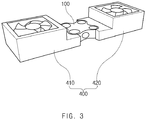
- FIG. 3 is a perspective view illustrating a coupling relationship between the heat block and a fluid supply part in the gene amplification module according to the present invention.
- a gene amplification module may include a heat block 100.
- the heat block 100 may be configured to accommodate a specimen to be amplified.
- the specimen may be periodically heated and cooled by heat transfer of the heat block 100 to amplify a gene of the specimen accommodated in the heat block 100.
- the heat block 100 may be made of a material having high thermal conductivity such as gold, silver, copper, an alloy, aluminum, and the like.
- the heat block 100 may be made of aluminum.
- a reaction container accommodation space R for accommodating a reaction container (not shown) in which a specimen to be amplified is provided may be defined in the heat block 100.
- FIG. 1 illustrates a case in which total four reaction container accommodation spaces R are defined in the heat block 100 in a 2 x 2 matrix form.
- the reaction container may be made of a plastic material.
- a sidewall 110 defining a circumference of the heat block 100 may be disposed on the heat block 100.
- FIG. 1 illustrates a case in which four sidewalls, each of which has a curved surface having a wave shape, are provided.
- the heat block 100 may be minimized in weight to reduce heat capacity thereof, thereby minimizing heating and cooling rates thereof when compared to a case in which four planes meet each other to form the sidewalls of the heat block.
- each of the sidewalls defining a circumference of the heat block 100 according to the present invention may have various shapes in addition to the wave shape. That is, the shape of the sidewall of the heat block 100 according to the present invention is not limited to the wave shape.
- At least one or more holes may be defined in the sidewalls of the heat block 100.
- the holes defined in the heat block 100 may be configured to supply and discharge a cooling fluid for cooling the heated heat block 100.
- a supply hole SH to which the cooling fluid is supplied may be defined in a portion of the sidewalls 110 of the heat block 100
- a discharge hole DH through which the cooling fluid is discharged to the outside may be defined in the other portion of the sidewalls 110 of the heat block 100.
- the cooling fluid may be a gas.
- the cooling fluid may be air at room temperature.
- an empty space V may be defined in the heat block 100.
- the empty space V may communicate with the supply hole SH and the discharge hole DH.
- the empty space V may provide a path through which the cooling fluid supplied to the heat block 100 flows.
- Two supply holes SH may be provided.
- the supply holes SH may be defined at sides opposite to each other with the empty space V therebetween.
- the empty space V defined in the heat block 100 may do not communicate with the reaction container accommodation space R but be spaced apart from the reaction container accommodation space R.
- the reaction container containing the specimen to be amplified may be accommodated in the reaction container accommodation space R.
- an inner wall defining the reaction container accommodation space R may not sufficiently surround the reaction container.
- the reaction container accommodation space R does not communicate with the empty space V so that the specimen is quickly heated or cooled by the heat block 100.
- the empty space V defined in the heat block 100 may include a first empty space V1 and a second empty space V2.
- the first empty space V1 may have both ends which are respectively connected to the supply holes SH.
- the second empty space V2 may defined to cross the first empty space V1.
- holes may be further defined in the sidewalls of the heat block 100 in addition to the supply holes SH. That is, as illustrated in FIG. 2 , discharge holes DH may be further defined in the sidewalls of the heat block 100.
- FIG. 2 illustrates a case in which the discharge holes DH are respectively defined one by one in the sidewalls disposed at left and right sides of the heat block 100.
- the discharge holes DH may communicate with the second empty space V2.
- the discharge hole DH may also be provided in plurality.
- the discharge holes DH may be defined in both ends of the second empty space V2.
- the gene amplification module according to the present invention may further include a fluid supply part 400 disposed to face one of the sidewalls of the heat block 100 and supply the cooling fluid to the heat block 100.
- the fluid supply part 400 may face the sidewall in which the supply hole SH (see FIG. 2 ) is defined.
- the fluid supply part 400 may supply the cooling fluid to the empty space V (see FIG. 2 ) within the heat block 100 through the supply hole.
- the fluid supply part 400 of the gene amplification module according to the present invention may be provided in plurality.
- the fluid supply part 400 may be provided as many as the number of supply holes SH (see FIG. 2 ).
- FIG. 3 illustrates a first fluid supply part 410 disposed to face the sidewall of the heat block 100, in which one of the two supply holes defined in the heat block 100 is defined, and a second fluid supply part 420 disposed to face the sidewall of the heat block 100, in which the other one of the two supply holes defined in the heat block 100 is defined.
- the fluid supply part 400 may include a rotatable fan so that the cooling fluid is supplied to the empty space of the heat block 100.
- the fluid supply part 400 may be disposed in close contact with the sidewall in which the supply hole SH (see FIG. 2 ) is defined. Thus, leakage of the cooling fluid from the fluid supply part 400 to other portions except for the heat block 100 may be minimized.
- the supply hole SH (see FIG. 2 ) and the discharge hole DH (see FIG. 2 ) may be defined in the heat block 100.
- the gene amplification module may further include a fluid discharge part (not shown) that is disposed to face the discharge hole and discharges the cooling fluid within the heat block 100 to the outside through the discharge hole.
- FIG. 4 is a perspective view illustrating a structure of the gene amplification module according to the present invention.
- the gene amplification module 10 may include the heat block and the fluid supply part 400.
- the gene amplification module 10 may include a heating part 200 that is provided below the heat block 200 to heat the heat block 100.
- the heat part 200 may contact the heat block 100.
- the heating part 200 may be heat-exchanged with the heat block 100 through heat conduction.
- the heating part 200 according to the present invention may be configured to the heat block 100 by a local temperature increase due to the Peltier effect.
- the Peltier effect refers to a phenomenon in which a temperature difference occurs at both sides due to movement of thermal energy together with current when a voltage is applied to both the sides of an object.
- the heating part according to the present invention may be configured to heat the heat block through the Peltier effect.
- the gene amplification module according to the present invention may further include a cooling part 300 disposed below the heating part 200 to cool the heat block 100.
- the cooling part 300 may contact the heating part 200.
- the cooling part 300 may cool the heat block 100 by heat-exchange between the cooling part 300 and the heating part 200 through thermal conduction and heat-exchange between the heating part 200 and the heat block 100.
- the cooling part 300 according to the present invention may be a heat sink having a lower temperature and a significantly higher heat capacity than the heat block 100 and the heating part 200.
- the heat block 100 When the reaction container containing a specimen within the reaction container accommodation space R of the heat block 100 is disposed, and then, the heating part 200 operates to increase in temperature thereof, the heat block 100 may increase in temperature by the heat-exchange between the heat block 100 and the heating part 200 through the thermal conduction, and thus, the specimen within the reaction container may also increase in temperature.
- the heat block 100 may decrease in temperature by the heat-exchange between the cooling part 300 and the heating part 200 through the thermal conduction and the heat-exchange between the heating part 200 and the heat block 100 through the thermal conduction, and thus, the specimen within the reaction container may also decrease in temperature.
- the cooling fluid since the cooling fluid is supplied to the empty space V of the heat block 100 through the supply hole SH of the heat block 100 through the fluid supply part 400 together with the operation of the cooling part 300, the cooling fluid may additionally cool the heat block 100. Therefore, the heat block 100 and the specimen may be more quickly cooled to significantly reduce the overall time required for the amplification process of the specimen.
- FIG. 5 is a perspective view illustrating another example of the structure of the heat block of the gene amplification module according to the present invention
- FIG. 6 is a horizontal cross-sectional view illustrating another example of the structure of the heat block of the gene amplification module according to the present invention.
- total four reaction container accommodation spaces may be defined in a 2 x 2 matrix form.
- the heat block may have a different structure.
- total nine reaction container accommodation spaces R may be defined in a 3 x 3 matrix form.
- total nine reaction container accommodation spaces R may be defined in a 4 x 4 matrix form.
- total n 2 reaction container accommodation spaces may be defined in an n x n matrix form.
- total m x n reaction container accommodation spaces may be defined in an m x n matrix form (where m and n are natural numbers different from each other).
- total six reaction container accommodation spaces may be defined in a 2 x 3 matrix form.
- a plurality of supply holes SH and discharge holes DH may be defined in the sidewalls defining the circumference of the heat block 100.
- two supply holes SH may be defined in each of two sidewalls defined at opposite sides with the first empty space V1, which is defined in the heat block 100, therebetween, and thus, total four supply holes SH may be defined in the heat block 100.
- total four supply holes SH may be defined in the heat block 100.
- n-1 supply holes may be defined at each of two sidewalls defined at opposite sides with the first empty space of the heat block 100 therebetween, and thus, total 2 x (n-1) supply holes may be defined in the heat block 100.
- n-1 discharge holes may be defined at each of two sidewalls defined at opposite sides with the second empty space of the heat block 100 therebetween, and thus, total 2 x (n-1) discharge holes may be defined in the heat block 100.
- total m x n reaction container communication spaces may be defined in an m x n matrix form (where m and n are natural numbers different from each other).
- m-1 supply holes may be defined in each of two sidewalls disposed at opposite sides with the first empty space of the heat block therebetween, and thus, total 2 x (m-1) supply holes may be defined in the heat block.
- n-1 discharge holes may be defined in each of two sidewalls disposed at opposite sides with the second empty space of the heat block therebetween, and thus, total 2 x (n-1) discharge holes may be defined in the heat block.
- this structure in which the m-1 supply holes are defined in each of the two sidewalls disposed at the opposite sides with the first empty space of the heat block therebetween, and the n-1 discharge holes are defined in the two sidewall disposed at the opposite sides with the second empty space of the heat block therebetween, is because the supply holes SH and the discharge holes DH are respectively defined between the reaction container accommodation spaces R as illustrated in FIGS. 5 and 6 .
- the supply holes SH defined at the opposite sides with the first empty space V1 therebetween and the discharge holes DH defined at the opposite sides with the second empty space V2 therebetween may communicate with the first empty space V1 and the second empty space V2, respectively.
- a heat block having a length of 16 mm and a width of 16 mm was prepared.
- Each of four sidewalls of the heat block had a curved surface having a wave shape, and total four reaction container accommodation spaces were defined in a 2 x 2 matrix form in the heat block.
- Each of the reaction container accommodation spaces had a diameter of 4.5 mm.
- the heat block was made of aluminum.
- Holes each of which has a diameter of 4.8 mm, were defined one by one in the four sidewalls of the heat block, and an empty space having a cross (+) shape was defined in the heat block. The holes communicated with each other by the empty space.
- thermoelectric element A Pelitier-based heating part that is thermoelectric element was provided below the heat block.
- the product name VT-127-1.4-1.15-71 manufactured by TE technology, INC, USA was used as the heating unit that is a thermoelectric element configured to heat the heat block by the Peltier effect.
- a cooling part was disposed in close contact with a lower portion of the heating part.
- the cooling part was provided as a heat sink that is capable of absorbing heat.
- a blowing fan was installed on a lower end of the heat sink to reduce a temperature of the heat sink.
- the product name CTV-GF-04 manufactured by Coolertech of Korea was used as the heat sink and the blowing fan.
- a fluid supply part was disposed in close contact with each of two sidewalls facing each other at opposite sides among the four sidewalls of the heat block.
- the fluid supply part was configured to supply a cooling fluid to the empty space of the heat block by driving the fan.
- the product name HFD 0200605 SEM, B-type manufactured by YeHAUS, China was used as the fan constituting the fluid supply part.
- the heating part operated under a voltage of 14.8 V and current of 5 A to heat the heat block until a temperature of the heat block reaches 95 degrees Celsius, and then, the operation of the heating part was stopped, and the fluid supply part operated under conditions of 11.1 V, 0.28 A, and 3.1 W until the temperature of the heat block reaches 60 degrees Celsius by the cooling fluid and the cooling part installed on the lower end.
- the blowing fan installed on the lower end of the heat sink operated to reduce a temperature of the heat sink, and thus, a gradient was generated between the heat block and the heat sink to cool the heat block.
- the heating and cooling processes were repeated.
- Embodiment 2 was performed in the same manner as in Embodiment 1 except that the fluid supply part operated under conditions of 7.4 V, 0.21 V and 1.5 W to cool the heat block until the temperature of the heat block reaches 60 degrees Celsius.
- Comparative Example was performed in the same manner as in Embodiment 1 except that the fluid supply part is not provided.
- Embodiment 1 it was taken 602 seconds to complete the thirty heating and cooling processes, and in the case of Embodiment 2, it was taken 674 seconds to complete the thirty heating and cooling processes. In the case of Comparative Example, it was taken 840 seconds to complete the thirty heating and cooling processes.
Landscapes
- Health & Medical Sciences (AREA)
- Chemical & Material Sciences (AREA)
- Life Sciences & Earth Sciences (AREA)
- Biochemistry (AREA)
- General Health & Medical Sciences (AREA)
- Molecular Biology (AREA)
- Clinical Laboratory Science (AREA)
- Chemical Kinetics & Catalysis (AREA)
- Apparatus Associated With Microorganisms And Enzymes (AREA)
- Measuring Or Testing Involving Enzymes Or Micro-Organisms (AREA)
Abstract
Description
- The present application claims the benefit of the priority of
Korean Patent Application No. 10-2019-0006143, filed on January 17, 2019 - The present invention relates to a gene amplification module that is capable of quickly heating and cooling a specimen within a reaction container when compared to the prior art.
- A gene amplification module for nucleic acid amplification (or polymerase chain reaction) is essential for genetic diagnosis to obtain various biological information in a specimen. That is, when the gene is diagnosed, a specific gene within the specimen collected by the gene amplification module is amplified to increase in number of genes within the specimen, and then, a degree of amplification of the specific gene is confirmed to obtain desired biological information.
- The gene amplification is performed by repeatedly adjusting a temperature. More particularly, the specimen periodically increases and descends in temperature at regular time intervals to amplify the gene of the specimen.
- However, according to the related art, there is a limit in realizing high speed of the gene amplification due to a long period of the temperature increase and decrease in the gene amplification module. Particularly, according to the related art, when the temperature of the specimen is periodically adjusted in the gene amplification module, there is a problem that a cooling rate is slower than a heating rate. This causes a problem that a time taken to amplify the gene of the specimen increases. Ultimately, a time taken to diagnose the gene increases.
- An object of the present invention for solving the above problem is to reduce a time taken to amplify a gene of a specimen so as to reduce a time taken to diagnose the gene.
- According to one aspect of the present invention for achieving the above object, provided is a gene amplification module including: a heat block in which a reaction container accommodation space for accommodating a reaction container containing a specimen to be amplified is defined; a heating part provided below the heat block to heat the heat block by being heat-exchanged with the heat block through thermal conduction; a cooling part provided below the heating part to cool the heat block by being heat-exchanged with the heating part through thermal conduction; a fluid supply part provided to face one side of the heat block, the fluid supply part being configured to supply a cooling fluid to the heat block, wherein sidewalls defining a circumference of the heat block are provided on the heat block, and one or more supply holes configured to supply the cooling fluid are defined in the sidewalls.
- An empty space may be defined in the heat block, and the empty space may communicate with the supply holes.
- In the heat block, total m x n reaction container accommodation spaces may be defined in an m x n matrix form (where m and n are natural numbers different from each other), or total n2 reaction container accommodation spaces may be defined in an n x n matrix form, and the supply holes may be defined between the reaction container accommodation spaces, respectively.
- The fluid supply part may include: a first fluid supply part provided to face the sidewall of the heat block in which the supply holes are defined; and a second fluid supply part provided to face the other sidewall of the heat block in which the supply holes are defined.
- The fluid supply part may be provided in close contact with the sidewall, in which the supply holes are defined, among the sidewalls.
- The empty space may be spaced apart from the reaction container accommodation space.
- The empty space may include: a first empty space communicating with the supply holes; and a second empty space defined to cross the first empty space.
- Discharge holes communicating with the second empty space may be defined in the sidewalls of the heat block.
- The discharge holes may be defined in both ends of the second empty space, respectively.
- The fluid supply part may include a rotatable fan to allow the cooling fluid to be supplied into the empty space of the heat block.
- According to the present invention, the method for cooling the specimen may be additionally performed to increase in cooling speed when compared to the method according to the related art. Thus, the time taken to amplify the gene of the specimen may be reduced to reduce the time taken to diagnose the gene.
-
-
FIG. 1 is a perspective view illustrating an example of a structure of a heat block of a gene amplification module according to the present invention. -
FIG. 2 is a horizontal cross-sectional view illustrating an example of the structure of the heat block of the gene amplification module according to the present invention. -
FIG. 3 is a perspective view illustrating a coupling relationship between the heat block and a fluid supply part in the gene amplification module according to the present invention. -
FIG. 4 is a perspective view illustrating a structure of the gene amplification module according to the present invention. -
FIG. 5 is a perspective view illustrating another example of the structure of the heat block of the gene amplification module according to the present invention. -
FIG. 6 is a horizontal cross-sectional view illustrating another example of the structure of the heat block of the gene amplification module according to the present invention. - Hereinafter, a structure of a gene amplification module according to the present invention will be described with reference to the accompanying drawings.
-
FIG. 1 is a perspective view illustrating an example of a structure of a heat block of a gene amplification module according to the present invention, andFIG. 2 is a horizontal cross-sectional view illustrating an example of the structure of the heat block of the gene amplification module according to the present invention.FIG. 3 is a perspective view illustrating a coupling relationship between the heat block and a fluid supply part in the gene amplification module according to the present invention. - As illustrated in
FIG. 1 , a gene amplification module according to the present invention may include aheat block 100. - The
heat block 100 may be configured to accommodate a specimen to be amplified. The specimen may be periodically heated and cooled by heat transfer of theheat block 100 to amplify a gene of the specimen accommodated in theheat block 100. In order to efficiently transfer heat during the heating and cooling, theheat block 100 may be made of a material having high thermal conductivity such as gold, silver, copper, an alloy, aluminum, and the like. For example, theheat block 100 may be made of aluminum. - For this, as illustrated in
FIG. 1 , a reaction container accommodation space R for accommodating a reaction container (not shown) in which a specimen to be amplified is provided may be defined in theheat block 100.FIG. 1 illustrates a case in which total four reaction container accommodation spaces R are defined in theheat block 100 in a 2 x 2 matrix form. However, the number or arrangement of the reaction container accommodation spaces R are not limited to the structure ofFIG. 1 . The reaction container may be made of a plastic material. - Sequentially, referring to
FIG. 1 , asidewall 110 defining a circumference of theheat block 100 may be disposed on theheat block 100.FIG. 1 illustrates a case in which four sidewalls, each of which has a curved surface having a wave shape, are provided. When each of the sidewalls of theheat block 100 has the curved surface having the wave shape, theheat block 100 may be minimized in weight to reduce heat capacity thereof, thereby minimizing heating and cooling rates thereof when compared to a case in which four planes meet each other to form the sidewalls of the heat block. However, each of the sidewalls defining a circumference of theheat block 100 according to the present invention may have various shapes in addition to the wave shape. That is, the shape of the sidewall of theheat block 100 according to the present invention is not limited to the wave shape. - At least one or more holes may be defined in the sidewalls of the
heat block 100. The holes defined in theheat block 100 may be configured to supply and discharge a cooling fluid for cooling the heatedheat block 100. As illustrated inFIGS. 1 and2 , a supply hole SH to which the cooling fluid is supplied may be defined in a portion of thesidewalls 110 of theheat block 100, and a discharge hole DH through which the cooling fluid is discharged to the outside may be defined in the other portion of thesidewalls 110 of theheat block 100. Here, the cooling fluid may be a gas. For example, the cooling fluid may be air at room temperature. - Sequentially, referring to
FIG. 2 , an empty space V may be defined in theheat block 100. The empty space V may communicate with the supply hole SH and the discharge hole DH. Thus, the empty space V may provide a path through which the cooling fluid supplied to theheat block 100 flows. - Two supply holes SH may be provided. Here, the supply holes SH may be defined at sides opposite to each other with the empty space V therebetween.
- As illustrated in
FIG. 2 , the empty space V defined in theheat block 100 may do not communicate with the reaction container accommodation space R but be spaced apart from the reaction container accommodation space R. - As described above, the reaction container containing the specimen to be amplified may be accommodated in the reaction container accommodation space R. When the reaction container accommodation space R and the empty space V communicate with each other, an inner wall defining the reaction container accommodation space R may not sufficiently surround the reaction container. In this case, since the specimen is not quickly heated or cooled by the
heat block 100, a time taken to amplify the specimen increases. Thus, according to the present invention, it is preferable that the reaction container accommodation space R does not communicate with the empty space V so that the specimen is quickly heated or cooled by theheat block 100. - In addition, as illustrated in
FIG. 2 , the empty space V defined in theheat block 100 may include a first empty space V1 and a second empty space V2. Among them, the first empty space V1 may have both ends which are respectively connected to the supply holes SH. In addition, the second empty space V2 may defined to cross the first empty space V1. - Also, holes may be further defined in the sidewalls of the
heat block 100 in addition to the supply holes SH. That is, as illustrated inFIG. 2 , discharge holes DH may be further defined in the sidewalls of theheat block 100.FIG. 2 illustrates a case in which the discharge holes DH are respectively defined one by one in the sidewalls disposed at left and right sides of theheat block 100. The discharge holes DH may communicate with the second empty space V2. Also, the discharge hole DH may also be provided in plurality. For example, as illustrated inFIG. 2 , the discharge holes DH may be defined in both ends of the second empty space V2. - As illustrated in
FIG. 3 , the gene amplification module according to the present invention may further include afluid supply part 400 disposed to face one of the sidewalls of theheat block 100 and supply the cooling fluid to theheat block 100. Thefluid supply part 400 may face the sidewall in which the supply hole SH (seeFIG. 2 ) is defined. Thus, thefluid supply part 400 may supply the cooling fluid to the empty space V (seeFIG. 2 ) within theheat block 100 through the supply hole. - Sequentially, referring to
FIG. 3 , thefluid supply part 400 of the gene amplification module according to the present invention may be provided in plurality. Thefluid supply part 400 may be provided as many as the number of supply holes SH (seeFIG. 2 ).FIG. 3 illustrates a firstfluid supply part 410 disposed to face the sidewall of theheat block 100, in which one of the two supply holes defined in theheat block 100 is defined, and a secondfluid supply part 420 disposed to face the sidewall of theheat block 100, in which the other one of the two supply holes defined in theheat block 100 is defined. - The
fluid supply part 400 according to the present invention may include a rotatable fan so that the cooling fluid is supplied to the empty space of theheat block 100. - As illustrated in
FIG. 3 , thefluid supply part 400 may be disposed in close contact with the sidewall in which the supply hole SH (seeFIG. 2 ) is defined. Thus, leakage of the cooling fluid from thefluid supply part 400 to other portions except for theheat block 100 may be minimized. - As described above, the supply hole SH (see
FIG. 2 ) and the discharge hole DH (seeFIG. 2 ) may be defined in theheat block 100. Here, the gene amplification module may further include a fluid discharge part (not shown) that is disposed to face the discharge hole and discharges the cooling fluid within theheat block 100 to the outside through the discharge hole. -
FIG. 4 is a perspective view illustrating a structure of the gene amplification module according to the present invention. - As described above, the
gene amplification module 10 according to the present invention may include the heat block and thefluid supply part 400. - Also, the
gene amplification module 10 according to the present invention may include aheating part 200 that is provided below theheat block 200 to heat theheat block 100. Theheat part 200 may contact theheat block 100. Thus, theheating part 200 may be heat-exchanged with theheat block 100 through heat conduction. Theheating part 200 according to the present invention may be configured to theheat block 100 by a local temperature increase due to the Peltier effect. - The Peltier effect refers to a phenomenon in which a temperature difference occurs at both sides due to movement of thermal energy together with current when a voltage is applied to both the sides of an object. The heating part according to the present invention may be configured to heat the heat block through the Peltier effect.
- Sequentially, referring to
FIG. 4 , the gene amplification module according to the present invention may further include acooling part 300 disposed below theheating part 200 to cool theheat block 100. The coolingpart 300 may contact theheating part 200. Thus, the coolingpart 300 may cool theheat block 100 by heat-exchange between the coolingpart 300 and theheating part 200 through thermal conduction and heat-exchange between theheating part 200 and theheat block 100. That is, the coolingpart 300 according to the present invention may be a heat sink having a lower temperature and a significantly higher heat capacity than theheat block 100 and theheating part 200. - Hereinafter, an operation method of the gene amplification module according to the present invention on the basis of the above description and drawings will be described as follows.
- When the reaction container containing a specimen within the reaction container accommodation space R of the
heat block 100 is disposed, and then, theheating part 200 operates to increase in temperature thereof, theheat block 100 may increase in temperature by the heat-exchange between theheat block 100 and theheating part 200 through the thermal conduction, and thus, the specimen within the reaction container may also increase in temperature. - When the temperature of the specimen reaches a predetermined value, the operation of the
heating part 200 is stopped. Thus, theheat block 100 may decrease in temperature by the heat-exchange between the coolingpart 300 and theheating part 200 through the thermal conduction and the heat-exchange between theheating part 200 and theheat block 100 through the thermal conduction, and thus, the specimen within the reaction container may also decrease in temperature. - Particularly, according to the present invention, since the cooling fluid is supplied to the empty space V of the
heat block 100 through the supply hole SH of theheat block 100 through thefluid supply part 400 together with the operation of thecooling part 300, the cooling fluid may additionally cool theheat block 100. Therefore, theheat block 100 and the specimen may be more quickly cooled to significantly reduce the overall time required for the amplification process of the specimen. -
FIG. 5 is a perspective view illustrating another example of the structure of the heat block of the gene amplification module according to the present invention, andFIG. 6 is a horizontal cross-sectional view illustrating another example of the structure of the heat block of the gene amplification module according to the present invention. - As described above, in the heat block according to the present invention, total four reaction container accommodation spaces may be defined in a 2 x 2 matrix form. However, the heat block may have a different structure. For example, as illustrated in
FIGS. 5 and6 , in theheat block 100 of the gene amplification module according to the present invention, total nine reaction container accommodation spaces R may be defined in a 3 x 3 matrix form. Alternatively, in theheat block 100, total nine reaction container accommodation spaces R may be defined in a 4 x 4 matrix form. In general, in theheat block 100 of the gene amplification module according to the present invention, total n2 reaction container accommodation spaces may be defined in an n x n matrix form. - Alternatively, in the heat block of the gene amplification module according to the present invention, total m x n reaction container accommodation spaces may be defined in an m x n matrix form (where m and n are natural numbers different from each other). For example, in the heat block, total six reaction container accommodation spaces may be defined in a 2 x 3 matrix form.
- Sequentially, referring to
FIGS. 5 and6 , a plurality of supply holes SH and discharge holes DH may be defined in the sidewalls defining the circumference of theheat block 100. For example, as illustrated inFIG. 6 , when total nine reaction container accommodation spaces R are defined in a 3 x 3 matrix form in theheat block 100, two supply holes SH may be defined in each of two sidewalls defined at opposite sides with the first empty space V1, which is defined in theheat block 100, therebetween, and thus, total four supply holes SH may be defined in theheat block 100. Similarly, as illustrated inFIG. 6 , when total nine reaction container accommodation spaces R are defined in a 3 x 3 matrix form in theheat block 100, two discharge holes DH may be defined in each of two sidewalls defined at opposite sides with the second empty space V2, which is defined in theheat block 100, therebetween, and thus, total four discharge holes DH may be defined in theheat block 100. In general, when total n2 reaction vessel accommodation spaces are defined in an n x n matrix form in the heat block of the gene amplification module according to the present invention, n-1 supply holes may be defined at each of two sidewalls defined at opposite sides with the first empty space of theheat block 100 therebetween, and thus, total 2 x (n-1) supply holes may be defined in theheat block 100. Similarly, when total n2 reaction vessel accommodation spaces are defined in an n x n matrix form in the heat block of the gene amplification module according to the present invention, n-1 discharge holes may be defined at each of two sidewalls defined at opposite sides with the second empty space of theheat block 100 therebetween, and thus, total 2 x (n-1) discharge holes may be defined in theheat block 100. - As described above, in the heat block of the gene amplification module according to the present invention, total m x n reaction container communication spaces may be defined in an m x n matrix form (where m and n are natural numbers different from each other). In this case, m-1 supply holes may be defined in each of two sidewalls disposed at opposite sides with the first empty space of the heat block therebetween, and thus, total 2 x (m-1) supply holes may be defined in the heat block. Also, n-1 discharge holes may be defined in each of two sidewalls disposed at opposite sides with the second empty space of the heat block therebetween, and thus, total 2 x (n-1) discharge holes may be defined in the heat block.
- When total m x n reaction container accommodation spaces are defined in an m x n matrix form in the heat block, this structure, in which the m-1 supply holes are defined in each of the two sidewalls disposed at the opposite sides with the first empty space of the heat block therebetween, and the n-1 discharge holes are defined in the two sidewall disposed at the opposite sides with the second empty space of the heat block therebetween, is because the supply holes SH and the discharge holes DH are respectively defined between the reaction container accommodation spaces R as illustrated in
FIGS. 5 and6 . - Also, as illustrated in
FIGS. 5 and6 , the supply holes SH defined at the opposite sides with the first empty space V1 therebetween and the discharge holes DH defined at the opposite sides with the second empty space V2 therebetween may communicate with the first empty space V1 and the second empty space V2, respectively. - A heat block having a length of 16 mm and a width of 16 mm was prepared. Each of four sidewalls of the heat block had a curved surface having a wave shape, and total four reaction container accommodation spaces were defined in a 2 x 2 matrix form in the heat block. Each of the reaction container accommodation spaces had a diameter of 4.5 mm. The heat block was made of aluminum.
- Holes, each of which has a diameter of 4.8 mm, were defined one by one in the four sidewalls of the heat block, and an empty space having a cross (+) shape was defined in the heat block. The holes communicated with each other by the empty space.
- A Pelitier-based heating part that is thermoelectric element was provided below the heat block. The product name VT-127-1.4-1.15-71 manufactured by TE technology, INC, USA was used as the heating unit that is a thermoelectric element configured to heat the heat block by the Peltier effect.
- A cooling part was disposed in close contact with a lower portion of the heating part. The cooling part was provided as a heat sink that is capable of absorbing heat. A blowing fan was installed on a lower end of the heat sink to reduce a temperature of the heat sink. the product name CTV-GF-04 manufactured by Coolertech of Korea was used as the heat sink and the blowing fan.
- A fluid supply part was disposed in close contact with each of two sidewalls facing each other at opposite sides among the four sidewalls of the heat block. The fluid supply part was configured to supply a cooling fluid to the empty space of the heat block by driving the fan. The product name HFD 0200605 SEM, B-type manufactured by YeHAUS, China was used as the fan constituting the fluid supply part.
- In Embodiment 1, the heating part operated under a voltage of 14.8 V and current of 5 A to heat the heat block until a temperature of the heat block reaches 95 degrees Celsius, and then, the operation of the heating part was stopped, and the fluid supply part operated under conditions of 11.1 V, 0.28 A, and 3.1 W until the temperature of the heat block reaches 60 degrees Celsius by the cooling fluid and the cooling part installed on the lower end. Particularly, in the cooling process, the blowing fan installed on the lower end of the heat sink operated to reduce a temperature of the heat sink, and thus, a gradient was generated between the heat block and the heat sink to cool the heat block. The heating and cooling processes were repeated.
- Embodiment 2 was performed in the same manner as in Embodiment 1 except that the fluid supply part operated under conditions of 7.4 V, 0.21 V and 1.5 W to cool the heat block until the temperature of the heat block reaches 60 degrees Celsius.
- Comparative Example was performed in the same manner as in Embodiment 1 except that the fluid supply part is not provided.
- A time taken to complete thirty heating and cooling processes according to Embodiments and Comparative Example was measured.
- In the case of Embodiment 1, it was taken 602 seconds to complete the thirty heating and cooling processes, and in the case of Embodiment 2, it was taken 674 seconds to complete the thirty heating and cooling processes. In the case of Comparative Example, it was taken 840 seconds to complete the thirty heating and cooling processes.
- As seen from the experimental results, when the cooling fluid is supplied to the empty space of the heat block according to Embodiments 1 and 2, it may be confirmed that the time taken to complete the cooling and heat processes is significantly reduced when compared to the case in which the cooling fluid is not supplied. For example, in the case of Embodiment 1 in comparison to Comparative Example, it is confirmed that the time taken to complete the heating and cooling processes is reduced by about 30%.
- While the embodiments of the present invention have been described with reference to the specific embodiments, it will be apparent to those skilled in the art that various changes and modifications may be made without departing from the spirit and scope of the invention as defined in the following claims.
Claims (10)
- A gene amplification module comprising:a heat block in which a reaction container accommodation space for accommodating a reaction container containing a specimen to be amplified is defined;a heating part provided below the heat block to heat the heat block by being heat-exchanged with the heat block through thermal conduction;a cooling part provided below the heating part to cool the heat block by being heat-exchanged with the heating part through thermal conduction; anda fluid supply part provided to face one side of the heat block, the fluid supply part being configured to supply a cooling fluid to the heat block,wherein sidewalls defining a circumference of the heat block are provided on the heat block, andone or more supply holes configured to supply the cooling fluid are defined in the sidewalls.
- The gene amplification module of claim 1, wherein an empty space is defined in the heat block, and
the empty space communicates with the supply holes. - The gene amplification module of claim 1, wherein, in the heat block, total m x n reaction container accommodation spaces are defined in an m x n matrix form (where m and n are natural numbers different from each other), or total n2 reaction container accommodation spaces are defined in an n x n matrix form, and
the supply holes are defined between the reaction container accommodation spaces, respectively. - The gene amplification module of claim 1, wherein the fluid supply part comprises:a first fluid supply part provided to face the sidewall of the heat block in which the supply holes are defined; anda second fluid supply part provided to face the other sidewall of the heat block in which the supply holes are defined.
- The gene amplification module of claim 1, wherein the fluid supply part is provided in close contact with the sidewall, in which the supply holes are defined, among the sidewalls.
- The gene amplification module of claim 2, wherein the empty space is spaced apart from the reaction container accommodation space.
- The gene amplification module of claim 2, wherein the empty space comprises:a first empty space communicating with the supply holes; anda second empty space defined to cross the first empty space.
- The gene amplification module of claim 7, wherein discharge holes communicating with the second empty space are defined in the sidewalls of the heat block.
- The gene amplification module of claim 8, wherein the discharge holes are defined in both ends of the second empty space, respectively.
- The gene amplification module of claim 2, wherein the fluid supply part comprises a rotatable fan to allow the cooling fluid to be supplied into the empty space of the heat block.
Applications Claiming Priority (2)
| Application Number | Priority Date | Filing Date | Title |
|---|---|---|---|
| KR1020190006143A KR102009505B1 (en) | 2019-01-17 | 2019-01-17 | Module for polymerase chain reaction of sample |
| PCT/KR2020/000289 WO2020149559A1 (en) | 2019-01-17 | 2020-01-07 | Gene amplification module |
Publications (2)
| Publication Number | Publication Date |
|---|---|
| EP3903939A1 true EP3903939A1 (en) | 2021-11-03 |
| EP3903939A4 EP3903939A4 (en) | 2022-02-23 |
Family
ID=67624842
Family Applications (1)
| Application Number | Title | Priority Date | Filing Date |
|---|---|---|---|
| EP20740902.0A Pending EP3903939A4 (en) | 2019-01-17 | 2020-01-07 | GENE AMPLIFICATION MODULE |
Country Status (6)
| Country | Link |
|---|---|
| US (1) | US12427525B2 (en) |
| EP (1) | EP3903939A4 (en) |
| JP (1) | JP7845859B2 (en) |
| KR (1) | KR102009505B1 (en) |
| CN (1) | CN113272064B (en) |
| WO (1) | WO2020149559A1 (en) |
Families Citing this family (4)
| Publication number | Priority date | Publication date | Assignee | Title |
|---|---|---|---|---|
| KR102009505B1 (en) | 2019-01-17 | 2019-08-12 | 주식회사 엘지화학 | Module for polymerase chain reaction of sample |
| KR102339885B1 (en) * | 2019-11-06 | 2021-12-16 | 주식회사 유진셀 | Cooling module of pcr amplification reaction apparatus |
| KR20230088831A (en) * | 2020-11-26 | 2023-06-20 | 주식회사 씨젠 | thermal cycler |
| EP4288206A1 (en) * | 2021-02-05 | 2023-12-13 | Quantoom Biosciences France SAS | Improved thermocycled multistep reactions device |
Family Cites Families (50)
| Publication number | Priority date | Publication date | Assignee | Title |
|---|---|---|---|---|
| US4865986A (en) | 1988-10-06 | 1989-09-12 | Coy Corporation | Temperature control apparatus |
| US4950608A (en) | 1989-04-25 | 1990-08-21 | Scinics Co., Ltd. | Temperature regulating container |
| KR100236506B1 (en) | 1990-11-29 | 2000-01-15 | 퍼킨-엘머시터스인스트루먼츠 | Apparatus for polymerase chain reaction |
| JPH05168459A (en) | 1991-12-20 | 1993-07-02 | Orion Mach Co Ltd | Device for heating and cooling nucleic acid amplifier |
| JP2547970B2 (en) * | 1994-06-13 | 1996-10-30 | 株式会社日本医化器械製作所 | Constant temperature bath device |
| JPH08117590A (en) * | 1994-10-20 | 1996-05-14 | Sanyo Electric Co Ltd | Temperature cycle apparatus |
| US8293064B2 (en) | 1998-03-02 | 2012-10-23 | Cepheid | Method for fabricating a reaction vessel |
| US6171850B1 (en) * | 1999-03-08 | 2001-01-09 | Caliper Technologies Corp. | Integrated devices and systems for performing temperature controlled reactions and analyses |
| US6657169B2 (en) | 1999-07-30 | 2003-12-02 | Stratagene | Apparatus for thermally cycling samples of biological material with substantial temperature uniformity |
| US6337435B1 (en) | 1999-07-30 | 2002-01-08 | Bio-Rad Laboratories, Inc. | Temperature control for multi-vessel reaction apparatus |
| DE29917313U1 (en) | 1999-10-01 | 2001-02-15 | MWG-BIOTECH AG, 85560 Ebersberg | Device for carrying out chemical or biological reactions |
| FR2812306B1 (en) * | 2000-07-28 | 2005-01-14 | Gabriel Festoc | POLYMERSIS CHAIN AMPLIFICATION SYSTEM OF TARGET NUCLEIC SEQUENCES |
| KR20020017212A (en) | 2000-08-29 | 2002-03-07 | 장기영 | Thermal cycler |
| US8900811B2 (en) | 2000-11-16 | 2014-12-02 | Caliper Life Sciences, Inc. | Method and apparatus for generating thermal melting curves in a microfluidic device |
| KR100488281B1 (en) | 2001-09-15 | 2005-05-10 | 아람 바이오시스템 주식회사 | Method and apparatus for amplification of nucleic acid sequences by using thermal convection |
| US20070184548A1 (en) * | 2002-12-23 | 2007-08-09 | Lim Hi Tan | Device for carrying out chemical or biological reactions |
| US7604965B2 (en) * | 2003-04-03 | 2009-10-20 | Fluidigm Corporation | Thermal reaction device and method for using the same |
| US7170594B2 (en) | 2003-05-28 | 2007-01-30 | Smiths Detection, Inc. | Device for polymerase chain reactions |
| KR100519343B1 (en) * | 2003-07-02 | 2005-10-07 | 엘지전자 주식회사 | wearable cooler |
| JP2005261260A (en) * | 2004-03-17 | 2005-09-29 | Fuji Electric Holdings Co Ltd | Microorganism or cell inspection apparatus and inspection method |
| DE102004034827A1 (en) | 2004-07-19 | 2006-03-16 | Fraunhofer-Gesellschaft zur Förderung der angewandten Forschung e.V. | Cooling device for biological samples |
| US7659110B2 (en) | 2005-01-21 | 2010-02-09 | Thermogen Inc. | DNA amplification device |
| JP4464869B2 (en) | 2005-01-21 | 2010-05-19 | 長野県 | DNA amplification equipment |
| JP4756880B2 (en) | 2005-03-02 | 2011-08-24 | キヤノン株式会社 | PCR reaction temperature controller |
| ES2401437T3 (en) | 2005-04-04 | 2013-04-19 | Roche Diagnostics Gmbh | Thermocycling of a block comprising multiple samples |
| RU59785U1 (en) * | 2006-05-22 | 2006-12-27 | Закрытое акционерное общество Научно-производственное общество "Машпром" (ЗАО НПП "Машпром") | TWO FLOW BLOCK HEAT EXCHANGER |
| GB0718250D0 (en) * | 2007-08-29 | 2007-10-31 | B G Res Ltd | Improvements in and relating to reaction apparatus |
| WO2008035074A2 (en) * | 2006-09-19 | 2008-03-27 | Bg Research Ltd. | Improvements in reaction apparatus |
| GB0704490D0 (en) | 2007-03-08 | 2007-04-18 | Bg Res Ltd | Improvements in thermal cyclers |
| WO2008116184A1 (en) * | 2007-03-21 | 2008-09-25 | Applera Corporation | Adaptive thermal block temperature control method and system |
| US8141623B2 (en) * | 2007-05-01 | 2012-03-27 | Blecker Joseph G | Automatic switching two pipe hydronic system |
| KR100945556B1 (en) | 2007-10-25 | 2010-03-08 | 충청북도 | PCR based portable analysis device |
| CA2715292C (en) * | 2008-02-15 | 2015-11-24 | Bio-Rad Laboratories, Inc. | Thermal cycler with self-adjusting lid |
| US9180459B2 (en) | 2008-03-06 | 2015-11-10 | Life Technologies Corporation | Devices and methods for thermally-mediated chemical reactions |
| JP5138093B2 (en) | 2009-03-31 | 2013-02-06 | 財団法人神奈川科学技術アカデミー | Liquid reflux type high-speed gene amplification device |
| US20110312102A1 (en) | 2010-06-16 | 2011-12-22 | Samsung Techwin Co., Ltd. | Light transmissive temperature control apparatus and bio-diagnosis apparatus including the same |
| KR20120107716A (en) | 2011-03-22 | 2012-10-04 | 삼성테크윈 주식회사 | Temperature control apparatus for material |
| JP2014518758A (en) | 2011-05-06 | 2014-08-07 | バイオ−ラッド ラボラトリーズ インコーポレーティッド | Thermal cycler with vapor chamber for rapid temperature changes |
| US20130137144A1 (en) | 2011-06-08 | 2013-05-30 | Bio-Rad Laboratories, Inc. LSG - GXD Division | Thermal block with built-in thermoelectric elements |
| AT511647B1 (en) | 2011-07-08 | 2013-11-15 | Univ Wien Tech | FRIDGE / HEATING DEVICE |
| DE102011083555B4 (en) * | 2011-09-27 | 2013-10-10 | Aspre Ag | Analysis method and analyzer |
| DE102011119174A1 (en) | 2011-11-23 | 2013-05-23 | Inheco Industrial Heating And Cooling Gmbh | Vapor Chamber |
| CA2888042A1 (en) | 2012-11-27 | 2014-06-05 | Gencell Biosystems Ltd. | Handling liquid samples |
| KR101492230B1 (en) * | 2013-05-14 | 2015-02-13 | (주)마이크로디지탈 | Polymerase chain reaction system |
| CN105988002B (en) * | 2015-03-03 | 2021-01-19 | 江苏太和吉英医药科技有限公司 | Method for detecting endometrial receptivity by MST1 and phosphorylated MST1 |
| JP2017077208A (en) * | 2015-10-21 | 2017-04-27 | 株式会社エアレックス | incubator |
| US11123739B2 (en) * | 2016-04-15 | 2021-09-21 | Cbf Systems Inc. | Thermal cycling methods and apparatuses for carrying out efficient polymerase chain reaction (PCR) processes to amplify deoxyribonucleic acid (DNA) |
| WO2018139788A1 (en) | 2017-01-25 | 2018-08-02 | 주식회사 유진셀 | Apparatus for high-speed nucleic acid amplification and method for temperature control of nucleic acid amplification reaction |
| KR102039785B1 (en) | 2017-02-03 | 2019-11-04 | 주식회사 유진셀 | Method of controlling reaction temperature in nucleic acid amplification reaction |
| KR102009505B1 (en) | 2019-01-17 | 2019-08-12 | 주식회사 엘지화학 | Module for polymerase chain reaction of sample |
-
2019
- 2019-01-17 KR KR1020190006143A patent/KR102009505B1/en active Active
-
2020
- 2020-01-07 JP JP2021541501A patent/JP7845859B2/en active Active
- 2020-01-07 EP EP20740902.0A patent/EP3903939A4/en active Pending
- 2020-01-07 US US17/423,291 patent/US12427525B2/en active Active
- 2020-01-07 CN CN202080007358.0A patent/CN113272064B/en active Active
- 2020-01-07 WO PCT/KR2020/000289 patent/WO2020149559A1/en not_active Ceased
Also Published As
| Publication number | Publication date |
|---|---|
| EP3903939A4 (en) | 2022-02-23 |
| WO2020149559A1 (en) | 2020-07-23 |
| KR102009505B1 (en) | 2019-08-12 |
| JP7845859B2 (en) | 2026-04-14 |
| CN113272064A (en) | 2021-08-17 |
| CN113272064B (en) | 2023-03-31 |
| JP2022530178A (en) | 2022-06-28 |
| US12427525B2 (en) | 2025-09-30 |
| US20220080426A1 (en) | 2022-03-17 |
Similar Documents
| Publication | Publication Date | Title |
|---|---|---|
| EP3903939A1 (en) | Gene amplification module | |
| JP4357962B2 (en) | Nucleic acid sequence amplification method and apparatus using thermal convection | |
| US6657169B2 (en) | Apparatus for thermally cycling samples of biological material with substantial temperature uniformity | |
| AU747296B2 (en) | Apparatus for immobilized DNA library preparation, apparatus for gene amplification, method for temperature control and method for comparing genes systematically | |
| CN102939371B (en) | Cell rupture | |
| WO2007150042A2 (en) | Cooling in a thermal cycler using heat pipes | |
| JPWO2008099449A1 (en) | Thermal insulation structure, heating apparatus, heating system, substrate processing apparatus, and semiconductor device manufacturing method | |
| US11758689B2 (en) | Vapor chamber embedded remote heatsink | |
| CN106457251A (en) | Process and apparatus for reactions | |
| CN108636471A (en) | A kind of nucleic acid amplifier and its application | |
| CN115074236A (en) | Temperature control device for PCR instrument, amplification equipment and PCR instrument | |
| JP4112796B2 (en) | Fluid temperature control device | |
| KR102024901B1 (en) | Module for polymerase chain reaction of sample | |
| JP5935980B2 (en) | Heat cycle equipment | |
| JP5820459B2 (en) | Thermocycle device | |
| CN217351327U (en) | PCR cold storage module and nucleic acid extractor | |
| CN100554863C (en) | Dry cold tank | |
| WO2000067893A1 (en) | Chemical reactor | |
| CN100435924C (en) | Pseudo-isothermal catalytic reactor | |
| CN210215384U (en) | Reaction device with temperature control function and mRNA preparation system | |
| Aziz et al. | Numerical simulation of heat transfer to optimize DNA amplification in Polymerase Chain Reaction | |
| KR100478777B1 (en) | A Coil Assembly For Condenser | |
| EP3344394B1 (en) | Thermal isolation of reaction sites on a substrate | |
| CN223428727U (en) | Water cooling mechanism | |
| JP5935981B2 (en) | Heat cycle equipment |
Legal Events
| Date | Code | Title | Description |
|---|---|---|---|
| STAA | Information on the status of an ep patent application or granted ep patent |
Free format text: STATUS: THE INTERNATIONAL PUBLICATION HAS BEEN MADE |
|
| PUAI | Public reference made under article 153(3) epc to a published international application that has entered the european phase |
Free format text: ORIGINAL CODE: 0009012 |
|
| STAA | Information on the status of an ep patent application or granted ep patent |
Free format text: STATUS: REQUEST FOR EXAMINATION WAS MADE |
|
| 17P | Request for examination filed |
Effective date: 20210730 |
|
| AK | Designated contracting states |
Kind code of ref document: A1 Designated state(s): AL AT BE BG CH CY CZ DE DK EE ES FI FR GB GR HR HU IE IS IT LI LT LU LV MC MK MT NL NO PL PT RO RS SE SI SK SM TR |
|
| A4 | Supplementary search report drawn up and despatched |
Effective date: 20220125 |
|
| RIC1 | Information provided on ipc code assigned before grant |
Ipc: B01L 7/00 20060101AFI20220119BHEP |
|
| DAV | Request for validation of the european patent (deleted) | ||
| DAX | Request for extension of the european patent (deleted) | ||
| RAP1 | Party data changed (applicant data changed or rights of an application transferred) |
Owner name: INVITROS CO., LTD. |