EP3903736A1 - Intervention guidance device - Google Patents
Intervention guidance device Download PDFInfo
- Publication number
- EP3903736A1 EP3903736A1 EP19905159.0A EP19905159A EP3903736A1 EP 3903736 A1 EP3903736 A1 EP 3903736A1 EP 19905159 A EP19905159 A EP 19905159A EP 3903736 A1 EP3903736 A1 EP 3903736A1
- Authority
- EP
- European Patent Office
- Prior art keywords
- mesh
- guidance
- woven
- main body
- intervention
- Prior art date
- Legal status (The legal status is an assumption and is not a legal conclusion. Google has not performed a legal analysis and makes no representation as to the accuracy of the status listed.)
- Granted
Links
Images









Classifications
-
- A—HUMAN NECESSITIES
- A61—MEDICAL OR VETERINARY SCIENCE; HYGIENE
- A61F—FILTERS IMPLANTABLE INTO BLOOD VESSELS; PROSTHESES; DEVICES PROVIDING PATENCY TO, OR PREVENTING COLLAPSING OF, TUBULAR STRUCTURES OF THE BODY, e.g. STENTS; ORTHOPAEDIC, NURSING OR CONTRACEPTIVE DEVICES; FOMENTATION; TREATMENT OR PROTECTION OF EYES OR EARS; BANDAGES, DRESSINGS OR ABSORBENT PADS; FIRST-AID KITS
- A61F2/00—Filters implantable into blood vessels; Prostheses, i.e. artificial substitutes or replacements for parts of the body; Appliances for connecting them with the body; Devices providing patency to, or preventing collapsing of, tubular structures of the body, e.g. stents
- A61F2/02—Prostheses implantable into the body
- A61F2/24—Heart valves ; Vascular valves, e.g. venous valves; Heart implants, e.g. passive devices for improving the function of the native valve or the heart muscle; Transmyocardial revascularisation [TMR] devices; Valves implantable in the body
- A61F2/2427—Devices for manipulating or deploying heart valves during implantation
-
- A—HUMAN NECESSITIES
- A61—MEDICAL OR VETERINARY SCIENCE; HYGIENE
- A61B—DIAGNOSIS; SURGERY; IDENTIFICATION
- A61B17/00—Surgical instruments, devices or methods
-
- A—HUMAN NECESSITIES
- A61—MEDICAL OR VETERINARY SCIENCE; HYGIENE
- A61B—DIAGNOSIS; SURGERY; IDENTIFICATION
- A61B17/00—Surgical instruments, devices or methods
- A61B17/02—Surgical instruments, devices or methods for holding wounds open, e.g. retractors; Tractors
-
- A—HUMAN NECESSITIES
- A61—MEDICAL OR VETERINARY SCIENCE; HYGIENE
- A61F—FILTERS IMPLANTABLE INTO BLOOD VESSELS; PROSTHESES; DEVICES PROVIDING PATENCY TO, OR PREVENTING COLLAPSING OF, TUBULAR STRUCTURES OF THE BODY, e.g. STENTS; ORTHOPAEDIC, NURSING OR CONTRACEPTIVE DEVICES; FOMENTATION; TREATMENT OR PROTECTION OF EYES OR EARS; BANDAGES, DRESSINGS OR ABSORBENT PADS; FIRST-AID KITS
- A61F2/00—Filters implantable into blood vessels; Prostheses, i.e. artificial substitutes or replacements for parts of the body; Appliances for connecting them with the body; Devices providing patency to, or preventing collapsing of, tubular structures of the body, e.g. stents
- A61F2/02—Prostheses implantable into the body
- A61F2/24—Heart valves ; Vascular valves, e.g. venous valves; Heart implants, e.g. passive devices for improving the function of the native valve or the heart muscle; Transmyocardial revascularisation [TMR] devices; Valves implantable in the body
- A61F2/2427—Devices for manipulating or deploying heart valves during implantation
- A61F2/2436—Deployment by retracting a sheath
-
- A—HUMAN NECESSITIES
- A61—MEDICAL OR VETERINARY SCIENCE; HYGIENE
- A61F—FILTERS IMPLANTABLE INTO BLOOD VESSELS; PROSTHESES; DEVICES PROVIDING PATENCY TO, OR PREVENTING COLLAPSING OF, TUBULAR STRUCTURES OF THE BODY, e.g. STENTS; ORTHOPAEDIC, NURSING OR CONTRACEPTIVE DEVICES; FOMENTATION; TREATMENT OR PROTECTION OF EYES OR EARS; BANDAGES, DRESSINGS OR ABSORBENT PADS; FIRST-AID KITS
- A61F2/00—Filters implantable into blood vessels; Prostheses, i.e. artificial substitutes or replacements for parts of the body; Appliances for connecting them with the body; Devices providing patency to, or preventing collapsing of, tubular structures of the body, e.g. stents
- A61F2/02—Prostheses implantable into the body
- A61F2/24—Heart valves ; Vascular valves, e.g. venous valves; Heart implants, e.g. passive devices for improving the function of the native valve or the heart muscle; Transmyocardial revascularisation [TMR] devices; Valves implantable in the body
- A61F2/2442—Annuloplasty rings or inserts for correcting the valve shape; Implants for improving the function of a native heart valve
- A61F2/2454—Means for preventing inversion of the valve leaflets, e.g. chordae tendineae prostheses
- A61F2/2457—Chordae tendineae prostheses
-
- A—HUMAN NECESSITIES
- A61—MEDICAL OR VETERINARY SCIENCE; HYGIENE
- A61F—FILTERS IMPLANTABLE INTO BLOOD VESSELS; PROSTHESES; DEVICES PROVIDING PATENCY TO, OR PREVENTING COLLAPSING OF, TUBULAR STRUCTURES OF THE BODY, e.g. STENTS; ORTHOPAEDIC, NURSING OR CONTRACEPTIVE DEVICES; FOMENTATION; TREATMENT OR PROTECTION OF EYES OR EARS; BANDAGES, DRESSINGS OR ABSORBENT PADS; FIRST-AID KITS
- A61F2/00—Filters implantable into blood vessels; Prostheses, i.e. artificial substitutes or replacements for parts of the body; Appliances for connecting them with the body; Devices providing patency to, or preventing collapsing of, tubular structures of the body, e.g. stents
- A61F2/02—Prostheses implantable into the body
- A61F2/24—Heart valves ; Vascular valves, e.g. venous valves; Heart implants, e.g. passive devices for improving the function of the native valve or the heart muscle; Transmyocardial revascularisation [TMR] devices; Valves implantable in the body
- A61F2/2442—Annuloplasty rings or inserts for correcting the valve shape; Implants for improving the function of a native heart valve
- A61F2/2466—Delivery devices therefor
-
- A—HUMAN NECESSITIES
- A61—MEDICAL OR VETERINARY SCIENCE; HYGIENE
- A61M—DEVICES FOR INTRODUCING MEDIA INTO, OR ONTO, THE BODY; DEVICES FOR TRANSDUCING BODY MEDIA OR FOR TAKING MEDIA FROM THE BODY; DEVICES FOR PRODUCING OR ENDING SLEEP OR STUPOR
- A61M25/00—Catheters; Hollow probes
- A61M25/01—Introducing, guiding, advancing, emplacing or holding catheters
- A61M25/09—Guide wires
-
- A—HUMAN NECESSITIES
- A61—MEDICAL OR VETERINARY SCIENCE; HYGIENE
- A61B—DIAGNOSIS; SURGERY; IDENTIFICATION
- A61B17/00—Surgical instruments, devices or methods
- A61B17/22—Implements for squeezing-off ulcers or the like on inner organs of the body; Implements for scraping-out cavities of body organs, e.g. bones; for invasive removal or destruction of calculus using mechanical vibrations; for removing obstructions in blood vessels, not otherwise provided for
- A61B17/221—Gripping devices in the form of loops or baskets for gripping calculi or similar types of obstructions
-
- A—HUMAN NECESSITIES
- A61—MEDICAL OR VETERINARY SCIENCE; HYGIENE
- A61B—DIAGNOSIS; SURGERY; IDENTIFICATION
- A61B17/00—Surgical instruments, devices or methods
- A61B17/00234—Surgical instruments, devices or methods for minimally invasive surgery
- A61B2017/00238—Type of minimally invasive operation
- A61B2017/00243—Type of minimally invasive operation cardiac
- A61B2017/00247—Making holes in the wall of the heart, e.g. laser Myocardial revascularization
-
- A—HUMAN NECESSITIES
- A61—MEDICAL OR VETERINARY SCIENCE; HYGIENE
- A61B—DIAGNOSIS; SURGERY; IDENTIFICATION
- A61B17/00—Surgical instruments, devices or methods
- A61B2017/00743—Type of operation; Specification of treatment sites
-
- A—HUMAN NECESSITIES
- A61—MEDICAL OR VETERINARY SCIENCE; HYGIENE
- A61B—DIAGNOSIS; SURGERY; IDENTIFICATION
- A61B17/00—Surgical instruments, devices or methods
- A61B17/22—Implements for squeezing-off ulcers or the like on inner organs of the body; Implements for scraping-out cavities of body organs, e.g. bones; for invasive removal or destruction of calculus using mechanical vibrations; for removing obstructions in blood vessels, not otherwise provided for
- A61B2017/22038—Implements for squeezing-off ulcers or the like on inner organs of the body; Implements for scraping-out cavities of body organs, e.g. bones; for invasive removal or destruction of calculus using mechanical vibrations; for removing obstructions in blood vessels, not otherwise provided for with a guide wire
- A61B2017/22042—Details of the tip of the guide wire
-
- A—HUMAN NECESSITIES
- A61—MEDICAL OR VETERINARY SCIENCE; HYGIENE
- A61B—DIAGNOSIS; SURGERY; IDENTIFICATION
- A61B17/00—Surgical instruments, devices or methods
- A61B17/34—Trocars; Puncturing needles
- A61B17/3417—Details of tips or shafts, e.g. grooves, expandable, bendable; Multiple coaxial sliding cannulas, e.g. for dilating
- A61B17/3421—Cannulas
- A61B17/3423—Access ports, e.g. toroid shape introducers for instruments or hands
- A61B2017/3425—Access ports, e.g. toroid shape introducers for instruments or hands for internal organs, e.g. heart ports
-
- A—HUMAN NECESSITIES
- A61—MEDICAL OR VETERINARY SCIENCE; HYGIENE
- A61F—FILTERS IMPLANTABLE INTO BLOOD VESSELS; PROSTHESES; DEVICES PROVIDING PATENCY TO, OR PREVENTING COLLAPSING OF, TUBULAR STRUCTURES OF THE BODY, e.g. STENTS; ORTHOPAEDIC, NURSING OR CONTRACEPTIVE DEVICES; FOMENTATION; TREATMENT OR PROTECTION OF EYES OR EARS; BANDAGES, DRESSINGS OR ABSORBENT PADS; FIRST-AID KITS
- A61F2/00—Filters implantable into blood vessels; Prostheses, i.e. artificial substitutes or replacements for parts of the body; Appliances for connecting them with the body; Devices providing patency to, or preventing collapsing of, tubular structures of the body, e.g. stents
- A61F2/02—Prostheses implantable into the body
- A61F2/24—Heart valves ; Vascular valves, e.g. venous valves; Heart implants, e.g. passive devices for improving the function of the native valve or the heart muscle; Transmyocardial revascularisation [TMR] devices; Valves implantable in the body
- A61F2/2412—Heart valves ; Vascular valves, e.g. venous valves; Heart implants, e.g. passive devices for improving the function of the native valve or the heart muscle; Transmyocardial revascularisation [TMR] devices; Valves implantable in the body with soft flexible valve members, e.g. tissue valves shaped like natural valves
- A61F2/2418—Scaffolds therefor, e.g. support stents
Definitions
- the present disclosure relates to the field of medical devices and in particularly to an intervention guidance device.
- a human heart is divided into a left heart system and a right heart system.
- the left heart system includes a left atrium LA and a left ventricle LV.
- the right heart system includes a right atrium RA and a right ventricle RV.
- the left atrium LA, the left ventricle LV, the right atrium RA, and the right ventricle RV divide the heart into four chambers.
- Each chamber has a respective "outlet" at which a mitral valve MV, an aortic valve, a tricuspid valve WV, and a pulmonary valve are arranged respectively.
- the four valves allow the blood pumped by the heart to circulate in the cardiovascular system in the specified direction.
- the mitral valve MV is located between the left atrium LA and the left ventricle LV and is connected to the papillary muscles in the left ventricle LV by the chordae tendineae.
- the normal mitral valve MV is able to circulate a certain amount of blood from the left atrium LA to the left ventricle LV during blood circulation, and when the left ventricle LV contracts, two flexible leaflets of the mitral valve MV are closed, thereby preventing blood from flowing back from the left ventricle LV to the left atrium LA.
- mitral valve MV can lead to dysfunction of the mitral valve MV, causing the mitral valve MV to become abnormally constricted or dilated, resulting in the backflow of blood from the left ventricle LV into the left atrium LA. Therefore, the loss of function and damage of the mitral valve MV can affect the normal operation of the heart, resulting in the gradual weakening of the heart function and even life-threatening.
- mitral valve MV For the loss of function and damage of the mitral valve MV, there are currently a number of treatment methods and devices for treating mitral valve dysfunction, such as a conventional valve replacement surgery, which is known as a "heart opening" surgery.
- a conventional valve replacement surgery which is known as a "heart opening" surgery.
- the valve replacement surgery requires opening the chest, using a ventilator, initiating extracorporeal circulation, stopping and opening the heart, and then removing and replacing the patient's mitral valve MV.
- the valve replacement surgery has a high medical risk due to the complexity of extracorporeal circulation and poor tolerability of elderly patients.
- a self-expanding prosthetic valve is typically mounted in a compressed state at the end of a flexible catheter and advanced through the patient's blood vessel or body until the prosthetic valve reaches an implantation position, and then the prosthetic valve dilates to the functional size and state thereof at a position of a defective native mitral valve.
- a mitral valve prosthesis 1 includes a valve skirt 11, a valve stent body 12, leaflets (not shown in figure), and a tether 13.
- the valve skirt 11 has an outer diameter larger than an opening of a mitral valve MV.
- the valve skirt 11 is located on the side of a left atrium LA after implantation of the mitral valve prosthesis 1 into the heart. So the mitral valve prosthesis 1 is "located" on tissue at a mitral valve opening as a whole, and does not fall off from one side of the left atrium LA to the left ventricle LV.
- the valve stent body 12 is located at a native mitral valve position.
- the tether 13 is attached to a distal end of the valve stent body 12 and fixed to a heart apex position.
- the mitral valve prosthesis 1 may be stably arranged on the tissue at the mitral valve opening, is not easy to fall off from a native mitral valve leaflet, and has little damage to the native mitral valve leaflet.
- the service life of the mitral valve prosthesis 1 can be prolonged, and the risk of a secondary replacement valve surgery for a patient can be reduced.
- both ends of chordae tendineae 21 in a left ventricle LV are connected to a papillary muscle 22 and a mitral valve leaflet 23 respectively, and the chordae tendineae 21 and the papillary muscle 22 pull the mitral valve leaflet 23 so that it does not flip toward the left atrium LA, thereby preventing blood in the left ventricle LV from flowing back to the left atrium LA. Since the tether 13 is connected to a tail end of the mitral valve prosthesis 1 in FIG.
- a large gap 24 exists between the chordae tendineae 21, so that related devices can easily pass through the gap 24 between the chordae tendineae 21 in the process of establishing an implantation path of the mitral valve prosthesis 1.
- the tether 13 also passes through the gap 24 between the chordae tendineae 21 after the mitral valve prosthesis 1 is implanted at an opening of a mitral valve MV, and the mitral valve prosthesis 1 cannot be placed coaxially at the opening of the mitral valve MV, resulting in perivalvular leakage of the mitral valve prosthesis 1.
- chordae tendineae 21 are related to heart murmur, arrhythmia, chest pain, chest tightness, and palpitation. Therefore, it is particularly important to establish a proper implantation path of an artificial heart valve 1 so that an implantation track of the artificial heart valve does not cross the gap 24 between the chordae tendineae 21. Moreover, the proper implantation path of the artificial heart valve can reduce the damage of the chordae tendineae 21 caused by the surgery, and the artificial heart valve can be coaxially released at the opening of the mitral valve MV, so the probability of perivalvular leakage of the artificial heart valve can be reduced.
- An object of the disclosure is to provide an intervention guidance device which can contribute to the establishment of an effective path, and the object of the disclosure is mainly achieved by the following technical solution.
- An intervention guidance device includes:
- An intervention guidance device includes:
- the above intervention guidance devices by providing the guidance portion with the radial dimension larger than the distance between the chordae tendineae, can establish an effective access path that does not cross the chordae tendineae, where the subsequent implantation of a heart valve prosthesis does not pass through the chordae tendineae, and the success rate of a heart valve prosthesis implantation surgery can be improved.
- proximal end an end of a medical instrument implanted in a human or animal body that is closer to an operator
- distal end an end that is further away from the operator
- proximal end and distal end of any component of the medical instrument are defined in accordance with this principle.
- An “axial direction” generally refers to a longitudinal direction of the medical instrument when being delivered
- a “radial direction” generally refers to a direction of the medical instrument perpendicular to the "axial direction” thereof, and the "axial direction” and “radial direction” of any component of the medical instrument are defined in accordance with this principle.
- an intervention guidance device 10 provided in the disclosure includes a main body portion 100 and a guidance portion 200.
- the guidance device 200 is connected to a distal end of the main body portion 100.
- the guidance portion 200 has a contracted configuration used for delivery and a predetermined expanded configuration.
- the guidance portion 200 in the expanded configuration, has a central area 201 and a closed outer edge 202 formed by the outward expansion of the central area 201, and the distal end of the main body portion 100 is connected to the central area 201.
- the outer edge 202 in the contracted configuration, for example in a delivery tube 20, the outer edge 202 is farther away from the main body portion 100 than the central area 201, that is, a maximum radial dimension position in the expanded configuration is in the delivery tube 20 furthest from the main body portion 100.
- the guidance portion 200 is a planar body.
- the guidance portion 200 is not necessarily limited to the planar body, and the guidance portion 200 may be in other configurations. As long as the outer edge 202 of the guidance portion 200 extends beyond the plane of the distal end of the delivery device 20, the guidance portion 200 can be quickly restored from the contracted configuration to the expanded configuration.
- the guidance portion 200 can jump out of the delivery tube 20 and can be restored from the contracted configuration to the expanded configuration.
- the radial dimension in the disclosure refers to the length of a connecting line of the outer edge 202 across a center point of the central area 201.
- the radial dimension is a diameter.
- the outer edge 202 of the guidance portion 200 is also further from the main body portion than the central area 201 in the expanded configuration. More specifically, the plane in which the outer edge 202 of the guidance portion 200 is located is a furthest end surface of the intervention guidance device 10. It will be appreciated that in other embodiments, the outer edge 202 of the guidance portion 200 may also be bent to a proximal end in the expanded configuration, that is, the plane in which the end of the outer edge 202 of the guidance portion 200 is located is not necessarily located in the furthest end surface of the intervention guidance device 10.
- the central area 201 is recessed from the distal end to the proximal end so as to facilitate rapid restoration of the guidance portion 200 from the contracted configuration to the expanded configuration.
- the recess extends to a position connected to the main body portion 100.
- the guidance portion 200 includes a woven mesh 210 woven by a plurality of mesh wires and a plug 220 used for gathering and fixing the mesh wires at the closing position of the woven mesh 210, the mesh wires at the closing position located at a distal end of the woven mesh 210 are fixed to the plug 220 after being bent from the distal end to a proximal end, and the guidance portion 200 is fixedly connected to the distal end of the main body portion 100 through the plug 220.
- the mesh wires may be superelastic metal or shape memory metal, such as nitinol.
- the plug 220 may be omitted.
- the mesh wires at the closing position may be gathered and fixed by welding or the like.
- the woven mesh 210 includes a distal-end mesh surface 211 and a proximal-end mesh surface 213 which are integrally connected.
- the proximal-end mesh surface 213 is closer to the main body portion 100 than the distal-end mesh surface 211.
- the mesh wires at the closing position of the distal-end mesh surface 211 pass through the proximal-end mesh surface 213 and then are converged together with mesh wires at the closing position of the proximal-end mesh surface 213, and the converged mesh wires are gathered and fixed by the plug 220.
- the woven mesh 210 may be woven into a cylindrical tubular body by mesh wires.
- the mesh wires at the closing position of a distal end of the tubular body turn back to be converged with the mesh wires at the closing position of a proximal end and are closed and fixed by the plug 220 to form a planar body in which the distal-end mesh surface 211 and the proximal-end mesh surface 213 are attached to each other by heat-setting.
- the woven mesh 210 is woven from not less than 16 mesh wires, and each mesh wire has a wire diameter of 0.0028 inch to 0.0060 inch.
- the woven mesh 210 is woven from 36 to 72 mesh wires to maintain the radial deformability of the woven mesh 210 and to increase an average mesh area of the woven mesh 210.
- the woven mesh 210 is shaped into a planar disc-shaped structure having a diameter of 10 mm to 25 mm.
- the woven mesh 210 can also be shaped into other structures, such as a bowl-shaped structure recessed from the distal end to the proximal end.
- the cross section of the woven mesh 210 is not circular, the woven mesh 210 has a radial dimension of 10 mm and 25 mm, that is, a straight line across the central area has a length of 10 mm and 25 mm.
- the plug 220 is provided with a threaded hole 221 for rotational connection with the main body portion 100.
- the plug 220 is provided with internal threads, and the main body portion 100 is provided with external threads.
- the plug 220 may also be provided with external threads, and the main body portion 100 is provided with internal threads.
- the main body portion 100 may also be fixedly connected to the plug 220 in other ways, such as welding.
- the plug 220 may be made of stainless steel or nitinol.
- the main body portion 100 may be of a metallic or non-metallic structure. In one embodiment, the main body portion 100 is made of stainless steel or nitinol.
- the main body portion 100 may have a solid structure.
- the main body portion 100 may have a rod-like structure formed by a single wire or a cable structure formed by winding a plurality of wires.
- the main body portion 100 may have a hollow structure.
- the main body portion 100 may have an outer diameter of 1 mm and 3 mm.
- the guidance portion 200 may be deformed into the delivery tube 20. At this moment, the outer edge 202 of the guidance portion 200 is located at the furthermost end, and the central area 201 is pulled to the proximal end. When the main body portion 100 is pushed distally, the guidance portion 200 may be quickly restored to the expanded configuration as the outer edge of the guidance portion 200 pushes out of the delivery tube 20.
- the guidance portion 200 is not necessarily limited to a woven mesh structure.
- the guidance portion 200 may also be a body planar structure formed by cutting. As long as the guidance portion 200 just extends out of the delivery tube, the guidance portion 200 may be instantly restored from the contracted configuration to the expanded configuration.
- the intervention guidance device 10 may be used as a guide wire for establishing an access track for a mitral valve prosthesis. Referring to FIGS. 9 and 12 together, the intervention guidance device 10 is loaded into the delivery tube 20, and the delivery tube 20 enters a left ventricle from an apical position, the distal end of the delivery tube 20 being at the bottom of the left ventricle. The main body portion 100 is slowly pushed distally, and when the distal end of the guidance portion 200 is pushed out of the delivery tube 20, the guidance portion 200 is quickly restored from the contracted configuration to the expanded configuration, and may adapt to the bottom of papillary muscles and conform to the shape of an inner wall of the heart.
- the guidance portion 200 may be attached to surrounding tissues and chordae tendineae 21. And the radial dimension of the guidance portion 200 is larger than a gap 24 between the chordae tendineae 21, the guidance portion 200 does not enter the area between the chordae tendineae 21, and the chordae tendineae 21 pulled by the papillary muscles 22 in the ventricle may be radially pushed away by the guidance portion 200.
- the main body portion 100 is continuously pushed distally to a mitral valve leaflet 23, and when the left ventricle relaxes, the mitral valve leaflet 23 is in an opened state. Then the main body portion 100 is pushed, and the guidance portion 200 can enter a left atrium through the mitral valve leaflet 23 to establish an vitro-left ventricle-left atrium access path.
- the guidance portion 200 by providing the guidance portion 200 with the radial dimension larger than the distance between the chordae tendineae, can establish an effective access path that does not cross the chordae tendineae, where the subsequent implantation of a heart valve prosthesis does not pass through the chordae tendineae. And the success rate of a heart valve prosthesis implantation surgery can be improved.
- the intervention guidance device 10 may also be used in a peripheral vascular surgery.
- the intervention guidance device 10 may be used as a guide wire to establish an access path for an aortic valve prosthesis.
- a general guide wire is often impacted by blood in the process of establishing an access, and a distal end of the guide wire is easily influenced by blood flow to enter a branch blood vessel of an aortic arch part, so that a lot of troubles are brought to the surgery.
- the intervention guidance device 10 of the present disclosure can better avoid this problem. Referring to FIGS. 13 to 14 , the intervention guidance device 10 enters a descending aorta 30 through an arterial vessel of a lower limb.
- the guidance portion 200 When the guidance portion 200 encounters a branch blood vessel 31, because the radial dimension of the guidance portion 200 is larger than an opening of the branch blood vessel 31, the guidance portion 200 may avoid the branch blood vessel 31 instead of entering the branch blood vessel 31, thereby smoothly establishing an access path of an aortic valve prosthesis.
- the guidance portion 200 may also adapt to the shape of the inner wall of the blood vessel. The image can clearly show the shape of the blood vessel during the access process.
- an end of an intervention guidance device 40 is generally provided with a mesh-like three-dimensional structure 41 such as a sphere and an ellipsoid in order to be better shown under an ultrasound medium.
- a central area of the three-dimensional structure 41 may be located at two ends, and an outer edge may be located between the two ends.
- the three-dimensional structure 41 will be contracted to a linear structure.
- the three-dimensional structure 41 When being pushed distally, the three-dimensional structure 41 needs to be pushed out for a certain distance, so that a distance of the three-dimensional structure 41 extending out of the delivery tube 20 is not less than a distance of a maximum radial dimension of the three-dimensional structure 41. So the three-dimensional structure 41 can be restored from a contracted state to an expanded state.
- the intervention guidance device 40 is applied to an implantation surgery of a valve prosthesis, since the three-dimensional structure 41 needs to be pushed out of the delivery tube 41 for a long distance when the three-dimensional structure 41 is restored from the contracted state to the expanded state, the three-dimensional structure 41 may pass through some chordae tendineae at the bottom of a ventricle before the three-dimensional structure 41 is restored to the expanded state.
- the established access path cannot be completely prevented from completely avoiding the chordae tendineae.
- the guidance portion 200 since a distance of the guidance portion 200 extending out of the delivery tube 20 may be much less than the maximum radial dimension of the outer edge (the distance of extending is less than 1/2 of the maximum radial dimension of the outer edge, or the distance of extending may be ignored with respect to the maximum radial dimension of the outer edge), the guidance portion 200 can be instantly restored from the contracted configuration to the expanded configuration. Therefore, the guidance portion 200 can be completely prevented from penetrating into a gap of the chordae tendineae, thereby improving the success rate of a valve prosthesis implantation surgery.
- the expanded state of the guidance portion 200 has a large area
- the guidance portion 20 may be detected by ultrasound and digital subtraction angiography (DSA) and has wide adaptability.
- DSA digital subtraction angiography
- the position and shape of tissues are clearly determined by the shape of the guidance portion 200.
- the disclosure also provides a method for implanting a valve prosthesis.
- the method includes the following steps: S11: an incision is formed in a left chest to expose a ventricle; S12: an access path is established from the ventricle to an atrium using an intervention guidance device 10 and avoids chordae tendineae; S13: a valve prosthesis 1 is placed along the intervention guidance device 10 at a native valve between the ventricle and the atrium through a valve delivery device 2.
- the method for implanting a valve prosthesis provided by the disclosure may effectively avoid the phenomenon of a gap 24 between the chordae tendineae 21 in the process of establishing an access path of the valve prosthesis 1, so that the phenomenon that a tether 13 on the valve prosthesis 2 passes through the gap 24 between the chordae tendineae 21 can be reduced in the implantation process of the valve prosthesis 2. Therefore, the phenomenon that the valve prosthesis 2 cannot be coaxially placed with the native valve since the tether 13 passes through the gap 24 between the chordae tendineae 21 in the implantation process of the valve prosthesis 2 is reduced, and the phenomenon of perivalvular leakage after the implantation of the valve prosthesis 2 is reduced. Meanwhile, the access path of the disclosure can effectively reduce the damage of the chordae tendineae 21 when the tether 13 of the valve prosthesis 2 is hung on the chordae tendineae 21 during the implantation process.
- step S11 includes the following steps:
- tissues at an apical puncture may be pressed together by tightening the apical pericardium 301, which helps to improve the healing effect and the healing speed of the tissues at the apical puncture.
- step S12 includes the following steps:
- step S13 includes the following steps:
- a handle of the valve delivery device 2 is rotated to withdraw the outer sheath 2010 proximally, so that a valve skirt 11 of the valve prosthesis 1 is unconstrained on the left atrium LA while a valve stent body 12 is still within a cavity of the valve delivery device 2.
- the position of the valve prosthesis 1 after being released on the left atrium LA is observed through a DSA image. If it is found that the release position of the valve prosthesis 1 is inappropriate , the outer sheath 2010 is moved distally so that the valve prosthesis 1 is recovered back into the outer sheath 2010. The above steps are repeated until it is confirmed that the release position of the valve prosthesis 1 is correct, the valve prosthesis 1 is completely released.
- valve delivery device 2 the tether 13 at the proximal end of the valve prosthesis 1 is pulled out of the left ventricle LV by the valve delivery device 2.
- the valve delivery device 2 and the apical dilated sheath 341 are withdrawn from the heart, the tether 13 is then tightened and fixed to an outer surface of the left ventricle LV, and the apical pericardium 301 at the apex of the left ventricle LV is finally tightened to complete the release of the valve prosthesis 1.
- valve delivery device 2 in the disclosure can be referred to CN201711479941.8 , CN201711479996.9 , and CN201711487976.6 , which will not be described in detail herein.
Landscapes
- Health & Medical Sciences (AREA)
- Cardiology (AREA)
- Life Sciences & Earth Sciences (AREA)
- Biomedical Technology (AREA)
- Engineering & Computer Science (AREA)
- General Health & Medical Sciences (AREA)
- Heart & Thoracic Surgery (AREA)
- Animal Behavior & Ethology (AREA)
- Public Health (AREA)
- Veterinary Medicine (AREA)
- Vascular Medicine (AREA)
- Transplantation (AREA)
- Oral & Maxillofacial Surgery (AREA)
- Surgery (AREA)
- Nuclear Medicine, Radiotherapy & Molecular Imaging (AREA)
- Medical Informatics (AREA)
- Molecular Biology (AREA)
- Pulmonology (AREA)
- Anesthesiology (AREA)
- Hematology (AREA)
- Biophysics (AREA)
- Prostheses (AREA)
Abstract
Description
- The present disclosure relates to the field of medical devices and in particularly to an intervention guidance device.
- This section provides only background information related to the disclosure ,which is not necessarily the prior art.
- As shown in
FIG. 1 , a human heart is divided into a left heart system and a right heart system. The left heart system includes a left atrium LA and a left ventricle LV. The right heart system includes a right atrium RA and a right ventricle RV. The left atrium LA, the left ventricle LV, the right atrium RA, and the right ventricle RV divide the heart into four chambers. Each chamber has a respective "outlet" at which a mitral valve MV, an aortic valve, a tricuspid valve WV, and a pulmonary valve are arranged respectively. The four valves allow the blood pumped by the heart to circulate in the cardiovascular system in the specified direction. The mitral valve MV is located between the left atrium LA and the left ventricle LV and is connected to the papillary muscles in the left ventricle LV by the chordae tendineae. The normal mitral valve MV is able to circulate a certain amount of blood from the left atrium LA to the left ventricle LV during blood circulation, and when the left ventricle LV contracts, two flexible leaflets of the mitral valve MV are closed, thereby preventing blood from flowing back from the left ventricle LV to the left atrium LA. However, various heart diseases and degenerative diseases can lead to dysfunction of the mitral valve MV, causing the mitral valve MV to become abnormally constricted or dilated, resulting in the backflow of blood from the left ventricle LV into the left atrium LA. Therefore, the loss of function and damage of the mitral valve MV can affect the normal operation of the heart, resulting in the gradual weakening of the heart function and even life-threatening. - For the loss of function and damage of the mitral valve MV, there are currently a number of treatment methods and devices for treating mitral valve dysfunction, such as a conventional valve replacement surgery, which is known as a "heart opening" surgery. In short, the valve replacement surgery requires opening the chest, using a ventilator, initiating extracorporeal circulation, stopping and opening the heart, and then removing and replacing the patient's mitral valve MV. The valve replacement surgery has a high medical risk due to the complexity of extracorporeal circulation and poor tolerability of elderly patients. Therefore, there is a growing interest in the treatment of the mitral valve MV by intervention means, such as less heart-invasive transcatheter technologies developed for the delivery of replacement mitral valve components, in which a self-expanding prosthetic valve is typically mounted in a compressed state at the end of a flexible catheter and advanced through the patient's blood vessel or body until the prosthetic valve reaches an implantation position, and then the prosthetic valve dilates to the functional size and state thereof at a position of a defective native mitral valve.
- As shown in
FIG. 2 , amitral valve prosthesis 1 includes avalve skirt 11, avalve stent body 12, leaflets (not shown in figure), and atether 13. Thevalve skirt 11 has an outer diameter larger than an opening of a mitral valve MV. Thevalve skirt 11 is located on the side of a left atrium LA after implantation of themitral valve prosthesis 1 into the heart. So themitral valve prosthesis 1 is "located" on tissue at a mitral valve opening as a whole, and does not fall off from one side of the left atrium LA to the left ventricle LV. Thevalve stent body 12 is located at a native mitral valve position. Thetether 13 is attached to a distal end of thevalve stent body 12 and fixed to a heart apex position. Themitral valve prosthesis 1 may be stably arranged on the tissue at the mitral valve opening, is not easy to fall off from a native mitral valve leaflet, and has little damage to the native mitral valve leaflet. The service life of themitral valve prosthesis 1 can be prolonged, and the risk of a secondary replacement valve surgery for a patient can be reduced. - As shown in
FIG. 3 , both ends ofchordae tendineae 21 in a left ventricle LV are connected to apapillary muscle 22 and amitral valve leaflet 23 respectively, and thechordae tendineae 21 and thepapillary muscle 22 pull themitral valve leaflet 23 so that it does not flip toward the left atrium LA, thereby preventing blood in the left ventricle LV from flowing back to the left atrium LA. Since thetether 13 is connected to a tail end of themitral valve prosthesis 1 inFIG. 2 and a plurality ofchordae tendineae 21 are separated from one samepapillary muscle 22, alarge gap 24 exists between thechordae tendineae 21, so that related devices can easily pass through thegap 24 between thechordae tendineae 21 in the process of establishing an implantation path of themitral valve prosthesis 1. And thetether 13 also passes through thegap 24 between thechordae tendineae 21 after themitral valve prosthesis 1 is implanted at an opening of a mitral valve MV, and themitral valve prosthesis 1 cannot be placed coaxially at the opening of the mitral valve MV, resulting in perivalvular leakage of themitral valve prosthesis 1. In addition, in recent years, scholars consider that thechordae tendineae 21 are related to heart murmur, arrhythmia, chest pain, chest tightness, and palpitation. Therefore, it is particularly important to establish a proper implantation path of anartificial heart valve 1 so that an implantation track of the artificial heart valve does not cross thegap 24 between thechordae tendineae 21. Moreover, the proper implantation path of the artificial heart valve can reduce the damage of thechordae tendineae 21 caused by the surgery, and the artificial heart valve can be coaxially released at the opening of the mitral valve MV, so the probability of perivalvular leakage of the artificial heart valve can be reduced. - An object of the disclosure is to provide an intervention guidance device which can contribute to the establishment of an effective path, and the object of the disclosure is mainly achieved by the following technical solution.
- An intervention guidance device includes:
- a main body portion; and
- a guidance portion having a contracted configuration used for delivery and a predetermined expanded configuration, in the expanded configuration, the guidance portion has a central area and a closed outer edge formed by the outward expansion of the central area, and a distal end of the main body portion is connected to the central area; and in the contracted configuration, the outer edge is farther away from the main body portion than the central area, and when the outer edge of the guidance portion extends beyond the plane of a distal end of a delivery tube, the guidance portion is restorable from the contracted configuration to the expanded configuration.
- An intervention guidance device includes:
- a main body portion; and
- a guidance portion having a contracted configuration used for delivery and a predetermined expanded configuration, and the guidance portion includes a woven mesh woven by a plurality of mesh wires and a plug used for gathering and fixing the mesh wires at the closing position of the woven mesh, the mesh wires at the closing position of the woven mesh located at a distal end of the woven mesh are fixed to the plug after being bent from the distal end to a proximal end, and the guidance portion is fixedly connected to a distal end of the main body portion through the plug.
- The above intervention guidance devices, by providing the guidance portion with the radial dimension larger than the distance between the chordae tendineae, can establish an effective access path that does not cross the chordae tendineae, where the subsequent implantation of a heart valve prosthesis does not pass through the chordae tendineae, and the success rate of a heart valve prosthesis implantation surgery can be improved.
- Various other advantages and benefits will become apparent to those of ordinary skill in the art upon reading the following detailed description of the preferred implementations. The drawings are only for purposes of illustrating the preferred implementations and are not to be construed as limiting the disclosure. Also throughout the drawings, the same reference numerals represent the same components. In the drawings:
-
FIG. 1 is a schematic diagram of the structure of various chambers and mitral valves in a heart system; -
FIG. 2 is a schematic diagram of the structure of a mitral valve prosthesis; -
FIG. 3 is a schematic diagram of internal structure of a left atrium and a left ventricle; -
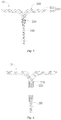
Fig. 4 is a schematic diagram of structure of an intervention guidance device according to an embodiment of the disclosure; -
FIG. 5 is a schematic diagram of the structure of the intervention guidance device shown inFIG. 4 from another perspective; -
FIG. 6 is an exploded view of the intervention guidance device shown inFIG. 4 ; -
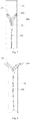
FIG. 7 is a schematic diagram of the structure of the intervention guidance device shown inFIG. 4 loaded into a delivery tube; -
FIG. 8 is a schematic diagram of the structure of the intervention guidance device shown inFIG. 4 released from the delivery tube; -
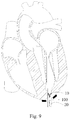
FIG. 9 is a schematic diagram of the structure of the intervention guidance device shown inFIG. 4 loaded into a delivery tube and placed into a ventricle; -
FIG. 10 is a schematic diagram of the structure of the intervention guidance device shown inFIG. 4 after a guidance portion is pushed out of the delivery tube; -
FIG. 11 is a schematic diagram of the structure of the intervention guidance device shown inFIG. 4 pushed in a left ventricle; -
FIG. 12 is a schematic diagram of the structure of the intervention guidance device shown inFIG. 4 after being pushed into a left atrium; -
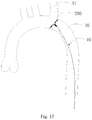
FIG. 13 is a schematic diagram of the structure of the intervention guidance device shown inFIG. 4 pushed in a blood vessel; -
FIG. 14 is a schematic diagram of the structure of the intervention guidance device shown inFIG. 4 at a branch blood vessel; -
FIG. 15 is a schematic diagram of the structure of an intervention guidance device loaded into a delivery tube in the prior art; -
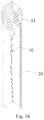
FIG. 16 is a schematic diagram of the structure of the intervention guidance device shown inFIG. 15 released from the delivery tube; -
FIG. 17 is a schematic diagram of the structure of the intervention guidance device shown inFIG. 15 after being released from the delivery tube; -
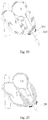
FIG. 18 is a schematic diagram of the structure of forming an apical pericardium on a heart; -
FIG. 19 is a schematic diagram of the structure of an apical puncture needle penetrating into the left ventricle; -
FIG. 20 is a schematic diagram of the structure of the delivery tube penetrating into the left ventricle; -
FIG. 21 is a schematic diagram of the structure of the intervention guidance device placed into the delivery tube; -
FIG. 22 is a schematic diagram of the structure of the intervention guidance device when being pushed into the left ventricle; -
FIG. 23 is a schematic diagram of the structure of the intervention guidance device after being pushed into the left atrium; -
FIG. 24 is a schematic diagram of the structure of an vitro-left ventricle-left atrium track established by the intervention guidance device; -
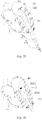
FIG. 25 is a schematic diagram of the structure of an apical dilated sheath and a sheath core penetrating into the left atrium; -
FIG. 26 is a schematic diagram of the structure of a valve delivery device inserted into the left atrium; -
FIG. 27 is a schematic diagram of the structure of a valve prosthesis partially released in the valve delivery device; -
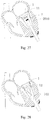
FIG. 28 is a schematic structure view of a valve body of the valve prosthesis after being released from the valve delivery device; -
FIG. 29 is a schematic diagram of the structure of the valve prosthesis after implantation. - In order that the above objects, features, and advantages of the disclosure can be more readily understood, specific implementations of the disclosure will be described below in detail with reference to the accompanying drawings. In the following description, numerous specific details are set forth in order to provide a thorough understanding of the disclosure. The disclosure may, however, be embodied in many different forms than those herein set forth, and such modifications as would occur to those skilled in the art may be made without departing from the spirit and scope of the disclosure.
- It will be understood that when an element is referred to as being "fixed" or "arranged" to another element, it may be directly on another element or an intermediate element may also be present. When an element is referred to as being "connected" to another element, it may be directly connected to another element or an intermediate element may be present at the same time. The terms "vertical", "horizontal", "left", "right" and the like as used herein are for illustrative purposes only and are not meant to be the only implementations.
- Unless defined otherwise, all technical and scientific terms used herein have the same meaning as commonly understood by those skilled in the art to which the disclosure belongs. The terms used in the description of the disclosure herein are for the purpose of describing specific implementations only and are not intended to be limiting of the disclosure. The term "and/or" as used herein includes any and all combinations of one or more of the associated listed items.
- It should be noted that in the field of intervention medical instruments, an end of a medical instrument implanted in a human or animal body that is closer to an operator is generally referred to as a "proximal end", an end that is further away from the operator is referred to as a "distal end", and the "proximal end" and "distal end" of any component of the medical instrument are defined in accordance with this principle. An "axial direction" generally refers to a longitudinal direction of the medical instrument when being delivered, and a "radial direction" generally refers to a direction of the medical instrument perpendicular to the "axial direction" thereof, and the "axial direction" and "radial direction" of any component of the medical instrument are defined in accordance with this principle.
- Referring to
FIG. 4 , anintervention guidance device 10 provided in the disclosure includes amain body portion 100 and aguidance portion 200. Theguidance device 200 is connected to a distal end of themain body portion 100. - The
guidance portion 200 has a contracted configuration used for delivery and a predetermined expanded configuration. Referring toFIG. 4 , in the expanded configuration, theguidance portion 200 has acentral area 201 and a closedouter edge 202 formed by the outward expansion of thecentral area 201, and the distal end of themain body portion 100 is connected to thecentral area 201. Referring toFIGS. 7 and 8 together, in the contracted configuration, for example in adelivery tube 20, theouter edge 202 is farther away from themain body portion 100 than thecentral area 201, that is, a maximum radial dimension position in the expanded configuration is in thedelivery tube 20 furthest from themain body portion 100. When themain body portion 100 is pushed causing theguidance portion 200 out of thedelivery tube 20, and when theouter edge 202 of theguidance portion 200 extends beyond the plane of a distal end of thedelivery tube 20, theguidance portion 200 is restorable from the contracted configuration to the expanded configuration. In the present embodiment, theguidance portion 200 is a planar body. Of course, in other embodiments, theguidance portion 200 is not necessarily limited to the planar body, and theguidance portion 200 may be in other configurations. As long as theouter edge 202 of theguidance portion 200 extends beyond the plane of the distal end of thedelivery device 20, theguidance portion 200 can be quickly restored from the contracted configuration to the expanded configuration. - It should be noted that when a distance by which the
outer edge 202 of theguidance portion 200 may extend beyond the plane of the distal end of thedelivery tube 20 is much less than a maximum radial dimension of theouter edge 202 of theguidance portion 200, for example, when the distance by which theouter edge 202 of theguidance portion 200 may extend beyond the plane of the distal end of thedelivery tube 20 is less than 1/2, 1/3, 1/4, 1/5, 1/6 or less of the maximum radial dimension of theouter edge 202 of theguidance portion 200, theguidance portion 200 can jump out of thedelivery tube 20 and can be restored from the contracted configuration to the expanded configuration. The radial dimension in the disclosure refers to the length of a connecting line of theouter edge 202 across a center point of thecentral area 201. For example, when theguidance portion 200 is disc-shaped, the radial dimension is a diameter. - In the illustrated embodiments, the
outer edge 202 of theguidance portion 200 is also further from the main body portion than thecentral area 201 in the expanded configuration. More specifically, the plane in which theouter edge 202 of theguidance portion 200 is located is a furthest end surface of theintervention guidance device 10. It will be appreciated that in other embodiments, theouter edge 202 of theguidance portion 200 may also be bent to a proximal end in the expanded configuration, that is, the plane in which the end of theouter edge 202 of theguidance portion 200 is located is not necessarily located in the furthest end surface of theintervention guidance device 10. - In the illustrated embodiments, the
central area 201 is recessed from the distal end to the proximal end so as to facilitate rapid restoration of theguidance portion 200 from the contracted configuration to the expanded configuration. In one embodiment, the recess extends to a position connected to themain body portion 100. - In one embodiment, referring to
FIG. 5 together, theguidance portion 200 includes a wovenmesh 210 woven by a plurality of mesh wires and aplug 220 used for gathering and fixing the mesh wires at the closing position of the wovenmesh 210, the mesh wires at the closing position located at a distal end of the wovenmesh 210 are fixed to theplug 220 after being bent from the distal end to a proximal end, and theguidance portion 200 is fixedly connected to the distal end of themain body portion 100 through theplug 220. The mesh wires may be superelastic metal or shape memory metal, such as nitinol. - It will be appreciated that in other embodiments, the
plug 220 may be omitted. For example, the mesh wires at the closing position may be gathered and fixed by welding or the like. - In the illustrated embodiments, the woven
mesh 210 includes a distal-end mesh surface 211 and a proximal-end mesh surface 213 which are integrally connected. The proximal-end mesh surface 213 is closer to themain body portion 100 than the distal-end mesh surface 211. The mesh wires at the closing position of the distal-end mesh surface 211 pass through the proximal-end mesh surface 213 and then are converged together with mesh wires at the closing position of the proximal-end mesh surface 213, and the converged mesh wires are gathered and fixed by theplug 220. Specifically, the wovenmesh 210 may be woven into a cylindrical tubular body by mesh wires. The mesh wires at the closing position of a distal end of the tubular body turn back to be converged with the mesh wires at the closing position of a proximal end and are closed and fixed by theplug 220 to form a planar body in which the distal-end mesh surface 211 and the proximal-end mesh surface 213 are attached to each other by heat-setting. In one embodiment, the wovenmesh 210 is woven from not less than 16 mesh wires, and each mesh wire has a wire diameter of 0.0028 inch to 0.0060 inch. In one embodiment, the wovenmesh 210 is woven from 36 to 72 mesh wires to maintain the radial deformability of the wovenmesh 210 and to increase an average mesh area of the wovenmesh 210. In the illustrated embodiments, the wovenmesh 210 is shaped into a planar disc-shaped structure having a diameter of 10 mm to 25 mm. Of course, in other embodiments, the wovenmesh 210 can also be shaped into other structures, such as a bowl-shaped structure recessed from the distal end to the proximal end. When the cross section of the wovenmesh 210 is not circular, the wovenmesh 210 has a radial dimension of 10 mm and 25 mm, that is, a straight line across the central area has a length of 10 mm and 25 mm. - Referring to
FIG. 6 , theplug 220 is provided with a threadedhole 221 for rotational connection with themain body portion 100. In the illustrated embodiments, theplug 220 is provided with internal threads, and themain body portion 100 is provided with external threads. In other embodiments, theplug 220 may also be provided with external threads, and themain body portion 100 is provided with internal threads. Of course, themain body portion 100 may also be fixedly connected to theplug 220 in other ways, such as welding. - The
plug 220 may be made of stainless steel or nitinol. Themain body portion 100 may be of a metallic or non-metallic structure. In one embodiment, themain body portion 100 is made of stainless steel or nitinol. Themain body portion 100 may have a solid structure. For example, themain body portion 100 may have a rod-like structure formed by a single wire or a cable structure formed by winding a plurality of wires. Themain body portion 100 may have a hollow structure. Themain body portion 100 may have an outer diameter of 1 mm and 3 mm. - Referring to
FIGS. 7 and 8 together, when themain body portion 100 passes through thedelivery tube 20 and is pulled from the proximal end, theguidance portion 200 may be deformed into thedelivery tube 20. At this moment, theouter edge 202 of theguidance portion 200 is located at the furthermost end, and thecentral area 201 is pulled to the proximal end. When themain body portion 100 is pushed distally, theguidance portion 200 may be quickly restored to the expanded configuration as the outer edge of theguidance portion 200 pushes out of thedelivery tube 20. - It will be appreciated that the
guidance portion 200 is not necessarily limited to a woven mesh structure. For example, theguidance portion 200 may also be a body planar structure formed by cutting. As long as theguidance portion 200 just extends out of the delivery tube, theguidance portion 200 may be instantly restored from the contracted configuration to the expanded configuration. - The
intervention guidance device 10 may be used as a guide wire for establishing an access track for a mitral valve prosthesis. Referring toFIGS. 9 and12 together, theintervention guidance device 10 is loaded into thedelivery tube 20, and thedelivery tube 20 enters a left ventricle from an apical position, the distal end of thedelivery tube 20 being at the bottom of the left ventricle. Themain body portion 100 is slowly pushed distally, and when the distal end of theguidance portion 200 is pushed out of thedelivery tube 20, theguidance portion 200 is quickly restored from the contracted configuration to the expanded configuration, and may adapt to the bottom of papillary muscles and conform to the shape of an inner wall of the heart. In the left ventricle, when themain body portion 100 is pushed distally, theguidance portion 200 may be attached to surrounding tissues andchordae tendineae 21. And the radial dimension of theguidance portion 200 is larger than agap 24 between thechordae tendineae 21, theguidance portion 200 does not enter the area between thechordae tendineae 21, and thechordae tendineae 21 pulled by thepapillary muscles 22 in the ventricle may be radially pushed away by theguidance portion 200. Themain body portion 100 is continuously pushed distally to amitral valve leaflet 23, and when the left ventricle relaxes, themitral valve leaflet 23 is in an opened state. Then themain body portion 100 is pushed, and theguidance portion 200 can enter a left atrium through themitral valve leaflet 23 to establish an vitro-left ventricle-left atrium access path. - In the above
intervention guidance device 10, by providing theguidance portion 200 with the radial dimension larger than the distance between the chordae tendineae, can establish an effective access path that does not cross the chordae tendineae, where the subsequent implantation of a heart valve prosthesis does not pass through the chordae tendineae. And the success rate of a heart valve prosthesis implantation surgery can be improved. - The
intervention guidance device 10 may also be used in a peripheral vascular surgery. In an aortic valve replacement surgery, theintervention guidance device 10 may be used as a guide wire to establish an access path for an aortic valve prosthesis. A general guide wire is often impacted by blood in the process of establishing an access, and a distal end of the guide wire is easily influenced by blood flow to enter a branch blood vessel of an aortic arch part, so that a lot of troubles are brought to the surgery. However, theintervention guidance device 10 of the present disclosure can better avoid this problem. Referring toFIGS. 13 to 14 , theintervention guidance device 10 enters a descendingaorta 30 through an arterial vessel of a lower limb. When theguidance portion 200 encounters abranch blood vessel 31, because the radial dimension of theguidance portion 200 is larger than an opening of thebranch blood vessel 31, theguidance portion 200 may avoid thebranch blood vessel 31 instead of entering thebranch blood vessel 31, thereby smoothly establishing an access path of an aortic valve prosthesis. In addition, theguidance portion 200 may also adapt to the shape of the inner wall of the blood vessel. The image can clearly show the shape of the blood vessel during the access process. - It should be noted that some guidance devices for ultrasound intervention are known in the prior art. Referring to
FIGS. 15 to 17 , an end of anintervention guidance device 40 is generally provided with a mesh-like three-dimensional structure 41 such as a sphere and an ellipsoid in order to be better shown under an ultrasound medium. After theintervention guidance device 40 is loaded into adelivery tube 20, a central area of the three-dimensional structure 41 may be located at two ends, and an outer edge may be located between the two ends. For example, the three-dimensional structure 41 will be contracted to a linear structure. When being pushed distally, the three-dimensional structure 41 needs to be pushed out for a certain distance, so that a distance of the three-dimensional structure 41 extending out of thedelivery tube 20 is not less than a distance of a maximum radial dimension of the three-dimensional structure 41. So the three-dimensional structure 41 can be restored from a contracted state to an expanded state. When theintervention guidance device 40 is applied to an implantation surgery of a valve prosthesis, since the three-dimensional structure 41 needs to be pushed out of thedelivery tube 41 for a long distance when the three-dimensional structure 41 is restored from the contracted state to the expanded state, the three-dimensional structure 41 may pass through some chordae tendineae at the bottom of a ventricle before the three-dimensional structure 41 is restored to the expanded state. Therefore, the established access path cannot be completely prevented from completely avoiding the chordae tendineae. In theintervention guidance device 10 of the disclosure, since a distance of theguidance portion 200 extending out of thedelivery tube 20 may be much less than the maximum radial dimension of the outer edge (the distance of extending is less than 1/2 of the maximum radial dimension of the outer edge, or the distance of extending may be ignored with respect to the maximum radial dimension of the outer edge), theguidance portion 200 can be instantly restored from the contracted configuration to the expanded configuration. Therefore, theguidance portion 200 can be completely prevented from penetrating into a gap of the chordae tendineae, thereby improving the success rate of a valve prosthesis implantation surgery. - In addition, the expanded state of the
guidance portion 200 has a large area, theguidance portion 20 may be detected by ultrasound and digital subtraction angiography (DSA) and has wide adaptability. Moreover, the position and shape of tissues are clearly determined by the shape of theguidance portion 200. - Referring to
FIGS. 18 to 29 , the disclosure also provides a method for implanting a valve prosthesis. The method includes the following steps: S11: an incision is formed in a left chest to expose a ventricle; S12: an access path is established from the ventricle to an atrium using anintervention guidance device 10 and avoids chordae tendineae; S13: avalve prosthesis 1 is placed along theintervention guidance device 10 at a native valve between the ventricle and the atrium through avalve delivery device 2. The method for implanting a valve prosthesis provided by the disclosure may effectively avoid the phenomenon of agap 24 between thechordae tendineae 21 in the process of establishing an access path of thevalve prosthesis 1, so that the phenomenon that atether 13 on thevalve prosthesis 2 passes through thegap 24 between thechordae tendineae 21 can be reduced in the implantation process of thevalve prosthesis 2. Therefore, the phenomenon that thevalve prosthesis 2 cannot be coaxially placed with the native valve since thetether 13 passes through thegap 24 between thechordae tendineae 21 in the implantation process of thevalve prosthesis 2 is reduced, and the phenomenon of perivalvular leakage after the implantation of thevalve prosthesis 2 is reduced. Meanwhile, the access path of the disclosure can effectively reduce the damage of thechordae tendineae 21 when thetether 13 of thevalve prosthesis 2 is hung on thechordae tendineae 21 during the implantation process. - For the convenience of describing the method for implanting an artificial heart valve of the disclosure, the disclosure is described by applying the method for implanting an artificial heart valve to an implantation surgery of the
mitral valve prosthesis 1. Referring toFIG. 18 , step S11 includes the following steps: - S111, an incision is made in an interval between fifth and sixth ribs of the left chest, and an apex of a left ventricle LV is exposed after opening a pericardium longitudinally through the incision;
- S112, an
apical pericardium 301 is sutured at the apex of the left ventricle LV; - When the surgery of the
valve prosthesis 2 is completed, tissues at an apical puncture may be pressed together by tightening theapical pericardium 301, which helps to improve the healing effect and the healing speed of the tissues at the apical puncture. - Referring to
FIGS. 19 to 24 , step S12 includes the following steps: - S121: Using the
apical puncture needle 310 to puncture the apex of the left ventricle LV at the position of theapical purse 301 to form a puncture hole; - S122, a
delivery tube 20 extends into the left ventricle LV through the puncture of theapical pericardium 301, and a positional relationship between thedelivery tube 20 and a ventricular wall is adjusted according to an image (for example, DSA image) such that a distal end of thedelivery tube 20 just enters the left ventricle LV or is exposed within 10 mm; - S123, the
intervention guidance device 10 is placed into a tube cavity of thedelivery tube 20, and with the aid of an image (for example, DSA image or ultrasound image), theintervention guidance device 10 is slowly pushed distally into the left ventricle LV so that an outer edge of aguidance portion 200 is just pushed out of the distal end of thedelivery tube 20 and is restored to an expanded configuration within the left ventricle LV. - S124, the
intervention guidance device 10 continues to be pushed until theguidance portion 200 is pushed into the left atrium LA. Specifically, the morphologic change of theguide portion 200 is observed with the aid of the image, if the distal end of theguidance portion 200 is bent to the proximal end, for example, as shown inFIG. 22 , the distal end of theguidance portion 200 is bent to the proximal end by thechordae tendineae 21. After that, theintervention guidance device 10 is withdrawn to the apex. And an angle of thedelivery tube 20 and a ventricular wall is adjusted, and theintervention guidance device 10 is slowly pushed toward the left atrium LA again. Theguidance portion 200 cannot be bent in the pushing process. If it is bent, theintervention guidance device 10 should be withdrawn. The step is repeated until theguidance portion 200 is pushed into the left atrium LA; - S125, the
delivery tube 20 is withdrawn, and theintervention guidance device 10 is reserved in the heart to obtain an vitro-left ventricle-left atrium track. - Referring to
FIGS. 25 to 29 , step S13 includes the following steps: - S131, an apical dilated
sheath 341 and asheath core 342 penetrate along themain body portion 100 into the left ventricle LV, and reach the left atrium LA across the mitral valve MV. The structure of the apical dilatedsheath 341 and thesheath core 342 may be referred to the prior art and will not be described in detail herein; - S132, the apical dilated
sheath 341 is fixed, thesheath core 342 and theintervention guidance device 10 are withdrawn from the heart, and thevalve delivery device 2 delivers thevalve prosthesis 1 to the mitral valve MV through the apical dilatedsheath 341;
Specifically, thevalve delivery device 2 is placed in the apical dilatedsheath 341, and thevalve delivery device 2 is slowly pushed, so that a distal end of anouter sheath 2010 of thevalve delivery device 2 passes through the mitral valve MV, and adevelopment ring 2011 of theouter sheath 2010 just crosses the mitral valve MV into the left atrium. Then the apical dilatedsheath 341 is withdrawn back into the left ventricle LV; - S133, the
valve prosthesis 1 is released from the valve delivery device, so that thevalve prosthesis 1 is located at the mitral valve MV. - Specifically, when the position of the
valve delivery device 2 is confirmed, a handle of thevalve delivery device 2 is rotated to withdraw theouter sheath 2010 proximally, so that avalve skirt 11 of thevalve prosthesis 1 is unconstrained on the left atrium LA while avalve stent body 12 is still within a cavity of thevalve delivery device 2. At this moment, the position of thevalve prosthesis 1 after being released on the left atrium LA is observed through a DSA image. If it is found that the release position of thevalve prosthesis 1 is inappropriate , theouter sheath 2010 is moved distally so that thevalve prosthesis 1 is recovered back into theouter sheath 2010. The above steps are repeated until it is confirmed that the release position of thevalve prosthesis 1 is correct, thevalve prosthesis 1 is completely released. Then thetether 13 at the proximal end of thevalve prosthesis 1 is pulled out of the left ventricle LV by thevalve delivery device 2. Thevalve delivery device 2 and the apical dilatedsheath 341 are withdrawn from the heart, thetether 13 is then tightened and fixed to an outer surface of the left ventricle LV, and theapical pericardium 301 at the apex of the left ventricle LV is finally tightened to complete the release of thevalve prosthesis 1. - It should be noted that the structure of the
valve delivery device 2 in the disclosure can be referred toCN201711479941.8 CN201711479996.9 CN201711487976.6 - The various technical features of the above-described embodiments may be combined in any combination, and in order to simplify the description, all possible combinations of the various technical features in the above-described embodiments are not described. However, as long as the combinations of these technical features do not contradict, they should be considered to be the scope of the description.
- The above-described examples express only a few implementations of the disclosure, which are described in greater detail but are not to be construed as limiting the scope of the disclosure. It will be appreciated by those of ordinary skill in the art that numerous variations and modifications may be made to the disclosure without departing from the concept of the disclosure, which fall within the protection scope of the disclosure. Therefore, the protection scope of the disclosure should be determined by the appended claims.
Claims (10)
- An intervention guidance device, comprising:a main body portion; anda guidance portion having a contracted configuration used for delivery and a predetermined expanded configuration, in the expanded configuration, the guidance portion has a central area and a closed outer edge formed by the outward expansion of the central area, and a distal end of the main body portion is connected to the central area; and in the contracted configuration, the outer edge is farther away from the main body portion than the central area, and when the outer edge of the guidance portion extends beyond a plane of a distal end of a delivery tube, the guidance portion is restorable from the contracted configuration to the expanded configuration.
- The intervention guidance device according to claim 1, wherein the guidance portion is a planar body.
- The intervention guidance device according to claim 1, wherein the guidance portion comprises a woven mesh woven by a plurality of mesh wires and a plug used for gathering and fixing the mesh wires at the closing position of the woven mesh, the plug is located in the central area, and the mesh wires at the closing position of the woven mesh located at a distal end of the woven mesh are fixed to the plug after being bent from the distal end to a proximal end.
- The intervention guidance device according to claim 3, wherein the woven mesh comprises a distal-end mesh surface and a proximal-end mesh surface which are integrally connected, the proximal-end mesh surface is closer to the main body portion than the distal-end mesh surface, the mesh wires at the closing position of the distal-end mesh surface pass through the proximal-end mesh surface and then are converged together with the mesh wires at the closing position of the proximal-end mesh surface, and the converged mesh wires are gathered and fixed by the plug.
- The intervention guidance device according to claim 3 or 4, wherein the woven mesh is woven from not less than 16 mesh wires, and a wire diameter of each mesh wire is in a range from 0.0028 inch to 0.0060 inch.
- The intervention guidance device according to claim 3 or 4, wherein the plug is provided with threads for rotational connection with the main body portion.
- An intervention guidance device, comprising:a main body portion; anda guidance portion having a contracted configuration used for delivery and a predetermined expanded configuration, and the guidance portion comprises a woven mesh woven from a plurality of mesh wires and a plug used for gathering and fixing the mesh wires at the closing position of the woven mesh, the mesh wires at the closing position of the woven mesh located at a distal end of the woven mesh are fixed to the plug after being bent from the distal end to a proximal end, and the guidance portion is fixedly connected to a distal end of the main body portion through the plug.
- The intervention guidance device according to claim 7, wherein the woven mesh comprises a distal-end mesh surface and a proximal-end mesh surface which are integrally connected, the proximal-end mesh surface is closer to the main body portion than the distal-end mesh surface, the mesh wires at the closing position of the distal-end mesh surface pass through the proximal-end mesh surface and then are converged together with the mesh wires at the closing position of the proximal-end mesh surface, and the converged mesh wires are gathered and fixed by the plug.
- The intervention guidance device according to claim 7 or 8, wherein the woven mesh is woven from not less than 16 mesh wires, and each mesh wire has a wire diameter of 0.0028 inch to 0.0060 inch.
- The intervention guidance device according to claim 7 or 8, wherein the plug is provided with threads for rotational connection with the main body portion.
Applications Claiming Priority (2)
| Application Number | Priority Date | Filing Date | Title |
|---|---|---|---|
| CN201811615406.5A CN111374798B (en) | 2018-12-27 | 2018-12-27 | Interventional guiding device |
| PCT/CN2019/095419 WO2020134025A1 (en) | 2018-12-27 | 2019-07-10 | Intervention guidance device |
Publications (3)
| Publication Number | Publication Date |
|---|---|
| EP3903736A1 true EP3903736A1 (en) | 2021-11-03 |
| EP3903736A4 EP3903736A4 (en) | 2022-10-12 |
| EP3903736B1 EP3903736B1 (en) | 2025-11-12 |
Family
ID=71127544
Family Applications (1)
| Application Number | Title | Priority Date | Filing Date |
|---|---|---|---|
| EP19905159.0A Active EP3903736B1 (en) | 2018-12-27 | 2019-07-10 | Intervention guidance device |
Country Status (4)
| Country | Link |
|---|---|
| US (1) | US11771556B2 (en) |
| EP (1) | EP3903736B1 (en) |
| CN (1) | CN111374798B (en) |
| WO (1) | WO2020134025A1 (en) |
Families Citing this family (4)
| Publication number | Priority date | Publication date | Assignee | Title |
|---|---|---|---|---|
| CN109069272A (en) * | 2016-04-29 | 2018-12-21 | 美敦力瓦斯科尔勒公司 | Prosthetic heart valve device with tethered anchor and associated systems and methods |
| CN111904663A (en) * | 2020-08-18 | 2020-11-10 | 上海竑宇医疗科技有限公司 | Ring retractor and mounting method thereof |
| CN114504352A (en) * | 2022-03-09 | 2022-05-17 | 山东省千佛山医院 | Ventricular septum is perforated isolated with heart plug device and system |
| CN116458926B (en) * | 2023-03-27 | 2026-02-13 | 上海翰凌医疗器械有限公司 | An ultrasonic directional guidance device |
Family Cites Families (25)
| Publication number | Priority date | Publication date | Assignee | Title |
|---|---|---|---|---|
| US6142993A (en) * | 1998-02-27 | 2000-11-07 | Ep Technologies, Inc. | Collapsible spline structure using a balloon as an expanding actuator |
| CN101415379B (en) * | 2006-02-14 | 2012-06-20 | 萨德拉医学公司 | Systems for delivering medical implants |
| CN101662999B (en) * | 2006-09-28 | 2016-01-20 | 心叶科技公司 | Delivery tools for percutaneous delivery of prostheses |
| US9149610B2 (en) * | 2007-05-31 | 2015-10-06 | Abbott Cardiovascular Systems Inc. | Method and apparatus for improving delivery of an agent to a kidney |
| US20090264859A1 (en) | 2008-04-21 | 2009-10-22 | Medtronic Vascular, Inc. | Catheter Having a Selectively Expandable Distal Tip |
| CN108283534B (en) * | 2012-01-31 | 2019-09-24 | 米特拉尔维尔福科技有限责任公司 | Bicuspid valve parking device and system |
| US20130226278A1 (en) * | 2012-02-23 | 2013-08-29 | Tyco Healthcare Group Lp | Methods and apparatus for luminal stenting |
| JP6545103B2 (en) * | 2013-01-25 | 2019-07-17 | メドテンシア インターナショナル エルティーディー オーワイ | Heart valve repair system |
| US9232998B2 (en) * | 2013-03-15 | 2016-01-12 | Cardiosolutions Inc. | Trans-apical implant systems, implants and methods |
| US20160022291A1 (en) * | 2013-03-15 | 2016-01-28 | Volcano Corporation | Retrieval and centering device and method with pressure and ultrasound features |
| CN105682611B (en) | 2013-10-28 | 2018-06-01 | 坦迪尼控股股份有限公司 | Prosthetic heart valve and systems and methods for delivering a prosthetic heart valve |
| EP3128962B1 (en) * | 2014-04-08 | 2018-05-23 | Stryker Corporation | Implant delivery system |
| US10524792B2 (en) * | 2014-12-04 | 2020-01-07 | Edwards Lifesciences Corporation | Percutaneous clip for repairing a heart valve |
| WO2016100334A1 (en) | 2014-12-19 | 2016-06-23 | Heartware, Inc. | Guidewire system and method of pump installation using same |
| EP3349689B1 (en) * | 2015-09-18 | 2023-12-27 | Microvention, Inc. | Implant retention, detachment, and delivery system |
| WO2017079153A1 (en) * | 2015-11-02 | 2017-05-11 | University Of Maryland, Baltimore | Distal anchor apparatus and methods for mitral valve repair |
| US10470876B2 (en) * | 2015-11-10 | 2019-11-12 | Edwards Lifesciences Corporation | Transcatheter heart valve for replacing natural mitral valve |
| US10258491B2 (en) * | 2016-02-02 | 2019-04-16 | Inspiremd, Ltd. | Deformable tip for stent delivery and methods of use |
| CN109069272A (en) * | 2016-04-29 | 2018-12-21 | 美敦力瓦斯科尔勒公司 | Prosthetic heart valve device with tethered anchor and associated systems and methods |
| US10470877B2 (en) | 2016-05-03 | 2019-11-12 | Tendyne Holdings, Inc. | Apparatus and methods for anterior valve leaflet management |
| EP3482145B1 (en) | 2016-07-06 | 2023-06-14 | Whirlpool Corporation | Refrigeration appliance comprising a refrigerated compartment air distribution assembly |
| CN108056798B (en) * | 2016-11-08 | 2021-06-04 | 艾柯医疗器械(北京)有限公司 | Support pushing system, corresponding blood flow guiding device and blood flow guiding device assembling method |
| US10493248B2 (en) * | 2016-11-09 | 2019-12-03 | Medtronic Vascular, Inc. | Chordae tendineae management devices for use with a valve prosthesis delivery system and methods of use thereof |
| US10368988B2 (en) * | 2016-11-09 | 2019-08-06 | Medtronic Vascular, Inc. | Valve delivery system having an integral displacement component for managing chordae tendineae in situ and methods of use thereof |
| CN108904102B (en) * | 2018-07-19 | 2023-12-12 | 上海诺强医疗科技有限公司 | Transcatheter mitral valve systole system and method of use thereof |
-
2018
- 2018-12-27 CN CN201811615406.5A patent/CN111374798B/en active Active
-
2019
- 2019-07-10 WO PCT/CN2019/095419 patent/WO2020134025A1/en not_active Ceased
- 2019-07-10 EP EP19905159.0A patent/EP3903736B1/en active Active
- 2019-07-10 US US17/418,618 patent/US11771556B2/en active Active
Also Published As
| Publication number | Publication date |
|---|---|
| CN111374798B (en) | 2021-12-03 |
| EP3903736B1 (en) | 2025-11-12 |
| US20220079751A1 (en) | 2022-03-17 |
| EP3903736A4 (en) | 2022-10-12 |
| WO2020134025A1 (en) | 2020-07-02 |
| US11771556B2 (en) | 2023-10-03 |
| CN111374798A (en) | 2020-07-07 |
Similar Documents
| Publication | Publication Date | Title |
|---|---|---|
| US20240180703A1 (en) | Transcatheter artificial cusp for valve insufficiency | |
| JP6479043B2 (en) | Heart valve fixation device | |
| US11771556B2 (en) | Intervention guidance device | |
| US12569341B2 (en) | Device for arranging guidewires around a heart valve | |
| US20250025301A1 (en) | Transcatheter artificial cusp for valve insufficiency | |
| US11135053B2 (en) | Implantation method of artificial heart valve | |
| WO2010080107A1 (en) | Cardiovascular valve and valve housing apparatuses and systems | |
| US12059345B2 (en) | Transcatheter prosthetic valve replacement system | |
| EP4003229B1 (en) | Device for implanting a prosthesis for a heart valve | |
| US12485003B2 (en) | Device for implanting a prosthesis for a heart valve and assembly procedure | |
| EP4233973B1 (en) | Device for arranging guide wires around a heart valve | |
| HK40042111A (en) | Transcatheter artificial cusp for valve insufficiency |
Legal Events
| Date | Code | Title | Description |
|---|---|---|---|
| STAA | Information on the status of an ep patent application or granted ep patent |
Free format text: STATUS: THE INTERNATIONAL PUBLICATION HAS BEEN MADE |
|
| PUAI | Public reference made under article 153(3) epc to a published international application that has entered the european phase |
Free format text: ORIGINAL CODE: 0009012 |
|
| STAA | Information on the status of an ep patent application or granted ep patent |
Free format text: STATUS: REQUEST FOR EXAMINATION WAS MADE |
|
| 17P | Request for examination filed |
Effective date: 20210726 |
|
| AK | Designated contracting states |
Kind code of ref document: A1 Designated state(s): AL AT BE BG CH CY CZ DE DK EE ES FI FR GB GR HR HU IE IS IT LI LT LU LV MC MK MT NL NO PL PT RO RS SE SI SK SM TR |
|
| DAV | Request for validation of the european patent (deleted) | ||
| DAX | Request for extension of the european patent (deleted) | ||
| A4 | Supplementary search report drawn up and despatched |
Effective date: 20220912 |
|
| RIC1 | Information provided on ipc code assigned before grant |
Ipc: A61B 17/00 20060101ALN20220906BHEP Ipc: A61M 25/00 20060101ALI20220906BHEP Ipc: A61B 17/02 20060101ALI20220906BHEP Ipc: A61M 25/09 20060101ALI20220906BHEP Ipc: A61F 2/24 20060101AFI20220906BHEP |
|
| RAP1 | Party data changed (applicant data changed or rights of an application transferred) |
Owner name: SHENZHEN LIFEVALVE MEDICAL SCIENTIFIC CO., LTD. |
|
| GRAP | Despatch of communication of intention to grant a patent |
Free format text: ORIGINAL CODE: EPIDOSNIGR1 |
|
| STAA | Information on the status of an ep patent application or granted ep patent |
Free format text: STATUS: GRANT OF PATENT IS INTENDED |
|
| RIC1 | Information provided on ipc code assigned before grant |
Ipc: A61B 17/00 20060101ALN20250604BHEP Ipc: A61M 25/00 20060101ALI20250604BHEP Ipc: A61B 17/02 20060101ALI20250604BHEP Ipc: A61M 25/09 20060101ALI20250604BHEP Ipc: A61F 2/24 20060101AFI20250604BHEP |
|
| INTG | Intention to grant announced |
Effective date: 20250617 |
|
| GRAS | Grant fee paid |
Free format text: ORIGINAL CODE: EPIDOSNIGR3 |
|
| GRAA | (expected) grant |
Free format text: ORIGINAL CODE: 0009210 |
|
| STAA | Information on the status of an ep patent application or granted ep patent |
Free format text: STATUS: THE PATENT HAS BEEN GRANTED |
|
| P01 | Opt-out of the competence of the unified patent court (upc) registered |
Free format text: CASE NUMBER: UPC_APP_5984_3903736/2025 Effective date: 20250904 |
|
| AK | Designated contracting states |
Kind code of ref document: B1 Designated state(s): AL AT BE BG CH CY CZ DE DK EE ES FI FR GB GR HR HU IE IS IT LI LT LU LV MC MK MT NL NO PL PT RO RS SE SI SK SM TR |
|
| REG | Reference to a national code |
Ref country code: CH Ref legal event code: F10 Free format text: ST27 STATUS EVENT CODE: U-0-0-F10-F00 (AS PROVIDED BY THE NATIONAL OFFICE) Effective date: 20251112 Ref country code: GB Ref legal event code: FG4D |
|
| REG | Reference to a national code |
Ref country code: IE Ref legal event code: FG4D |
|
| REG | Reference to a national code |
Ref country code: DE Ref legal event code: R096 Ref document number: 602019078140 Country of ref document: DE |
|
| REG | Reference to a national code |
Ref country code: NL Ref legal event code: MP Effective date: 20251112 |
|
| PG25 | Lapsed in a contracting state [announced via postgrant information from national office to epo] |
Ref country code: ES Free format text: LAPSE BECAUSE OF FAILURE TO SUBMIT A TRANSLATION OF THE DESCRIPTION OR TO PAY THE FEE WITHIN THE PRESCRIBED TIME-LIMIT Effective date: 20251112 |
|
| REG | Reference to a national code |
Ref country code: LT Ref legal event code: MG9D |
|
| PG25 | Lapsed in a contracting state [announced via postgrant information from national office to epo] |
Ref country code: NO Free format text: LAPSE BECAUSE OF FAILURE TO SUBMIT A TRANSLATION OF THE DESCRIPTION OR TO PAY THE FEE WITHIN THE PRESCRIBED TIME-LIMIT Effective date: 20260212 |
|
| PG25 | Lapsed in a contracting state [announced via postgrant information from national office to epo] |
Ref country code: HR Free format text: LAPSE BECAUSE OF FAILURE TO SUBMIT A TRANSLATION OF THE DESCRIPTION OR TO PAY THE FEE WITHIN THE PRESCRIBED TIME-LIMIT Effective date: 20251112 Ref country code: FI Free format text: LAPSE BECAUSE OF FAILURE TO SUBMIT A TRANSLATION OF THE DESCRIPTION OR TO PAY THE FEE WITHIN THE PRESCRIBED TIME-LIMIT Effective date: 20251112 Ref country code: AT Free format text: LAPSE BECAUSE OF FAILURE TO SUBMIT A TRANSLATION OF THE DESCRIPTION OR TO PAY THE FEE WITHIN THE PRESCRIBED TIME-LIMIT Effective date: 20251112 |
|
| REG | Reference to a national code |
Ref country code: AT Ref legal event code: MK05 Ref document number: 1856121 Country of ref document: AT Kind code of ref document: T Effective date: 20251112 |
|
| PG25 | Lapsed in a contracting state [announced via postgrant information from national office to epo] |
Ref country code: NL Free format text: LAPSE BECAUSE OF FAILURE TO SUBMIT A TRANSLATION OF THE DESCRIPTION OR TO PAY THE FEE WITHIN THE PRESCRIBED TIME-LIMIT Effective date: 20251112 |
|
| PG25 | Lapsed in a contracting state [announced via postgrant information from national office to epo] |
Ref country code: RS Free format text: LAPSE BECAUSE OF FAILURE TO SUBMIT A TRANSLATION OF THE DESCRIPTION OR TO PAY THE FEE WITHIN THE PRESCRIBED TIME-LIMIT Effective date: 20260212 |
|
| PG25 | Lapsed in a contracting state [announced via postgrant information from national office to epo] |
Ref country code: IS Free format text: LAPSE BECAUSE OF FAILURE TO SUBMIT A TRANSLATION OF THE DESCRIPTION OR TO PAY THE FEE WITHIN THE PRESCRIBED TIME-LIMIT Effective date: 20260312 |
|
| PG25 | Lapsed in a contracting state [announced via postgrant information from national office to epo] |
Ref country code: PT Free format text: LAPSE BECAUSE OF FAILURE TO SUBMIT A TRANSLATION OF THE DESCRIPTION OR TO PAY THE FEE WITHIN THE PRESCRIBED TIME-LIMIT Effective date: 20260312 |
|
| PG25 | Lapsed in a contracting state [announced via postgrant information from national office to epo] |
Ref country code: PL Free format text: LAPSE BECAUSE OF FAILURE TO SUBMIT A TRANSLATION OF THE DESCRIPTION OR TO PAY THE FEE WITHIN THE PRESCRIBED TIME-LIMIT Effective date: 20251112 |
|
| PG25 | Lapsed in a contracting state [announced via postgrant information from national office to epo] |
Ref country code: LV Free format text: LAPSE BECAUSE OF FAILURE TO SUBMIT A TRANSLATION OF THE DESCRIPTION OR TO PAY THE FEE WITHIN THE PRESCRIBED TIME-LIMIT Effective date: 20251112 |
|
| PG25 | Lapsed in a contracting state [announced via postgrant information from national office to epo] |
Ref country code: BG Free format text: LAPSE BECAUSE OF FAILURE TO SUBMIT A TRANSLATION OF THE DESCRIPTION OR TO PAY THE FEE WITHIN THE PRESCRIBED TIME-LIMIT Effective date: 20251112 |