EP3903729A1 - Vascular stent - Google Patents
Vascular stent Download PDFInfo
- Publication number
- EP3903729A1 EP3903729A1 EP19903169.1A EP19903169A EP3903729A1 EP 3903729 A1 EP3903729 A1 EP 3903729A1 EP 19903169 A EP19903169 A EP 19903169A EP 3903729 A1 EP3903729 A1 EP 3903729A1
- Authority
- EP
- European Patent Office
- Prior art keywords
- stent
- support
- vascular stent
- tube
- distal
- Prior art date
- Legal status (The legal status is an assumption and is not a legal conclusion. Google has not performed a legal analysis and makes no representation as to the accuracy of the status listed.)
- Granted
Links
Images



Classifications
-
- A—HUMAN NECESSITIES
- A61—MEDICAL OR VETERINARY SCIENCE; HYGIENE
- A61F—FILTERS IMPLANTABLE INTO BLOOD VESSELS; PROSTHESES; DEVICES PROVIDING PATENCY TO, OR PREVENTING COLLAPSING OF, TUBULAR STRUCTURES OF THE BODY, e.g. STENTS; ORTHOPAEDIC, NURSING OR CONTRACEPTIVE DEVICES; FOMENTATION; TREATMENT OR PROTECTION OF EYES OR EARS; BANDAGES, DRESSINGS OR ABSORBENT PADS; FIRST-AID KITS
- A61F2/00—Filters implantable into blood vessels; Prostheses, i.e. artificial substitutes or replacements for parts of the body; Appliances for connecting them with the body; Devices providing patency to, or preventing collapsing of, tubular structures of the body, e.g. stents
- A61F2/82—Devices providing patency to, or preventing collapsing of, tubular structures of the body, e.g. stents
- A61F2/848—Devices providing patency to, or preventing collapsing of, tubular structures of the body, e.g. stents having means for fixation to the vessel wall, e.g. barbs
-
- A—HUMAN NECESSITIES
- A61—MEDICAL OR VETERINARY SCIENCE; HYGIENE
- A61F—FILTERS IMPLANTABLE INTO BLOOD VESSELS; PROSTHESES; DEVICES PROVIDING PATENCY TO, OR PREVENTING COLLAPSING OF, TUBULAR STRUCTURES OF THE BODY, e.g. STENTS; ORTHOPAEDIC, NURSING OR CONTRACEPTIVE DEVICES; FOMENTATION; TREATMENT OR PROTECTION OF EYES OR EARS; BANDAGES, DRESSINGS OR ABSORBENT PADS; FIRST-AID KITS
- A61F2/00—Filters implantable into blood vessels; Prostheses, i.e. artificial substitutes or replacements for parts of the body; Appliances for connecting them with the body; Devices providing patency to, or preventing collapsing of, tubular structures of the body, e.g. stents
- A61F2/82—Devices providing patency to, or preventing collapsing of, tubular structures of the body, e.g. stents
- A61F2/86—Stents in a form characterised by the wire-like elements; Stents in the form characterised by a net-like or mesh-like structure
- A61F2/90—Stents in a form characterised by the wire-like elements; Stents in the form characterised by a net-like or mesh-like structure characterised by a net-like or mesh-like structure
-
- A—HUMAN NECESSITIES
- A61—MEDICAL OR VETERINARY SCIENCE; HYGIENE
- A61F—FILTERS IMPLANTABLE INTO BLOOD VESSELS; PROSTHESES; DEVICES PROVIDING PATENCY TO, OR PREVENTING COLLAPSING OF, TUBULAR STRUCTURES OF THE BODY, e.g. STENTS; ORTHOPAEDIC, NURSING OR CONTRACEPTIVE DEVICES; FOMENTATION; TREATMENT OR PROTECTION OF EYES OR EARS; BANDAGES, DRESSINGS OR ABSORBENT PADS; FIRST-AID KITS
- A61F2/00—Filters implantable into blood vessels; Prostheses, i.e. artificial substitutes or replacements for parts of the body; Appliances for connecting them with the body; Devices providing patency to, or preventing collapsing of, tubular structures of the body, e.g. stents
- A61F2/82—Devices providing patency to, or preventing collapsing of, tubular structures of the body, e.g. stents
- A61F2/844—Devices providing patency to, or preventing collapsing of, tubular structures of the body, e.g. stents folded prior to deployment
-
- A—HUMAN NECESSITIES
- A61—MEDICAL OR VETERINARY SCIENCE; HYGIENE
- A61F—FILTERS IMPLANTABLE INTO BLOOD VESSELS; PROSTHESES; DEVICES PROVIDING PATENCY TO, OR PREVENTING COLLAPSING OF, TUBULAR STRUCTURES OF THE BODY, e.g. STENTS; ORTHOPAEDIC, NURSING OR CONTRACEPTIVE DEVICES; FOMENTATION; TREATMENT OR PROTECTION OF EYES OR EARS; BANDAGES, DRESSINGS OR ABSORBENT PADS; FIRST-AID KITS
- A61F2/00—Filters implantable into blood vessels; Prostheses, i.e. artificial substitutes or replacements for parts of the body; Appliances for connecting them with the body; Devices providing patency to, or preventing collapsing of, tubular structures of the body, e.g. stents
- A61F2/82—Devices providing patency to, or preventing collapsing of, tubular structures of the body, e.g. stents
- A61F2/856—Single tubular stent with a side portal passage
-
- A—HUMAN NECESSITIES
- A61—MEDICAL OR VETERINARY SCIENCE; HYGIENE
- A61F—FILTERS IMPLANTABLE INTO BLOOD VESSELS; PROSTHESES; DEVICES PROVIDING PATENCY TO, OR PREVENTING COLLAPSING OF, TUBULAR STRUCTURES OF THE BODY, e.g. STENTS; ORTHOPAEDIC, NURSING OR CONTRACEPTIVE DEVICES; FOMENTATION; TREATMENT OR PROTECTION OF EYES OR EARS; BANDAGES, DRESSINGS OR ABSORBENT PADS; FIRST-AID KITS
- A61F2/00—Filters implantable into blood vessels; Prostheses, i.e. artificial substitutes or replacements for parts of the body; Appliances for connecting them with the body; Devices providing patency to, or preventing collapsing of, tubular structures of the body, e.g. stents
- A61F2/82—Devices providing patency to, or preventing collapsing of, tubular structures of the body, e.g. stents
- A61F2/852—Two or more distinct overlapping stents
-
- A—HUMAN NECESSITIES
- A61—MEDICAL OR VETERINARY SCIENCE; HYGIENE
- A61F—FILTERS IMPLANTABLE INTO BLOOD VESSELS; PROSTHESES; DEVICES PROVIDING PATENCY TO, OR PREVENTING COLLAPSING OF, TUBULAR STRUCTURES OF THE BODY, e.g. STENTS; ORTHOPAEDIC, NURSING OR CONTRACEPTIVE DEVICES; FOMENTATION; TREATMENT OR PROTECTION OF EYES OR EARS; BANDAGES, DRESSINGS OR ABSORBENT PADS; FIRST-AID KITS
- A61F2/00—Filters implantable into blood vessels; Prostheses, i.e. artificial substitutes or replacements for parts of the body; Appliances for connecting them with the body; Devices providing patency to, or preventing collapsing of, tubular structures of the body, e.g. stents
- A61F2/82—Devices providing patency to, or preventing collapsing of, tubular structures of the body, e.g. stents
- A61F2002/821—Ostial stents
-
- A—HUMAN NECESSITIES
- A61—MEDICAL OR VETERINARY SCIENCE; HYGIENE
- A61F—FILTERS IMPLANTABLE INTO BLOOD VESSELS; PROSTHESES; DEVICES PROVIDING PATENCY TO, OR PREVENTING COLLAPSING OF, TUBULAR STRUCTURES OF THE BODY, e.g. STENTS; ORTHOPAEDIC, NURSING OR CONTRACEPTIVE DEVICES; FOMENTATION; TREATMENT OR PROTECTION OF EYES OR EARS; BANDAGES, DRESSINGS OR ABSORBENT PADS; FIRST-AID KITS
- A61F2/00—Filters implantable into blood vessels; Prostheses, i.e. artificial substitutes or replacements for parts of the body; Appliances for connecting them with the body; Devices providing patency to, or preventing collapsing of, tubular structures of the body, e.g. stents
- A61F2/82—Devices providing patency to, or preventing collapsing of, tubular structures of the body, e.g. stents
- A61F2002/828—Means for connecting a plurality of stents allowing flexibility of the whole structure
-
- A—HUMAN NECESSITIES
- A61—MEDICAL OR VETERINARY SCIENCE; HYGIENE
- A61F—FILTERS IMPLANTABLE INTO BLOOD VESSELS; PROSTHESES; DEVICES PROVIDING PATENCY TO, OR PREVENTING COLLAPSING OF, TUBULAR STRUCTURES OF THE BODY, e.g. STENTS; ORTHOPAEDIC, NURSING OR CONTRACEPTIVE DEVICES; FOMENTATION; TREATMENT OR PROTECTION OF EYES OR EARS; BANDAGES, DRESSINGS OR ABSORBENT PADS; FIRST-AID KITS
- A61F2210/00—Particular material properties of prostheses classified in groups A61F2/00 - A61F2/26 or A61F2/82 or A61F9/00 or A61F11/00 or subgroups thereof
- A61F2210/0076—Particular material properties of prostheses classified in groups A61F2/00 - A61F2/26 or A61F2/82 or A61F9/00 or A61F11/00 or subgroups thereof multilayered, e.g. laminated structures
-
- A—HUMAN NECESSITIES
- A61—MEDICAL OR VETERINARY SCIENCE; HYGIENE
- A61F—FILTERS IMPLANTABLE INTO BLOOD VESSELS; PROSTHESES; DEVICES PROVIDING PATENCY TO, OR PREVENTING COLLAPSING OF, TUBULAR STRUCTURES OF THE BODY, e.g. STENTS; ORTHOPAEDIC, NURSING OR CONTRACEPTIVE DEVICES; FOMENTATION; TREATMENT OR PROTECTION OF EYES OR EARS; BANDAGES, DRESSINGS OR ABSORBENT PADS; FIRST-AID KITS
- A61F2220/00—Fixations or connections for prostheses classified in groups A61F2/00 - A61F2/26 or A61F2/82 or A61F9/00 or A61F11/00 or subgroups thereof
- A61F2220/0025—Connections or couplings between prosthetic parts, e.g. between modular parts; Connecting elements
-
- A—HUMAN NECESSITIES
- A61—MEDICAL OR VETERINARY SCIENCE; HYGIENE
- A61F—FILTERS IMPLANTABLE INTO BLOOD VESSELS; PROSTHESES; DEVICES PROVIDING PATENCY TO, OR PREVENTING COLLAPSING OF, TUBULAR STRUCTURES OF THE BODY, e.g. STENTS; ORTHOPAEDIC, NURSING OR CONTRACEPTIVE DEVICES; FOMENTATION; TREATMENT OR PROTECTION OF EYES OR EARS; BANDAGES, DRESSINGS OR ABSORBENT PADS; FIRST-AID KITS
- A61F2230/00—Geometry of prostheses classified in groups A61F2/00 - A61F2/26 or A61F2/82 or A61F9/00 or A61F11/00 or subgroups thereof
- A61F2230/0002—Two-dimensional shapes, e.g. cross-sections
- A61F2230/0028—Shapes in the form of latin or greek characters
- A61F2230/005—Rosette-shaped, e.g. star-shaped
-
- A—HUMAN NECESSITIES
- A61—MEDICAL OR VETERINARY SCIENCE; HYGIENE
- A61F—FILTERS IMPLANTABLE INTO BLOOD VESSELS; PROSTHESES; DEVICES PROVIDING PATENCY TO, OR PREVENTING COLLAPSING OF, TUBULAR STRUCTURES OF THE BODY, e.g. STENTS; ORTHOPAEDIC, NURSING OR CONTRACEPTIVE DEVICES; FOMENTATION; TREATMENT OR PROTECTION OF EYES OR EARS; BANDAGES, DRESSINGS OR ABSORBENT PADS; FIRST-AID KITS
- A61F2230/00—Geometry of prostheses classified in groups A61F2/00 - A61F2/26 or A61F2/82 or A61F9/00 or A61F11/00 or subgroups thereof
- A61F2230/0002—Two-dimensional shapes, e.g. cross-sections
- A61F2230/0028—Shapes in the form of latin or greek characters
- A61F2230/0052—T-shaped
-
- A—HUMAN NECESSITIES
- A61—MEDICAL OR VETERINARY SCIENCE; HYGIENE
- A61F—FILTERS IMPLANTABLE INTO BLOOD VESSELS; PROSTHESES; DEVICES PROVIDING PATENCY TO, OR PREVENTING COLLAPSING OF, TUBULAR STRUCTURES OF THE BODY, e.g. STENTS; ORTHOPAEDIC, NURSING OR CONTRACEPTIVE DEVICES; FOMENTATION; TREATMENT OR PROTECTION OF EYES OR EARS; BANDAGES, DRESSINGS OR ABSORBENT PADS; FIRST-AID KITS
- A61F2250/00—Special features of prostheses classified in groups A61F2/00 - A61F2/26 or A61F2/82 or A61F9/00 or A61F11/00 or subgroups thereof
- A61F2250/0014—Special features of prostheses classified in groups A61F2/00 - A61F2/26 or A61F2/82 or A61F9/00 or A61F11/00 or subgroups thereof having different values of a given property or geometrical feature, e.g. mechanical property or material property, at different locations within the same prosthesis
- A61F2250/0039—Special features of prostheses classified in groups A61F2/00 - A61F2/26 or A61F2/82 or A61F9/00 or A61F11/00 or subgroups thereof having different values of a given property or geometrical feature, e.g. mechanical property or material property, at different locations within the same prosthesis differing in diameter
-
- A—HUMAN NECESSITIES
- A61—MEDICAL OR VETERINARY SCIENCE; HYGIENE
- A61F—FILTERS IMPLANTABLE INTO BLOOD VESSELS; PROSTHESES; DEVICES PROVIDING PATENCY TO, OR PREVENTING COLLAPSING OF, TUBULAR STRUCTURES OF THE BODY, e.g. STENTS; ORTHOPAEDIC, NURSING OR CONTRACEPTIVE DEVICES; FOMENTATION; TREATMENT OR PROTECTION OF EYES OR EARS; BANDAGES, DRESSINGS OR ABSORBENT PADS; FIRST-AID KITS
- A61F2250/00—Special features of prostheses classified in groups A61F2/00 - A61F2/26 or A61F2/82 or A61F9/00 or A61F11/00 or subgroups thereof
- A61F2250/0058—Additional features; Implant or prostheses properties not otherwise provided for
- A61F2250/006—Additional features; Implant or prostheses properties not otherwise provided for modular
Definitions
- the disclosure relates to the technical field of interventional medical devices, in particular to a vascular stent.
- the branch vessel opened by the in-situ fenestration techniques tends to form thrombus due to the shape of the fenestra in a main stent tube 20' and the swinging of a film at the fenestration site after the fenestration under the flushing of blood, and even the phenomenon of re-blocking the blood flow in the branch vessel can occur. Therefore, after the main stent tube 20' is fenestrated in situ, a branch stent tube 10' is generally implanted into the fenestration site of the main stent tube 20' to fix the fenestration site and ensure the normal blood supply of the branch vessel. However, as shown in FIGS.
- the mechanical properties of the branch stent tube 10' itself may also present some safety hazards: as an aortic arch pulsates, the branch stent tube 10' tends to move, and even when an anchoring force of the branch stent tube 10' is weak, the branch stent tube 10' may become dislodged and fall into a distal end of the branch vessel or into an aorta (the direction indicated by an arrow in FIGS. 2 and 3 is the direction in which the branch stent tube 10' falls off).
- the disclosure provides a novel vascular stent which can effectively reduce the possibility of shifting or falling off of the vascular stent after it is implanted into a main stent tube, which is implemented by the following technical scheme.
- the disclosure provides a vascular stent including an inner stent tube as well as a proximal support and a distal support which are arranged on an outer wall of the inner stent tube.
- the proximal support and the distal support are both folded and close to the outer wall of the inner stent tube; and when the vascular stent is expanded from the compressed configuration to an expanded configuration, a free end of the proximal support expands towards a distal end of the vascular stent, and a free end of the distal support expands towards a proximal end of the vascular stent.
- the proximal support includes a plurality of first supports disposed along a circumferential direction of the inner stent tube, connecting ends of the plurality of first supports are each connected to the outer wall of the inner stent tube, and free ends of the plurality of first supports are each directed towards an outside of the inner stent tube.
- a minimum included angle between a straight line or plane in which the first support is located and a central axis of the vascular stent ranges from 20° to 80° in the expanded configuration or a natural configuration.
- the proximal support is provided with at least a layer of film.
- the distal support includes a plurality of second supports disposed along a circumferential direction of the inner stent tube, connecting ends of the plurality of second supports are each connected to the outer wall of the inner stent tube, and free ends of the plurality of second supports are each directed towards a proximal end of the inner stent tube.
- a minimum included angle between a straight line or plane in which the second support is located and the central axis of the vascular stent ranges from 5° to 30° in the expanded configuration or the natural configuration.
- the free end of the proximal support is closer to the distal end of the vascular stent than the free end of the distal support.
- the free end of the distal support is connected to the connecting end of the proximal support by means of a flexible connector, and the free end of the proximal support expands towards the distal end of the vascular stent during expansion.
- the flexible connector is the coating film, both ends of which cover on the proximal support and the distal support, respectively.
- a length of the flexible connector is greater than 0 mm and less than or equal to 2 mm.
- the vascular stent is provided with a proximal support and a distal support on the outer wall of the inner stent tube, and when the vascular stent is in a compressed configuration, the proximal support and the distal support are both folded over and positioned close to the outer wall of the inner stent tube; when the vascular stent is implanted into the main stent tube, the vascular stent is in an expanded configuration, at which time the free end of the proximal support expands towards the distal end of the vascular stent, and the free end of the distal support expands towards the proximal end of the vascular stent, so that the proximal support and the distal support on the vascular stent respectively expand and then are respectively anchored to the main stent tube, and the vascular stent is fixed on the main stent tube, thereby preventing the vascular stent from shifting or becoming dislod
- proximal support and a distal support as a rod-like structure and a connecting rod structure, but is not limited to the shape structure of the proximal support and the distal support of the disclosure.
- the proximal support and the distal support of the disclosure may have other structures such as a folded plate-like structure, and such adjustment is within the scope of the disclosure for proximal and distal supports.
- first, second, third, etc. may be used herein to describe various elements, components, regions, layers and/or sections, these elements, components, regions, layers and/or sections should not be limited by these terms. These terms may be used solely to distinguish one element, component, region, layer or section from another region, layer or section. Terms such as “first”, “second” and other numerical terms used herein do not imply a sequence or order unless the context clearly dictates otherwise. Accordingly, a first element, component, region, layer or section discussed below may be referred to as a second element, component, region, layer or section without departing from the teachings of example implementations.
- spatially relative terms such as “inner”, “inner wall”, “outer wall”, “close to”, “proximate”, “away from”, “inner side”, “outer side”, “below”, “under”, “above”, “over”, etc. may be used herein to describe the relationship of one element or feature to another element or feature as shown in the figures.
- Such spatially relative terms are intended to encompass different orientations of the apparatus in use or operation in addition to the orientation depicted in the figures. For example, if the apparatus in the figures flips or reverses, elements described as “below” or “under” other elements or features would then be oriented “above” or “over” the other elements or features.
- the example term “under” may include both an upper and a lower orientation.
- the apparatus may be otherwise oriented (rotated 90 degrees or in other directions) and the spatially relative descriptors used herein interpret accordingly.
- “Axial” generally refers to the lengthwise direction of the stent as it is delivered, and “radial” generally refers to the direction of the stent perpendicular to its “axial” direction, and the “axial” and “radial” directions of any component of the covered stent are defined in accordance with this principle.
- “Compressed configuration” refers to a configuration in which a medical device, such as a stent, is accommodated in an assembly, such as a sheath, and thus compressed during delivery;
- “expanded configuration” refers to a configuration in which a medical device in a compressed configuration expands in a self-expansion manner after being free from the constraint of an assembly, such as a sheath.
- vascular stent of the disclosure In order to describe the technical features and technical effects of the vascular stent of the disclosure in detail, the vascular stent of the disclosure is described below by three specific embodiments.
- the present embodiment provides a first vascular stent 10 including a first inner stent tube 11, a first proximal support 12, and a first distal support 13, the first proximal support 12 and the first distal support 13 are respectively arranged on outer walls of the first inner stent tube 11.
- a first vascular stent 10 including a first inner stent tube 11, a first proximal support 12, and a first distal support 13, the first proximal support 12 and the first distal support 13 are respectively arranged on outer walls of the first inner stent tube 11.
- Fig. 5 when the first vascular stent 10 is in the compressed configuration, the first proximal support 12 and the second distal support 13 are both in a folded state and positioned close to the outer wall of the first inner stent tube 11 (shown in dotted lines in FIG.
- the first proximal support 12 expands towards the direction of a distal end of the first vascular stent 10, and the second distal support 13 expands towards a proximal end of the first vascular stent 10.
- the first vascular stent 10 in this embodiment is adapted to be implanted into a branch vessel B and anchored to a main stent tube C in an aorta tube A, a fenestra (not shown) is formed in the wall of the main stent tube C at a position corresponding to the branch vessel B, and after the first vascular stent 10 is released in vivo, since the first proximal support 12 expands towards the distal end of the first vascular stent 10 and finally abuts against the inner wall of the main stent tube C, the first distal support 13 expands away from the outer wall of the first inner stent tube 11; that is, the first distal support 13 expands towards the proximal end of the first vascular stent 10 and finally abuts against the outer wall of the main stent tube C, so that the first vascular stent 10 can be anchored at a fenestration site of the main stent tube C
- a first connecting end 121 a of the first proximal support 12 is rotatably connected to a first inner stent tube framework 111 and the first free ends 121b of the first proximal support 12 are all directed towards the outside of the first inner stent tube 11 and can automatically extend and abut against the inner wall side of the main stent tube C near the fenestration site after being released.
- the first distal support 13 is arranged on the outer wall of the first vascular stent 10 and located at the outer wall side near the fenestration site of the main stent tube C, a second connecting end 131a of the first distal support 13 is rotatably connected to the first inner stent tube framework 111 and the second free ends 131b of the first distal support 13 are all directed towards the proximal end of the first inner stent tube 11, and can automatically extend and abut against the outer wall side near the fenestration site of the main stent tube C after being released.
- the first connecting end 121a of the first proximal support 12 is fixedly connected to the first inner stent tube framework 111 but can automatically expand to a pre-set shape after being freed from the radial constraint of the sheath, at which time the first free end 121b of the first proximal support 12 abuts against the inner wall of the main stent tube C; similarly, the second connecting end 131a of the first distal support 13 is fixedly connected to the first inner stent tube framework 111 but can automatically expand to a pre-set shape after being freed from the radial constraint of the sheath, at which time the second free end 131b of the first distal support 13 abuts against the outer wall of the main stent tube C.
- the nickel-titanium wires are knitted and subjected to heat-setting treatment to form a metal wave ring consisting of a plurality of wave crests, a plurality of wave troughs and a plurality of side rods, and a plurality of metal wave rings are arranged along the central axis L to form the first inner stent tube framework 111.
- a first inner stent tube film covering 112 is formed by sintering ePTFE, and the first inner stent tube film covering 112 is coated on the inner and outer surfaces of the first inner stent tube framework 111 to thereby form the first inner stent tube 11.
- the metal wave ring can also be made of metal or polymer materials with shape memory by laser cutting.
- the first proximal support 12 consists of a plurality of first supporting rods 121 and a first proximal support film covering 122
- the plurality of first supporting rods 121 are a plurality of rods made of metal (e.g. Nitinol) with shape memory characteristic
- the plurality of first supporting rods 121 circumferentially surround the outer wall of the first inner stent tube 11 and are spaced apart from one another.
- the first connecting ends 121a of the plurality of first supporting rods 121 are connected to the first inner stent tube framework 111 in a winding manner, and are heat-treated and shaped to form a preset included angle of 80° with the central axis L of the first inner stent tube 11, and can naturally rebound to the preset angle after being released from the compressed configuration; the preset included angle ranges from 20° to 80°, and the larger the preset included angle is, the larger the surface area of the first proximal support 12 would be, and blood flow can be better prevented from flowing through the gap between the main stent tube C and the first inner stent tube 11, so that internal leakage is prevented.
- the first proximal support film covering 122 is coated on the plurality of first supporting rods 121 by means of heat treatment or sewing, and is hermetically connected to the first inner stent tube film covering 112 on the first inner stent tube 11 at the first connecting ends 121a of the first supporting rods 121; the first proximal support film covering 122 may be one or more layers.
- the first distal support 13 consists of a plurality of second supporting rods 131 circumferentially surrounding the outer wall of the first inner stent tube 11, and the plurality of second supporting rods 131 are spaced apart and are not connected to one another.
- the second connecting end 131a of the second supporting rod 131 is connected to the first inner stent tube framework 111 in a winding manner.
- the second supporting rod 131 is made of a metal material with shape memory characteristic (e.g. Nitinol material) being knitted or cut, and the second supporting rod 131 is heat-treated and shaped to form a preset included angle of 15° with the central axis L of the first inner stent tube 11, and can naturally rebound to the preset angle after being released from the compressed configuration.
- the first proximal support 12 of the first vascular stent 10 is located inside the main stent tube C in the aortic tube A, and the first distal support 13 of the first vascular stent 10 is located outside the main stent tube C in the branch vessel B.
- the motion trajectory of the first proximal support 12 is a large-angle flip (perpendicular M across the central axis L of the first vascular stent 10) from the proximal end of the first vascular stent 10 to the distal end of the first vascular stent 10; until the first free end 121b of the first proximal support 12 abuts against the inner wall of the main stent tube C, the motion trajectory of the first distal support 13 is that its second free end 131b drives the first distal support 13 to expand at a small angle in a direction away from the outer wall of the first vascular stent 10; until the second free end 131b of the first distal support 13 abuts against the outer wall of the main stent tube C, so that the first vascular stent 10 is anchored to the main stent tube C, avoiding shifting of the first vascular stent 10 relative to the main stent tube C.
- the first proximal support 12 and the first distal support 13 on the first vascular stent 10 are both folded and positioned close to the outer wall of the first vascular stent 10, so that the first vascular stent 10 can be smoothly delivered in the body after being accommodated in a sheath of a delivery device.
- the first proximal support 12 and the first distal support 13 on the first vascular stent 10 are restored to their respective expanded states due to the shape memory, so that the first vascular stent 10 is anchored to the main stent tube C in the blood vessel, and the first vascular stent 10 is unlikely to experience shifting or become dislodged.
- the lengths of the plurality of second supporting rods 131 on the first distal support 13 may be the same or different, and the plurality of second free ends 131b of the plurality of second supporting rods 131 may still abut against the outer wall of the main stent tube C when the angle of inclination of the branch vessel B with respect to the aorta vessel A is large.
- the plurality of first supporting rods 121 of the first proximal support 12 and the plurality of second supporting rods 131 of the first distal support 13 may be distributed in one-to-one correspondence along the circumferential direction of the first vascular stent 10, respectively, and may be staggered.
- the total number of first supporting rods 121 on the first proximal support 12 may or may not be equal to the total number of second supporting rods 131 on the first distal support 13.
- the total number of the first supporting rods 121 may be between 3-15
- the total number of the second supporting rods 131 may be between 3-15
- the total number of the second supporting rods 131 and the total number of the first supporting rods 121 are equal, and may be between 6-8.
- the length of the first supporting rod 121 may be between 2-8 mm, the length of the second supporting rod 131 may be between 2-10 mm, and for example, the length of the first supporting rod 121 and the length of the second supporting rod 131 may both be between 3-5 mm.
- the term "length" refers to the shortest distance from the first connecting end 121a to the first free end 121b when the first supporting rod 121 is a special-shaped rod or the shortest distance from the second connecting end 131a to the second free end 131b when the second supporting rod 131 is a special-shaped rod.
- a minimum included angle a (the minimum included angle between the first distal support 13 and the central axis L when in the expanded configuration) between the second supporting rod 131 on the first distal support 13 and the central axis L of the first inner stent tube 11 ranges from 5° to 30°, for example, the minimum included angle a is 10°; and a minimum angle b (the minimum angle between the first supporting rod 121 and the first inner stent tube 11 when in the expanded configuration) between the first supporting rod 121 on the first proximal support 12 and the central axis L of the first inner stent tube 11 ranges from 20° to 80°, for example, the minimum angle b is 75°.
- the setting of angles is such that the first distal support 13 better fits with the first proximal support 12 to be clamped against the wall of the main stent tube C near the fenestration site, thereby preventing the first vascular stent 10 from shifting or becoming dislodged, and reducing the probability that the main stent tube C shifts.
- the first free end 121b of the first proximal support 12 is closer to the distal end of the first vascular stent 10 than the second free end 131b of the first distal support 13 so that the first proximal support 12 and the first distal support 13 can be better clamped against the wall of the main stent tube C.
- the first proximal support 12 on the first vascular stent 10 can abut against the inner wall side of the main stent tube C near the fenestration site by an outward opening motion (equivalent to turning over), and through the first proximal support film covering 112, the gap existing between the first vascular stent 10 and the main stent tube C can be reduced, so as to avoid internal leakage of blood. Further, as shown in FIG. 7 , by setting the preset included angle b between the first proximal support 12 and the central axis L of the first inner stent tube 11 to be less than 80°, the first proximal support 12 can better abut against the inner wall of the main stent tube C.
- the supporting force between the first proximal support 12 and the main stent tube C can be effectively increased, and specifically, the smaller the preset included angle b, the larger the amount of deformation of the first proximal support 12 when the first proximal support 12 abuts the main stent tube C and the greater the force of the first proximal support 12 against the main stent tube C in the direction towards the branch vessel B; meanwhile, the greater the rod diameter of the first supporting rod 121, the greater the elastic force of the first proximal support 121, and the greater the force of the first proximal support 12 against the main stent tube C after it is attached to the main stent tube C.
- the reaction force of the main stent tube C against the first proximal support 12 risks shifting of the first vascular stent 10 towards the aortic tube A; so in order to avoid the risk, after the first vascular stent 10 of this embodiment is released in the branch vessel B, the second free ends 131b of the plurality of second supporting rods 131 on the first vascular stent 10 expand in a direction away from the outer wall of the first inner stent tube 11 and are supported at the outer wall side of the main stent tube C near the fenestration site, thereby achieving the purpose of anchoring the first vascular stent 10 to the main stent tube C, and reducing the probability that the first vascular stent 10 shifts towards the aortic tube A.
- the shortest distance between the second free end 131b of the first distal support 13 and the first connecting end 121a of the first proximal support 12 in the direction of the central axis L should be greater than 0, and in the natural configuration, the first free end 121a of the first proximal support 12 is closer to the distal end of the first vascular stent 10 than the second free end 131b of the first distal support 13.
- the second supporting rod 131 is not limited to a straight rod, for example, the second supporting rod 131 may be a special-shaped rod body.
- the surface of the first distal support 13 may be covered with a film material as well, so that the first distal support 13 has a sealing effect on the basis of having an anchoring function to further prevent internal leakage.
- this Embodiment 2 provides a second stent 20 consisting of a second inner stent tube 21, a second proximal support 22 and a second distal support 23, where the second proximal support 22 and the second distal support 23 are each composed of a plurality of V-shaped connecting rods, which may be formed by knitting nickel-titanium wires, or by cutting and heat-setting nickel-titanium tubes, and which may be connected to one another or may be provided on the second inner stent tube 21 at intervals.
- At least a layer of film is provided on each of the plurality of V-shaped connecting rods of the second proximal support 22 and the plurality of V-shaped connecting rods of the second distal support 23 to prevent internal leakage.
- the connecting ends of the plurality of V-shaped connecting rods can be connected to the second inner stent tube 21 through winding, welding and the like, the free ends of the plurality of V-shaped connecting rods are far away from the second inner stent tube 21 when the plurality of V-shaped connecting rods expand in a self-expansion manner, and specifically, the free ends of the plurality of V-shaped connecting rods are far away from the second inner stent tube 21 in a natural configuration or in an expanded configuration.
- the plurality of V-shaped connecting rods of the second proximal support 22 are circumferentially distributed on the outer wall of the second inner stent tube 21, and form an included angle of 70° with the central axis L of the second inner stent tube 21, and the plurality of V-shaped connecting rods of the second distal support 23 are circumferentially distributed on the outer wall of the second inner stent tube 21 and form an included angle of 10° with the central axis L of the second inner stent tube 21.
- the plurality of V-shaped connecting rods of the second distal support 23 may be a metal framework without a film material, and the metal framework may be formed by connecting 3 to 10 V-shaped connecting rods along the outer wall of the second inner stent tube 21, for example, the metal framework may be formed by 5 V-shaped connecting rods.
- the plurality of V-shaped connecting rods of the second proximal support 22 and the plurality of V-shaped connecting rods of the second distal support 23 may be distributed in one-to-one correspondence along the circumferential direction of the second inner stent tube 21, and may be staggered along the circumferential direction of the second inner stent tube 21, and meanwhile, the number of V-shaped connecting rods in the second proximal support 22 and the number of V-shaped connecting rods in the second distal support 23 may be equal or unequal.
- the plurality of V-shaped connecting rods of the second proximal support 22 and the plurality of V-shaped connecting rods of the second distal support 23 may be the same or different in size, and when each of the plurality of V-shaped connecting rods is different in size, the plurality of V-shaped connecting rods are capable of anchoring the second vascular stent 10 to the main stent tube when the second vascular stent 10 is tilted relative to the main stent tube.
- the V-shaped connecting rod of this Embodiment 2 has a larger supporting surface and supporting force than a single supporting rod, and therefore, the second proximal support 22 and the second distal support 23 of this Embodiment 2 can provide better stability after the second vascular stent 20 is implanted into a target area in the body.
- Each of the V-shaped connecting rods in this Embodiment 2 has one free end and two connecting ends, so that the plurality of V-shaped connecting rods connected with one another can ensure that the anchoring effect of the second proximal supporter 22 and the second distal supporter 23 is not affected by the local deformation of the V-shaped connecting rods when the respective free ends are unilaterally stressed in a bent blood vessel or under compression.
- the second proximal support 22 and the second distal support 23 may each be composed of a plurality of corrugated connecting rods, which differ from V-shaped connecting rods in that the corrugated connecting rods are rods with corrugated shape.
- the implementations of the corrugated connecting rod are similar to those of the V-shaped connecting rod, and therefore, a detailed description thereof will be omitted.
- Embodiment 3 provides a third stent 30 consisting of a third inner stent tube 31, a third proximal support 32 and a third distal support 33, where the third proximal support 32 is provided with at least a layer of film to prevent internal leakage.
- the third proximal support 32 and the third distal support 33 may be composed of a plurality of single supporting rod frames; the connecting end of the third proximal support 32 is connected to the free end of the third distal support 33 by a flexible connector 34, which may be formed of a film material, for example, the flexible connector 34 integrally covers the metal framework of the third proximal support 32; and the metal framework of the third distal support 33 spaced apart from the third proximal support 32, and the third proximal support 32 and the third distal support 33 are welded to form a unitary supporting structure.
- the metal framework of the third proximal support 32 is not in direct contact with the metal framework of the third distal support 33; and a maximum distance X between them, i.e.
- the length of the flexible connection 34 is greater than 0 mm and less than or equal to 2 mm, for example the length of the flexible connection 34 is 2 mm. If the flexible connector 34 is not provided, the connecting end of the third proximal support 32 is directly connected to the free end of the third distal support 33, and then the third distal support 33 cannot expand after being released, and the third proximal support 32 cannot serve as an anchor. If the length of the flexible connector 34 is greater than 2 mm, the anchoring effect of the third proximal support 32 may be affected, or even the third proximal support 32 cannot serve as an anchor because the flexible connector 34 is too long.
- a portion of the third vascular stent 30 is implanted into the branch vessel through the fenestration on the main stent tube C.
- the third proximal support 32 abuts the inner wall of the main stent tube C near the fenestration site by expanding towards the distal end of the third vascular stent 30, and the flexible connector 34 is located at the fenestra edge of the main stent tube C; then, the third distal support 33 abuts against the outer wall of the main stent tube C near the fenestration site by expanding outwardly in a direction away from the outer wall of the third inner stent tube 31.
- the free end of the third proximal support 32 abuts against the inner wall of the main stent tube C, thereby anchoring the third vascular stent 30 to the main stent tube C, preventing the third vascular stent 30 from shifting or becoming dislodged, and meanwhile avoiding internal leakage.
- the flexible connector 34 causes less resistance to the third proximal support 32 and the third distal support 33 during expansion of the third proximal support 32 and the third distal support 33, thereby facilitating smooth expansion of the third proximal support 32 and the third distal support 33.
- the connecting end of the third proximal support 32 is connected to the free end of the third distal support 33, so that the third proximal support 32 in this Embodiment 3 can be expanded more fully, covering a larger area, thereby enhancing the anchoring stability of the third vascular stent 30.
- the flexible connector 34 between the connecting end of the third proximal support 32 and the free end of the third distal support 33 also improves the sealability of the third stent 30 to prevent internal leakage.
- the third distal support 33 may be composed of a plurality of single supporting rods, the third distal support 33 serves as a unilateral anchor for the third vascular stent 30, and the implementation of the third distal support 33 is the same as that of the first distal support 13 in Embodiment 1 and will not be described in detail herein.
- the third proximal support 32 and the third distal support 33 may be connected by the flexible connector 34 formed of a polymer wire such as PTFE, polyester, and polypropylene.
- the lengths of the plurality of connecting rods in the third distal support 33 may be the same or different, and the connecting rods may be circumferentially spaced or continuously uniformly or non-uniformly distributed along the outer wall of the third inner stent tube 31, so that the third distal support 33 and the third proximal support 32 can maintain anchoring stability when the third stent 30 is in a complex environment.
- the third proximal support 32 and the third distal support 33 may each be composed of a plurality of V-shaped connecting rods, the connecting ends of the V-shaped connecting rods of the third proximal support 32 and the free ends of the V-shaped connecting rods of the third distal support 33 are connected by a flexible connector, and the V-shaped connecting rods have better anchoring stability relative to the single supporting rods.
- the implementation in which the third proximal support 32 and the third distal support 33 are provided as V-shaped connecting rods is similar to the implementation in which the third proximal support 32 and the third distal support 33 are provided as single supporting rods, and will not be described in detail herein.
- at least one coating layer of film may be provided on the third distal support 33 to improve the sealability of the third stent 30 to further prevent internal leakage.
- each structure on each vascular stent described in Embodiment 1, Embodiment 2 and Embodiment 3 can be reasonably combined according to the actual application environment, and the combined vascular stent can include one or more of the above-mentioned technical features and has the technical effects of each technical feature, so that the combined vascular stent falls within the protection scope of the vascular stent of the disclosure.
Landscapes
- Health & Medical Sciences (AREA)
- Engineering & Computer Science (AREA)
- Biomedical Technology (AREA)
- Cardiology (AREA)
- Oral & Maxillofacial Surgery (AREA)
- Transplantation (AREA)
- Heart & Thoracic Surgery (AREA)
- Vascular Medicine (AREA)
- Life Sciences & Earth Sciences (AREA)
- Animal Behavior & Ethology (AREA)
- General Health & Medical Sciences (AREA)
- Public Health (AREA)
- Veterinary Medicine (AREA)
- Prostheses (AREA)
Abstract
Description
- The disclosure relates to the technical field of interventional medical devices, in particular to a vascular stent.
- This section provides background information related to the present disclosure only and is not necessarily prior art.
- In the prior art, when endovascular repair is used for treating an aortic dissection or an aortic aneurysm, it is often difficult to implant a large stent into a blood vessel due to an insufficient length of an anchoring area at a proximal end of the large stent, and at this time, some experienced doctors choose to increase the anchoring area at the proximal end of the large stent by means of establishing an anchoring area covering the branch vessel, where Chimney techniques or in-situ fenestration techniques are the most commonly used techniques for establishing an anchoring area covering a branch vessel.
- As shown in
Fig. 1 , the branch vessel opened by the in-situ fenestration techniques tends to form thrombus due to the shape of the fenestra in a main stent tube 20' and the swinging of a film at the fenestration site after the fenestration under the flushing of blood, and even the phenomenon of re-blocking the blood flow in the branch vessel can occur. Therefore, after the main stent tube 20' is fenestrated in situ, a branch stent tube 10' is generally implanted into the fenestration site of the main stent tube 20' to fix the fenestration site and ensure the normal blood supply of the branch vessel. However, as shown inFIGS. 2 and3 , the mechanical properties of the branch stent tube 10' itself may also present some safety hazards: as an aortic arch pulsates, the branch stent tube 10' tends to move, and even when an anchoring force of the branch stent tube 10' is weak, the branch stent tube 10' may become dislodged and fall into a distal end of the branch vessel or into an aorta (the direction indicated by an arrow inFIGS. 2 and3 is the direction in which the branch stent tube 10' falls off). - Therefore, it is necessary to provide a new vascular stent in order to solve the technical problem that the existing branch stent tube 10' can easily shift or become dislodged after being implanted into the fenestration site of the main stent tube 20'.
- Based on the above problems existing in the vascular stent in the prior art, the disclosure provides a novel vascular stent which can effectively reduce the possibility of shifting or falling off of the vascular stent after it is implanted into a main stent tube, which is implemented by the following technical scheme.
- The disclosure provides a vascular stent including an inner stent tube as well as a proximal support and a distal support which are arranged on an outer wall of the inner stent tube. When the vascular stent is in a compressed configuration, the proximal support and the distal support are both folded and close to the outer wall of the inner stent tube; and when the vascular stent is expanded from the compressed configuration to an expanded configuration, a free end of the proximal support expands towards a distal end of the vascular stent, and a free end of the distal support expands towards a proximal end of the vascular stent.
- In one embodiment, the proximal support includes a plurality of first supports disposed along a circumferential direction of the inner stent tube, connecting ends of the plurality of first supports are each connected to the outer wall of the inner stent tube, and free ends of the plurality of first supports are each directed towards an outside of the inner stent tube.
- In one embodiment, a minimum included angle between a straight line or plane in which the first support is located and a central axis of the vascular stent ranges from 20° to 80° in the expanded configuration or a natural configuration.
- In one embodiment, the proximal support is provided with at least a layer of film.
- In one embodiment, the distal support includes a plurality of second supports disposed along a circumferential direction of the inner stent tube, connecting ends of the plurality of second supports are each connected to the outer wall of the inner stent tube, and free ends of the plurality of second supports are each directed towards a proximal end of the inner stent tube.
- In one embodiment, a minimum included angle between a straight line or plane in which the second support is located and the central axis of the vascular stent ranges from 5° to 30° in the expanded configuration or the natural configuration.
- In one embodiment, in the expanded configuration, the free end of the proximal support is closer to the distal end of the vascular stent than the free end of the distal support.
- In one embodiment, the free end of the distal support is connected to the connecting end of the proximal support by means of a flexible connector, and the free end of the proximal support expands towards the distal end of the vascular stent during expansion.
- In one embodiment, the flexible connector is the coating film, both ends of which cover on the proximal support and the distal support, respectively.
- In one embodiment, a length of the flexible connector is greater than 0 mm and less than or equal to 2 mm.
- It will be appreciated by those skilled in the art that in the technical scheme of the disclosure, the vascular stent is provided with a proximal support and a distal support on the outer wall of the inner stent tube, and when the vascular stent is in a compressed configuration, the proximal support and the distal support are both folded over and positioned close to the outer wall of the inner stent tube; when the vascular stent is implanted into the main stent tube, the vascular stent is in an expanded configuration, at which time the free end of the proximal support expands towards the distal end of the vascular stent, and the free end of the distal support expands towards the proximal end of the vascular stent, so that the proximal support and the distal support on the vascular stent respectively expand and then are respectively anchored to the main stent tube, and the vascular stent is fixed on the main stent tube, thereby preventing the vascular stent from shifting or becoming dislodged from the main stent tube.
- Various other advantages and benefits will become apparent to those of ordinary skill in the art upon reading the following detailed description of the preferred implementations. The drawings are only for purposes of illustrating the preferred implementations and are not to be construed as limiting the disclosure. Also throughout the drawings, like reference numerals designate like components. In the drawings:
-
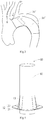
FIG. 1 is a structural schematic view showing a branch stent tube in the prior art being implanted into a fenestration site of a main stent tube; -
FIG. 2 is a structural schematic view showing the branch stent tube ofFIG. 1 becoming dislodged from the fenestration site of the main stent tube and falling into a branch vessel; -
FIG. 3 is a structural schematic view showing the branch stent tube ofFIG. 1 falling off from the fenestration site of the main stent tube and falling into the main stent tube; -
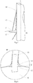
FIG. 4 is a structural schematic view of a first vascular stent according to a first embodiment of the disclosure; -
FIG. 5 is a structural schematic view of flipping trajectories of a proximal support and a distal support on the first vascular stent shown inFIG. 4 ; -
FIG. 6 is a structural schematic view showing the first vascular stent shown inFIG. 4 being implanted into the main stent tube; -
FIG. 7 is a schematic view of a portion of an internal structure of the first vascular stent shown inFIG. 4 ; -
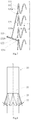
FIG. 8 is a structural schematic view of a second vascular stent according to a second embodiment of the disclosure; -
FIG. 9 is a structural schematic view of a third vascular stent according to a third embodiment of the disclosure; -
FIG. 10 is a structural schematic view of a portion D of the third vascular stent shown inFIG. 9 ; -
FIG. 11 is a structural schematic view showing the third vascular stent shown inFIG. 9 being implanted into the main stent tube; and -
FIG. 12 is a structural schematic view of the third vascular stent according to another embodiment of the disclosure. - Where, 10', branch stent tube; 20' main stent tube; 10, first vascular stent; 11, first inner stent tube; 111, first inner stent tube framework; 112, the first inner stent tube film covering; 12, first proximal support; 121, first supporting rod; 121a, first connecting end; 121b, first free end; 122, first proximal support film covering; 13, first distal support; 131, second supporting rod; 131a, second connecting end; 131b, second free end; 20, second vascular stent; 21, second inner stent tube; 22, second proximal support; 23, second distal support; 30, third vascular stent; 31, third inner stent tube; 32, third proximal support; 33, third distal support; 34, flexible connector; A, aorta tube; B, branch vessel; C, main stent tube; L, central axis; M, perpendicular to the central axis L.
- Exemplary implementations of the disclosure will be described in more detail below with reference to the accompanying drawings. Although exemplary implementations of the disclosure are shown in the drawings, it should be understood that the disclosure may be embodied in various forms and should not be limited to the implementations set forth herein. Rather, these implementations are provided so that this disclosure will be thoroughly understood, and the scope of the disclosure will be fully conveyed to those skilled in the art. It should be noted that the disclosure is described by providing a proximal support and a distal support as a rod-like structure and a connecting rod structure, but is not limited to the shape structure of the proximal support and the distal support of the disclosure. For example, the proximal support and the distal support of the disclosure may have other structures such as a folded plate-like structure, and such adjustment is within the scope of the disclosure for proximal and distal supports.
- It is to be understood that the terminology used herein is for the purpose of describing particular example implementations only and is not intended to be limiting. As used herein, the singular forms "a/an", "one" and "the" are intended to include the plural forms as well, unless the context clearly indicates otherwise. The terms "comprising", "including", "containing", and "having" are inclusive and thus specify the presence of stated features, steps, operations, elements, and/or components, but do not preclude the presence or addition of one or more other features, steps, operations, elements, components, and/or groups thereof. The method steps, processes, and operations described herein are not to be construed as necessarily requiring them to be executed in the particular order described or illustrated, unless the order of execution is explicitly indicated. It should also be understood that additional or alternative steps may be used.
- While the terms first, second, third, etc. may be used herein to describe various elements, components, regions, layers and/or sections, these elements, components, regions, layers and/or sections should not be limited by these terms. These terms may be used solely to distinguish one element, component, region, layer or section from another region, layer or section. Terms such as "first", "second" and other numerical terms used herein do not imply a sequence or order unless the context clearly dictates otherwise. Accordingly, a first element, component, region, layer or section discussed below may be referred to as a second element, component, region, layer or section without departing from the teachings of example implementations.
- For ease of description, spatially relative terms, such as "inner", "inner wall", "outer wall", "close to", "proximate", "away from", "inner side", "outer side", "below", "under", "above", "over", etc. may be used herein to describe the relationship of one element or feature to another element or feature as shown in the figures. Such spatially relative terms are intended to encompass different orientations of the apparatus in use or operation in addition to the orientation depicted in the figures. For example, if the apparatus in the figures flips or reverses, elements described as "below" or "under" other elements or features would then be oriented "above" or "over" the other elements or features. Thus, the example term "under" may include both an upper and a lower orientation. The apparatus may be otherwise oriented (rotated 90 degrees or in other directions) and the spatially relative descriptors used herein interpret accordingly.
- It should be noted that in the field of stents, it is common to refer to an end of the stent where blood flow enters the blood vessel as a "proximal" end of the stent (the direction of an arrow shown in
FIG. 1 is the direction where blood flow enters the blood vessel) and an end of the stent where blood flow exits the blood vessel as a "distal" end of the stent, and the "proximal" and "distal" ends of any component of the stent are defined in accordance with this principle. "Axial" generally refers to the lengthwise direction of the stent as it is delivered, and "radial" generally refers to the direction of the stent perpendicular to its "axial" direction, and the "axial" and "radial" directions of any component of the covered stent are defined in accordance with this principle. "Compressed configuration" refers to a configuration in which a medical device, such as a stent, is accommodated in an assembly, such as a sheath, and thus compressed during delivery; "expanded configuration" refers to a configuration in which a medical device in a compressed configuration expands in a self-expansion manner after being free from the constraint of an assembly, such as a sheath. When a device can expand in a self-expansion manner in a natural state, and is only acted upon by gravity, the configuration corresponds to a "natural configuration". - In order to describe the technical features and technical effects of the vascular stent of the disclosure in detail, the vascular stent of the disclosure is described below by three specific embodiments.
- As shown in
FIG. 4 , the present embodiment provides a firstvascular stent 10 including a firstinner stent tube 11, a firstproximal support 12, and a firstdistal support 13, the firstproximal support 12 and the firstdistal support 13 are respectively arranged on outer walls of the firstinner stent tube 11. As shown inFig. 5 , when the firstvascular stent 10 is in the compressed configuration, the firstproximal support 12 and the seconddistal support 13 are both in a folded state and positioned close to the outer wall of the first inner stent tube 11 (shown in dotted lines inFIG. 5 ); when the firstvascular stent 10 is transformed from the compressed configuration to the expanded configuration, the firstproximal support 12 expands towards the direction of a distal end of the firstvascular stent 10, and the seconddistal support 13 expands towards a proximal end of the firstvascular stent 10. - Specifically, as shown in
FIG. 6 , the firstvascular stent 10 in this embodiment is adapted to be implanted into a branch vessel B and anchored to a main stent tube C in an aorta tube A, a fenestra (not shown) is formed in the wall of the main stent tube C at a position corresponding to the branch vessel B, and after the firstvascular stent 10 is released in vivo, since the firstproximal support 12 expands towards the distal end of the firstvascular stent 10 and finally abuts against the inner wall of the main stent tube C, the firstdistal support 13 expands away from the outer wall of the firstinner stent tube 11; that is, the firstdistal support 13 expands towards the proximal end of the firstvascular stent 10 and finally abuts against the outer wall of the main stent tube C, so that the firstvascular stent 10 can be anchored at a fenestration site of the main stent tube C by means of the firstproximal support 12 and the firstdistal support 13, thereby preventing the firstvascular stent 10 from shifting or dislodging, and making the main stent tube C more stable after being implanted into the body and preventing shifting. - As shown in
FIG. 7 , a first connectingend 121 a of the firstproximal support 12 is rotatably connected to a first innerstent tube framework 111 and the first free ends 121b of the firstproximal support 12 are all directed towards the outside of the firstinner stent tube 11 and can automatically extend and abut against the inner wall side of the main stent tube C near the fenestration site after being released. The firstdistal support 13 is arranged on the outer wall of the firstvascular stent 10 and located at the outer wall side near the fenestration site of the main stent tube C, a second connectingend 131a of the firstdistal support 13 is rotatably connected to the first innerstent tube framework 111 and the second free ends 131b of the firstdistal support 13 are all directed towards the proximal end of the firstinner stent tube 11, and can automatically extend and abut against the outer wall side near the fenestration site of the main stent tube C after being released. In other embodiments, the first connectingend 121a of the firstproximal support 12 is fixedly connected to the first innerstent tube framework 111 but can automatically expand to a pre-set shape after being freed from the radial constraint of the sheath, at which time the firstfree end 121b of the firstproximal support 12 abuts against the inner wall of the main stent tube C; similarly, the second connectingend 131a of the firstdistal support 13 is fixedly connected to the first innerstent tube framework 111 but can automatically expand to a pre-set shape after being freed from the radial constraint of the sheath, at which time the secondfree end 131b of the firstdistal support 13 abuts against the outer wall of the main stent tube C. - The nickel-titanium wires are knitted and subjected to heat-setting treatment to form a metal wave ring consisting of a plurality of wave crests, a plurality of wave troughs and a plurality of side rods, and a plurality of metal wave rings are arranged along the central axis L to form the first inner
stent tube framework 111. A first inner stent tube film covering 112 is formed by sintering ePTFE, and the first inner stent tube film covering 112 is coated on the inner and outer surfaces of the first innerstent tube framework 111 to thereby form the firstinner stent tube 11. The metal wave ring can also be made of metal or polymer materials with shape memory by laser cutting. - Referring to
FIG. 4 again, the firstproximal support 12 consists of a plurality of first supportingrods 121 and a first proximal support film covering 122, the plurality of first supportingrods 121 are a plurality of rods made of metal (e.g. Nitinol) with shape memory characteristic, the plurality of first supportingrods 121 circumferentially surround the outer wall of the firstinner stent tube 11 and are spaced apart from one another. The first connecting ends 121a of the plurality of first supportingrods 121 are connected to the first innerstent tube framework 111 in a winding manner, and are heat-treated and shaped to form a preset included angle of 80° with the central axis L of the firstinner stent tube 11, and can naturally rebound to the preset angle after being released from the compressed configuration; the preset included angle ranges from 20° to 80°, and the larger the preset included angle is, the larger the surface area of the firstproximal support 12 would be, and blood flow can be better prevented from flowing through the gap between the main stent tube C and the firstinner stent tube 11, so that internal leakage is prevented. The first proximal support film covering 122 is coated on the plurality of first supportingrods 121 by means of heat treatment or sewing, and is hermetically connected to the first inner stent tube film covering 112 on the firstinner stent tube 11 at the first connecting ends 121a of the first supportingrods 121; the first proximal support film covering 122 may be one or more layers. - The first
distal support 13 consists of a plurality of second supportingrods 131 circumferentially surrounding the outer wall of the firstinner stent tube 11, and the plurality of second supportingrods 131 are spaced apart and are not connected to one another. The secondconnecting end 131a of the second supportingrod 131 is connected to the first innerstent tube framework 111 in a winding manner. The second supportingrod 131 is made of a metal material with shape memory characteristic (e.g. Nitinol material) being knitted or cut, and the second supportingrod 131 is heat-treated and shaped to form a preset included angle of 15° with the central axis L of the firstinner stent tube 11, and can naturally rebound to the preset angle after being released from the compressed configuration. - Referring to
FIGS. 5 and 6 together, when one end of the first vascular stent 10 passes through the fenestra of the main stent tube C, the first proximal support 12 of the first vascular stent 10 is located inside the main stent tube C in the aortic tube A, and the first distal support 13 of the first vascular stent 10 is located outside the main stent tube C in the branch vessel B. When the first vascular stent 10 is released in vivo, the motion trajectory of the first proximal support 12 is a large-angle flip (perpendicular M across the central axis L of the first vascular stent 10) from the proximal end of the first vascular stent 10 to the distal end of the first vascular stent 10; until the first free end 121b of the first proximal support 12 abuts against the inner wall of the main stent tube C, the motion trajectory of the first distal support 13 is that its second free end 131b drives the first distal support 13 to expand at a small angle in a direction away from the outer wall of the first vascular stent 10; until the second free end 131b of the first distal support 13 abuts against the outer wall of the main stent tube C, so that the first vascular stent 10 is anchored to the main stent tube C, avoiding shifting of the first vascular stent 10 relative to the main stent tube C. - When the first
vascular stent 10 is in the compressed configuration, the firstproximal support 12 and the firstdistal support 13 on the firstvascular stent 10 are both folded and positioned close to the outer wall of the firstvascular stent 10, so that the firstvascular stent 10 can be smoothly delivered in the body after being accommodated in a sheath of a delivery device. After the firstvascular stent 10 is delivered to the target area in the blood vessel by the delivery device to be released, the firstproximal support 12 and the firstdistal support 13 on the firstvascular stent 10 are restored to their respective expanded states due to the shape memory, so that the firstvascular stent 10 is anchored to the main stent tube C in the blood vessel, and the firstvascular stent 10 is unlikely to experience shifting or become dislodged. - In another embodiment, the lengths of the plurality of second supporting
rods 131 on the firstdistal support 13 may be the same or different, and the plurality of second free ends 131b of the plurality of second supportingrods 131 may still abut against the outer wall of the main stent tube C when the angle of inclination of the branch vessel B with respect to the aorta vessel A is large. - The plurality of first supporting
rods 121 of the firstproximal support 12 and the plurality of second supportingrods 131 of the firstdistal support 13 may be distributed in one-to-one correspondence along the circumferential direction of the firstvascular stent 10, respectively, and may be staggered. The total number of first supportingrods 121 on the firstproximal support 12 may or may not be equal to the total number of second supportingrods 131 on the firstdistal support 13. In the present embodiment, the total number of the first supportingrods 121 may be between 3-15, the total number of the second supportingrods 131 may be between 3-15, and in another embodiment, the total number of the second supportingrods 131 and the total number of the first supportingrods 121 are equal, and may be between 6-8. - The length of the first supporting
rod 121 may be between 2-8 mm, the length of the second supportingrod 131 may be between 2-10 mm, and for example, the length of the first supportingrod 121 and the length of the second supportingrod 131 may both be between 3-5 mm. As used herein, the term "length" refers to the shortest distance from the first connectingend 121a to the firstfree end 121b when the first supportingrod 121 is a special-shaped rod or the shortest distance from the second connectingend 131a to the secondfree end 131b when the second supportingrod 131 is a special-shaped rod. - With continued reference to
FIG. 7 , in the expanded or natural configuration, a minimum included angle a (the minimum included angle between the firstdistal support 13 and the central axis L when in the expanded configuration) between the second supportingrod 131 on the firstdistal support 13 and the central axis L of the firstinner stent tube 11 ranges from 5° to 30°, for example, the minimum included angle a is 10°; and a minimum angle b (the minimum angle between the first supportingrod 121 and the firstinner stent tube 11 when in the expanded configuration) between the first supportingrod 121 on the firstproximal support 12 and the central axis L of the firstinner stent tube 11 ranges from 20° to 80°, for example, the minimum angle b is 75°. The setting of angles is such that the firstdistal support 13 better fits with the firstproximal support 12 to be clamped against the wall of the main stent tube C near the fenestration site, thereby preventing the firstvascular stent 10 from shifting or becoming dislodged, and reducing the probability that the main stent tube C shifts. - In the expanded configuration of the first
vascular stent 10, the firstfree end 121b of the firstproximal support 12 is closer to the distal end of the firstvascular stent 10 than the secondfree end 131b of the firstdistal support 13 so that the firstproximal support 12 and the firstdistal support 13 can be better clamped against the wall of the main stent tube C. - The first
proximal support 12 on the firstvascular stent 10 can abut against the inner wall side of the main stent tube C near the fenestration site by an outward opening motion (equivalent to turning over), and through the first proximal support film covering 112, the gap existing between the firstvascular stent 10 and the main stent tube C can be reduced, so as to avoid internal leakage of blood. Further, as shown inFIG. 7 , by setting the preset included angle b between the firstproximal support 12 and the central axis L of the firstinner stent tube 11 to be less than 80°, the firstproximal support 12 can better abut against the inner wall of the main stent tube C. Further, by appropriately reducing the preset included angle b and increasing the rod diameter of the first supportingrod 121, the supporting force between the firstproximal support 12 and the main stent tube C can be effectively increased, and specifically, the smaller the preset included angle b, the larger the amount of deformation of the firstproximal support 12 when the firstproximal support 12 abuts the main stent tube C and the greater the force of the firstproximal support 12 against the main stent tube C in the direction towards the branch vessel B; meanwhile, the greater the rod diameter of the first supportingrod 121, the greater the elastic force of the firstproximal support 121, and the greater the force of the firstproximal support 12 against the main stent tube C after it is attached to the main stent tube C. - With continued reference to
FIG. 6 , further, when the firstproximal support 12 abuts against the inner wall of the main stent tube C, the reaction force of the main stent tube C against the firstproximal support 12 risks shifting of the firstvascular stent 10 towards the aortic tube A; so in order to avoid the risk, after the firstvascular stent 10 of this embodiment is released in the branch vessel B, the second free ends 131b of the plurality of second supportingrods 131 on the firstvascular stent 10 expand in a direction away from the outer wall of the firstinner stent tube 11 and are supported at the outer wall side of the main stent tube C near the fenestration site, thereby achieving the purpose of anchoring the firstvascular stent 10 to the main stent tube C, and reducing the probability that the firstvascular stent 10 shifts towards the aortic tube A. - With continued reference to
FIG. 7 , in particular, in order for the firstdistal support 13 to effectively fit with the main stent tube C, the shortest distance between the secondfree end 131b of the firstdistal support 13 and the first connectingend 121a of the firstproximal support 12 in the direction of the central axis L should be greater than 0, and in the natural configuration, the firstfree end 121a of the firstproximal support 12 is closer to the distal end of the firstvascular stent 10 than the secondfree end 131b of the firstdistal support 13. It will be understood by those skilled in the art that the second supportingrod 131 is not limited to a straight rod, for example, the second supportingrod 131 may be a special-shaped rod body. Further, the surface of the firstdistal support 13 may be covered with a film material as well, so that the firstdistal support 13 has a sealing effect on the basis of having an anchoring function to further prevent internal leakage. - The same parts of the second
vascular stent 20 ofEmbodiment 2 as those of the firstvascular stent 10 of Embodiment 1 will not be described in detail here, and the main difference between them is that, as shown inFIG. 8 , thisEmbodiment 2 provides asecond stent 20 consisting of a secondinner stent tube 21, a secondproximal support 22 and a seconddistal support 23, where the secondproximal support 22 and the seconddistal support 23 are each composed of a plurality of V-shaped connecting rods, which may be formed by knitting nickel-titanium wires, or by cutting and heat-setting nickel-titanium tubes, and which may be connected to one another or may be provided on the secondinner stent tube 21 at intervals. At least a layer of film is provided on each of the plurality of V-shaped connecting rods of the secondproximal support 22 and the plurality of V-shaped connecting rods of the seconddistal support 23 to prevent internal leakage. The connecting ends of the plurality of V-shaped connecting rods can be connected to the secondinner stent tube 21 through winding, welding and the like, the free ends of the plurality of V-shaped connecting rods are far away from the secondinner stent tube 21 when the plurality of V-shaped connecting rods expand in a self-expansion manner, and specifically, the free ends of the plurality of V-shaped connecting rods are far away from the secondinner stent tube 21 in a natural configuration or in an expanded configuration. The plurality of V-shaped connecting rods of the secondproximal support 22 are circumferentially distributed on the outer wall of the secondinner stent tube 21, and form an included angle of 70° with the central axis L of the secondinner stent tube 21, and the plurality of V-shaped connecting rods of the seconddistal support 23 are circumferentially distributed on the outer wall of the secondinner stent tube 21 and form an included angle of 10° with the central axis L of the secondinner stent tube 21. - In another embodiment, the plurality of V-shaped connecting rods of the second
distal support 23 may be a metal framework without a film material, and the metal framework may be formed by connecting 3 to 10 V-shaped connecting rods along the outer wall of the secondinner stent tube 21, for example, the metal framework may be formed by 5 V-shaped connecting rods. The plurality of V-shaped connecting rods of the secondproximal support 22 and the plurality of V-shaped connecting rods of the seconddistal support 23 may be distributed in one-to-one correspondence along the circumferential direction of the secondinner stent tube 21, and may be staggered along the circumferential direction of the secondinner stent tube 21, and meanwhile, the number of V-shaped connecting rods in the secondproximal support 22 and the number of V-shaped connecting rods in the seconddistal support 23 may be equal or unequal. Further, the plurality of V-shaped connecting rods of the secondproximal support 22 and the plurality of V-shaped connecting rods of the seconddistal support 23 may be the same or different in size, and when each of the plurality of V-shaped connecting rods is different in size, the plurality of V-shaped connecting rods are capable of anchoring the secondvascular stent 10 to the main stent tube when the secondvascular stent 10 is tilted relative to the main stent tube. - The V-shaped connecting rod of this
Embodiment 2 has a larger supporting surface and supporting force than a single supporting rod, and therefore, the secondproximal support 22 and the seconddistal support 23 of thisEmbodiment 2 can provide better stability after the secondvascular stent 20 is implanted into a target area in the body. Each of the V-shaped connecting rods in thisEmbodiment 2 has one free end and two connecting ends, so that the plurality of V-shaped connecting rods connected with one another can ensure that the anchoring effect of the secondproximal supporter 22 and the seconddistal supporter 23 is not affected by the local deformation of the V-shaped connecting rods when the respective free ends are unilaterally stressed in a bent blood vessel or under compression. - In another embodiment, the second
proximal support 22 and the seconddistal support 23 may each be composed of a plurality of corrugated connecting rods, which differ from V-shaped connecting rods in that the corrugated connecting rods are rods with corrugated shape. The implementations of the corrugated connecting rod are similar to those of the V-shaped connecting rod, and therefore, a detailed description thereof will be omitted. - The same parts of the third
vascular stent 30 of Embodiment 3 as those of the firstvascular stent 10 of Embodiment 1 will not be described in detail here, and the main difference between them is that, as shown inFIGS. 9 and 10 , Embodiment 3 provides athird stent 30 consisting of a thirdinner stent tube 31, a thirdproximal support 32 and a thirddistal support 33, where the thirdproximal support 32 is provided with at least a layer of film to prevent internal leakage. The thirdproximal support 32 and the thirddistal support 33 may be composed of a plurality of single supporting rod frames; the connecting end of the thirdproximal support 32 is connected to the free end of the thirddistal support 33 by aflexible connector 34, which may be formed of a film material, for example, theflexible connector 34 integrally covers the metal framework of the thirdproximal support 32; and the metal framework of the thirddistal support 33 spaced apart from the thirdproximal support 32, and the thirdproximal support 32 and the thirddistal support 33 are welded to form a unitary supporting structure. The metal framework of the thirdproximal support 32 is not in direct contact with the metal framework of the thirddistal support 33; and a maximum distance X between them, i.e. the length of theflexible connection 34 is greater than 0 mm and less than or equal to 2 mm, for example the length of theflexible connection 34 is 2 mm. If theflexible connector 34 is not provided, the connecting end of the thirdproximal support 32 is directly connected to the free end of the thirddistal support 33, and then the thirddistal support 33 cannot expand after being released, and the thirdproximal support 32 cannot serve as an anchor. If the length of theflexible connector 34 is greater than 2 mm, the anchoring effect of the thirdproximal support 32 may be affected, or even the thirdproximal support 32 cannot serve as an anchor because theflexible connector 34 is too long. - As shown in
FIG. 11 , a portion of the thirdvascular stent 30 is implanted into the branch vessel through the fenestration on the main stent tube C. After releasing the thirdvascular stent 30, the thirdproximal support 32 abuts the inner wall of the main stent tube C near the fenestration site by expanding towards the distal end of the thirdvascular stent 30, and theflexible connector 34 is located at the fenestra edge of the main stent tube C; then, the thirddistal support 33 abuts against the outer wall of the main stent tube C near the fenestration site by expanding outwardly in a direction away from the outer wall of the thirdinner stent tube 31. Since the end of the thirddistal support 33 connected to theflexible connector 34 abuts against the outer wall of the main stent tube C, the free end of the thirdproximal support 32 abuts against the inner wall of the main stent tube C, thereby anchoring the thirdvascular stent 30 to the main stent tube C, preventing the thirdvascular stent 30 from shifting or becoming dislodged, and meanwhile avoiding internal leakage. It should be noted that since there is no rigid connection between the thirddistal support 33 and the thirdproximal support 32, and theflexible connector 34 has a certain deformability, theflexible connector 34 causes less resistance to the thirdproximal support 32 and the thirddistal support 33 during expansion of the thirdproximal support 32 and the thirddistal support 33, thereby facilitating smooth expansion of the thirdproximal support 32 and the thirddistal support 33. - The connecting end of the third
proximal support 32 is connected to the free end of the thirddistal support 33, so that the thirdproximal support 32 in this Embodiment 3 can be expanded more fully, covering a larger area, thereby enhancing the anchoring stability of the thirdvascular stent 30. At the same time, theflexible connector 34 between the connecting end of the thirdproximal support 32 and the free end of the thirddistal support 33 also improves the sealability of thethird stent 30 to prevent internal leakage. - The third
distal support 33 may be composed of a plurality of single supporting rods, the thirddistal support 33 serves as a unilateral anchor for the thirdvascular stent 30, and the implementation of the thirddistal support 33 is the same as that of the firstdistal support 13 in Embodiment 1 and will not be described in detail herein. - The third
proximal support 32 and the thirddistal support 33 may be connected by theflexible connector 34 formed of a polymer wire such as PTFE, polyester, and polypropylene. The lengths of the plurality of connecting rods in the thirddistal support 33 may be the same or different, and the connecting rods may be circumferentially spaced or continuously uniformly or non-uniformly distributed along the outer wall of the thirdinner stent tube 31, so that the thirddistal support 33 and the thirdproximal support 32 can maintain anchoring stability when thethird stent 30 is in a complex environment. - As shown in
FIG. 12 , in another embodiment, the thirdproximal support 32 and the thirddistal support 33 may each be composed of a plurality of V-shaped connecting rods, the connecting ends of the V-shaped connecting rods of the thirdproximal support 32 and the free ends of the V-shaped connecting rods of the thirddistal support 33 are connected by a flexible connector, and the V-shaped connecting rods have better anchoring stability relative to the single supporting rods. The implementation in which the thirdproximal support 32 and the thirddistal support 33 are provided as V-shaped connecting rods is similar to the implementation in which the thirdproximal support 32 and the thirddistal support 33 are provided as single supporting rods, and will not be described in detail herein. Further, at least one coating layer of film may be provided on the thirddistal support 33 to improve the sealability of thethird stent 30 to further prevent internal leakage. - It should be noted that each structure on each vascular stent described in Embodiment 1,
Embodiment 2 and Embodiment 3 can be reasonably combined according to the actual application environment, and the combined vascular stent can include one or more of the above-mentioned technical features and has the technical effects of each technical feature, so that the combined vascular stent falls within the protection scope of the vascular stent of the disclosure. - The above description is only preferred implementations of the disclosure and the protection scope of the disclosure is not limited thereto. Any modifications and substitutions that those skilled in the art can easily think of fall within the technical scope disclosed by the disclosure Accordingly, the protection scope of the disclosure shall be subject to the protection scope defined by the claims.
Claims (10)
- A vascular stent, comprising: an inner stent tube as well as a proximal support and a distal support which are disposed on an outer wall of the inner stent tube, when the vascular stent is in a compressed configuration, the proximal support and the distal support are both folded and close to the outer wall of the inner stent tube; and when the vascular stent is expanded from the compressed configuration to an expanded configuration, a free end of the proximal support expands towards a distal end of the vascular stent, and a free end of the distal support expands towards a proximal end of the vascular stent.
- The vascular stent according to claim 1, wherein the proximal support comprises a plurality of first supports disposed along a circumferential direction of the inner stent tube, connecting ends of the plurality of first supports are each connected to the outer wall of the inner stent tube, and free ends of the plurality of first supports are each directed towards an outside of the inner stent tube.
- The vascular stent according to claim 2, wherein a minimum included angle between a straight line or plane in which the first support is located and a central axis of the vascular stent ranges from 20° to 80° in the expanded configuration or a natural configuration.
- The vascular stent according to claim 2, wherein the proximal support is provided with at least a layer of film.
- The vascular stent according to claim 1, wherein the distal support comprises a plurality of second supports disposed along a circumferential direction of the inner stent tube, connecting ends of the plurality of second supports are each connected to the outer wall of the inner stent tube, and free ends of the plurality of second supports are each directed towards a proximal end of the inner stent tube.
- The vascular stent according to claim 5, wherein a minimum included angle between a straight line or plane in which the second support is located and the central axis of the vascular stent ranges from 5° to 30° in the expanded configuration or the natural configuration.
- The vascular stent according to claim 1, wherein in the expanded configuration, the free end of the proximal support is closer to the distal end of the vascular stent than the free end of the distal support.
- The vascular stent according to claim 1, wherein the free end of the distal support is connected to the connecting end of the proximal support by means of a flexible connector, and the free end of the proximal support expands towards the distal end of the vascular stent during expansion.
- The vascular stent according to claim 8, wherein the flexible connector is a film, both ends of which cover the proximal support and the distal support, respectively.
- The vascular stent according to claim 9, wherein a length of the flexible connector is greater than 0 mm and less than or equal to 2 mm.
Applications Claiming Priority (2)
| Application Number | Priority Date | Filing Date | Title |
|---|---|---|---|
| CN201811625677.9A CN109700567B (en) | 2018-12-28 | 2018-12-28 | Blood vessel support |
| PCT/CN2019/110124 WO2020134317A1 (en) | 2018-12-28 | 2019-10-09 | Vascular stent |
Publications (3)
| Publication Number | Publication Date |
|---|---|
| EP3903729A1 true EP3903729A1 (en) | 2021-11-03 |
| EP3903729A4 EP3903729A4 (en) | 2022-09-28 |
| EP3903729B1 EP3903729B1 (en) | 2026-01-28 |
Family
ID=66259200
Family Applications (1)
| Application Number | Title | Priority Date | Filing Date |
|---|---|---|---|
| EP19903169.1A Active EP3903729B1 (en) | 2018-12-28 | 2019-10-09 | Vascular stent |
Country Status (4)
| Country | Link |
|---|---|
| US (1) | US11730615B2 (en) |
| EP (1) | EP3903729B1 (en) |
| CN (1) | CN109700567B (en) |
| WO (1) | WO2020134317A1 (en) |
Families Citing this family (5)
| Publication number | Priority date | Publication date | Assignee | Title |
|---|---|---|---|---|
| CN109700567B (en) | 2018-12-28 | 2020-08-11 | 深圳市先健畅通医疗有限公司 | Blood vessel support |
| CN110420079B (en) * | 2019-06-28 | 2022-03-08 | 深圳市先健畅通医疗有限公司 | Lumen Stents and Lumen Stent Systems |
| WO2022116593A1 (en) * | 2020-12-02 | 2022-06-09 | 先健科技(深圳)有限公司 | Covered stent |
| CN115814260B (en) * | 2022-12-28 | 2023-12-29 | 心擎医疗(苏州)股份有限公司 | A catheter pump with auxiliary diversion |
| KR102754821B1 (en) * | 2023-05-24 | 2025-01-21 | (주)태웅메디칼 | Anti-migration stent |
Family Cites Families (17)
| Publication number | Priority date | Publication date | Assignee | Title |
|---|---|---|---|---|
| US6599316B2 (en) | 1996-11-04 | 2003-07-29 | Advanced Stent Technologies, Inc. | Extendible stent apparatus |
| NL1014559C2 (en) | 2000-02-11 | 2001-08-14 | Surgical Innovations Vof | Umbrella stent. |
| US7044962B2 (en) | 2002-06-25 | 2006-05-16 | Scimed Life Systems, Inc. | Implantable prosthesis with displaceable skirt |
| US20090264985A1 (en) * | 2008-04-17 | 2009-10-22 | Medtronic Vascular, Inc. | Branch Vessel Suture Stent System and Method |
| EP2453836A4 (en) * | 2009-07-14 | 2016-02-17 | Endospan Ltd | Sideport engagement and sealing mechanism for endoluminal stent-grafts |
| DK2663258T3 (en) * | 2011-01-11 | 2019-03-11 | Hans Reiner Figulla | PROTEST VALVE TO REPLACE AN ATRIOVENTRICULAR HEART VALVE |
| WO2012177942A2 (en) * | 2011-06-21 | 2012-12-27 | Hanson Gifford, Iii | Prosthetic heart valve devices and associated systems and methods |
| FR2979228B1 (en) * | 2011-08-22 | 2014-08-29 | Ct Hospitalier Universitaire Nimes | UNIVERSAL AORTIC ENDOPROTHESIS |
| US20140046347A1 (en) | 2012-08-10 | 2014-02-13 | W. L. Gore & Associates, Inc. | Devices, systems and methods for engaging tissue |
| KR20140094144A (en) * | 2013-01-21 | 2014-07-30 | 주식회사 엠아이텍 | Stent for preventing migration and apparatus and method thereof |
| CN110393608B (en) * | 2013-03-15 | 2023-02-17 | 心脏结构导航公司 | Catheter-guided valve replacement devices and methods |
| GB2515731A (en) * | 2013-06-18 | 2015-01-07 | Vascutek Ltd | Prosthesis |
| US10456243B2 (en) * | 2015-10-09 | 2019-10-29 | Medtronic Vascular, Inc. | Heart valves prostheses and methods for percutaneous heart valve replacement |
| CN105559944B (en) | 2015-12-14 | 2016-11-09 | 李雷 | Film-coated vascular support |
| CN107822739B (en) | 2016-09-07 | 2020-03-24 | 先健科技(深圳)有限公司 | Lumen Stents and Lumen Stent Systems |
| CN108261250B (en) * | 2016-12-30 | 2019-12-10 | 先健科技(深圳)有限公司 | Anti-endoleak stent graft system |
| CN109700567B (en) * | 2018-12-28 | 2020-08-11 | 深圳市先健畅通医疗有限公司 | Blood vessel support |
-
2018
- 2018-12-28 CN CN201811625677.9A patent/CN109700567B/en active Active
-
2019
- 2019-10-09 US US17/418,648 patent/US11730615B2/en active Active
- 2019-10-09 WO PCT/CN2019/110124 patent/WO2020134317A1/en not_active Ceased
- 2019-10-09 EP EP19903169.1A patent/EP3903729B1/en active Active
Also Published As
| Publication number | Publication date |
|---|---|
| US20220079783A1 (en) | 2022-03-17 |
| EP3903729B1 (en) | 2026-01-28 |
| EP3903729A4 (en) | 2022-09-28 |
| CN109700567A (en) | 2019-05-03 |
| CN109700567B (en) | 2020-08-11 |
| WO2020134317A1 (en) | 2020-07-02 |
| US11730615B2 (en) | 2023-08-22 |
Similar Documents
| Publication | Publication Date | Title |
|---|---|---|
| US11730615B2 (en) | Vascular stent | |
| JP4607579B2 (en) | Segmental graft embedded stent | |
| US12551328B2 (en) | Device for anastomotic bypass | |
| US8808351B2 (en) | Stretchable prosthesis fenestration | |
| US9770350B2 (en) | Stent-graft with fixation elements that are radially confined for delivery | |
| US20070219610A1 (en) | Stent with flap | |
| US20080262601A1 (en) | Stent Device with Multiple Helix Construction | |
| WO2003057079A1 (en) | Prosthesis implantable in enteral vessels | |
| JP2008503270A (en) | Medical stent | |
| US20110166640A1 (en) | Stent having less invasive ends and improved radial force | |
| US20110040369A1 (en) | Implantable Medical Device | |
| US20240341944A1 (en) | Stent with atraumatic spacer | |
| JP6992076B2 (en) | Devices for Forming Venous Valves and Related Percutaneous Minimal Invasive Methods | |
| JP7185739B2 (en) | stent graft | |
| CN109890328A (en) | Double bracket | |
| KR101772482B1 (en) | Anti-migration stent | |
| CN116407335A (en) | Stent Graft and Stent Graft Delivery System | |
| KR20170021916A (en) | Devices and methods for securing medical devices within an anatomy | |
| CN108261254B (en) | Bifurcated stent graft | |
| CN117281660A (en) | Vascular tectorial membrane support | |
| CN111228001B (en) | Lumen stent and in-situ windowing stent system | |
| CN109730804B (en) | Covered stent | |
| CN114681116A (en) | Lumen stent | |
| CN216854951U (en) | Lumen stent and lumen stent system | |
| JPWO2020105579A1 (en) | Tubular indwelling tool |
Legal Events
| Date | Code | Title | Description |
|---|---|---|---|
| STAA | Information on the status of an ep patent application or granted ep patent |
Free format text: STATUS: THE INTERNATIONAL PUBLICATION HAS BEEN MADE |
|
| PUAI | Public reference made under article 153(3) epc to a published international application that has entered the european phase |
Free format text: ORIGINAL CODE: 0009012 |
|
| STAA | Information on the status of an ep patent application or granted ep patent |
Free format text: STATUS: REQUEST FOR EXAMINATION WAS MADE |
|
| 17P | Request for examination filed |
Effective date: 20210723 |
|
| AK | Designated contracting states |
Kind code of ref document: A1 Designated state(s): AL AT BE BG CH CY CZ DE DK EE ES FI FR GB GR HR HU IE IS IT LI LT LU LV MC MK MT NL NO PL PT RO RS SE SI SK SM TR |
|
| DAV | Request for validation of the european patent (deleted) | ||
| DAX | Request for extension of the european patent (deleted) | ||
| A4 | Supplementary search report drawn up and despatched |
Effective date: 20220825 |
|
| RIC1 | Information provided on ipc code assigned before grant |
Ipc: A61F 2/856 20130101ALI20220819BHEP Ipc: A61F 2/07 20130101AFI20220819BHEP |
|
| RAP1 | Party data changed (applicant data changed or rights of an application transferred) |
Owner name: LIFETECH SCIENTIFIC (SHENZHEN) CO., LTD. |
|
| RAP1 | Party data changed (applicant data changed or rights of an application transferred) |
Owner name: LIFETECH SCIENTIFIC (SHENZHEN) CO., LTD. |
|
| GRAP | Despatch of communication of intention to grant a patent |
Free format text: ORIGINAL CODE: EPIDOSNIGR1 |
|
| STAA | Information on the status of an ep patent application or granted ep patent |
Free format text: STATUS: GRANT OF PATENT IS INTENDED |
|
| RIC1 | Information provided on ipc code assigned before grant |
Ipc: A61F 2/07 20130101AFI20250831BHEP Ipc: A61F 2/856 20130101ALI20250831BHEP |
|
| INTG | Intention to grant announced |
Effective date: 20250912 |
|
| GRAS | Grant fee paid |
Free format text: ORIGINAL CODE: EPIDOSNIGR3 |
|
| GRAA | (expected) grant |
Free format text: ORIGINAL CODE: 0009210 |
|
| STAA | Information on the status of an ep patent application or granted ep patent |
Free format text: STATUS: THE PATENT HAS BEEN GRANTED |
|
| P01 | Opt-out of the competence of the unified patent court (upc) registered |
Free format text: CASE NUMBER: UPC_APP_0015708_3903729/2025 Effective date: 20251203 |
|
| AK | Designated contracting states |
Kind code of ref document: B1 Designated state(s): AL AT BE BG CH CY CZ DE DK EE ES FI FR GB GR HR HU IE IS IT LI LT LU LV MC MK MT NL NO PL PT RO RS SE SI SK SM TR |
|
| REG | Reference to a national code |
Ref country code: CH Ref legal event code: F10 Free format text: ST27 STATUS EVENT CODE: U-0-0-F10-F00 (AS PROVIDED BY THE NATIONAL OFFICE) Effective date: 20260128 Ref country code: GB Ref legal event code: FG4D |
|
| REG | Reference to a national code |
Ref country code: DE Ref legal event code: R096 Ref document number: 602019080982 Country of ref document: DE |
|
| REG | Reference to a national code |
Ref country code: IE Ref legal event code: FG4D |