EP3903638A1 - Set of elements perfected for joining a plinth to the foot of a piece of furniture or the like - Google Patents
Set of elements perfected for joining a plinth to the foot of a piece of furniture or the like Download PDFInfo
- Publication number
- EP3903638A1 EP3903638A1 EP21171143.7A EP21171143A EP3903638A1 EP 3903638 A1 EP3903638 A1 EP 3903638A1 EP 21171143 A EP21171143 A EP 21171143A EP 3903638 A1 EP3903638 A1 EP 3903638A1
- Authority
- EP
- European Patent Office
- Prior art keywords
- support element
- base
- foot
- magnet
- hooking
- Prior art date
- Legal status (The legal status is an assumption and is not a legal conclusion. Google has not performed a legal analysis and makes no representation as to the accuracy of the status listed.)
- Withdrawn
Links
- 238000005304 joining Methods 0.000 title claims abstract description 12
- 230000005291 magnetic effect Effects 0.000 claims abstract description 41
- 230000005294 ferromagnetic effect Effects 0.000 claims abstract description 15
- 229910052751 metal Inorganic materials 0.000 claims abstract description 15
- 239000002184 metal Substances 0.000 claims abstract description 15
- 239000007769 metal material Substances 0.000 claims abstract description 15
- 210000003811 finger Anatomy 0.000 claims abstract description 11
- 210000003813 thumb Anatomy 0.000 claims abstract description 8
- 238000003780 insertion Methods 0.000 claims description 13
- 230000037431 insertion Effects 0.000 claims description 13
- 239000000463 material Substances 0.000 claims description 11
- 239000003302 ferromagnetic material Substances 0.000 claims description 9
- 230000000717 retained effect Effects 0.000 claims description 4
- 230000000295 complement effect Effects 0.000 claims description 3
- 230000008878 coupling Effects 0.000 description 24
- 238000010168 coupling process Methods 0.000 description 24
- 238000005859 coupling reaction Methods 0.000 description 24
- 238000000605 extraction Methods 0.000 description 5
- 238000011161 development Methods 0.000 description 4
- 238000004519 manufacturing process Methods 0.000 description 4
- 239000000853 adhesive Substances 0.000 description 3
- 230000001070 adhesive effect Effects 0.000 description 3
- 238000012937 correction Methods 0.000 description 3
- XEEYBQQBJWHFJM-UHFFFAOYSA-N Iron Chemical compound [Fe] XEEYBQQBJWHFJM-UHFFFAOYSA-N 0.000 description 2
- 230000004913 activation Effects 0.000 description 2
- 230000003466 anti-cipated effect Effects 0.000 description 2
- 230000000903 blocking effect Effects 0.000 description 2
- 230000005484 gravity Effects 0.000 description 2
- 238000009434 installation Methods 0.000 description 2
- 238000000034 method Methods 0.000 description 2
- 239000004033 plastic Substances 0.000 description 2
- 239000000243 solution Substances 0.000 description 2
- 239000002023 wood Substances 0.000 description 2
- 230000001154 acute effect Effects 0.000 description 1
- 229910052782 aluminium Inorganic materials 0.000 description 1
- XAGFODPZIPBFFR-UHFFFAOYSA-N aluminium Chemical compound [Al] XAGFODPZIPBFFR-UHFFFAOYSA-N 0.000 description 1
- 238000005452 bending Methods 0.000 description 1
- 238000012512 characterization method Methods 0.000 description 1
- 239000011093 chipboard Substances 0.000 description 1
- 238000004140 cleaning Methods 0.000 description 1
- 238000010276 construction Methods 0.000 description 1
- 238000005520 cutting process Methods 0.000 description 1
- 230000001419 dependent effect Effects 0.000 description 1
- 238000009792 diffusion process Methods 0.000 description 1
- 230000000694 effects Effects 0.000 description 1
- 239000003000 extruded plastic Substances 0.000 description 1
- 238000001125 extrusion Methods 0.000 description 1
- 239000000945 filler Substances 0.000 description 1
- 210000000003 hoof Anatomy 0.000 description 1
- 238000001746 injection moulding Methods 0.000 description 1
- 230000003993 interaction Effects 0.000 description 1
- 229910052742 iron Inorganic materials 0.000 description 1
- 239000000696 magnetic material Substances 0.000 description 1
- 238000000465 moulding Methods 0.000 description 1
- 238000012545 processing Methods 0.000 description 1
- 230000001105 regulatory effect Effects 0.000 description 1
- 238000010079 rubber tapping Methods 0.000 description 1
- 230000035807 sensation Effects 0.000 description 1
- 239000000126 substance Substances 0.000 description 1
- 229920001169 thermoplastic Polymers 0.000 description 1
- 239000004416 thermosoftening plastic Substances 0.000 description 1
Images








Classifications
-
- A—HUMAN NECESSITIES
- A47—FURNITURE; DOMESTIC ARTICLES OR APPLIANCES; COFFEE MILLS; SPICE MILLS; SUCTION CLEANERS IN GENERAL
- A47B—TABLES; DESKS; OFFICE FURNITURE; CABINETS; DRAWERS; GENERAL DETAILS OF FURNITURE
- A47B95/00—Fittings for furniture
- A47B95/002—Plinths, e.g. between furniture and ceiling or wall
-
- A—HUMAN NECESSITIES
- A47—FURNITURE; DOMESTIC ARTICLES OR APPLIANCES; COFFEE MILLS; SPICE MILLS; SUCTION CLEANERS IN GENERAL
- A47B—TABLES; DESKS; OFFICE FURNITURE; CABINETS; DRAWERS; GENERAL DETAILS OF FURNITURE
- A47B95/00—Fittings for furniture
- A47B95/002—Plinths, e.g. between furniture and ceiling or wall
- A47B2095/004—Base plinths
Definitions
- the present invention relates to an improved set of elements for joining at least one base to the foot of a piece of furniture or the like.
- the application of these devices first involves fixing them to the base and positioning them so as to be frontally aligned with the corresponding feet of the piece of furniture. Subsequently, the base is brought closer to the feet and, by operating an appropriate pressure, the elastic fins are elastically deformed to allow them to embrace the foot.
- This device has been on the market for a long time and is already widely appreciated for its qualities, however it is not optimal for hooking the feet positioned at the corners of the furniture.
- the bases are connected to each other by means of a corner piece having a cross section that has a hollow central portion of a substantially square or rectangular shape. Furthermore, from the hollow portion some sides branch off, two by two parallel, which laterally define the respective seats within which the leading edges of the two baseboards to be joined fit together.
- the object of the invention is to propose a set of elements for joining the bases of a piece of furniture or the like which allows to overcome, at least in part, the drawbacks of the known solutions.
- Another object of the invention is to propose a set of elements which allows to obtain a pleasant overall aesthetic effect and which gives the observer the sensation of being in front of a high quality product, both from an aesthetic and functional point of view.
- Another object of the invention is to propose a set of elements which allows a simple, easy, quick and precise assembly and junction of the bases, without the need to carry out continuous corrections.
- Another object of the invention is to propose a set of elements which allows the installer not to be bound by the inaccuracies in the construction and processing (cutting) of the bases.
- Another object of the invention is to propose a set of elements which has an alternative characterization, both in constructive and functional terms, with respect to the traditional ones.
- Another object of the invention is to propose a set of elements which can be obtained simply, quickly and with low costs.
- Another object of the invention is to propose a set of elements that can be mass-produced quickly and efficiently.
- Another object of the invention is to propose a set of elements that can be easily used also at the corners of the piece of furniture.
- Another object of the invention is to propose a set of elements that have high standards, both functional and aesthetic, and at the same time of accessible cost, thus allowing the possibility of its diffusion on a large scale.
- the assembly 2 for joining a first base 4 and/or a second base 4' to a foot 6 of a piece of furniture or the like, comprises a hooking element 12, which is configured to be removably associated with the foot 6 of the piece of furniture or the like.
- the hooking element 12 is made at least in part of magnetic metal material, preferably ferromagnetic, or of magnetized material (ie a magnet).
- the assembly 2 further comprises a first support element 8 for a first magnet 10, which is configured to be magnetically connected to the hooking element 12; suitably, the first support element 8 is also configured to be associated, preferably removably, with the first base 4.
- the assembly 2 according to the invention further comprises a second support element 8' for a second magnet 10', which is configured to be magnetically connected to the hooking element 12.
- the second support element 8' is configured to be associated, preferably removably, with the second base 4', which is intended to be positioned at an angle with respect to the first base 4, preferably orthogonal with respect to the first base 4'.
- the second support element 8' can be substantially congruent and interchangeable with the first support element 8. For this reason, all the characteristics described below with particular reference to the first support element 8, are to be understood as described, mutatis mutandis, also for the second support element 8'.
- the assembly can also comprise a connecting element 3 intended to be arranged in correspondence with a contact area between the first base 4 and the second base 4'.
- a connecting element 3 intended to be arranged in correspondence with a contact area between the first base 4 and the second base 4'.
- at least the first support element 8 is configured to cooperate with the connecting element 3 to keep said connecting element 3 associated with the first base 4'.
- both the first and the second support element 8, 8' are configured to cooperate with the connecting element 3 to maintain the same connecting element 3 associated with the respective first base 4 and second base 4'.
- first base 4, the second base 4' and/or the foot 6 can be substantially of the traditional type, per se known to those skilled in the art.
- first and/or second support element 8, 8' is provided with a shaped protrusion 16' configured to be inserted and then rotated, in particular by about 90°, inside a channel 14 obtained respectively in said first base 4 or in said second base 4'.
- a pair of gripping portions 33, 33' are defined on the first and/or second support element 8, 8' configured to allow a user to grip with the thumb and another finger of the same hand respectively, to thus facilitate the rotation of said shaped protrusion 16' of said first and/or second support element 8, 8' inside the channel 14 obtained respectively in said first base 4 or in said second base 4'.
- the first and/or second support element 8, 8' is provided with a bayonet coupling 16, defined by said shaped protrusion 16', to removably associate the first or second support element 8, 8' respectively to said first base 4 or to said second base 4'.
- the hooking element 12 is made at least in part of ferromagnetic material to thus allow magnetic attraction/attachment with a magnet 10 mounted (or intended to be mounted) on said first support element 8, to thus allow the union/attachment of said base 4 to said foot 6.
- the hooking element 12 is made at least in part of ferromagnetic material to thus allow magnetic attraction/attachment with the first magnet 10 mounted (or intended to be mounted) on the first support element 8 and with the second magnet 10' mounted (or intended to be mounted) on the second support element 8', to thus allow the union/attachment of the first base 4 and of the second base 4' to the foot 6.
- the first and/or the second support element 8, 8' can substantially have the shape of a plate, and in particular its development in thickness is less than r compared to that of the other two dimensions.
- the first and/or second support element 8, 8' comprises two walls, and in particular a front wall 9, configured to face in use condition (ie when the first base 4 is associated with the foot 6) towards the foot 6, and a rear wall 9' configured to face in use condition towards the first base 4.
- Said walls 9, 9' can be joined together by a plurality of stiffening sections, walls or and/or sections which suitably develop and define the thickness of the support element.
- the first and/or second support element 8, 8' can be made of polymeric materials, preferably of plastic.
- the first support element 8 can be made by injection molding.
- the first and/or second support element 8, 8' could be made of wood or a non-magnetic metal or other materials in general preferably non-magnetic.
- the first and/or second support element 8, 8' is provided, in correspondence with its rear wall 9', with said protrusion 16' which, advantageously, defines the bayonet-operated coupling 16 within the longitudinal channel 14 obtained respectively in the first 4 or in the second base 4'.
- the first and/or second support element 8, 8' is provided with said substantially hammer-shaped protrusion 16', defining the bayonet coupling 16, which is intended to be inserted into the longitudinal channel 14 which is suitably counter-shaped with respect to said protrusion.
- said longitudinal channel 14 is longitudinally formed on at least one internal surface 17 (ie intended to be turned towards the foot 6) of the first base 4 and/or of the second base 4' respectively.
- the channel 14 is defined by a groove 22 obtained on a surface of said base 4 and/or 4'.
- the hammer-like protrusion 16' is defined by an outermost part 20 which is connected to the rear wall 9' of the first and/or second support element 8, 8' by a neck 18.
- the coupling between the the first support element 8 and the first base 4 takes place according to traditional methods by inserting the protrusion 16' inside the channel 14 so that the outermost part 20 of the latter is initially parallel to the direction of development of the channel 14 itself.
- the first support element 8 is made to rotate by about 90° - in particular it is made to rotate by about 90° around the development axis of the neck 18 - so that the hammer-like undercut portions of the protrusion 16' go into abutment on the corresponding counter-shaped edges 24 of the channel 14, thus preventing/blocking the extraction of the first support element 8 from the first base 4.
- the coupling of the second support element 8' and the second base 4' can occur with the same modes just described above.
- At the rear wall 9' of the first support element 8 (and advantageously also of the second support element 8'), at least one, and preferably at least two reliefs 21, can be provided, which are intended to cooperate with the internal surface 17 of the first base 4, for the main purpose of opposing the relative sliding of the first support element 8 within the channel 14, once said first element has been inserted and rotated inside said channel.
- the two walls 9 and 9' have different shapes and sizes.
- the connecting element 3 comprising a profile with two portions 31, 31' arranged in an "L" shape in which corresponding ends of the bases 4, 4' are intended to abut frontally respectively with the first 31 and the second portion 31' of the connecting element 3.
- the two portions 31, 31' are substantially orthogonal to each other.
- the second portion 31' of the profiled element has a folded free longitudinal edge 35 so as to define a fin which is substantially parallel to the first portion 31, the greater one, of the profiled element itself. Furthermore, the other edge of the second portion 31' extends beyond the first portion 31 defining a longitudinal shoulder 36 which is orthogonal to the latter.
- the profile that defines the connecting element 3 is dimensioned so that the distance between the facing surfaces of the folded edge 35 and of the first portion 31 substantially corresponds to the thickness of the end of the base 4.
- first connecting element support 8 advantageously comprises first cooperation means 23 which are intended to cooperate, as will become clearer below, with corresponding second cooperation means 32 provided in the first portion 31 of the connecting element 3 in order to oppose the relative sliding along said first base 4, between the first support element 8 and the connecting element 3.
- the first portion 31 is affected by the second cooperation means 32 which are designed to cooperate with the first means 23 of the first support element 8.
- the first cooperation means 23 of the first support element 8, which cooperate with the second cooperation means 32 of the connecting element 3, have a surface profile substantially complementary to each other.
- these first cooperation means 23 comprise a plurality of semicircular grooves 38, parallel to each other which, in use, are substantially vertical.
- the first means 23 of the first support element 8 have a surface profile complementary to that of the second means 32 of the connecting element 3.
- the first cooperation means 23 of the first support element 8 which cooperate with the second cooperation means 32 are configured so as to increase the friction resulting from the contact and/or sliding between the connecting element 3 and the first support element 8.
- the first support element 8 comprises a rear wall 9' on which the first cooperation means 23 are defined which are intended to cooperate with the second cooperation means 32 which, preferably, are formed on the terminal portion 37 of the first portion 31 of the section that defines the connecting element 3.
- the first cooperation means 23 are obtained on a face, for example on the rear face (as shown in the figures), of at least one lateral extension 62 of the rear wall 9' of the support element 8.
- two lateral extensions 62 are provided, to thus allow the same support element 8 to cooperate with a connecting element 3 positioned both to its right and to its left.
- the lateral extensions 62 are positioned laterally with respect to the central zone 61 in correspondence with which the bayonet coupling 16 is obtained/provided.
- the lateral extensions 62 are offset (ie parallel and not coplanar) with respect to the central zone 61.
- the rear wall 9' of the first support element 8 on which are formed the first cooperation means 23 defines a concavity and/or is slightly offset with respect to the adjacent part (for example to the central zone 61) or the remaining part of said wall, to thus delimit with the first base 4 a loop for the stable insertion of the terminal portion 37 of the first portion 31 of the connecting element 3 on which the second cooperation means 32 are obtained.
- the terminal portion 37 provided with the second cooperation means 32 can be offset with respect to the remaining part of the first portion 31 of the connecting element 3 so that, once the latter has been associated with the base 4, the terminal portion 37 delimits with the base itself a loop for the insertion of the part (ie the lateral extension 62) of the rear wall 9' of the support element 8 on which the first cooperation means 23 are made and which, in this case, is coplanar with the remaining part of the body of the plate 10 Furthermore, suitably, in this case, the first cooperation means 23 are obtained on the front face of the rear wall 9'.
- the first cooperation means 23 preferably comprise a first succession of grooves 38 which are intended to engage in shape relationship with corresponding second ribs 39 of the second cooperation means 32.
- the second cooperation means 32 comprise a plurality of protruding ribs 39, vertical and parallel to each other suitable to be inserted inside the grooves 38 of the first cooperation means 23.
- first and second cooperation means 23, 32 may include any type of surface finish and/or protruding and/or recessed element suitable for defining said shape ratio to thus mechanically engage the connecting element 3 to the first support element 8.
- first cooperation means 23 of the first support element 8 which are designed to cooperate with corresponding second cooperation means 32 of the connecting element 3 in order to control stopping the relative sliding between said first element 8 and said connecting element 3 can comprise other traditional types of interaction and/or mechanical coupling between two elements, such as for example means and counter-means for achieving a coupling by hooking, or by interlocking (for example of the male-female type), or by clamping, by interference, by coupling - even partial - of shape, etc.
- the end of the first base 4 is intended to abut frontally with the second portion 31' of the connecting element 3 and to be retained laterally between a folded longitudinal edge 35 of the second portion 31' and the first portion 31 of the connecting element 3, and the end of the second base 4' is intended to abut frontally with the first portion 31 of said connecting element 3.
- the first support element 8 (and advantageously also the second supporting element support 8') comprises a seat 26 for said magnet 10.
- the seat 26 can be defined between the two walls 9, 9' of the first support element 8 and, preferably, is defined within the thickness of the support element 8.
- the seat 26 is closed by the rear wall 9' of the first support element 8 while it is open at its front wall 9.
- the seat 26 is configured for c to feel the easy, quick and removable insertion - and/or extraction - of the first magnet 10.
- the seat 26 is oversized - in particular in width (see spaces 48) but could also be so in terms of thickness - compared to the first magnet 10.
- the stable housing of the first magnet 10 inside the seat 26 it is made by suitable filling or adhesive means.
- magnets of different sizes and/or shapes can be inserted and housed within the seat 26.
- the seat 26 can be configured to prevent the movement of the magnet 10 with respect to two directions which are perpendicular to each other and are also perpendicular to the direction of insertion/extraction of the magnet 10 within the seat 26.
- the seat 26 can be delimited by the rear wall 9', by a containment edge 25 obtained in correspondence with the front wall 9 and by lateral connecting walls 11 which are interposed between said two faces and which extend substantially perpendicularly between these.
- the front/external face of the magnet 10 is partially retained by the containment edge 25 even though it is for the most part free and/or uncovered, to thus allow its magnetic coupling with the hooking element 12, as will be clearer in following.
- the seat 26 can have a conformation which substantially corresponds - at least in part - to that of the first magnet 10.
- the seat 26 can comprise, on the surface of the rear wall 9' which is intended to face towards the magnet 10, ribs 26' which are intended to cooperate with the rear/internal face of the magnet 10 in order to prevent the extraction of the magnet 10 once it has been inserted into said seat.
- a suitable filler or adhesive can be inserted inside the seat 26, to thus allow the stable locking of the first magnet 10 within said seat.
- the seat 26 - in addition to being open in correspondence with the front wall 9 which is intended to face the foot 6 to be associated with the base 4 - is also open in the direction of insertion/removal of the first magnet 10 in/from the seat itself.
- the first magnet 10 is substantially a magnet.
- the first magnet 10 has a disk or cylindrical shape, but it could also have the shape of a prism with a polygonal base or a truncated or truncated pyramid shape.
- the seat 26 defined in the first support element 8 can be shaped to allow a stable positioning of the magnet 10 which is mounted/supported in/by said element.
- the magnet 10 is configured to generate a magnetic field suitable for allowing a stable coupling of the first base 4 to the foot 6, while allowing its easy removal, as will become clear later.
- the first support element 8 (and preferably also the second support element 8') comprises at least a pair of gripping portions 33, 33' configured to allow them to be gripped, respectively with the thumb and with another finger of the same hand, by part of a user, to thus facilitate the rotation of the first support element 8 in order to activate said bayonet coupling 16, once said coupling has been suitably and previously inserted into the channel 14 of the base 4.
- the gripping portions 33, 33' are defined respectively on mutually opposite sides of the first support element 8 and are offset from each other in height, thus making the grip of the support element 8 particularly ergonomic in order to cause its locking rotation.
- said gripping portions 33, 33' can be defined on the support element 8 so that one gripping portion 33 receives the user's thumb in support, while the other gripping portion 33' receives in support another finger (and in particular the index or middle finger) of the same hand of said user.
- this arrangement facilitates gripping and rotation of the support element 8 around the axis of rotation which crosses the protrusion 16'.
- said gripping portions 33, 33' can be defined on said support element 8 in diametrically opposite positions with respect to the center of gravity of the support element itself, which substantially corresponds to the point crossed by the axis around which said support element 8 wheel.
- the two gripping portions 33, 33' are defined on said support element 8 in diametrically opposite positions with respect to the protrusion 16', and in particular with respect to the point where the neck 18 of the protrusion 16' connects to the rear wall 9' of the support element 8.
- the gripping portions 33, 33' are defined on said support element 8 in diametrically opposite positions with respect to the magnet 10.
- said gripping portions 33, 33' are obtained by means of concave portions or grooves obtained on one (preferably the front wall 9) or on both the two walls of the support element 8.
- a first groove - which defines the first gripping portion 33 - can be obtained on the front wall 9 of the support element 8, while a second recess - which defines the other gripping portion 33' - is formed on both walls 9, 9' of the support element.
- transverse walls 19 can be provided to define a support, advantageously wider - for the corresponding finger of the user.
- the hooking element 12 substantially comprises a fork hook configured to detachably embrace/engage the shaft 13 of the foot 6.
- this hooking element 12 comprises two arms 27, 27' angled to each other, which surround and elastically and partially embrace the shaft 13 of the foot 6.
- the arms 27, 27' are directly connected to each other so as to confer on the hooking element 12 an overall "L” or "V" shape, preferably with two sections of the same length.
- the arms 27, 27' define an angle ⁇ between them, preferably having an amplitude substantially equal to or less than about 90°.
- the two arms 27, 27' have a laminar conformation.
- the two arms 27, 27' have substantially the same length, which for example can be slightly greater than the diameter of the shaft 13 of the foot 6 to which the hooking element 12 is intended to be hooked.
- the joint/bend between the two arms 27, 27' can be angled or, preferably, it can be slightly rounded.
- the hooking element 12 is made - preferably entirely - of magnetic metal material, and preferably of ferromagnetic material, and in particular it can be made of iron.
- the two arms 27, 27' are made at least in part - preferably entirely - in magnetic metallic material, preferably in ferromagnetic material.
- at least the outer surface of the two arms 27, 27' is made of magnetic metal material, preferably of ferromagnetic material.
- said hooking element 12 can be made of folded sheet of magnetic metal, preferably ferromagnetic.
- the hooking element 12 is defined entirely and only by a single folded sheet of a magnetic metal.
- the two arms 27 of the hooking element 12 can be made of polymeric material and, in this case, said hooking element 12 can comprise plates of magnetic metal material, and preferably of ferromagnetic material, which are fixed (for example by means of bonding) to the external surfaces of said two arms 27.
- the hooking element 12 is configured in such a way as to allow an elastic variation of the mutual distance between the two arms 27, 27', in particular to allow them to surround and then embrace/hook the shaft 17 of the foot 6.
- one or both of the arms 27, 27' are elastic, at least in correspondence with the fold for their connection.
- the hooking element 12 is configured so that, once the shaft 13 of the foot 6 has been embraced, it can then be translated vertically - maintaining said embrace - along the height of the foot itself.
- one or both of the arms 27, 27' have a greater length, preferably much greater, than the dimensions of the magnet 10 mounted in the seat 26 of the support element 8, thus allowing to correct, even after joining the base 4 to the foot 6, a possible positioning error simply by translating the base to the right or left, since the magnetic link between the magnet 10 mounted on the support element 8, in turn mounted on the base 4, remains active for the entire length development of the arms 27, 27' of the hooking element 12 mounted on the foot 6.
- At least one of the two arms 27, 27' has at least one of the two edges with a profile shaped so as to define a section hollowed inwards in correspondence and/or proximity of the connecting bend between said two arms.
- the recessed portion 29 is formed in such a way that the width of the arm 27 and/or 27', in correspondence with and/or near the end of connection with the other arm, is smaller than the width of the arm itself at the free end.
- curved portions 28 and 28' are provided, which are substantially folded backwards and inwards. Conveniently, said bending can form an acute angle with the corresponding arm 27, 27' of the hooking element 12.
- the curved portions 28 and 28' each terminate with one of the further curved portions, respectively 30 and 30'.
- said further curved portions 30, 30', which with the respective curved portions 28, 28' define an obtuse angle and which are configured to abut against the shaft 17 of the foot 6.
- the bends at the corner between the two arms 27, 27' and/or at the angles between each arm 27, 27' and the corresponding curved section 28, 28' and/or at the angles ⁇ between each curved section 28, 28' and the corresponding further curved section 30, 30' give the hooking element 12 a suitable elasticity to allow it to deform so as to stably surround, embrace and hook the foot 6.
- the hooking element 12 comprises:
- this fork hook 50 comprises two elastic fins 51 which surround and externally embrace, at least in part, the shaft 13 of the foot 6.
- the elastic fins 51 are shaped in such a way as to delimit a first area 52, intended to engage and embrace the shaft of said foot, and a second flared area 53 adapted to favor said engagement.
- the elastic fins 51 are shaped and joined together so as to externally embrace the foot 6, in particular by coming into contact with the surface of the shaft 13 of the foot itself, for a greater extension with respect to the semicircumference of said shaft.
- the fork hook 50 is configured so that, when the hooking element 12 is associated with the shaft 13 of the foot 6, the internal surface of the elastic fins 51 and of their connecting portion 55 wraps around and is in contact with several half of the circumference of the shaft 13 of the foot 6. In substance, the first area 52 of the fork hook 50 wraps more than half of the circumferential extension of the stem of the foot 6.
- the connecting portion 55 between the fins 51 is curved and, preferably, has the same radius of curvature as the respective parts 56 of the fins 51 which define the first area 52.
- the connecting portion 55 between the fins 51 is also configured to come into contact with the shaft 13 of the foot, in particular so that the latter is continuously wound between the two parts 56 which define the first area 52 and the connecting portion 55 interposed between said two parts.
- the fork hook 50 is made of thermoplastic polymeric material.
- the fork hook 50 can comprise at least one portion 54 on which the body 60 in magnetic metal material is fixed or incorporated.
- the body 60 is fixed or incorporated in a corresponding portion 54 of the fork hook 50 so that the external surface remains visible at least in part or preferably for the most part, to thus allow the magnetic connection of said body 60 with the magnet 10 or 10' of the support element 8 or 8'.
- each portion 54 is defined by a flat wall which is formed in a single body with the elastic fins 51 or with the connecting portion 55 interposed between them.
- a corresponding portion 54 is provided on each elastic fin 51 and, therefore, the fork hook 50 comprises two portions 54 which are angled to each other, and preferably are orthogonal to each other.
- the fork hook 50 can be provided with a single portion 54 which is obtained substantially in a facing position with respect to the flared area 53 which is defined between the free ends 58 of the elastic fins 51.
- said body 60 made of magnetic metal material has a laminar conformation (ie the thickness is lower, in particular much lower, with respect to the other two dimensions) and, preferably, it is a washer or disk.
- the body 60 in magnetic metal material is co-molded or over-molded with the fork hook 50.
- the body 60 in magnetic metal material is incorporated in the fork hook 50 directly during the molding phase, thus obtaining the union and the bonding between these two components of different material.
- the hooking element 12 also comprises a further mechanical locking/fixing means 57 of the body 60 to the fork hook 50, to thus better guarantee the tightness of the union of the body 60 to the fork hook 50.
- this further locking means 57 is shaped like a crown which is fixed to the fork hook 50 and which protrudes radially so as to act on a part of the external face of the body 60.
- this further locking means 57 is also made of polymeric material and is made by overmoulding with the fork hook 50 and the body 60.
- the elastic fins 51 of the hook 50 are elastically deformed to allow them to embrace and wind the corresponding foot 6 (see fig. 32a - 32c ).
- the shaft 13 of the foot 6 enters the first area 52 of the fork hook 50, an area which is delimited by the parts 56 of the elastic fins 51 and by the connecting portion 55 interposed between said fins.
- the present invention also relates to a support element 8, 8' to be used for joining at least one base 4, 4' to a foot 6 of a piece of furniture or the like, in particular intended to form part of a set of elements of the fin type described here and of which the same numerical references will be kept for simplicity of explanation.
- the support element according to the invention is configured to support a magnet 10, 10', which is configured to be magnetically connected to a part made of ferromagnetic material of a hooking element 12 which is associated with the aforementioned foot 6.
- the support element 8, 8' is configured to be associated with said base 4, 4' and to be connected to a connecting element 3 intended to be arranged in correspondence with a contact area between a first base 4 and a second base 4'.
- the support element 8 is configured to be removably associated with the base 4 and, preferably, for this purpose, is provided with said bayonet coupling 16.
- the support element 8 is configured to be associated with the base 4 by means of dedicated fastening members, and in particular by means of screws.
- this variant of the support element 8 is suitable for use with base 4 made of chipboard or similar materials.
- no bayonet coupling 16 or other rear protrusion is provided on the rear wall, while through holes 65 are provided in correspondence with the rear wall 9' for passing through fastening members (such as for example self-tapping screws, not shown) of the support element 8 to the base 4.
- the support element 8, 8' can comprise first cooperation means 23 which are configured to cooperate with second cooperation means 32 provided in the first portion 31 of said connecting element 3 in order to oppose the relative sliding - along the base 4, 4' to which the support element is associated - between the same support element 8, 8' and said connecting element 3 and/or to maintain said connecting element 3 associated with said base 4.
- the support element 8, 8' comprises a rear wall 9' on which are defined first cooperation means 23 which are intended to cooperate with second cooperation means 32 obtained on a first portion 31 of a profile which defines the connecting element 3.
- said support element 8, 8' is provided with a bayonet coupling 16 to associate the support element with the base 4.
- a pair of gripping portions 33, 33' configured to allow gripping by a user respectively with the thumb and another finger of the same hand, in order to facilitate the rotation of said support element 8, 8' in order to activate said bayonet coupling.
- said gripping portions 33, 33' are defined respectively on mutually opposite sides of said support element 8, 8' and are offset from each other in height, thus making gripping of the support element 8, 8' particularly ergonomic in order to cause its rotation for the activation of the bayonet coupling.
- said gripping portions 33, 33' can be defined on said support element 8, 8' so that one gripping portion 33 rests on the thumb finger of the user's hand, while the other gripping portion 33' receives in support the index or middle finger of the same hand of said user.
- said gripping portions 33, 33' are defined on said support element 8, 8' in diametrically opposite positions with respect to the center of gravity of the support element itself.
- said gripping portions 33, 33' are defined on said support element 8, 8' in diametrically opposite positions with respect to the point crossed by the axis around which said support element 8, 8' rotates, once it has been mounted on said base 4.
- said support element 8, 8' is made of polymeric materials, preferably plastic, or other non-magnetic material.
- said support element 8, 8' comprises a plate with a front wall 9, intended to be turned towards the foot 6 in use, and a rear wall 9' intended to be turned towards said base 4 when in use condition.
- said support element 8, 8' comprises a seat 26 for said magnet 10, and said seat is defined between the two walls 9, 9' of the support element 8, 8' and inside the thickness of said support element 8, 8', said seat 26 being closed by the rear wall 9' of the support element 8 while it is open at its front wall 9.
- the seat 26 is oversized - in particular in width (see spaces 48) but could also be so in terms of thickness - compared to the first magnet 10.
- the stable housing of the first magnet 10 within the seat 26 is realized by means of suitable filling or adhesive means.
- magnets of different sizes and/or shapes can be inserted and housed within the seat 26.
- said support element 8, 8' is configured so that the seat 26 for said magnet 10 substantially prevents the magnet 10 from moving with respect to two directions Y, Z which are perpendicular to each other and also they are both perpendicular to the direction X of insertion/extraction of the magnet within said seat 26.
- said gripping portions 33, 33' are defined on said support element 8 in diametrically opposite positions with respect to a seat 26, defined in said support element 8, for the insertion and housing of said magnet 10.
- said gripping portions 33, 33' are obtained by means of recesses 34, 34' obtained only on the front wall 9 of said support element 8, 8'.
- said gripping portions 33, 33' are obtained by means of recesses 34, 34' obtained on both walls 9, 9' of said support element 8, 8'.
- said support element 8, 8' comprises a first recess 34 which defines the first gripping portion 33 which is obtained only on the front wall 9 of the support element 8, while a second recess 34' which defines the other gripping portion 33' is obtained on both walls 9, 9' of the support element 8.
- transverse walls 19 are provided, formed between the front wall 9 and the rear wall 9' of said support element 8, 8', to thus define a wider support for the corresponding finger of the user's hand.
- said two walls of the support element 8, 8' have different shapes and dimensions.
- said recess 34, 34' defining said gripping portion 33, 33' is obtained only on the front wall 9, while the corresponding area of the rear wall 9', which faces said recess 34, 34', is substantially full.
- the first support element 8 - with the magnet 10 already inserted in the seat 26 - is applied to the first base 4, appropriately inserting the protrusion 16' into the longitudinal channel 14 obtained in the base itself.
- the support element 8 is made to slide along the channel of the base 4 so as to distance it from the end of the latter and thus bring it approximately (ie "by eye” and with a good margin of tolerance) in the desired position, which is suitably aligned/facing the foot 6 of the piece of furniture to which the first base 4 is intended to be joined.
- the user places the thumb finger of the hand on a gripping portion 33 of the first support element 8 and another finger of the same hand on the other gripping portion 33' to rotate thus the support element 8 easily by 90° inside the channel 14 of the base 4.
- the configuration and arrangement of the gripping portions 33, 33' of the support element 8 facilitates the activation of the bayonet coupling 16 of said support element 8 on the base 4, to thus associate the support element 8 with the base 4.
- the magnet 10 can be inserted in the seat 26 of the support element 8 before or after the assembly and/or locking of the latter on the base 4.
- the above operating steps are to be repeated identically, mutatis mutandis, to connect the second support element 8' to the second base 4'.
- the hooking element 12 is applied to the foot 6.
- the arms 27, 27' or the fins 51 of the hooking element 12 are elastically deformed to allow them to be hooked to the corresponding foot 6.
- the hooking element 12 is applied to the foot 6, and/or subsequently rotated with respect to this, so that the external face of at least one of the two arms 27, 27' or the portion 54 with the body 60 of at least one of the elastic fins 51 of said element faces, oriented and substantially parallel to the corresponding first base 4 or second base 4' to be joined.
- the foot is of the angled type and the two arms 27, 27' or the two portions 54 with their respective bodies 60 are advantageously angled to each other in order to be both parallel and to two bases 4, 4' which will be associated with two corresponding and distinct sides of the cabinet.
- the base 4 thus prepared is brought close to the hooking element 12 so that the magnetic attraction between the magnet 10, which is mounted in the support element 8 fixed to the base 4, and the arm 27 or 27' of the hooking element 12 in magnetic metal, preferably ferromagnetic, which is coupled to the foot 6, thus allows to attach/join the socket to said foot, and also to maintain this union/attachment stably.
- the magnet 10 of the support element 8 mounted on the base 4 is attracted by the arm 27 or 27' of the hooking element 12 along the entire extension of the corresponding arm, and therefore a particularly accurate and precise positioning of the the support element 8 itself along the base 4.
- the previously prepared base 4 is brought close to the hooking element 12 so that the attraction between the magnet 10, which is mounted in the support element 8 fixed to the base 4, and the magnetic metal body 60, preferably ferromagnetic, which is incorporated in the fork hook 50 of the hooking element 12 associated with the foot 6, thus allows to attach/join the socket to said foot, and also to maintain this union/attachment stably.
- the magnet 10 of the support element 8 mounted on the base 4 is attracted to the body 60 incorporated in the hooking element 12.
- the fork hook 50 of the hooking element 12 can be fixed/glued or incorporated even a single body 60 in magnetic metal, preferably ferromagnetic, for example to associate a central and intermediate (ie not extremal) portion of the base 4 with the foot 6.
- the connecting element 3 is applied in correspondence with a joining area between the first and second base 4, 4', in particular on the end of the first base 4 so that the leading edge 42 strikes frontally with the base of the second portion 31', while it is held laterally between the longitudinal folded edge 35 and the first portion 31.
- the first support element 8 is made to slide towards the connecting element 3, until the rear wall 9' of the first and support element 8 intercepts the terminal portion 37 of the first portion 31 of the connecting element 3.
- the first cooperation means 23 and the second cooperation means 32 interact with each other, regulating the positioning of the first connection element support 8 on the connecting element 3 and blocking any possible involuntary sliding of the first support element 8 with respect to the connecting element 3.
- first cooperation means 23 and the second cooperation means 32 consist of grooves 38 and by vertical ribs 39, it allows to adjust for successive clicks the sliding of the first element 6 on the second element 8.
- the second base 4' intended to define the junction i.e. the one to which the first support element is not bound 8 and the connecting element 3
- the second base 4' can be associated/constrained to the furniture foot 6 by means of a corresponding (second) support element or 8' which has the same constructive and functional characteristics as the first support element 8 of the assembly 2, or by means of any other traditional coupling element or device.
- a magnetic metal body preferably ferromagnetic
- the magnetic part/magnetized can be mounted/provided in the hooking element 12, preferably in place of the body 60 described above.
- the set of elements 2 according to the invention is particularly advantageous with respect to the traditional ones in that:
Landscapes
- Supports Or Holders For Household Use (AREA)
Abstract
Set (2) of improved elements for joining at least one base (4, 4') to the foot (6) of a piece of furniture or the like, characterized in that it comprises:
- at least one support element (8, 8') for a magnet (10, 10'), or for a magnetic metal part, preferably ferromagnetic, said at least one support element (8, 8') being configured to be removably associated with said base (4, 4'), said at least one support element (8, 8') being provided with a shaped protrusion (16') configured to be inserted and then rotated inside a channel (14) obtained in said base (4, 4'),
- a hooking element (12) which is configured to be removably associated with said foot (6) of said piece of furniture, or the like, so as to hook onto the shaft (17) of said foot (6), said hooking element (12) comprising at least a part (27, 27', 60) in magnetic metal material, preferably ferromagnetic, or a magnet, to allow the magnetic connection with said magnet (10), or with said magnetic metal part, which is mounted on said at least one support element (8, 8'), and thus allowing the union of said base (4, 4') to said foot (6),
and also characterized by the fact that:
- on said at least one support element (8, 8') there are defined a pair of gripping portions (33, 33') configured to allow gripping by a user respectively with the thumb and another finger of the same hand, in order to facilitate the rotation of said shaped protrusion (16') of said at least one support element (8, 8') inside the channel (14) obtained in said base (4, 4').
- at least one support element (8, 8') for a magnet (10, 10'), or for a magnetic metal part, preferably ferromagnetic, said at least one support element (8, 8') being configured to be removably associated with said base (4, 4'), said at least one support element (8, 8') being provided with a shaped protrusion (16') configured to be inserted and then rotated inside a channel (14) obtained in said base (4, 4'),
- a hooking element (12) which is configured to be removably associated with said foot (6) of said piece of furniture, or the like, so as to hook onto the shaft (17) of said foot (6), said hooking element (12) comprising at least a part (27, 27', 60) in magnetic metal material, preferably ferromagnetic, or a magnet, to allow the magnetic connection with said magnet (10), or with said magnetic metal part, which is mounted on said at least one support element (8, 8'), and thus allowing the union of said base (4, 4') to said foot (6),
and also characterized by the fact that:
- on said at least one support element (8, 8') there are defined a pair of gripping portions (33, 33') configured to allow gripping by a user respectively with the thumb and another finger of the same hand, in order to facilitate the rotation of said shaped protrusion (16') of said at least one support element (8, 8') inside the channel (14) obtained in said base (4, 4').
Description
- The present invention relates to an improved set of elements for joining at least one base to the foot of a piece of furniture or the like.
- It is known that many types of furniture, such as the modules of modular kitchens, are frontally buffered, at floor level, by bases in extruded plastic or wood or metal based material (generally aluminum). In particular, these bases are hooked from the front to the support feet of the piece of furniture while their visible surface is suitably treated and coated in such a way as to be aesthetically pleasing.
- To date, various coupling devices are already known to fix the bases to the feet and, among these, there is a device that consists of a slide, to be inserted into a corresponding longitudinal guide defined in the base, and by one or more tabs (hooks), suitably curved and elastic, which branch off from the slide and are suitable for attaching to the foot surrounding it.
- The application of these devices first involves fixing them to the base and positioning them so as to be frontally aligned with the corresponding feet of the piece of furniture. Subsequently, the base is brought closer to the feet and, by operating an appropriate pressure, the elastic fins are elastically deformed to allow them to embrace the foot.
- This device has been on the market for a long time and is already widely appreciated for its qualities, however it is not optimal for hooking the feet positioned at the corners of the furniture.
- Furthermore, at present, in correspondence with the corners of the piece of furniture, the bases are connected to each other by means of a corner piece having a cross section that has a hollow central portion of a substantially square or rectangular shape. Furthermore, from the hollow portion some sides branch off, two by two parallel, which laterally define the respective seats within which the leading edges of the two baseboards to be joined fit together.
- This solution is not completely satisfactory since, on site, this angle is particularly visible and impactful.
- Furthermore, the installation and use of such a corner piece is highly dependent on the manufacturing and manufacturing tolerances of the base, as it is necessary that the latter has a correct size to be inserted and stably retained within the corresponding seat defined by the sides of the base. angular. It is easy to understand how this is particularly inconvenient, also considering that it happens quite frequently that the clogs have manufacturing inaccuracies (for example they are not cut precisely), but also of manufacturing, especially when they are obtained by extrusion.
- Furthermore, the assembly of these angles is rather laborious since the non-optimal insertion of the head of the base in a first corner requires a corresponding correction, proportional but in the opposite direction, during the insertion of the other head of the same base. in a second angle, thus forcing the installer to make a plurality of attempts and corrections.
- The object of the invention is to propose a set of elements for joining the bases of a piece of furniture or the like which allows to overcome, at least in part, the drawbacks of the known solutions.
- Another object of the invention is to propose a set of elements which allows to obtain a pleasant overall aesthetic effect and which gives the observer the sensation of being in front of a high quality product, both from an aesthetic and functional point of view.
- Another object of the invention is to propose a set of elements which allows a simple, easy, quick and precise assembly and junction of the bases, without the need to carry out continuous corrections.
- Another object of the invention is to propose a set of elements which allows the installer not to be bound by the inaccuracies in the construction and processing (cutting) of the bases.
- Another object of the invention is to propose a set of elements which has an alternative characterization, both in constructive and functional terms, with respect to the traditional ones.
- Another object of the invention is to propose a set of elements which can be obtained simply, quickly and with low costs.
- Another object of the invention is to propose a set of elements that can be mass-produced quickly and efficiently.
- Another object of the invention is to propose a set of elements that can be easily used also at the corners of the piece of furniture.
- Another object of the invention is to propose a set of elements that have high standards, both functional and aesthetic, and at the same time of accessible cost, thus allowing the possibility of its diffusion on a large scale.
- These objects, both individually and in any combination thereof, as well as others that will emerge from the following description, are achieved, according to the invention, with a set of elements with the characteristics indicated in claim 1.
- The present invention is further below clarified in one of its preferred embodiments shown for purely illustrative and non-limiting purposes with reference to the attached drawings, in which:
- Figure 1
- shows a first perspective view from above of the set of elements according to the invention with the baseboards joined together,
- Figure 2
- shows a second perspective view from above of the set of elements according to the invention with the bases joined together,
- Figure 3
- shows a top plan view of the set of elements according to the invention with the bases joined together,
- Figure 4
- shows a first exploded perspective view from above of the complex of elements according to the present invention,
- Figure 5
- shows a second exploded perspective top view of the assembly of elements according to the present invention,
- Figure 6
- shows a front perspective view from above of a support element for a magnet,
- Figure 7
- shows a rear perspective view from above of a support element for a magnet,
- Figure 8
- shows the connecting element of the assembly of elements according to the invention in a lateral perspective view from above,
- Figure 9
- shows the element of
fig. 8 in a different side perspective view from above, - Figure 10
- shows a perspective view of a variant of the assembly of elements according to the invention associated with a foot and a base,
- Figure 11
- shows them in a plan view,
- Figure 12
- shows them in side view,
- Figure 13
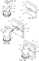
- shows the hooking element of the assembly of elements according to the invention mounted on the foot,
- Figure 14
- shows a variant of the support element for the magnet mounted and locked on the base,
- Figures 15a and 15
- bshow in sequence the union of the hooking element of to the support element with magnet of
fig. 14 , - Figure 16
- shows in front view a first variant of the support element for the magnet,
- Figure 17
- shows the support element in the same variant of
fig. 14 , - Figure 18
- shows the support element in the same variant of
fig. 14 , - Figure 19
- shows the support element in the same variant of
fig. 14 and with the magnet inserted, - Figure 20
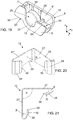
- shows a perspective view of the coupling element of the assembly of elements according to the invention,
- Figure 21
- shows it in plan
- Figure 22
- shows it in a different perspective view,
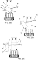
- Figures 23a-e
- show the sequence of steps to disassociate the hooking element from a foot,
- Figure 24
- shows in perspective view a further (second) variant of the support element for the magnet,
- Figure 25
- shows a plan view of the support element of
fig. 24 , - Figure 26
- shows the support element of
fig. 24 , - Figure 27
- shows in a plan view the support element of the magnet of
fig. 14 , - Figure 28
- shows the support element of
fig. 14 , - Figure 29
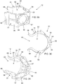
- shows in a lateral perspective view a further embodiment of the hooking element,
- Figure 30
- shows a perspective view of the hooking element of
fig. 29 , - Figure 31
- shows in a different perspective view the hooking element of
fig. 29 , - Figures 32a - 32c
- show the sequence of steps for associating/disassociating the hooking element of
fig. 29 to/from a foot, - Figure 33
- shows a perspective view of the foot with associated hooking element of
fig. 29 , - Figure 34
- shows in a plan view the foot with associated hooking element of
fig. 29 , - Figure 35
- shows in perspective view the assembly of elements according to the invention before the association of the hooking element of
fig. 29 to the support element of the magnet offig. 6 , - Figure 36
- shows in perspective view, from a different angle, the element assembly of
fig. 35 , - Figure 37
- shows in perspective view the assembly of elements according to the invention before the association of the hooking element of
fig. 29 to two different support elements offig. 6 , each of which is mounted on a respective base, - Figure 38
- shows a perspective view of the set of elements of
Fig. 37 from a different angle, - Figure 39
- shows a perspective view of the complex of elements of
Fig. 37 with the bases joined together, - Figure 40
- shows a perspective view of the set of elements of
Fig. 39 from a different angle, and - Figure 41
- shows a plan view of the complex of elements of
fig. 39 . - As can be seen from the figures, the
assembly 2, according to the invention, for joining afirst base 4 and/or a second base 4' to afoot 6 of a piece of furniture or the like, comprises a hookingelement 12, which is configured to be removably associated with thefoot 6 of the piece of furniture or the like. Conveniently, the hookingelement 12 is made at least in part of magnetic metal material, preferably ferromagnetic, or of magnetized material (ie a magnet). - The
assembly 2 further comprises afirst support element 8 for afirst magnet 10, which is configured to be magnetically connected to the hookingelement 12; suitably, thefirst support element 8 is also configured to be associated, preferably removably, with thefirst base 4. - Preferably, the
assembly 2 according to the invention further comprises a second support element 8' for asecond magnet 10', which is configured to be magnetically connected to the hookingelement 12. - Conveniently, the second support element 8' is configured to be associated, preferably removably, with the second base 4', which is intended to be positioned at an angle with respect to the
first base 4, preferably orthogonal with respect to the first base 4'. - Advantageously, the second support element 8' can be substantially congruent and interchangeable with the
first support element 8. For this reason, all the characteristics described below with particular reference to thefirst support element 8, are to be understood as described, mutatis mutandis, also for the second support element 8'. - Preferably, the assembly can also comprise a connecting
element 3 intended to be arranged in correspondence with a contact area between thefirst base 4 and the second base 4'. Preferably, according to the present invention, at least thefirst support element 8 is configured to cooperate with the connectingelement 3 to keep said connectingelement 3 associated with the first base 4'. - Preferably, in a possible embodiment not shown here, both the first and the
second support element 8, 8' are configured to cooperate with the connectingelement 3 to maintain the same connectingelement 3 associated with the respectivefirst base 4 and second base 4'. - Conveniently, the
first base 4, the second base 4' and/or thefoot 6 can be substantially of the traditional type, per se known to those skilled in the art. - Conveniently, the first and/or
second support element 8, 8' is provided with a shaped protrusion 16' configured to be inserted and then rotated, in particular by about 90°, inside achannel 14 obtained respectively in saidfirst base 4 or in said second base 4'. - Conveniently, a pair of
gripping portions second support element 8, 8' configured to allow a user to grip with the thumb and another finger of the same hand respectively, to thus facilitate the rotation of said shaped protrusion 16' of said first and/orsecond support element 8, 8' inside thechannel 14 obtained respectively in saidfirst base 4 or in said second base 4'. - Preferably, the first and/or
second support element 8, 8' is provided with abayonet coupling 16, defined by said shaped protrusion 16', to removably associate the first orsecond support element 8, 8' respectively to saidfirst base 4 or to said second base 4'. - As anticipated above, the hooking
element 12 is made at least in part of ferromagnetic material to thus allow magnetic attraction/attachment with amagnet 10 mounted (or intended to be mounted) on saidfirst support element 8, to thus allow the union/attachment of saidbase 4 to saidfoot 6. - Preferably, in a possible embodiment, the hooking
element 12 is made at least in part of ferromagnetic material to thus allow magnetic attraction/attachment with thefirst magnet 10 mounted (or intended to be mounted) on thefirst support element 8 and with thesecond magnet 10' mounted (or intended to be mounted) on the second support element 8', to thus allow the union/attachment of thefirst base 4 and of the second base 4' to thefoot 6. - Preferably, the first and/or the
second support element 8, 8' can substantially have the shape of a plate, and in particular its development in thickness is less than r compared to that of the other two dimensions. Conveniently, the first and/orsecond support element 8, 8' comprises two walls, and in particular afront wall 9, configured to face in use condition (ie when thefirst base 4 is associated with the foot 6) towards thefoot 6, and a rear wall 9' configured to face in use condition towards thefirst base 4. Saidwalls 9, 9' can be joined together by a plurality of stiffening sections, walls or and/or sections which suitably develop and define the thickness of the support element. - Advantageously, the first and/or
second support element 8, 8' can be made of polymeric materials, preferably of plastic. Conveniently, thefirst support element 8 can be made by injection molding. Alternatively, the first and/orsecond support element 8, 8' could be made of wood or a non-magnetic metal or other materials in general preferably non-magnetic. - Conveniently, the first and/or
second support element 8, 8' is provided, in correspondence with its rear wall 9', with said protrusion 16' which, advantageously, defines the bayonet-operatedcoupling 16 within thelongitudinal channel 14 obtained respectively in the first 4 or in the second base 4'. - Preferably, in correspondence with its rear wall 9', the first and/or
second support element 8, 8' is provided with said substantially hammer-shaped protrusion 16', defining thebayonet coupling 16, which is intended to be inserted into thelongitudinal channel 14 which is suitably counter-shaped with respect to said protrusion. - In particular, said
longitudinal channel 14 is longitudinally formed on at least one internal surface 17 (ie intended to be turned towards the foot 6) of thefirst base 4 and/or of the second base 4' respectively. Conveniently, thechannel 14 is defined by agroove 22 obtained on a surface of saidbase 4 and/or 4'. - Conveniently, the hammer-like protrusion 16' is defined by an
outermost part 20 which is connected to the rear wall 9' of the first and/orsecond support element 8, 8' by aneck 18. In particular, the coupling between the thefirst support element 8 and thefirst base 4 takes place according to traditional methods by inserting the protrusion 16' inside thechannel 14 so that theoutermost part 20 of the latter is initially parallel to the direction of development of thechannel 14 itself. Subsequently, thefirst support element 8 is made to rotate by about 90° - in particular it is made to rotate by about 90° around the development axis of the neck 18 - so that the hammer-like undercut portions of the protrusion 16' go into abutment on the correspondingcounter-shaped edges 24 of thechannel 14, thus preventing/blocking the extraction of thefirst support element 8 from thefirst base 4. Conveniently, the coupling of the second support element 8' and the second base 4' can occur with the same modes just described above. - Advantageously, at the rear wall 9' of the first support element 8 (and advantageously also of the second support element 8'), at least one, and preferably at least two
reliefs 21, can be provided, which are intended to cooperate with theinternal surface 17 of thefirst base 4, for the main purpose of opposing the relative sliding of thefirst support element 8 within thechannel 14, once said first element has been inserted and rotated inside said channel. - Advantageously, the two
walls 9 and 9' have different shapes and sizes. - Advantageously, the connecting
element 3 comprising a profile with twoportions 31, 31' arranged in an "L" shape in which corresponding ends of thebases 4, 4' are intended to abut frontally respectively with the first 31 and the second portion 31' of the connectingelement 3. Preferably, the twoportions 31, 31' are substantially orthogonal to each other. - Conveniently, the second portion 31' of the profiled element, the smaller one, has a folded free
longitudinal edge 35 so as to define a fin which is substantially parallel to thefirst portion 31, the greater one, of the profiled element itself. Furthermore, the other edge of the second portion 31' extends beyond thefirst portion 31 defining alongitudinal shoulder 36 which is orthogonal to the latter. - Advantageously, the profile that defines the connecting
element 3 is dimensioned so that the distance between the facing surfaces of the foldededge 35 and of thefirst portion 31 substantially corresponds to the thickness of the end of thebase 4. - Furthermore, at least the first connecting
element support 8 advantageously comprises first cooperation means 23 which are intended to cooperate, as will become clearer below, with corresponding second cooperation means 32 provided in thefirst portion 31 of the connectingelement 3 in order to oppose the relative sliding along saidfirst base 4, between thefirst support element 8 and the connectingelement 3. - Advantageously, on the side of the
longitudinal shoulder 36 and in correspondence with itsterminal portion 37, thefirst portion 31 is affected by the second cooperation means 32 which are designed to cooperate with the first means 23 of thefirst support element 8. - Conveniently, the first cooperation means 23 of the
first support element 8, which cooperate with the second cooperation means 32 of the connectingelement 3, have a surface profile substantially complementary to each other. - Preferably, these first cooperation means 23 comprise a plurality of
semicircular grooves 38, parallel to each other which, in use, are substantially vertical. - Conveniently, the first means 23 of the
first support element 8 have a surface profile complementary to that of the second means 32 of the connectingelement 3. - In accordance with the preferential embodiment of the present invention, illustrated in the attached figures, the first cooperation means 23 of the
first support element 8 which cooperate with the second cooperation means 32 are configured so as to increase the friction resulting from the contact and/or sliding between the connectingelement 3 and thefirst support element 8. Advantageously, thefirst support element 8 comprises a rear wall 9' on which the first cooperation means 23 are defined which are intended to cooperate with the second cooperation means 32 which, preferably, are formed on theterminal portion 37 of thefirst portion 31 of the section that defines the connectingelement 3. - Advantageously, the first cooperation means 23 are obtained on a face, for example on the rear face (as shown in the figures), of at least one
lateral extension 62 of the rear wall 9' of thesupport element 8. Preferably, twolateral extensions 62 are provided, to thus allow thesame support element 8 to cooperate with a connectingelement 3 positioned both to its right and to its left. In particular, thelateral extensions 62 are positioned laterally with respect to thecentral zone 61 in correspondence with which thebayonet coupling 16 is obtained/provided. Preferably, thelateral extensions 62 are offset (ie parallel and not coplanar) with respect to thecentral zone 61.
in order to allow the coupling between thesupport element 8 and the connectingelement 3, the rear wall 9' of thefirst support element 8 on which are formed the first cooperation means 23 defines a concavity and/or is slightly offset with respect to the adjacent part (for example to the central zone 61) or the remaining part of said wall, to thus delimit with the first base 4 a loop for the stable insertion of theterminal portion 37 of thefirst portion 31 of the connectingelement 3 on which the second cooperation means 32 are obtained. - Conveniently, in an embodiment not shown here, the
terminal portion 37 provided with the second cooperation means 32 can be offset with respect to the remaining part of thefirst portion 31 of the connectingelement 3 so that, once the latter has been associated with thebase 4, theterminal portion 37 delimits with the base itself a loop for the insertion of the part (ie the lateral extension 62) of the rear wall 9' of thesupport element 8 on which the first cooperation means 23 are made and which, in this case, is coplanar with the remaining part of the body of theplate 10 Furthermore, suitably, in this case, the first cooperation means 23 are obtained on the front face of the rear wall 9'. - As anticipated above, the first cooperation means 23 preferably comprise a first succession of
grooves 38 which are intended to engage in shape relationship with correspondingsecond ribs 39 of the second cooperation means 32. - Preferably, the second cooperation means 32 comprise a plurality of protruding
ribs 39, vertical and parallel to each other suitable to be inserted inside thegrooves 38 of the first cooperation means 23. - Obviously, the first and second cooperation means 23, 32 may include any type of surface finish and/or protruding and/or recessed element suitable for defining said shape ratio to thus mechanically engage the connecting
element 3 to thefirst support element 8. In particular, it is understood that the first cooperation means 23 of thefirst support element 8 which are designed to cooperate with corresponding second cooperation means 32 of the connectingelement 3 in order to control stopping the relative sliding between saidfirst element 8 and said connectingelement 3 can comprise other traditional types of interaction and/or mechanical coupling between two elements, such as for example means and counter-means for achieving a coupling by hooking, or by interlocking (for example of the male-female type), or by clamping, by interference, by coupling - even partial - of shape, etc. - Conveniently, the end of the
first base 4 is intended to abut frontally with the second portion 31' of the connectingelement 3 and to be retained laterally between a foldedlongitudinal edge 35 of the second portion 31' and thefirst portion 31 of the connectingelement 3, and the end of the second base 4' is intended to abut frontally with thefirst portion 31 of said connectingelement 3. - Advantageously, the first support element 8 (and advantageously also the second supporting element support 8') comprises a
seat 26 for saidmagnet 10. Conveniently, theseat 26 can be defined between the twowalls 9, 9' of thefirst support element 8 and, preferably, is defined within the thickness of thesupport element 8. Conveniently, theseat 26 is closed by the rear wall 9' of thefirst support element 8 while it is open at itsfront wall 9. Preferably, theseat 26 is configured for c to feel the easy, quick and removable insertion - and/or extraction - of thefirst magnet 10. - Preferably, in a possible embodiment (cf.
fig. 27 and 28 ), theseat 26 is oversized - in particular in width (see spaces 48) but could also be so in terms of thickness - compared to thefirst magnet 10. Conveniently, for this purpose, the stable housing of thefirst magnet 10 inside theseat 26 it is made by suitable filling or adhesive means. Advantageously, in this way, magnets of different sizes and/or shapes can be inserted and housed within theseat 26. - Preferably, in another possible embodiment, the
seat 26 can be configured to prevent the movement of themagnet 10 with respect to two directions which are perpendicular to each other and are also perpendicular to the direction of insertion/extraction of themagnet 10 within theseat 26. - Conveniently, the
seat 26 can be delimited by the rear wall 9', by acontainment edge 25 obtained in correspondence with thefront wall 9 and bylateral connecting walls 11 which are interposed between said two faces and which extend substantially perpendicularly between these. Advantageously, the front/external face of themagnet 10 is partially retained by thecontainment edge 25 even though it is for the most part free and/or uncovered, to thus allow its magnetic coupling with the hookingelement 12, as will be clearer in following. - Conveniently, the
seat 26 can have a conformation which substantially corresponds - at least in part - to that of thefirst magnet 10. Advantageously, theseat 26 can comprise, on the surface of the rear wall 9' which is intended to face towards themagnet 10, ribs 26' which are intended to cooperate with the rear/internal face of themagnet 10 in order to prevent the extraction of themagnet 10 once it has been inserted into said seat. Advantageously, in thezone 49 defined between the ribs 26' a suitable filler or adhesive can be inserted inside theseat 26, to thus allow the stable locking of thefirst magnet 10 within said seat. - Conveniently, the seat 26 - in addition to being open in correspondence with the
front wall 9 which is intended to face thefoot 6 to be associated with the base 4 - is also open in the direction of insertion/removal of thefirst magnet 10 in/from the seat itself. - Advantageously, the
first magnet 10 is substantially a magnet. Conveniently, thefirst magnet 10 has a disk or cylindrical shape, but it could also have the shape of a prism with a polygonal base or a truncated or truncated pyramid shape. Correspondingly, theseat 26 defined in thefirst support element 8 can be shaped to allow a stable positioning of themagnet 10 which is mounted/supported in/by said element. Conveniently, themagnet 10 is configured to generate a magnetic field suitable for allowing a stable coupling of thefirst base 4 to thefoot 6, while allowing its easy removal, as will become clear later. - The first support element 8 (and preferably also the second support element 8') comprises at least a pair of
gripping portions first support element 8 in order to activate saidbayonet coupling 16, once said coupling has been suitably and previously inserted into thechannel 14 of thebase 4. - Advantageously, the gripping
portions first support element 8 and are offset from each other in height, thus making the grip of thesupport element 8 particularly ergonomic in order to cause its locking rotation. - Conveniently, said gripping
portions support element 8 so that one grippingportion 33 receives the user's thumb in support, while the other grippingportion 33' receives in support another finger (and in particular the index or middle finger) of the same hand of said user. Advantageously, this arrangement facilitates gripping and rotation of thesupport element 8 around the axis of rotation which crosses the protrusion 16'. - Conveniently, said gripping
portions support element 8 in diametrically opposite positions with respect to the center of gravity of the support element itself, which substantially corresponds to the point crossed by the axis around which saidsupport element 8 wheel. In particular, the twogripping portions support element 8 in diametrically opposite positions with respect to the protrusion 16', and in particular with respect to the point where theneck 18 of the protrusion 16' connects to the rear wall 9' of thesupport element 8. - Advantageously, the gripping
portions support element 8 in diametrically opposite positions with respect to themagnet 10. - Preferably, said gripping
portions support element 8. In particular, a first groove - which defines the first gripping portion 33 - can be obtained on thefront wall 9 of thesupport element 8, while a second recess - which defines the other grippingportion 33' - is formed on bothwalls 9, 9' of the support element. - Conveniently, in correspondence with said recesses,
transverse walls 19 can be provided to define a support, advantageously wider - for the corresponding finger of the user. - Conveniently, in a first possible embodiment (see
fig. 20 - 22 ), the hookingelement 12 substantially comprises a fork hook configured to detachably embrace/engage theshaft 13 of thefoot 6. In particular, this hookingelement 12 comprises twoarms 27, 27' angled to each other, which surround and elastically and partially embrace theshaft 13 of thefoot 6. Preferably, thearms 27, 27' are directly connected to each other so as to confer on the hookingelement 12 an overall "L" or "V" shape, preferably with two sections of the same length. In particular, thearms 27, 27' define an angle α between them, preferably having an amplitude substantially equal to or less than about 90°. - Conveniently, the two
arms 27, 27' have a laminar conformation. Conveniently, the twoarms 27, 27' have substantially the same length, which for example can be slightly greater than the diameter of theshaft 13 of thefoot 6 to which the hookingelement 12 is intended to be hooked. Preferably, the joint/bend between the twoarms 27, 27' can be angled or, preferably, it can be slightly rounded. - Advantageously, the hooking
element 12 is made - preferably entirely - of magnetic metal material, and preferably of ferromagnetic material, and in particular it can be made of iron. Conveniently, the twoarms 27, 27' are made at least in part - preferably entirely - in magnetic metallic material, preferably in ferromagnetic material. Conveniently, at least the outer surface of the twoarms 27, 27' is made of magnetic metal material, preferably of ferromagnetic material. - Advantageously, said hooking
element 12 can be made of folded sheet of magnetic metal, preferably ferromagnetic. Preferably, the hookingelement 12 is defined entirely and only by a single folded sheet of a magnetic metal. - Advantageously, the two
arms 27 of the hookingelement 12 can be made of polymeric material and, in this case, said hookingelement 12 can comprise plates of magnetic metal material, and preferably of ferromagnetic material, which are fixed (for example by means of bonding) to the external surfaces of said twoarms 27. - Conveniently, the hooking
element 12 is configured in such a way as to allow an elastic variation of the mutual distance between the twoarms 27, 27', in particular to allow them to surround and then embrace/hook theshaft 17 of thefoot 6. Conveniently, for this purpose, one or both of thearms 27, 27' are elastic, at least in correspondence with the fold for their connection. - Conveniently, the hooking
element 12 is configured so that, once theshaft 13 of thefoot 6 has been embraced, it can then be translated vertically - maintaining said embrace - along the height of the foot itself. - Conveniently, one or both of the
arms 27, 27' have a greater length, preferably much greater, than the dimensions of themagnet 10 mounted in theseat 26 of thesupport element 8, thus allowing to correct, even after joining thebase 4 to thefoot 6, a possible positioning error simply by translating the base to the right or left, since the magnetic link between themagnet 10 mounted on thesupport element 8, in turn mounted on thebase 4, remains active for the entire length development of thearms 27, 27' of the hookingelement 12 mounted on thefoot 6. - Advantageously, at least one of the two
arms 27, 27' has at least one of the two edges with a profile shaped so as to define a section hollowed inwards in correspondence and/or proximity of the connecting bend between said two arms. - Conveniently, the recessed
portion 29 is formed in such a way that the width of thearm 27 and/or 27', in correspondence with and/or near the end of connection with the other arm, is smaller than the width of the arm itself at the free end. - Advantageously, in this way, when the hooking
element 12 is applied and embraces/engages thefoot 6, it is possible to insert - preferably from top to bottom - a tool 52 (for example an Allen key or a screwdriver) into the space between the foot itself and thearm 27 and/or 27', to make it then come out at the edge provided with the recessedportions 29. - Advantageously, at each free end of the
arms 27, 27' of the hookingelement 12,curved portions 28 and 28' are provided, which are substantially folded backwards and inwards. Conveniently, said bending can form an acute angle with thecorresponding arm 27, 27' of the hookingelement 12. - Preferably, furthermore, the
curved portions 28 and 28' each terminate with one of the further curved portions, respectively 30 and 30'. In particular, said further curvedportions 30, 30', which with the respectivecurved portions 28, 28' define an obtuse angle and which are configured to abut against theshaft 17 of thefoot 6. - Conveniently, the bends at the corner between the two
arms 27, 27' and/or at the angles between eacharm 27, 27' and the correspondingcurved section 28, 28' and/or at the angles Ω between eachcurved section 28, 28' and the corresponding furthercurved section 30, 30' give the hooking element 12 a suitable elasticity to allow it to deform so as to stably surround, embrace and hook thefoot 6. - Conveniently, in another possible and preferred embodiment illustrated in
figures 29 - 41 , the hookingelement 12 comprises: - a
fork hook 50, made of polymeric material, which is configured to removably engage theshaft 13 of thefoot 6, - at least one
body 60 in magnetic metal material, preferably in ferromagnetic material, which is fixed to or incorporated in saidfork hook 50, for the magnetic connection with themagnet support element 8 or 8'. - In particular, this
fork hook 50 comprises twoelastic fins 51 which surround and externally embrace, at least in part, theshaft 13 of thefoot 6. Preferably, theelastic fins 51 are shaped in such a way as to delimit afirst area 52, intended to engage and embrace the shaft of said foot, and a second flaredarea 53 adapted to favor said engagement. Preferably, theelastic fins 51 are shaped and joined together so as to externally embrace thefoot 6, in particular by coming into contact with the surface of theshaft 13 of the foot itself, for a greater extension with respect to the semicircumference of said shaft. Conveniently, thefork hook 50 is configured so that, when the hookingelement 12 is associated with theshaft 13 of thefoot 6, the internal surface of theelastic fins 51 and of their connectingportion 55 wraps around and is in contact with several half of the circumference of theshaft 13 of thefoot 6. In substance, thefirst area 52 of thefork hook 50 wraps more than half of the circumferential extension of the stem of thefoot 6. - Furthermore, also the connecting
portion 55 between thefins 51 is curved and, preferably, has the same radius of curvature as therespective parts 56 of thefins 51 which define thefirst area 52. Conveniently, the connectingportion 55 between thefins 51 is also configured to come into contact with theshaft 13 of the foot, in particular so that the latter is continuously wound between the twoparts 56 which define thefirst area 52 and the connectingportion 55 interposed between said two parts. - In particular, the
fork hook 50 is made of thermoplastic polymeric material. - Preferably, in correspondence with the external surface (ie the opposite surface with respect to that which comes into contact with the
shaft 13 of the foot 6) of theelastic fins 51 and/or their connectingportion 55, thefork hook 50 can comprise at least oneportion 54 on which thebody 60 in magnetic metal material is fixed or incorporated. Conveniently, thebody 60 is fixed or incorporated in a correspondingportion 54 of thefork hook 50 so that the external surface remains visible at least in part or preferably for the most part, to thus allow the magnetic connection of saidbody 60 with themagnet support element 8 or 8'. - Advantageously, each
portion 54 is defined by a flat wall which is formed in a single body with theelastic fins 51 or with the connectingportion 55 interposed between them. - Conveniently, in the embodiment shown, a corresponding
portion 54 is provided on eachelastic fin 51 and, therefore, thefork hook 50 comprises twoportions 54 which are angled to each other, and preferably are orthogonal to each other. - Conveniently, in a possible variant embodiment not shown here, the
fork hook 50 can be provided with asingle portion 54 which is obtained substantially in a facing position with respect to the flaredarea 53 which is defined between the free ends 58 of theelastic fins 51. - Conveniently, said
body 60 made of magnetic metal material has a laminar conformation (ie the thickness is lower, in particular much lower, with respect to the other two dimensions) and, preferably, it is a washer or disk. - Advantageously, the
body 60 in magnetic metal material is co-molded or over-molded with thefork hook 50. In particular, thebody 60 in magnetic metal material is incorporated in thefork hook 50 directly during the molding phase, thus obtaining the union and the bonding between these two components of different material. - Advantageously, the hooking
element 12 also comprises a further mechanical locking/fixing means 57 of thebody 60 to thefork hook 50, to thus better guarantee the tightness of the union of thebody 60 to thefork hook 50. Preferably, this further locking means 57 is shaped like a crown which is fixed to thefork hook 50 and which protrudes radially so as to act on a part of the external face of thebody 60. Preferably, this further locking means 57 is also made of polymeric material and is made by overmoulding with thefork hook 50 and thebody 60. - Conveniently, when the hooking
element 12 is brought close to thefoot 6, by applying an appropriate pressure, theelastic fins 51 of thehook 50 are elastically deformed to allow them to embrace and wind the corresponding foot 6 (seefig. 32a - 32c ). In particular, in this way, theshaft 13 of thefoot 6 enters thefirst area 52 of thefork hook 50, an area which is delimited by theparts 56 of theelastic fins 51 and by the connectingportion 55 interposed between said fins. - The present invention also relates to a
support element 8, 8' to be used for joining at least onebase 4, 4' to afoot 6 of a piece of furniture or the like, in particular intended to form part of a set of elements of the fin type described here and of which the same numerical references will be kept for simplicity of explanation. - The support element according to the invention is configured to support a
magnet element 12 which is associated with theaforementioned foot 6. - Furthermore, the
support element 8, 8' is configured to be associated with saidbase 4, 4' and to be connected to a connectingelement 3 intended to be arranged in correspondence with a contact area between afirst base 4 and a second base 4'. - Advantageously, in the variant of
figs. 6 and 7 , as well as in the variant offigs. 16-19 , thesupport element 8 is configured to be removably associated with thebase 4 and, preferably, for this purpose, is provided with saidbayonet coupling 16. - Advantageously, in a further variant of the
support element 8, such as the one represented infigs. 24-26 , thesupport element 8 is configured to be associated with thebase 4 by means of dedicated fastening members, and in particular by means of screws. Conveniently, this variant of thesupport element 8 is suitable for use withbase 4 made of chipboard or similar materials. In particular, in this embodiment variant, nobayonet coupling 16 or other rear protrusion is provided on the rear wall, while throughholes 65 are provided in correspondence with the rear wall 9' for passing through fastening members (such as for example self-tapping screws, not shown) of thesupport element 8 to thebase 4. - Advantageously, the
support element 8, 8' can comprise first cooperation means 23 which are configured to cooperate with second cooperation means 32 provided in thefirst portion 31 of said connectingelement 3 in order to oppose the relative sliding - along thebase 4, 4' to which the support element is associated - between thesame support element 8, 8' and said connectingelement 3 and/or to maintain said connectingelement 3 associated with saidbase 4. - More in detail, preferably, the
support element 8, 8' comprises a rear wall 9' on which are defined first cooperation means 23 which are intended to cooperate with second cooperation means 32 obtained on afirst portion 31 of a profile which defines the connectingelement 3. - Preferably, said
support element 8, 8' is provided with abayonet coupling 16 to associate the support element with thebase 4. - Advantageously, moreover, on said
support element 8, 8' are defined a pair ofgripping portions support element 8, 8' in order to activate said bayonet coupling. Preferably, said grippingportions support element 8, 8' and are offset from each other in height, thus making gripping of thesupport element 8, 8' particularly ergonomic in order to cause its rotation for the activation of the bayonet coupling. - Advantageously, said gripping
portions support element 8, 8' so that one grippingportion 33 rests on the thumb finger of the user's hand, while the other grippingportion 33' receives in support the index or middle finger of the same hand of said user. Preferably, said grippingportions support element 8, 8' in diametrically opposite positions with respect to the center of gravity of the support element itself. Preferably, said grippingportions support element 8, 8' in diametrically opposite positions with respect to the point crossed by the axis around which saidsupport element 8, 8' rotates, once it has been mounted on saidbase 4. - Advantageously, said
support element 8, 8' is made of polymeric materials, preferably plastic, or other non-magnetic material. - Advantageously, said
support element 8, 8' comprises a plate with afront wall 9, intended to be turned towards thefoot 6 in use, and a rear wall 9' intended to be turned towards saidbase 4 when in use condition. - Advantageously, said
support element 8, 8' comprises aseat 26 for saidmagnet 10, and said seat is defined between the twowalls 9, 9' of thesupport element 8, 8' and inside the thickness of saidsupport element 8, 8', saidseat 26 being closed by the rear wall 9' of thesupport element 8 while it is open at itsfront wall 9. - Preferably, in a possible embodiment (see
fig. 27 and 28 ), theseat 26 is oversized - in particular in width (see spaces 48) but could also be so in terms of thickness - compared to thefirst magnet 10. Conveniently, for this purpose, the stable housing of thefirst magnet 10 within theseat 26 is realized by means of suitable filling or adhesive means. Advantageously, in this way, magnets of different sizes and/or shapes can be inserted and housed within theseat 26. - Advantageously, in a possible and preferred embodiment, said
support element 8, 8' is configured so that theseat 26 for saidmagnet 10 substantially prevents themagnet 10 from moving with respect to two directions Y, Z which are perpendicular to each other and also they are both perpendicular to the direction X of insertion/extraction of the magnet within saidseat 26. - Advantageously, said gripping
portions support element 8 in diametrically opposite positions with respect to aseat 26, defined in saidsupport element 8, for the insertion and housing of saidmagnet 10. - Advantageously, said gripping
portions recesses front wall 9 of saidsupport element 8, 8'. Preferably, said grippingportions recesses walls 9, 9' of saidsupport element 8, 8'. - Advantageously, said
support element 8, 8' comprises afirst recess 34 which defines the first grippingportion 33 which is obtained only on thefront wall 9 of thesupport element 8, while asecond recess 34' which defines the other grippingportion 33' is obtained on bothwalls 9, 9' of thesupport element 8. Preferably, in correspondence with saidrecesses transverse walls 19 are provided, formed between thefront wall 9 and the rear wall 9' of saidsupport element 8, 8', to thus define a wider support for the corresponding finger of the user's hand. - Advantageously, said two walls of the
support element 8, 8' have different shapes and dimensions. Preferably, saidrecess portion front wall 9, while the corresponding area of the rear wall 9', which faces saidrecess - A method for assembling the assembly and the support element described up to now, both of which are the object of the present invention, is also described below.
- The mode of operation of the
assembly 2 of elements for joining the bases of a piece of furniture or the like is clear from the description of the same. - In particular, first the first support element 8 - with the
magnet 10 already inserted in the seat 26 - is applied to thefirst base 4, appropriately inserting the protrusion 16' into thelongitudinal channel 14 obtained in the base itself. Subsequently, thesupport element 8 is made to slide along the channel of thebase 4 so as to distance it from the end of the latter and thus bring it approximately (ie "by eye" and with a good margin of tolerance) in the desired position, which is suitably aligned/facing thefoot 6 of the piece of furniture to which thefirst base 4 is intended to be joined. Then, once the desired position has been approximately reached, the user places the thumb finger of the hand on a grippingportion 33 of thefirst support element 8 and another finger of the same hand on the other grippingportion 33' to rotate thus thesupport element 8 easily by 90° inside thechannel 14 of thebase 4. In essence, the configuration and arrangement of thegripping portions support element 8 facilitates the activation of thebayonet coupling 16 of saidsupport element 8 on thebase 4, to thus associate thesupport element 8 with thebase 4. - Conveniently, it is understood that the
magnet 10 can be inserted in theseat 26 of thesupport element 8 before or after the assembly and/or locking of the latter on thebase 4. - Advantageously, the above operating steps are to be repeated identically, mutatis mutandis, to connect the second support element 8' to the second base 4'.
- Before or after the aforesaid operation carried out on the
base 4, the hookingelement 12 is applied to thefoot 6. In particular, by applying an appropriate pressure, thearms 27, 27' or thefins 51 of the hookingelement 12 are elastically deformed to allow them to be hooked to thecorresponding foot 6. - Conveniently, the hooking
element 12 is applied to thefoot 6, and/or subsequently rotated with respect to this, so that the external face of at least one of the twoarms 27, 27' or theportion 54 with thebody 60 of at least one of theelastic fins 51 of said element faces, oriented and substantially parallel to the correspondingfirst base 4 or second base 4' to be joined. In the case in question, the foot is of the angled type and the twoarms 27, 27' or the twoportions 54 with theirrespective bodies 60 are advantageously angled to each other in order to be both parallel and to twobases 4, 4' which will be associated with two corresponding and distinct sides of the cabinet. - Then, the
base 4 thus prepared is brought close to the hookingelement 12 so that the magnetic attraction between themagnet 10, which is mounted in thesupport element 8 fixed to thebase 4, and thearm 27 or 27' of the hookingelement 12 in magnetic metal, preferably ferromagnetic, which is coupled to thefoot 6, thus allows to attach/join the socket to said foot, and also to maintain this union/attachment stably. Advantageously, themagnet 10 of thesupport element 8 mounted on thebase 4 is attracted by thearm 27 or 27' of the hookingelement 12 along the entire extension of the corresponding arm, and therefore a particularly accurate and precise positioning of the thesupport element 8 itself along thebase 4. - Conveniently, using the hooking
element 12 of the embodiment illustrated infigures 32a and following, the previouslyprepared base 4 is brought close to the hookingelement 12 so that the attraction between themagnet 10, which is mounted in thesupport element 8 fixed to thebase 4, and themagnetic metal body 60, preferably ferromagnetic, which is incorporated in thefork hook 50 of the hookingelement 12 associated with thefoot 6, thus allows to attach/join the socket to said foot, and also to maintain this union/attachment stably. Advantageously, themagnet 10 of thesupport element 8 mounted on thebase 4 is attracted to thebody 60 incorporated in the hookingelement 12. - It is conveniently understood that the
fork hook 50 of the hookingelement 12 can be fixed/glued or incorporated even asingle body 60 in magnetic metal, preferably ferromagnetic, for example to associate a central and intermediate (ie not extremal) portion of thebase 4 with thefoot 6. - Subsequently, the connecting
element 3 is applied in correspondence with a joining area between the first andsecond base 4, 4', in particular on the end of thefirst base 4 so that the leadingedge 42 strikes frontally with the base of the second portion 31', while it is held laterally between the longitudinal foldededge 35 and thefirst portion 31. - Subsequently, the
first support element 8 is made to slide towards the connectingelement 3, until the rear wall 9' of the first andsupport element 8 intercepts theterminal portion 37 of thefirst portion 31 of the connectingelement 3. In particular, in doing so, the first cooperation means 23 and the second cooperation means 32 interact with each other, regulating the positioning of the firstconnection element support 8 on the connectingelement 3 and blocking any possible involuntary sliding of thefirst support element 8 with respect to the connectingelement 3. - Advantageously, the fact that the first cooperation means 23 and the second cooperation means 32 consist of
grooves 38 and byvertical ribs 39, it allows to adjust for successive clicks the sliding of thefirst element 6 on thesecond element 8. - Conveniently, it is understood that the second base 4' intended to define the junction (i.e. the one to which the first support element is not bound 8 and the connecting element 3) can be associated/constrained to the
furniture foot 6 by means of a corresponding (second) support element or 8' which has the same constructive and functional characteristics as thefirst support element 8 of theassembly 2, or by means of any other traditional coupling element or device. - Conveniently, it is understood that, according to a further variant of the present invention, in the
support element 8 or 8', instead of themagnet element 12, preferably in place of thebody 60 described above. - The set of
elements 2 according to the invention is particularly advantageous with respect to the traditional ones in that: - allows a simple and quick assembly and locking of the support elements to the respective bases and at the same time allows a quick and simple connection to a connecting element,
- it can also be used with bases that are made/cut in an imprecise way since it is sufficient for their leading edge to lean frontally (i.e. without the need for any insertion) on the connecting element, hiding any imperfections
- the adjustment during assembly is extremely simple since it only requires sliding the first support element with respect to the connecting element so that the connecting means are aligned with the foot to which both the junction bases must be constrained;
- in particular, the simplicity of assembly reduces the intervention times of the professional installer, at the time of the first installation, as well as facilitates the interventions of temporary removal and subsequent reapplication of the bases which are generally carried out by the user in order to access, for example to carry out cleaning, to the space enclosed between the hooves themselves,
- it is not necessary that the support element be mounted in a particularly precise and accurate way and furthermore, the ergonomic shape of the support element facilitates the locking rotation of the same element on the base,
- allows you to correct any positioning errors simply by moving the base sideways, without detaching it from the foot,
- it allows a simple and quick association of the base to the piece of furniture; in particular, once the support element and the coupling element have been mounted respectively on the base and on the foot, it is sufficient to bring the base to the furniture foot,
- it is economical since it consists of a small number of components that can easily be mass-produced.
- The present invention has been illustrated in some of its preferred embodiments, but it is understood that executive variations may be made in practice, without however departing from the scope of protection of the present patent for industrial invention.
Claims (15)
- Set (2) of improved elements for joining at least one base (4, 4') to the foot (6) of a piece of furniture or the like, characterized in that it comprises:- at least one support element (8, 8') for a magnet (10, 10'), or for a magnetic metal part, preferably ferromagnetic, said at least one support element (8, 8') being configured to be removably associated with said base (4, 4'), said at least one support element (8, 8') being provided with a shaped protrusion (16') configured to be inserted and then rotated inside a channel (14) obtained in said base (4, 4'),- a hooking element (12) which is configured to be removably associated with said foot (6) of said piece of furniture, or the like, so as to hook onto the shaft (17) of said foot (6), said hooking element (12) comprising at least a part (27, 27', 60) in magnetic metal material, preferably ferromagnetic, or a magnet, to allow the magnetic connection with said magnet (10), or with said magnetic metal part, which is mounted on said at least one support element (8, 8'), and thus allowing the union of said base (4, 4') to said foot (6),and also characterized by the fact that:- on said at least one support element (8, 8') there are defined a pair of gripping portions (33, 33') configured to allow gripping by a user respectively with the thumb and another finger of the same hand, in order to facilitate the rotation of said shaped protrusion (16') of said at least one support element (8, 8') inside the channel (14) obtained in said base (4, 4').
- Assembly (2) of elements according to claim 1 for joining at least a first base (4) and a second base (4') to a foot (6) of a piece of furniture or the like, characterized in that said at least one support element (8, 8') comprises first cooperation means (23) configured to cooperate with corresponding second cooperation means (32) provided in a connecting element (3) which is intended to be arranged in correspondence with an area of contact between said first base (4) and said second base (4').
- Set of elements according to one or more of the preceding claims, to be used for joining at least a first base (4) and a second base (4') to a foot (6) of a piece of furniture or the like, characterized in that it comprises:- said hooking element (12),- a first support element (8) for a first magnet (10), or for a magnetic metal part, preferably ferromagnetic, which is configured to be magnetically connected to said hooking element (12), said first support element (8) being configured to be associated with said first base (4),- a second support element (8') for a second magnet (10'), or for a magnetic metal part, preferably ferromagnetic, which is configured to be magnetically connected to the same hooking element (12) to which it is intended to be magnetically connected to said first support element (8), said second support element (8') being configured to be associated with said second base (4') intended to be positioned at an angle with respect to said first base (4), preferably orthogonal with respect to said first base (4');- a connecting element (3) intended to be arranged in correspondence with a contact area between said first base (4) and said second base (4'),and also characterized in that said first support element (8) and/or said second support element (8') comprises first cooperation means (23) configured to cooperate with corresponding second cooperation means (32) provided in said connecting element (3).
- Complex according to claims 2 or 3, characterized in that:- said connecting element (3) comprises a section with two portions (31, 31') arranged in an "L" shape in which corresponding ends of said bases (4, 4') are intended to abut frontally respectively with said first and said second portion of said connecting element (3);- said first cooperation means (23) are configured to cooperate with said second cooperation means (32) provided in the first portion (31) of said connecting element (3) in order to oppose relative sliding along said first base (4), between said first support element (8) and said connecting element (3) and/or to keep said connecting element (3) associated with said first base (4).
- Assembly according to one or more of claims 2-4, characterized in that the first cooperation means (23) of said first support element (8) and/or second support element (8'), which cooperate with the second cooperation means (32) of said connecting element (3) have a surface profile substantially complementary to each other.
- Assembly according to one or more of claims 2-5, characterized in that said first support element (8) and/or said second support element (8') comprises a rear wall (9') on which said first cooperation means (23) which are configured to cooperate with said second cooperation means (32) obtained on the terminal portion (34) of a first portion (31) of said section which defines said connecting element (3).
- Complex according to one or more of claims 2-6, characterized in that:- the rear wall (9') of said first support element (8) and/or second support element (8') on which said first cooperation means (23) are formed is configured to define with said first base (4) a loop for the stable insertion of the terminal portion (34) of said first portion (31) of said connecting element (3) on which said second cooperation means (32) are formed, or- the portion (33) of the first portion (31) of said connecting element (3) provided with the second cooperation means (32) is configured to define with said first base (4) a loop for the stable insertion of the area of the rear wall (9') of said first support element (8) and/or second support element (8') on which said first cooperation means (23) are made.
- Assembly according to one or more of claims 4-7, characterized in that the end of said first base (4) is intended to abut frontally with said second portion (31') of said connecting element (3) and to be retained laterally between a longitudinal folded edge (35) of the second first portion (31') and said second portion (30) of said connecting element (3), and the end of said second base (4') being designed to abut frontally with said first portion (31) of said connecting element (3).
- Set of elements according to one or more of the preceding claims, characterized in that said gripping portions (33, 33') are defined respectively on opposite sides of said at least one support element (8, 8') and are staggered in height, thus making the grip of said support element (8, 8') particularly ergonomic in order to cause the rotation of the shaped protrusion (16') obtained on the rear wall (9') of said support element (8, 8').
- Assembly of elements according to one or more of the preceding claims, characterized in that said at least one support element (8, 8') comprises a plate with a front wall (9), intended to be turned towards the foot (6), and a rear wall (9') intended to be turned towards said base (4, 4') when in use and by the fact that:- said two walls (9, 9') of the same support element (8, 8') have different shapes and/or dimensions,- said gripping portions (33, 33') are obtained by means of recesses (34, 34') made on one or both of said walls (9, 9') of said support element (8, 8').
- Assembly of elements according to one or more of the preceding claims, characterized in that said gripping portions (33, 33') are defined on said at least one support element (8, 8') in diametrically opposite positions with respect to the point crossed from the axis around which said support element (8, 8') rotates, once said shaped protrusion (16') has been inserted into the channel (14) obtained on said base (4, 4'), and also diametrically opposite with respect to a seat (26), defined in said support element (8), for the insertion and housing of said magnet (10), or of said magnetic metal body, preferably ferromagnetic.
- An assembly of elements according to one or more of the preceding claims, characterized in that the hooking element (12) comprises two arms (27, 27') angled between them, that surround and embrace at least partially elastically and the shaft (13) foot (6), said arms (27, 27') being directly connected to each other so as to give the hooking element (12) an overall "L" or "V" shape.
- Assembly of elements according to one or more of the preceding claims, characterized in that said hooking element (12) is made entirely and only of folded sheet of ferromagnetic metal, preferably ferromagnetic.
- An assembly of elements according to one or more of the preceding claims, characterized in that said hooking element (12) comprises:- a fork hook (50) which is made of polymeric material and which is configured to removably engage the shaft (13) of the foot (6),- at least one body (60) in magnetic metal material, preferably in ferromagnetic material, or a magnetized body, which is fixed or incorporated in said fork hook (50), for the magnetic connection with the magnet (10, 10'), or with the part in magnetic metal material, of the support element (8, 8').
- Assembly of elements according to the preceding claim, characterized in that said body (60) is co-molded or over-molded with the fork hook (50), to thus obtain their fixing.
Applications Claiming Priority (2)
| Application Number | Priority Date | Filing Date | Title |
|---|---|---|---|
| IT202020000002053U IT202000002053U1 (en) | 2020-04-30 | 2020-04-30 | Complex of elements perfected for joining a plinth to the foot of a piece of furniture or the like |
| IT102020000022456A IT202000022456A1 (en) | 2020-09-23 | 2020-09-23 | COMPLEX OF ELEMENTS IMPROVED FOR THE JOINT OF A PLINTH TO THE FOOT OF A FURNITURE OR SIMILAR |
Publications (1)
| Publication Number | Publication Date |
|---|---|
| EP3903638A1 true EP3903638A1 (en) | 2021-11-03 |
Family
ID=77908214
Family Applications (1)
| Application Number | Title | Priority Date | Filing Date |
|---|---|---|---|
| EP21171143.7A Withdrawn EP3903638A1 (en) | 2020-04-30 | 2021-04-29 | Set of elements perfected for joining a plinth to the foot of a piece of furniture or the like |
Country Status (1)
| Country | Link |
|---|---|
| EP (1) | EP3903638A1 (en) |
Cited By (1)
| Publication number | Priority date | Publication date | Assignee | Title |
|---|---|---|---|---|
| EP4762995A1 (en) | 2024-12-20 | 2026-06-24 | Volpato Industrie S.p.A. | Improved system for joining skirting boards to the foot of a piece of furniture or similar |
Citations (2)
| Publication number | Priority date | Publication date | Assignee | Title |
|---|---|---|---|---|
| EP3335595A1 (en) * | 2016-12-14 | 2018-06-20 | Volpato Industrie S.p.A. | Group of improved elements for joining the plinths of a piece of furniture or the like |
| EP3616565A1 (en) * | 2018-08-29 | 2020-03-04 | SCILM S.p.A. | A hooking system for compensating panels and method for installing compensating panels |
-
2021
- 2021-04-29 EP EP21171143.7A patent/EP3903638A1/en not_active Withdrawn
Patent Citations (2)
| Publication number | Priority date | Publication date | Assignee | Title |
|---|---|---|---|---|
| EP3335595A1 (en) * | 2016-12-14 | 2018-06-20 | Volpato Industrie S.p.A. | Group of improved elements for joining the plinths of a piece of furniture or the like |
| EP3616565A1 (en) * | 2018-08-29 | 2020-03-04 | SCILM S.p.A. | A hooking system for compensating panels and method for installing compensating panels |
Cited By (1)
| Publication number | Priority date | Publication date | Assignee | Title |
|---|---|---|---|---|
| EP4762995A1 (en) | 2024-12-20 | 2026-06-24 | Volpato Industrie S.p.A. | Improved system for joining skirting boards to the foot of a piece of furniture or similar |
Similar Documents
| Publication | Publication Date | Title |
|---|---|---|
| US9488204B2 (en) | Joiner for modular furniture | |
| US5855073A (en) | Workpiece positioning tool and method using same | |
| EP3344095B1 (en) | Hanging member | |
| CN204591891U (en) | Connecting device | |
| US4025216A (en) | Knockdown interlocking connectors | |
| CA2844606C (en) | Pipe holder and support | |
| US10575663B2 (en) | Wall hanging bracket | |
| US6079803A (en) | Closet organization system and method for installing same | |
| US4724572A (en) | Modular trowel | |
| RU2512872C2 (en) | Fittings | |
| KR101512487B1 (en) | Assembling tool for furniture | |
| US4658968A (en) | Adjustable bracket assembly for supporting a shelf | |
| US11118617B1 (en) | Table leg attachment | |
| GB1567685A (en) | Furniture connectors | |
| US6634511B2 (en) | Modular shelving system and components | |
| US20210008462A1 (en) | Play structure and play structure assembly methods | |
| US7717376B2 (en) | Bracket devices and systems | |
| EP3335595A1 (en) | Group of improved elements for joining the plinths of a piece of furniture or the like | |
| US4982517A (en) | Snap-together picture frame | |
| US3401652A (en) | Cabinet assembly | |
| AU769401B2 (en) | Improvements relating to fasteners | |
| WO1990011456A1 (en) | Fittings | |
| IT202000022456A1 (en) | COMPLEX OF ELEMENTS IMPROVED FOR THE JOINT OF A PLINTH TO THE FOOT OF A FURNITURE OR SIMILAR | |
| KR20120012714A (en) | Furniture assembly | |
| KR20170021181A (en) | joint for profile and 3dimensional printer using the same |
Legal Events
| Date | Code | Title | Description |
|---|---|---|---|
| PUAI | Public reference made under article 153(3) epc to a published international application that has entered the european phase |
Free format text: ORIGINAL CODE: 0009012 |
|
| STAA | Information on the status of an ep patent application or granted ep patent |
Free format text: STATUS: THE APPLICATION HAS BEEN PUBLISHED |
|
| AK | Designated contracting states |
Kind code of ref document: A1 Designated state(s): AL AT BE BG CH CY CZ DE DK EE ES FI FR GB GR HR HU IE IS IT LI LT LU LV MC MK MT NL NO PL PT RO RS SE SI SK SM TR |
|
| B565 | Issuance of search results under rule 164(2) epc |
Effective date: 20210924 |
|
| STAA | Information on the status of an ep patent application or granted ep patent |
Free format text: STATUS: THE APPLICATION IS DEEMED TO BE WITHDRAWN |
|
| 18D | Application deemed to be withdrawn |
Effective date: 20220504 |
|
| 110E | Request filed for conversion into a national patent application [according to art. 135 epc] |
Effective date: 20220627 |