EP3903553A1 - Work vehicle - Google Patents
Work vehicle Download PDFInfo
- Publication number
- EP3903553A1 EP3903553A1 EP19903108.9A EP19903108A EP3903553A1 EP 3903553 A1 EP3903553 A1 EP 3903553A1 EP 19903108 A EP19903108 A EP 19903108A EP 3903553 A1 EP3903553 A1 EP 3903553A1
- Authority
- EP
- European Patent Office
- Prior art keywords
- traveling
- working
- vehicle
- threshold
- controller
- Prior art date
- Legal status (The legal status is an assumption and is not a legal conclusion. Google has not performed a legal analysis and makes no representation as to the accuracy of the status listed.)
- Pending
Links
Images



Classifications
-
- G—PHYSICS
- G05—CONTROLLING; REGULATING
- G05D—SYSTEMS FOR CONTROLLING OR REGULATING NON-ELECTRIC VARIABLES
- G05D1/00—Control of position, course, altitude or attitude of land, water, air or space vehicles, e.g. using automatic pilots
- G05D1/02—Control of position or course in two dimensions
- G05D1/021—Control of position or course in two dimensions specially adapted to land vehicles
- G05D1/0287—Control of position or course in two dimensions specially adapted to land vehicles involving a plurality of land vehicles, e.g. fleet or convoy travelling
- G05D1/0291—Fleet control
- G05D1/0295—Fleet control by at least one leading vehicle of the fleet
-
- G—PHYSICS
- G05—CONTROLLING; REGULATING
- G05D—SYSTEMS FOR CONTROLLING OR REGULATING NON-ELECTRIC VARIABLES
- G05D1/00—Control of position, course, altitude or attitude of land, water, air or space vehicles, e.g. using automatic pilots
- G05D1/60—Intended control result
- G05D1/65—Following a desired speed profile
-
- A—HUMAN NECESSITIES
- A01—AGRICULTURE; FORESTRY; ANIMAL HUSBANDRY; HUNTING; TRAPPING; FISHING
- A01B—SOIL WORKING IN AGRICULTURE OR FORESTRY; PARTS, DETAILS, OR ACCESSORIES OF AGRICULTURAL MACHINES OR IMPLEMENTS, IN GENERAL
- A01B69/00—Steering of agricultural machines or implements; Guiding agricultural machines or implements on a desired track
- A01B69/003—Steering or guiding of machines or implements pushed or pulled by or mounted on agricultural vehicles such as tractors, e.g. by lateral shifting of the towing connection
- A01B69/006—Steering or guiding of machines or implements pushed or pulled by or mounted on agricultural vehicles such as tractors, e.g. by lateral shifting of the towing connection derived from the steering of the tractor
-
- A—HUMAN NECESSITIES
- A01—AGRICULTURE; FORESTRY; ANIMAL HUSBANDRY; HUNTING; TRAPPING; FISHING
- A01B—SOIL WORKING IN AGRICULTURE OR FORESTRY; PARTS, DETAILS, OR ACCESSORIES OF AGRICULTURAL MACHINES OR IMPLEMENTS, IN GENERAL
- A01B69/00—Steering of agricultural machines or implements; Guiding agricultural machines or implements on a desired track
- A01B69/007—Steering or guiding of agricultural vehicles, e.g. steering of the tractor to keep the plough in the furrow
- A01B69/008—Steering or guiding of agricultural vehicles, e.g. steering of the tractor to keep the plough in the furrow automatic
-
- G—PHYSICS
- G05—CONTROLLING; REGULATING
- G05D—SYSTEMS FOR CONTROLLING OR REGULATING NON-ELECTRIC VARIABLES
- G05D1/00—Control of position, course, altitude or attitude of land, water, air or space vehicles, e.g. using automatic pilots
- G05D1/02—Control of position or course in two dimensions
- G05D1/021—Control of position or course in two dimensions specially adapted to land vehicles
- G05D1/0212—Control of position or course in two dimensions specially adapted to land vehicles with means for defining a desired trajectory
- G05D1/0223—Control of position or course in two dimensions specially adapted to land vehicles with means for defining a desired trajectory involving speed control of the vehicle
-
- G—PHYSICS
- G05—CONTROLLING; REGULATING
- G05D—SYSTEMS FOR CONTROLLING OR REGULATING NON-ELECTRIC VARIABLES
- G05D1/00—Control of position, course, altitude or attitude of land, water, air or space vehicles, e.g. using automatic pilots
- G05D1/20—Control system inputs
- G05D1/22—Command input arrangements
- G05D1/221—Remote-control arrangements
- G05D1/227—Handing over between remote control and on-board control; Handing over between remote control arrangements
-
- G—PHYSICS
- G05—CONTROLLING; REGULATING
- G05D—SYSTEMS FOR CONTROLLING OR REGULATING NON-ELECTRIC VARIABLES
- G05D1/00—Control of position, course, altitude or attitude of land, water, air or space vehicles, e.g. using automatic pilots
- G05D1/60—Intended control result
- G05D1/648—Performing a task within a working area or space, e.g. cleaning
-
- A—HUMAN NECESSITIES
- A01—AGRICULTURE; FORESTRY; ANIMAL HUSBANDRY; HUNTING; TRAPPING; FISHING
- A01D—HARVESTING; MOWING
- A01D75/00—Accessories for harvesters or mowers
- A01D75/18—Safety devices for parts of the machines
-
- B—PERFORMING OPERATIONS; TRANSPORTING
- B62—LAND VEHICLES FOR TRAVELLING OTHERWISE THAN ON RAILS
- B62D—MOTOR VEHICLES; TRAILERS
- B62D15/00—Steering not otherwise provided for
- B62D15/02—Steering position indicators ; Steering position determination; Steering aids
- B62D15/025—Active steering aids, e.g. helping the driver by actively influencing the steering system after environment evaluation
Definitions
- the present invention relates to a working vehicle such as a tractor capable of autonomously traveling.
- Patent document 1 Japanese Patent Application No. 2016-31649
- the leader working vehicle and the follower working vehicle perform the same work by using traveling locus of the leader working vehicle is used as a reference route, and the follower working vehicle overlaps a working trail of the leader working vehicle by a predetermined extent.
- the work traveling can be realized through effective cooperation between the leader working vehicle and the follower working vehicle.
- the present invention intends to provide a working vehicle configured to autonomously travel and to easily realize a cooperation of work.
- a working vehicle includes a traveling vehicle configured to be connected to a working device, a position detector to detect a position of the traveling vehicle, an autonomous traveling controller to perform autonomous steering of the traveling vehicle based on a scheduled traveling route and the position of the traveling vehicle detected by the position detector and to control a traveling speed of the traveling vehicle corresponding to the scheduled traveling route, and a distance detector to detect a detected distance between the working device and a worker who works behind the working device.
- the autonomous traveling controller changes the traveling speed based on the detected distance.
- a working vehicle in another aspect of the present invention, includes a traveling vehicle configured to be connected to a working device, a position detector to detect a position of the traveling vehicle, an autonomous traveling controller to perform autonomous steering of the traveling vehicle based on a scheduled traveling route and the position of the traveling vehicle detected by the position detector and to control a traveling speed of the traveling vehicle corresponding to the scheduled traveling route, and a distance detector to detect a detected distance between the working device and a working machine which is operated behind the working device.
- the autonomous traveling controller changes the traveling speed based on the detected distance.
- the autonomous traveling controller changes the traveling speed to zero or to be increased when the detected distance is the minimum of a predetermined range or less, does not change the traveling speed when the detected distance is in the predetermined range, and changes the traveling speed to be decreased when the detected distance is the maximum of the predetermined range or more.
- the autonomous traveling controller has a first threshold larger than the predetermined range, and changes the traveling speed to zero when the detected distance is larger than the predetermined range and is the first threshold or more.
- the autonomous traveling controller has a second threshold smaller than the predetermined range, changes the traveling speed to zero when the detected distance is smaller than the predetermined range and is the second threshold or less, and changes the traveling speed to be increased when the detected distance is the minimum of the predetermined range or less and is larger than the second threshold.
- the autonomous traveling controller changes the traveling speed to zero when the detected distance is the first threshold or more.
- the autonomous traveling controller changes the traveling speed to zero when the detected distance is a second threshold or less, the second threshold being smaller than the first threshold.
- the tractor 1 has a traveling vehicle 3 having a traveling device 7, a prime mover 4, and a transmission device 5.
- the traveling vehicle 3 has a cabin 9, and a driver seat 10 is located in the cabin 9.
- a forward direction of a driver sitting on the driver seat 10 of the working vehicle 1 (a direction of an arrowed line A1 in FIG. 9 ) is referred to as the front
- a rearward direction of the driver (a direction of an arrowed line A2 in FIG. 9 ) is referred to as the rear
- a leftward direction of the driver (a direction of a front surface side of FIG.
- the traveling device 7 has front wheels 7F and rear wheels 7R.
- the front wheels 7F may be of tire types or crawler types.
- the rear wheels 7R may also be of the tire types or the crawler types.
- the prime mover 4 is a diesel engine, an electric motor, or the like.
- the transmission device 5 is configured to switch a propulsion force of the traveling device 7 by shifting gears, and is configured to switch a traveling direction of the traveling device 7 between forward and backward.
- the traveling vehicle 3 has the cabin 9, and the driver seat 10 is located in the cabin 9.
- a connecting portion 8 constituted of a three-point linkage mechanism or the like is located in a rear portion of the traveling vehicle 3.
- the connecting portion 8 is a lifting device.
- a working device 2 can be attached to and detached from the lifting device. In this manner, the traveling vehicle 3 can be connected to the working device 2.
- the working device 2 By connecting the working device 2 to the lifting device, the working device 2 can be towed by the traveling vehicle 3. That is, the working device 2 is connected to a rear portion of the traveling vehicle 3 to perform work.
- the working device 2 includes a digging device for digging potatoes and carrots, a cultivating device for cultivating, a fertilizer sprayer device for spreading fertilizer, a pesticide sprayer device for spreading pesticides, a harvester device for harvesting, a mower device for mowing grass, a tedder device for tedding grass, a raking device for raking grass, a baler device for baling grass, or the like.
- FIG. 9 shows an example of a digging device attached to the traveling vehicle 3 as the working device 2.
- the tractor 1 has a steering device 11.
- the steering device 11 has a steering handle (that is, a steering wheel) 11a, a rotating shaft (that is, a steering shaft) 11b that rotates with the rotating steering wheel 11a, and an assist mechanism (that is, a power steering mechanism) 11c that assists the steering of the steering wheel 11a.
- the assist mechanism 11c includes a hydraulic pump 21, a control valve 22 to which hydraulic fluid output from the hydraulic pump 21 is supplied, and a steering cylinder 23 to be operated by the control valve 22.
- the control valve 22 is a solenoid valve to be operated based on a control signal.
- the control valve 22 is a three-position switching valve configured to be switched by movement of a spool or the like.
- the control valve 22 can be switched by steering of the steering shaft 11b.
- the steering cylinder 23 is connected to an arm (that is, a knuckle arm) 24 configured to change orientations of the front wheels 7F.
- the switching position and opening aperture of the control valve 22 are switched according to operation of the steering handle 11a, and the steering cylinder 23 is stretched and contracted rightward and leftward according to the switching position and opening aperture of the control valve 22 to change steering orientations of the front wheels 7F.
- the steering device 11 described above is just an example and is not limited to the configuration described above.
- the lifting device has lift arms 8a, lower links 8b, a top link 8c, lift rods 8d, and lift cylinders 8e. Front ends of the lift arms 8a are supported swingably upward or downward on a rear upper portion of a case (that is, a transmission case) that houses the transmission device 5.
- the lift arm 8a is swung (lifted and lowered) by driving of the lift cylinders 8e.
- the lift cylinders 8e are constituted of hydraulic cylinders.
- the lift cylinders 8e are connected to the hydraulic pump 21 via the control valve 22.
- the control valve 22 is a solenoid valve or the like, and stretches and contracts the lift cylinders 8e.
- Front ends of the lower links 8b are supported swingably upward and downward on a rear lower portion of the transmission device 5.
- a front end of the top link 8c is supported on the rear portion of the transmission device 5 above the lower links 8b and swingable upward and downward.
- the lift rods 8d connect the lift arms 8a to the lower links 8b.
- the working device 2 is connected to rear portions of the lower links 8b and the top link 8c.
- the lift cylinders 8e are driven (stretched and contracted)
- the lift arms 8a are lifted and lowered
- the lower links 8b connected to the lift arms 8a via the lift rods 8d are lifted and lowered.
- the working device 2 is swung upward or downward (that is, lifted and lowered) with the front portions of the lower links 8b as fulcrums.
- the tractor 1 has a position detector 40.
- the position detector 40 detects a position of the traveling vehicle 3.
- the position detector 40 is, for example, a positioning device 40.
- the positioning device 40 is configured to detect its own position (that is, positioning information including latitude and longitude) through a satellite positioning system (that is, positioning satellites) such as D-GPS, GPS, GLONASS, HOKUTO, GALILEO, or MICHIBIKI.
- a satellite positioning system that is, positioning satellites
- the positioning device 40 receives satellite signals (that is, positions of positioning satellites, transmission times, correction information, and the like) transmitted from the positioning satellites, and detects a position of the tractor 1 (for example, latitude and longitude), that is, a vehicle position W1, based on the satellite signals.
- the positioning device 40 has a receiver 41 and an inertial measurement unit (IMU) 42.
- the receiver 41 has an antenna to receive satellite signals transmitted from positioning satellites, and is attached to the traveling vehicle 3 separately from the inertial measurement unit 42.
- the receiver 41 is attached to an upper portion of the cabin 9 (that is, a roof 9a) mounted on the traveling vehicle 3.
- the attachment location of the receiver 41 is not limited to that of the embodiment.
- the inertial measurement unit 42 has an acceleration sensor to detect acceleration, a gyro sensor to detect an angular velocity, and the like.
- the inertial measurement unit 42 is located on the traveling vehicle 3, for example, below the driver seat 10, and capable of detecting a roll angle, a pitch angle, a yaw angle, and the like of the traveling vehicle 3.
- the position detector 40 is the positioning device 40 configured to detect a position of the traveling vehicle 3 based on satellite signals, but it is sufficient for the position detector 40 to be capable of detecting a position of the traveling vehicle 3; thus, the position detector 40 may be configured to detect a position of the traveling vehicle 3 based on the acceleration detected by the inertial measurement unit 42 and predetermined positional information, and is not limited to the above-mentioned configuration.
- the tractor 1 has a controller 60 and a storage 62.
- the controller 60 controls a traveling system, a working system, and the like in the tractor 1.
- the storage 62 is a nonvolatile memory or the like, and stores various information relating to the controls of the controller 60.
- the controller 60 has an autonomous traveling controller 61 configured to control autonomous traveling of the tractor 1.
- the autonomous traveling controller 61 is constituted of electrical/electronic circuits installed in the controller 60, computer programs stored in a CPU, or the like.
- the autonomous traveling controller 61 controls the control valve 22 of the steering device 11 so that the traveling vehicle 3 travels on a scheduled traveling route L.
- the autonomous traveling controller 61 controls a vehicle speed (that is, a traveling speed) of the tractor 1 by autonomously changing a gear shift of the transmission device 5, a revolving speed of the prime mover 4, and the like.
- FIG. 3A shows an example of the scheduled traveling route L of the tractor.
- the scheduled traveling route L includes a straight traveling section L1 in which the tractor 1 travels straight and a turn section L2 in which the tractor 1 turns.
- the autonomous traveling controller 61 controls different traveling speeds respectively in the straight traveling section L1 and in the turn section L2. For example, in the straight traveling section L1, the autonomous traveling controller 61 sets a traveling speed to a speed ⁇ . On the other hand, in the turn section L2, the autonomous traveling controller 61 sets a traveling speed to a speed ⁇ ( ⁇ > ⁇ ), which is slower than the speed ⁇ .
- the autonomous traveling controller 61 may divide the straight traveling section L1 into a plurality of sections and set different traveling speeds respectively for each of the sections; thus, a control method for the traveling speed is not limited to the above-mentioned configuration.
- the autonomous traveling controller 61 keeps a rotation angle of the steering shaft (that is, a rotation shaft) 11b.
- a deviation between the vehicle position W1 and the scheduled travel route L is the threshold value or more and the tractor 1 is positioning leftward relative to the scheduled travel route L
- the autonomous traveling controller 61 rotates the steering shaft 11b so that a steering direction of the tractor 1 is orientated rightward.
- the autonomous traveling controller 61 rotates the steering shaft 11b so that a steering direction of the tractor 1 is orientated leftward.
- the steering angle of the steering device 11 is changed based on the deviation between the vehicle position W1 and the scheduled traveling route L.
- the autonomous traveling controller 61 may determine a steering angle so that the angle ⁇ g can be zero (that is, the vehicle orientation F1 matches an orientation of the scheduled traveling route L). In addition, the autonomous traveling controller 61 may determine the final steering angle in autonomous steering based on a steering angle obtained based on the deviation (that is, a positional deviation) and the steering angle obtained based on the orientation (that is, an orientational deviation).
- the setting of the steering angle in autonomous steering according to the embodiment is just an example and is not limited thereto.
- the tractor 1 (that is, the traveling vehicle 3) is capable of autonomously traveling in accordance with the controller 60.
- the tractor 1 is capable of keeping a relative distance within a certain range since the tractor 1 performs autonomous traveling by changing a traveling speed according to the relative distance from an worker M1 and a working machine M2 working behind the working device 2 connected to the tractor 1 during the autonomous traveling.
- the worker M1 follows and moves with the tractor 1 to assist work performed by the working device 2.
- the working device 2 is a digging device as shown in FIG. 9
- the worker M1 picks up and harvests crops as an assist work.
- the working machine M2 performs an assist work for the work performed by the working device 2 while following and moving with the tractor 1.
- the working device 2 is a digging device as shown in FIG. 9
- the working machine M2 performs an assist work such as loading of crops into containers.
- the autonomous traveling controller 61 controls a traveling speed corresponding to the scheduled traveling route L, and changes the traveling speed based on a relative distance between the working device 2 and the working group M performing work behind the working device 2.
- the working vehicle 1 has a distance detector 70. As shown in FIG. 9 , the distance detector 70 is located, for example, at a rear portion of the traveling vehicle 3, and detects a relative distance (that is, detected distance x2) between the working device 2 and the working group M.
- the distance detector 70 is, for example, a laser scanner that detects the working group M behind the working device 2 and detects a distance to the working group M.
- the laser scanner has a detection angle range of about 270 degrees rearward of the traveling vehicle 3 and can detect the working group M positioning behind the working device 2. As shown in FIG. 4 , the laser scanner is capable of detecting the working group M at least in a target area E on a plane.
- the distance detector 70 is a laser scanner.
- the distance detector 70 is provided to detect the relative distance between the working device 2 and the working group M behind the working device 2, and may be, for example, constituted of a radar sensor, a sonar sensor, or the like, or constituted of an imaging device configured to capture images behind the working device 2 to detect the relative distance.
- the target area E includes at least an area overlapping an area where the working device 2 performs work. Specifically, one side (that is, a left side) of the target area E in the width direction matches one side (that is, a left side) of an area where the working device 2 perform work or is offset toward the one side (the left side) of the area, and the other side (that is, a right side) of the target area E in the width direction matches the other side (that is, a right side) of the area where the working device 2 perform work or is offset toward the other side (the right side) of the area.
- a length y2 of the target area E in the width direction is the same as or longer than a length y1 of the area where the working device 2 performs work in the width direction (that is, y2 ⁇ y1).
- the left side of the target area E in the width direction matches the left side of the area where the working device 2 performs work
- the right side of the target area E in the width direction matches the right side of the area where the working device 2 performs work.
- the distance detector 70 has a detector 71 to detect the working group M and a processor 72 to process detection information output from the detector 71.
- the detector 71 detects the working group M that is closest to the detector 71 among the working groups M located in the target area E.
- the detector 71 causes a laser beam to be irradiated to the target area E and receives the reflected light of the laser beam reflected on the target area E.
- the processor 72 detects a detected distance x2 between the working device 2 and the working group M based on time from the start of irradiation by the detector 71 to the receipt of the reflected light.
- the relative distance x1 is a value preliminarily determined corresponding to the working device 2 and stored in the processor 72.
- the relative distance x1 may be set and changed by a worker (that is, an operator) who operates a mobile terminal such as a personal computer (PC), a smart phone (multi-functional cell phone), a tablet or the like communicatively connected to the tractor 1 or operates a display device provided in the tractor 1, and, the relative distance x1 may be automatically set and changed in response to the working device 2 connected to the connecting portion 8.
- the processor 72 outputs the processed detected distance x2 to the autonomous traveling controller 61.
- the distance detector 70 is attached to a rear upper portion of the cabin 9. Specifically, the detector 71 is located on a lower portion of the roof 9a of the cabin 9 and directed rearward and downward. The distance detector 70 is located in a center portion of the lower portion of the roof 9a in the width direction. In the embodiment, the distance detector 70 is attached to the rear upper portion of the cabin 9; however, it is sufficient for the distance detector 70 to be capable of detecting the detecting distance x2 between the working device 2 and the working group M. Accordingly, the distance detector 70 may be attached to a pillar of the cabin 9 or to the working device 2.
- the autonomous traveling controller 61 automatically changes gear shifts of the transmission device 5, a revolving speed of the prime mover 4, and the like based on the detected distance x2, and changes a vehicle speed (that is, a traveling speed) of the tractor 1 (that is, the traveling vehicle 3). Specifically, the autonomous traveling controller 61 automatically changes gear shifts of the transmission device 5, a revolving speed of the prime mover 4, and the like, according to a plurality of areas into which the target area E is divided based on distances from the working device 2, and changes a traveling speed of the traveling vehicle 3.
- the plurality of areas includes a first area (referred to as a stopping area) E1, a second area (referred to as a deceleration area) E2, a third area (referred to as a speed-keeping area) E3, a fourth area (referred to as an acceleration area) E4, and a fifth area (referred to as a stopping area) E5.
- the target area E is divided into the first area E1, the second area E2, the third area E3, the fourth area E4, and the fifth area E5, in order from the area farthest from the working device 2.
- the first area E1, the second area E2, the third area E3, the fourth area E4, and the fifth area E5 are divided based on a predetermined range or threshold.
- the range and threshold are respectively a range or threshold corresponding to the detected distance x2, and are stored in advance, for example, in a storage 62 arranged in the traveling vehicle 3.
- the storage 62 stores, for example, a predetermined range, a first threshold P3, and a second threshold P4 as the predetermined range or threshold.
- the predetermined range is a range defined by an upper limit P1 and a lower limit P2.
- the first threshold P3 is a value larger than the upper limit P1
- the second threshold P4 is a value smaller than the first threshold P3.
- the second threshold P4 is a value smaller than the first threshold P3 and smaller than the lower limit P2.
- the first area E1 is an area where the detected distance x2 is the first threshold P3 or more (that is, x ⁇ P3).
- the second area E2 is an area where the detected distance x2 is less than the first threshold P3 and is the upper limit P1 or more (that is, P3 > x ⁇ P1).
- the second area E2 is an area sandwiched between the first threshold P3 and the upper limit P1 (that is, a predetermined range).
- the third area E3 is an area where the detected distance x2 is less than the upper limit P1 and is larger than the lower limit P2 (that is, P1 > x > P2).
- the third area E3 is sandwiched between the upper limit P1 and the lower limit P2, and is an area matches the predetermined range.
- the fourth area E4 is an area where the detected distance x2 is the lower limit P2 or less and is larger than the second threshold P4 (that is, P2 ⁇ x > P4).
- the fourth area E4 is an area sandwiched between the lower limit P2 and the second threshold P4 (that is, the predetermined range).
- the fifth area E5 is an area where the detected distance x2 is the second threshold P4 or less (that is, x ⁇ P4).
- the autonomous traveling controller 61 obtains the predetermined range, the first threshold P3, and the second threshold P4 from the storage 62, and changes a traveling speed based on the predetermined range, the first threshold P3, and the second threshold P4, and the detected distance x2 output from the distance detector 70.
- the predetermined range (that is, the upper limit P1 and lower limit P2), the first threshold P3, and the second threshold P4 are predetermined values determined in advance and are stored in the storage 62, and the autonomous traveling controller 61 has them by acquiring them from the storage 62; however, the autonomous traveling controller 61 may have in advance the predetermined range, the first threshold P3, and the second threshold P4, and a source of acquisition thereof is not limited to the above-mentioned configuration.
- the predetermined range, the first threshold P3, and the second threshold P4 may be arbitrarily changeable.
- the values of the predetermined range, the first threshold P3, and the second threshold P4 can be changed by operating a mobile terminal such as a personal computer (PC), a smart phone (multi-function cell phone), a tablet or other computer communicatively connected to the tractor 1, or the display device provided in the tractor 1.
- a mobile terminal such as a personal computer (PC), a smart phone (multi-function cell phone), a tablet or other computer communicatively connected to the tractor 1, or the display device provided in the tractor 1.
- the autonomous traveling controller 61 changes a traveling speed according to the plurality of areas into which the target area E is divided based on distances from the working device 2 however, it is sufficient for the autonomous traveling controller 61 to be capable of changing a traveling speed according to a distance from the working device 2.
- shapes of the plurality of areas is not limited to substantially-rectangular shapes as shown in FIG. 4 , may be substantially-fan shapes or substantially-trapezoidal shape, and are not limited to the above-mentioned configuration.
- the autonomous traveling controller 61 changes a traveling speed to zero or to be increased when the detected distance x2 is the minimum of the predetermined range or less, does not change the traveling speed when the detected distance x2 is within the predetermined range, and changes the traveling speed to be decreased when the detected distance x2 is the maximum of the predetermined range or more.
- the autonomous traveling controller 61 changes the traveling speed to zero when the detected distance x2 is larger than the predetermined range and is the first threshold P3 or more.
- the autonomous traveling controller 61 changes the traveling speed to zero when the detected distance x2 is smaller than the predetermined range and is the second threshold P4 or less, and changes the traveling speed to be increased when the detected distance x2 is the minimum of the predetermined range or less and is larger than the second threshold P4.
- the autonomous traveling controller 61 when the working group M closest to the detector 71 is positioning in the first area E1 (that is, x ⁇ P3), the autonomous traveling controller 61 changes the traveling speed to zero.
- the autonomous traveling controller 61 stops the traveling vehicle 3 by controlling the transmission device 5 and a braking device for braking the front wheels 7F or rear wheels 7R. This allows the traveling vehicle 3 to stop traveling when the relative distance between the working device 2 and the working group M becomes relatively large. In this manner, when the working group M is not moving, such as when the working group M is suspending work, the working vehicle 1 can be restrained from proceeding with work ahead irrespective of the working group M without a stopping operation or the like on the traveling vehicle 3.
- the autonomous traveling controller 61 changes a traveling speed to be reduced from a traveling speed corresponding to the scheduled traveling route L.
- the autonomous traveling controller 61 decelerates the traveling speed in inverse proportion to a length of the detected distance x2 by shifting down gear shifts of the transmission device 5, reducing a revolving speed of the prime mover 4, braking the front wheels 7F or rear wheels 7R by the braking device, and the like. Specifically, for example, as shown in FIG.
- the autonomous traveling controller 61 decelerates the traveling speed in inverse proportion to a length of the detected distance x2, the autonomous traveling controller 61 only needs to decelerate the traveling speed to be lower than a traveling speed corresponding to the scheduled traveling route L when the detected distance x2 is less than the first threshold P3 and is larger than the upper limit P1, and thus the autonomous traveling controller 61 may be configured to decelerate the traveling speed to be lower by a certain speed than a traveling speed corresponding to the scheduled traveling route L.
- the autonomous traveling controller 61 When the working group M closest to the detector 71 is positioning in the third area E3 (that is, P1 > x > P2), the autonomous traveling controller 61 does not change the traveling speed from the traveling speed corresponding to the scheduled traveling route L. In other words, when the detected distance x2 is within the predetermined range, the autonomous traveling controller 61 does not change the traveling speed from the traveling speed corresponding to the scheduled traveling route L to keep the traveling speed.
- the autonomous traveling controller 61 changes the traveling speed to be increased from the traveling speed corresponding to the scheduled traveling route L.
- the autonomous traveling controller 61 increases the traveling speed in inverse proportion to a length of the detected distance x2 by shifting up the gear shift of the transmission device 5 or increasing a revolving speed of the prime mover 4. For example, as in the case where the working group M closest to the detector 71 is positioning in the second area E2, as shown in FIG.
- the autonomous traveling controller 61 increases a traveling speed in inverse proportion to a length of the detected distance x2, the autonomous traveling controller 61 only needs to increase the traveling speed to be higher than the traveling speed corresponding to the scheduled traveling route L when the detected distance x2 is the lower limit P2 or less and is larger than the second threshold P4, and thus may increase the traveling speed by a at a predetermined speed.
- the autonomous traveling controller 61 changes the traveling speed to zero.
- the autonomous traveling controller 61 stops the traveling vehicle 3 by controlling the braking device or the transmission device 5. This allows the traveling vehicle 3 to stop traveling when a relative distance between the working device 2 and the working group M is relatively small. Accordingly, it is possible to prevent the working group M from closely approaching the working vehicle 1 to inhibit autonomous traveling, and is possible to suppress the working group M from contacting the working vehicle 1.
- the autonomous traveling controller 61 since a traveling speed of the traveling vehicle 3 is changed according to a relative distance between the working device 2 and the working group M, the relative distance can be kept constant, and the working group M can continue to work without having to stop the working vehicle 1 in accordance with work by the working group M following the working vehicle 1. In addition, even when the working vehicle 1 is not stopped, a predetermined relative distance can be kept between the working device 2 and the working group M, and the work efficiency can be improved by reducing frequency of stopping the working vehicle 1.
- a flow of autonomous traveling by the autonomous traveling controller 61 will be described below.
- the autonomous traveling controller 61 starts autonomous traveling of the tractor 1 when the controller 60 acquires a command to start the autonomous traveling of the tractor 1 (step S1).
- the controller 60 acquires the command to start autonomous traveling from a mobile terminal such as a personal computer (PC), a smart phone (multi-functional cell phone), a tablet, or other computer communicatively connected to the tractor 1.
- the controller 60 may acquire the start command at a predetermined time to start autonomous traveling, and the source of the start command is not limited to that of the above-mentioned configuration.
- the autonomous traveling controller 61 controls the control valve 22 of the steering device 11 so that the traveling vehicle 3 travels on the scheduled traveling route L.
- the autonomous traveling controller 61 controls a vehicle speed (that is, a traveling speed) of the tractor 1 by autonomously changing gear shifts of the transmission device 5, a revolving speed of the prime mover 4, and the like.
- the distance detector 70 detects the detected distance x2 (step S2). Specifically, the detector 71 of the distance detector 70 detects the working group M closest to the detector 71 among the working groups M positioning in the target area E. The detector 71 irradiates a laser beam to the target area E and receives the reflected light of the laser beam reflected on the target area E. The processor 72 of the distance detector 70 detects the detected distance x2 between the working device 2 and the working group M based on time from the start of irradiation by the detector 71 to the receipt of the reflected light.
- the processor 72 detects the relative distance x between the traveling vehicle 3 and the working group M based on the time from the start of irradiation of the detector 71 to the receipt of the light, and subtracts the relative distance x1 between the traveling vehicle 3 and the working device 2 to detect the detected distance x2.
- the processor 72 outputs the processed detected distance x2 to the autonomous traveling controller 61.
- the autonomous traveling controller 61 autonomously changes gear shifts of the transmission device 5 and a revolving speed of the prime mover 4, and the like according to the detected distance x2, and changes a vehicle speed (that is, a traveling speed) of the tractor 1 (step S3 to step S11). Specifically, the autonomous traveling controller 61 first acquires the first threshold P3 from the storage 62, and checks whether the detected distance x2 output from the distance detector 70 is the first threshold P3 or more (step S3). When the detected distance x2 is the first threshold P3 or more (step S3, Yes), the autonomous traveling controller 61 changes the traveling speed to zero (step S4).
- the autonomous traveling controller 61 changes the traveling speed to zero.
- the autonomous traveling controller 61 stops the traveling vehicle 3 by controlling the transmission device 5 and the braking device for braking the front wheels 7F or the rear wheels 7R.
- the autonomous traveling controller 61 acquires the upper limit P1 from the storage 62, and checks whether the detected distance x2 output from the distance detector 70 is the upper limit P1 or more (step S5).
- the autonomous traveling controller 61 changes the traveling speed to be decelerated from a traveling speed corresponding to the scheduled traveling route L (step S6).
- the autonomous traveling controller 61 changes the traveling speed to be decelerated when the working group M closest to the detector 71 is positioning in the second area E2, that is, when the detected distance x2 is less than the first threshold P3 and is the maximum of the predetermined range or more.
- the autonomous traveling controller 61 shifts down gear shifts of the transmission device 5, decreases a revolving speed of the prime mover 4, brakes the front wheels 7F or the rear wheels 7R by the braking device, and the like, to decelerate the traveling speed in inverse proportion to a length of the detected distance x2.
- the autonomous traveling controller 61 acquires the lower limit P2 from the storage 62 and checks whether the detected distance x2 output from the distance detector 70 is larger than the lower limit P2 (step S7). When the detected distance x2 is larger than the lower limit P2 (step S7, Yes), the autonomous traveling controller 61 does not change the traveling speed from a traveling speed corresponding to the scheduled traveling route L (step S8). When the working group M closest to the detector 71 is positioning in the third area E3, that is, when the detected distance x2 is within the predetermined range, the autonomous traveling controller 61 does not change the traveling speed from a traveling speed corresponding to the scheduled traveling route L to keep the traveling speed.
- the autonomous traveling controller 61 acquires the second threshold P4 from the storage 62, and checks whether the detected distance x2 output from the distance detector 70 exceeds the second threshold P4 (step S9).
- the autonomous traveling controller 61 increases the traveling speed to be higher than a traveling speed corresponding to the scheduled traveling route L (step S10).
- the autonomous traveling controller 61 changes the traveling speed to be increased.
- the autonomous traveling controller 61 shifts up gear shifts of the transmission device 5 and increases a revolving speed of the prime mover 4, and the like to increase the traveling speed in inverse proportion to a length of the detected distance x2.
- the autonomous traveling controller 61 changes the traveling speed to zero (step S11). In other words, when the working group M closest to the detector 71 is positioning in the fifth area E5, the autonomous traveling controller 61 changes the traveling speed to zero.
- the autonomous traveling controller 61 stops the traveling vehicle 3 by controlling the braking device and the transmission device 5.
- the working vehicle 1 mentioned above includes the traveling vehicle 3 configured to be connected to the working device 2, the position detector 40 to detect a position of the traveling vehicle 3, the autonomous traveling controller 61 to perform autonomous steering of the traveling vehicle 3 based on the scheduled traveling route L and the position of the traveling vehicle 3 detected by the position detector 40 and to control a traveling speed of the traveling vehicle 3 corresponding to the scheduled traveling route L, and the distance detector 70 to detect the detected distance x2 between the working device 2 and the worker M1 who works behind the working device 2.
- the autonomous traveling controller 61 changes the traveling speed based on the detected distance x2.
- the autonomous traveling controller 61 is capable of changing a traveling speed of the traveling vehicle 3 according to a position of the worker M1 who works behind the working device 2.
- a relative distance between the working device 2 and the worker M1 can be kept appropriately, the coordination between the working vehicle 1 and the work by the worker M1 can be easily realized, and the work can be continued without preliminarily lowering a speed of autonomous traveling of the working vehicle 1 or without starting or stopping the working vehicle 1.
- the working vehicle 1 includes the traveling vehicle 3 configured to be connected to the working device 2, the position detector 40 to detect a position of the traveling vehicle 3, the autonomous traveling controller 61 to perform autonomous steering of the traveling vehicle 3 based on the scheduled traveling route L and the position of the traveling vehicle 3 detected by the position detector 40 and to control a traveling speed of the traveling vehicle 3 corresponding to the scheduled traveling route L, and the distance detector 70 to detect the detected distance x2 between the working device 2 and the working machine M2 which is operated behind the working device 2.
- the autonomous traveling controller 61 changes the traveling speed based on the detected distance x2.
- the autonomous traveling controller 61 is capable of changing a traveling speed of the traveling vehicle 3 according to a position of the working machine M2 who works behind the working device 2.
- a relative distance between the working device 2 and the working machine M2 can be kept appropriately, the coordination between the working vehicle 1 and the work by the working machine M2 can be easily realized, and the work can be continued without preliminarily lowering a speed of autonomous traveling of the working vehicle 1 or without starting or stopping the working vehicle 1.
- the autonomous traveling controller 61 changes the traveling speed to zero or to be increased when the detected distance x2 is the minimum of the predetermined range or less, does not change the traveling speed when the detected distance x2 is in the predetermined range, and changes the traveling speed to be decreased when the detected distance x2 is the maximum of the predetermined range or more.
- the autonomous traveling controller 61 increases a traveling speed when a relative distance to the working group M (that is, the worker M1 or the working machine M2) is small in autonomous traveling, and decreases the traveling speed when the relative distance to the working group M is large. Accordingly, a predetermined relative distance can be kept between the working device 2 and the working group M, and work by the working group M can be suppressed from delaying behind or overtaking work by the working device 2. In this manner, it is possible to keep a predetermined relative distance between the working device 2 and the working group M without stopping the working vehicle 1, and thus to suppress frequency of stopping the working vehicle 1, thereby improving work efficiency.
- the autonomous traveling controller 61 has the first threshold P3 larger than the predetermined range, and changes the traveling speed to zero when the detected distance x2 is larger than the predetermined range and is the first threshold P3 or more.
- the working device 2 when a relative distance between the working device 2 and the working group M becomes relatively large, the working device 2 can stop traveling. Accordingly, during the working group M is not moving, such as during the working group M is suspending work, the working vehicle 1 can be restrained from working ahead of the working group M irrespective of the work by the working group M.
- the autonomous traveling controller 61 has the second threshold P4 smaller than the predetermined range, changes the traveling speed to zero when the detected distance x2 is smaller than the predetermined range and is the second threshold P4 or less, and changes the traveling speed to be increased when the detected distance x2 is the minimum of the predetermined range or less and is larger than the second threshold P4.
- the autonomous traveling controller 61 increases a traveling speed when a relative distance to the working group M is small in autonomous traveling, so that a distance between the working device 2 and the working group M can be kept at a predetermined relative distance, and work by the working group M can be suppressed from being delayed with respect to work by the working device 2.
- the traveling vehicle 3 can stop traveling. Accordingly, it is possible to prevent the working group M from closely approaching the working vehicle 1 to inhibit autonomous traveling, and is possible to suppress the working group M from contacting the working vehicle 1.
- FIGS. 7 and 8 show another embodiment (referred to as a second embodiment) of the working vehicle 1.
- the working vehicle 1 according to the second embodiment focuses on configurations that differs from those of the above-mentioned embodiment (that is, the first embodiment), and the same sign is given the configurations shared with the first embodiment to omit detailed description.
- the working vehicle 1 according to the first embodiment increases and decreases a vehicle speed (that is, a traveling speed) of the tractor 1 by autonomously changing gear shifts of the transmission device 5, a revolving speed of the prime mover 4, and the like in accordance with the detected distance x2, thereby; however, the working vehicle 1 according to the second embodiment keeps a vehicle speed (that is, a traveling speed) of the tractor 1 or change the vehicle speed to zero by autonomously changing gear shifts of the transmission device 5, a revolving speed of the prime mover 4, and the like in accordance with the detected distance x2.
- the autonomous traveling control according to the second embodiment will be described in detail below.
- the autonomous traveling controller 61 keeps a vehicle speed (that is, a traveling speed) of the tractor 1 or changes the vehicle speed to zero according to a plurality of areas into which the target area E is divided based on distances from the working device 2.
- the plurality of areas include a first area (referred to as a stopping area) E1a, a second area (referred to as a speed-keeping area) E2a, and a third area (referred to as a stopping area) E3a.
- the target area E is divided into the first area E1a, the second area E2a, and the third area E3a in order from the area farthest from the working device 2.
- the first area E1a, the second area E2a, and the third area E3a are divided based on a predetermined range or threshold.
- the first area E1a is an area in which the detected distance x2 is the first threshold P3 or more.
- the second area E2a is an area in which the detected distance x2 is less than the first threshold P3 and is larger than the second threshold P4.
- the second area E2a is an area sandwiched between the first threshold P3 and the second threshold P4.
- the third area E3a is an area in which the detected distance x2 is the second threshold P4 or less.
- the autonomous traveling controller 61 acquires the first threshold P3 and the second threshold P4 from the storage 62, and keeps a traveling speed or changes the traveling speed to zero based on the first threshold P3, the second threshold P4, and the detected distance x2 output from the distance detector 70.
- the autonomous traveling controller 61 changes the traveling speed to zero when the detected distance x2 is the first threshold P3 or more.
- the autonomous traveling controller 61 changes the traveling speed to zero when the detected distance x2 is the second threshold P4 or less. Control by the autonomous traveling controller 61 will be described in detail below.
- the autonomous traveling controller 61 changes the traveling speed to zero.
- the autonomous traveling controller 61 stops the traveling vehicle 3 by controlling the transmission device 5 and the braking device that performs braking of the front wheels 7F or rear wheels 7R. This allows the traveling vehicle 3 to stop traveling when a relative distance between the working device 2 and the working group M becomes relatively large. Accordingly, during the working group M is not moving, such as during the working group M is suspending work, the working vehicle 1 can be restrained from working ahead of the working group M irrespective of the work by the working group M.
- the autonomous traveling controller 61 When the working group M closest to the detector 71 is positioning in the second area E2a (that is, P3 > x > P4), the autonomous traveling controller 61 does not change the traveling speed from a traveling speed corresponding to the scheduled traveling route L. That is, when the detected distance x2 is less than the first threshold P3 and is larger than the second threshold P4, the autonomous traveling controller 61 does not change the traveling speed from a traveling speed corresponding to the scheduled traveling route L and keeps the traveling speed.
- the autonomous traveling controller 61 changes the traveling speed to zero.
- the autonomous traveling controller 61 stops the traveling vehicle 3 by controlling the braking device and the transmission device 5. This allows the traveling vehicle 3 to stop traveling when a relative distance between the working device 2 and the working group M is relatively small. Accordingly, it is possible to prevent the working group M from closely approaching the working vehicle 1 to inhibit autonomous traveling, and is possible to suppress the working group M from contacting the working vehicle 1.
- a flow of autonomous traveling by the autonomous traveling controller 61 will be described below.
- the autonomous traveling controller 61 starts autonomous traveling of the tractor 1 when the controller 60 acquires a command to start autonomous traveling of the tractor 1 (step S21).
- the controller 60 acquires the command to start autonomous traveling from a mobile terminal such as a personal computer (PC), a smart phone (multi-functional cell phone), a tablet, or other computer communicatively connected to the tractor 1.
- the autonomous traveling controller 61 controls the control valve 22 of the steering device 11 so that the traveling vehicle 3 travels on the scheduled traveling route L.
- the autonomous traveling controller 61 controls a vehicle speed (that is, a traveling speed) of the tractor 1 by autonomously changing gear shifts of the transmission device 5, a revolving speed of the prime mover 4, and the like.
- the distance detector 70 detects the detected distance x2 (step S22).
- the detector 71 of the distance detector 70 detects the working group M closest to the detector 71 among the working groups M positioning in the target area E.
- the detector 71 irradiates a laser beam to the target area E and receives the reflected light of the laser beam reflected on the target area E.
- the processor 72 of the distance detector 70 detects the detected distance x2 between the working device 2 and the working group M based on time from start of irradiation by the detector 71 to receipt of the reflected light.
- the processor 72 detects the relative distance x between the traveling vehicle 3 and the working group M based on the time from start of irradiation by the detector 71 to receipt of the reflected light, and subtracts the relative distance x1 between the traveling vehicle 3 and the working device 2 to detect the detected distance x2.
- the processor 72 outputs the processed detected distance x2 to the autonomous traveling controller 61.
- the autonomous traveling controller 61 When receiving the detected distance x2 from the distance detector 70, the autonomous traveling controller 61 automatically changes gear shifts of the transmission device 5, a revolving speed of the prime mover 4, and the like based on the detected distance x2, and keeps the traveling speed or changes the traveling speed to zero (step S23 to step S27). Specifically, the autonomous traveling controller 61 first acquires the first threshold P3 from the storage 62, and checks whether the detected distance x2 output from the distance detector 70 is the first threshold P3 or more (step S23). When the detected distance x2 is the first threshold P3 or more (step S23, Yes), the autonomous traveling controller 61 changes the traveling speed to zero (step S24).
- the autonomous traveling controller 61 changes the traveling speed to zero.
- the autonomous traveling controller 61 stops the traveling vehicle 3 by controlling the transmission device 5 and the braking device for braking the front wheels 7F or the rear wheels 7R.
- the autonomous traveling controller 61 acquires the second threshold P4 from the storage 62, and checks whether the detected distance x2 output from the distance detector 70 is larger than the second threshold P4 (step S25). When the detected distance x2 is larger than the second threshold P4, the autonomous traveling controller 61 does not change the traveling speed from a traveling speed corresponding to the scheduled traveling route L (step S26).
- the autonomous traveling controller 61 When the working group M closest to the detector 71 is positioning in the second area E2a, that is, when the detected distance x2 is less than the first threshold P3 and is larger than the second threshold P4, the autonomous traveling controller 61 does not change the traveling speed from a traveling speed corresponding to the scheduled traveling route L and keeps the traveling speed.
- the autonomous traveling controller 61 changes the traveling speed to zero (step S27). In other words, when the working group M closest to the detector 71 is positioning in the third area E3a, the autonomous traveling controller 61 changes the traveling speed to zero.
- the autonomous traveling controller 61 stops the traveling vehicle 3 by controlling the braking device and the transmission device 5.
- the autonomous traveling controller 61 described above changes the traveling speed to zero when the detected distance x2 is the first threshold P3 or more.
- the traveling vehicle 3 can stop traveling when a relative distance between the working group M (that is, the worker M1 or the working machine M2) and the working device 2 is large. Accordingly, during the working group M is not moving, such as during the working group M is suspending work, the working vehicle 1 can be restrained from working ahead of the working group M irrespective of the work by the working group M.
- the autonomous traveling controller 61 changes the traveling speed to zero when the detected distance x2 is less than or equal to the second threshold P4, which is smaller than the first threshold P3.
- the traveling vehicle 3 can stop traveling when a relative distance between the working group M and the working device 2 is small. Accordingly, it is possible to prevent the working group M from closely approaching the working vehicle 1 to inhibit autonomous traveling, and is possible to suppress the working group M from contacting the working vehicle 1.
Landscapes
- Engineering & Computer Science (AREA)
- Life Sciences & Earth Sciences (AREA)
- Aviation & Aerospace Engineering (AREA)
- Radar, Positioning & Navigation (AREA)
- Remote Sensing (AREA)
- Physics & Mathematics (AREA)
- General Physics & Mathematics (AREA)
- Automation & Control Theory (AREA)
- Environmental Sciences (AREA)
- Soil Sciences (AREA)
- Mechanical Engineering (AREA)
- Guiding Agricultural Machines (AREA)
- Control Of Position, Course, Altitude, Or Attitude Of Moving Bodies (AREA)
- Business, Economics & Management (AREA)
- Health & Medical Sciences (AREA)
- Artificial Intelligence (AREA)
- Evolutionary Computation (AREA)
- Game Theory and Decision Science (AREA)
- Medical Informatics (AREA)
- Steering Control In Accordance With Driving Conditions (AREA)
Abstract
Description
- The present invention relates to a working vehicle such as a tractor capable of autonomously traveling.
- A working vehicle cooperation system disclosed in
JP 2016-31649 JP 2016-31649 - [Patent document 1]
Japanese Patent Application No. 2016-31649 - According to the working vehicle cooperation system of Patent
JP 2016-31649 - However, in order for the follower working vehicle to travel (follow) a traveling locus of the leader working vehicle, it is necessary to communicate their respective positional information and scheduled travel routes between the leader working vehicle and the follower working vehicle. Thus, when there is no communication method between the leader working vehicle and a working vehicle or worker following the leader working vehicle to perform working, it is difficult to keep a constant relative distance between the leader working vehicle and the follower working vehicle, and thus effective cooperation with the leader working vehicle could not be achieved.
- In view of the above-mentioned problem, the present invention intends to provide a working vehicle configured to autonomously travel and to easily realize a cooperation of work.
- In an aspect of the present invention, a working vehicle includes a traveling vehicle configured to be connected to a working device, a position detector to detect a position of the traveling vehicle, an autonomous traveling controller to perform autonomous steering of the traveling vehicle based on a scheduled traveling route and the position of the traveling vehicle detected by the position detector and to control a traveling speed of the traveling vehicle corresponding to the scheduled traveling route, and a distance detector to detect a detected distance between the working device and a worker who works behind the working device. The autonomous traveling controller changes the traveling speed based on the detected distance.
- In another aspect of the present invention, a working vehicle includes a traveling vehicle configured to be connected to a working device, a position detector to detect a position of the traveling vehicle, an autonomous traveling controller to perform autonomous steering of the traveling vehicle based on a scheduled traveling route and the position of the traveling vehicle detected by the position detector and to control a traveling speed of the traveling vehicle corresponding to the scheduled traveling route, and a distance detector to detect a detected distance between the working device and a working machine which is operated behind the working device. The autonomous traveling controller changes the traveling speed based on the detected distance.
- The autonomous traveling controller changes the traveling speed to zero or to be increased when the detected distance is the minimum of a predetermined range or less, does not change the traveling speed when the detected distance is in the predetermined range, and changes the traveling speed to be decreased when the detected distance is the maximum of the predetermined range or more.
- The autonomous traveling controller has a first threshold larger than the predetermined range, and changes the traveling speed to zero when the detected distance is larger than the predetermined range and is the first threshold or more.
- The autonomous traveling controller has a second threshold smaller than the predetermined range, changes the traveling speed to zero when the detected distance is smaller than the predetermined range and is the second threshold or less, and changes the traveling speed to be increased when the detected distance is the minimum of the predetermined range or less and is larger than the second threshold.
- The autonomous traveling controller changes the traveling speed to zero when the detected distance is the first threshold or more.
- The autonomous traveling controller changes the traveling speed to zero when the detected distance is a second threshold or less, the second threshold being smaller than the first threshold.
- According to the above-mentioned working vehicle, it is possible to easily realize a cooperation of work and to continue the work.
- Following, further embodiments are described by referring to figures. In the figures, show:
- Fig. 1
- is a view showing a block diagram of a working vehicle according to a first embodiment.
- Fig. 2
- is a view showing a lifting device according to the first embodiment.
- Fig. 3A
- is a first view explaining autonomous traveling according to the first embodiment.
- Fig. 3B
- is a second view explaining the autonomous traveling according to the first embodiment.
- Fig. 4
- is a view explaining a way of changing a traveling speed based on a detected direction according to the first embodiment.
- Fig. 5
- is a view explaining a way of calculating the traveling speed based on the detected distance and a correction values according to the first embodiment.
- Fig. 6
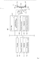
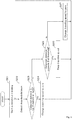
- is a flowchart showing a flow of a controller device according to the first embodiment.
- Fig. 7
- is a view explaining a way of changing a traveling speed based on a detected direction according to a second embodiment.
- Fig. 8
- is a flowchart showing a flow of a controller device according to the second embodiment.
- Fig. 9
- is a side overall view of the working vehicle.
- With reference to the drawings, an embodiment of the present invention will be described below.
- First, a tractor, one of a working
vehicle 1, will be described. As shown inFIG. 9 , thetractor 1 has atraveling vehicle 3 having atraveling device 7, aprime mover 4, and atransmission device 5. Thetraveling vehicle 3 has acabin 9, and adriver seat 10 is located in thecabin 9. In the following description, a forward direction of a driver sitting on thedriver seat 10 of the working vehicle 1 (a direction of an arrowed line A1 inFIG. 9 ) is referred to as the front, a rearward direction of the driver (a direction of an arrowed line A2 inFIG. 9 ) is referred to as the rear, a leftward direction of the driver (a direction of a front surface side ofFIG. 9 ) is referred to as the left, and a rightward direction of the driver (a direction of a back surface side ofFIG. 9 ) is referred to as the right. In the description, a horizontal direction orthogonal to a fore-and-aft direction of thetractor 1 is referred to as a width direction. Thetraveling device 7 hasfront wheels 7F andrear wheels 7R. Thefront wheels 7F may be of tire types or crawler types. Therear wheels 7R may also be of the tire types or the crawler types. Theprime mover 4 is a diesel engine, an electric motor, or the like. Thetransmission device 5 is configured to switch a propulsion force of thetraveling device 7 by shifting gears, and is configured to switch a traveling direction of thetraveling device 7 between forward and backward. Thetraveling vehicle 3 has thecabin 9, and thedriver seat 10 is located in thecabin 9. - In addition, a connecting
portion 8 constituted of a three-point linkage mechanism or the like is located in a rear portion of thetraveling vehicle 3. The connectingportion 8 is a lifting device. A workingdevice 2 can be attached to and detached from the lifting device. In this manner, the travelingvehicle 3 can be connected to the workingdevice 2. By connecting the workingdevice 2 to the lifting device, the workingdevice 2 can be towed by the travelingvehicle 3. That is, the workingdevice 2 is connected to a rear portion of the travelingvehicle 3 to perform work. The workingdevice 2 includes a digging device for digging potatoes and carrots, a cultivating device for cultivating, a fertilizer sprayer device for spreading fertilizer, a pesticide sprayer device for spreading pesticides, a harvester device for harvesting, a mower device for mowing grass, a tedder device for tedding grass, a raking device for raking grass, a baler device for baling grass, or the like.FIG. 9 shows an example of a digging device attached to the travelingvehicle 3 as the workingdevice 2. - As shown in
FIG. 1 , thetractor 1 has asteering device 11. Thesteering device 11 has a steering handle (that is, a steering wheel) 11a, a rotating shaft (that is, a steering shaft) 11b that rotates with therotating steering wheel 11a, and an assist mechanism (that is, a power steering mechanism) 11c that assists the steering of thesteering wheel 11a. Theassist mechanism 11c includes ahydraulic pump 21, acontrol valve 22 to which hydraulic fluid output from thehydraulic pump 21 is supplied, and asteering cylinder 23 to be operated by thecontrol valve 22. Thecontrol valve 22 is a solenoid valve to be operated based on a control signal. For example, thecontrol valve 22 is a three-position switching valve configured to be switched by movement of a spool or the like. Thecontrol valve 22 can be switched by steering of thesteering shaft 11b. Thesteering cylinder 23 is connected to an arm (that is, a knuckle arm) 24 configured to change orientations of thefront wheels 7F. - Thus, when the
steering handle 11a is operated, the switching position and opening aperture of thecontrol valve 22 are switched according to operation of thesteering handle 11a, and thesteering cylinder 23 is stretched and contracted rightward and leftward according to the switching position and opening aperture of thecontrol valve 22 to change steering orientations of thefront wheels 7F. Thesteering device 11 described above is just an example and is not limited to the configuration described above. - As shown in
FIG. 2 , the lifting device haslift arms 8a,lower links 8b, atop link 8c,lift rods 8d, and liftcylinders 8e. Front ends of thelift arms 8a are supported swingably upward or downward on a rear upper portion of a case (that is, a transmission case) that houses thetransmission device 5. Thelift arm 8a is swung (lifted and lowered) by driving of thelift cylinders 8e. - The
lift cylinders 8e are constituted of hydraulic cylinders. Thelift cylinders 8e are connected to thehydraulic pump 21 via thecontrol valve 22. Thecontrol valve 22 is a solenoid valve or the like, and stretches and contracts thelift cylinders 8e. - Front ends of the
lower links 8b are supported swingably upward and downward on a rear lower portion of thetransmission device 5. A front end of thetop link 8c is supported on the rear portion of thetransmission device 5 above thelower links 8b and swingable upward and downward. Thelift rods 8d connect thelift arms 8a to thelower links 8b. The workingdevice 2 is connected to rear portions of thelower links 8b and thetop link 8c. When thelift cylinders 8e are driven (stretched and contracted), thelift arms 8a are lifted and lowered, and thelower links 8b connected to thelift arms 8a via thelift rods 8d are lifted and lowered. In this manner, the workingdevice 2 is swung upward or downward (that is, lifted and lowered) with the front portions of thelower links 8b as fulcrums. - As shown in
FIGS. 1 and9 , thetractor 1 has aposition detector 40. Theposition detector 40 detects a position of the travelingvehicle 3. In the embodiment, theposition detector 40 is, for example, apositioning device 40. Thepositioning device 40 is configured to detect its own position (that is, positioning information including latitude and longitude) through a satellite positioning system (that is, positioning satellites) such as D-GPS, GPS, GLONASS, HOKUTO, GALILEO, or MICHIBIKI. That is, thepositioning device 40 receives satellite signals (that is, positions of positioning satellites, transmission times, correction information, and the like) transmitted from the positioning satellites, and detects a position of the tractor 1 (for example, latitude and longitude), that is, a vehicle position W1, based on the satellite signals. As shown inFIG. 1 , thepositioning device 40 has areceiver 41 and an inertial measurement unit (IMU) 42. Thereceiver 41 has an antenna to receive satellite signals transmitted from positioning satellites, and is attached to the travelingvehicle 3 separately from theinertial measurement unit 42. In the embodiment, thereceiver 41 is attached to an upper portion of the cabin 9 (that is, aroof 9a) mounted on the travelingvehicle 3. The attachment location of thereceiver 41 is not limited to that of the embodiment. - The
inertial measurement unit 42 has an acceleration sensor to detect acceleration, a gyro sensor to detect an angular velocity, and the like. Theinertial measurement unit 42 is located on the travelingvehicle 3, for example, below thedriver seat 10, and capable of detecting a roll angle, a pitch angle, a yaw angle, and the like of the travelingvehicle 3. - In the embodiment, the
position detector 40 is thepositioning device 40 configured to detect a position of the travelingvehicle 3 based on satellite signals, but it is sufficient for theposition detector 40 to be capable of detecting a position of the travelingvehicle 3; thus, theposition detector 40 may be configured to detect a position of the travelingvehicle 3 based on the acceleration detected by theinertial measurement unit 42 and predetermined positional information, and is not limited to the above-mentioned configuration. - As shown in
FIG. 1 , thetractor 1 has acontroller 60 and astorage 62. Thecontroller 60 controls a traveling system, a working system, and the like in thetractor 1. Thestorage 62 is a nonvolatile memory or the like, and stores various information relating to the controls of thecontroller 60. - As shown in
FIG. 1 , thecontroller 60 has anautonomous traveling controller 61 configured to control autonomous traveling of thetractor 1. Theautonomous traveling controller 61 is constituted of electrical/electronic circuits installed in thecontroller 60, computer programs stored in a CPU, or the like. When starting autonomous traveling, the autonomous travelingcontroller 61 controls thecontrol valve 22 of thesteering device 11 so that the travelingvehicle 3 travels on a scheduled traveling route L. In addition, when starting autonomous traveling, the autonomous travelingcontroller 61 controls a vehicle speed (that is, a traveling speed) of thetractor 1 by autonomously changing a gear shift of thetransmission device 5, a revolving speed of theprime mover 4, and the like.FIG. 3A shows an example of the scheduled traveling route L of the tractor. The scheduled traveling route L includes a straight traveling section L1 in which thetractor 1 travels straight and a turn section L2 in which thetractor 1 turns. When starting autonomous traveling, the autonomous travelingcontroller 61 controls different traveling speeds respectively in the straight traveling section L1 and in the turn section L2. For example, in the straight traveling section L1, the autonomous travelingcontroller 61 sets a traveling speed to a speed α. On the other hand, in the turn section L2, the autonomous travelingcontroller 61 sets a traveling speed to a speed β (β > α), which is slower than the speed α. Note that the autonomous travelingcontroller 61 may divide the straight traveling section L1 into a plurality of sections and set different traveling speeds respectively for each of the sections; thus, a control method for the traveling speed is not limited to the above-mentioned configuration. - As shown in
FIG. 3B , when a deviation between the vehicle position W1 and the scheduled traveling route L is less than a threshold value in a state where thetractor 1 is autonomously traveling, the autonomous travelingcontroller 61 keeps a rotation angle of the steering shaft (that is, a rotation shaft) 11b. When a deviation between the vehicle position W1 and the scheduled travel route L is the threshold value or more and thetractor 1 is positioning leftward relative to the scheduled travel route L, the autonomous travelingcontroller 61 rotates thesteering shaft 11b so that a steering direction of thetractor 1 is orientated rightward. When a deviation between the vehicle position W1 and the scheduled traveling route L is the threshold value or more and thetractor 1 is positioning rightward relative to the scheduled traveling route L, the autonomous travelingcontroller 61 rotates thesteering shaft 11b so that a steering direction of thetractor 1 is orientated leftward. In the above-mentioned embodiment, the steering angle of thesteering device 11 is changed based on the deviation between the vehicle position W1 and the scheduled traveling route L. However, when an orientation of the scheduled traveling route L is different from an orientation (that is, a vehicle orientation) F1 of a advancing direction (that is, a traveling direction) of the tractor 1 (that is, the traveling vehicle 3), that is, when an angle θg of the vehicle orientation F1 relative to the scheduled traveling route L is a threshold value or more, the autonomous travelingcontroller 61 may determine a steering angle so that the angle θg can be zero (that is, the vehicle orientation F1 matches an orientation of the scheduled traveling route L). In addition, the autonomous travelingcontroller 61 may determine the final steering angle in autonomous steering based on a steering angle obtained based on the deviation (that is, a positional deviation) and the steering angle obtained based on the orientation (that is, an orientational deviation). The setting of the steering angle in autonomous steering according to the embodiment is just an example and is not limited thereto. - As described above, the tractor 1 (that is, the traveling vehicle 3) is capable of autonomously traveling in accordance with the
controller 60. - The
tractor 1 is capable of keeping a relative distance within a certain range since thetractor 1 performs autonomous traveling by changing a traveling speed according to the relative distance from an worker M1 and a working machine M2 working behind the workingdevice 2 connected to thetractor 1 during the autonomous traveling. The worker M1 follows and moves with thetractor 1 to assist work performed by the workingdevice 2. When the workingdevice 2 is a digging device as shown inFIG. 9 , the worker M1 picks up and harvests crops as an assist work. On the other hand, the working machine M2 performs an assist work for the work performed by the workingdevice 2 while following and moving with thetractor 1. When the workingdevice 2 is a digging device as shown inFIG. 9 , the working machine M2 performs an assist work such as loading of crops into containers. For convenience of explanation, the worker M1 and the working machine M2 will be described as a working group M in the following description. Theautonomous traveling controller 61 controls a traveling speed corresponding to the scheduled traveling route L, and changes the traveling speed based on a relative distance between the workingdevice 2 and the working group M performing work behind the workingdevice 2. The workingvehicle 1 has adistance detector 70. As shown inFIG. 9 , thedistance detector 70 is located, for example, at a rear portion of the travelingvehicle 3, and detects a relative distance (that is, detected distance x2) between the workingdevice 2 and the working group M. Thedistance detector 70 is, for example, a laser scanner that detects the working group M behind the workingdevice 2 and detects a distance to the working group M. The laser scanner has a detection angle range of about 270 degrees rearward of the travelingvehicle 3 and can detect the working group M positioning behind the workingdevice 2. As shown inFIG. 4 , the laser scanner is capable of detecting the working group M at least in a target area E on a plane. In the embodiment, thedistance detector 70 is a laser scanner. Thedistance detector 70 is provided to detect the relative distance between the workingdevice 2 and the working group M behind the workingdevice 2, and may be, for example, constituted of a radar sensor, a sonar sensor, or the like, or constituted of an imaging device configured to capture images behind the workingdevice 2 to detect the relative distance. - The target area E includes at least an area overlapping an area where the working
device 2 performs work. Specifically, one side (that is, a left side) of the target area E in the width direction matches one side (that is, a left side) of an area where the workingdevice 2 perform work or is offset toward the one side (the left side) of the area, and the other side (that is, a right side) of the target area E in the width direction matches the other side (that is, a right side) of the area where the workingdevice 2 perform work or is offset toward the other side (the right side) of the area. A length y2 of the target area E in the width direction is the same as or longer than a length y1 of the area where the workingdevice 2 performs work in the width direction (that is, y2 ≥ y1). In the embodiment, as shown inFIG. 4 , the left side of the target area E in the width direction matches the left side of the area where the workingdevice 2 performs work, and the right side of the target area E in the width direction matches the right side of the area where the workingdevice 2 performs work. In addition, the length y2 of the target area E in the width direction is the same as the length y1 of the area where the workingdevice 2 performs work in the width direction (that is, y2 = y1). This allows thedistance detector 70 to detect the working group M positioning at least in an area overlapping the area where the workingdevice 2 performs work. - As shown in
FIG. 1 , thedistance detector 70 has adetector 71 to detect the working group M and aprocessor 72 to process detection information output from thedetector 71. Thedetector 71 detects the working group M that is closest to thedetector 71 among the working groups M located in the target area E. Thedetector 71 causes a laser beam to be irradiated to the target area E and receives the reflected light of the laser beam reflected on the target area E. Theprocessor 72 detects a detected distance x2 between the workingdevice 2 and the working group M based on time from the start of irradiation by thedetector 71 to the receipt of the reflected light. Specifically, theprocessor 72 detects a relative distance x between the travelingvehicle 3 and the working group M based on the time from the start of irradiation by thedetector 71 to the receipt of the reflected light, and subtracts the relative distance x1 between the travelingvehicle 3 and the workingdevice 2 to detect the detected distance x2 (that is, x2 = x - x1). The relative distance x1 is a value preliminarily determined corresponding to the workingdevice 2 and stored in theprocessor 72. The relative distance x1 may be set and changed by a worker (that is, an operator) who operates a mobile terminal such as a personal computer (PC), a smart phone (multi-functional cell phone), a tablet or the like communicatively connected to thetractor 1 or operates a display device provided in thetractor 1, and, the relative distance x1 may be automatically set and changed in response to the workingdevice 2 connected to the connectingportion 8. Theprocessor 72 outputs the processed detected distance x2 to the autonomous travelingcontroller 61. - As shown in
FIG. 9 , thedistance detector 70 is attached to a rear upper portion of thecabin 9. Specifically, thedetector 71 is located on a lower portion of theroof 9a of thecabin 9 and directed rearward and downward. Thedistance detector 70 is located in a center portion of the lower portion of theroof 9a in the width direction. In the embodiment, thedistance detector 70 is attached to the rear upper portion of thecabin 9; however, it is sufficient for thedistance detector 70 to be capable of detecting the detecting distance x2 between the workingdevice 2 and the working group M. Accordingly, thedistance detector 70 may be attached to a pillar of thecabin 9 or to the workingdevice 2. - The
autonomous traveling controller 61 automatically changes gear shifts of thetransmission device 5, a revolving speed of theprime mover 4, and the like based on the detected distance x2, and changes a vehicle speed (that is, a traveling speed) of the tractor 1 (that is, the traveling vehicle 3). Specifically, the autonomous travelingcontroller 61 automatically changes gear shifts of thetransmission device 5, a revolving speed of theprime mover 4, and the like, according to a plurality of areas into which the target area E is divided based on distances from the workingdevice 2, and changes a traveling speed of the travelingvehicle 3. The plurality of areas includes a first area (referred to as a stopping area) E1, a second area (referred to as a deceleration area) E2, a third area (referred to as a speed-keeping area) E3, a fourth area (referred to as an acceleration area) E4, and a fifth area (referred to as a stopping area) E5. As shown inFIG. 4 , the target area E is divided into the first area E1, the second area E2, the third area E3, the fourth area E4, and the fifth area E5, in order from the area farthest from the workingdevice 2. The first area E1, the second area E2, the third area E3, the fourth area E4, and the fifth area E5 are divided based on a predetermined range or threshold. - The range and threshold are respectively a range or threshold corresponding to the detected distance x2, and are stored in advance, for example, in a
storage 62 arranged in the travelingvehicle 3. Thestorage 62 stores, for example, a predetermined range, a first threshold P3, and a second threshold P4 as the predetermined range or threshold. The predetermined range is a range defined by an upper limit P1 and a lower limit P2. The first threshold P3 is a value larger than the upper limit P1, and the second threshold P4 is a value smaller than the first threshold P3. In detail, the second threshold P4 is a value smaller than the first threshold P3 and smaller than the lower limit P2. - As shown in
FIG. 4 , the first area E1 is an area where the detected distance x2 is the first threshold P3 or more (that is, x ≥ P3). The second area E2 is an area where the detected distance x2 is less than the first threshold P3 and is the upper limit P1 or more (that is, P3 > x ≥ P1). The second area E2 is an area sandwiched between the first threshold P3 and the upper limit P1 (that is, a predetermined range). The third area E3 is an area where the detected distance x2 is less than the upper limit P1 and is larger than the lower limit P2 (that is, P1 > x > P2). The third area E3 is sandwiched between the upper limit P1 and the lower limit P2, and is an area matches the predetermined range. The fourth area E4 is an area where the detected distance x2 is the lower limit P2 or less and is larger than the second threshold P4 (that is, P2 ≥ x > P4). The fourth area E4 is an area sandwiched between the lower limit P2 and the second threshold P4 (that is, the predetermined range). The fifth area E5 is an area where the detected distance x2 is the second threshold P4 or less (that is, x ≤ P4). Theautonomous traveling controller 61 obtains the predetermined range, the first threshold P3, and the second threshold P4 from thestorage 62, and changes a traveling speed based on the predetermined range, the first threshold P3, and the second threshold P4, and the detected distance x2 output from thedistance detector 70. - The predetermined range (that is, the upper limit P1 and lower limit P2), the first threshold P3, and the second threshold P4 are predetermined values determined in advance and are stored in the
storage 62, and the autonomous travelingcontroller 61 has them by acquiring them from thestorage 62; however, the autonomous travelingcontroller 61 may have in advance the predetermined range, the first threshold P3, and the second threshold P4, and a source of acquisition thereof is not limited to the above-mentioned configuration. The predetermined range, the first threshold P3, and the second threshold P4 may be arbitrarily changeable. The values of the predetermined range, the first threshold P3, and the second threshold P4 can be changed by operating a mobile terminal such as a personal computer (PC), a smart phone (multi-function cell phone), a tablet or other computer communicatively connected to thetractor 1, or the display device provided in thetractor 1. In the embodiment, the autonomous travelingcontroller 61 changes a traveling speed according to the plurality of areas into which the target area E is divided based on distances from the workingdevice 2 however, it is sufficient for the autonomous travelingcontroller 61 to be capable of changing a traveling speed according to a distance from the workingdevice 2. And, shapes of the plurality of areas is not limited to substantially-rectangular shapes as shown inFIG. 4 , may be substantially-fan shapes or substantially-trapezoidal shape, and are not limited to the above-mentioned configuration. - Control by the autonomous traveling
controller 61 will be described below. Theautonomous traveling controller 61 changes a traveling speed to zero or to be increased when the detected distance x2 is the minimum of the predetermined range or less, does not change the traveling speed when the detected distance x2 is within the predetermined range, and changes the traveling speed to be decreased when the detected distance x2 is the maximum of the predetermined range or more. In detail, the autonomous travelingcontroller 61 changes the traveling speed to zero when the detected distance x2 is larger than the predetermined range and is the first threshold P3 or more. In addition, the autonomous travelingcontroller 61 changes the traveling speed to zero when the detected distance x2 is smaller than the predetermined range and is the second threshold P4 or less, and changes the traveling speed to be increased when the detected distance x2 is the minimum of the predetermined range or less and is larger than the second threshold P4. - To explain the control by the autonomous traveling
controller 61 in more detail, when the working group M closest to thedetector 71 is positioning in the first area E1 (that is, x ≥ P3), the autonomous travelingcontroller 61 changes the traveling speed to zero. Theautonomous traveling controller 61 stops the travelingvehicle 3 by controlling thetransmission device 5 and a braking device for braking thefront wheels 7F orrear wheels 7R. This allows the travelingvehicle 3 to stop traveling when the relative distance between the workingdevice 2 and the working group M becomes relatively large. In this manner, when the working group M is not moving, such as when the working group M is suspending work, the workingvehicle 1 can be restrained from proceeding with work ahead irrespective of the working group M without a stopping operation or the like on the travelingvehicle 3. - When the working group M closest to the
detector 71 is positioning in the second area E2 (that is, P3 > x ≥ P1), the autonomous travelingcontroller 61 changes a traveling speed to be reduced from a traveling speed corresponding to the scheduled traveling route L. Theautonomous traveling controller 61 decelerates the traveling speed in inverse proportion to a length of the detected distance x2 by shifting down gear shifts of thetransmission device 5, reducing a revolving speed of theprime mover 4, braking thefront wheels 7F orrear wheels 7R by the braking device, and the like. Specifically, for example, as shown inFIG. 5 , the autonomous travelingcontroller 61 calculates a traveling speed after the changing by multiplying the traveling speed corresponding to the scheduled traveling route L by a correction value determined based on a length of the detected distance x2 (that is, traveling speed after the changing = traveling speed corresponding to the scheduled traveling route L x correction value). In this manner, the autonomous travelingcontroller 61 changes the traveling speed to be decelerated when the relative distance from the working group M is relatively large in autonomous traveling. Accordingly, it is possible to keep a predetermined relative distance between the working group M and the workingdevice 2 without a stopping operation or the like on the travelingvehicle 3, and to suppress work by the working group M from being delayed from work by the workingdevice 2. In the embodiment, although the autonomous travelingcontroller 61 decelerates the traveling speed in inverse proportion to a length of the detected distance x2, the autonomous travelingcontroller 61 only needs to decelerate the traveling speed to be lower than a traveling speed corresponding to the scheduled traveling route L when the detected distance x2 is less than the first threshold P3 and is larger than the upper limit P1, and thus the autonomous travelingcontroller 61 may be configured to decelerate the traveling speed to be lower by a certain speed than a traveling speed corresponding to the scheduled traveling route L. - When the working group M closest to the
detector 71 is positioning in the third area E3 (that is, P1 > x > P2), the autonomous travelingcontroller 61 does not change the traveling speed from the traveling speed corresponding to the scheduled traveling route L. In other words, when the detected distance x2 is within the predetermined range, the autonomous travelingcontroller 61 does not change the traveling speed from the traveling speed corresponding to the scheduled traveling route L to keep the traveling speed. - When the working group M closest to the
detector 71 is positioning in the fourth area E4 (that is, P2 ≥ x > P4), the autonomous travelingcontroller 61 changes the traveling speed to be increased from the traveling speed corresponding to the scheduled traveling route L. Theautonomous traveling controller 61 increases the traveling speed in inverse proportion to a length of the detected distance x2 by shifting up the gear shift of thetransmission device 5 or increasing a revolving speed of theprime mover 4. For example, as in the case where the working group M closest to thedetector 71 is positioning in the second area E2, as shown inFIG. 5 , the autonomous travelingcontroller 61 calculates the traveling speed after the changing by multiplying the traveling speed corresponding to the scheduled traveling route L by a correction value determined according to a length of the detected distance x2 (that is, traveling speed after the changing = traveling speed corresponding to scheduled traveling route L x correction value). In this manner, the autonomous travelingcontroller 61 changes the traveling speed to be increased when a relative distance to the working group M becomes small in autonomous traveling. Accordingly, a predetermined relative distance can be kept between the workingdevice 2 and the working group M, and work by the working group M can be suppressed from overtaking work by the workingdevice 2. In the embodiment, although the autonomous travelingcontroller 61 increases a traveling speed in inverse proportion to a length of the detected distance x2, the autonomous travelingcontroller 61 only needs to increase the traveling speed to be higher than the traveling speed corresponding to the scheduled traveling route L when the detected distance x2 is the lower limit P2 or less and is larger than the second threshold P4, and thus may increase the traveling speed by a at a predetermined speed. - When the working group M closest to the
detector 71 is positioning in the fifth area E5 (that is, x ≤ P4), the autonomous travelingcontroller 61 changes the traveling speed to zero. Theautonomous traveling controller 61 stops the travelingvehicle 3 by controlling the braking device or thetransmission device 5. This allows the travelingvehicle 3 to stop traveling when a relative distance between the workingdevice 2 and the working group M is relatively small. Accordingly, it is possible to prevent the working group M from closely approaching the workingvehicle 1 to inhibit autonomous traveling, and is possible to suppress the working group M from contacting the workingvehicle 1. - According to the autonomous traveling
controller 61 described above, since a traveling speed of the travelingvehicle 3 is changed according to a relative distance between the workingdevice 2 and the working group M, the relative distance can be kept constant, and the working group M can continue to work without having to stop the workingvehicle 1 in accordance with work by the working group M following the workingvehicle 1. In addition, even when the workingvehicle 1 is not stopped, a predetermined relative distance can be kept between the workingdevice 2 and the working group M, and the work efficiency can be improved by reducing frequency of stopping the workingvehicle 1. - A flow of autonomous traveling by the autonomous traveling
controller 61 will be described below. - As shown in
FIG. 6 , after theengine 4 of thetractor 1 is started, the autonomous travelingcontroller 61 starts autonomous traveling of thetractor 1 when thecontroller 60 acquires a command to start the autonomous traveling of the tractor 1 (step S1). For example, thecontroller 60 acquires the command to start autonomous traveling from a mobile terminal such as a personal computer (PC), a smart phone (multi-functional cell phone), a tablet, or other computer communicatively connected to thetractor 1. Thecontroller 60 may acquire the start command at a predetermined time to start autonomous traveling, and the source of the start command is not limited to that of the above-mentioned configuration. When starting the autonomous traveling, the autonomous travelingcontroller 61 controls thecontrol valve 22 of thesteering device 11 so that the travelingvehicle 3 travels on the scheduled traveling route L. In addition, when starting the autonomous traveling, the autonomous travelingcontroller 61 controls a vehicle speed (that is, a traveling speed) of thetractor 1 by autonomously changing gear shifts of thetransmission device 5, a revolving speed of theprime mover 4, and the like. - When the autonomous traveling
controller 61 starts autonomous traveling of the tractor 1 (step S1), thedistance detector 70 detects the detected distance x2 (step S2). Specifically, thedetector 71 of thedistance detector 70 detects the working group M closest to thedetector 71 among the working groups M positioning in the target area E. Thedetector 71 irradiates a laser beam to the target area E and receives the reflected light of the laser beam reflected on the target area E. Theprocessor 72 of thedistance detector 70 detects the detected distance x2 between the workingdevice 2 and the working group M based on time from the start of irradiation by thedetector 71 to the receipt of the reflected light. Specifically, theprocessor 72 detects the relative distance x between the travelingvehicle 3 and the working group M based on the time from the start of irradiation of thedetector 71 to the receipt of the light, and subtracts the relative distance x1 between the travelingvehicle 3 and the workingdevice 2 to detect the detected distance x2. Theprocessor 72 outputs the processed detected distance x2 to the autonomous travelingcontroller 61. - When receiving the detected distance x2 from the
distance detector 70, the autonomous travelingcontroller 61 autonomously changes gear shifts of thetransmission device 5 and a revolving speed of theprime mover 4, and the like according to the detected distance x2, and changes a vehicle speed (that is, a traveling speed) of the tractor 1 (step S3 to step S11). Specifically, the autonomous travelingcontroller 61 first acquires the first threshold P3 from thestorage 62, and checks whether the detected distance x2 output from thedistance detector 70 is the first threshold P3 or more (step S3). When the detected distance x2 is the first threshold P3 or more (step S3, Yes), the autonomous travelingcontroller 61 changes the traveling speed to zero (step S4). In other words, when the working group M closest to thedetector 71 is positioning in the first area E1, the autonomous travelingcontroller 61 changes the traveling speed to zero. Theautonomous traveling controller 61 stops the travelingvehicle 3 by controlling thetransmission device 5 and the braking device for braking thefront wheels 7F or therear wheels 7R. - When the detected distance x2 is less than the first threshold P3 (step S3, No), the autonomous traveling
controller 61 acquires the upper limit P1 from thestorage 62, and checks whether the detected distance x2 output from thedistance detector 70 is the upper limit P1 or more (step S5). When the detected distance x2 is the upper limit P1 or more, the autonomous travelingcontroller 61 changes the traveling speed to be decelerated from a traveling speed corresponding to the scheduled traveling route L (step S6). Theautonomous traveling controller 61 changes the traveling speed to be decelerated when the working group M closest to thedetector 71 is positioning in the second area E2, that is, when the detected distance x2 is less than the first threshold P3 and is the maximum of the predetermined range or more. Theautonomous traveling controller 61 shifts down gear shifts of thetransmission device 5, decreases a revolving speed of theprime mover 4, brakes thefront wheels 7F or therear wheels 7R by the braking device, and the like, to decelerate the traveling speed in inverse proportion to a length of the detected distance x2. - When the detected distance x2 is less than the upper limit P1 (step S5, No), the autonomous traveling
controller 61 acquires the lower limit P2 from thestorage 62 and checks whether the detected distance x2 output from thedistance detector 70 is larger than the lower limit P2 (step S7). When the detected distance x2 is larger than the lower limit P2 (step S7, Yes), the autonomous travelingcontroller 61 does not change the traveling speed from a traveling speed corresponding to the scheduled traveling route L (step S8). When the working group M closest to thedetector 71 is positioning in the third area E3, that is, when the detected distance x2 is within the predetermined range, the autonomous travelingcontroller 61 does not change the traveling speed from a traveling speed corresponding to the scheduled traveling route L to keep the traveling speed. - When the detected distance x2 is not larger than the lower limit P2 (step S7, No), the autonomous traveling
controller 61 acquires the second threshold P4 from thestorage 62, and checks whether the detected distance x2 output from thedistance detector 70 exceeds the second threshold P4 (step S9). When the detected distance x2 is larger than the second threshold P4 (step S9, Yes), the autonomous travelingcontroller 61 increases the traveling speed to be higher than a traveling speed corresponding to the scheduled traveling route L (step S10). When the working group M closest to thedetector 71 is positioning in the fourth area E4, that is, when the detected distance x2 is less than a predetermined range and is larger than the second threshold P4, the autonomous travelingcontroller 61 changes the traveling speed to be increased. Theautonomous traveling controller 61 shifts up gear shifts of thetransmission device 5 and increases a revolving speed of theprime mover 4, and the like to increase the traveling speed in inverse proportion to a length of the detected distance x2. - When the detected distance x2 is not larger than the second threshold P4 (step S9, No), that is, when the detected distance x2 is the second threshold P4 or less, the autonomous traveling
controller 61 changes the traveling speed to zero (step S11). In other words, when the working group M closest to thedetector 71 is positioning in the fifth area E5, the autonomous travelingcontroller 61 changes the traveling speed to zero. Theautonomous traveling controller 61 stops the travelingvehicle 3 by controlling the braking device and thetransmission device 5. - The working
vehicle 1 mentioned above includes the travelingvehicle 3 configured to be connected to the workingdevice 2, theposition detector 40 to detect a position of the travelingvehicle 3, the autonomous travelingcontroller 61 to perform autonomous steering of the travelingvehicle 3 based on the scheduled traveling route L and the position of the travelingvehicle 3 detected by theposition detector 40 and to control a traveling speed of the travelingvehicle 3 corresponding to the scheduled traveling route L, and thedistance detector 70 to detect the detected distance x2 between the workingdevice 2 and the worker M1 who works behind the workingdevice 2. Theautonomous traveling controller 61 changes the traveling speed based on the detected distance x2. - According to the above-mentioned configuration, the autonomous traveling
controller 61 is capable of changing a traveling speed of the travelingvehicle 3 according to a position of the worker M1 who works behind the workingdevice 2. Thus, a relative distance between the workingdevice 2 and the worker M1 can be kept appropriately, the coordination between the workingvehicle 1 and the work by the worker M1 can be easily realized, and the work can be continued without preliminarily lowering a speed of autonomous traveling of the workingvehicle 1 or without starting or stopping the workingvehicle 1. - In addition, the working
vehicle 1 includes the travelingvehicle 3 configured to be connected to the workingdevice 2, theposition detector 40 to detect a position of the travelingvehicle 3, the autonomous travelingcontroller 61 to perform autonomous steering of the travelingvehicle 3 based on the scheduled traveling route L and the position of the travelingvehicle 3 detected by theposition detector 40 and to control a traveling speed of the travelingvehicle 3 corresponding to the scheduled traveling route L, and thedistance detector 70 to detect the detected distance x2 between the workingdevice 2 and the working machine M2 which is operated behind the workingdevice 2. Theautonomous traveling controller 61 changes the traveling speed based on the detected distance x2. - According to the above-mentioned configuration, the autonomous traveling
controller 61 is capable of changing a traveling speed of the travelingvehicle 3 according to a position of the working machine M2 who works behind the workingdevice 2. Thus, a relative distance between the workingdevice 2 and the working machine M2 can be kept appropriately, the coordination between the workingvehicle 1 and the work by the working machine M2 can be easily realized, and the work can be continued without preliminarily lowering a speed of autonomous traveling of the workingvehicle 1 or without starting or stopping the workingvehicle 1. - In addition, the autonomous traveling
controller 61 changes the traveling speed to zero or to be increased when the detected distance x2 is the minimum of the predetermined range or less, does not change the traveling speed when the detected distance x2 is in the predetermined range, and changes the traveling speed to be decreased when the detected distance x2 is the maximum of the predetermined range or more. - According to the above-mentioned configuration, the autonomous traveling
controller 61 increases a traveling speed when a relative distance to the working group M (that is, the worker M1 or the working machine M2) is small in autonomous traveling, and decreases the traveling speed when the relative distance to the working group M is large. Accordingly, a predetermined relative distance can be kept between the workingdevice 2 and the working group M, and work by the working group M can be suppressed from delaying behind or overtaking work by the workingdevice 2. In this manner, it is possible to keep a predetermined relative distance between the workingdevice 2 and the working group M without stopping the workingvehicle 1, and thus to suppress frequency of stopping the workingvehicle 1, thereby improving work efficiency. - In addition, the autonomous traveling
controller 61 has the first threshold P3 larger than the predetermined range, and changes the traveling speed to zero when the detected distance x2 is larger than the predetermined range and is the first threshold P3 or more. - According to the above-mentioned configuration, when a relative distance between the working
device 2 and the working group M becomes relatively large, the workingdevice 2 can stop traveling. Accordingly, during the working group M is not moving, such as during the working group M is suspending work, the workingvehicle 1 can be restrained from working ahead of the working group M irrespective of the work by the working group M. - In addition, the autonomous traveling
controller 61 has the second threshold P4 smaller than the predetermined range, changes the traveling speed to zero when the detected distance x2 is smaller than the predetermined range and is the second threshold P4 or less, and changes the traveling speed to be increased when the detected distance x2 is the minimum of the predetermined range or less and is larger than the second threshold P4. - According to the above-mentioned configuration, the autonomous traveling
controller 61 increases a traveling speed when a relative distance to the working group M is small in autonomous traveling, so that a distance between the workingdevice 2 and the working group M can be kept at a predetermined relative distance, and work by the working group M can be suppressed from being delayed with respect to work by the workingdevice 2. On the other hand, when the relative distance between the workingdevice 2 and the working group M becomes smaller, the travelingvehicle 3 can stop traveling. Accordingly, it is possible to prevent the working group M from closely approaching the workingvehicle 1 to inhibit autonomous traveling, and is possible to suppress the working group M from contacting the workingvehicle 1. -
FIGS. 7 and8 show another embodiment (referred to as a second embodiment) of the workingvehicle 1. - The following description of the working
vehicle 1 according to the second embodiment focuses on configurations that differs from those of the above-mentioned embodiment (that is, the first embodiment), and the same sign is given the configurations shared with the first embodiment to omit detailed description. The workingvehicle 1 according to the first embodiment increases and decreases a vehicle speed (that is, a traveling speed) of thetractor 1 by autonomously changing gear shifts of thetransmission device 5, a revolving speed of theprime mover 4, and the like in accordance with the detected distance x2, thereby; however, the workingvehicle 1 according to the second embodiment keeps a vehicle speed (that is, a traveling speed) of thetractor 1 or change the vehicle speed to zero by autonomously changing gear shifts of thetransmission device 5, a revolving speed of theprime mover 4, and the like in accordance with the detected distance x2. The autonomous traveling control according to the second embodiment will be described in detail below. - The
autonomous traveling controller 61 keeps a vehicle speed (that is, a traveling speed) of thetractor 1 or changes the vehicle speed to zero according to a plurality of areas into which the target area E is divided based on distances from the workingdevice 2. The plurality of areas include a first area (referred to as a stopping area) E1a, a second area (referred to as a speed-keeping area) E2a, and a third area (referred to as a stopping area) E3a. As shown inFIG. 7 , the target area E is divided into the first area E1a, the second area E2a, and the third area E3a in order from the area farthest from the workingdevice 2. As shown inFIG. 7 , the first area E1a, the second area E2a, and the third area E3a are divided based on a predetermined range or threshold. - In the second embodiment, the threshold and range are, for example, the first threshold P3 and the second threshold P4. The first threshold P3 and the second threshold P4 are stored in the
storage 62. The first threshold P3 is a value preliminarily determined, and the second threshold P4 is a smaller value than the first threshold P3. - As shown in
FIG. 7 , the first area E1a is an area in which the detected distance x2 is the first threshold P3 or more. The second area E2a is an area in which the detected distance x2 is less than the first threshold P3 and is larger than the second threshold P4. The second area E2a is an area sandwiched between the first threshold P3 and the second threshold P4. The third area E3a is an area in which the detected distance x2 is the second threshold P4 or less. Theautonomous traveling controller 61 acquires the first threshold P3 and the second threshold P4 from thestorage 62, and keeps a traveling speed or changes the traveling speed to zero based on the first threshold P3, the second threshold P4, and the detected distance x2 output from thedistance detector 70. - The
autonomous traveling controller 61 changes the traveling speed to zero when the detected distance x2 is the first threshold P3 or more. Theautonomous traveling controller 61 changes the traveling speed to zero when the detected distance x2 is the second threshold P4 or less. Control by the autonomous travelingcontroller 61 will be described in detail below. - When the working group M closest to the
detector 71 is positioning in the first area E1a (that is, x ≥ P3), the autonomous travelingcontroller 61 changes the traveling speed to zero. Theautonomous traveling controller 61 stops the travelingvehicle 3 by controlling thetransmission device 5 and the braking device that performs braking of thefront wheels 7F orrear wheels 7R. This allows the travelingvehicle 3 to stop traveling when a relative distance between the workingdevice 2 and the working group M becomes relatively large. Accordingly, during the working group M is not moving, such as during the working group M is suspending work, the workingvehicle 1 can be restrained from working ahead of the working group M irrespective of the work by the working group M. - When the working group M closest to the
detector 71 is positioning in the second area E2a (that is, P3 > x > P4), the autonomous travelingcontroller 61 does not change the traveling speed from a traveling speed corresponding to the scheduled traveling route L. That is, when the detected distance x2 is less than the first threshold P3 and is larger than the second threshold P4, the autonomous travelingcontroller 61 does not change the traveling speed from a traveling speed corresponding to the scheduled traveling route L and keeps the traveling speed. - When the working group M closest to the
detector 71 is positioning in the third area E3a (that is, x ≤ P4), the autonomous travelingcontroller 61 changes the traveling speed to zero. Theautonomous traveling controller 61 stops the travelingvehicle 3 by controlling the braking device and thetransmission device 5. This allows the travelingvehicle 3 to stop traveling when a relative distance between the workingdevice 2 and the working group M is relatively small. Accordingly, it is possible to prevent the working group M from closely approaching the workingvehicle 1 to inhibit autonomous traveling, and is possible to suppress the working group M from contacting the workingvehicle 1. - A flow of autonomous traveling by the autonomous traveling
controller 61 will be described below. - As shown in
FIG. 8 , after theengine 4 of thetractor 1 is started, the autonomous travelingcontroller 61 starts autonomous traveling of thetractor 1 when thecontroller 60 acquires a command to start autonomous traveling of the tractor 1 (step S21). Thecontroller 60 acquires the command to start autonomous traveling from a mobile terminal such as a personal computer (PC), a smart phone (multi-functional cell phone), a tablet, or other computer communicatively connected to thetractor 1. When starting the autonomous traveling, the autonomous travelingcontroller 61 controls thecontrol valve 22 of thesteering device 11 so that the travelingvehicle 3 travels on the scheduled traveling route L. In addition, when starting the autonomous traveling, the autonomous travelingcontroller 61 controls a vehicle speed (that is, a traveling speed) of thetractor 1 by autonomously changing gear shifts of thetransmission device 5, a revolving speed of theprime mover 4, and the like. - When the autonomous traveling
controller 61 starts autonomous traveling of the tractor 1 (step S21), thedistance detector 70 detects the detected distance x2 (step S22). Thedetector 71 of thedistance detector 70 detects the working group M closest to thedetector 71 among the working groups M positioning in the target area E. Thedetector 71 irradiates a laser beam to the target area E and receives the reflected light of the laser beam reflected on the target area E. Theprocessor 72 of thedistance detector 70 detects the detected distance x2 between the workingdevice 2 and the working group M based on time from start of irradiation by thedetector 71 to receipt of the reflected light. Specifically, theprocessor 72 detects the relative distance x between the travelingvehicle 3 and the working group M based on the time from start of irradiation by thedetector 71 to receipt of the reflected light, and subtracts the relative distance x1 between the travelingvehicle 3 and the workingdevice 2 to detect the detected distance x2. Theprocessor 72 outputs the processed detected distance x2 to the autonomous travelingcontroller 61. - When receiving the detected distance x2 from the
distance detector 70, the autonomous travelingcontroller 61 automatically changes gear shifts of thetransmission device 5, a revolving speed of theprime mover 4, and the like based on the detected distance x2, and keeps the traveling speed or changes the traveling speed to zero (step S23 to step S27). Specifically, the autonomous travelingcontroller 61 first acquires the first threshold P3 from thestorage 62, and checks whether the detected distance x2 output from thedistance detector 70 is the first threshold P3 or more (step S23). When the detected distance x2 is the first threshold P3 or more (step S23, Yes), the autonomous travelingcontroller 61 changes the traveling speed to zero (step S24). In other words, when the working group M closest to thedetector 71 is positioning in the first area E1a, the autonomous travelingcontroller 61 changes the traveling speed to zero. Theautonomous traveling controller 61 stops the travelingvehicle 3 by controlling thetransmission device 5 and the braking device for braking thefront wheels 7F or therear wheels 7R. - When the detected distance x2 is less than the first threshold P3 (step S23, No), the autonomous traveling
controller 61 acquires the second threshold P4 from thestorage 62, and checks whether the detected distance x2 output from thedistance detector 70 is larger than the second threshold P4 (step S25). When the detected distance x2 is larger than the second threshold P4, the autonomous travelingcontroller 61 does not change the traveling speed from a traveling speed corresponding to the scheduled traveling route L (step S26). When the working group M closest to thedetector 71 is positioning in the second area E2a, that is, when the detected distance x2 is less than the first threshold P3 and is larger than the second threshold P4, the autonomous travelingcontroller 61 does not change the traveling speed from a traveling speed corresponding to the scheduled traveling route L and keeps the traveling speed. - When the detected distance x2 is not larger than the second threshold P4 (step S25, No), that is, when the detected distance x2 is the second threshold P4 or less, the autonomous traveling
controller 61 changes the traveling speed to zero (step S27). In other words, when the working group M closest to thedetector 71 is positioning in the third area E3a, the autonomous travelingcontroller 61 changes the traveling speed to zero. Theautonomous traveling controller 61 stops the travelingvehicle 3 by controlling the braking device and thetransmission device 5. - The
autonomous traveling controller 61 described above changes the traveling speed to zero when the detected distance x2 is the first threshold P3 or more. - According to the above-mentioned configuration, the traveling
vehicle 3 can stop traveling when a relative distance between the working group M (that is, the worker M1 or the working machine M2) and the workingdevice 2 is large. Accordingly, during the working group M is not moving, such as during the working group M is suspending work, the workingvehicle 1 can be restrained from working ahead of the working group M irrespective of the work by the working group M. - In addition, the autonomous traveling
controller 61 changes the traveling speed to zero when the detected distance x2 is less than or equal to the second threshold P4, which is smaller than the first threshold P3. - According to the above-mentioned configuration, the traveling
vehicle 3 can stop traveling when a relative distance between the working group M and the workingdevice 2 is small. Accordingly, it is possible to prevent the working group M from closely approaching the workingvehicle 1 to inhibit autonomous traveling, and is possible to suppress the working group M from contacting the workingvehicle 1. - In the above description, the embodiment of the present invention has been explained. However, all the features of the embodiment disclosed in this application should be considered just as examples, and the embodiment does not restrict the present invention accordingly. A scope of the present invention is shown not in the above-described embodiment but in claims, and is intended to include all modifications within and equivalent to a scope of the claims.
-
- 1
- Working vehicle (Tractor)
- 2
- Working device
- 3
- Traveling vehicle
- 40
- Position detector (Positioning device)
- 61
- Autonomous traveling controller
- 70
- Distance detector
- L1
- Scheduled traveling route
- M1
- Worker
- M2
- Working machine
- P3
- First threshold
- P4
- Second threshold
- X
- Detected distance
Claims (7)
- A working vehicle comprising:- a traveling vehicle configured to be connected to a working device;- a position detector to detect a position of the traveling vehicle;- an autonomous traveling controller to perform autonomous steering of the traveling vehicle based on a scheduled traveling route and the position of the traveling vehicle detected by the position detector and to control a traveling speed of the traveling vehicle corresponding to the scheduled traveling route; and- a distance detector to detect a detected distance between the working device and a worker who works behind the working device, wherein- the autonomous traveling controller changes the traveling speed based on the detected distance.
- A working vehicle comprising:- a traveling vehicle configured to be connected to a working device;- a position detector to detect a position of the traveling vehicle;- an autonomous traveling controller to perform autonomous steering of the traveling vehicle based on a scheduled traveling route and the position of the traveling vehicle detected by the position detector and to control a traveling speed of the traveling vehicle corresponding to the scheduled traveling route; and- a distance detector to detect a detected distance between the working device and a working machine which is operated behind the working device, wherein- the autonomous traveling controller changes the traveling speed based on the detected distance.
- The working vehicle according to claim 1 or 2, wherein- the autonomous traveling controller- changes the traveling speed to zero or to be increased when the detected distance is the minimum of a predetermined range or less,- does not change the traveling speed when the detected distance is in the predetermined range, and- changes the traveling speed to be decreased when the detected distance is the maximum of the predetermined range or more.
- The working vehicle according to claim 3, wherein- the autonomous traveling controller- has a first threshold larger than the predetermined range, and- changes the traveling speed to zero when the detected distance is larger than the predetermined range and is the first threshold or more.
- The working vehicle according to claim 3 or 4, wherein- the autonomous traveling controller- has a second threshold smaller than the predetermined range,- changes the traveling speed to zero when the detected distance is smaller than the predetermined range and is the second threshold or less, and- changes the traveling speed to be increased when the detected distance is the minimum of the predetermined range or less and is larger than the second threshold.
- The working vehicle according to claim 1 or 2, wherein the autonomous traveling controller changes the traveling speed to zero when the detected distance is the first threshold or more.
- The working vehicle according to claim 6, wherein the autonomous traveling controller changes the traveling speed to zero when the detected distance is a second threshold or less, the second threshold being smaller than the first threshold.
Applications Claiming Priority (2)
| Application Number | Priority Date | Filing Date | Title |
|---|---|---|---|
| JP2018243535A JP2020103093A (en) | 2018-12-26 | 2018-12-26 | Work vehicle |
| PCT/JP2019/049859 WO2020137813A1 (en) | 2018-12-26 | 2019-12-19 | Work vehicle |
Publications (2)
| Publication Number | Publication Date |
|---|---|
| EP3903553A1 true EP3903553A1 (en) | 2021-11-03 |
| EP3903553A4 EP3903553A4 (en) | 2022-09-28 |
Family
ID=71128574
Family Applications (1)
| Application Number | Title | Priority Date | Filing Date |
|---|---|---|---|
| EP19903108.9A Pending EP3903553A4 (en) | 2018-12-26 | 2019-12-19 | WORK VEHICLE |
Country Status (4)
| Country | Link |
|---|---|
| US (1) | US12025986B2 (en) |
| EP (1) | EP3903553A4 (en) |
| JP (1) | JP2020103093A (en) |
| WO (1) | WO2020137813A1 (en) |
Families Citing this family (7)
| Publication number | Priority date | Publication date | Assignee | Title |
|---|---|---|---|---|
| US10795351B2 (en) * | 2016-07-19 | 2020-10-06 | Raven Industries, Inc. | System and method for autonomous control of agricultural machinery and equipment |
| JP7074657B2 (en) * | 2018-12-20 | 2022-05-24 | 株式会社クボタ | Work vehicle |
| EP4028844B1 (en) | 2019-09-09 | 2024-11-27 | Mtd Products Inc. | Real time kinematics power equipment device with auto-steering |
| JP7769589B2 (en) * | 2022-06-15 | 2025-11-13 | ヤンマーホールディングス株式会社 | Autonomous driving method, automatic driving system, and automatic driving program |
| JP7847844B2 (en) * | 2022-10-12 | 2026-04-20 | 国立研究開発法人農業・食品産業技術総合研究機構 | Work vehicle control device and work vehicle control method |
| US12353209B2 (en) * | 2023-01-04 | 2025-07-08 | Kubota Corporation | Agricultural support system, and device and method to generate travel route for hailed agricultural machine |
| JP2024116593A (en) * | 2023-02-16 | 2024-08-28 | ヤンマーホールディングス株式会社 | Automatic steering method, automatic steering system, and automatic steering program |
Family Cites Families (12)
| Publication number | Priority date | Publication date | Assignee | Title |
|---|---|---|---|---|
| JP2602175Y2 (en) * | 1992-07-15 | 1999-12-27 | セイレイ工業株式会社 | Automatic traveling device for harvesting vehicles such as vegetables |
| JPH06242823A (en) * | 1993-02-18 | 1994-09-02 | Toshiba Corp | Automatic portable baggage carrier |
| EP3104245A4 (en) * | 2014-02-06 | 2017-11-01 | Yanmar Co., Ltd. | Method for setting travel path of autonomous travel work vehicle |
| JP6368964B2 (en) * | 2014-03-26 | 2018-08-08 | ヤンマー株式会社 | Control device for work vehicle |
| ES2718580T3 (en) * | 2014-03-26 | 2019-07-02 | Yanmar Co Ltd | Autonomous Displacement Work Vehicle |
| US20170135277A1 (en) | 2014-03-28 | 2017-05-18 | Yanmar Co., Ltd. | Autonomously traveling work vehicle |
| WO2016002623A1 (en) * | 2014-06-30 | 2016-01-07 | ヤンマー株式会社 | Parallel travel work system |
| JP6219790B2 (en) | 2014-07-29 | 2017-10-25 | 株式会社クボタ | Work vehicle coordination system |
| JP2016095659A (en) * | 2014-11-13 | 2016-05-26 | ヤンマー株式会社 | Multiple unit parallel operation system |
| KR102113386B1 (en) | 2014-11-13 | 2020-05-20 | 얀마 가부시키가이샤 | Agricultural work vehicle |
| EP3633481A1 (en) * | 2016-03-09 | 2020-04-08 | Yanmar Co., Ltd. | Work vehicle |
| JP6689126B2 (en) * | 2016-04-26 | 2020-04-28 | ヤンマー株式会社 | Work vehicle control system |
-
2018
- 2018-12-26 JP JP2018243535A patent/JP2020103093A/en active Pending
-
2019
- 2019-12-19 WO PCT/JP2019/049859 patent/WO2020137813A1/en not_active Ceased
- 2019-12-19 EP EP19903108.9A patent/EP3903553A4/en active Pending
-
2021
- 2021-06-21 US US17/352,472 patent/US12025986B2/en active Active
Also Published As
| Publication number | Publication date |
|---|---|
| US20210311488A1 (en) | 2021-10-07 |
| EP3903553A4 (en) | 2022-09-28 |
| WO2020137813A1 (en) | 2020-07-02 |
| US12025986B2 (en) | 2024-07-02 |
| JP2020103093A (en) | 2020-07-09 |
Similar Documents
| Publication | Publication Date | Title |
|---|---|---|
| US12025986B2 (en) | Working vehicle | |
| JP7355902B2 (en) | Automatic driving system for work vehicles and control method for work vehicles | |
| EP3491904B1 (en) | Agricultural work vehicle | |
| US11805720B2 (en) | Automatic travel system for work vehicle | |
| WO2020235471A1 (en) | Automatic travel system for work vehicle | |
| KR20210107619A (en) | Obstacle detection system for work vehicles | |
| KR102283927B1 (en) | Task vehicle control system | |
| WO2022065091A1 (en) | Automatic traveling system, automatic traveling method, and automatic traveling program | |
| JP7470843B2 (en) | Autonomous driving system and method | |
| CN111886516A (en) | Obstacle detection system for work vehicle | |
| EP3901722B1 (en) | Travel state display device and automated travel system | |
| JP7453954B2 (en) | automatic driving system | |
| JP7120878B2 (en) | Work equipment lifting control device | |
| JP2019170271A (en) | Work vehicle | |
| JP7317165B2 (en) | Obstacle detection system for work vehicles | |
| WO2020044805A1 (en) | Work vehicle autonomous travel system | |
| JP7772685B2 (en) | Work vehicles | |
| JP2024142696A (en) | Work vehicle control method, work vehicle control program, work vehicle control system, and work system | |
| JP2020102280A (en) | Work vehicle control system | |
| JP2024142697A (en) | Work vehicle control method, work vehicle control program, work vehicle control system, and work system | |
| JP2024076611A (en) | Work vehicle | |
| WO2025142090A1 (en) | Sensing system, work vehicle, sensing method, and computer program | |
| JP2018114926A (en) | Service car |
Legal Events
| Date | Code | Title | Description |
|---|---|---|---|
| STAA | Information on the status of an ep patent application or granted ep patent |
Free format text: STATUS: THE INTERNATIONAL PUBLICATION HAS BEEN MADE |
|
| PUAI | Public reference made under article 153(3) epc to a published international application that has entered the european phase |
Free format text: ORIGINAL CODE: 0009012 |
|
| STAA | Information on the status of an ep patent application or granted ep patent |
Free format text: STATUS: REQUEST FOR EXAMINATION WAS MADE |
|
| 17P | Request for examination filed |
Effective date: 20210618 |
|
| AK | Designated contracting states |
Kind code of ref document: A1 Designated state(s): AL AT BE BG CH CY CZ DE DK EE ES FI FR GB GR HR HU IE IS IT LI LT LU LV MC MK MT NL NO PL PT RO RS SE SI SK SM TR |
|
| DAV | Request for validation of the european patent (deleted) | ||
| DAX | Request for extension of the european patent (deleted) | ||
| A4 | Supplementary search report drawn up and despatched |
Effective date: 20220826 |
|
| RIC1 | Information provided on ipc code assigned before grant |
Ipc: B62D 15/02 20060101ALI20220822BHEP Ipc: G05D 1/02 20200101ALI20220822BHEP Ipc: A01B 69/00 20060101AFI20220822BHEP |
|
| STAA | Information on the status of an ep patent application or granted ep patent |
Free format text: STATUS: EXAMINATION IS IN PROGRESS |
|
| 17Q | First examination report despatched |
Effective date: 20251126 |