EP3903467B1 - System and method for cloud-based control-plane event monitor - Google Patents
System and method for cloud-based control-plane event monitor Download PDFInfo
- Publication number
- EP3903467B1 EP3903467B1 EP19903638.5A EP19903638A EP3903467B1 EP 3903467 B1 EP3903467 B1 EP 3903467B1 EP 19903638 A EP19903638 A EP 19903638A EP 3903467 B1 EP3903467 B1 EP 3903467B1
- Authority
- EP
- European Patent Office
- Prior art keywords
- cloud
- event
- control
- plane
- data set
- Prior art date
- Legal status (The legal status is an assumption and is not a legal conclusion. Google has not performed a legal analysis and makes no representation as to the accuracy of the status listed.)
- Active
Links
Images



Classifications
-
- H—ELECTRICITY
- H04—ELECTRIC COMMUNICATION TECHNIQUE
- H04L—TRANSMISSION OF DIGITAL INFORMATION, e.g. TELEGRAPHIC COMMUNICATION
- H04L43/00—Arrangements for monitoring or testing data switching networks
- H04L43/08—Monitoring or testing based on specific metrics, e.g. QoS, energy consumption or environmental parameters
- H04L43/0876—Network utilisation, e.g. volume of load or congestion level
-
- G—PHYSICS
- G06—COMPUTING OR CALCULATING; COUNTING
- G06F—ELECTRIC DIGITAL DATA PROCESSING
- G06F11/00—Error detection; Error correction; Monitoring
- G06F11/07—Responding to the occurrence of a fault, e.g. fault tolerance
- G06F11/0703—Error or fault processing not based on redundancy, i.e. by taking additional measures to deal with the error or fault not making use of redundancy in operation, in hardware, or in data representation
- G06F11/0706—Error or fault processing not based on redundancy, i.e. by taking additional measures to deal with the error or fault not making use of redundancy in operation, in hardware, or in data representation the processing taking place on a specific hardware platform or in a specific software environment
- G06F11/0709—Error or fault processing not based on redundancy, i.e. by taking additional measures to deal with the error or fault not making use of redundancy in operation, in hardware, or in data representation the processing taking place on a specific hardware platform or in a specific software environment in a distributed system consisting of a plurality of standalone computer nodes, e.g. clusters, client-server systems
-
- G—PHYSICS
- G06—COMPUTING OR CALCULATING; COUNTING
- G06F—ELECTRIC DIGITAL DATA PROCESSING
- G06F21/00—Security arrangements for protecting computers, components thereof, programs or data against unauthorised activity
- G06F21/50—Monitoring users, programs or devices to maintain the integrity of platforms, e.g. of processors, firmware or operating systems
- G06F21/55—Detecting local intrusion or implementing counter-measures
- G06F21/552—Detecting local intrusion or implementing counter-measures involving long-term monitoring or reporting
-
- G—PHYSICS
- G06—COMPUTING OR CALCULATING; COUNTING
- G06F—ELECTRIC DIGITAL DATA PROCESSING
- G06F21/00—Security arrangements for protecting computers, components thereof, programs or data against unauthorised activity
- G06F21/50—Monitoring users, programs or devices to maintain the integrity of platforms, e.g. of processors, firmware or operating systems
- G06F21/55—Detecting local intrusion or implementing counter-measures
- G06F21/554—Detecting local intrusion or implementing counter-measures involving event detection and direct action
-
- G—PHYSICS
- G06—COMPUTING OR CALCULATING; COUNTING
- G06F—ELECTRIC DIGITAL DATA PROCESSING
- G06F21/00—Security arrangements for protecting computers, components thereof, programs or data against unauthorised activity
- G06F21/60—Protecting data
- G06F21/604—Tools and structures for managing or administering access control systems
-
- G—PHYSICS
- G06—COMPUTING OR CALCULATING; COUNTING
- G06F—ELECTRIC DIGITAL DATA PROCESSING
- G06F21/00—Security arrangements for protecting computers, components thereof, programs or data against unauthorised activity
- G06F21/60—Protecting data
- G06F21/62—Protecting access to data via a platform, e.g. using keys or access control rules
- G06F21/6218—Protecting access to data via a platform, e.g. using keys or access control rules to a system of files or objects, e.g. local or distributed file system or database
-
- G—PHYSICS
- G06—COMPUTING OR CALCULATING; COUNTING
- G06F—ELECTRIC DIGITAL DATA PROCESSING
- G06F9/00—Arrangements for program control, e.g. control units
- G06F9/06—Arrangements for program control, e.g. control units using stored programs, i.e. using an internal store of processing equipment to receive or retain programs
- G06F9/44—Arrangements for executing specific programs
- G06F9/455—Emulation; Interpretation; Software simulation, e.g. virtualisation or emulation of application or operating system execution engines
- G06F9/45533—Hypervisors; Virtual machine monitors
-
- H—ELECTRICITY
- H04—ELECTRIC COMMUNICATION TECHNIQUE
- H04L—TRANSMISSION OF DIGITAL INFORMATION, e.g. TELEGRAPHIC COMMUNICATION
- H04L41/00—Arrangements for maintenance, administration or management of data switching networks, e.g. of packet switching networks
- H04L41/08—Configuration management of networks or network elements
- H04L41/0803—Configuration setting
- H04L41/0813—Configuration setting characterised by the conditions triggering a change of settings
- H04L41/0816—Configuration setting characterised by the conditions triggering a change of settings the condition being an adaptation, e.g. in response to network events
-
- H—ELECTRICITY
- H04—ELECTRIC COMMUNICATION TECHNIQUE
- H04L—TRANSMISSION OF DIGITAL INFORMATION, e.g. TELEGRAPHIC COMMUNICATION
- H04L41/00—Arrangements for maintenance, administration or management of data switching networks, e.g. of packet switching networks
- H04L41/08—Configuration management of networks or network elements
- H04L41/0894—Policy-based network configuration management
-
- H—ELECTRICITY
- H04—ELECTRIC COMMUNICATION TECHNIQUE
- H04L—TRANSMISSION OF DIGITAL INFORMATION, e.g. TELEGRAPHIC COMMUNICATION
- H04L41/00—Arrangements for maintenance, administration or management of data switching networks, e.g. of packet switching networks
- H04L41/08—Configuration management of networks or network elements
- H04L41/0895—Configuration of virtualised networks or elements, e.g. virtualised network function or OpenFlow elements
-
- H—ELECTRICITY
- H04—ELECTRIC COMMUNICATION TECHNIQUE
- H04L—TRANSMISSION OF DIGITAL INFORMATION, e.g. TELEGRAPHIC COMMUNICATION
- H04L41/00—Arrangements for maintenance, administration or management of data switching networks, e.g. of packet switching networks
- H04L41/40—Arrangements for maintenance, administration or management of data switching networks, e.g. of packet switching networks using virtualisation of network functions or resources, e.g. SDN or NFV entities
-
- H—ELECTRICITY
- H04—ELECTRIC COMMUNICATION TECHNIQUE
- H04L—TRANSMISSION OF DIGITAL INFORMATION, e.g. TELEGRAPHIC COMMUNICATION
- H04L43/00—Arrangements for monitoring or testing data switching networks
- H04L43/04—Processing captured monitoring data, e.g. for logfile generation
-
- H—ELECTRICITY
- H04—ELECTRIC COMMUNICATION TECHNIQUE
- H04L—TRANSMISSION OF DIGITAL INFORMATION, e.g. TELEGRAPHIC COMMUNICATION
- H04L43/00—Arrangements for monitoring or testing data switching networks
- H04L43/20—Arrangements for monitoring or testing data switching networks the monitoring system or the monitored elements being virtualised, abstracted or software-defined entities, e.g. SDN or NFV
-
- H—ELECTRICITY
- H04—ELECTRIC COMMUNICATION TECHNIQUE
- H04L—TRANSMISSION OF DIGITAL INFORMATION, e.g. TELEGRAPHIC COMMUNICATION
- H04L63/00—Network architectures or network communication protocols for network security
- H04L63/02—Network architectures or network communication protocols for network security for separating internal from external traffic, e.g. firewalls
- H04L63/0227—Filtering policies
- H04L63/0263—Rule management
-
- H—ELECTRICITY
- H04—ELECTRIC COMMUNICATION TECHNIQUE
- H04L—TRANSMISSION OF DIGITAL INFORMATION, e.g. TELEGRAPHIC COMMUNICATION
- H04L63/00—Network architectures or network communication protocols for network security
- H04L63/14—Network architectures or network communication protocols for network security for detecting or protecting against malicious traffic
- H04L63/1408—Network architectures or network communication protocols for network security for detecting or protecting against malicious traffic by monitoring network traffic
- H04L63/1425—Traffic logging, e.g. anomaly detection
-
- H—ELECTRICITY
- H04—ELECTRIC COMMUNICATION TECHNIQUE
- H04L—TRANSMISSION OF DIGITAL INFORMATION, e.g. TELEGRAPHIC COMMUNICATION
- H04L63/00—Network architectures or network communication protocols for network security
- H04L63/14—Network architectures or network communication protocols for network security for detecting or protecting against malicious traffic
- H04L63/1433—Vulnerability analysis
-
- H—ELECTRICITY
- H04—ELECTRIC COMMUNICATION TECHNIQUE
- H04L—TRANSMISSION OF DIGITAL INFORMATION, e.g. TELEGRAPHIC COMMUNICATION
- H04L63/00—Network architectures or network communication protocols for network security
- H04L63/20—Network architectures or network communication protocols for network security for managing network security; network security policies in general
-
- H—ELECTRICITY
- H04—ELECTRIC COMMUNICATION TECHNIQUE
- H04L—TRANSMISSION OF DIGITAL INFORMATION, e.g. TELEGRAPHIC COMMUNICATION
- H04L67/00—Network arrangements or protocols for supporting network services or applications
- H04L67/01—Protocols
- H04L67/10—Protocols in which an application is distributed across nodes in the network
- H04L67/1097—Protocols in which an application is distributed across nodes in the network for distributed storage of data in networks, e.g. transport arrangements for network file system [NFS], storage area networks [SAN] or network attached storage [NAS]
-
- H—ELECTRICITY
- H04—ELECTRIC COMMUNICATION TECHNIQUE
- H04L—TRANSMISSION OF DIGITAL INFORMATION, e.g. TELEGRAPHIC COMMUNICATION
- H04L67/00—Network arrangements or protocols for supporting network services or applications
- H04L67/50—Network services
- H04L67/51—Discovery or management thereof, e.g. service location protocol [SLP] or web services
-
- H—ELECTRICITY
- H04—ELECTRIC COMMUNICATION TECHNIQUE
- H04L—TRANSMISSION OF DIGITAL INFORMATION, e.g. TELEGRAPHIC COMMUNICATION
- H04L43/00—Arrangements for monitoring or testing data switching networks
- H04L43/08—Monitoring or testing based on specific metrics, e.g. QoS, energy consumption or environmental parameters
Definitions
- US 2017/295199 A1 discloses systems and methods for cloud security monitoring and threat intelligence.
- US 2018/027006 A1 discloses methods and systems including a cyber intelligence system, a unified application firewall, and a cloud security fabric.
- US 2017/126469 A1 discloses a service control system that manages a set of containers operating within one or more computing hosts.
- PCI DSS Payment Card Industry Data Security Standard
- HIPAA Health Insurance Portability and Accountability Act
- SOC Service Organization Controls
- ISO 27001 International Organization for Standardization standards for information security management
- DRM Digital Rights Management
- SOX Sarbanes-Oxley
- Some embodiments of the cloud-based control-plane-event monitoring system and method according to the present teaching are used to monitor cloud, multi-cloud, hybrid and containerized infrastructure for intrusions, anomalies, vulnerabilities, trends, misconfigurations and other items across the host and infrastructure control plane.
- One key feature is that the system can monitor a common threat that is operating across or persisting on two different cloud environments that are part of the monitored cloud-based infrastructure. Detection of such multi-cloud operation is not possible on known monitoring systems because, for one thing, the events and methods of reporting of various events by the different infrastructures is not uniform. As such, it is not possible to directly correlate, process, compare and/or categorize events received from different cloud environments to generate conclusive policy violations or alert triggers.
- the method and systems of the present teaching collects, ingests and normalizes received control plane events from more than one cloud environment so that policy violation and/or alerts can be generated.
- the method and system of the present teaching can also produce actions including changes to processes and reconfigurations of infrastructure, which are based on the policy violations and/or alerts.
- cloud-based systems monitor methods and systems that are capable of monitoring a cloud-based infrastructure that extends across multiple domains including, for example, infrastructure that extends across multiple service providers and/or infrastructure that includes different platforms within a single service provider.
- a domain as used herein is a set of cloud-based elements that share a common control plane.
- Monitoring systems can provide a variety of functions including, for example, tracking the time sequence of events, tracking users, and tracking access to file systems based on roles and/or individual users. Monitoring systems can also provide tracking instances of particular applications, systems, or processes as they migrate across virtual resources in the cloud.
- cloud-based element can refer to hardware, software and combinations of hardware and software used in the cloud.
- a cloud-based element can refer to software that is running on cloud-based hardware.
- a cloud-based element can also refer to a hardware device that is located in the cloud.
- a cloud-based element can also refer to a virtual machine or other virtual computing operation.
- a cloud-based element can also refer to both software and the hardware-based computing device on which the software is running.
- Software refers to a collection of executable code that provides processes, applications and/or services.
- cloud-based elements as used herein can be various services and/or platforms that run on the cloud.
- One aspect of the present teaching is a cloud-native monitoring suite of applications that can run on any computing platform, including, for example, virtual machines, servers, desktop, laptop and handheld devices.
- the computing platforms that execute the system and method of the present teaching may be dedicated or shared.
- cloud-based control-plane event monitoring system of the present teaching can transform control plane events from several public cloud providers into a common format, thereby enabling the evaluation of events according to pre-defined rulesets.
- the cloud-based control-plane event monitoring system of the present teaching transforms control plane events from several services within a particular cloud, or across multiple public cloud providers into a common format, thereby enabling the evaluation of events according to pre-defined rulesets.
- cloud-based control-plane event monitoring system of the present teaching is that is can transform control plane events from cloud-based infrastructure with different control planes.
- cloud-based infrastructures can include, for example, public clouds, private clouds, and hybrid (public and private) cloud infrastructures.
- the transformation of control plane events from different cloud environments allows for identification of a variety of important conditions related to the infrastructure including, for example, vulnerabilities and threats, security events, misconfigurations, unauthorized accesses, policy violations and other conditions that occur within and across the multiple monitored cloud environments.
- the computer industry has recently observed bad actors using increasingly sophisticated malicious techniques on the public cloud.
- the threats generated by these bad actors leverage the unique characteristics of cloud services and deployment models to launch or hide their breaches.
- bad actors steal access keys and look for a direct path to sensitive data or valuable resources, such as an open S3 bucket or the ability to launch a new EC2 to mine crypto currency.
- the bad actors present threats that incorporate multiple steps and can traverse the target's infrastructure. These threats can move back-and-forth from the cloud infrastructure control plane to the host.
- Threats can also migrate from infrastructure used by a target that is managed by one cloud provider (a first cloud environment) to infrastructure used by the target that is managed by a second cloud provider (a second cloud environment).
- many different cloud environments can be involved. Examples of different cloud environments include Amazon AWS cloud, Microsoft Azure cloud, Google cloud, etc. Private and public/private clouds may also be cloud environments that are part of an attack.
- a distinct cloud environment is one in which a distinct control plane is used to manage and control the cloud-based elements within the cloud environment.
- two different cloud environments can include two sets of cloud-based resources that reside in two different service providers and/or two different cloud environments that include two sets of cloud-based resources that each reside in a different service domain that is owned by the same service provider.
- AWS Amazon Web Services
- EC2 elastic compute cloud
- RDS relational database service
- S3 simple storage service
- Amazon also offers services, such as identity and access management (IAM).
- IAM identity and access management
- Google offers cloud services, sometimes referred to as Google Cloud.
- control plane that generates events related to actions taken on or within the particular service, even if they are run by the same service provider.
- a control plane surrounds a suite of resources and services.
- a particular cloud environment is one in which a separate control plane is used for the service, even if the service is offered by a common service provider.
- Services that run on different service providers, such as Amazon, Google, Microsoft and others use separate control planes, and therefore are also considered different cloud environments.
- An advantage of using control plane events as part of a system and method of monitoring infrastructure is that control plane events typically include both data plane events and management events. As such, control plane events provide a large amount of information about a cloud-based environment and how and why the hardware, software and services of the cloud-based environment changes over time.
- a complication in monitoring multiple cloud environments is that each cloud provider utilizes different and varying data formats, information content, and attributes for control plane events. Each cloud provider can also utilize different export methods for control plane events. These differences make it difficult to unify and compare changes of infrastructure across different cloud providers in a uniform manner. Likewise, different platforms within a particular cloud provider can operate using a different control plane and/or can comprise events that are encapsulated in varying data formats and export methods. Thus, these different cloud environments require that the events provided by their control planes be ingested and normalized in order to present a unified picture of what is happening on the infrastructure.
- the control-plane event monitoring system and method of the present teaching allows organizations to monitor and act on infrastructure activity for a cloud-based infrastructure that extends across multiple cloud providers and platforms from a single viewpoint.
- each cloud provider and/or platform monitors and maintains their user's infrastructure in a proprietary manner.
- each cloud provider and/or platform lets users receive and/or view the infrastructure and associated events in a variety of ways. For example, users can view various consoles, web access, and/or APIs.
- the viewing of the infrastructure involves using several disparate tools to view and monitor a cross provider and, in some cases, cross-platform infrastructure.
- the control-plane event monitoring system and method of the present teaching can eliminate the need for the multiple views.
- control plane event monitoring system and method of the present teaching unifies disparate monitoring of known systems into a common view that is able to provide outputs that are useful to a user, including generating alert outputs and determining policy violations as output. That is, various embodiments of the control plane event monitoring system and method of the present teaching unify cloud-based event collection from different control planes associated with different cloud service providers and/or cloud platforms so that they can be processed to generate event-based alerts and policy violations that cross these service providers and/or platforms.
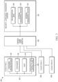
- FIG. 1 illustrates the steps of an embodiment of a method 100 of monitoring control plane event data according to the present teaching.
- a first step 102 cloud provider and/or platform event data is collected.
- This collection step 102 may involve passive receiving and various other methods of receiving and/or retrieving of control plane event data.
- This collection step 102 may involve retrieving the event data, e.g. from a web site, database or other repository.
- a large variety of event data may be collected in the collection step 102 of various embodiments of the method.
- the control plane event data includes, for example, information about changes in infrastructure, adding/removing instances, audit configuration, permission changes, user changes, policy changes, and/or access changes.
- Event data can also include, for example, metrics about cloud resources such as CPU usage, disk I/O, memory, network traffic, application errors, application status, workload status, instance status and other events associated with operation of cloud resources, cloud services, and cloud applications.
- the control plane event data can include the information provided by large public cloud providers, such as Amazon CloudTrail, various Google Cloud APIs, Microsoft Azure and others.
- the control plane event data can be collected in numerous ways.
- the control plane event data can be read from a file.
- the control plane data can also be received from a network.
- the control plane event data can also be requested from a cloud provider by a processor implementing a collection step 102 of the method and/or the control plane data can be sent by the cloud provider to a processor executing a collection step 102 of the method 100.
- the control plane event data can be provided or retrieved at particular times and/or the control plane event data can be provided or retrieved on a near-real-time basis.
- the collection step receives information from a software agent. Also, in some embodiments, the collection step receives information from an operating system.
- a second step 104 the collected data is ingested to form a multiple-source data set.
- Ingested data is data that is brought into the platform that is executing the various steps 100 of the method to form a multiple-source data set that can be further processed in later steps.
- a file may be received by the collector in the collection step 102 and then in the ingestion step 104 the file is read into the processor in the ingestion step 104 and combined with other collected data to produce the multiple-source data set.
- a third step 106 the multiple-source data set is evaluated against a set of rules and policies.
- This evaluation includes, for example, comparing distinct properties, categorizing like properties into a single property, and/or normalizing event data.
- the normalization of the event data is based on the known attributes of the event data that is generated by the distinct control plane of each cloud source.
- the evaluation step 106 results in unifying the collected event data in the multiple-source data set into a common event data format that is compatible with downstream event processing.
- This evaluation process uses key known attributes (format, content, etc.) of control plane events for each specific control plane so that it is possible to find, e.g., common event types and complementary event types, thus allowing conversion of control plane events from multiple sources into common events.
- Some embodiments of the evaluation step 106 result in unifying events in the collected event data by taking events from two sources with similar properties and combining them into a common property.
- This data generated by the third step 106, and used in subsequent processing, is referred to as common event
- a description of instances from two different service provider clouds can be contained in "describe instance” events from each provider in two different formats and/or including different fields and/or different data.
- the multiple-source data resulting from the ingestion step 104 for "describe instance” events from these two sources will contain the "describe instance” events as they are received.
- the evaluation step 106 the multiple-source data is processed such that these two "describe instance” events are rendered into two events in a common structure with the same fields and data is transformed from the original control plane event into this common event structure. This allows the instance descriptions for both clouds to be further processed using the common event structure.
- the common event data is processed in downstream event processing that performs a number of tasks.
- the fourth step 108 may generate alerts, identify policy violations, publish reports, remediate threats and/or modify non-compliant infrastructure into compliant configurations.
- the processing in step four 108 of the common event data results in alerts and or policy violations that enable users to make decisions or to take actions.
- the processing in step four 108 of the common event data can also result in automatic changes to processes and/or configuration or reconfigurations of cloud-based elements to remediate various issues associated with the alert or policy violation.
- the result of the fourth step generates computer processes that enable alerting, reporting and analysis for an end user.
- the results can, for example, produce changes in infrastructure configurations, compliance assurance, establishment of vulnerabilities and threats.
- the processing step four 108 can include a series of processing steps that each produce specific processed data and synthesized information that are derived from the common event data.
- This can be referred to as a pipeline processor architecture, which has the advantage that the processing may be applied in any order, because the output of each pipeline stage that feeds the next stage is the common event data.
- the pipeline processor can, for example, be the pipeline processor disclosed in U.S. Patent Application No. 15/846,780, filed on December 17, 2017 and entitled "System and Method For Cloud-Based Operating System Event and Data Access Monitoring", which is assigned to the present assignee.
- Each stage can also produce refined common event data.
- Various stages of the processing step four 108 can produce, for example, raw event logs, alerts and notifications based on events that satisfy customizable rule sets, vulnerability and exploitation analyses, identification of security threats and vulnerabilities, as well as archives of time-sequenced raw event logs.
- FIG. 2 illustrates a block diagram of an embodiment of a system 200 that monitors control plane event data according to the present teaching.
- Multiple cloud environments, cloud 1 202, cloud 2 204, and cloud 3 206 are connected to collection systems 208, 210.
- Cloud 1 202 and cloud 2 204 are connected to collection system 1 208.
- Cloud 3 is connected to collection system 2 210.
- the collection systems 208, 210 received control plane events from the cloud environments 202, 204, 206.
- the number of cloud environments and collection systems varies.
- the collection systems 208, 210 are connected to a processor 212.
- the processor can take the form of a variety of processor systems.
- the processor 212 can be a single processor or multiple processors.
- the processor 212 can be hardware based or the processor may be a virtual machine processor.
- the processor 212 can also be a cloud-based processor.
- the processor 212 can be a service that can run on a cloud infrastructure.
- the processor 212 is connected to a database 214.
- the database 214 can be a single database or the database can include multiple databases.
- the database(s) 214 can include customer data, infrastructure data, policy data, and/or vulnerability data.
- the database(s) 214 can be private or public databases.
- the database 214 is the National Vulnerability Database.
- the processor 212 is connected to one or more user input/output devices 216.
- the user input/output device(s) 212 can include, for example, a web site, a computer, an application, a management system, or any of a variety of known devices for managing and/or monitoring and/or modifying and/or operating cloud infrastructure.
- FIG. 2 illustrates only a subset of possible elements of the monitoring system of the present teaching. Some embodiments of the monitoring system 200 comprise a large-scale system with numerous other cloud environments, collectors databases, processors and user I/O.
- the processor 212 executes some or all of the steps of the method 100.
- the cloud environments 202, 204, 206 generate control plane event data that is received and/or retrieved in step one 102 by the collectors 208, 210.
- the processor 212 executes in various embodiments all or part of the ingestion step two 104 and/or the evaluation step three 106.
- the processor 212 can also execute step four 108 downstream of the common event data processing and generate alerts and other outputs.
- the processor 212 can also use information retrieved from the database 214 and/or retrieved from any of the results of the ingestion step two 104, the evaluation step three 106, and the alert step 108.
- the processor 212 sends the results of the downstream processing of common event data to the user I/O 216. In some embodiments, the user I/O performs some or all of the processing step four 108.
- one or more of the collectors 208, 210 is a collection processor that is part of processor 212.
- the processor 212 includes an ingestion processor that performs the ingestion step two 104, an evaluation processor that performs the evaluation step three 106, and a processor that executes at least some of the processing in step four 108. These various processors may be the same or different physical and or virtual processors.
- FIG. 3 illustrates an embodiment of a control-plane event monitoring system 300 comprising multiple cloud stacks according to the present teaching.
- a control plane event monitor processor 302 is connected to multiple cloud stacks 304, 306, 308.
- a cloud stack is a set of cloud-based elements including computer resources, services, application and/or functions that are being used and/or controlled by a user.
- a cloud stack represents a cloud environment to the monitoring method and system of the present teaching.
- the user of the cloud stack is an IT organization of a business, but a variety of users, including human and machine-based users are possible.
- Various embodiments of the control-plane event monitoring system 300 connect the control plane event monitor 302 to various numbers of cloud stacks 304, 306, 308.
- One feature of the system and method of the present teaching is that it provides a unified picture of a cloud-based infrastructure of a user, even when the cloud-based elements of that infrastructure reside in different cloud environments.
- a particular application or function, or suite of applications and/or functions are consumed by a user and utilize cloud-based elements in all of the cloud stacks 304, 306, 308.
- the particular application or function, or suite of applications and/or functions are monitored and/or secured.
- the particular application or function, or suite of applications and/or functions is checked for compliance.
- an end system 310 manages the particular application or function, or suite of applications and/or functions.
- An output of the control plane event monitor processor 302 is connected to the end system 310.
- the end system 310 belongs to a customer that is using the cloud-based elements in the cloud stacks 304, 306, 308.
- cloud stack 304 includes a control plane 302 that performs management and control for the services that are provided by the cloud-based elements in the cloud stack 304.
- the control plane 312 performs, for example, security services and management of the authorization and authentication of users accessing applications.
- the control plane 312 can also control run time components and manage their life cycle.
- the control plane 312 can also perform hardware and software load balancing and route service requests to the appropriate cloud-based element.
- the control plane 312 can also manage scheduled tasks and jobs.
- the control plane 312 can store system files associated with services.
- control plane 312 touches many aspects of a given operation that is performed using multiple levels of the cloud stack 304. Therefore, control plane events produces by the control plane 312 provide a rich source of information about the ongoing activities in a cloud stack 304. However, control plane events produced by one cloud stack 304 are different from control plane events produced by a control plane in a different cloud stack. Differences arise, for example, in access methods, format, contents, captured events, sequencing, telemetry, logging, alerting, storing, error handling and other features of events provided by the various control planes.
- cloud stack 304 includes a host 314.
- the host 314 is a physical computer server and/or one or more associated operating systems which run services and applications. That is, a host 314 may be a virtual machine and/or a physical machine.
- a container 316 is a defined unit of software that contains everything necessary to run an application. Multiple containers 316 often run on a host 314. An application can run on multiple containers 316.
- a container orchestrator 318 is used to organize multiple containers.
- Control plane 312 of cloud stack 304 generates control-plane events when any element 312, 314, 316, 318 at any level of the stack is used.
- the elements 312, 314, 316, 318 represent one example of a cloud stack 304. It should be understood that the control-plane event monitor system and method of the present teaching can operate with a variety of other known cloud stacks that include various other different elements. For example, the elements of one cloud stack can be different than the elements of other cloud stacks.
- the end system 310 performs one or more of a number of cloud resource visibility and management functions using the output of the control plane event monitor processor 302.
- the end system 310 can include orchestration applications 320 that arrange and/or coordinate the various automated tasks available from the elements of a cloud environment.
- the end system 310 can also include an external management system 322 that is part of a third-party trusted detection and response partner that helps an organization with management of their cloud-based infrastructure.
- the end system 310 can also include an internal management system 324 that directly manages and controls the cloud-based infrastructure.
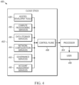
- FIG. 4 illustrates an embodiment of a control-plane event monitoring system 400 comprising a cloud stack that includes multiple cloud-based tools and services according to the present teaching.
- the cloud stack 402 provides inputs to the control-plane event monitoring processor 404 that provides common event data to an end user system 406.
- the cloud stack 402 is just one of multiple possible cloud stacks that can be connected to the control-plane event monitoring processor 404. Referring to FIGS. 3 and 4 , in some embodiments, the cloud stack 402 can be the same as cloud stack 306 and end user system 406 can be the same as end system 310 that were described in connection with FIG. 3 .
- the control plane 408 in the stack 402 provides event information from account management services 410, governance services 412, network configuration services 414, data storage services 416, compute provisioning services 418, and hosted developer tools 420 to the control-plane event monitoring processor 404.
- the control-plane event monitoring processor 404 then generates common event data and provides that event data to the end user system 406.
- the common event data can also be further processed, either by the control-plane event monitoring processor 404 or another processor, to generate alerts and/or to determine violations of policy. These alerts and/or determined policy violations are supplied to an end user system 406.
- the processor 404 generates common event data and the end system 406 generates the alerts and determines policy violations or other outcomes.
- the generated alerts and/or determined policy violations or other processed outcomes can be derived by processing one or more control plane events generated by cloud stack 304 and one or more control plane events generated by cloud stack 402.
- an alert or violation is generated based on information from two different clouds.
- Common event data typically includes various attributes such as an event ID, the event feed, the event type, and the event source.
- common event data include attributes such as region, edge location and/or availability zone associated with the event.
- Common event data can include information, such as IP addresses and other networking parameters.
- common event data can include account numbers, organization identifiers, users and user roles.
- common event data can include event time and other attributes related to timestamps associated with an event. Additional attributes of common event data are associated with the particular type of event.
- control plane event data from two different events representing the same kind of activity provided by a particular control plane is converted into a single event in the common event data.
- a single event from a particular control plane is converted into more than one event in the common event data.
- a common event represents information from more than one control plane event.
- control plane events can be received by the processor 404 from the control plane 408: 1) eventName, "DescribeInstances”; 2) eventName, “GenerateDataKey”; 3) eventName, “GetStackPolicy”; 4) eventName, "DescribeInstanceHealth”; 5) eventName, "AssumeRole”; 6) eventName, "DescribeLifecycleHooks”; 7) eventName, "DescribeVolumes”; 8) eventName, "DescribeSnapshots”; 9) eventName, "ListResourceRecordSets”; and 10) eventName, "DescribeAutoScalingGroup".
- the processor 404 converts an event provided by the control plane 408 into an associated normalized event that is part of the common event data.
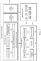
- FIG. 5 illustrates a secured cloud-based environment 500 that runs infrastructure which includes cloud resources from two different cloud service providers 502, 504.
- Cloud resources for the first cloud service provider 502 include compute processors 506, storage 508, database 510 and networking 512.
- cloud resources for the second cloud service provider 504 include compute processors 514, storage 516, database 518 and networking 520.
- Infrastructure for the first cloud service provider 502 includes availability zones 522, regions 524, and edge locations 526.
- infrastructure for the second cloud service provider 504 includes availability zones 528, regions 530, and edge locations 532.
- the secured environment 500 includes containers 534 that run on a host operating system 536, configuration management 538, and event monitoring 540. To provide the secured environment 500, a number of functions are tracked.
- NIST National Vulnerability Data Base (NVD) vulnerabilities 542 are also tracked.
- Configuration management 538 and a control plane event monitor 540 processes are used to provide the secured environment 500.
- the control plane event monitor 540 processes control plane events from the two different cloud service providers 502, 504 and generates common control plane events.
- the control plane event monitor 540 further processes the common control plane events to generate a track of user activity 544, a track of file activity 546 and/or a track of network process connections 548.
- the control plane event monitor 540 further processes the common control plane events using the NIST National Vulnerability Data Base (NVD) vulnerabilities 542 to determine known vulnerabilities that affect the secured environment 500.
- NIST National Vulnerability Data Base (NVD) vulnerabilities 542 to determine known vulnerabilities that affect the secured environment 500.
- the control plane event monitor 540 generates alerts and determines vulnerabilities based on processed common control plane events, including alerts and vulnerabilities that result from events in both of the two different cloud service providers 502, 504. This information can be sent to the configuration management 538 to reconfigure resources based on the information provided by the control plane event monitor 540.
- One feature of the system and methods of the present teaching is that it is able to uncover threats and/or activities in one cloud environment that have an impact on threats and/or activities in another. Additionally, actions monitored in one environment can be assessed as benign within that environment, and yet have important consequences in another environment if the two environments are part of a common cloud infrastructure.
- Known systems monitor only one cloud environment and perform processing on events that are only related to that environment. Such known systems miss activities that cross the environments. For example, changing access levels anywhere in one environment can potentially open a hole in another environment.
- a breach can be detected that is happening in two cloud providers at the same time. Such a breach may not even be detected by monitoring each domain separately, and can be detected and remediated sooner by monitoring and processing common event data from both environments.
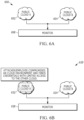
- FIG. 6A illustrates a point in an attack 600 on a cloud infrastructure comprising two cloud-based environments 602, 604 that is detected using an embodiment of the control-plane event monitoring processor 606 according to the present teaching.
- Control planes (not shown) in each of a first public cloud 602 and a second public cloud 604 connect to the control plane event monitoring processor 606.
- the control planes provide event data to the processor 606 from their respective cloud environments 602, 604.
- FIG. 6B illustrates a second point in the attack 620 on the cloud infrastructure comprising two cloud-based environments 622, 624 that is detected using the embodiment of the control-plane event monitoring processor 626 described in connection with FIG. 6A .
- processes in the first cloud environment 622 have evolved as the result of a bad actor, which may be an attacker and/or an employee compromising the cloud-based environment 622 by finding credentials that also provide limited access to the other cloud-based environment 624.
- the control plane in the first cloud environment 622 will generate events associated with this compromise that are provided to a control-plane event monitoring processor 626 that is to updated.
- such events may be, for example, events associated with an access control process in the first cloud environment 622.
- FIG. 6C illustrates a third point in the attack 640 on the cloud infrastructure that comprises two cloud-based environments 642, 644 that are detected using the embodiment of the control-plane event monitoring processor 628 described in connection with FIG. 6A .
- processes in the first cloud environment 642 have evolved as the result of the bad actor now disabling the monitoring on the cloud-based environment 642.
- This disabling activity limits the visibility into the first cloud environment 642 so that known event monitoring schemes, either data plane schemes or control plane schemes that monitor only one environment are ineffective.
- Only control plane events from the second cloud environment 644 that are received by the control-plane event monitoring processor 648 will generate events associated with the attack.
- FIG. 6D illustrates a fourth point in the attack 660 on the cloud infrastructure that comprises two cloud-based environments 662, 664 that is detected using the embodiment of the control-plane event monitoring processor 666 described in connection with FIG. 6A .
- processes in the first and second cloud environments 662, 664 have evolved as the result of the bad actor now attempting exfiltration of data from the second cloud-based environment 664 using the credentials from the first cloud-based environment 662 obtained in attach point two 620 described in connection with FIG. 6B .
- This exfiltration activity will not be discoverable by the control plane events originating from the first cloud-based environment 662 because of the disabling that occurred at the third attach point 630 described in connection with FIG. 6C .
- FIG. 6E illustrates a fifth point in the attack 680 on the cloud infrastructure that comprises two cloud-based environments 682, 684 that is detected using the embodiment of the control-plane event monitoring processing 686 described in connection with FIG. 6A .
- the control-plane event monitoring processor 686 detects the access of the bad actor using credentials gained from the first cloud environment 682 at the second point in the attack 620 described in connection with FIG. 6B .
- the detection of the control-plane event monitoring processor 686 is based on the receiving of control plane events from the second cloud-based environment 684 associated with the exfiltration of data in the second cloud environment 684 and the receiving of control plane events from the first cloud-based environment 682 earlier in the attack sequence.
- control plane events from the two different environments were normalized into a common event format so that they could be processed together so as to correlate, or make a connection between, the credential access in the first cloud and the data exfiltration from the second cloud.
- Known systems would only detect one or the other activity and therefore, not be able to alert managers to the sophisticated cross-cloud-based-environment attack.
- the control-plane event monitoring systems and methods of the present teaching are capable of detecting attacks that involve lateral movement across hosts that are in two different service provider domains.
- Another example attack that can be identified by some embodiments of the cloud-based control-plane-event monitoring system and method of the present teaching is a bad actor gaining access via access keys and persistent permissions.
- some aspects of this attack are described in the context of an Amazon cloud service, but one skilled in the art will appreciate that application of the system and method to other cloud environments is straightforward.
- the bad actor's first step is to gain access using a stolen API keys.
- Common methods attackers use include, for example, stealing from employee laptops via malware or farming from open-source code websites like GitHub where employees accidentally upload their access keys.
- the bad actor confirms that the access key works, the bad actor typically want to ensure that they can regain access, even if someone in security or operations terminates their stolen access key. To do so, they create new keys, assume a role, or use another method to create a way to regain access.
- the system is able to alert based on specific API calls associated with access key management such as, for example, creating, disabling, deleting or listing access keys, retrieving the last used access key, creating users, or listing roles.
- the bad actor Once the bad actor successfully enters the environment via infrastructure APIs, the bad actor typically looks to see whether they have direct access to the resources they need, such as an RDS database or S3 bucket. When they discover they do not, they move on to an alternative route. In this case, the actor launches EC2 instances inside the environment, which are as trusted as any other legitimate host on their network. This scenario is one reason why it is dangerous to assume any network connection coming through a firewall or on a subnet is to be trusted. The bad actor has now established a beachhead in the environment's network, allowing them to perform reconnaissance and scan the local area network that they have breached.
- the cloud-based, control-plane-event monitoring system and method of the present teaching can send alerts on API calls including DescribeKeyPairs, DescribeNetworkAcls, DescribeRouteTables, and RunInstances. If the bad actor wanted to stop control plane logging or delete current event logs, they would use API calls such as DeleteTrail, StopLogging, or Update Trail, all of which would be detected by the monitoring scheme. Also, once the attacker launches the EC2 instance, they can access the metadata associated with the instance with a curl/wget call, which would trigger sending an alert.
- the bad actor can then proceed to move laterally from the initial rogue EC2 instance, scanning and exploiting as they compromise other hosts in the network.
- the EC2 instances are granted IAM permissions when they launch, giving them legitimate access to managed services like S3 or RDS. So after each new host was compromised on the network, the bad actor would check its permissions. This activity would trigger Threat Stack host level alerts, such as unexpected process execution, network activity, suspicious commands, software executing out of /tmp, kernel modules being installed, and more.
- the bad actor can also land on host with sufficient permissions and extract data from RDS. This is accomplished once on a host with the needed IAM permissions. The bad actor then can perform the necessary RDS API calls to access the database with the target data. If the bad actor only steals a small amount of data, these data can be exfiltrated either directly through the terminal or through their chain of compromised hosts possibly avoiding any data loss prevention tools. Attackers aren't always persisting to dive deeper into the host.
- control-pane event monitoring system and method of the present teaching is an important tool to be able to detect these attacks that involve "lateral moves" and activity in a cloud infrastructure that comprises at least two different cloud environments that should be correlated to successfully and/or efficiently detect the attack.
- the evaluation step is able to generate a threat assessment based on processing of events in the common event data set. Threats are assessed based on various metrics. Because the common event data set includes events from multiple cloud environments, the threat assessment spans multiple cloud environments. Metrics include, for example, a frequency of permission changes, a frequency of type of hardware configuration change, and a frequency of user changes. A threat is determined based on a metric, or combination of metrics exceeding a threshold.
- Vulnerabilities can be identified by processing events in the common event data set with data from various published vulnerability databases. For example, the National Vulnerability Database may be used.
- intrusion detection, tampering and software compliance can be evaluated using the events in the common event data set.
- Another feature of the present teaching is that, because it processes events from multiple control planes in multiple cloud environments, it can reduce noise in the resulting common event data set. This results in better outcomes, including higher integrity and/or more efficient identification of vulnerabilities and threats than is possible using event data from prior art single-cloud event monitors.
- Another feature of the present teaching is that it works for applications that utilize containers.
- the explosion of growth in the use of containers and container orchestration, as well as the increased popularity of abstracted infrastructure like managed containers and server-less infrastructure reflects more flexible and efficient environments.
- containers are designed to contain only the base software necessary to execute a particular process or application.
- Containers virtualize access to resources, such as CPU, storage or memory.
- Containers differ from traditional virtualization technology in that they focused on providing a fully-encapsulated environment that is easy to manage for the execution of specific software, process or applications.
- containers are sometimes desirable because they increase compute density by allowing many applications to be deployed on a single virtual server.
- this feature of containers also increases the attack surface. Attackers often compromise a single container and move laterally. That is, one infected container can lead to a chain of events, especially if other containers are configured improperly.
- users rely on a heterogeneous cloud infrastructure that includes varying levels of visibility and complexity. In some cases, users integrate security early into, for example, software development and IT operations (DevOps) processes, and avoid compromise of systems in ways that can be difficult to address retroactively.
- DevOps software development and IT operations
- Monitoring of control plane events offers visibility into container aspects, such as starting and stopping of containers, which can be used in an overall system that monitors cloud-based infrastructure that relies on containers.
- control plane event monitoring can complement other monitoring systems, for example, agent-based monitors that provide information on aspects internal to the container, such as CPU, storage and memory usage.
- Control plane events add valuable information related to the physical hardware in the cloud-based data center infrastructure that supports the containers, for example, rewiring, spin up of new systems, adding of memory, new disks, adding of users, and others.
- Another feature of the system and method for control plane event monitoring of the present teaching is that it provides a cloud-native (i.e. designed specifically for the cloud), platform-independent, comprehensive set of monitoring applications.
- the results of the monitoring method and outputs of the monitoring system of the present teaching can provide synthesized and contextualized data to users relating to events ongoing on their cloud-based infrastructure.
- the results and outputs from the system and method aid remediation of cyber threats across a broad spectrum of activities because it can support a comprehensive set of known security applications.
- Yet another feature of the system of the present teaching is that it utilizes processing assets distributed in a cloud-based computing architecture in a cost-effective manner.
- the system scales in a cost-effective, modular fashion as the monitored information systems grow. This is, at least in part, because the system relies on cloud-based processing resources that can be expanded as the information system demand expands, and reduced when the information system demand wanes.
- the system also easily accommodates addition of new computer infrastructure management, compliance, security threats and new monitoring applications by supporting a configurable and software-application-based monitoring approach. This is in contrasted to known systems where individual point solutions for security and monitoring require specialized, costly, hardware and provide a smaller suite of security and monitoring applications.
Landscapes
- Engineering & Computer Science (AREA)
- Computer Networks & Wireless Communication (AREA)
- Signal Processing (AREA)
- Computer Security & Cryptography (AREA)
- General Engineering & Computer Science (AREA)
- Computer Hardware Design (AREA)
- Theoretical Computer Science (AREA)
- Software Systems (AREA)
- Computing Systems (AREA)
- Physics & Mathematics (AREA)
- General Physics & Mathematics (AREA)
- Health & Medical Sciences (AREA)
- Bioethics (AREA)
- General Health & Medical Sciences (AREA)
- Environmental & Geological Engineering (AREA)
- Data Mining & Analysis (AREA)
- Automation & Control Theory (AREA)
- Business, Economics & Management (AREA)
- General Business, Economics & Management (AREA)
- Quality & Reliability (AREA)
- Databases & Information Systems (AREA)
- Debugging And Monitoring (AREA)
- Computer And Data Communications (AREA)
- Testing And Monitoring For Control Systems (AREA)
Description
- The section headings used herein are for organizational purposes only and should not to be construed as limiting the subject matter described in the present application in any way.
- The movement of data and software applications to the cloud has fundamentally changed the way that computer systems provide software applications and services to users. For example, the network edge of traditional enterprise networks has been replaced by a virtual perimeter, thus changing the way that computers process information and the way that data are accessed by computers. As a result, the ingress and egress point where hardware security appliances and network visibility devices have traditionally been deployed has been eliminated. Not only is the basic processing architecture different in the cloud, but the scale and growth models of processes, applications, and services are also different in the cloud. For example, cloud-based computer system resources can grow and shrink on very rapid time scales. Also, cloud-based computer systems can be highly distributed so tracking and correctly sequencing events is significantly more challenging. Furthermore, security and vulnerability threat models are also necessarily different in cloud-based computer systems as compared to fixed-infrastructure enterprise networks. Consequently, traditional methods and systems that monitor and protect networked information and systems on the cloud are no longer adequate.
-
US 2017/295199 A1 discloses systems and methods for cloud security monitoring and threat intelligence.US 2018/027006 A1 discloses methods and systems including a cyber intelligence system, a unified application firewall, and a cloud security fabric.US 2017/126469 A1 discloses a service control system that manages a set of containers operating within one or more computing hosts. - According to a first aspect, there is provided a method for cloud-based, control-plane-event monitoring as defined in
claim 1. - According to a second aspect, there is provided a system for cloud-based, control-plane-event monitoring as defined in claim 10.
- The present teaching, in accordance with preferred and exemplary embodiments, together with further advantages thereof, is more particularly described in the following detailed description, taken in conjunction with the accompanying drawings. The skilled person in the art will understand that the drawings, described below, are for illustration purposes only. The drawings are not necessarily to scale, emphasis instead generally being placed upon illustrating principles of the teaching. The drawings are not intended to limit the scope of the Applicant's teaching in any way.
-
FIG. 1 illustrates the steps of an embodiment of a method of monitoring control plane event data according to the present teaching. -
FIG. 2 illustrates a block diagram of an embodiment of a system that monitors control plane event data according to the present teaching. -
FIG. 3 illustrates an embodiment of a control-plane event monitoring system comprising multiple cloud stacks according to the present teaching. -
FIG. 4 illustrates an embodiment of a control-plane event monitoring system comprising a cloud stack that includes multiple cloud-based tools and services according to the present teaching. -
FIG. 5 illustrates a secured cloud-based environment that runs infrastructure that includes cloud resources from two different cloud service providers. -
FIG. 6A illustrates a point in an attack on a cloud infrastructure comprising two cloud-based environments that is detected using an embodiment of the control-plane event monitoring processor according to the present teaching. -
FIG. 6B illustrates a second point in the attack on the cloud infrastructure comprising two cloud-based environments that is detected using the embodiment of the control-plane event monitoring processor described in connection withFIG. 6A . -
FIG. 6C illustrates a third point in the attack on the cloud infrastructure that comprises two cloud-based environments that is detected using the embodiment of the control-plane event monitoring processor described in connection withFIG. 6A . -
FIG. 6D illustrates a fourth point in the attack on the cloud infrastructure that comprises two cloud-based environments that is detected using the embodiment of the control-plane event monitoring processor described in connection withFIG. 6A . -
FIG. 6E illustrates a fifth point in the attack on the cloud infrastructure that comprises two cloud-based environments that is detected using and the embodiment of the control-plane event monitoring processor described in connection withFIG. 6A . - The present teaching will now be described in more detail with reference to exemplary embodiments thereof as shown in the accompanying drawings. While the present teachings are described in conjunction with various embodiments and examples, it is not intended that the present teachings be limited to such embodiments. On the contrary, the present teachings encompass various alternatives, modifications and equivalents, as will be appreciated by those of skill in the art. Those of ordinary skill in the art having access to the teaching herein will recognize additional implementations, modifications, and embodiments, as well as other fields of use, which are within the scope of the present disclosure as described herein.
- Reference in the specification to "one embodiment" or "an embodiment" means that a particular feature, structure, or characteristic described in connection with the embodiment is included in at least one embodiment of the teaching. The appearances of the phrase "in one embodiment" in various places in the specification are not necessarily all referring to the same embodiment.
- It should be understood that the individual steps of the methods of the present teachings can be performed in any order and/or simultaneously as long as the teaching remains operable. Furthermore, it should be understood that the apparatus and methods of the present teachings can include any number or all of the described embodiments as long as the teaching remains operable.
- The growing reliance on cloud infrastructure means many organizations utilize cloud resources from multiple cloud providers to make up their cloud-based infrastructure. Thus, the integrity of a computing system and services that run on the cloud-based infrastructure must be ensured even in cases where the infrastructure includes multiple service providers.
- Furthermore, it is not sufficient to allocate computer security resources only where sensitive data resides and leave other parts of the infrastructure unsecured or monitored. This approach overlooks less obvious routes to sensitive data that can be exploited by a bad actor. Monitoring the entire infrastructure increases the chances of detecting an attack early and decreases the time to investigate, especially as detecting reconnaissance at the edge of a system becomes increasingly difficult. Because attackers aren't always looking for large amounts of data, rather often they are looking for a small amount of very specific data, it is possible for these threats to go undetected. Data can be extracted by a bad actor by copying and pasting or even taking a screenshot. Consequently, it's important to add multiple layers of monitoring and subsequent threat detection, including monitoring access to the data within a file and not just changes to the file itself.
- Thus, new monitoring and security systems and methods are required for the cloud, which are built specifically for cloud-based information systems. Many applications using the cloud, including credit card processing, financial transactions, corporate governance, content delivery, health care, and enterprise network security require monitoring and protecting digital data as well as assurance regarding the integrity of processing that data. Compliance with regulations, reporting and standards, such as Payment Card Industry Data Security Standard (PCI DSS), Health Insurance Portability and Accountability Act (HIPAA), Service Organization Controls (SOC), International Organization for Standardization standards for information security management (ISO 27001), Digital Rights Management (DRM), and Sarbanes-Oxley (SOX) all demand careful and traceable accountability of data as well as convenient data processing and access to data.
- Some embodiments of the cloud-based control-plane-event monitoring system and method according to the present teaching are used to monitor cloud, multi-cloud, hybrid and containerized infrastructure for intrusions, anomalies, vulnerabilities, trends, misconfigurations and other items across the host and infrastructure control plane. One key feature is that the system can monitor a common threat that is operating across or persisting on two different cloud environments that are part of the monitored cloud-based infrastructure. Detection of such multi-cloud operation is not possible on known monitoring systems because, for one thing, the events and methods of reporting of various events by the different infrastructures is not uniform. As such, it is not possible to directly correlate, process, compare and/or categorize events received from different cloud environments to generate conclusive policy violations or alert triggers. The method and systems of the present teaching collects, ingests and normalizes received control plane events from more than one cloud environment so that policy violation and/or alerts can be generated. The method and system of the present teaching can also produce actions including changes to processes and reconfigurations of infrastructure, which are based on the policy violations and/or alerts.
- Thus, it is highly desirable for cloud-based systems to monitor methods and systems that are capable of monitoring a cloud-based infrastructure that extends across multiple domains including, for example, infrastructure that extends across multiple service providers and/or infrastructure that includes different platforms within a single service provider.
- A domain as used herein is a set of cloud-based elements that share a common control plane. Monitoring systems can provide a variety of functions including, for example, tracking the time sequence of events, tracking users, and tracking access to file systems based on roles and/or individual users. Monitoring systems can also provide tracking instances of particular applications, systems, or processes as they migrate across virtual resources in the cloud.
- The term "cloud-based element" as used herein can refer to hardware, software and combinations of hardware and software used in the cloud. For example a cloud-based element can refer to software that is running on cloud-based hardware. A cloud-based element can also refer to a hardware device that is located in the cloud. A cloud-based element can also refer to a virtual machine or other virtual computing operation. A cloud-based element can also refer to both software and the hardware-based computing device on which the software is running. Software, as used herein refers to a collection of executable code that provides processes, applications and/or services. In addition, cloud-based elements as used herein can be various services and/or platforms that run on the cloud.
- One aspect of the present teaching is a cloud-native monitoring suite of applications that can run on any computing platform, including, for example, virtual machines, servers, desktop, laptop and handheld devices. The computing platforms that execute the system and method of the present teaching may be dedicated or shared.
- Another aspect of the cloud-based control-plane event monitoring system of the present teaching is that it can transform control plane events from several public cloud providers into a common format, thereby enabling the evaluation of events according to pre-defined rulesets. To support this evaluation, the cloud-based control-plane event monitoring system of the present teaching transforms control plane events from several services within a particular cloud, or across multiple public cloud providers into a common format, thereby enabling the evaluation of events according to pre-defined rulesets.
- Another aspect of the cloud-based control-plane event monitoring system of the present teaching is that is can transform control plane events from cloud-based infrastructure with different control planes. These cloud-based infrastructures can include, for example, public clouds, private clouds, and hybrid (public and private) cloud infrastructures. The transformation of control plane events from different cloud environments allows for identification of a variety of important conditions related to the infrastructure including, for example, vulnerabilities and threats, security events, misconfigurations, unauthorized accesses, policy violations and other conditions that occur within and across the multiple monitored cloud environments.
- The computer industry has recently observed bad actors using increasingly sophisticated malicious techniques on the public cloud. The threats generated by these bad actors leverage the unique characteristics of cloud services and deployment models to launch or hide their breaches. In simple attacks, for example, bad actors steal access keys and look for a direct path to sensitive data or valuable resources, such as an open S3 bucket or the ability to launch a new EC2 to mine crypto currency. In more sophisticated attacks, the bad actors present threats that incorporate multiple steps and can traverse the target's infrastructure. These threats can move back-and-forth from the cloud infrastructure control plane to the host. Threats can also migrate from infrastructure used by a target that is managed by one cloud provider (a first cloud environment) to infrastructure used by the target that is managed by a second cloud provider (a second cloud environment). In some cases, many different cloud environments can be involved. Examples of different cloud environments include Amazon AWS cloud, Microsoft Azure cloud, Google cloud, etc. Private and public/private clouds may also be cloud environments that are part of an attack.
- It should be understood that a distinct cloud environment is one in which a distinct control plane is used to manage and control the cloud-based elements within the cloud environment. Thus, two different cloud environments can include two sets of cloud-based resources that reside in two different service providers and/or two different cloud environments that include two sets of cloud-based resources that each reside in a different service domain that is owned by the same service provider.
- Many service providers offer cloud-based elements that include an array of compute, storage, database, networking, and cloud migration services. In addition, a variety of cloud-based elements, such as tools and applications like search, load balancing, and software development tools are available. Amazon Web Services (AWS) offers multiple services including elastic compute cloud (EC2), relational database service (RDS), simple storage service (S3). Amazon also offers services, such as identity and access management (IAM). Likewise, Google offers cloud services, sometimes referred to as Google Cloud. These and other service providers offer a variety of cloud storage services, including managed databases, object, block, and file storage.
- Many of these services, or collections of these services, include a control plane that generates events related to actions taken on or within the particular service, even if they are run by the same service provider. In other cases, a control plane surrounds a suite of resources and services. As such, a particular cloud environment is one in which a separate control plane is used for the service, even if the service is offered by a common service provider. Services that run on different service providers, such as Amazon, Google, Microsoft and others, use separate control planes, and therefore are also considered different cloud environments. An advantage of using control plane events as part of a system and method of monitoring infrastructure is that control plane events typically include both data plane events and management events. As such, control plane events provide a large amount of information about a cloud-based environment and how and why the hardware, software and services of the cloud-based environment changes over time.
- A complication in monitoring multiple cloud environments is that each cloud provider utilizes different and varying data formats, information content, and attributes for control plane events. Each cloud provider can also utilize different export methods for control plane events. These differences make it difficult to unify and compare changes of infrastructure across different cloud providers in a uniform manner. Likewise, different platforms within a particular cloud provider can operate using a different control plane and/or can comprise events that are encapsulated in varying data formats and export methods. Thus, these different cloud environments require that the events provided by their control planes be ingested and normalized in order to present a unified picture of what is happening on the infrastructure.
- The control-plane event monitoring system and method of the present teaching allows organizations to monitor and act on infrastructure activity for a cloud-based infrastructure that extends across multiple cloud providers and platforms from a single viewpoint. In some embodiments, each cloud provider and/or platform monitors and maintains their user's infrastructure in a proprietary manner. Also, each cloud provider and/or platform lets users receive and/or view the infrastructure and associated events in a variety of ways. For example, users can view various consoles, web access, and/or APIs. When an end user is maintaining a cloud-based infrastructure that includes cloud elements from multiple cloud providers and/or cloud elements from multiple platforms, the viewing of the infrastructure involves using several disparate tools to view and monitor a cross provider and, in some cases, cross-platform infrastructure. The control-plane event monitoring system and method of the present teaching can eliminate the need for the multiple views.
- One feature of the control plane event monitoring system and method of the present teaching is that it unifies disparate monitoring of known systems into a common view that is able to provide outputs that are useful to a user, including generating alert outputs and determining policy violations as output. That is, various embodiments of the control plane event monitoring system and method of the present teaching unify cloud-based event collection from different control planes associated with different cloud service providers and/or cloud platforms so that they can be processed to generate event-based alerts and policy violations that cross these service providers and/or platforms.
-
FIG. 1 illustrates the steps of an embodiment of amethod 100 of monitoring control plane event data according to the present teaching. In afirst step 102, cloud provider and/or platform event data is collected. Thiscollection step 102 may involve passive receiving and various other methods of receiving and/or retrieving of control plane event data. Thiscollection step 102 may involve retrieving the event data, e.g. from a web site, database or other repository. A large variety of event data may be collected in thecollection step 102 of various embodiments of the method. The control plane event data includes, for example, information about changes in infrastructure, adding/removing instances, audit configuration, permission changes, user changes, policy changes, and/or access changes. Event data can also include, for example, metrics about cloud resources such as CPU usage, disk I/O, memory, network traffic, application errors, application status, workload status, instance status and other events associated with operation of cloud resources, cloud services, and cloud applications. The control plane event data can include the information provided by large public cloud providers, such as Amazon CloudTrail, various Google Cloud APIs, Microsoft Azure and others. - The control plane event data can be collected in numerous ways. For example, the control plane event data can be read from a file. The control plane data can also be received from a network. The control plane event data can also be requested from a cloud provider by a processor implementing a
collection step 102 of the method and/or the control plane data can be sent by the cloud provider to a processor executing acollection step 102 of themethod 100. The control plane event data can be provided or retrieved at particular times and/or the control plane event data can be provided or retrieved on a near-real-time basis. In some embodiments, the collection step receives information from a software agent. Also, in some embodiments, the collection step receives information from an operating system. - In a
second step 104, the collected data is ingested to form a multiple-source data set. Ingested data is data that is brought into the platform that is executing thevarious steps 100 of the method to form a multiple-source data set that can be further processed in later steps. For example, a file may be received by the collector in thecollection step 102 and then in theingestion step 104 the file is read into the processor in theingestion step 104 and combined with other collected data to produce the multiple-source data set. - In a
third step 106, the multiple-source data set is evaluated against a set of rules and policies. This evaluation includes, for example, comparing distinct properties, categorizing like properties into a single property, and/or normalizing event data. The normalization of the event data is based on the known attributes of the event data that is generated by the distinct control plane of each cloud source. Theevaluation step 106 results in unifying the collected event data in the multiple-source data set into a common event data format that is compatible with downstream event processing. This evaluation process uses key known attributes (format, content, etc.) of control plane events for each specific control plane so that it is possible to find, e.g., common event types and complementary event types, thus allowing conversion of control plane events from multiple sources into common events. Some embodiments of theevaluation step 106 result in unifying events in the collected event data by taking events from two sources with similar properties and combining them into a common property. This data generated by thethird step 106, and used in subsequent processing, is referred to as common event data. - For example, a description of instances from two different service provider clouds can be contained in "describe instance" events from each provider in two different formats and/or including different fields and/or different data. The multiple-source data resulting from the
ingestion step 104 for "describe instance" events from these two sources will contain the "describe instance" events as they are received. In theevaluation step 106, the multiple-source data is processed such that these two "describe instance" events are rendered into two events in a common structure with the same fields and data is transformed from the original control plane event into this common event structure. This allows the instance descriptions for both clouds to be further processed using the common event structure. - In a
fourth step 108, the common event data is processed in downstream event processing that performs a number of tasks. For example, thefourth step 108 may generate alerts, identify policy violations, publish reports, remediate threats and/or modify non-compliant infrastructure into compliant configurations. The processing in step four 108 of the common event data results in alerts and or policy violations that enable users to make decisions or to take actions. The processing in step four 108 of the common event data can also result in automatic changes to processes and/or configuration or reconfigurations of cloud-based elements to remediate various issues associated with the alert or policy violation. - The result of the fourth step generates computer processes that enable alerting, reporting and analysis for an end user. The results can, for example, produce changes in infrastructure configurations, compliance assurance, establishment of vulnerabilities and threats. The processing step four 108 can include a series of processing steps that each produce specific processed data and synthesized information that are derived from the common event data. This can be referred to as a pipeline processor architecture, which has the advantage that the processing may be applied in any order, because the output of each pipeline stage that feeds the next stage is the common event data. The pipeline processor can, for example, be the pipeline processor disclosed in
U.S. Patent Application No. 15/846,780, filed on December 17, 2017 -
FIG. 2 illustrates a block diagram of an embodiment of asystem 200 that monitors control plane event data according to the present teaching. Multiple cloud environments,cloud 1 202,cloud 2 204, andcloud 3 206 are connected tocollection systems Cloud 1 202 andcloud 2 204 are connected tocollection system 1 208.Cloud 3 is connected tocollection system 2 210. Thecollection systems cloud environments - The
collection systems processor 212. The processor can take the form of a variety of processor systems. For example, theprocessor 212 can be a single processor or multiple processors. Theprocessor 212 can be hardware based or the processor may be a virtual machine processor. Theprocessor 212 can also be a cloud-based processor. For example, theprocessor 212 can be a service that can run on a cloud infrastructure. In some embodiments, theprocessor 212 is connected to adatabase 214. Thedatabase 214 can be a single database or the database can include multiple databases. The database(s) 214 can include customer data, infrastructure data, policy data, and/or vulnerability data. The database(s) 214 can be private or public databases. In some embodiments, thedatabase 214 is the National Vulnerability Database. - The
processor 212 is connected to one or more user input/output devices 216. The user input/output device(s) 212 can include, for example, a web site, a computer, an application, a management system, or any of a variety of known devices for managing and/or monitoring and/or modifying and/or operating cloud infrastructure. For simplicity,FIG. 2 illustrates only a subset of possible elements of the monitoring system of the present teaching. Some embodiments of themonitoring system 200 comprise a large-scale system with numerous other cloud environments, collectors databases, processors and user I/O. - Referring to both
FIGS. 1 and 2 , theprocessor 212 executes some or all of the steps of themethod 100. Thecloud environments collectors processor 212 executes in various embodiments all or part of the ingestion step two 104 and/or the evaluation step three 106. Theprocessor 212 can also execute step four 108 downstream of the common event data processing and generate alerts and other outputs. Theprocessor 212 can also use information retrieved from thedatabase 214 and/or retrieved from any of the results of the ingestion step two 104, the evaluation step three 106, and thealert step 108. Theprocessor 212 sends the results of the downstream processing of common event data to the user I/O 216. In some embodiments, the user I/O performs some or all of the processing step four 108. - In some embodiments, one or more of the
collectors processor 212. In some embodiments, theprocessor 212 includes an ingestion processor that performs the ingestion step two 104, an evaluation processor that performs the evaluation step three 106, and a processor that executes at least some of the processing in step four 108. These various processors may be the same or different physical and or virtual processors. -
FIG. 3 illustrates an embodiment of a control-planeevent monitoring system 300 comprising multiple cloud stacks according to the present teaching. A control planeevent monitor processor 302 is connected tomultiple cloud stacks event monitoring system 300 connect the control plane event monitor 302 to various numbers ofcloud stacks - One feature of the system and method of the present teaching is that it provides a unified picture of a cloud-based infrastructure of a user, even when the cloud-based elements of that infrastructure reside in different cloud environments. Thus, in some embodiments, a particular application or function, or suite of applications and/or functions, are consumed by a user and utilize cloud-based elements in all of the cloud stacks 304, 306, 308. In various embodiments, the particular application or function, or suite of applications and/or functions, are monitored and/or secured. Also, in various embodiments, the particular application or function, or suite of applications and/or functions is checked for compliance. Also, in various embodiments, an
end system 310 manages the particular application or function, or suite of applications and/or functions. - An output of the control plane
event monitor processor 302 is connected to theend system 310. In some embodiments, theend system 310 belongs to a customer that is using the cloud-based elements in the cloud stacks 304, 306, 308. As an example,cloud stack 304 includes acontrol plane 302 that performs management and control for the services that are provided by the cloud-based elements in thecloud stack 304. Thecontrol plane 312 performs, for example, security services and management of the authorization and authentication of users accessing applications. Thecontrol plane 312 can also control run time components and manage their life cycle. Thecontrol plane 312 can also perform hardware and software load balancing and route service requests to the appropriate cloud-based element. Thecontrol plane 312 can also manage scheduled tasks and jobs. In addition, thecontrol plane 312 can store system files associated with services. - One feature of the
control plane 312 described herein is that it touches many aspects of a given operation that is performed using multiple levels of thecloud stack 304. Therefore, control plane events produces by thecontrol plane 312 provide a rich source of information about the ongoing activities in acloud stack 304. However, control plane events produced by onecloud stack 304 are different from control plane events produced by a control plane in a different cloud stack. Differences arise, for example, in access methods, format, contents, captured events, sequencing, telemetry, logging, alerting, storing, error handling and other features of events provided by the various control planes. - As an example,
cloud stack 304 includes ahost 314. Thehost 314 is a physical computer server and/or one or more associated operating systems which run services and applications. That is, ahost 314 may be a virtual machine and/or a physical machine. Acontainer 316 is a defined unit of software that contains everything necessary to run an application.Multiple containers 316 often run on ahost 314. An application can run onmultiple containers 316. Acontainer orchestrator 318 is used to organize multiple containers.Control plane 312 ofcloud stack 304 generates control-plane events when anyelement elements cloud stack 304. It should be understood that the control-plane event monitor system and method of the present teaching can operate with a variety of other known cloud stacks that include various other different elements. For example, the elements of one cloud stack can be different than the elements of other cloud stacks. - The
end system 310 performs one or more of a number of cloud resource visibility and management functions using the output of the control planeevent monitor processor 302. For example, theend system 310 can includeorchestration applications 320 that arrange and/or coordinate the various automated tasks available from the elements of a cloud environment. Theend system 310 can also include anexternal management system 322 that is part of a third-party trusted detection and response partner that helps an organization with management of their cloud-based infrastructure. Theend system 310 can also include aninternal management system 324 that directly manages and controls the cloud-based infrastructure. -
FIG. 4 illustrates an embodiment of a control-planeevent monitoring system 400 comprising a cloud stack that includes multiple cloud-based tools and services according to the present teaching. Thecloud stack 402 provides inputs to the control-planeevent monitoring processor 404 that provides common event data to anend user system 406. Thecloud stack 402 is just one of multiple possible cloud stacks that can be connected to the control-planeevent monitoring processor 404. Referring toFIGS. 3 and4 , in some embodiments, thecloud stack 402 can be the same ascloud stack 306 andend user system 406 can be the same asend system 310 that were described in connection withFIG. 3 . - The
control plane 408 in thestack 402 provides event information fromaccount management services 410,governance services 412, network configuration services 414,data storage services 416, computeprovisioning services 418, and hosteddeveloper tools 420 to the control-planeevent monitoring processor 404. The control-planeevent monitoring processor 404 then generates common event data and provides that event data to theend user system 406. The common event data can also be further processed, either by the control-planeevent monitoring processor 404 or another processor, to generate alerts and/or to determine violations of policy. These alerts and/or determined policy violations are supplied to anend user system 406. In some embodiments, theprocessor 404 generates common event data and theend system 406 generates the alerts and determines policy violations or other outcomes. - Referring to
FIGS. 3 and4 , the generated alerts and/or determined policy violations or other processed outcomes can be derived by processing one or more control plane events generated bycloud stack 304 and one or more control plane events generated bycloud stack 402. Thus, an alert or violation is generated based on information from two different clouds. - As described herein, the normalization of control plane events produces common event data from multiple different control planes. Common event data typically includes various attributes such as an event ID, the event feed, the event type, and the event source. In some embodiments common event data include attributes such as region, edge location and/or availability zone associated with the event. Common event data can include information, such as IP addresses and other networking parameters. Also, common event data can include account numbers, organization identifiers, users and user roles. Also, common event data can include event time and other attributes related to timestamps associated with an event. Additional attributes of common event data are associated with the particular type of event.
- In some embodiments of the method of the present teaching, control plane event data from two different events representing the same kind of activity provided by a particular control plane is converted into a single event in the common event data. In some cases, a single event from a particular control plane is converted into more than one event in the common event data. In some methods, a common event represents information from more than one control plane event.
- For example, referring to
FIG. 4 , the following control plane events can be received by theprocessor 404 from the control plane 408: 1) eventName, "DescribeInstances"; 2) eventName, "GenerateDataKey"; 3) eventName, "GetStackPolicy"; 4) eventName, "DescribeInstanceHealth"; 5) eventName, "AssumeRole"; 6) eventName, "DescribeLifecycleHooks"; 7) eventName, "DescribeVolumes"; 8) eventName, "DescribeSnapshots"; 9) eventName, "ListResourceRecordSets"; and 10) eventName, "DescribeAutoScalingGroup". For each of these named events, theprocessor 404 converts an event provided by thecontrol plane 408 into an associated normalized event that is part of the common event data. These events are described in the context of AWS CloudTrail, but extension to other control planes is straightforward. -
FIG. 5 illustrates a secured cloud-based environment 500 that runs infrastructure which includes cloud resources from two differentcloud service providers cloud service provider 502 includecompute processors 506, storage 508,database 510 andnetworking 512. Similarly, cloud resources for the secondcloud service provider 504 includecompute processors 514,storage 516,database 518 andnetworking 520. Infrastructure for the firstcloud service provider 502 includesavailability zones 522,regions 524, andedge locations 526. Similarly, infrastructure for the secondcloud service provider 504 includesavailability zones 528,regions 530, andedge locations 532. The secured environment 500 includescontainers 534 that run on ahost operating system 536,configuration management 538, andevent monitoring 540. To provide the secured environment 500, a number of functions are tracked. This includes, for example,user activity 544,file activity 546 andnetwork process connections 548. The NIST National Vulnerability Data Base (NVD)vulnerabilities 542 are also tracked.Configuration management 538 and a control plane event monitor 540 processes are used to provide the secured environment 500. The control plane event monitor 540 processes control plane events from the two differentcloud service providers user activity 544, a track offile activity 546 and/or a track ofnetwork process connections 548. The control plane event monitor 540 further processes the common control plane events using the NIST National Vulnerability Data Base (NVD)vulnerabilities 542 to determine known vulnerabilities that affect the secured environment 500. The control plane event monitor 540 generates alerts and determines vulnerabilities based on processed common control plane events, including alerts and vulnerabilities that result from events in both of the two differentcloud service providers configuration management 538 to reconfigure resources based on the information provided by the controlplane event monitor 540. - One feature of the system and methods of the present teaching is that it is able to uncover threats and/or activities in one cloud environment that have an impact on threats and/or activities in another. Additionally, actions monitored in one environment can be assessed as benign within that environment, and yet have important consequences in another environment if the two environments are part of a common cloud infrastructure. Known systems monitor only one cloud environment and perform processing on events that are only related to that environment. Such known systems miss activities that cross the environments. For example, changing access levels anywhere in one environment can potentially open a hole in another environment. In addition, a breach can be detected that is happening in two cloud providers at the same time. Such a breach may not even be detected by monitoring each domain separately, and can be detected and remediated sooner by monitoring and processing common event data from both environments.
-
FIG. 6A illustrates a point in anattack 600 on a cloud infrastructure comprising two cloud-basedenvironments event monitoring processor 606 according to the present teaching. Control planes (not shown) in each of a firstpublic cloud 602 and a secondpublic cloud 604 connect to the control planeevent monitoring processor 606. The control planes provide event data to theprocessor 606 from theirrespective cloud environments -
FIG. 6B illustrates a second point in theattack 620 on the cloud infrastructure comprising two cloud-basedenvironments event monitoring processor 626 described in connection withFIG. 6A . At thissecond point 620 processes in thefirst cloud environment 622 have evolved as the result of a bad actor, which may be an attacker and/or an employee compromising the cloud-basedenvironment 622 by finding credentials that also provide limited access to the other cloud-basedenvironment 624. The control plane in thefirst cloud environment 622 will generate events associated with this compromise that are provided to a control-planeevent monitoring processor 626 that is to updated. In some embodiments, such events may be, for example, events associated with an access control process in thefirst cloud environment 622. -
FIG. 6C illustrates a third point in theattack 640 on the cloud infrastructure that comprises two cloud-basedenvironments FIG. 6A . At thisthird point 640, processes in thefirst cloud environment 642 have evolved as the result of the bad actor now disabling the monitoring on the cloud-basedenvironment 642. This disabling activity limits the visibility into thefirst cloud environment 642 so that known event monitoring schemes, either data plane schemes or control plane schemes that monitor only one environment are ineffective. Now, only control plane events from thesecond cloud environment 644 that are received by the control-plane event monitoring processor 648 will generate events associated with the attack. -
FIG. 6D illustrates a fourth point in theattack 660 on the cloud infrastructure that comprises two cloud-basedenvironments event monitoring processor 666 described in connection withFIG. 6A . At thisfourth point 660, processes in the first andsecond cloud environments environment 664 using the credentials from the first cloud-basedenvironment 662 obtained in attach point two 620 described in connection withFIG. 6B . This exfiltration activity will not be discoverable by the control plane events originating from the first cloud-basedenvironment 662 because of the disabling that occurred at the third attach point 630 described in connection withFIG. 6C . -
FIG. 6E illustrates a fifth point in theattack 680 on the cloud infrastructure that comprises two cloud-basedenvironments event monitoring processing 686 described in connection withFIG. 6A . At thisfifth point 680, the control-planeevent monitoring processor 686 detects the access of the bad actor using credentials gained from thefirst cloud environment 682 at the second point in theattack 620 described in connection withFIG. 6B . The detection of the control-planeevent monitoring processor 686 is based on the receiving of control plane events from the second cloud-basedenvironment 684 associated with the exfiltration of data in thesecond cloud environment 684 and the receiving of control plane events from the first cloud-basedenvironment 682 earlier in the attack sequence. The control plane events from the two different environments were normalized into a common event format so that they could be processed together so as to correlate, or make a connection between, the credential access in the first cloud and the data exfiltration from the second cloud. Known systems would only detect one or the other activity and therefore, not be able to alert managers to the sophisticated cross-cloud-based-environment attack. Thus, the control-plane event monitoring systems and methods of the present teaching are capable of detecting attacks that involve lateral movement across hosts that are in two different service provider domains. - Another example attack that can be identified by some embodiments of the cloud-based control-plane-event monitoring system and method of the present teaching is a bad actor gaining access via access keys and persistent permissions. By way of example, some aspects of this attack are described in the context of an Amazon cloud service, but one skilled in the art will appreciate that application of the system and method to other cloud environments is straightforward. In attacks of this nature, ranging from rudimentary to sophisticated, the bad actor's first step is to gain access using a stolen API keys. Common methods attackers use include, for example, stealing from employee laptops via malware or farming from open-source code websites like GitHub where employees accidentally upload their access keys. Once the bad actor confirms that the access key works, the bad actor typically want to ensure that they can regain access, even if someone in security or operations terminates their stolen access key. To do so, they create new keys, assume a role, or use another method to create a way to regain access. Through collection and ingestion of control plane event data and subsequent processing as described herein, the system is able to alert based on specific API calls associated with access key management such as, for example, creating, disabling, deleting or listing access keys, retrieving the last used access key, creating users, or listing roles.
- Once the bad actor successfully enters the environment via infrastructure APIs, the bad actor typically looks to see whether they have direct access to the resources they need, such as an RDS database or S3 bucket. When they discover they do not, they move on to an alternative route. In this case, the actor launches EC2 instances inside the environment, which are as trusted as any other legitimate host on their network. This scenario is one reason why it is dangerous to assume any network connection coming through a firewall or on a subnet is to be trusted. The bad actor has now established a beachhead in the environment's network, allowing them to perform reconnaissance and scan the local area network that they have breached. In these cases, the cloud-based, control-plane-event monitoring system and method of the present teaching can send alerts on API calls including DescribeKeyPairs, DescribeNetworkAcls, DescribeRouteTables, and RunInstances. If the bad actor wanted to stop control plane logging or delete current event logs, they would use API calls such as DeleteTrail, StopLogging, or Update Trail, all of which would be detected by the monitoring scheme. Also, once the attacker launches the EC2 instance, they can access the metadata associated with the instance with a curl/wget call, which would trigger sending an alert.
- The bad actor can then proceed to move laterally from the initial rogue EC2 instance, scanning and exploiting as they compromise other hosts in the network. The EC2 instances are granted IAM permissions when they launch, giving them legitimate access to managed services like S3 or RDS. So after each new host was compromised on the network, the bad actor would check its permissions. This activity would trigger Threat Stack host level alerts, such as unexpected process execution, network activity, suspicious commands, software executing out of /tmp, kernel modules being installed, and more.
- The bad actor can also land on host with sufficient permissions and extract data from RDS. This is accomplished once on a host with the needed IAM permissions. The bad actor then can perform the necessary RDS API calls to access the database with the target data. If the bad actor only steals a small amount of data, these data can be exfiltrated either directly through the terminal or through their chain of compromised hosts possibly avoiding any data loss prevention tools. Attackers aren't always persisting to dive deeper into the host.
- One reason why the type of lateral movement in this attack is often hard to detect is that most known host-level security monitoring techniques assume a bad actor will want to persist deeper into the host and escalate privileges on it. Thus, these known monitoring systems create strong controls for these types of behavior on top of decades of Linux/Unix experience. Instead, however, the bad actors were attempting to move off the host layer and back into the infrastructure control plane, an activity that most blue teams are not looking for and that never requires them to become root. As such, the control-pane event monitoring system and method of the present teaching is an important tool to be able to detect these attacks that involve "lateral moves" and activity in a cloud infrastructure that comprises at least two different cloud environments that should be correlated to successfully and/or efficiently detect the attack.
- One feature of the present teaching is that the evaluation step is able to generate a threat assessment based on processing of events in the common event data set. Threats are assessed based on various metrics. Because the common event data set includes events from multiple cloud environments, the threat assessment spans multiple cloud environments. Metrics include, for example, a frequency of permission changes, a frequency of type of hardware configuration change, and a frequency of user changes. A threat is determined based on a metric, or combination of metrics exceeding a threshold.
- One feature of the present teaching is that vulnerabilities of a cloud based infrastructure comprising more than one cloud environment can be identified. Vulnerabilities can be identified by processing events in the common event data set with data from various published vulnerability databases. For example, the National Vulnerability Database may be used. In addition, intrusion detection, tampering and software compliance can be evaluated using the events in the common event data set.
- Another feature of the present teaching is that, because it processes events from multiple control planes in multiple cloud environments, it can reduce noise in the resulting common event data set. This results in better outcomes, including higher integrity and/or more efficient identification of vulnerabilities and threats than is possible using event data from prior art single-cloud event monitors.
- Another feature of the present teaching is that it works for applications that utilize containers. The explosion of growth in the use of containers and container orchestration, as well as the increased popularity of abstracted infrastructure like managed containers and server-less infrastructure reflects more flexible and efficient environments. However, as many organizations utilize containers, they lose control and visibility and, consequently security and threat detection suffers. One recent trend in workload management for cloud-based information systems is to encapsulate software applications into containers. The containers are designed to contain only the base software necessary to execute a particular process or application. Containers virtualize access to resources, such as CPU, storage or memory. Containers differ from traditional virtualization technology in that they focused on providing a fully-encapsulated environment that is easy to manage for the execution of specific software, process or applications.
- The use of containers is sometimes desirable because they increase compute density by allowing many applications to be deployed on a single virtual server. However, this feature of containers also increases the attack surface. Attackers often compromise a single container and move laterally. That is, one infected container can lead to a chain of events, especially if other containers are configured improperly. Typically, users rely on a heterogeneous cloud infrastructure that includes varying levels of visibility and complexity. In some cases, users integrate security early into, for example, software development and IT operations (DevOps) processes, and avoid compromise of systems in ways that can be difficult to address retroactively. Monitoring of control plane events offers visibility into container aspects, such as starting and stopping of containers, which can be used in an overall system that monitors cloud-based infrastructure that relies on containers. Such control plane event monitoring can complement other monitoring systems, for example, agent-based monitors that provide information on aspects internal to the container, such as CPU, storage and memory usage. Control plane events add valuable information related to the physical hardware in the cloud-based data center infrastructure that supports the containers, for example, rewiring, spin up of new systems, adding of memory, new disks, adding of users, and others.
- Another feature of the system and method for control plane event monitoring of the present teaching is that it provides a cloud-native (i.e. designed specifically for the cloud), platform-independent, comprehensive set of monitoring applications. The results of the monitoring method and outputs of the monitoring system of the present teaching can provide synthesized and contextualized data to users relating to events ongoing on their cloud-based infrastructure. In one example, the results and outputs from the system and method aid remediation of cyber threats across a broad spectrum of activities because it can support a comprehensive set of known security applications.
- Yet another feature of the system of the present teaching is that it utilizes processing assets distributed in a cloud-based computing architecture in a cost-effective manner. As a result, the system scales in a cost-effective, modular fashion as the monitored information systems grow. This is, at least in part, because the system relies on cloud-based processing resources that can be expanded as the information system demand expands, and reduced when the information system demand wanes. The system also easily accommodates addition of new computer infrastructure management, compliance, security threats and new monitoring applications by supporting a configurable and software-application-based monitoring approach. This is in contrasted to known systems where individual point solutions for security and monitoring require specialized, costly, hardware and provide a smaller suite of security and monitoring applications.
Claims (15)
- A method (100) for cloud-based, control-plane-event monitoring, the method (100) comprising:a) receiving (102) control-plane events from a cloud-based element (312, 314, 316, 318) associated with a first cloud environment (202, 204, 206, 304, 306, 308, 402, 500, 602, 604, 622, 624, 642, 644, 662, 664, 682, 684), wherein at least one of the received control-plane events comprises a first event type with a first format of two different formats;b) receiving (102) control-plane events from a cloud-based element (312, 314, 316, 318) associated with a second cloud environment (202, 204, 206, 304, 306, 308, 402, 500, 602, 604, 622, 624, 642, 644, 662, 664, 682, 684), wherein at least one of the received control-plane events comprises a second event type with a second format of the two different formats;c) generating (104) a multiple-source data set from the control-plane events from the cloud-based elements (312, 314, 316, 318) associated with the first and second cloud environments (202, 204, 206, 304, 306, 308, 402, 500, 602, 604, 622, 624, 642, 644, 662, 664, 682, 684);d) evaluating (106) the multiple-source data set based on attributes of the first and second cloud environments (202, 204, 206, 304, 306, 308, 402, 500, 602, 604, 622, 624, 642, 644, 662, 664, 682, 684) and, thereby generating a common event data set; ande) processing (108) the common event data set using a rule set to generate alerts, identify policy violations, publish reports, remediate threats and/or modify non-compliant infrastructure into compliant configurations;characterised in that the first event type and the second event type are a common event type;the evaluating (106) the multiple-source data set includes processing the control-plane events from the cloud-based elements associated with the first and second cloud environments such that they are rendered into events in a common structure with the same fields; andthe evaluating (106) the multiple-source data set includes transforming the at least one of the received control-plane events comprising the first format of the two different formats and the at least one of the received control-plane events comprising the second format of the two different formats into the common event structure and results in unifying event data in the multiple-source data set by transforming control-plane events into the common event structure that is compatible with downstream event processing.
- The method (100) of cloud-based control-plane-event monitoring of claim 1 wherein the outcome comprises an alert and/or a policy violation.
- The method (100) of cloud-based control-plane-event monitoring of claim 1 or 2 further comprising processing (108) the common event data set to remove noisy normalized data.
- The method (100) for cloud-based, control-plane-event monitoring of claim 1, 2, or 3 wherein the evaluating (106) the multiple-source data set based on attributes of the first and second cloud environments (202, 204, 206, 304, 306, 308, 402, 500, 602, 604, 622, 624, 642, 644, 662, 664, 682, 684) comprises comparing distinct properties of at least two events in the multiple-source data set.
- The method (100) for cloud-based, control-plane-event monitoring of any preceding claim wherein the evaluating (106) the multiple-source data set based on attributes of the first and second cloud environments (202, 204, 206, 304, 306, 308, 402, 500, 602, 604, 622, 624, 642, 644, 662, 664, 682, 684) comprises categorizing a property of a first event in the multiple-source data set into a common event property.
- The method (100) for cloud-based, control-plane-event monitoring of claim 5 wherein the evaluating (106) the multiple-source data set based on attributes of the first and second cloud environments (202, 204, 206, 304, 306, 308, 402, 500, 602, 604, 622, 624, 642, 644, 662, 664, 682, 684) comprises categorizing a property of a second event in the multiple-source data set into the common event property.
- The method (100) for cloud-based, control-plane-event monitoring of any preceding claim wherein the processing (108) the common event data set using the rule set to generate the outcome comprises:processing the common event data set using a threat rule set to generate a threat assessment, and/orprocessing the common event data set using a vulnerability rule set to generate a vulnerability assessment, and/orprocessing the common event data set using a compliance rule set to generate a compliance assessment.
- The method (100) for cloud-based, control-plane-event monitoring of any preceding claim wherein at least one of the cloud-based elements (312, 314, 316, 318) is a cloud-based computer, and/or at least one of the cloud-based elements (312, 314, 316, 318) is a cloud-based virtual machine.
- The method (100) for cloud-based, control-plane-event monitoring of any preceding claim wherein the receiving (102) control-plane events from the cloud-based elements (312, 314, 316, 318) associated with a respective one of the first and second cloud environments (202, 204, 206, 304, 306, 308, 402, 500, 602, 604, 622, 624, 642, 644, 662, 664, 682, 684) comprises:receiving real-time continuous event information from an operating system kernel in at least one of the cloud-based elements (312, 314, 316, 318) in a respective one of the first and second cloud environment (202, 204, 206, 304, 306, 308, 402, 500, 602, 604, 622, 624, 642, 644, 662, 664, 682, 684), orreceiving real-time continuous event information from a containerization platform running on an operating system kernel in at least one of the cloud-based elements (312, 314, 316, 318) in a respective one of the first and second cloud environment (202, 204, 206, 304, 306, 308, 402, 500, 602, 604, 622, 624, 642, 644, 662, 664, 682, 684), orreceiving real-time continuous event information from an agent that is running on a same operating system as the first cloud environment (202, 204, 206, 304, 306, 308, 402, 500, 602, 604, 622, 624, 642, 644, 662, 664, 682, 684).
- A system (200, 300, 400) for cloud-based, control-plane-event monitoring, the system (200, 300, 400) comprising:a) a collection processor (212, 208, 210, 302, 404, 514, 606, 666, 686) having inputs that are arranged to receive control-plane events from the cloud-based elements (312, 314, 316, 318) associated with a first and a second cloud environment (202, 204, 206, 304, 306, 308, 402, 500, 602, 604, 622, 624, 642, 644, 662, 664, 682, 684), wherein at least one of the received control-plane events from the cloud-based element associated with the first cloud environment comprises a first event type with a first format of two different formats, and at least one of the received control-plane events from the cloud-based element associated with the second cloud environment comprises a second event type with a second format of the two different formats;b) an ingestion processor (212, 302, 404, 514, 606, 666, 686) that is arranged to ingest the received control-plane events from the cloud-based elements (312, 314, 316, 318) associated with the first and second cloud environments (202, 204, 206, 304, 306, 308, 402, 500, 602, 604, 622, 624, 642, 644, 662, 664, 682, 684), thereby generating a multiple-source data set from the control-plane events from the cloud-based elements (312, 314, 316, 318) associated with the first and second cloud environments (202, 204, 206, 304, 306, 308, 402, 500, 602, 604, 622, 624, 642, 644, 662, 664, 682, 684);c) an evaluation processor (212, 302, 404, 514, 606, 666, 686) that is arranged to evaluate the multiple-source data set based on attributes of the first and second cloud environments (202, 204, 206, 304, 306, 308, 402, 500, 602, 604, 622, 624, 642, 644, 662, 664, 682, 684) and to generate a common event data set; andd) a processor (212, 302, 404, 514, 606, 666, 686) that is arranged to process the common event data set using a rule set to generate alerts, identify policy violations, publish reports, remediate threats and/or modify non-compliant infrastructure into compliant configurations;characterised in that the first event type and the second event type are a common event type;the evaluation processor is arranged to process the control-plane events from the cloud-based elements associated with the first and second cloud environments such that they are rendered into events in a common structure with the same fields; andthe evaluation processor (212, 302, 404, 514, 606, 666, 686) is arranged to transform the at least one of the received control-plane events comprising the first format of the two different formats and the at least one of the received control-plane events comprising the second format of the two different formats into the common event structure and evaluate the multiple-source data set such that evaluating (106) the multiple-source data set results in unifying event data in the multiple-source data set by transforming control-plane events into a common event structure that is compatible with downstream event processing.
- The system (200, 300, 400) for cloud-based, control-plane-event monitoring of claim 10 further comprising the cloud-based elements (312, 314, 316, 318) associated with the first and second cloud environments (202, 204, 206, 304, 306, 308, 402, 500, 602, 604, 622, 624, 642, 644, 662, 664, 682, 684).
- The system (200, 300, 400) for cloud-based, control-plane-event monitoring of claim 11 wherein the cloud-based elements (312, 314, 316, 318) associated with at least one of the first and the second cloud environment (202, 204, 206, 304, 306, 308, 402, 500, 602, 604, 622, 624, 642, 644, 662, 664, 682, 684) comprise a virtual machine, a central processing unit, an array of compute services, an array of storage services, an array of networking services, an array of cloud migration services, load balancing tools, and/or software development tools.
- The system (200, 300, 400) for cloud-based, control-plane-event monitoring of any of claims 10 to 12 wherein the processor that processes the common event data set using the rule set is arranged to generate an alert, generate policy violation, and/or remove noisy normalized data.
- The system (200, 300, 400) for cloud-based, control-plane-event monitoring of any of claims 10 to 13 wherein the processor that is arranged to process the common event data set comprises a pipeline processor.
- The system (200, 300, 400) for cloud-based, control-plane-event monitoring of any of claims 10 to 14 wherein the collection processor (212, 208, 210, 302, 404, 514, 606, 666, 686) and the ingestion processor (212, 302, 404, 514, 606, 666, 686) are the same processor, and/or wherein the collection processor (212, 208, 210, 302, 404, 514, 606, 666, 686) and the evaluation processor (212, 302, 404, 514, 606, 666, 686) are the same processor, and/or wherein the ingestion processor (212, 302, 404, 514, 606, 666, 686) and the evaluation processor (212, 302, 404, 514, 606, 666, 686) are the same processor.
Priority Applications (1)
| Application Number | Priority Date | Filing Date | Title |
|---|---|---|---|
| EP25174071.8A EP4583483A3 (en) | 2018-12-24 | 2019-12-18 | System and method for cloud-based control-plane event monitor |
Applications Claiming Priority (3)
| Application Number | Priority Date | Filing Date | Title |
|---|---|---|---|
| US201862784643P | 2018-12-24 | 2018-12-24 | |
| US16/297,059 US10951496B2 (en) | 2018-12-24 | 2019-03-08 | System and method for cloud-based control-plane event monitor |
| PCT/US2019/067087 WO2020139654A1 (en) | 2018-12-24 | 2019-12-18 | System and method for cloud-based control-plane event monitor |
Related Child Applications (1)
| Application Number | Title | Priority Date | Filing Date |
|---|---|---|---|
| EP25174071.8A Division EP4583483A3 (en) | 2018-12-24 | 2019-12-18 | System and method for cloud-based control-plane event monitor |
Publications (3)
| Publication Number | Publication Date |
|---|---|
| EP3903467A1 EP3903467A1 (en) | 2021-11-03 |
| EP3903467A4 EP3903467A4 (en) | 2022-09-07 |
| EP3903467B1 true EP3903467B1 (en) | 2025-05-14 |
Family
ID=71099362
Family Applications (2)
| Application Number | Title | Priority Date | Filing Date |
|---|---|---|---|
| EP25174071.8A Pending EP4583483A3 (en) | 2018-12-24 | 2019-12-18 | System and method for cloud-based control-plane event monitor |
| EP19903638.5A Active EP3903467B1 (en) | 2018-12-24 | 2019-12-18 | System and method for cloud-based control-plane event monitor |
Family Applications Before (1)
| Application Number | Title | Priority Date | Filing Date |
|---|---|---|---|
| EP25174071.8A Pending EP4583483A3 (en) | 2018-12-24 | 2019-12-18 | System and method for cloud-based control-plane event monitor |
Country Status (5)
| Country | Link |
|---|---|
| US (2) | US10951496B2 (en) |
| EP (2) | EP4583483A3 (en) |
| KR (2) | KR20250111404A (en) |
| CN (1) | CN113228587B (en) |
| WO (1) | WO2020139654A1 (en) |
Families Citing this family (38)
| Publication number | Priority date | Publication date | Assignee | Title |
|---|---|---|---|---|
| US11283900B2 (en) | 2016-02-08 | 2022-03-22 | Microstrategy Incorporated | Enterprise performance and capacity testing |
| US10440153B1 (en) | 2016-02-08 | 2019-10-08 | Microstrategy Incorporated | Enterprise health score and data migration |
| US10817157B2 (en) | 2018-12-20 | 2020-10-27 | Nutanix, Inc. | User interface for database management services |
| US11816066B2 (en) | 2018-12-27 | 2023-11-14 | Nutanix, Inc. | System and method for protecting databases in a hyperconverged infrastructure system |
| US11010336B2 (en) | 2018-12-27 | 2021-05-18 | Nutanix, Inc. | System and method for provisioning databases in a hyperconverged infrastructure system |
| US11263111B2 (en) | 2019-02-11 | 2022-03-01 | Microstrategy Incorporated | Validating software functionality |
| US11409644B2 (en) | 2019-03-11 | 2022-08-09 | Microstrategy Incorporated | Validation of mobile device workflows |
| US11308219B2 (en) | 2019-07-19 | 2022-04-19 | F5, Inc. | System and method for multi-source vulnerability management |
| US11637748B2 (en) | 2019-08-28 | 2023-04-25 | Microstrategy Incorporated | Self-optimization of computing environments |
| US11210189B2 (en) | 2019-08-30 | 2021-12-28 | Microstrategy Incorporated | Monitoring performance of computing systems |
| US12062001B2 (en) | 2019-08-30 | 2024-08-13 | Microstrategy Incorporated | Automated workflows enabling selective interaction with users |
| US11354216B2 (en) * | 2019-09-18 | 2022-06-07 | Microstrategy Incorporated | Monitoring performance deviations |
| US11360881B2 (en) | 2019-09-23 | 2022-06-14 | Microstrategy Incorporated | Customizing computer performance tests |
| US11210262B2 (en) * | 2019-09-25 | 2021-12-28 | Sap Se | Data ingestion application for internet of devices |
| US11438231B2 (en) * | 2019-09-25 | 2022-09-06 | Microstrategy Incorporated | Centralized platform management for computing environments |
| US11966774B2 (en) | 2019-10-25 | 2024-04-23 | Microstrategy Incorporated | Workflow generation using multiple interfaces |
| EP4115308A4 (en) * | 2020-03-03 | 2024-03-20 | Kivera Corporation | SYSTEM AND METHOD FOR SECURING CLOUD SERVICES |
| US11604705B2 (en) | 2020-08-14 | 2023-03-14 | Nutanix, Inc. | System and method for cloning as SQL server AG databases in a hyperconverged system |
| US12164541B2 (en) | 2020-08-28 | 2024-12-10 | Nutanix, Inc. | Multi-cluster database management system |
| US11907167B2 (en) | 2020-08-28 | 2024-02-20 | Nutanix, Inc. | Multi-cluster database management services |
| US11640340B2 (en) | 2020-10-20 | 2023-05-02 | Nutanix, Inc. | System and method for backing up highly available source databases in a hyperconverged system |
| US11604806B2 (en) | 2020-12-28 | 2023-03-14 | Nutanix, Inc. | System and method for highly available database service |
| US20220294818A1 (en) * | 2021-03-11 | 2022-09-15 | Virtustream Ip Holding Company Llc | Management of multi-cloud workloads using relative risk ranking of cloud assets |
| US11892918B2 (en) | 2021-03-22 | 2024-02-06 | Nutanix, Inc. | System and method for availability group database patching |
| US11929917B2 (en) * | 2021-07-30 | 2024-03-12 | Cisco Technology, Inc. | Systems and methods for determining problematic paths between interest points in a multi-cloud environment |
| CA3235281A1 (en) * | 2021-10-18 | 2023-04-27 | Wiz, Inc. | Detection of escalation paths in cloud environments |
| US12105683B2 (en) | 2021-10-21 | 2024-10-01 | Nutanix, Inc. | System and method for creating template for database services |
| US12174856B2 (en) | 2021-10-25 | 2024-12-24 | Nutanix, Inc. | Database group management |
| US11907750B2 (en) | 2021-11-16 | 2024-02-20 | VMware LLC | Rate limiting of cloud account change events and state management |
| CN115033455B (en) * | 2022-06-18 | 2023-03-17 | 珠海市鸿瑞信息技术股份有限公司 | Equipment risk monitoring system and method based on TCP state data |
| US12613857B2 (en) | 2022-06-22 | 2026-04-28 | Nutanix, Inc. | Database server agent |
| US12585760B2 (en) * | 2022-07-28 | 2026-03-24 | Pure Storage, Inc. | Monitoring for security threats in a container system |
| US12388854B2 (en) * | 2022-08-01 | 2025-08-12 | Wiz, Inc. | System and method for generating normalized event logs for cloud detection and response in a multi-layered cloud environment |
| US12388841B2 (en) * | 2022-08-01 | 2025-08-12 | Wiz, Inc. | System and method for threat detection across multiple cloud environments utilizing normalized event logs |
| WO2024035545A1 (en) * | 2022-08-09 | 2024-02-15 | San Diego State University (SDSU) Foundation, dba San Diego State University Research Foundation | Methods for mitigating cardiac aging and stress and improviing cardiac function |
| US12483571B2 (en) * | 2022-12-19 | 2025-11-25 | Microsoft Technology Licensing, Llc | Protection of cloud storage devices from anomalous encryption operations |
| KR102726481B1 (en) * | 2023-11-15 | 2024-11-05 | 에스지앤 주식회사 | Method, apparatus and computer-readable medium for ip band server environment change detection and security management |
| CN119182613A (en) * | 2024-11-25 | 2024-12-24 | 福建紫讯信息科技有限公司 | A method, device, equipment and medium for real-time intrusion detection on cloud platforms |
Family Cites Families (24)
| Publication number | Priority date | Publication date | Assignee | Title |
|---|---|---|---|---|
| US7530104B1 (en) * | 2004-02-09 | 2009-05-05 | Symantec Corporation | Threat analysis |
| US9202225B2 (en) * | 2010-05-28 | 2015-12-01 | Red Hat, Inc. | Aggregate monitoring of utilization data for vendor products in cloud networks |
| CN104067257B (en) * | 2012-04-30 | 2018-01-12 | 惠普发展公司,有限责任合伙企业 | Automate event management system, management event method and event management system |
| GB2502274B (en) * | 2012-05-21 | 2017-04-19 | Sony Corp | Telecommunications systems and methods |
| US10397073B2 (en) * | 2013-03-15 | 2019-08-27 | Cisco Technology, Inc. | Supporting programmability for arbitrary events in a software defined networking environment |
| US9692789B2 (en) * | 2013-12-13 | 2017-06-27 | Oracle International Corporation | Techniques for cloud security monitoring and threat intelligence |
| CN103685575B (en) * | 2014-01-06 | 2018-09-07 | 洪高颖 | A kind of web portal security monitoring method based on cloud framework |
| US20150317169A1 (en) | 2014-05-04 | 2015-11-05 | Midfin Systems Inc. | Constructing and operating high-performance unified compute infrastructure across geo-distributed datacenters |
| US20180027006A1 (en) * | 2015-02-24 | 2018-01-25 | Cloudlock, Inc. | System and method for securing an enterprise computing environment |
| US10320813B1 (en) * | 2015-04-30 | 2019-06-11 | Amazon Technologies, Inc. | Threat detection and mitigation in a virtualized computing environment |
| CN107771320B (en) | 2015-05-08 | 2021-08-31 | 思杰系统有限公司 | System and method for improving the security of Secure Sockets Layer (SSL) communications |
| CN108513655B (en) | 2015-10-13 | 2022-06-03 | 施耐德电器工业公司 | Software defined automation system and architecture thereof |
| US10110418B2 (en) * | 2015-11-03 | 2018-10-23 | Rancher Labs, Inc. | Cloud computing service architecture |
| US10142362B2 (en) * | 2016-06-02 | 2018-11-27 | Zscaler, Inc. | Cloud based systems and methods for determining security risks of users and groups |
| US10498605B2 (en) * | 2016-06-02 | 2019-12-03 | Zscaler, Inc. | Cloud based systems and methods for determining and visualizing security risks of companies, users, and groups |
| US10120746B1 (en) * | 2016-06-14 | 2018-11-06 | Amazon Technologies, Inc. | Throttling system and method |
| US10380142B2 (en) * | 2016-11-28 | 2019-08-13 | Sap Se | Proxy views for extended monitoring of database systems |
| US10791134B2 (en) | 2016-12-21 | 2020-09-29 | Threat Stack, Inc. | System and method for cloud-based operating system event and data access monitoring |
| US11416870B2 (en) * | 2017-03-29 | 2022-08-16 | Box, Inc. | Computing systems for heterogeneous regulatory control compliance monitoring and auditing |
| US10868742B2 (en) * | 2017-03-29 | 2020-12-15 | Juniper Networks, Inc. | Multi-cluster dashboard for distributed virtualization infrastructure element monitoring and policy control |
| CN108334399A (en) * | 2018-01-10 | 2018-07-27 | 天津理工大学 | A kind of multi-source heterogeneous cloud form state data capture method based on cloud probe |
| US10873604B1 (en) * | 2018-06-19 | 2020-12-22 | Architecture Technology Corporation | Methods and systems for reconfiguring network devices |
| US10812521B1 (en) * | 2018-08-10 | 2020-10-20 | Amazon Technologies, Inc. | Security monitoring system for internet of things (IOT) device environments |
| US11218376B2 (en) * | 2018-11-16 | 2022-01-04 | Cisco Technology, Inc. | Algorithmic problem identification and resolution in fabric networks by software defined operations, administration, and maintenance |
-
2019
- 2019-03-08 US US16/297,059 patent/US10951496B2/en active Active
- 2019-12-18 KR KR1020257023672A patent/KR20250111404A/en active Pending
- 2019-12-18 KR KR1020217023564A patent/KR102835949B1/en active Active
- 2019-12-18 EP EP25174071.8A patent/EP4583483A3/en active Pending
- 2019-12-18 EP EP19903638.5A patent/EP3903467B1/en active Active
- 2019-12-18 WO PCT/US2019/067087 patent/WO2020139654A1/en not_active Ceased
- 2019-12-18 CN CN201980085827.8A patent/CN113228587B/en active Active
-
2021
- 2021-02-15 US US17/176,071 patent/US11469976B2/en active Active
Also Published As
| Publication number | Publication date |
|---|---|
| KR20210096687A (en) | 2021-08-05 |
| KR102835949B1 (en) | 2025-07-21 |
| WO2020139654A1 (en) | 2020-07-02 |
| US20200204465A1 (en) | 2020-06-25 |
| EP4583483A3 (en) | 2025-08-20 |
| US10951496B2 (en) | 2021-03-16 |
| CN113228587A (en) | 2021-08-06 |
| US20210184948A1 (en) | 2021-06-17 |
| EP4583483A2 (en) | 2025-07-09 |
| EP3903467A1 (en) | 2021-11-03 |
| KR20250111404A (en) | 2025-07-22 |
| CN113228587B (en) | 2023-05-23 |
| US11469976B2 (en) | 2022-10-11 |
| EP3903467A4 (en) | 2022-09-07 |
Similar Documents
| Publication | Publication Date | Title |
|---|---|---|
| US11469976B2 (en) | System and method for cloud-based control-plane event monitor | |
| US12309200B2 (en) | Detecting phishing attacks | |
| US11055411B2 (en) | System and method for protection against ransomware attacks | |
| US9794270B2 (en) | Data security and integrity by remote attestation | |
| Kothamali et al. | Introduction to Threat Detection in Cybersecurity | |
| US11122079B1 (en) | Obfuscation for high-performance computing systems | |
| Gangwani et al. | A comprehensive review on cloud security using machine learning techniques | |
| Hayat et al. | Securing the cloud infrastructure: Investigating multi-tenancy challenges, modern solutions and future research opportunities | |
| Lamaazi | Cyber security for edge/fog computing applications | |
| Tariq et al. | A review on intrusion detection in cloud computing | |
| Man et al. | A collaborative intrusion detection system framework for cloud computing | |
| Kumar et al. | The state of cloud security: An analytical review | |
| Yadav et al. | A comprehensive survey of IoT-based cloud computing cyber security | |
| US12277218B2 (en) | Managing and classifying computer processes | |
| Kumar | Intrusion detection and prevention system in enhancing security of cloud environment | |
| HK40128530A (en) | System and method for cloud-based control-plane event monitor | |
| Mishra et al. | A Review of Security Features in Prominent Cloud Service Providers | |
| HK40063664A (en) | System and method for cloud-based control-plane event monitor | |
| HK40063664B (en) | System and method for cloud-based control-plane event monitor | |
| Almadhoor et al. | Detecting malware infection on infrastructure hosted in iaas cloud using cloud visibility and forensics | |
| US20260095470A1 (en) | Cybersecurity Breach Prediction | |
| US20260089177A1 (en) | Prediction of False Positive Cybersecurity Detections | |
| Awodele Simon et al. | Intrusion Detection System in Cloud Computing: A | |
| US20250310354A1 (en) | Rules processing system | |
| Udayakumar | Get Started with Azure Security |
Legal Events
| Date | Code | Title | Description |
|---|---|---|---|
| STAA | Information on the status of an ep patent application or granted ep patent |
Free format text: STATUS: THE INTERNATIONAL PUBLICATION HAS BEEN MADE |
|
| PUAI | Public reference made under article 153(3) epc to a published international application that has entered the european phase |
Free format text: ORIGINAL CODE: 0009012 |
|
| STAA | Information on the status of an ep patent application or granted ep patent |
Free format text: STATUS: REQUEST FOR EXAMINATION WAS MADE |
|
| 17P | Request for examination filed |
Effective date: 20210724 |
|
| AK | Designated contracting states |
Kind code of ref document: A1 Designated state(s): AL AT BE BG CH CY CZ DE DK EE ES FI FR GB GR HR HU IE IS IT LI LT LU LV MC MK MT NL NO PL PT RO RS SE SI SK SM TR |
|
| DAV | Request for validation of the european patent (deleted) | ||
| DAX | Request for extension of the european patent (deleted) | ||
| REG | Reference to a national code |
Ref country code: HK Ref legal event code: DE Ref document number: 40063664 Country of ref document: HK |
|
| REG | Reference to a national code |
Ref country code: DE Ref legal event code: R079 Free format text: PREVIOUS MAIN CLASS: H04L0029060000 Ipc: H04L0009400000 Ref document number: 602019070098 Country of ref document: DE |
|
| A4 | Supplementary search report drawn up and despatched |
Effective date: 20220809 |
|
| RIC1 | Information provided on ipc code assigned before grant |
Ipc: H04L 67/10 20220101ALI20220803BHEP Ipc: H04L 43/08 20220101ALI20220803BHEP Ipc: G06F 21/57 20130101ALI20220803BHEP Ipc: G06F 9/455 20180101ALI20220803BHEP Ipc: G06F 21/60 20130101ALI20220803BHEP Ipc: G06F 21/55 20130101ALI20220803BHEP Ipc: H04L 9/40 20220101AFI20220803BHEP |
|
| P01 | Opt-out of the competence of the unified patent court (upc) registered |
Effective date: 20230530 |
|
| STAA | Information on the status of an ep patent application or granted ep patent |
Free format text: STATUS: EXAMINATION IS IN PROGRESS |
|
| 17Q | First examination report despatched |
Effective date: 20230811 |
|
| GRAP | Despatch of communication of intention to grant a patent |
Free format text: ORIGINAL CODE: EPIDOSNIGR1 |
|
| STAA | Information on the status of an ep patent application or granted ep patent |
Free format text: STATUS: GRANT OF PATENT IS INTENDED |
|
| RIC1 | Information provided on ipc code assigned before grant |
Ipc: H04L 43/20 20220101ALI20241119BHEP Ipc: H04L 43/0876 20220101ALI20241119BHEP Ipc: H04L 41/40 20220101ALI20241119BHEP Ipc: H04L 41/0895 20220101ALI20241119BHEP Ipc: H04L 41/0894 20220101ALI20241119BHEP Ipc: H04L 41/0816 20220101ALI20241119BHEP Ipc: H04L 67/10 20220101ALI20241119BHEP Ipc: H04L 43/08 20220101ALI20241119BHEP Ipc: G06F 21/57 20130101ALI20241119BHEP Ipc: G06F 9/455 20180101ALI20241119BHEP Ipc: G06F 21/60 20130101ALI20241119BHEP Ipc: G06F 21/55 20130101ALI20241119BHEP Ipc: H04L 9/40 20220101AFI20241119BHEP |
|
| INTG | Intention to grant announced |
Effective date: 20241206 |
|
| GRAS | Grant fee paid |
Free format text: ORIGINAL CODE: EPIDOSNIGR3 |
|
| GRAA | (expected) grant |
Free format text: ORIGINAL CODE: 0009210 |
|
| STAA | Information on the status of an ep patent application or granted ep patent |
Free format text: STATUS: THE PATENT HAS BEEN GRANTED |
|
| AK | Designated contracting states |
Kind code of ref document: B1 Designated state(s): AL AT BE BG CH CY CZ DE DK EE ES FI FR GB GR HR HU IE IS IT LI LT LU LV MC MK MT NL NO PL PT RO RS SE SI SK SM TR |
|
| REG | Reference to a national code |
Ref country code: GB Ref legal event code: FG4D |
|
| REG | Reference to a national code |
Ref country code: CH Ref legal event code: EP |
|
| REG | Reference to a national code |
Ref country code: DE Ref legal event code: R096 Ref document number: 602019070098 Country of ref document: DE |
|
| REG | Reference to a national code |
Ref country code: IE Ref legal event code: FG4D |
|
| REG | Reference to a national code |
Ref country code: NL Ref legal event code: MP Effective date: 20250514 |
|
| PG25 | Lapsed in a contracting state [announced via postgrant information from national office to epo] |
Ref country code: FI Free format text: LAPSE BECAUSE OF FAILURE TO SUBMIT A TRANSLATION OF THE DESCRIPTION OR TO PAY THE FEE WITHIN THE PRESCRIBED TIME-LIMIT Effective date: 20250514 Ref country code: PT Free format text: LAPSE BECAUSE OF FAILURE TO SUBMIT A TRANSLATION OF THE DESCRIPTION OR TO PAY THE FEE WITHIN THE PRESCRIBED TIME-LIMIT Effective date: 20250915 Ref country code: ES Free format text: LAPSE BECAUSE OF FAILURE TO SUBMIT A TRANSLATION OF THE DESCRIPTION OR TO PAY THE FEE WITHIN THE PRESCRIBED TIME-LIMIT Effective date: 20250514 |
|
| REG | Reference to a national code |
Ref country code: LT Ref legal event code: MG9D |
|
| PG25 | Lapsed in a contracting state [announced via postgrant information from national office to epo] |
Ref country code: NO Free format text: LAPSE BECAUSE OF FAILURE TO SUBMIT A TRANSLATION OF THE DESCRIPTION OR TO PAY THE FEE WITHIN THE PRESCRIBED TIME-LIMIT Effective date: 20250814 Ref country code: GR Free format text: LAPSE BECAUSE OF FAILURE TO SUBMIT A TRANSLATION OF THE DESCRIPTION OR TO PAY THE FEE WITHIN THE PRESCRIBED TIME-LIMIT Effective date: 20250815 |
|
| PG25 | Lapsed in a contracting state [announced via postgrant information from national office to epo] |
Ref country code: NL Free format text: LAPSE BECAUSE OF FAILURE TO SUBMIT A TRANSLATION OF THE DESCRIPTION OR TO PAY THE FEE WITHIN THE PRESCRIBED TIME-LIMIT Effective date: 20250514 Ref country code: PL Free format text: LAPSE BECAUSE OF FAILURE TO SUBMIT A TRANSLATION OF THE DESCRIPTION OR TO PAY THE FEE WITHIN THE PRESCRIBED TIME-LIMIT Effective date: 20250514 |
|
| REG | Reference to a national code |
Ref country code: AT Ref legal event code: MK05 Ref document number: 1795755 Country of ref document: AT Kind code of ref document: T Effective date: 20250514 |
|
| PG25 | Lapsed in a contracting state [announced via postgrant information from national office to epo] |
Ref country code: BG Free format text: LAPSE BECAUSE OF FAILURE TO SUBMIT A TRANSLATION OF THE DESCRIPTION OR TO PAY THE FEE WITHIN THE PRESCRIBED TIME-LIMIT Effective date: 20250514 |
|
| PG25 | Lapsed in a contracting state [announced via postgrant information from national office to epo] |
Ref country code: HR Free format text: LAPSE BECAUSE OF FAILURE TO SUBMIT A TRANSLATION OF THE DESCRIPTION OR TO PAY THE FEE WITHIN THE PRESCRIBED TIME-LIMIT Effective date: 20250514 |
|
| PG25 | Lapsed in a contracting state [announced via postgrant information from national office to epo] |
Ref country code: AT Free format text: LAPSE BECAUSE OF FAILURE TO SUBMIT A TRANSLATION OF THE DESCRIPTION OR TO PAY THE FEE WITHIN THE PRESCRIBED TIME-LIMIT Effective date: 20250514 |
|
| PG25 | Lapsed in a contracting state [announced via postgrant information from national office to epo] |
Ref country code: RS Free format text: LAPSE BECAUSE OF FAILURE TO SUBMIT A TRANSLATION OF THE DESCRIPTION OR TO PAY THE FEE WITHIN THE PRESCRIBED TIME-LIMIT Effective date: 20250814 |
|
| PG25 | Lapsed in a contracting state [announced via postgrant information from national office to epo] |
Ref country code: IS Free format text: LAPSE BECAUSE OF FAILURE TO SUBMIT A TRANSLATION OF THE DESCRIPTION OR TO PAY THE FEE WITHIN THE PRESCRIBED TIME-LIMIT Effective date: 20250914 |
|
| PG25 | Lapsed in a contracting state [announced via postgrant information from national office to epo] |
Ref country code: LV Free format text: LAPSE BECAUSE OF FAILURE TO SUBMIT A TRANSLATION OF THE DESCRIPTION OR TO PAY THE FEE WITHIN THE PRESCRIBED TIME-LIMIT Effective date: 20250514 |
|
| PGFP | Annual fee paid to national office [announced via postgrant information from national office to epo] |
Ref country code: DE Payment date: 20251211 Year of fee payment: 7 |
|
| PG25 | Lapsed in a contracting state [announced via postgrant information from national office to epo] |
Ref country code: SM Free format text: LAPSE BECAUSE OF FAILURE TO SUBMIT A TRANSLATION OF THE DESCRIPTION OR TO PAY THE FEE WITHIN THE PRESCRIBED TIME-LIMIT Effective date: 20250514 Ref country code: DK Free format text: LAPSE BECAUSE OF FAILURE TO SUBMIT A TRANSLATION OF THE DESCRIPTION OR TO PAY THE FEE WITHIN THE PRESCRIBED TIME-LIMIT Effective date: 20250514 |
|
| PGFP | Annual fee paid to national office [announced via postgrant information from national office to epo] |
Ref country code: FR Payment date: 20251229 Year of fee payment: 7 |
|
| PG25 | Lapsed in a contracting state [announced via postgrant information from national office to epo] |
Ref country code: CZ Free format text: LAPSE BECAUSE OF FAILURE TO SUBMIT A TRANSLATION OF THE DESCRIPTION OR TO PAY THE FEE WITHIN THE PRESCRIBED TIME-LIMIT Effective date: 20250514 |
|
| PG25 | Lapsed in a contracting state [announced via postgrant information from national office to epo] |
Ref country code: EE Free format text: LAPSE BECAUSE OF FAILURE TO SUBMIT A TRANSLATION OF THE DESCRIPTION OR TO PAY THE FEE WITHIN THE PRESCRIBED TIME-LIMIT Effective date: 20250514 |
|
| PG25 | Lapsed in a contracting state [announced via postgrant information from national office to epo] |
Ref country code: SK Free format text: LAPSE BECAUSE OF FAILURE TO SUBMIT A TRANSLATION OF THE DESCRIPTION OR TO PAY THE FEE WITHIN THE PRESCRIBED TIME-LIMIT Effective date: 20250514 Ref country code: RO Free format text: LAPSE BECAUSE OF FAILURE TO SUBMIT A TRANSLATION OF THE DESCRIPTION OR TO PAY THE FEE WITHIN THE PRESCRIBED TIME-LIMIT Effective date: 20250514 |
|
| PG25 | Lapsed in a contracting state [announced via postgrant information from national office to epo] |
Ref country code: IT Free format text: LAPSE BECAUSE OF FAILURE TO SUBMIT A TRANSLATION OF THE DESCRIPTION OR TO PAY THE FEE WITHIN THE PRESCRIBED TIME-LIMIT Effective date: 20250514 |
|
| REG | Reference to a national code |
Ref country code: DE Ref legal event code: R097 Ref document number: 602019070098 Country of ref document: DE |
|
| PLBE | No opposition filed within time limit |
Free format text: ORIGINAL CODE: 0009261 |
|
| STAA | Information on the status of an ep patent application or granted ep patent |
Free format text: STATUS: NO OPPOSITION FILED WITHIN TIME LIMIT |
|
| REG | Reference to a national code |
Ref country code: CH Ref legal event code: L10 Free format text: ST27 STATUS EVENT CODE: U-0-0-L10-L00 (AS PROVIDED BY THE NATIONAL OFFICE) Effective date: 20260325 |
|
| 26N | No opposition filed |
Effective date: 20260217 |