EP3903043B1 - Outdoor unit of air conditioner - Google Patents
Outdoor unit of air conditioner Download PDFInfo
- Publication number
- EP3903043B1 EP3903043B1 EP20748510.3A EP20748510A EP3903043B1 EP 3903043 B1 EP3903043 B1 EP 3903043B1 EP 20748510 A EP20748510 A EP 20748510A EP 3903043 B1 EP3903043 B1 EP 3903043B1
- Authority
- EP
- European Patent Office
- Prior art keywords
- bracket
- expansion valve
- coupling
- air conditioner
- outdoor unit
- Prior art date
- Legal status (The legal status is an assumption and is not a legal conclusion. Google has not performed a legal analysis and makes no representation as to the accuracy of the status listed.)
- Active
Links
Images




Classifications
-
- F—MECHANICAL ENGINEERING; LIGHTING; HEATING; WEAPONS; BLASTING
- F24—HEATING; RANGES; VENTILATING
- F24F—AIR-CONDITIONING; AIR-HUMIDIFICATION; VENTILATION; USE OF AIR CURRENTS FOR SCREENING
- F24F1/00—Room units for air-conditioning, e.g. separate or self-contained units or units receiving primary air from a central station
- F24F1/06—Separate outdoor units, e.g. outdoor unit to be linked to a separate room comprising a compressor and a heat exchanger
- F24F1/26—Refrigerant piping
- F24F1/34—Protection means thereof, e.g. covers for refrigerant pipes
-
- F—MECHANICAL ENGINEERING; LIGHTING; HEATING; WEAPONS; BLASTING
- F24—HEATING; RANGES; VENTILATING
- F24F—AIR-CONDITIONING; AIR-HUMIDIFICATION; VENTILATION; USE OF AIR CURRENTS FOR SCREENING
- F24F1/00—Room units for air-conditioning, e.g. separate or self-contained units or units receiving primary air from a central station
- F24F1/06—Separate outdoor units, e.g. outdoor unit to be linked to a separate room comprising a compressor and a heat exchanger
- F24F1/46—Component arrangements in separate outdoor units
-
- F—MECHANICAL ENGINEERING; LIGHTING; HEATING; WEAPONS; BLASTING
- F16—ENGINEERING ELEMENTS AND UNITS; GENERAL MEASURES FOR PRODUCING AND MAINTAINING EFFECTIVE FUNCTIONING OF MACHINES OR INSTALLATIONS; THERMAL INSULATION IN GENERAL
- F16B—DEVICES FOR FASTENING OR SECURING CONSTRUCTIONAL ELEMENTS OR MACHINE PARTS TOGETHER, e.g. NAILS, BOLTS, CIRCLIPS, CLAMPS, CLIPS OR WEDGES; JOINTS OR JOINTING
- F16B2/00—Friction-grip releasable fastenings
- F16B2/02—Clamps, i.e. with gripping action effected by positive means other than the inherent resistance to deformation of the material of the fastening
- F16B2/06—Clamps, i.e. with gripping action effected by positive means other than the inherent resistance to deformation of the material of the fastening external, i.e. with contracting action
- F16B2/065—Clamps, i.e. with gripping action effected by positive means other than the inherent resistance to deformation of the material of the fastening external, i.e. with contracting action using screw-thread elements
-
- F—MECHANICAL ENGINEERING; LIGHTING; HEATING; WEAPONS; BLASTING
- F16—ENGINEERING ELEMENTS AND UNITS; GENERAL MEASURES FOR PRODUCING AND MAINTAINING EFFECTIVE FUNCTIONING OF MACHINES OR INSTALLATIONS; THERMAL INSULATION IN GENERAL
- F16B—DEVICES FOR FASTENING OR SECURING CONSTRUCTIONAL ELEMENTS OR MACHINE PARTS TOGETHER, e.g. NAILS, BOLTS, CIRCLIPS, CLAMPS, CLIPS OR WEDGES; JOINTS OR JOINTING
- F16B2/00—Friction-grip releasable fastenings
- F16B2/02—Clamps, i.e. with gripping action effected by positive means other than the inherent resistance to deformation of the material of the fastening
- F16B2/14—Clamps, i.e. with gripping action effected by positive means other than the inherent resistance to deformation of the material of the fastening using wedges
-
- F—MECHANICAL ENGINEERING; LIGHTING; HEATING; WEAPONS; BLASTING
- F24—HEATING; RANGES; VENTILATING
- F24F—AIR-CONDITIONING; AIR-HUMIDIFICATION; VENTILATION; USE OF AIR CURRENTS FOR SCREENING
- F24F1/00—Room units for air-conditioning, e.g. separate or self-contained units or units receiving primary air from a central station
- F24F1/06—Separate outdoor units, e.g. outdoor unit to be linked to a separate room comprising a compressor and a heat exchanger
- F24F1/14—Heat exchangers specially adapted for separate outdoor units
-
- F—MECHANICAL ENGINEERING; LIGHTING; HEATING; WEAPONS; BLASTING
- F24—HEATING; RANGES; VENTILATING
- F24F—AIR-CONDITIONING; AIR-HUMIDIFICATION; VENTILATION; USE OF AIR CURRENTS FOR SCREENING
- F24F1/00—Room units for air-conditioning, e.g. separate or self-contained units or units receiving primary air from a central station
- F24F1/06—Separate outdoor units, e.g. outdoor unit to be linked to a separate room comprising a compressor and a heat exchanger
- F24F1/26—Refrigerant piping
- F24F1/30—Refrigerant piping for use inside the separate outdoor units
-
- F—MECHANICAL ENGINEERING; LIGHTING; HEATING; WEAPONS; BLASTING
- F24—HEATING; RANGES; VENTILATING
- F24F—AIR-CONDITIONING; AIR-HUMIDIFICATION; VENTILATION; USE OF AIR CURRENTS FOR SCREENING
- F24F1/00—Room units for air-conditioning, e.g. separate or self-contained units or units receiving primary air from a central station
- F24F1/06—Separate outdoor units, e.g. outdoor unit to be linked to a separate room comprising a compressor and a heat exchanger
- F24F1/40—Vibration or noise prevention at outdoor units
-
- F—MECHANICAL ENGINEERING; LIGHTING; HEATING; WEAPONS; BLASTING
- F24—HEATING; RANGES; VENTILATING
- F24F—AIR-CONDITIONING; AIR-HUMIDIFICATION; VENTILATION; USE OF AIR CURRENTS FOR SCREENING
- F24F11/00—Control or safety arrangements
- F24F11/70—Control systems characterised by their outputs; Constructional details thereof
- F24F11/80—Control systems characterised by their outputs; Constructional details thereof for controlling the temperature of the supplied air
- F24F11/83—Control systems characterised by their outputs; Constructional details thereof for controlling the temperature of the supplied air by controlling the supply of heat-exchange fluids to heat-exchangers
- F24F11/84—Control systems characterised by their outputs; Constructional details thereof for controlling the temperature of the supplied air by controlling the supply of heat-exchange fluids to heat-exchangers using valves
-
- F—MECHANICAL ENGINEERING; LIGHTING; HEATING; WEAPONS; BLASTING
- F24—HEATING; RANGES; VENTILATING
- F24F—AIR-CONDITIONING; AIR-HUMIDIFICATION; VENTILATION; USE OF AIR CURRENTS FOR SCREENING
- F24F13/00—Details common to, or for air-conditioning, air-humidification, ventilation or use of air currents for screening
- F24F13/02—Ducting arrangements
- F24F13/0209—Ducting arrangements characterised by their connecting means, e.g. flanges
-
- F—MECHANICAL ENGINEERING; LIGHTING; HEATING; WEAPONS; BLASTING
- F24—HEATING; RANGES; VENTILATING
- F24F—AIR-CONDITIONING; AIR-HUMIDIFICATION; VENTILATION; USE OF AIR CURRENTS FOR SCREENING
- F24F13/00—Details common to, or for air-conditioning, air-humidification, ventilation or use of air currents for screening
- F24F13/02—Ducting arrangements
- F24F13/0254—Ducting arrangements characterised by their mounting means, e.g. supports
-
- F—MECHANICAL ENGINEERING; LIGHTING; HEATING; WEAPONS; BLASTING
- F25—REFRIGERATION OR COOLING; COMBINED HEATING AND REFRIGERATION SYSTEMS; HEAT PUMP SYSTEMS; MANUFACTURE OR STORAGE OF ICE; LIQUEFACTION SOLIDIFICATION OF GASES
- F25B—REFRIGERATION MACHINES, PLANTS OR SYSTEMS; COMBINED HEATING AND REFRIGERATION SYSTEMS; HEAT PUMP SYSTEMS
- F25B41/00—Fluid-circulation arrangements
- F25B41/30—Expansion means; Dispositions thereof
- F25B41/31—Expansion valves
-
- F—MECHANICAL ENGINEERING; LIGHTING; HEATING; WEAPONS; BLASTING
- F25—REFRIGERATION OR COOLING; COMBINED HEATING AND REFRIGERATION SYSTEMS; HEAT PUMP SYSTEMS; MANUFACTURE OR STORAGE OF ICE; LIQUEFACTION SOLIDIFICATION OF GASES
- F25B—REFRIGERATION MACHINES, PLANTS OR SYSTEMS; COMBINED HEATING AND REFRIGERATION SYSTEMS; HEAT PUMP SYSTEMS
- F25B2341/00—Details of ejectors not being used as compression device; Details of flow restrictors or expansion valves
- F25B2341/06—Details of flow restrictors or expansion valves
- F25B2341/062—Capillary expansion valves
Definitions
- the invention relates to an outdoor unit of an air conditioner having an expansion valve unit.
- an air conditioner is a device including a refrigeration cycle
- the type of the air conditioner includes a split type air conditioner including an indoor unit arranged in an indoor space and an outdoor unit arranged in an outdoor space.
- the outdoor unit of the air conditioner includes an outdoor heat exchanger for exchanging heat with outdoor air, a compressor for compressing the refrigerant, an expansion valve unit for decompressing the refrigerant, and a housing for accommodating the outdoor heat exchanger, the expansion valve unit, and the compressor.
- the expansion valve unit additionally includes a capillary tube to optimize the flow rate of the refrigerant, and the tube of the capillary tube is formed thin, which causes a risk of damage.
- EP 2365253 A2 discloses an outdoor unit of an air conditioner including a bracket to support an expansion valve unit.
- an outdoor unit of an air conditioner connectable to an indoor unit is provided as defined in claim 1.
- the expansion valve may be fixed to one side of the bracket, and the one of the first connection portion or the second connection portion may be fixed to the other side of the bracket.
- the capillary tube may include one end thereof connected to the connection tube and the other end thereof connected to the expansion valve, and the bracket may fix the expansion valve and the connection tube to maintain a separation distance in a direction perpendicular to an extending direction of the one end and the other end of the capillary tube.
- the outdoor unit of the air conditioner may further include a first coupling member configured to surround at least a portion of the expansion valve and coupled to the bracket so as to allow the expansion valve to be coupled to the bracket.
- the first coupling member may include a rubber material.
- the first coupling member may include a first cutout portion, a first support configured to support at least one portion of the expansion valve after a lower end of the expansion valve is inserted through the first cutout portion, and a first coupling portion extending from the first cutout portion and then coupled to the bracket.
- the first coupling portion may include a support protrusion configured to allow the first coupling portion to be supported by the bracket without being separated from the bracket after the first coupling portion is inserted into the bracket.
- the bracket may include a coupling hook including an insertion portion to which the first coupling portion is inserted.
- the coupling hook may be arranged at one side end of the bracket.
- the outdoor unit of the air conditioner may further include a second coupling member configured to surround one of the first connection portion or the second connection portion and coupled to the bracket so as to allow the one of the first connection portion or the second connection portion to be coupled to the bracket.
- the second coupling member may include a second support configured to surround the one of the first connection portion or the second connection portion and support the one of the first connection portion or the second connection portion, and a second coupling portion coupled to the bracket.
- the second coupling portion may be screwed to the bracket, and the bracket may further include a coupling hole to which the second coupling portion is screwed.
- the expansion valve unit of the outdoor unit of the air conditioner may be stably supported by the bracket, without the movement, and thus it is possible to effectively prevent the capillary tube, which is arranged in the front end or the rear of the expansion valve unit, from being damaged.
- upper side may be defined by the up and down direction of the outdoor unit of the air conditioner according to an embodiment, as illustrated in FIG. 1 . That is, a side corresponding to an upper side of a heat exchanger of FIG. 1 represents an upper side, and a side corresponding to a lower side of the heat exchanger of FIG. 1 represents a lower side.
- a direction, to which a front surface of the heat exchanger according to an embodiment of FIG. 1 is directed represents “front side” and a direction, to which a rear surface of the heat exchanger is directed, represents “rear side”.
- FIG. 1 is a schematic diagram of an air conditioner according to an embodiment of the invention
- FIG. 2 is an exploded perspective view of an outdoor unit of the air conditioner according to an embodiment of the invention
- FIG. 3 is a perspective view illustrating a state in which an expansion valve unit is fixed to a bracket in the air conditioner according to an embodiment not part of the invention
- FIG. 4 is a perspective view of the expansion valve unit in the air conditioner according to an embodiment of the invention.
- an air conditioner according to an embodiment of the invention includes an indoor unit 20 arranged in an indoor space and an outdoor unit 10 arranged in an outdoor space, and the outdoor unit 10 and the indoor unit 20 are connected to each other through a refrigerant pipe 30 configured to deliver refrigerant.
- the indoor unit 20 and the outdoor unit 10 may be connected to each other through wires for transmitting power and electric signals.
- a single outdoor unit 10 may be connected to the plurality of indoor units 20a and 20b through the refrigerant pipe 30.
- FIG. 1 illustrates an example in which a plurality of indoor units 20a and 20b is provided, but a single indoor unit 20 or three or more indoor units 20 may be connected to a single outdoor unit 10.
- the indoor unit 20 includes an indoor heat exchanger (not shown) configured to exchange heat with indoor air, an indoor blower fan (not shown) configured to suck and blow indoor air to pass through the indoor heat exchanger, and an expansion valve unit 100 (refer to FIG. 3 ) configured to decompress and expand the refrigerant.
- the outdoor unit 10 includes a heat exchanger 11 configured to exchange heat with outdoor air, a blower fan 12 configured to suck and blow outdoor air to pass through the heat exchanger 11, a compressor 13 configured to compress the refrigerant, and a housing 14 configured to form an appearance of the outdoor unit 10 and accommodate the above mentioned heat exchanger 11, blower fan 12 and compressor 13.
- the housing 14 include a base plate 14a forming a lower surface of the housing to allow the heat exchanger 11 and the compressor 13 to be placed thereon, a partition 14b installed between the heat exchanger 11 and the compressor 13 to divide an inner space of the housing 14 into a space in which the outdoor heat exchanger 11 is installed and a space in which the compressor 13 is installed, a side plate 14c formed in a rectangular shape having an open front side so that an inside thereof forms a space in which the heat exchanger 11 and the compressor 13 are installed, a front plate 14d configured to cover the front side of the side plate 14c, and a top plate 14e configured to cover the upper side of the side plate 14c and the front plate 14d.
- the side plate 14c includes an inlet port (not shown) through which outdoor air is sucked, and the front plate 14d includes an outlet port through which air heat-exchanged with the heat exchanger 11 is discharged back to the outdoor space.
- the housing 14 includes a control box (not shown) installed on the inner surface of the side plate 14c and a valve plate 14f on which a valve (not shown), to which the refrigerant pipe 30 is connected, is installed.
- the outdoor unit 10 includes a discharge pipe 15 through which the refrigerant passing through the heat exchanger 11 is discharged.
- the discharge pipe 15 may be formed as a part of the heat exchanger 11.
- the discharge pipe 15 connects the heat exchanger 11 to the expansion valve unit 100, as illustrated in FIG. 3 .
- the refrigerant introduced into the expansion valve unit 100 through the discharge pipe 15 is decompressed and expanded, and then moved to the indoor unit 20 through the refrigerant pipe 30.
- the expansion valve unit 100 includes an expansion valve 110 through which the refrigerant is decompressed and expanded.
- the expansion valve 110 includes a first tube 112 through which the refrigerant is introduced, a body portion 111 configured to decompress and expand the refrigerant introduced from the first tube 112, and a second tube 113 through which the decompressed and expanded refrigerant is discharged.
- the expansion valve unit 100 includes a first connection portion 120 configured to connect the discharge pipe 15 to the first tube 112 and a second connection portion 150 configured to connect the second tube 113 and the refrigerant pipe 30.
- the first connection portion 120 is configured to allow the refrigerant, which is heat-exchanged in the heat exchanger 11, to flow into the expansion valve 110.
- the second connection portion 150 is configured to allow the refrigerant, which is expanded and decompressed by the expansion valve 110, to flow into the indoor unit 20.
- the first connection portion 120 includes a capillary tube 130 configured to optimize the flow rate of the refrigerant.
- the first connection portion 120 includes a first connection tube 140 configured to connect the capillary tube 130 to the discharge pipe 15.
- One end 141 of the first connection tube 140 is connected to one end 131 of the capillary tube 130, and the first tube 112 is connected to the one end 131 of the capillary tube 130.
- the other end 142 of the first connection tube 140 is connected to the discharge pipe 15.
- the capillary tube 130 is arranged at the front end of the expansion valve 110 based on the flow of the refrigerant.
- An auxiliary tube 112a configured to connect the first tube 112 to the capillary tube 130 may be provided between the first tube 112 and the capillary tube 130.
- the connection of the capillary tube 130 is not limited thereto, and thus the capillary tube 130 may be directly connected to the first tube 112.
- the second connection portion 150 may include a second connection tube 151 configured to connect the second tube 113 to the refrigerant pipe 30.
- the capillary tube 130 may be included in the second connection portion 150 instead of the first connection portion 120 and thus the capillary tube may be connected to the rear end of the expansion valve 110 based on the flow of the refrigerant. That is, the capillary tube 130 may be arranged between the second tube 113 and the second connection tube 151.
- the second connection portion 150 is connected to the bracket 200 as described later.
- the capillary tube 130 is included in the first connection portion 120 and arranged between the first tube 112 and the first connector tube 140 will be described.
- the expansion valve unit 100 includes the capillary tube 130, and the capillary tube 130 includes a thin tube, which may cause the deformation and damage of the capillary tube 130 due to an external force.
- such a configuration with the expansion valve 110 is connected to the capillary tube 130 may be deformed or damaged by an external force.
- External force includes a force that is applied from the outside of the outdoor unit 10 or vibration generated upon driving of the blower fan 12 or the compressor 13 arranged inside the outdoor unit 10.
- the capillary tube 130 may be arranged at the front end or the rear end of the expansion valve 110.
- the expansion valve 110 is generally formed of a metal material, and the weight of the expansion valve 110 is relatively heavy.
- the external force formed by the weight of the expansion valve 110 is largely transmitted to the capillary tube 130 that is physically connected to the expansion valve 110, and thus the capillary tube 130 or a configuration coupled to the capillary tube 130 may be deformed or damaged.
- the expansion valve unit 100 may be arranged in a machine room formed between the partition 14b and the side plate 14c as illustrated in FIG. 2 .
- the outdoor unit 10 of the air conditioner may be manufactured to maximize the size of the heat exchanger 11 and the blower fan 12 in order to increase the efficiency of the outdoor unit 10, and thus the space inside the machine room may be narrow.
- the configuration or the capillary tube 130 may be in contact with a piping structure, which is arranged adjacent to the expansion valve unit 100. Therefore, additional damage may occur and an unintentional noise caused by the contact between the components may occur.
- a plurality of expansion valve units 100a, 100b, 100c, and 100d may be arranged in the machine room. Therefore, the expansion valve units 100a, 100b, 100c, and 100d may be in contact with each other and damage or noise may occur due to contact.
- the outdoor unit 10 of the air conditioner includes a bracket 200 configured to stably support the expansion valve unit, and a first coupling member 210 and a second coupling member 220 configured to couple the bracket 100 to the expansion valve unit 100.
- the bracket 200 stably supports the expansion valve unit 100 to prevent the capillary tube 130 or the configuration connected to the capillary tube 130, which have the weakest rigidity against the external force, from being deformed or damaged by the external force.
- the bracket 200 supports the plurality of expansion valve units 100a, 100b, 100c, and 100d, as illustrated in FIG. 3 .
- the bracket 200 may support four or less expansion valve units 100a, 100b, 100c, and 100d but supports at least one expansion valve unit, and the present invention is not limited thereto, and thus the bracket 200 may include five or more coupling hooks 203 and coupling holes 205, which are described later, for supporting five or more expansion valve units.
- the bracket 200 configured to support four or less expansion valve units 100a, 100b, 100c, and 100d will be described.
- expansion valve units 100a, 100b, 100c, 100d are simultaneously supported by the bracket 200 configured to support four expansion valve units 100a, 100b, 100c, and 100d, as illustrated in the drawing, but alternatively, one to three expansion valve unit among four expansion valve units 100a, 100b, 100c, 100d may be selectively supported by the bracket 200.
- the outdoor unit 10 may include various numbers of expansion valve units 100 according to the number of the indoor units 20 connected to the outdoor unit 10 but includes at least one expansion valve unit 100, and one expansion valve unit to four expansion valve units may be supported by a single bracket 200.
- the outdoor unit 10 includes a plurality of first coupling members 210a, 210b, 210c, and 210d configured to couple the plurality of expansion valve units 100a, 100b, 100c, and 100d to the bracket 200, respectively.
- the outdoor unit 10 includes a plurality of second coupling members 220a, 220b, 220c, and 220d configured to couple the plurality of expansion valve units 100a, 100b, 100c, and 100d to the bracket 200, respectively.
- the number of the first coupling members 210a, 210b, 210c and 210d and the number of the second coupling members 220a, 220b, 220c and 220d may be selected in accordance with the number of the expansion valve units 100a, 100b, 100c, and 100d supported by the bracket 200.
- FIG. 5 is an exploded perspective view illustrating a first coupling member, a second coupling member, and the bracket in the air conditioner according to an embodiment of the invention
- FIG. 6 is a view illustrating one surface of the bracket in a state in which the expansion valve unit is fixed to the bracket, in the air conditioner according to an embodiment of the invention
- FIG. 7 is a view illustrating the other surface of the bracket in a state in which the expansion valve unit is fixed to the bracket, in the air conditioner according to an embodiment of the invention.
- the expansion valve units 100a, 100b, 100c, and 100d to be described below have the same configuration and thus any one expansion valve unit 100a among the expansion valve units 100a, 100b, 100c, and 100d will be described as an example of the expansion valve unit 100.
- the first coupling members 210a, 210b, 210c, and 210d to be described below have the same configuration, and thus the first coupling member 210a corresponding to one of the plurality of first coupling members 210a, 210b, 210c, and 210d will be described as an example of the first coupling member 210.
- second coupling members 220a, 220b, 220c, and 220d to be described below have the same configuration, and thus the second coupling member 220a corresponding to one of the plurality of second coupling members 220a, 220b, 220c, and 220d will be described as an example of the second coupling member 220.
- Bracket 200 Four coupling hooks 203a, 203b, 203c, and 203d and four coupling holes 205a, 205b, 205c, and 205d to be described later are provided on the bracket 200 in accordance with the number of the expansion valve units 100a, 100b, 100c, and 100d.
- the four coupling hooks 203a, 203b, 203c and 203d have the same configuration and the four coupling holes 205a, 205b, 205c and 205d have the same configuration. Therefore, one coupling hook 203a among the plurality of coupling hooks 203a, 203b, 203c and 203d will be described as an example of the coupling hook 203 and one coupling hole 205a among the plurality of coupling holes 205a, 205b, 205c and 205d will be described as an example of the coupling hole 205.
- one guide hole 206a among the plurality of guide holes 206a, 206b, 206c, and 206d to be described later will be described as an example of the guide hole 206.
- the bracket 200 is configured to fix the expansion valve 110 and the first connection portion 120.
- the expansion valve 110 is coupled by the first coupling member 210, and the first connection portion 120 may be coupled by the second coupling member 220.
- the second coupling member 220 fixes the first connection tube 140 among the first connection portion 120 to the bracket 200.
- the first coupling member 210 surrounds at least a portion of the expansion valve 110 and then fixed to the bracket 200 so as to allow the expansion valve 110 to be stably supported by the bracket 200.
- the first coupling member 210 may surround a lower portion 111a of the body portion 111 of the expansion valve 110 to stably support the body portion 111 having a relatively heavy weight.
- the disclosure is not limited thereto, and the first coupling member 210 may surround other portions of the body portion 111.
- the body portion 111 is fixed to the bracket 200, it is possible to allow the external force, which is generated by the weight of the body portion 111, to be minimally transmitted to the first tube 112 extending from the body portion 111 and the other end 132 of the capillary tube 130, which is connected to the first tube 112.
- the first coupling member 210 may include a first cutout portion 213, and a first support 211 configured to surround and support the body portion 111 inserted through the first cutout portion 213.
- the first support 211 may be formed in a ring shape with one side cut off.
- the first cutout portion 213 may be arranged at one side of the first support 211.
- a first inserting portion 212 which is a space into which the body portion 111 may be inserted, may be provided inside the first support 211.
- the lower portion 111a of the body portion 111 may be inserted into the first insertion portion 212 through the first cutout portion 213, and an inner circumferential surface of the first support 211 may surround an outer circumferential surface of the lower portion 111a of the body portion 111, thereby supporting the body portion 111.
- the first coupling member 210 may include a rubber material. Accordingly, a cut range of the first cutout portion 213 may be increased or decreased by an external force, and thus the body portion 111 may be easily inserted into the first insertion portion 212.
- the first coupling member 210 includes a first coupling portion 214 extending from the first cutout portion 213 to the opposite side of the first support 211 and coupled to the bracket 200.
- the first coupling portion 214 may be provided in a pair of protrusion shapes extending from the first cutout portion 213.
- the first coupling portion 214 may be hooked to an inner space 204 of the coupling hook 203 formed in the bracket 200.
- the first coupling member 210 includes the rubber material and the elasticity may be maintained so that the pair of protrusion shapes of the first coupling portion 214 is directed to the outside.
- the pair of coupling protrusions may be hooked to the coupling hook 203 by the elasticity.
- first coupling member 210 includes a support protrusion 215 arranged on the first coupling portion 214 to prevent the first coupling member 210 from being separated from the coupling hook 203.
- a coupling space 216 between the support protrusion 215 and the first support 211 is arranged in the inner space 204 of the coupling hook 203, it is possible to maintain a state in which the first coupling portion 214 is stably coupled to the coupling hook 203.
- the first coupling member 210 includes the rubber material as mentioned above, it is possible to generate the anti-vibration effect against the vibration generated in the outdoor unit 10. Accordingly, the first coupling member 210 may stably couple the expansion valve unit 100 to the bracket 200, and further secure the rigidity of the expansion valve unit 100.
- the second coupling member 220 includes a second support 221 configured to surround and support the first connection tube 140, a second insertion portion 222 provided inside the second support 221 and to which the first connection tube 140 is inserted, and a second cutout portion 223 formed cutout to allow the first connection tube 140 to be inserted to the second insertion portion 222.
- the second support 221 surrounds the vicinity of the one end 141 of the first connection tube 140 coupled to the one end 131 of the capillary tube 130.
- the second support 221 may surround the one end 141 of the first connection tube 140 although not shown in the drawings That is, in the first connection portion 120, the one end 131 of the capillary tube 130, the one end 141 of the first connection tube 140, and the vicinity of the one end 141 of the first connection tube 140, which are a portion vulnerable to damage due to external force, are supported by the second support 221, thereby increasing the rigidity of the first connection portion 120.
- the rigidity of the other end of the capillary tube 130, the first tube 112 or a portion arranged in the auxiliary tube 112a, which are another portion vulnerable to damage due to external force, in the first connection portion 120 may be increased because the first coupling member 210 stably supports the body portion 111.
- the second coupling member 220 includes a second coupling portion 224 extending from the second cutout portion 223 to the opposite side of the second support 221 and coupled to the bracket 200.
- the second coupling portion 224 may be screwed to the coupling hole 205 formed in the bracket 200.
- the second coupling portion 224 includes a pair of plates extending from the second cutout portion 223, and each plate may include a through hole 224 to which the screw S is passed through and which is coupled to the coupling hole 205.
- the bracket 200 may include the guide hole 206 arranged adjacent to the coupling hole 205 and configured to guide a position at which the second coupling member 220 is coupled to the bracket 200.
- the expansion valve unit 100 may be arranged to be inclined with respect to one end 200a or the other end 200b of the bracket 200.
- the guide hole 206 may guide the position of the second coupling member 220 to allow the second coupling member 220 to be coupled to the bracket 200 at an angle in consideration of an installation angle of the expansion valve unit 100.
- the second coupling member 220 may include a guide protrusion 226 inserted into the guide hole 206.
- the guide protrusion 226 may protrude from the second coupling portion 224, which is in contact with one surface 201 of the bracket 200, to a direction coupled to the bracket 200.
- the guide protrusion 226 may be inserted into the guide hole 205 of the bracket 200 so as to select the position of the second coupling member 220. Thereafter, the second coupling member 220 may be arranged at a position where the coupling hole 205 and the through hole 224 overlap each other, and the second coupling member 220 and the bracket 200 may be coupled to each other through the screw member S.
- the first coupling member 210 and the second coupling member 220 fix the expansion valve unit 100 to the bracket 200. Accordingly, two fixation points in the expansion valve unit 100 are fixed to the bracket 200 by the first coupling member 210 and the second coupling member 220.
- first coupling member 210 and the second coupling member 220 increase the rigidity of the expansion valve unit 100 by fixing the low rigidity portion of the expansion valve unit 100 to the bracket 200.
- the first connection tube 140 is fixed to the one surface 201 of the bracket 200 by the second coupling member 220, and the expansion valve 110 is fixed to the other surface 202 of the bracket 200, which is opposite do the one surface 201 of the bracket 200, by the first coupling member 210.
- first coupling member 210 and the second coupling member 220 respectively fix the expansion valve 110 and the first connecting pipe 140 to the bracket 200 in the opposite direction.
- the expansion valve unit 100 When the first coupling member 210 and the second coupling member 220 are simultaneously coupled on the same surface of the bracket 200, a part of the expansion valve unit 100 may be deformed by the shape of the capillary tube 130. However, according the invention, because the expansion valve 110 is coupled to the other surface 202 of the bracket 200 and the first connection tube 140 is coupled to the one surface 201 of the bracket 200, the expansion valve unit 100 is easily coupled to the bracket 200 without deformation.
- the expansion valve 110 is arranged on the one surface 201 of the bracket 200 and the second connection portion 150 is arranged on the other surface 202 of the bracket 200 by the second coupling member 220 although not shown in the drawings.
- the coupling hook 203 may extend outwardly from the one end 200a of the bracket 200.
- the coupling hole 205 may be arranged at a portion adjacent to the other end 200b arranged in the opposite direction of the one end 200a of the bracket 200.
- the coupling hook 203 and the coupling hole 205 may be arranged adjacent to opposite ends 200a and 200b, respectively.
- the expansion valve unit 100 is coupled to the bracket 200 by being constrained in a region adjacent to the one end 200a of the bracket 200 and a region adjacent to the other end 200b.
- the plurality of coupling hooks 203a, 203b, 203c, and 203d and the plurality of coupling holes 205a, 205b, 205c and 205d may be arranged in a direction in which the one end 200a or the other end 200b of the bracket 200 extends.
- the plurality of expansion valve units 100a, 100b, 100c and 100d may be arranged in parallel in the longitudinal direction of the bracket 200.
- the pipe laying in the machine room may have a simple structure and thus the inner space of the machine room may be efficiently used. Therefore, it is possible to minimize collision between components and it is possible to prevent that each expansion valve unit 100a, 100b, 100c, and 100d are damaged due to collision with each other.
- the coupling hook 203 may extend outwardly at a predetermined angle ⁇ with respect to a direction perpendicular to the extending direction of the one end 200a or the other end 200b of the bracket 200.
- the coupling hook 203 may extend in a direction inclined with respect to the one end 200a of the bracket 200. Accordingly, the expansion valve unit 100 may be coupled at an angle with respect to the one end 200a or the other end 200b of the bracket 200.
- a length L from the other end 200b of the bracket 200 to one end of the body portion 111 of the expansion valve unit 100 when the expansion valve unit 100 is coupled to the bracket 200 in a direction inclined with respect to the one end 200a of the bracket 200 may be less than a length from the other end 200b of the bracket 200 to one end of the body portion 111 of the expansion valve unit 100 when the expansion valve unit 100 is coupled to the bracket 200 in a direction perpendicular to the one end 200a of the bracket 200.
- the length from the outermost side of the expansion valve unit 100 coupled to the discharge pipe 15 to the discharge pipe 15 may be formed relatively short, and thus it is possible to efficiently use the inner space of the machine room.
- the first coupling member 210 may constrain the expansion valve 110 in the direction e2 and the second coupling member 220 may constrain the first connection tube 140 in the direction e1.
- the bracket 200 supports the expansion valve 110 and the first connection tube 140 to maintain a separation distance d in a direction perpendicular to the expanding directions e1 and e2 of the one end 131 and the other end 132 of the capillary tube 130.
- the separation distance d between the one end 131 and the other end 132 of the capillary tube 130 is maintained by the first coupling member 210 and the second coupling member 220, it is possible to prevent the capillary tube 130 from being deformed due to the external force.
- FIG. 8 is a schematic diagram of an air conditioner according to another embodiment of the invention
- FIG. 9 is a view illustrating one surface of a bracket in a state in which an expansion valve unit is fixed to the bracket, in the air conditioner according to another embodiment of the invention.
- a single indoor unit 20 may be connected to a single outdoor unit 10. Accordingly, a single expansion valve unit 100 may be arranged in the outdoor unit 10. When a single expansion valve unit 100 is arranged in the machine room, the expansion valve unit 100 may be coupled to any one of the plurality of coupling hooks 203a, 203b, 203c and 203d and any one of the plurality of coupling holes 205a, 205b and 205c in the bracket 200.
- the bracket 300 according to another embodiment of the invention includes one coupling hook 303 and one coupling hole (not shown).
- a length of one end 300a or the other end 300b of the bracket 300 may be shortened, and thus the bracket 300 may be smaller than the bracket 200 according to an embodiment of the disclosure.
- bracket 300 Because the size of the bracket 300 is reduced, the space inside the machine room of the outdoor unit 10 may be effectively used, and thus the expansion valve unit 100 may be prevented from being damaged due to contact with other components.
- bracket 300 may be implemented by a bracket including two coupling hooks and two coupling holes, or three coupling hooks and three coupling holes.
- the bracket may include various numbers of coupling hooks and coupling holes.
Landscapes
- Engineering & Computer Science (AREA)
- General Engineering & Computer Science (AREA)
- Mechanical Engineering (AREA)
- Chemical & Material Sciences (AREA)
- Combustion & Propulsion (AREA)
- Physics & Mathematics (AREA)
- Thermal Sciences (AREA)
- Other Air-Conditioning Systems (AREA)
Description
- The invention relates to an outdoor unit of an air conditioner having an expansion valve unit.
- In general, an air conditioner is a device including a refrigeration cycle, and the type of the air conditioner includes a split type air conditioner including an indoor unit arranged in an indoor space and an outdoor unit arranged in an outdoor space.
- The outdoor unit of the air conditioner includes an outdoor heat exchanger for exchanging heat with outdoor air, a compressor for compressing the refrigerant, an expansion valve unit for decompressing the refrigerant, and a housing for accommodating the outdoor heat exchanger, the expansion valve unit, and the compressor.
- The expansion valve unit additionally includes a capillary tube to optimize the flow rate of the refrigerant, and the tube of the capillary tube is formed thin, which causes a risk of damage.
EP 2365253 A2 discloses an outdoor unit of an air conditioner including a bracket to support an expansion valve unit. - It is an aspect of the invention to provide an outdoor unit of an air conditioner capable of stably fixing an expansion valve unit so as to prevent damage to the expansion valve unit.
- According to the invention, an outdoor unit of an air conditioner connectable to an indoor unit is provided as defined in claim 1.
- The expansion valve may be fixed to one side of the bracket, and the one of the first connection portion or the second connection portion may be fixed to the other side of the bracket.
- The capillary tube may include one end thereof connected to the connection tube and the other end thereof connected to the expansion valve, and the bracket may fix the expansion valve and the connection tube to maintain a separation distance in a direction perpendicular to an extending direction of the one end and the other end of the capillary tube.
- The outdoor unit of the air conditioner may further include a first coupling member configured to surround at least a portion of the expansion valve and coupled to the bracket so as to allow the expansion valve to be coupled to the bracket.
- The first coupling member may include a rubber material.
- The first coupling member may include a first cutout portion, a first support configured to support at least one portion of the expansion valve after a lower end of the expansion valve is inserted through the first cutout portion, and a first coupling portion extending from the first cutout portion and then coupled to the bracket.
- The first coupling portion may include a support protrusion configured to allow the first coupling portion to be supported by the bracket without being separated from the bracket after the first coupling portion is inserted into the bracket.
- The bracket may include a coupling hook including an insertion portion to which the first coupling portion is inserted.
- The coupling hook may be arranged at one side end of the bracket.
- The outdoor unit of the air conditioner may further include a second coupling member configured to surround one of the first connection portion or the second connection portion and coupled to the bracket so as to allow the one of the first connection portion or the second connection portion to be coupled to the bracket.
- The second coupling member may include a second support configured to surround the one of the first connection portion or the second connection portion and support the one of the first connection portion or the second connection portion, and a second coupling portion coupled to the bracket.
- The second coupling portion may be screwed to the bracket, and the bracket may further include a coupling hole to which the second coupling portion is screwed.
- The expansion valve unit of the outdoor unit of the air conditioner may be stably supported by the bracket, without the movement, and thus it is possible to effectively prevent the capillary tube, which is arranged in the front end or the rear of the expansion valve unit, from being damaged.
-
-
FIG. 1 is a schematic diagram of an air conditioner according to an embodiment of the invention; -
FIG. 2 is an exploded perspective view of an outdoor unit of the air conditioner according to an embodiment of the invention; -
FIG. 3 is a perspective view illustrating a state in which an expansion valve unit is fixed to a bracket in the air conditioner according to an embodiment not part of the invention; -
FIG. 4 is a perspective view of the expansion valve unit in the air conditioner according to an embodiment of the invention; -
FIG. 5 is an exploded perspective view illustrating a first coupling member, a second coupling member, and the bracket in the air conditioner according to an embodiment of the invention; -
FIG. 6 is a view illustrating one surface of the bracket in a state in which the expansion valve unit is fixed to the bracket, in the air conditioner according to an embodiment of the invention; -
FIG. 7 is a view illustrating the other surface of the bracket in a state in which the expansion valve unit is fixed to the bracket, in the air conditioner according to an embodiment of the invention; -
FIG. 8 is a schematic diagram of an air conditioner according to another embodiment of the invention; and -
FIG. 9 is a view illustrating one surface of a bracket in a state in which an expansion valve unit is fixed to the bracket, in the air conditioner according to another embodiment of the invention. - In addition, the same reference numerals or signs shown in the drawings of the disclosure indicate elements or components performing substantially the same function.
- The singular forms "a", "an" and "the" are intended to include the plural forms as well, unless the context clearly indicates otherwise. The terms "including", "having", and the like are used to specify features, numbers, steps, operations, elements, components, or combinations thereof, but do not preclude the presence or addition of one or more of the features, elements, steps, operations, elements, components, or combinations thereof. It will be understood that, although the terms first, second, third, etc., may be used herein to describe various elements, but elements are not limited by these terms. These terms are only used to distinguish one element from another element. For example, without departing from the scope of the invention as defined in the claims, a first element may be termed as a second element, and a second element may be termed as a first element. The term of "and / or" includes a plurality of combinations of relevant items or any one item among a plurality of relevant items.
- The term of "upper side", "upward", "lower side", and "downward" used in the description may be defined by the up and down direction of the outdoor unit of the air conditioner according to an embodiment, as illustrated in
FIG. 1 . That is, a side corresponding to an upper side of a heat exchanger ofFIG. 1 represents an upper side, and a side corresponding to a lower side of the heat exchanger ofFIG. 1 represents a lower side. - In addition, as for the term "front side" and "rear side" used in the description, a direction, to which a front surface of the heat exchanger according to an embodiment of
FIG. 1 is directed, represents "front side" and a direction, to which a rear surface of the heat exchanger is directed, represents "rear side". - Hereinafter the invention will be described more fully with reference to the accompanying drawings.
-
FIG. 1 is a schematic diagram of an air conditioner according to an embodiment of the invention,FIG. 2 is an exploded perspective view of an outdoor unit of the air conditioner according to an embodiment of the invention,FIG. 3 is a perspective view illustrating a state in which an expansion valve unit is fixed to a bracket in the air conditioner according to an embodiment not part of the invention, andFIG. 4 is a perspective view of the expansion valve unit in the air conditioner according to an embodiment of the invention. As illustrated inFIG. 1 , an air conditioner according to an embodiment of the invention includes anindoor unit 20 arranged in an indoor space and anoutdoor unit 10 arranged in an outdoor space, and theoutdoor unit 10 and theindoor unit 20 are connected to each other through arefrigerant pipe 30 configured to deliver refrigerant. In addition, although not shown in the drawings, theindoor unit 20 and theoutdoor unit 10 may be connected to each other through wires for transmitting power and electric signals. - A single
outdoor unit 10 may be connected to the plurality ofindoor units refrigerant pipe 30.FIG. 1 illustrates an example in which a plurality ofindoor units indoor unit 20 or three or moreindoor units 20 may be connected to a singleoutdoor unit 10. - The
indoor unit 20 includes an indoor heat exchanger (not shown) configured to exchange heat with indoor air, an indoor blower fan (not shown) configured to suck and blow indoor air to pass through the indoor heat exchanger, and an expansion valve unit 100 (refer toFIG. 3 ) configured to decompress and expand the refrigerant. - As illustrated in
FIG. 2 , theoutdoor unit 10 includes aheat exchanger 11 configured to exchange heat with outdoor air, ablower fan 12 configured to suck and blow outdoor air to pass through theheat exchanger 11, acompressor 13 configured to compress the refrigerant, and ahousing 14 configured to form an appearance of theoutdoor unit 10 and accommodate the above mentionedheat exchanger 11,blower fan 12 andcompressor 13. - Referring to
FIG. 2 , thehousing 14 include abase plate 14a forming a lower surface of the housing to allow theheat exchanger 11 and thecompressor 13 to be placed thereon, apartition 14b installed between theheat exchanger 11 and thecompressor 13 to divide an inner space of thehousing 14 into a space in which theoutdoor heat exchanger 11 is installed and a space in which thecompressor 13 is installed, aside plate 14c formed in a rectangular shape having an open front side so that an inside thereof forms a space in which theheat exchanger 11 and thecompressor 13 are installed, afront plate 14d configured to cover the front side of theside plate 14c, and atop plate 14e configured to cover the upper side of theside plate 14c and thefront plate 14d. - The
side plate 14c includes an inlet port (not shown) through which outdoor air is sucked, and thefront plate 14d includes an outlet port through which air heat-exchanged with theheat exchanger 11 is discharged back to the outdoor space. - In addition, the
housing 14 includes a control box (not shown) installed on the inner surface of theside plate 14c and avalve plate 14f on which a valve (not shown), to which therefrigerant pipe 30 is connected, is installed. - The
outdoor unit 10 includes adischarge pipe 15 through which the refrigerant passing through theheat exchanger 11 is discharged. Thedischarge pipe 15 may be formed as a part of theheat exchanger 11. - The
discharge pipe 15 connects theheat exchanger 11 to theexpansion valve unit 100, as illustrated inFIG. 3 . - The refrigerant introduced into the
expansion valve unit 100 through thedischarge pipe 15 is decompressed and expanded, and then moved to theindoor unit 20 through therefrigerant pipe 30. - As illustrated in
FIG. 4 , theexpansion valve unit 100 includes anexpansion valve 110 through which the refrigerant is decompressed and expanded. - The
expansion valve 110 includes afirst tube 112 through which the refrigerant is introduced, abody portion 111 configured to decompress and expand the refrigerant introduced from thefirst tube 112, and asecond tube 113 through which the decompressed and expanded refrigerant is discharged. - The
expansion valve unit 100 includes afirst connection portion 120 configured to connect thedischarge pipe 15 to thefirst tube 112 and asecond connection portion 150 configured to connect thesecond tube 113 and therefrigerant pipe 30. - The
first connection portion 120 is configured to allow the refrigerant, which is heat-exchanged in theheat exchanger 11, to flow into theexpansion valve 110. - The
second connection portion 150 is configured to allow the refrigerant, which is expanded and decompressed by theexpansion valve 110, to flow into theindoor unit 20. Thefirst connection portion 120 includes acapillary tube 130 configured to optimize the flow rate of the refrigerant. Thefirst connection portion 120 includes afirst connection tube 140 configured to connect thecapillary tube 130 to thedischarge pipe 15. - One
end 141 of thefirst connection tube 140 is connected to oneend 131 of thecapillary tube 130, and thefirst tube 112 is connected to the oneend 131 of thecapillary tube 130. Theother end 142 of thefirst connection tube 140 is connected to thedischarge pipe 15. - Therefore, the
capillary tube 130 is arranged at the front end of theexpansion valve 110 based on the flow of the refrigerant. - An
auxiliary tube 112a configured to connect thefirst tube 112 to thecapillary tube 130 may be provided between thefirst tube 112 and thecapillary tube 130. However, the connection of thecapillary tube 130 is not limited thereto, and thus thecapillary tube 130 may be directly connected to thefirst tube 112. - The
second connection portion 150 may include asecond connection tube 151 configured to connect thesecond tube 113 to therefrigerant pipe 30. - Although not shown in the drawing, the
capillary tube 130 may be included in thesecond connection portion 150 instead of thefirst connection portion 120 and thus the capillary tube may be connected to the rear end of theexpansion valve 110 based on the flow of the refrigerant. That is, thecapillary tube 130 may be arranged between thesecond tube 113 and thesecond connection tube 151. - In this case, the
second connection portion 150 is connected to thebracket 200 as described later. However, only an embodiment in which thecapillary tube 130 is included in thefirst connection portion 120 and arranged between thefirst tube 112 and thefirst connector tube 140 will be described. - As mentioned above, the
expansion valve unit 100 includes thecapillary tube 130, and thecapillary tube 130 includes a thin tube, which may cause the deformation and damage of thecapillary tube 130 due to an external force. - In addition, such a configuration with the
expansion valve 110 is connected to thecapillary tube 130 may be deformed or damaged by an external force. - "External force" includes a force that is applied from the outside of the
outdoor unit 10 or vibration generated upon driving of theblower fan 12 or thecompressor 13 arranged inside theoutdoor unit 10. - Particularly, the
capillary tube 130 may be arranged at the front end or the rear end of theexpansion valve 110. Theexpansion valve 110 is generally formed of a metal material, and the weight of theexpansion valve 110 is relatively heavy. - Accordingly, the external force formed by the weight of the
expansion valve 110 is largely transmitted to thecapillary tube 130 that is physically connected to theexpansion valve 110, and thus thecapillary tube 130 or a configuration coupled to thecapillary tube 130 may be deformed or damaged. - Particularly, the
expansion valve unit 100 may be arranged in a machine room formed between thepartition 14b and theside plate 14c as illustrated inFIG. 2 . Typically, theoutdoor unit 10 of the air conditioner may be manufactured to maximize the size of theheat exchanger 11 and theblower fan 12 in order to increase the efficiency of theoutdoor unit 10, and thus the space inside the machine room may be narrow. - Because the machine room is narrow, when the configuration of the
expansion valve unit 100 connected to thecapillary tube 130 or thecapillary tube 130 is deformed, the configuration or thecapillary tube 130 may be in contact with a piping structure, which is arranged adjacent to theexpansion valve unit 100. Therefore, additional damage may occur and an unintentional noise caused by the contact between the components may occur. - In addition, when a plurality of
indoor units outdoor unit 10 as illustrated inFIGS. 1 to 3 , a plurality ofexpansion valve units expansion valve units - In order to ease such a difficulty, the
outdoor unit 10 of the air conditioner according to an embodiment of the invention includes abracket 200 configured to stably support the expansion valve unit, and afirst coupling member 210 and asecond coupling member 220 configured to couple thebracket 100 to theexpansion valve unit 100. - The
bracket 200 stably supports theexpansion valve unit 100 to prevent thecapillary tube 130 or the configuration connected to thecapillary tube 130, which have the weakest rigidity against the external force, from being deformed or damaged by the external force. - The
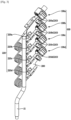
bracket 200 supports the plurality ofexpansion valve units FIG. 3 . - According to an embodiment of the invention, the
bracket 200 may support four or lessexpansion valve units bracket 200 may include five or more coupling hooks 203 andcoupling holes 205, which are described later, for supporting five or more expansion valve units. However, hereinafter thebracket 200 configured to support four or lessexpansion valve units - Four or less
expansion valve units bracket 200 configured to support fourexpansion valve units expansion valve units bracket 200. - That is, the
outdoor unit 10 may include various numbers ofexpansion valve units 100 according to the number of theindoor units 20 connected to theoutdoor unit 10 but includes at least oneexpansion valve unit 100, and one expansion valve unit to four expansion valve units may be supported by asingle bracket 200. Theoutdoor unit 10 includes a plurality offirst coupling members expansion valve units bracket 200, respectively. - The
outdoor unit 10 includes a plurality ofsecond coupling members expansion valve units bracket 200, respectively. - Two fixation points fixed to the
bracket 200 by thefirst coupling member 210 and thesecond coupling member 220 are formed on theexpansion valve unit 100. Accordingly, theexpansion valve unit 100 is stably fixed to thebracket 200. - The number of the
first coupling members second coupling members expansion valve units bracket 200. - Hereinafter a structure in which the
expansion valve unit 100 is coupled to thebracket 200 will be described in detail. -
FIG. 5 is an exploded perspective view illustrating a first coupling member, a second coupling member, and the bracket in the air conditioner according to an embodiment of the invention, -
FIG. 6 is a view illustrating one surface of the bracket in a state in which the expansion valve unit is fixed to the bracket, in the air conditioner according to an embodiment of the invention, andFIG. 7 is a view illustrating the other surface of the bracket in a state in which the expansion valve unit is fixed to the bracket, in the air conditioner according to an embodiment of the invention. - The
expansion valve units expansion valve unit 100a among theexpansion valve units expansion valve unit 100. Thefirst coupling members first coupling member 210a corresponding to one of the plurality offirst coupling members first coupling member 210. - Further, the
second coupling members second coupling member 220a corresponding to one of the plurality ofsecond coupling members second coupling member 220. - Four
coupling hooks coupling holes bracket 200 in accordance with the number of theexpansion valve units - The four
coupling hooks coupling holes coupling hook 203a among the plurality ofcoupling hooks coupling hook 203 and onecoupling hole 205a among the plurality ofcoupling holes coupling hole 205. - Further, one guide hole 206a among the plurality of guide holes 206a, 206b, 206c, and 206d to be described later will be described as an example of the guide hole 206.
- As illustrated in
FIGS. 5 to 7 , thebracket 200. is configured to fix theexpansion valve 110 and thefirst connection portion 120. - The
expansion valve 110 is coupled by thefirst coupling member 210, and thefirst connection portion 120 may be coupled by thesecond coupling member 220. - Particularly, the
second coupling member 220 fixes thefirst connection tube 140 among thefirst connection portion 120 to thebracket 200. - The
first coupling member 210 surrounds at least a portion of theexpansion valve 110 and then fixed to thebracket 200 so as to allow theexpansion valve 110 to be stably supported by thebracket 200. - Particularly, the
first coupling member 210 may surround alower portion 111a of thebody portion 111 of theexpansion valve 110 to stably support thebody portion 111 having a relatively heavy weight. However, the disclosure is not limited thereto, and thefirst coupling member 210 may surround other portions of thebody portion 111. - Accordingly, because the
body portion 111 is fixed to thebracket 200, it is possible to allow the external force, which is generated by the weight of thebody portion 111, to be minimally transmitted to thefirst tube 112 extending from thebody portion 111 and theother end 132 of thecapillary tube 130, which is connected to thefirst tube 112. - The
first coupling member 210 may include afirst cutout portion 213, and afirst support 211 configured to surround and support thebody portion 111 inserted through thefirst cutout portion 213. - The
first support 211 may be formed in a ring shape with one side cut off. Thefirst cutout portion 213 may be arranged at one side of thefirst support 211. - A first inserting
portion 212, which is a space into which thebody portion 111 may be inserted, may be provided inside thefirst support 211. - The
lower portion 111a of thebody portion 111 may be inserted into thefirst insertion portion 212 through thefirst cutout portion 213, and an inner circumferential surface of thefirst support 211 may surround an outer circumferential surface of thelower portion 111a of thebody portion 111, thereby supporting thebody portion 111. - The
first coupling member 210 may include a rubber material. Accordingly, a cut range of thefirst cutout portion 213 may be increased or decreased by an external force, and thus thebody portion 111 may be easily inserted into thefirst insertion portion 212. - The
first coupling member 210 includes afirst coupling portion 214 extending from thefirst cutout portion 213 to the opposite side of thefirst support 211 and coupled to thebracket 200. - The
first coupling portion 214 may be provided in a pair of protrusion shapes extending from thefirst cutout portion 213. Thefirst coupling portion 214 may be hooked to aninner space 204 of thecoupling hook 203 formed in thebracket 200. - As mentioned above, the
first coupling member 210 includes the rubber material and the elasticity may be maintained so that the pair of protrusion shapes of thefirst coupling portion 214 is directed to the outside. When the pair of coupling protrusions is arranged in theinner space 204 of thecoupling hook 203, the pair of coupling protrusions may be hooked to thecoupling hook 203 by the elasticity. - Further, the
first coupling member 210 includes asupport protrusion 215 arranged on thefirst coupling portion 214 to prevent thefirst coupling member 210 from being separated from thecoupling hook 203. - Because a
coupling space 216 between thesupport protrusion 215 and thefirst support 211 is arranged in theinner space 204 of thecoupling hook 203, it is possible to maintain a state in which thefirst coupling portion 214 is stably coupled to thecoupling hook 203. - Because the
first coupling member 210 includes the rubber material as mentioned above, it is possible to generate the anti-vibration effect against the vibration generated in theoutdoor unit 10. Accordingly, thefirst coupling member 210 may stably couple theexpansion valve unit 100 to thebracket 200, and further secure the rigidity of theexpansion valve unit 100. - The
second coupling member 220 includes asecond support 221 configured to surround and support thefirst connection tube 140, asecond insertion portion 222 provided inside thesecond support 221 and to which thefirst connection tube 140 is inserted, and asecond cutout portion 223 formed cutout to allow thefirst connection tube 140 to be inserted to thesecond insertion portion 222. - As for the
first connection tube 140, thesecond support 221 surrounds the vicinity of the oneend 141 of thefirst connection tube 140 coupled to the oneend 131 of thecapillary tube 130. - Alternatively, the
second support 221 may surround the oneend 141 of thefirst connection tube 140 although not shown in the drawings That is, in thefirst connection portion 120, the oneend 131 of thecapillary tube 130, the oneend 141 of thefirst connection tube 140, and the vicinity of the oneend 141 of thefirst connection tube 140, which are a portion vulnerable to damage due to external force, are supported by thesecond support 221, thereby increasing the rigidity of thefirst connection portion 120. - In addition, as described above, the rigidity of the other end of the
capillary tube 130, thefirst tube 112 or a portion arranged in theauxiliary tube 112a, which are another portion vulnerable to damage due to external force, in thefirst connection portion 120 may be increased because thefirst coupling member 210 stably supports thebody portion 111. - The
second coupling member 220 includes asecond coupling portion 224 extending from thesecond cutout portion 223 to the opposite side of thesecond support 221 and coupled to thebracket 200. - The
second coupling portion 224 may be screwed to thecoupling hole 205 formed in thebracket 200. Thesecond coupling portion 224 includes a pair of plates extending from thesecond cutout portion 223, and each plate may include a throughhole 224 to which the screw S is passed through and which is coupled to thecoupling hole 205. - The
bracket 200 may include the guide hole 206 arranged adjacent to thecoupling hole 205 and configured to guide a position at which thesecond coupling member 220 is coupled to thebracket 200. - As will be described later, the
expansion valve unit 100 may be arranged to be inclined with respect to oneend 200a or theother end 200b of thebracket 200. The guide hole 206 may guide the position of thesecond coupling member 220 to allow thesecond coupling member 220 to be coupled to thebracket 200 at an angle in consideration of an installation angle of theexpansion valve unit 100. - The
second coupling member 220 may include a guide protrusion 226 inserted into the guide hole 206. Particularly, the guide protrusion 226 may protrude from thesecond coupling portion 224, which is in contact with onesurface 201 of thebracket 200, to a direction coupled to thebracket 200. - Before the
second coupling member 220 is coupled to thebracket 200, the guide protrusion 226 may be inserted into theguide hole 205 of thebracket 200 so as to select the position of thesecond coupling member 220. Thereafter, thesecond coupling member 220 may be arranged at a position where thecoupling hole 205 and the throughhole 224 overlap each other, and thesecond coupling member 220 and thebracket 200 may be coupled to each other through the screw member S. - As mentioned above, the
first coupling member 210 and thesecond coupling member 220 fix theexpansion valve unit 100 to thebracket 200. Accordingly, two fixation points in theexpansion valve unit 100 are fixed to thebracket 200 by thefirst coupling member 210 and thesecond coupling member 220. - Particularly, the
first coupling member 210 and thesecond coupling member 220 increase the rigidity of theexpansion valve unit 100 by fixing the low rigidity portion of theexpansion valve unit 100 to thebracket 200. - The
first connection tube 140 is fixed to the onesurface 201 of thebracket 200 by thesecond coupling member 220, and theexpansion valve 110 is fixed to the other surface 202 of thebracket 200, which is opposite do the onesurface 201 of thebracket 200, by thefirst coupling member 210. - That is, the
first coupling member 210 and thesecond coupling member 220 respectively fix theexpansion valve 110 and the first connectingpipe 140 to thebracket 200 in the opposite direction. - When the
first coupling member 210 and thesecond coupling member 220 are simultaneously coupled on the same surface of thebracket 200, a part of theexpansion valve unit 100 may be deformed by the shape of thecapillary tube 130. However, according the invention, because theexpansion valve 110 is coupled to the other surface 202 of thebracket 200 and thefirst connection tube 140 is coupled to the onesurface 201 of thebracket 200, theexpansion valve unit 100 is easily coupled to thebracket 200 without deformation. - Alternatively, when the
capillary tube 130 is arranged on thesecond connection portion 150 as described above, theexpansion valve 110 is arranged on the onesurface 201 of thebracket 200 and thesecond connection portion 150 is arranged on the other surface 202 of thebracket 200 by thesecond coupling member 220 although not shown in the drawings. - The
coupling hook 203 may extend outwardly from the oneend 200a of thebracket 200. Thecoupling hole 205 may be arranged at a portion adjacent to theother end 200b arranged in the opposite direction of the oneend 200a of thebracket 200. - That is, on the same surface of the
bracket 200, thecoupling hook 203 and thecoupling hole 205 may be arranged adjacent toopposite ends - Therefore, the
expansion valve unit 100 is coupled to thebracket 200 by being constrained in a region adjacent to the oneend 200a of thebracket 200 and a region adjacent to theother end 200b. - The plurality of
coupling hooks coupling holes end 200a or theother end 200b of thebracket 200 extends. - In a
single bracket 200, the plurality ofexpansion valve units bracket 200. - Accordingly, the pipe laying in the machine room may have a simple structure and thus the inner space of the machine room may be efficiently used. Therefore, it is possible to minimize collision between components and it is possible to prevent that each
expansion valve unit - The
coupling hook 203 may extend outwardly at a predetermined angle θwith respect to a direction perpendicular to the extending direction of the oneend 200a or theother end 200b of thebracket 200. - That is, the
coupling hook 203 may extend in a direction inclined with respect to the oneend 200a of thebracket 200. Accordingly, theexpansion valve unit 100 may be coupled at an angle with respect to the oneend 200a or theother end 200b of thebracket 200. - A length L from the
other end 200b of thebracket 200 to one end of thebody portion 111 of theexpansion valve unit 100 when theexpansion valve unit 100 is coupled to thebracket 200 in a direction inclined with respect to the oneend 200a of thebracket 200 may be less than a length from theother end 200b of thebracket 200 to one end of thebody portion 111 of theexpansion valve unit 100 when theexpansion valve unit 100 is coupled to thebracket 200 in a direction perpendicular to the oneend 200a of thebracket 200. - Therefore, the length from the outermost side of the
expansion valve unit 100 coupled to thedischarge pipe 15 to thedischarge pipe 15 may be formed relatively short, and thus it is possible to efficiently use the inner space of the machine room. - When it is assumed that a direction, in which the one
end 131 of thecapillary tube 130 is formed (or a direction in which one side of thecapillary tube 130 including the oneend 131 extends), is e1, and it is assumed that a direction, in which theother end 132 of thecapillary tube 130 is formed (or a direction in which the other side of thecapillary tube 130 including the other end extends), is e2, thefirst coupling member 210 may constrain theexpansion valve 110 in the direction e2 and thesecond coupling member 220 may constrain thefirst connection tube 140 in the direction e1. - Accordingly, even when the external force is applied to a direction in which the one
end 131 and theother end 132 of thecapillary tube 130 are away from each other, or a direction in which the oneend 131 and theother end 132 of thecapillary tube 130 are close to each other, it is possible to prevent that thecapillary tube 130 is deformed in the direction in which the oneend 131 and theother end 132 are away from each other or close to each other. - That is, the
bracket 200 supports theexpansion valve 110 and thefirst connection tube 140 to maintain a separation distance d in a direction perpendicular to the expanding directions e1 and e2 of the oneend 131 and theother end 132 of thecapillary tube 130. - Because the separation distance d between the one
end 131 and theother end 132 of thecapillary tube 130 is maintained by thefirst coupling member 210 and thesecond coupling member 220, it is possible to prevent thecapillary tube 130 from being deformed due to the external force. - Hereinafter a
bracket 300 configured to stably support theexpansion valve unit 100 according to another embodiment of the invention will be described. A configuration will be described later except thebracket 300 may be the same as the configuration of theoutdoor unit 10 of the air conditioner according to an embodiment and thus a description thereof will be omitted.FIG. 8 is a schematic diagram of an air conditioner according to another embodiment of the invention, andFIG. 9 is a view illustrating one surface of a bracket in a state in which an expansion valve unit is fixed to the bracket, in the air conditioner according to another embodiment of the invention. - As illustrated in
FIG. 8 , a singleindoor unit 20 may be connected to a singleoutdoor unit 10. Accordingly, a singleexpansion valve unit 100 may be arranged in theoutdoor unit 10. When a singleexpansion valve unit 100 is arranged in the machine room, theexpansion valve unit 100 may be coupled to any one of the plurality ofcoupling hooks coupling holes bracket 200. - However, unlike this, the
bracket 300 according to another embodiment of the invention includes onecoupling hook 303 and one coupling hole (not shown). - Accordingly, a length of one
end 300a or theother end 300b of thebracket 300 may be shortened, and thus thebracket 300 may be smaller than thebracket 200 according to an embodiment of the disclosure. - Because the size of the
bracket 300 is reduced, the space inside the machine room of theoutdoor unit 10 may be effectively used, and thus theexpansion valve unit 100 may be prevented from being damaged due to contact with other components. - In addition, although not shown in the drawings, the
bracket 300 may be implemented by a bracket including two coupling hooks and two coupling holes, or three coupling hooks and three coupling holes. - That is, unlike the other embodiments of the invention, the bracket may include various numbers of coupling hooks and coupling holes.
Claims (12)
- An outdoor unit (10) of an air conditioner connectable to an indoor unit (20, 20a, 20b), the outdoor unit (10) comprising:a compressor (13);a heat exchanger (11) configured to exchange heat between air introduced from outside and refrigerant compressed by the compressor (13);an expansion valve unit (100) configured to decompress the refrigerant discharged from the heat exchanger (11), the expansion valve unit (100) comprising an expansion valve (110), a first connection portion (120) configured to connect the expansion valve (110) to the heat exchanger (11) and a second connection portion (150) configured to connect the expansion valve (110) to a refrigerant pipe (30), the refrigerant pipe (30) configured to deliver the refrigerant, which is decompressed and expanded by the expansion valve unit (100), to the indoor unit (20, 20a, 20b) when the indoor unit (20, 20a, 20b) is connected to the outdoor unit (10); anda bracket (200, 300) configured to support the expansion valve unit (100) by fixing the expansion valve (110) and one of the first connection portion (120) or the second connection portion (150) to the bracket (200, 300),characterized in thatthe one of the first connection portion (120) or the second connection portion (150) comprises a capillary tube (130) connected to the expansion valve (110) and a connection tube (140) configured to connect the capillary tube (130) to the heat exchanger (11) or the refrigerant pipe (30), and the connection tube (140) is fixed to the bracket (200, 300),and in that the expansion valve (110) is fixed to one surface (202) of the bracket (200, 300) and the connection tube (140) is fixed to the other surface (201) of the bracket (200, 300).
- The outdoor unit (10) of the air conditioner of claim 1, wherein
the expansion valve (110) is fixed to one side of the bracket (200, 300),
wherein the one of the first connection portion (120) or the second connection portion (150) is fixed to the other side of the bracket (200, 300). - The outdoor unit (10) of the air conditioner of claim 1, wherein
the capillary tube (130) comprises one end (131) thereof connected to the connection tube and the other end (132, 142, 200b, 300b) thereof connected to the expansion valve (110),
wherein the bracket (200, 300) fixes the expansion valve (110) and the connection tube to maintain a separation distance in a direction perpendicular to an extending direction of the one end (131, 141, 200a) and the other end (132, 142, 200b, 300b) of the capillary tube (130). - The outdoor unit (10) of the air conditioner of claim 1, further comprising:
a first coupling member (210, 210a, 210b, 210c, 210d) configured to surround at least a portion (212) of the expansion valve (110) and coupled to the bracket (200, 300) so as to allow the expansion valve (110) to be coupled to the bracket (200, 300). - The outdoor unit (10) of the air conditioner of claim 4, wherein
the first coupling member (210, 210a, 210b, 210c, 210d) comprises a rubber material. - The outdoor unit (10) of the air conditioner of claim 4, wherein
the first coupling member (210, 210a, 210b, 210c, 210d) comprises a first cutout portion (213), a first support (211) configured to support at least one portion (212) of the expansion valve (110) after a lower end of the expansion valve (110) is inserted through the first cutout portion, and a first coupling portion extending from the first cutout portion and coupled to the bracket (200, 300). - The outdoor unit (10) of the air conditioner of claim 6, wherein
the first coupling portion (214) comprises a support protrusion (215) configured to allow the first coupling portion (214) to be supported by the bracket (200, 300) without being separated from the bracket (200, 300) after the first coupling portion (214) is inserted into the bracket (200, 300). - The outdoor unit (10) of the air conditioner of claim 7, wherein
the bracket (200 300) comprises a coupling hook (203a, 203b, 203c, 203d) comprising an insertion portion (212) to which the first coupling portion (214) is inserted - The outdoor unit (10) of the air conditioner of claim 8, wherein
the coupling hook (203a, 203b, 203c, 203d) is arranged at one side end of the bracket (200, 300). - The outdoor unit (10) of the air conditioner of claim 1, further comprising:
a second coupling member (220, 220a, 220b, 220c, 220d) configured to surround one of the first connection portion (120) or the second connection portion (150) and coupled to the bracket (200, 300) so as to allow the one of the first connection portion (120) or the second connection portion (150) to be coupled to the bracket (200, 300). - The outdoor unit (10) of the air conditioner of claim 10, wherein
the second coupling member (220, 220a, 220b, 220c, 220d) comprises a second support (221) configured to surround the one of the first connection portion (120) or the second connection portion (150) and support the one of the first connection portion (120) or the second connection portion (150), and a second coupling portion (212) coupled to the bracket (200, 300). - The outdoor unit (10) of the air conditioner of claim 11, wherein
the second coupling portion (212) is screwed to the bracket (200, 300),
wherein the bracket (200, 300) further comprises a coupling hole (205a, 205b, 205c, 205d) to which the second coupling portion (212) is screwed.
Applications Claiming Priority (2)
| Application Number | Priority Date | Filing Date | Title |
|---|---|---|---|
| KR1020190012968A KR102596984B1 (en) | 2019-01-31 | 2019-01-31 | Outdoor unit of airconditioner |
| PCT/KR2020/001331 WO2020159215A1 (en) | 2019-01-31 | 2020-01-29 | Outdoor unit of air conditioner |
Publications (3)
| Publication Number | Publication Date |
|---|---|
| EP3903043A1 EP3903043A1 (en) | 2021-11-03 |
| EP3903043A4 EP3903043A4 (en) | 2022-03-02 |
| EP3903043B1 true EP3903043B1 (en) | 2023-10-25 |
Family
ID=71836279
Family Applications (1)
| Application Number | Title | Priority Date | Filing Date |
|---|---|---|---|
| EP20748510.3A Active EP3903043B1 (en) | 2019-01-31 | 2020-01-29 | Outdoor unit of air conditioner |
Country Status (4)
| Country | Link |
|---|---|
| US (1) | US11378288B2 (en) |
| EP (1) | EP3903043B1 (en) |
| KR (1) | KR102596984B1 (en) |
| WO (1) | WO2020159215A1 (en) |
Families Citing this family (3)
| Publication number | Priority date | Publication date | Assignee | Title |
|---|---|---|---|---|
| JP7308434B2 (en) * | 2018-07-31 | 2023-07-14 | パナソニックIpマネジメント株式会社 | Outdoor unit |
| CN116034235B (en) * | 2020-09-14 | 2025-05-27 | 日本开利株式会社 | Outdoor unit of air conditioner |
| WO2026018321A1 (en) * | 2024-07-17 | 2026-01-22 | 三菱電機株式会社 | Outdoor unit and refrigeration cycle device |
Family Cites Families (18)
| Publication number | Priority date | Publication date | Assignee | Title |
|---|---|---|---|---|
| SE501059C2 (en) * | 1992-03-27 | 1994-10-31 | Lars Lilja | Fasteners for attaching e.g. net or rope to a carrier |
| JPH09196515A (en) * | 1996-01-22 | 1997-07-31 | Izumi Giken:Kk | Piping unit of heat pump type air conditioner |
| KR19980012019U (en) * | 1996-08-23 | 1998-05-25 | 추호석 | Hollow clamp |
| JPH1096540A (en) * | 1996-09-20 | 1998-04-14 | Fujitsu General Ltd | Outdoor unit of air conditioner |
| JP3894142B2 (en) * | 2003-03-20 | 2007-03-14 | 松下電器産業株式会社 | Channel branch device |
| KR20070081239A (en) | 2006-02-10 | 2007-08-16 | 한라공조주식회사 | Clip structure for fixing refrigerant pipe |
| JP4814813B2 (en) * | 2007-02-21 | 2011-11-16 | ヤンマー株式会社 | Air conditioner |
| KR20090022119A (en) * | 2007-08-29 | 2009-03-04 | 엘지전자 주식회사 | Detachable multi-air conditioner with service valve assembly |
| CN102192624B (en) * | 2010-03-11 | 2014-11-26 | Lg电子株式会社 | Outdoor unit, distribution unit and air conditioning device including them |
| KR101727034B1 (en) * | 2010-03-11 | 2017-04-14 | 엘지전자 주식회사 | Air conditioner |
| JP5447231B2 (en) * | 2010-06-30 | 2014-03-19 | 株式会社富士通ゼネラル | Air conditioner refrigerant branching unit |
| KR102108523B1 (en) * | 2013-04-05 | 2020-05-08 | 삼성전자주식회사 | Air cleaner |
| KR20140139318A (en) | 2013-05-27 | 2014-12-05 | 한라비스테온공조 주식회사 | Air conditioning system for automotive vehicles |
| CN203837207U (en) * | 2014-03-25 | 2014-09-17 | 广东美的暖通设备有限公司 | Air conditioner and valve mounting plate components thereof |
| EP3048390A1 (en) * | 2015-01-26 | 2016-07-27 | Danfoss A/S | Bulb for a thermostatic expansion valve, set comprising a bulb and at least a part of a thermostatic expansion valve connected to a capillary and method for connecting a bulb and a capillary of a thermostatic expansion valve |
| CN205090680U (en) * | 2015-10-19 | 2016-03-16 | 格力电器(武汉)有限公司 | Fixing device for air conditioner, outdoor unit and throttling assembly thereof |
| KR102147693B1 (en) * | 2016-10-28 | 2020-08-25 | 미쓰비시덴키 가부시키가이샤 | Air conditioner |
| KR20180104560A (en) | 2017-03-13 | 2018-09-21 | 한온시스템 주식회사 | Pipe insulator for vehicle |
-
2019
- 2019-01-31 KR KR1020190012968A patent/KR102596984B1/en active Active
-
2020
- 2020-01-29 EP EP20748510.3A patent/EP3903043B1/en active Active
- 2020-01-29 WO PCT/KR2020/001331 patent/WO2020159215A1/en not_active Ceased
- 2020-01-31 US US16/778,613 patent/US11378288B2/en active Active
Also Published As
| Publication number | Publication date |
|---|---|
| EP3903043A1 (en) | 2021-11-03 |
| US20200248912A1 (en) | 2020-08-06 |
| US11378288B2 (en) | 2022-07-05 |
| KR20200095185A (en) | 2020-08-10 |
| EP3903043A4 (en) | 2022-03-02 |
| WO2020159215A1 (en) | 2020-08-06 |
| KR102596984B1 (en) | 2023-11-02 |
Similar Documents
| Publication | Publication Date | Title |
|---|---|---|
| EP2365254A2 (en) | Air conditioner | |
| AU2021277705B2 (en) | Air-conditioning apparatus, and refrigeration cycle apparatus | |
| US11378288B2 (en) | Outdoor unit of airconditioner | |
| EP2037187A2 (en) | Outdoor unit of air conditioner | |
| EP2365255A2 (en) | Air conditioning device | |
| EP3712517B1 (en) | Outdoor unit of air conditioner | |
| JP2007120900A (en) | Shut-off valve support member and outdoor unit of air conditioner having the same | |
| EP2180265A2 (en) | Outdoor unit of air conditioner | |
| US10436459B2 (en) | Air guide for air conditioner | |
| JP6732110B2 (en) | Outdoor unit, air conditioner, and method of manufacturing outdoor unit | |
| KR20030038503A (en) | Air conditioner | |
| US20080314068A1 (en) | Outdoor unit of air conditioner | |
| CN114938658B (en) | Outdoor unit of refrigeration cycle device | |
| KR100441101B1 (en) | The lead mounting of an air-conditioner | |
| EP3385627B1 (en) | Outdoor unit | |
| WO2017138139A1 (en) | Electric equipment unit and air-conditioning device | |
| KR20100084402A (en) | Air conditioner | |
| EP1735570A2 (en) | Pipe support for compressor subassembly | |
| JP7412602B2 (en) | Air conditioner indoor unit | |
| KR20110102615A (en) | Air conditioner | |
| KR20050117664A (en) | Outdoor unit of separable type air conditioner | |
| CN219367924U (en) | Fixing piece and air conditioner | |
| WO2020183607A1 (en) | Indoor unit | |
| KR20070077409A (en) | Outdoor unit of air conditioner | |
| KR100416704B1 (en) | A combined direct exhaust type and duct type a package air conditioner inner part |
Legal Events
| Date | Code | Title | Description |
|---|---|---|---|
| STAA | Information on the status of an ep patent application or granted ep patent |
Free format text: STATUS: THE INTERNATIONAL PUBLICATION HAS BEEN MADE |
|
| PUAI | Public reference made under article 153(3) epc to a published international application that has entered the european phase |
Free format text: ORIGINAL CODE: 0009012 |
|
| STAA | Information on the status of an ep patent application or granted ep patent |
Free format text: STATUS: REQUEST FOR EXAMINATION WAS MADE |
|
| 17P | Request for examination filed |
Effective date: 20210727 |
|
| AK | Designated contracting states |
Kind code of ref document: A1 Designated state(s): AL AT BE BG CH CY CZ DE DK EE ES FI FR GB GR HR HU IE IS IT LI LT LU LV MC MK MT NL NO PL PT RO RS SE SI SK SM TR |
|
| A4 | Supplementary search report drawn up and despatched |
Effective date: 20220128 |
|
| RIC1 | Information provided on ipc code assigned before grant |
Ipc: F24F 1/46 20110101ALI20220124BHEP Ipc: F25B 41/31 20210101ALI20220124BHEP Ipc: F24F 11/84 20180101ALI20220124BHEP Ipc: F24F 11/46 20180101ALI20220124BHEP Ipc: F16B 2/14 20060101ALI20220124BHEP Ipc: F16B 2/06 20060101ALI20220124BHEP Ipc: F24F 1/40 20110101ALI20220124BHEP Ipc: F24F 1/30 20110101ALI20220124BHEP Ipc: F24F 1/34 20110101AFI20220124BHEP |
|
| DAV | Request for validation of the european patent (deleted) | ||
| DAX | Request for extension of the european patent (deleted) | ||
| GRAP | Despatch of communication of intention to grant a patent |
Free format text: ORIGINAL CODE: EPIDOSNIGR1 |
|
| STAA | Information on the status of an ep patent application or granted ep patent |
Free format text: STATUS: GRANT OF PATENT IS INTENDED |
|
| RIC1 | Information provided on ipc code assigned before grant |
Ipc: F24F 1/46 20110101ALI20230515BHEP Ipc: F25B 41/31 20210101ALI20230515BHEP Ipc: F24F 11/84 20180101ALI20230515BHEP Ipc: F24F 11/46 20180101ALI20230515BHEP Ipc: F16B 2/14 20060101ALI20230515BHEP Ipc: F16B 2/06 20060101ALI20230515BHEP Ipc: F24F 1/40 20110101ALI20230515BHEP Ipc: F24F 1/30 20110101ALI20230515BHEP Ipc: F24F 1/34 20110101AFI20230515BHEP |
|
| INTG | Intention to grant announced |
Effective date: 20230606 |
|
| GRAS | Grant fee paid |
Free format text: ORIGINAL CODE: EPIDOSNIGR3 |
|
| GRAA | (expected) grant |
Free format text: ORIGINAL CODE: 0009210 |
|
| STAA | Information on the status of an ep patent application or granted ep patent |
Free format text: STATUS: THE PATENT HAS BEEN GRANTED |
|
| AK | Designated contracting states |
Kind code of ref document: B1 Designated state(s): AL AT BE BG CH CY CZ DE DK EE ES FI FR GB GR HR HU IE IS IT LI LT LU LV MC MK MT NL NO PL PT RO RS SE SI SK SM TR |
|
| REG | Reference to a national code |
Ref country code: GB Ref legal event code: FG4D |
|
| REG | Reference to a national code |
Ref country code: CH Ref legal event code: EP |
|
| REG | Reference to a national code |
Ref country code: DE Ref legal event code: R096 Ref document number: 602020019857 Country of ref document: DE |
|
| REG | Reference to a national code |
Ref country code: IE Ref legal event code: FG4D |
|
| REG | Reference to a national code |
Ref country code: LT Ref legal event code: MG9D |
|
| REG | Reference to a national code |
Ref country code: NL Ref legal event code: MP Effective date: 20231025 |
|
| REG | Reference to a national code |
Ref country code: AT Ref legal event code: MK05 Ref document number: 1625014 Country of ref document: AT Kind code of ref document: T Effective date: 20231025 |
|
| PG25 | Lapsed in a contracting state [announced via postgrant information from national office to epo] |
Ref country code: NL Free format text: LAPSE BECAUSE OF FAILURE TO SUBMIT A TRANSLATION OF THE DESCRIPTION OR TO PAY THE FEE WITHIN THE PRESCRIBED TIME-LIMIT Effective date: 20231025 |
|
| PG25 | Lapsed in a contracting state [announced via postgrant information from national office to epo] |
Ref country code: GR Free format text: LAPSE BECAUSE OF FAILURE TO SUBMIT A TRANSLATION OF THE DESCRIPTION OR TO PAY THE FEE WITHIN THE PRESCRIBED TIME-LIMIT Effective date: 20240126 |
|
| PG25 | Lapsed in a contracting state [announced via postgrant information from national office to epo] |
Ref country code: IS Free format text: LAPSE BECAUSE OF FAILURE TO SUBMIT A TRANSLATION OF THE DESCRIPTION OR TO PAY THE FEE WITHIN THE PRESCRIBED TIME-LIMIT Effective date: 20240225 |
|
| PG25 | Lapsed in a contracting state [announced via postgrant information from national office to epo] |
Ref country code: LT Free format text: LAPSE BECAUSE OF FAILURE TO SUBMIT A TRANSLATION OF THE DESCRIPTION OR TO PAY THE FEE WITHIN THE PRESCRIBED TIME-LIMIT Effective date: 20231025 |
|
| PG25 | Lapsed in a contracting state [announced via postgrant information from national office to epo] |
Ref country code: AT Free format text: LAPSE BECAUSE OF FAILURE TO SUBMIT A TRANSLATION OF THE DESCRIPTION OR TO PAY THE FEE WITHIN THE PRESCRIBED TIME-LIMIT Effective date: 20231025 |
|
| PG25 | Lapsed in a contracting state [announced via postgrant information from national office to epo] |
Ref country code: ES Free format text: LAPSE BECAUSE OF FAILURE TO SUBMIT A TRANSLATION OF THE DESCRIPTION OR TO PAY THE FEE WITHIN THE PRESCRIBED TIME-LIMIT Effective date: 20231025 |
|
| PG25 | Lapsed in a contracting state [announced via postgrant information from national office to epo] |
Ref country code: LT Free format text: LAPSE BECAUSE OF FAILURE TO SUBMIT A TRANSLATION OF THE DESCRIPTION OR TO PAY THE FEE WITHIN THE PRESCRIBED TIME-LIMIT Effective date: 20231025 Ref country code: IS Free format text: LAPSE BECAUSE OF FAILURE TO SUBMIT A TRANSLATION OF THE DESCRIPTION OR TO PAY THE FEE WITHIN THE PRESCRIBED TIME-LIMIT Effective date: 20240225 Ref country code: GR Free format text: LAPSE BECAUSE OF FAILURE TO SUBMIT A TRANSLATION OF THE DESCRIPTION OR TO PAY THE FEE WITHIN THE PRESCRIBED TIME-LIMIT Effective date: 20240126 Ref country code: ES Free format text: LAPSE BECAUSE OF FAILURE TO SUBMIT A TRANSLATION OF THE DESCRIPTION OR TO PAY THE FEE WITHIN THE PRESCRIBED TIME-LIMIT Effective date: 20231025 Ref country code: BG Free format text: LAPSE BECAUSE OF FAILURE TO SUBMIT A TRANSLATION OF THE DESCRIPTION OR TO PAY THE FEE WITHIN THE PRESCRIBED TIME-LIMIT Effective date: 20240125 Ref country code: AT Free format text: LAPSE BECAUSE OF FAILURE TO SUBMIT A TRANSLATION OF THE DESCRIPTION OR TO PAY THE FEE WITHIN THE PRESCRIBED TIME-LIMIT Effective date: 20231025 Ref country code: PT Free format text: LAPSE BECAUSE OF FAILURE TO SUBMIT A TRANSLATION OF THE DESCRIPTION OR TO PAY THE FEE WITHIN THE PRESCRIBED TIME-LIMIT Effective date: 20240226 |
|
| PG25 | Lapsed in a contracting state [announced via postgrant information from national office to epo] |
Ref country code: SE Free format text: LAPSE BECAUSE OF FAILURE TO SUBMIT A TRANSLATION OF THE DESCRIPTION OR TO PAY THE FEE WITHIN THE PRESCRIBED TIME-LIMIT Effective date: 20231025 Ref country code: RS Free format text: LAPSE BECAUSE OF FAILURE TO SUBMIT A TRANSLATION OF THE DESCRIPTION OR TO PAY THE FEE WITHIN THE PRESCRIBED TIME-LIMIT Effective date: 20231025 Ref country code: PL Free format text: LAPSE BECAUSE OF FAILURE TO SUBMIT A TRANSLATION OF THE DESCRIPTION OR TO PAY THE FEE WITHIN THE PRESCRIBED TIME-LIMIT Effective date: 20231025 Ref country code: NO Free format text: LAPSE BECAUSE OF FAILURE TO SUBMIT A TRANSLATION OF THE DESCRIPTION OR TO PAY THE FEE WITHIN THE PRESCRIBED TIME-LIMIT Effective date: 20240125 Ref country code: LV Free format text: LAPSE BECAUSE OF FAILURE TO SUBMIT A TRANSLATION OF THE DESCRIPTION OR TO PAY THE FEE WITHIN THE PRESCRIBED TIME-LIMIT Effective date: 20231025 Ref country code: HR Free format text: LAPSE BECAUSE OF FAILURE TO SUBMIT A TRANSLATION OF THE DESCRIPTION OR TO PAY THE FEE WITHIN THE PRESCRIBED TIME-LIMIT Effective date: 20231025 |
|
| PG25 | Lapsed in a contracting state [announced via postgrant information from national office to epo] |
Ref country code: DK Free format text: LAPSE BECAUSE OF FAILURE TO SUBMIT A TRANSLATION OF THE DESCRIPTION OR TO PAY THE FEE WITHIN THE PRESCRIBED TIME-LIMIT Effective date: 20231025 |
|
| PG25 | Lapsed in a contracting state [announced via postgrant information from national office to epo] |
Ref country code: CZ Free format text: LAPSE BECAUSE OF FAILURE TO SUBMIT A TRANSLATION OF THE DESCRIPTION OR TO PAY THE FEE WITHIN THE PRESCRIBED TIME-LIMIT Effective date: 20231025 |
|
| REG | Reference to a national code |
Ref country code: DE Ref legal event code: R097 Ref document number: 602020019857 Country of ref document: DE |
|
| PG25 | Lapsed in a contracting state [announced via postgrant information from national office to epo] |
Ref country code: SK Free format text: LAPSE BECAUSE OF FAILURE TO SUBMIT A TRANSLATION OF THE DESCRIPTION OR TO PAY THE FEE WITHIN THE PRESCRIBED TIME-LIMIT Effective date: 20231025 |
|
| PG25 | Lapsed in a contracting state [announced via postgrant information from national office to epo] |
Ref country code: SM Free format text: LAPSE BECAUSE OF FAILURE TO SUBMIT A TRANSLATION OF THE DESCRIPTION OR TO PAY THE FEE WITHIN THE PRESCRIBED TIME-LIMIT Effective date: 20231025 Ref country code: SK Free format text: LAPSE BECAUSE OF FAILURE TO SUBMIT A TRANSLATION OF THE DESCRIPTION OR TO PAY THE FEE WITHIN THE PRESCRIBED TIME-LIMIT Effective date: 20231025 Ref country code: RO Free format text: LAPSE BECAUSE OF FAILURE TO SUBMIT A TRANSLATION OF THE DESCRIPTION OR TO PAY THE FEE WITHIN THE PRESCRIBED TIME-LIMIT Effective date: 20231025 Ref country code: IT Free format text: LAPSE BECAUSE OF FAILURE TO SUBMIT A TRANSLATION OF THE DESCRIPTION OR TO PAY THE FEE WITHIN THE PRESCRIBED TIME-LIMIT Effective date: 20231025 Ref country code: EE Free format text: LAPSE BECAUSE OF FAILURE TO SUBMIT A TRANSLATION OF THE DESCRIPTION OR TO PAY THE FEE WITHIN THE PRESCRIBED TIME-LIMIT Effective date: 20231025 Ref country code: DK Free format text: LAPSE BECAUSE OF FAILURE TO SUBMIT A TRANSLATION OF THE DESCRIPTION OR TO PAY THE FEE WITHIN THE PRESCRIBED TIME-LIMIT Effective date: 20231025 Ref country code: CZ Free format text: LAPSE BECAUSE OF FAILURE TO SUBMIT A TRANSLATION OF THE DESCRIPTION OR TO PAY THE FEE WITHIN THE PRESCRIBED TIME-LIMIT Effective date: 20231025 |
|
| PG25 | Lapsed in a contracting state [announced via postgrant information from national office to epo] |
Ref country code: MC Free format text: LAPSE BECAUSE OF FAILURE TO SUBMIT A TRANSLATION OF THE DESCRIPTION OR TO PAY THE FEE WITHIN THE PRESCRIBED TIME-LIMIT Effective date: 20231025 |
|
| PG25 | Lapsed in a contracting state [announced via postgrant information from national office to epo] |
Ref country code: MC Free format text: LAPSE BECAUSE OF FAILURE TO SUBMIT A TRANSLATION OF THE DESCRIPTION OR TO PAY THE FEE WITHIN THE PRESCRIBED TIME-LIMIT Effective date: 20231025 |
|
| PLBE | No opposition filed within time limit |
Free format text: ORIGINAL CODE: 0009261 |
|
| REG | Reference to a national code |
Ref country code: CH Ref legal event code: PL |
|
| STAA | Information on the status of an ep patent application or granted ep patent |
Free format text: STATUS: NO OPPOSITION FILED WITHIN TIME LIMIT |
|
| PG25 | Lapsed in a contracting state [announced via postgrant information from national office to epo] |
Ref country code: LU Free format text: LAPSE BECAUSE OF NON-PAYMENT OF DUE FEES Effective date: 20240129 |
|
| PG25 | Lapsed in a contracting state [announced via postgrant information from national office to epo] |
Ref country code: LU Free format text: LAPSE BECAUSE OF NON-PAYMENT OF DUE FEES Effective date: 20240129 |
|
| 26N | No opposition filed |
Effective date: 20240726 |
|
| PG25 | Lapsed in a contracting state [announced via postgrant information from national office to epo] |
Ref country code: BE Free format text: LAPSE BECAUSE OF NON-PAYMENT OF DUE FEES Effective date: 20240131 |
|
| PG25 | Lapsed in a contracting state [announced via postgrant information from national office to epo] |
Ref country code: FR Free format text: LAPSE BECAUSE OF NON-PAYMENT OF DUE FEES Effective date: 20240131 |
|
| PG25 | Lapsed in a contracting state [announced via postgrant information from national office to epo] |
Ref country code: CH Free format text: LAPSE BECAUSE OF NON-PAYMENT OF DUE FEES Effective date: 20240131 |
|
| PG25 | Lapsed in a contracting state [announced via postgrant information from national office to epo] |
Ref country code: SI Free format text: LAPSE BECAUSE OF FAILURE TO SUBMIT A TRANSLATION OF THE DESCRIPTION OR TO PAY THE FEE WITHIN THE PRESCRIBED TIME-LIMIT Effective date: 20231025 |
|
| PG25 | Lapsed in a contracting state [announced via postgrant information from national office to epo] |
Ref country code: SI Free format text: LAPSE BECAUSE OF FAILURE TO SUBMIT A TRANSLATION OF THE DESCRIPTION OR TO PAY THE FEE WITHIN THE PRESCRIBED TIME-LIMIT Effective date: 20231025 Ref country code: FR Free format text: LAPSE BECAUSE OF NON-PAYMENT OF DUE FEES Effective date: 20240131 Ref country code: CH Free format text: LAPSE BECAUSE OF NON-PAYMENT OF DUE FEES Effective date: 20240131 Ref country code: BE Free format text: LAPSE BECAUSE OF NON-PAYMENT OF DUE FEES Effective date: 20240131 |
|
| REG | Reference to a national code |
Ref country code: BE Ref legal event code: MM Effective date: 20240131 |
|
| PG25 | Lapsed in a contracting state [announced via postgrant information from national office to epo] |
Ref country code: IE Free format text: LAPSE BECAUSE OF NON-PAYMENT OF DUE FEES Effective date: 20240129 |
|
| PG25 | Lapsed in a contracting state [announced via postgrant information from national office to epo] |
Ref country code: IE Free format text: LAPSE BECAUSE OF NON-PAYMENT OF DUE FEES Effective date: 20240129 |
|
| PG25 | Lapsed in a contracting state [announced via postgrant information from national office to epo] |
Ref country code: CY Free format text: LAPSE BECAUSE OF FAILURE TO SUBMIT A TRANSLATION OF THE DESCRIPTION OR TO PAY THE FEE WITHIN THE PRESCRIBED TIME-LIMIT; INVALID AB INITIO Effective date: 20200129 |
|
| PG25 | Lapsed in a contracting state [announced via postgrant information from national office to epo] |
Ref country code: HU Free format text: LAPSE BECAUSE OF FAILURE TO SUBMIT A TRANSLATION OF THE DESCRIPTION OR TO PAY THE FEE WITHIN THE PRESCRIBED TIME-LIMIT; INVALID AB INITIO Effective date: 20200129 |
|
| PG25 | Lapsed in a contracting state [announced via postgrant information from national office to epo] |
Ref country code: FI Free format text: LAPSE BECAUSE OF FAILURE TO SUBMIT A TRANSLATION OF THE DESCRIPTION OR TO PAY THE FEE WITHIN THE PRESCRIBED TIME-LIMIT Effective date: 20231025 |
|
| PG25 | Lapsed in a contracting state [announced via postgrant information from national office to epo] |
Ref country code: TR Free format text: LAPSE BECAUSE OF FAILURE TO SUBMIT A TRANSLATION OF THE DESCRIPTION OR TO PAY THE FEE WITHIN THE PRESCRIBED TIME-LIMIT Effective date: 20231025 |
|
| PGFP | Annual fee paid to national office [announced via postgrant information from national office to epo] |
Ref country code: GB Payment date: 20251222 Year of fee payment: 7 |
|
| PGFP | Annual fee paid to national office [announced via postgrant information from national office to epo] |
Ref country code: DE Payment date: 20251222 Year of fee payment: 7 |